JP6692425B2 - Roll transport device and roll transport method - Google Patents
Roll transport device and roll transport method Download PDFInfo
- Publication number
- JP6692425B2 JP6692425B2 JP2018523870A JP2018523870A JP6692425B2 JP 6692425 B2 JP6692425 B2 JP 6692425B2 JP 2018523870 A JP2018523870 A JP 2018523870A JP 2018523870 A JP2018523870 A JP 2018523870A JP 6692425 B2 JP6692425 B2 JP 6692425B2
- Authority
- JP
- Japan
- Prior art keywords
- roll
- holding
- core member
- sheet
- transfer
- Prior art date
- Legal status (The legal status is an assumption and is not a legal conclusion. Google has not performed a legal analysis and makes no representation as to the accuracy of the status listed.)
- Active
Links
- 238000000034 method Methods 0.000 title claims description 34
- 238000004804 winding Methods 0.000 claims description 108
- 238000012546 transfer Methods 0.000 claims description 82
- 238000001514 detection method Methods 0.000 claims description 44
- 230000008859 change Effects 0.000 claims description 9
- 238000003780 insertion Methods 0.000 claims description 9
- 230000037431 insertion Effects 0.000 claims description 9
- 238000006073 displacement reaction Methods 0.000 claims description 8
- 230000002093 peripheral effect Effects 0.000 description 60
- 238000012545 processing Methods 0.000 description 31
- 238000003825 pressing Methods 0.000 description 21
- 230000008569 process Effects 0.000 description 18
- 239000000758 substrate Substances 0.000 description 9
- 238000005520 cutting process Methods 0.000 description 7
- 210000000078 claw Anatomy 0.000 description 6
- 238000004519 manufacturing process Methods 0.000 description 4
- 239000004745 nonwoven fabric Substances 0.000 description 4
- 238000010586 diagram Methods 0.000 description 3
- 230000007246 mechanism Effects 0.000 description 3
- 230000009471 action Effects 0.000 description 2
- 239000000463 material Substances 0.000 description 2
- 238000005259 measurement Methods 0.000 description 2
- 238000013459 approach Methods 0.000 description 1
- 230000008901 benefit Effects 0.000 description 1
- 230000005484 gravity Effects 0.000 description 1
- 230000000149 penetrating effect Effects 0.000 description 1
- 230000004044 response Effects 0.000 description 1
- 230000000452 restraining effect Effects 0.000 description 1
- 239000007779 soft material Substances 0.000 description 1
- 238000011144 upstream manufacturing Methods 0.000 description 1
Images


Classifications
-
- B—PERFORMING OPERATIONS; TRANSPORTING
- B65—CONVEYING; PACKING; STORING; HANDLING THIN OR FILAMENTARY MATERIAL
- B65H—HANDLING THIN OR FILAMENTARY MATERIAL, e.g. SHEETS, WEBS, CABLES
- B65H19/00—Changing the web roll
- B65H19/10—Changing the web roll in unwinding mechanisms or in connection with unwinding operations
- B65H19/12—Lifting, transporting, or inserting the web roll; Removing empty core
-
- B—PERFORMING OPERATIONS; TRANSPORTING
- B65—CONVEYING; PACKING; STORING; HANDLING THIN OR FILAMENTARY MATERIAL
- B65H—HANDLING THIN OR FILAMENTARY MATERIAL, e.g. SHEETS, WEBS, CABLES
- B65H2301/00—Handling processes for sheets or webs
- B65H2301/40—Type of handling process
- B65H2301/41—Winding, unwinding
- B65H2301/413—Supporting web roll
- B65H2301/4132—Cantilever arrangement
-
- B—PERFORMING OPERATIONS; TRANSPORTING
- B65—CONVEYING; PACKING; STORING; HANDLING THIN OR FILAMENTARY MATERIAL
- B65H—HANDLING THIN OR FILAMENTARY MATERIAL, e.g. SHEETS, WEBS, CABLES
- B65H2301/00—Handling processes for sheets or webs
- B65H2301/40—Type of handling process
- B65H2301/41—Winding, unwinding
- B65H2301/417—Handling or changing web rolls
- B65H2301/41702—Handling or changing web rolls management and organisation of stock and production
-
- B—PERFORMING OPERATIONS; TRANSPORTING
- B65—CONVEYING; PACKING; STORING; HANDLING THIN OR FILAMENTARY MATERIAL
- B65H—HANDLING THIN OR FILAMENTARY MATERIAL, e.g. SHEETS, WEBS, CABLES
- B65H2301/00—Handling processes for sheets or webs
- B65H2301/40—Type of handling process
- B65H2301/41—Winding, unwinding
- B65H2301/417—Handling or changing web rolls
- B65H2301/4171—Handling web roll
- B65H2301/4173—Handling web roll by central portion, e.g. gripping central portion
-
- B—PERFORMING OPERATIONS; TRANSPORTING
- B65—CONVEYING; PACKING; STORING; HANDLING THIN OR FILAMENTARY MATERIAL
- B65H—HANDLING THIN OR FILAMENTARY MATERIAL, e.g. SHEETS, WEBS, CABLES
- B65H2513/00—Dynamic entities; Timing aspects
- B65H2513/40—Movement
- B65H2513/41—Direction of movement
-
- B—PERFORMING OPERATIONS; TRANSPORTING
- B65—CONVEYING; PACKING; STORING; HANDLING THIN OR FILAMENTARY MATERIAL
- B65H—HANDLING THIN OR FILAMENTARY MATERIAL, e.g. SHEETS, WEBS, CABLES
- B65H2555/00—Actuating means
- B65H2555/30—Multi-axis
-
- B—PERFORMING OPERATIONS; TRANSPORTING
- B65—CONVEYING; PACKING; STORING; HANDLING THIN OR FILAMENTARY MATERIAL
- B65H—HANDLING THIN OR FILAMENTARY MATERIAL, e.g. SHEETS, WEBS, CABLES
- B65H2701/00—Handled material; Storage means
- B65H2701/10—Handled articles or webs
- B65H2701/19—Specific article or web
- B65H2701/1924—Napkins or tissues, e.g. dressings, toweling, serviettes, kitchen paper and compresses
Description
本発明は、管状の芯部材とその外周に巻きつけられたシートとを有するロールを予め設定された載置位置から目標位置まで搬送するロール搬送装置およびロール搬送方法に関する。 The present invention relates to a roll carrying device and a roll carrying method for carrying a roll having a tubular core member and a sheet wound around the outer circumference thereof from a preset mounting position to a target position.
従来から、シートに各種加工を行う場合において、芯部材の外周にシートが巻きつけられることで形成されたロールからシートを連続的に繰り出して加工装置等に供給することが行われている。 BACKGROUND ART Conventionally, when various types of processing are performed on a sheet, the sheet is continuously fed from a roll formed by winding the sheet around the outer periphery of a core member and supplied to a processing device or the like.
例えば、使い捨てのおむつは、不織布やフィルム、ティッシュといった材質や幅が異なる複数のシートにより形成されており、このおむつを製造する場合には、各種シートによって形成された複数種類のロールから各シートが連続的に繰り出されて各種加工が行われる。 For example, a disposable diaper is formed of a plurality of sheets having different widths such as a non-woven fabric, a film, and a tissue, and when manufacturing this diaper, each sheet is formed from a plurality of types of rolls formed by various sheets. Various processing is performed by continuously feeding.
このようにシートを連続的に繰り出すためのシステムとして、特許文献1には、シートが巻きつけられたロールの中心部にロールの軸方向の一方側から挿入されてロールを支持する支持軸と、この支持軸を回転駆動してシートを送り出すモータと、送り出されたシートを案内する複数の案内部とを備えたシート繰り出し装置が開示されている。
As a system for continuously feeding out a sheet in this manner, in
前記のようなロール状のシートを処理するシステムでは、作業効率をより一層高めるためべく、ロールが前記繰り出し装置等の目標位置に自動的に搬入されることが望まれる。 In the system for processing a roll-shaped sheet as described above, it is desired that the roll is automatically carried into a target position of the feeding device or the like in order to further improve work efficiency.
これに対して、ロールの中心部にロールの軸方向の一方側から挿入されてロールを保持する保持部を有し、保持部を移動させることができる装置を設け、この装置によって保持部ひいてはロールを移動させて目標位置に自動的に搬送させることが考えられる。 On the other hand, the center of the roll has a holding part that is inserted from one side in the axial direction of the roll to hold the roll, and a device that can move the holding part is provided. It is conceivable to move and move automatically to the target position.
しかしながら、目標位置においてロールをどのような姿勢で配置するかが予め決まっている場合がある。例えば、目標位置においてロールからシートを連続的に繰り出す場合には、ロールの巻方向がこの繰り出しが可能な方向となる姿勢でロールを目標位置に搬送する必要がある。従って、ロールを単純に目標位置まで搬送するだけの装置では、ロールの搬送前にロールをその巻方向が目標位置で要求される方向になるような姿勢にしておくという作業が必要になり、十分に作業効率を高めることができない。 However, there are cases in which the posture of the roll at the target position is predetermined. For example, when the sheet is continuously fed from the roll at the target position, it is necessary to convey the roll to the target position in a posture in which the winding direction of the roll is the direction in which the roll can be fed. Therefore, in a device that simply conveys a roll to a target position, it is necessary to perform a work in which the roll has a posture such that the winding direction is the direction required at the target position before the conveyance. Can not improve work efficiency.
本発明は、上記の問題を解決するためになされたもので、作業効率を高めつつ、ロールの巻方向が適切な方向となる状態でロールを目標位置に搬送することができるロール搬送装置およびこれを用いたロール搬送方法を提供することを目的とするものである。 The present invention has been made to solve the above problems, and a roll transfer device and a roll transfer device that can transfer a roll to a target position in a state where the winding direction of the roll is in an appropriate direction while improving work efficiency. It is an object of the present invention to provide a roll transport method using.
本発明は、管状の芯部材とその外周に巻きつけられたシートとを有するロールを予め設定された載置位置から目標位置まで搬送するロール搬送装置であって、本体部と、当該本体部に接続される基端部および当該基端部に対して相対変位可能な先端部を有するアームと、当該アームの前記先端部から所定の方向に延びて前記ロールの芯部材の内側に挿入された状態で当該ロールを保持するロール保持軸とを備える移送装置と、前記ロール保持軸が前記載置位置から前記目標位置まで移動するように前記移送装置を制御可能な制御器と、前記ロール保持軸の移動範囲内に配置されて、前記ロールの前記芯部材に対する前記ロール保持軸の挿入方向を変更するために前記ロールの前記芯部材の軸方向の両端を開放させた状態で当該ロールを載置可能な形状を有する持ち替え用載置部とを備え、前記制御器は、前記ロール保持軸が挿入された前記ロールを前記持ち替え用載置部に載置し、当該持ち替え用載置部に載置されている前記ロールの前記芯部材から前記ロール保持軸を当該芯部材の軸方向の一方側に引き抜き、前記芯部材から引き抜かれた前記ロール保持軸を前記ロールの前記芯部材の内側に当該芯部材の軸方向の他方側から挿入して当該ロールを保持するように、前記移送装置を制御する、ロール搬送装置を提供する。 The present invention is a roll transporting device for transporting a roll having a tubular core member and a sheet wound around the outer periphery thereof from a preset mounting position to a target position, and a main body part and the main body part. An arm having a base end portion to be connected and a tip end portion capable of relative displacement with respect to the base end portion, and a state of being extended from the tip end portion of the arm in a predetermined direction and being inserted inside a core member of the roll At a transfer device including a roll holding shaft that holds the roll, a controller that can control the transfer device so that the roll holding shaft moves from the placement position to the target position, and a roll holding shaft. The roll is placed within a range of movement, and in order to change the insertion direction of the roll holding shaft with respect to the core member of the roll, the roll can be placed with both axial ends of the core member of the roll open. A holding section having a different shape, and the controller places the roll, into which the roll holding shaft is inserted, on the holding section and is placed on the holding section. The roll holding shaft is pulled out to one side in the axial direction of the core member from the core member of the roll, and the roll holding shaft pulled out from the core member is inside the core member of the roll. There is provided a roll transfer device for controlling the transfer device so as to hold the roll by inserting it from the other side in the axial direction.
また、本発明は、管状の芯部材とその外周に巻きつけられたシートとを有するロールを予め設定された載置位置から目標位置まで搬送するためのロール搬送方法であって、本体部と、当該本体部に接続される基端部および当該基端部に対して相対変位可能な先端部を有するアームと、当該アームの前記先端部から所定の方向に延びて前記ロールの前記芯部材の内側に挿入された状態で当該ロールを保持するロール保持軸とを備える移送装置、および、前記ロールの前記芯部材に対する前記ロール保持軸の挿入方向を変更するために前記ロールの前記芯部材の軸方向の両端を開放させた状態で当該ロールを載置可能な形状を有する持ち替え用載置部を用い、前記ロールを前記載置位置から前記目標位置まで搬送する途中に実施されるロール持ち替え工程を含み、前記ロール持ち替え工程は、前記ロールを前記持ち替え用載置部に載置するロール載置工程と、当該持ち替え用載置部に載置されている前記ロールの前記芯部材から前記ロール保持軸を当該芯部材の軸方向の一方側に引き抜く引き抜き工程と、前記芯部材から引き抜かれた前記ロール保持軸を前記ロールの前記芯部材の内側に当該芯部材の軸方向の他方側から挿入して前記ロール保持軸に前記ロールを保持させる再ロール保持工程とを含む、ロール搬送方法を提供する。 Further, the present invention is a roll transport method for transporting a roll having a tubular core member and a sheet wound around the outer periphery thereof from a preset mounting position to a target position, and a main body portion, An arm having a base end connected to the main body and a tip capable of relative displacement with respect to the base, and an inner side of the core member of the roll extending in a predetermined direction from the tip of the arm. A transfer device having a roll holding shaft for holding the roll in a state of being inserted into the roll, and an axial direction of the core member of the roll for changing an inserting direction of the roll holding shaft with respect to the core member of the roll. Of the roll holding device having a shape capable of mounting the roll with both ends of the roll being opened, the roll holding being carried out while the roll is being conveyed from the mounting position to the target position. And a roll placing step of placing the roll on the holding placing section, and the core member of the roll placed on the holding placing section from the core member. Withdrawing step of pulling out the roll holding shaft to one side in the axial direction of the core member, and the roll holding shaft pulled out from the core member inside the core member of the roll from the other side in the axial direction of the core member. And a re-roll holding step of inserting the roll and holding the roll on the roll holding shaft.
本発明によれば、作業効率を高めつつ、ロールの巻方向が適切な方向とされた状態でロールを目標位置に搬送することができる。 ADVANTAGE OF THE INVENTION According to this invention, a roll can be conveyed to a target position in the state which the winding direction of the roll was set to the suitable direction, improving work efficiency.
以下、添付図面を参照しながら、本発明の実施の形態について説明する。なお、以下の実施の形態は、本発明を具体化した例であって、本発明の技術的な範囲を限定するものではない。 Hereinafter, embodiments of the present invention will be described with reference to the accompanying drawings. The following embodiments are examples of embodying the present invention and do not limit the technical scope of the present invention.
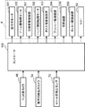
(1)システム全体構成
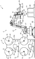
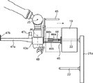
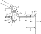
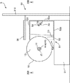
図1は、本実施形態に係るシート供給システム1の全体構成を概略的に示した平面図である。図2は、シート供給システム1の全体構成を概略的に示した側面図である。(1) Overall System Configuration FIG. 1 is a plan view schematically showing the overall configuration of a
シート供給システム1は、管状の芯部材11とその外周に巻きつけられたシート12とを有するロール10からシート12を供給するためのシステムである。
The
シート供給システム1は、シート供給装置(目標位置)2と、ロール載置部(載置位置)3と、ロール搬送装置200とを有する。ロール搬送装置200は、移送装置4と、中間処理装置5と、コントローラ100(制御器、図19参照)とを有する。
The
本実施形態では、シート供給システム1は、使い捨てのおむつを製造する製造システムで用いられる。この製造システムでは、シート供給システム1から供給されたシート12に各種加工を行って使い捨てのおむつが製造される。
In the present embodiment, the
(2)装置の詳細構造
各装置の詳細について説明する。以下では、移送装置4の後述するレール40に沿う方向であって図1の上下方向を前後方向といい、図1の上、下をそれぞれ前、後という。また、図1の左右方向を単に左右方向といい、図1の右、左をそれぞれ単に右、左という。(2) Detailed Structure of Device Details of each device will be described. In the following, the direction along the
(2−1)シート供給装置
シート供給装置2は、一対の支持壁21a,21aと、複数対の支持軸(ロール支持部)22と、複数のガイドロール23とを有する。(2-1) Sheet Supply Device The
各支持壁21aは、それぞれ床面90から上方に延びるとともに左右方向に延びており前後方向に沿って互いに平行に並んでいる。
The
各支持軸22は、ロール10を支持するための部材である。各支持軸22は、略円柱状を有しており、ロール10の芯部材11の内側に挿入されることでロール10を支持する。各支持軸22は、支持壁21a,21aから水平方向に延びている。図1および図2に示した例では、後側の支持壁21aには支持壁21aから後方に延びる4つ(2対)の支持軸22が設けられ、前側の支持壁21aには支持壁21aから前方に延びる4つ(2対)の支持軸22が設けられている。また、各支持壁21aには、その上部と下部とにおいて、それぞれ2つ(1対)の支持軸22が左右に並んで設けられている。
Each
各ガイドロール23は、それぞれシート12を所定の経路に沿って案内するためのものである。各ガイドロール23も、支持壁21a,21aから水平方向に延びている。
Each
支持軸22に支持されたロール10のシート12は、モータが支持軸22を回転駆動することでロール10から繰り出されていく。このシート12は、後工程の装置(不図示)によって引き取られることで、各ガイドロール23を介して前記経路に沿って搬送される。
The
ここで、支持軸22に支持されたロール10からシート12が繰り出されていくときのロール10の回転方向は支持軸22ごとに予め決まっている。各ガイドロール23は、この決まった回転方向にロール10が回転することではじめてシート12が適切に前記経路に沿って後工程に繰り出されるように、配置されている。
Here, the rotation direction of the
図2に示した例では、左側に設けられた支持軸22に支持されたロール10が実線で示した矢印のように支持軸22の先端側から見て時計回りに回転すると、このロール10からシート12が適切に繰り出されていく。一方、右側に設けられた支持軸22に支持されたロール10では、破線で示した矢印のように支持軸22の先端側から見て反時計回りにロール10が回転したときに、ロール10からシート12が適切に繰り出されていく。
In the example shown in FIG. 2, when the
ここで、使い捨てのおむつは、不織布やフィルム、ティッシュといった材質や幅が異なる複数種類のシートにより形成されている。これに対応して、シート供給装置2は、材質や幅や外径の異なる複数種類のロールから各シートを連続的に繰り出し可能となっている。すなわち、シート供給装置2の互いに異なる対の各支持軸22には、必要に応じてそれぞれ互いに種類の異なるロール10が支持され、これらロール10から互いに異なる複数種類のシートがそれぞれ後工程に向けて繰り出されていく。ただし、各ロール10の芯部材11の内径はほぼ同じとされており、シート供給装置2の全ての支持軸22の外径は、ほぼ同じに設定されている。
Here, the disposable diaper is formed of a plurality of types of sheets having different materials and widths such as a nonwoven fabric, a film, and a tissue. In response to this, the
(2−2)ロール載置部
ロール載置部3は、使用前のロール10が載置される部分である。本実施形態では、床面90の一部がロール載置部3として機能する。図1に示す例では、レール40を挟んでシート供給装置2と反対側(右側)において、中間処理装置5よりも前方および後方にそれぞれ1つずつロール載置部3が設けられている。図1に示した例では、前側のロール載置部3には外径が小さいロール10が載置され、後側のロール載置部3には外径が大きいロール10が載置されている。(2-2) Roll mounting section The roll mounting section 3 is a section on which the
図1および図2に示すように、ロール10は、芯部材11の軸が上下方向に延びる姿勢でロール載置部3に載置されている。本実施形態では、1または複数のロール10が、パレット30に載せられた状態でロール載置部3に搬入される。また、ロール10は、パレット30に載せられた状態でロール載置部3に載置される。
As shown in FIGS. 1 and 2, the
(2−3)移送装置
移送装置4は、前記のようにシート供給装置2とロール載置部3との間に位置して前後方向に延びるレール40と、レール40上を移動する作業用ロボット41とを備える。レール40は平行に並ぶ一対のレール部材40a,40aからなる。(2-3) Transfer Device The transfer device 4 is located between the
作業用ロボット41は、レール40上を摺動する走行部(本体部)42と、走行部42に連結されたアーム43とを備える。
The
走行部42には、走行用のモータ201(図19参照、以下、走行用モータという)が内蔵されている。走行部42ひいては作業用ロボット41は、走行用モータ201に駆動されてレール40上を移動する。
A traveling motor 201 (see FIG. 19, hereinafter referred to as traveling motor) is incorporated in the traveling
アーム43は、多関節アームである。アーム43は、走行部42に接続される基端部43aと、基端部43aに対して相対変位可能なヘッド(先端部)43eとを備える。
The
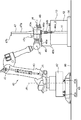
具体的には、図2に示すように、基端部43aは、上下方向に延びる旋回軸J0を中心として旋回可能な状態で走行部42に接続されている。アーム43は、水平方向に延びる第1軸J1を中心として搖動可能な状態で基端部43aに接続された第1アーム43bと、水平方向に延びる第2軸J2を中心として搖動可能な状態で第1アーム43bに接続された第2アーム43cと、水平方向に延びる第3軸J3を中心として搖動可能な状態で第2アーム43cに接続された第3アーム43dとを備える。そして、ヘッド43eは、この第3アーム43dに、第3軸J3と直交する方向に延びる第4軸J4を中心として旋回可能な状態で接続されている。
Specifically, as shown in FIG. 2, the
基端部43a、各アーム43b,43c,43dおよびヘッド43eは、作業用ロボット41に設けられた複数のモータによってそれぞれ駆動されて各軸J0〜J4回りに旋回または搖動する。以下では、基端部43a、各アーム43b,43c,43dおよびヘッド43eを駆動するモータをまとめてアーム駆動用モータ202(図19参照)という。
The
ヘッド43eには、移送側保持部44、押さえ部45、プッシャー(押し出し部)46、芯部材取り外し部47、ヘッド側カメラ48等が、ヘッド43eと一体に移動可能に取り付けられている。
A transfer
(i)移送側保持部
図3および図4は、ヘッド43eを第4軸J4と直交する方向の両側からそれぞれ見た概略側面図である。(I) Transfer Side Holding Section FIGS. 3 and 4 are schematic side views of the
移送側保持部44は、ロール10を保持するためのものである。
The transfer-
移送側保持部44は、アーム43のヘッド43eの一側面である取付側面(取付部)43fから第4軸J4と直交する方向に沿って延びるロール保持軸44aと、複数の圧接部44bとを有する(図5、図6参照)。移送側保持部44は、取付側面43fに、ロール保持軸44aおよび移送側保持部44の中心軸J5回りに回転可能に固定されている。移送側保持部44は、ハンド部回転用モータ302(図19参照)により、その中心軸J5まわりに回転駆動される。
The transfer-
ロール保持軸44aは、ロール10の芯部材11の内側に挿入されることが可能な形状を有している。ロール保持軸44aの外径は、芯部材11の内径よりもわずかに小さい寸法である。
The
具体的には、ロール保持軸44aは、取付側面43fに回転可能に固定される基端部と、ロール保持軸44aの長手方向の端部である先端部44a_2とを備える。この先端部44a_2は、自由端である。ロール保持軸44aは、その自由端である先端部44a_2が芯部材11の内側に差し込まれることで芯部材11の内側に挿入される。すなわちロール保持軸44aには、先端部44a_2側からロール10が取り付けられる。そして、ロール保持軸44aからは、この先端部44a_2側からロール10が引き抜かれる。
Specifically, the
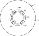
図5は、図2のV−V線断面図である。この図5に示すように、各圧接部44bは、図5の実線で示す位置であってロール保持軸44aの外周面からロール保持軸44aの径方向の外側に突出する圧接位置と、図5の破線で示す位置であって圧接位置よりもロール保持軸44aの径方向の内側に退避する待機位置との間で変位可能である。各圧接部44bは、圧接位置にある状態において、芯部材11の内周面に圧接する。待機位置にある状態では、ロール保持軸44aの径方向について、ロール保持軸44aの外周面の位置と各圧接部44bの外周面との位置とはほぼ同じになる。
FIG. 5 is a sectional view taken along line VV of FIG. As shown in FIG. 5, each
各圧接部44bは、ヘッド43eに取り付けられた圧接部駆動装置301(図19参照)により駆動される。圧接部駆動装置301は、機械的な駆動機構やエア等によって圧接部44bを駆動する。
Each
図5および図2に示すように、ロール保持軸44aの外周面には複数の孔が形成されている。各孔に圧接部44bがそれぞれ設けられている。各圧接部44bは、ロール保持軸44aの軸方向に沿って延びる板状部材である。各圧接部44bは、ロール保持軸44aの軸方向に沿う方向の複数の位置およびロール保持軸44aの周方向の複数の位置に、それぞれ圧接位置と待機位置との間で変位可能に配置されている。圧接部44bの外側表面には突起が設けている。圧接部44bが圧接位置に変位すると、これら突起の先端は、ロール3の芯部材11の内面に食いこむ。
As shown in FIGS. 5 and 2, a plurality of holes are formed on the outer peripheral surface of the
このように構成された移送側保持部44は、圧接部44bが待機位置にある状態でロール10の芯部材11の内側に挿入され、その後、圧接部44bが圧接位置まで移動して芯部材11の内周面に圧接することでロール10を保持する。
The transfer-
図6に示すように、ロール載置部3に載置されているロール10を保持する場合は、ロール保持軸44aがヘッド43eから下方に延びる状態で、移送側保持部44がロール10の上方に配置される。そして、この状態から移送側保持部44がロール10に向かって下降することで、ロール保持軸44aがロール10の芯部材11内に挿入される。その後、圧接部44bが芯部材11の内周面に圧接される。
As shown in FIG. 6, when holding the
(ii)押さえ部
押さえ部45は、移送側保持部44に保持されたロール10のシート12の最外周面上のシート12をロール10の外周面に拘束するためのものである。(Ii) Pressing Section The
具体的には、本実施形態では、ロール載置部3に搬入された各ロール10の最外周面上のシート12の端部には、テープT(図18参照)が貼り付けられている。シート12の端部は、このテープTによってロール10の外周面に拘束されている。そのため、シート供給装置2においてロール10からシート12を繰り出すためには、このテープTを取り外す必要がある。これに対して、本実施形態では、後述するように、ロール載置部3からシート供給装置2に搬送されるまでの間でテープTが除去されるようになっている。ここで、このようにテープTが除去されてシート12がロール10に拘束されなくなってしまうと、シート12の端部がめくれてロール10から離れた位置に移動してしまうおそれがある。そこで、本実施形態では、押さえ部45を設けて、押さえ部45によりこのシート12の端部がロール10から離間した位置へ移動するのを規制する。
Specifically, in the present embodiment, a tape T (see FIG. 18) is attached to the end portion of the
図2および図3に示すように、押さえ部45は、ヘッド43eの一側面に連結された支持板45aと、支持板45aの先端から移送側保持部44の軸と平行に延びる略円柱状の押さえ部本体45bとを備える。支持板45aは、図3に示すように、移送側保持部44の軸(ロール保持軸44aの中心軸)と平行に延びる軸回りに搖動可能にヘッド43eに連結されている。支持板45aは、押さえ部駆動装置303(図19参照)により搖動駆動される。支持板45aの搖動変位に伴い、押さえ部本体45bは移送側保持部44に接離する方向に移動する。
As shown in FIGS. 2 and 3, the holding
このように構成された押さえ部45は、通常状態では、図3の実線で示すように、押さえ部本体45bが移送側保持部44から最も離間する状態とされる。一方、前記のようにロール10の最外周面上のシート12が除去されると、支持板45aが搖動駆動される。これにより、押さえ部45は、図3の破線で示すように、押さえ部本体45bがロール10の外側面にロール10の径方向の外側から当接する状態とされる。この当接により、押さえ部45は、ロール10の最外周面上のシート12の端部またはその近傍をロール10に押さえつけてロール10の外周面上に拘束する。なお、押さえ部45が、最外周面上のシート12をその幅方向の全域に亘って押さえるのが好ましい。ただし、押さえ部45は、シート12の端部の移動を規制できるように構成されればよい。従って、押さえ部45が、シート12の幅方向の一部のみを押さえてもよい。
In the normal state, the holding
なお、押さえ部駆動装置303は、エア等によって押さえ部45の支持板45aを駆動する。
The holding
(iii)プッシャー
プッシャー46は、移送側保持部44に保持されているロール10を押し出して、このロール10を移送側保持部44から取り外すためのものである。(Iii) Pusher The
図3に示すように、プッシャー46は、移送側保持部44を囲む環状部材である。プッシャー46の外径は、ロール10の芯部材11の外径よりも大きく設定されている。プッシャー46は、スライド機構46b(図7参照)によってロール保持軸44aの軸方向に沿ってスライド可能にヘッド43eに連結されている。プッシャー46は、プッシャー駆動装置304(図19参照)によってスライド駆動される。
As shown in FIG. 3, the
プッシャー駆動装置304は、プッシャー46を、図7の破線で示すようにヘッド43eの側面(取付側面)43f近傍の位置と、図7の実線で示すようにロール保持軸44aの先端よりもさらに外側の位置との間で移動させる。プッシャー46は、このように移動することで、移送側保持部44に保持されていたロール10をその先端よりも外側に押し出して、ロール10を移送側保持部44から取り外す。
The
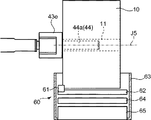
ここで、図7は、移送側保持部44に保持されているロール10をシート供給装置2の支持軸22に受け渡すときの様子を示した図である。この図7に示されるように、この受け渡し時には、まず、移送側保持部44は、その先端と支持軸22とが対向して移送側保持部44の中心軸J5と支持軸22の中心軸とがほぼ一致する位置に配置される。そして、移送側保持部44の先端からはみ出ている部分のロール10の芯部材11内に支持軸22の先端が挿入される。その後、プッシャー46によってロール10が移送側保持部44の先端側に押し出されることで、ロール10が支持軸22に受け渡される。なお、ロール10を移送側保持部44から取り外すときには、圧接部44bの位置は待機位置とされ、押さえ部本体45bはロール10の外周面から離間する位置に退避する。
Here, FIG. 7 is a diagram showing a state in which the
なお、プッシャー駆動装置304は、エア等によってプッシャー46を駆動する。
The
(iv)芯部材取り外し部
芯部材取り外し部47は、シート供給装置2の支持軸22から芯部材11を取り外すためのものである。すなわち、本実施形態では、作業用ロボット41が、シート供給装置2の支持軸22に支持されている使用済のロール10の芯部材11の取り外しも行うようになっている。なお、本実施形態では、芯部材11にシート12が残存している状態でロール10の使用が終了されるようになっている。これに伴い、芯部材取り外し部47は、シート12が巻かれた状態の芯部材11を取り外す。(Iv) Core Member Removing Section The core
図2および図4等に示すように、芯部材取り外し部47は、アーム43のヘッド43eの側面のうち取付側面43fと反対側の側面に設けられている。
As shown in FIGS. 2 and 4, the core
芯部材取り外し部47は、アーム43のヘッド43eの一側面から第4軸J4と直交する方向に延びる基板47aと、基板47aの先端に設けられて基板47aの長手方向と直交する方向に基板47aから延びる爪部47bと、基板47aの基端に設けられた一対の挟持部47cとを有している。
The core
図4に示す状態において、爪部47bの上縁には下側(基板47a側)に凹む切欠き47gが形成されている。
In the state shown in FIG. 4, a notch 47g that is recessed downward (on the side of the
挟持部47cは、芯部材11を把持するためのものである。図4に示すように、一対の挟持部47c,47cは、基板47aの幅方向に沿って並んでいる。これら挟持部47c,47cは、図4の実線と破線とに示すように、互いに接離する方向に駆動される。
The holding
このように構成された芯部材取り外し部47が使用済のロール10を支持軸22から取り外す時の動作を図8および図9を参照して説明する。
The operation of the core
まず、芯部材取り外し部47は、基板47aと支持軸22とが平行に延び、かつ、爪部47bが基板47aから上方に(支持軸22に向かって)延びる状態で、支持軸22の下方に配置される。次に、芯部材取り外し部47は、爪部47bの切欠き47gの内側に支持軸22の下部が入り込むように、上昇される。次に、芯部材取り外し部47は、図8の破線に示すように、支持壁21aから離間する方向に移動されて、芯部材11の端部(支持壁21a側の端部)に爪部47bが当接する位置に配置される。
First, in the core
そして、その後、芯部材取り外し部47は、図8の実線に示すように、支持軸22の軸方向に沿って支持壁21aから離間する方向に駆動される。これにより、爪部47bが芯部材11をこの支持壁21aから離間する方向に引き出す。このとき、芯部材取り外し部47は、芯部材11を完全に支持軸22から引き抜かず、芯部材11の一部の内側には、支持軸22が挿入されている。なお、図8では、図を明確にするために、芯部材11の内側に挿入されている支持軸22を実線で示している。
Then, after that, the core
その後、図9の実線に示すように、引き出された使用済みロール10の端部を、挟持部47cが挟持する。そして、この状態で、芯部材取り外し部47が、支持軸22から離間する方向に移動する。これにより使用済みロール10が支持軸22から完全に引き抜かれる。
After that, as shown by the solid line in FIG. 9, the holding
より詳しくは、図9に示すように、芯部材取り外し部47は、ヘッド43eから下方に延びるように、かつ、挟持部47c,47cの間に使用済みロール10が入り込むように、配置される。そして、挟持部47c,47cが互いに近接する方向に駆動されて、挟持部47c,47cが使用済みロール10の端部を挟み込む。この状態で、芯部材取り外し部47は、支持壁21aから離間する方向に移動され、これにより使用済みロール10が支持軸22から引き抜かれる。
More specifically, as shown in FIG. 9, the core
なお、挟持部47c,47cの駆動機構は、エア等によって挟持部47c,47cを駆動する。また、挟持部47cに保持された使用済のロール10は、廃棄場所(不図示)まで搬送されて廃棄される。
The drive mechanism of the holding
(v)ヘッド側カメラ
図2および図3等に示すように、ヘッド側カメラ48は、ヘッド43eに取り付けられている。ヘッド側カメラ48は、主として、ロール載置部3に載置されているロール10の芯部材11の位置を特定するために設けられている。具体的には、ヘッド側カメラ48により撮影された画像は、コントローラ100に送られる。コントローラ100は、ヘッド側カメラ48で撮影された画像に基づいて、ロール載置部3に載置されているロール10の芯部材11の中心位置を検出する。(V) Head-side camera As shown in FIGS. 2 and 3, the head-
このように、本実施形態では、ヘッド側カメラ48とコントローラ100とが、ロール載置部3に載置されているロール10の芯部材11の位置を検出する芯位置検出装置として機能する。なお、コントローラ100は、撮影された画像に基づいて、ロール10の外径の概略寸法も検出する。また、コントローラ100は、この検出したロール10の外径寸法に基づいて、ロール載置部3に載置されているロール10が規定寸法のロールであるか否かを判定する。また、後述するように、コントローラ100は、芯位置検出装置の一部として機能するとともに、走行用モータ201や各アーム駆動用モータ202を制御する制御器としても機能する。
As described above, in the present embodiment, the head-
本実施形態では、検出された芯部材11の中心位置は、ロール載置部3に載置されているロール10を移送側保持部44が保持する際に利用される。具体的には、ロール保持軸44aがロール10の芯部材11の内側に適切に挿入されるように、検出された芯部材11の中心位置に基づいて、ロール保持軸44aの姿勢と位置が調整される。例えば、ロール保持軸44aの先端部44a_2を下方に向け、中心軸J5上に芯部材11の中心位置がくるように、ロール保持軸44aの姿勢と位置が調整される。
In the present embodiment, the detected center position of the
ここで、本実施形態では、ロール10の搬送順序において、ロール載置部3における載置場所に優先順位が決められている。これに伴い、ヘッド側カメラ48は、まず、ロール載置部3に載置されているロール10の全体映像を撮影する。次に、撮影された画像に基づいて、優先順位が最も高い(より早期に搬送すべき)場所に載置されたロール10が特定される。そして、この特定されたロール10であって搬送対象となるロール10の近傍に、ヘッド43eが移動される。その後、搬送対象であるロール10の芯部材11の位置が検出される。そして、この位置に基づいて移送側保持部44の位置がさらに細かく調整される。
Here, in the present embodiment, in the transport order of the
例えば、ロール載置部3に上下方向に複数段にわたってロール10が載置される場合には、より上部に位置するロール10の方が優先順位が高く設定されている。
For example, when the
ロール10は、次の手順で移送側保持部44に保持される。
The
まず、ロール載置部3から所定高さ以上の位置であって、ロール載置部3に載置されているすべてのロール10がヘッド側カメラ48によって撮影される位置に、ヘッド43eが配置される。次に、コントローラ100が、ヘッド側カメラ48によって撮影された画像に基づき、ヘッド43eと、最も上方に位置するロール10との離間距離を算出する。例えば、撮影された画像におけるロール10の芯部材11の寸法から前記距離を算出する。
First, the
次に、前記距離に基づいて、ヘッド43eが、最も上方に位置するロール10に近接する位置まで下降される。この状態において、コントローラ100は、再び、ヘッド側カメラ48が撮影した画像に基づいて、ロール10の芯部材11の中心位置を検出する。次に、この芯部材11の中心位置の検出結果に基づいて、ロール保持軸44aの姿勢が、その先端部44a_2が下を向く姿勢とされる。また、移送側保持部44の中心軸J5上に、検出された芯部材11の中心位置がくるように、移送側保持部44の姿勢と位置が調整される。その後、ロール保持軸44aおよび移送側保持部44がロール10に向かって下降され、これによって、ロール保持軸44aがロール10の芯部材11内に挿入される。
Next, based on the distance, the
なお、水平方向についてもロール10の搬送順序について優先順位を定めてもよい。例えば、レール40からの距離に応じて優先順位を設定してもよい。例えば、レール40により近い位置に配置されたロール10から順に搬送されるようにしてもよい。
In addition, in the horizontal direction, the priority order may be set for the transport order of the
(2−4)中間処理装置
中間処理装置5は、中間処理を実施するための装置である。中間処理は、ロール10がロール載置部3に搬入されてからシート供給装置2の支持軸22にセットされるまでの間に行われる処理である。また、中間処理は、ロール10の状態がロール10からシート12を連続的に繰り出せる状態になるようにロール10に対して行うべき処理である。本実施形態では、この中間処理として、ロール10の巻方向を検出する処理と、移送側保持部44にロール10を持ち替えさせる処理(必要に応じて実施)と、ロール10の最外周面上のシート12を除去する処理とを実施する。また、中間処理として、ロール10の半径を検出する処理も実施する。
(2-4) Intermediate Processing Device The
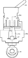
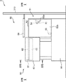
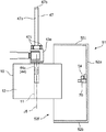
図10は、中間処理装置5の概略側面図である。中間処理装置5は、巻方向検出装置51と、載置台(持ち替え用載置部)58と、シート除去装置60と、ロール径検出センサ(ロール径検出装置)70とを備える。
FIG. 10 is a schematic side view of the
(i)ロール径検出センサ
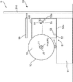
ロール径検出センサ70は、移送側保持部44に保持されているロール10の半径を検出するためのセンサである。本実施形態では、図1のXI−XI線断面図である図11に示すように、ロール径検出センサ70は、後述する遮光箱52の内側において、遮光箱52の後述する後壁52aに取り付けられている。(I) Roll Diameter Detection Sensor The roll
ロール径検出センサ70はいわゆる距離センサである。ロール径検出センサ70は、ロール10の中心軸とロール径検出センサ70との距離が予め設定された基準距離にある状態で、ロール径検出センサ70からロール10の外周面までの距離を測定する。この測定結果は、コントローラ100に送られる。コントローラ100は、この測定結果と前記基準距離とに基づいてロール10の半径を検出する。
The roll
本実施形態では、ロール10の半径の検出は、ロール10が移送側保持部44によって保持されたままで実施される。
In the present embodiment, the detection of the radius of the
具体的には、図11に示すように、移送側保持部44の中心軸J5が前後方向に延び、かつ、中心軸J5とロール径検出センサ70との左右の距離が基準距離となるように、移送側保持部44が配置される。この状態で、ロール径検出センサ70は、ロール10の外周面までの距離を測定する。その後、コントローラ100は、前記基準距離からこの測定した距離を差し引いた値を、ロール10の半径として検出する。
Specifically, as shown in FIG. 11, the central axis J5 of the transfer-
本実施形態では、ロール10の周方向の複数の位置に対してロール10の半径の検出が行われる。コントローラ100はこれらの平均値をロール10の半径とする。
In the present embodiment, the radius of the
具体的には、移送側保持部44が中心軸J5回りに回転駆動される。そして、ロール径検出センサ70は、移送側保持部44の回転角度が異なる複数のタイミングでロール10の外周面までの距離を測定する。これによりロール10の周方向の複数の位置における半径が検出される。そして、これら複数の位置の半径の平均値が算出される。
Specifically, the transfer-
(ii)巻方向検出装置
巻方向検出装置51と載置台58とは、移送側保持部44に、ロール10を適切な方向で保持させるための装置である。(Ii) Winding Direction Detection Device The winding
具体的には、前記のように、本実施形態では、ロール保持軸44aには、その先端部44a_2側からしかロール10を進入させることができない。また、ロール保持軸44aからロール10を引き抜く場合には、ロール保持軸44aの先端部44a_2側からしかロール10を引き抜くことができない。そのため、図7に示すように移送側保持部44から支持軸22にロール10が受け渡されて、ロール10が支持軸22に保持された状態におけるロール10の巻方向は制約される。具体的には、この状態におけるロール10の巻方向は、ロール10の芯部材11にロール保持軸44aを挿入させたとき、すなわち、移送側保持部44がロール10を保持したとき、のロール10の巻方向に制約されてしまう。
Specifically, as described above, in the present embodiment, the
一方で、前記のように、シート供給装置2では、ロール10からシート12を繰り出すときのロール10の回転方向が、支持軸22毎に決まっている。そのため、支持軸22には、その回転方向に合わせてロール10をセットする必要がある。
On the other hand, as described above, in the
例えば、図2に示す例では、前記のように、左側に位置する支持軸22に支持されたロール10は、支持軸22の先端側から見て時計回りに回転することでシート12を繰り出していく。また、右側に位置する支持軸22に支持されたロール10は、支持軸22の先端側から見て反時計回りに回転することでシート12を繰り出していく。従って、支持軸22には、その回転方向に合った巻き方向のロール10をセットする必要がある。
For example, in the example shown in FIG. 2, as described above, the
従って、移送側保持部44に保持されているロール10の巻方向が、シート12の繰り出し方向と対応する方向でない場合には、移送側保持部44から支持軸22にロール10を受け渡す前に、移送側保持部44にロール10を持ち替えさせる必要がある。例えば、ロール10の巻方向が支持軸22の先端側から見て時計回りになるように支持軸22にロール10をセットせねばならない場合には、移送側保持部44は、ロール10を、その巻方向がロール保持軸44aの先端側から見て反時計回りとなる状態で保持する必要がある。
Therefore, when the winding direction of the
そこで、本実施形態では、巻方向検出装置51によってロール10の巻方向を検出する。そして、この検出結果に応じて、ロール10の持ち替えを行うかどうかが決定される。具体的には、検出されたロール10の巻方向がシート12の繰り出し方向と対応しない場合は、載置台58を用いて、後述するように、ロール保持軸44aの芯部材11への挿入方向が変更されて移送側保持部44はロール10を持ち替える。
Therefore, in the present embodiment, the winding
図12は図11に対応する図である。図13は、図12のXIII−XIII線断面図である。 FIG. 12 is a view corresponding to FIG. 11. FIG. 13 is a sectional view taken along line XIII-XIII in FIG.
巻方向検出装置51は、遮光箱52と、遮光箱52の内側に設けられたライト53および巻方向検出用カメラ54とを有する。なお、遮光箱52は、巻方向検出用カメラ54での撮影時に外乱光を遮蔽するものである。巻方向検出用カメラ54が巻き方向を検出するために十分な光量を得られる場合は、遮光箱を省略してもよい。
The winding
遮光箱52は、左側(レール40側)に開口する箱状部材である。具体的には、遮光箱52は、上下方向および前後方向に延びる後壁52aと、後壁52aの前後方向の両縁から左側にそれぞれ延びる横壁52b,52cと、横壁52b,52cの各上縁間にわたって水平に延びる上壁52dと、横壁52b,52cの各下縁間にわたって水平に延びる下壁52eとを有している。そして、遮光箱52には、横壁52b,52c、上壁52dおよび下壁52eの左側の縁とによって囲まれた開口部52fが形成されている。
The
図10〜図13に示すように、開口部52fは、開口部52fから遮光箱52の内側にロール10の外周面の一部を挿入することができる大きさを有している。開口部52fからロール10の外周面の一部が遮光箱52内に挿入された状態で、ロール10の巻方向の検出が実施される。また、移送側保持部44にロール10が保持された状態で、ロール10の巻方向の検出が実施される。
As shown in FIGS. 10 to 13, the
具体的には、ロール保持軸44aが前後方向に延びる姿勢とされた状態で、移送側保持部44に保持されているロール10の外周面の周方向の一部が、シート12の幅方向全体にわたって遮光箱52の内側に挿入される。開口部52fの前後方向の寸法は、使用されるロール10のうち軸方向の寸法(シート12の幅方向の寸法)が最大となるロール10の軸方向の寸法よりも十分に大きい値に設定されている。
Specifically, in a state where the
ライト53は、遮光箱52の下壁52eの開口部52f寄りの位置に取り付けられている。ライト53は、上方に向かって光を照射し、遮光箱52内に挿入されたロール10の外周面を照らす。
The light 53 is attached to the
巻方向検出用カメラ54は、遮光箱52の後壁52aの上下方向の略中央に取り付けられている。巻方向検出用カメラ54は、開口部52fから遮光箱52の内側に挿入されたロール10の外周面を撮影する。
The winding
巻方向検出用カメラ54により撮影された画像は、コントローラ100に送られる。コントローラ100は、巻方向検出用カメラ54により撮影された画像からロール10の巻方向を検出する。このように、本実施形態では、巻方向検出用カメラ54とコントローラ100とが、ロール10の巻方向を検出する巻方向検出装置として機能する。
The image captured by the winding
具体的には、コントローラ100は、ロール10の最外周面上に位置するシート12の端部に形成された影を検出する。コントローラ100は、この影の向きによってロール10の巻方向を検出する。すなわち、遮光箱52内にロール10の外周面が挿入された状態であって外部からの光が抑えられた状態でロール10の外周面にライト53から光が照射されたときに、シート12の端部が下方から上方に向かっている場合は、ロール10の外周面に位置するシート12の端部の周囲に、この端部からロール10の巻方向に沿って延びる影が形成される。一方、シート12の端部が上方から下方に向かっている場合は、この端部から強い反射光が反射される。従って、コントローラ100は、巻方向検出用カメラ54により撮影された画像からこの影の向きあるいは反射光を検出して、ロール10の巻方向を判定する。
Specifically, the
ここで、シート12の端部がロール10の外周面のどの位置に配置されているのかは不明である。
Here, it is unclear at which position on the outer peripheral surface of the
そこで、本実施形態では、ロール10の外周面の周方向の全領域にわたって前記影および影の向きを検出する。具体的には、移送側保持部44がその中心軸J5回りに回転駆動されて、巻方向検出用カメラ54により撮影される領域が順次変更される。移送側保持部44は一回転され、コントローラ100は、ロール10の外周面の周方向の全体について撮影された画像からシート12の端部の影の向きや反射光を検出して、ロール10の巻方向を判定する。このとき、ロール10外周面におけるシート12端部の位置もあわせて検出される。
Therefore, in this embodiment, the shadow and the direction of the shadow are detected over the entire area of the outer peripheral surface of the
(iii)載置台
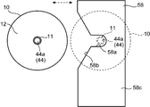
図14は、載置台58を示す概略平面図である。載置台58は、ロール10が載置される板状部材であり、その上面はロール10を上方から載置可能な水平に延びる載置面58cとされている。図1に示すように、載置台58は、遮光箱52の上方において、遮光箱52の一部と平面視で重複する位置に配置されている。本実施形態では、載置台58の全体が遮光箱52の上壁52dと重複している。(Iii) Mounting Table FIG. 14 is a schematic plan view showing the mounting table 58. The mounting table 58 is a plate-shaped member on which the
載置台58には、溝部58aが形成されている。溝58aは、載置台58を上下方向(第1の方向)に貫通して水平方向(第2の方向)に開口している。図例では、溝部58aは、レール40側(左側)に開口している。具体的には、載置台58のレール40側の側面の前後方向の略中央部分には、右側に凹む切欠き58bが形成されている。この切欠き58bの前後方向の中央部分と溝部58aとが連通している。
A
溝部58aの内径(前後方向の寸法)は、移送側保持部44の外径よりも大きく設定されている。これに伴い、移送側保持部44は、載置台58の左側と下側とからこの溝部58a内に進入できる。載置台58は、昇降装置310によって昇降可能に床面90に支持されている。
The inner diameter (dimension in the front-rear direction) of the
この載置台58を用いたロール10の持ち替え手順を、図14〜図16を用いて説明する。
A procedure for changing the
まず、載置台58の上方からロール10を下降させていきロール10を載置面58c上に載置する。具体的には、図15に示すように、ヘッド43eが載置台58の上方に配置されて、移送側保持部44がヘッド43eから下方に延びる姿勢で載置台58に向かって下降する。ロール10が載置面58c上に載置されると、圧接部44bが待機位置に戻され、移送側保持部44が上方に移動される。ロール10は重力の作用で載置面58c上に残され、これにより、ロール10から移送側保持部44は引き抜かれる。
First, the
次に、図16に示すように、ロール10が載置された載置台58を上方に移動させる。次に、ヘッド43eが載置台58の下方に配置され、かつ、移送側保持部44がヘッド43eから上方に延びる姿勢とされる。次に、ヘッド43eが上昇して、移送側保持部44が載置台58の下方から溝部58aおよびロール10の芯部材11内の所定位置に挿入される。次に、圧接部44bが圧接位置に移動されて芯部材11の内周面に圧接し、移送側保持部44がロール10を保持する。次に、ヘッド43eが僅かに上昇してロール10を持ち上げたのち、図16の破線および図14の実線で示すように、移送側保持部44が溝部58aおよび切欠き58bを通って載置台58の外側まで左側に移動する。
Next, as shown in FIG. 16, the mounting table 58 on which the
(iv)シート除去装置
図17は、図10のXVII−XVII線断面図である。図18は、図10のXVIII−XVIII線断面図である。(Iv) Sheet Removing Device FIG. 17 is a sectional view taken along line XVII-XVII in FIG. 18 is a sectional view taken along line XVIII-XVIII in FIG.
シート除去装置60は、ロール10の最外周面上のシート12を除去するための装置である。ロール10の最外周に位置するシート12は、外部に露出しているために汚れている場合がある。そこで、シート除去装置60は、最外周のシート12を除去する。また、本実施形態では、ロール10の最外周面上に位置するシート12の端部は、テープTによってロール10に固定されている。シート除去装置60は、最外周のシート12を除去することでこのテープTも除去する。
The
シート除去装置60は、シート12を切断する第1カッター(第1切断部)61と、第1カッター61をスライド可能に支持するカッター支持部62と、シート12を切断する第2カッター64(第2切断部)と、引出装置65と、複数のガイドロール69と、これらを支持する支持壁部63とを有する。
The
シート除去装置60は、第1カッター61が左右方向にスライド可能な状態で配置されている。第1カッター61は、シート12に接触した状態でスライド移動することでシート12を切断する。一方、第2カッター64は、シート12を上下に挟み込む切断刃(図示省略)をそれぞれ有しており、シート12をこれら切断刃の間で挟圧することでシート12を切断する。第1カッター61および第2カッター64は、カッター駆動装置320(図19参照)によって駆動される。
The
引出装置65は、シート12の端部であって第1カッター61によりシート12が切断されることで形成されたシート12の端部を引き出すとともに、引出経路Lであってロール10からロール10の径方向に離れる方向に延びる引出経路Lに沿うようにシート12を配置するための装置である。引出装置65は、不図示の吸引装置に接続されており、シート12を吸引することで、シート12の端部を引出し、シート12を引出経路Lに沿って延びるように配置する。
The pull-out
各ガイドロール69は、シート12を引出装置65に案内するためのものである。シート12は、上側に位置するガイドロール69と下側に位置するガイドロール69との間に導入されて、引出装置65に導かれる。
Each
本実施形態では、ロール10が移送側保持部44によって支持されたままで、第1カッター61によるシート12の切断が実施される。これに伴い、ロール10は、移送側保持部44に保持された状態でシート除去装置60に搬入される。
In the present embodiment, the
このとき、図17に示すように、ロール10は、作業用ロボット41によって、左右方向であって第1カッター61がスライド移動する方向に沿って芯部材11が延びる姿勢で、シート除去装置60に搬入される。また、このとき、第1カッター61がロール10の最外周のシート12と当接可能となるように、移送側保持部44の位置が調整される。具体的には、シート除去装置60に設けた図示しないタッチセンサなどに基づいて、移送側保持部44の位置が、この第1カッター61とシート12とが当接可能となる位置に調整される。
At this time, as shown in FIG. 17, the
このように配置された後、ロール10のシート12はシート除去装置60によって次の手順で切除される。
After being arranged in this way, the
まず、第1カッター61がスライド駆動される。これによりロール10の最外周面上のシート12は、所定位置(第1位置)でその幅方向に沿って切断される。なお、この所定位置のロールの周方向についての位置は、移送側保持部44が回転されることで調整される。具体的には、前記巻方向検出装置51で検出されたシート12の端部の位置に基づいて、シート12の端部が第1カッター61に対して所定位置となるように、移送側保持部44が回転される。
First, the
次に、第1カッター61によって切断されることで形成されたシート12の端部(以下、適宜、切断端部という)が引出装置65と対応する位置になるように、移送側保持部44が回転駆動される。これに伴い、引出装置65内にシート12の切断端部が引き込まれて、シート12は引出経路Lに沿ってロール10から延びる状態になる。
Next, the transfer-
その後、さらに、切断端部から所定の長さ分のシート12が引出装置65内に引き込まれるように、移送側保持部44が、シート12を繰り出す方向(図18の例では、この図18において時計回り)に回転駆動される。具体的には、シート12のうちテープTが張り付けられた端部であってシート12のもともとの端部からロール10の周長以上離れた部分と、第2カッター64とが対向するまで、シート12が引出装置65内に引き込まれるように、移送側保持部44が回転駆動される。本実施形態では、切断端部すなわち第1位置からロール10の周長以上離間した部分が、第2カッター64と対向するようにシート12が繰り出される。
Thereafter, the transfer
次に、第2カッター64により、シート12のうち第2カッター64と対向する部分が切断される。このとき、第2カッター64は、前記のようにシート12のうち第1位置からロール10の周長以上離間した位置(第2位置)と対向しており、この第2位置でシート12を切断する。
Next, the
この切断により、シート12のうち第1位置からロール10の周長以上離間した第2位置までの間の部分、すなわち、シート12のうちもともとの端部から第1位置までの部分と、第1位置から第2位置までの部分とを合わせた部分が切除される。これに伴い、もともとのシート12の端部がロール10から除去される。また、ロール10の最外周面に位置して汚損等しているシート12が除去される。
As a result of this cutting, the portion of the
切除されたシート12は、引出装置65によって所定の廃棄場所に吸い出される。
The
その後は、移送側保持部44が、シート12を巻き取る方向に回転駆動される。これにより、第2位置での切断により形成されたシート12の新たな端部が、ロール10の外周面上に戻される。
After that, the transfer
ここで、本実施形態では、前記のようにロール径検出センサ70によってロール10の半径が検出されている。そこで、前記のように、第2位置でシート12を切断した後、シート12の端部をロール10に戻す場合において、この検出された半径を用いて移送側保持部44およびロール10の回転角度を制御する。具体的には、第2カッター64からロール10の最外周面までの距離(例えば、引出装置65と移送側保持部44の中心軸との距離からロール10の半径を差し引くことで算出される)と、ロール10の半径とを用いて、移送側保持部44の回転角度を算出する。また、第2カッター64によって形成されたシート12の新たな端部をロール10の最外周面まで移動させるために必要な移送側保持部44の回転角度を算出する。そして、この角度分以上、移送側保持部44を回転させる。これにより、シート12の新たな端部がより確実にロール10の最外周面上に戻される。
Here, in the present embodiment, the radius of the
(v)コントローラ
図19は、コントローラ100の入出力を示したブロック図である。コントローラ100には、ヘッド側カメラ48、巻方向検出用カメラ54、ロール径検出センサ70等からの信号が入力される。コントローラ100は、これらの入力信号に基づいて、移送装置4、ライト53、昇降装置310、およびカッター駆動装置320を制御する。詳細には、コントローラ100は、作業用ロボット4に設けられた走行用モータ201、アーム駆動用モータ202、圧接部駆動装置301、ハンド部回転用モータ302、押さえ部駆動装置303、プッシャー駆動装置304を制御して、これにより作業用ロボット41を制御する。(V) Controller FIG. 19 is a block diagram showing the input / output of the
コントローラ100によって実施される全体の処理について、図20のフローチャートを用いて説明する。
The overall processing performed by the
まず、ステップS1において、コントローラ100は、走行用モータ201およびアーム駆動用モータ202を制御して、作業用ロボット41に使用済のロール10を支持軸22から取り外させる。
First, in step S1, the
具体的には、コントローラ100は、シート供給装置2に作業用ロボット41を移動させる。次に、コントローラ100は、前記のように、芯部材取り外し部47を、支持軸22の下方に配置した後上昇させ、さらにその後、支持壁22から離間する方向に移動させる。これにより、コントローラ100は、使用済のロール10の芯部材11の端部に、爪部47bを当接させる。次に、コントローラ100は、芯部材取り外し部47を支持壁21aから離間させて、芯部材取り外し部47に使用済のロール10の一部を支持軸22から引き出させる。その後、コントローラ100は、挟持部47cによって使用済のロール10を把持させて、芯部材取り外し部47にロール10を支持軸22から引き抜かせる。そして、コントローラ100は、芯部材取り外し部47に廃棄場所にて使用済のロール10を廃棄させる。
Specifically, the
次に、ステップS2において、コントローラ100は、作業用ロボット41をロール載置部3に移動させる(移動工程)。
Next, in step S2, the
具体的には、コントローラ100は、走行用モータ201を制御して、作業用ロボット41をロール載置部3と対向する位置に移動させる。
Specifically, the
次に、ステップS3において、コントローラ100は、ロール10の芯部材11の位置を検出する。具体的には、コントローラ100は、前記のように、ヘッド側カメラ48にロール載置部3に載置されているロール10を撮影させる。また、コントローラ100は、撮影された画像に基づいて、ロール10の芯部材11の中心位置を検出する。前記のように、本実施形態では、まず、ロール載置部3に載置されているロール10の全体映像が撮影された後、優先順位が高いロール10であって次に搬送するべきロール10が特定され、その後、このロール10の芯部材11の中心位置が検出される。あわせて、コントローラ100はロール10の外径の概略寸法を検出し、対象のロール10が規定寸法であることを確認する。
Next, in step S3, the
次に、ステップS4において、コントローラ100は、アーム駆動用モータ202、圧接部駆動装置301を制御して、作業用ロボット41の移送側保持部44にロール10を保持させる(ロール取得工程)。
Next, in step S4, the
具体的には、コントローラ100は、前記のように、移送側保持部44を上方からロール10の芯部材11内に進入させるとともに、圧接部44bを圧接位置に移動させて芯部材11の内周面に圧接させ、これにより移送側保持部44にロール10を保持させる。このとき、コントローラ100は、前記のように、ヘッド側カメラ48で撮影された画像に基づいて移送側保持部44の位置を調整しながら移送側保持部44を芯部材11内に進入させる。このようにして移送側保持部44にロール10が保持されると、コントローラ100はアーム駆動用モータ202を制御して、移送側保持部44の姿勢を、その中心軸J5が水平となるように速やかに変更する。このようにすれば、圧接部駆動装置301に何らかのトラブルが生じて、圧接部44bの圧接力が消失された場合でも、ロール10が移送側保持部44から容易に抜け落ちるのが防止される。
Specifically, as described above, the
次に、ステップS5において、コントローラ100は、走行用モータ201を制御して、作業用ロボット41を中間処理装置5に移動させる。
Next, in step S5, the
次に、ステップS6において、コントローラ100は、アーム駆動用モータ202およびハンド部回転用モータ302を制御して、ロール10の半径を検出する(中間処理工程)。
Next, in step S6, the
具体的には、コントローラ100は、アーム駆動用モータ202を制御して、前記のように、移送側保持部44が前後方向に延びて移送側保持部44の中心軸J5とロール径検出センサ70との距離が基準距離となるように、移送側保持部44を配置する。そして、コントローラ100は、ロール径検出センサ70によって検出されたロール径検出センサ70とロール10の外周面との距離に基づいて、ロール10の半径を検出する。また、このとき、コントローラ100は、ハンド部回転用モータ302を制御して、移送側保持部44を回転させてロール10の周方向の複数の位置についてその半径を検出するとともに、それを平均してロール10の半径を算出する。
Specifically, the
次に、ステップS7において、コントローラ100は、ロール10の巻方向を検出する(巻方向検出工程、中間処理工程)。
Next, in step S7, the
具体的には、コントローラ100は、アーム駆動用モータ202を制御して、移送側保持部44をその中心軸J5が前後方向に延びる姿勢とする。また、ロール10を開口部52fから遮光箱52内に挿入し、ロール10の外周面の一部を遮光箱52内に配置する。次に、コントローラ100は、ライト53およびハンド部回転用モータ302を制御して、移送側保持部44をその中心軸J5回りに回転させつつ、ロール10の外周面をライト53によって照明し、かつ、巻方向検出用カメラ54にロール10の外周面を撮影させる。そして、コントローラ100は、撮影された画像に基づいてロール10の巻方向を検出する。あわせて、コントローラ100は、撮影された画像に基づいてロール10の最外周面上におけるシート12の端部の位置も検出する。
Specifically, the
次に、ステップS8において、コントローラ100は、検出した巻方向が、移送側保持部44が保持しているロール10が搬送される予定である支持軸22の繰り出し方向と対応する方向であるか否かを判定する。
Next, in step S8, the
ステップS8の判定がNOであって、検出した巻方向が繰り出し方向ではない場合は、ステップS20に進む。ステップS20〜S21では、コントローラ100は、アーム駆動用モータ202、圧接部駆動装置301を制御して、作業用ロボット41にロール10を持ち替えさせるロール持ち替え工程(中間処理工程)を実施する。
When the determination in step S8 is NO and the detected winding direction is not the feeding direction, the process proceeds to step S20. In steps S20 to S21, the
具体的には、ステップS20にて、コントローラ100は、ロール10を載置台58の載置面58c上に載置するロール載置工程を実施する。
Specifically, in step S20, the
次に、ステップS21にて、ロール10から移送側保持部44を引き抜く引き抜き工程を実施する。
Next, in step S21, a pulling-out step of pulling out the transfer
次に、ステップS22にて、コントローラ100は、載置台58を上昇させて、載置台58の溝部58a内に下方から移送側保持部44を再度挿入してロール10を保持させる再ロール保持工程を実施する。そして、コントローラ100は、移送側保持部44を切欠き58bを通って載置台58の外側に移動させる。なお、コントローラ100は、この持ち替え処理が終了すると載置台58を下降させる。
Next, in step S22, the
ステップS20の後は、ステップS10に進む。 After step S20, the process proceeds to step S10.
一方、ステップS8の判定がYESであって、検出した巻方向が支持軸22の繰り出し方向に対応する方向である場合は、ステップS10に進む。すなわち、本実施形態では、移送側保持部44に保持されたロール10の巻方向が繰り出し方向に対応した方向である場合には、ステップS20〜S22を実施せず(ロール10を載置台58に載置させることなく)ステップS10に進む。
On the other hand, if the determination in step S8 is YES and the detected winding direction is the direction corresponding to the feeding direction of the
ステップS10では、コントローラ100は、走行用モータ201等を制御して、ロール10をシート除去装置60に移動させる。
In step S10, the
また、ステップS10において、コントローラ100は、アーム駆動用モータ202およびカッター駆動装置320を制御して、ロール10の最外周面上のシート12を除去する(シート除去工程、中間処理工程)。
In step S10, the
具体的には、コントローラ100は、前記のように、ロール10を、第1カッター61とロール10の外周面上のシート12とが当接可能となる位置に配置する。コントローラ100は、第1カッター61に、ロール10の最外周面上のシート12を、所定位置(第1位置)で切断させる。その後、コントローラ100は、移送側保持部44およびロール10を回転させることで、最初に切断された第1位置から繰出方向上流側のシート12を、引出経路Lに沿ってロール10から繰り出すとともに引出装置65内に引き込ませる。次に、コントローラ100は、第2カッター64に、第1位置からロール10の1周分以上離れた位置(第2位置)で、シート12を切断させる。そののち、コントローラ100は、繰り出されていたシート12を巻き戻して、第2位置に形成された新しい端部をロール10の最外周面上の所定位置に配置する。
Specifically, as described above, the
次に、ステップS11にて、コントローラ100は、押さえ部駆動装置303を制御して、押さえ部45に、ロール10の外周面上のシート12の端部(ステップ10で形成された新しい端部)またはその近傍を、ロール10に拘束させる。具体的には、ステップS10にてシート12が切断された後、ロール10が支持壁部63の外側に移動すると、コントローラ100は、すぐさま押さえ部45を駆動する。そして、前記のように、コントローラ100は、ロール10の外側面に押さえ部本体45bをロール10の径方向の外側からロール10に当接させて、ロール10の外周面上のシート12の端部またはその近傍を、ロール10に押さえつけてロール10の外周面上に拘束する。
Next, in step S11, the
次に、ステップS12にて、コントローラ100は、走行用モータ201等を制御して、ロール10をシート供給装置2に移動させる。
Next, in step S12, the
その後、ステップS13にて、コントローラ100は、アーム駆動用モータ202、圧接部駆動装置301、押さえ部駆動装置303およびプッシャー駆動装置304を制御して、移送側保持部44に保持されているロール10を支持軸22にセットする(セット工程)。
After that, in step S <b> 13, the
具体的には、コントローラ100は、前記のように、移送側保持部44を支持軸22と対向するように配置する。コントローラ100は、ロール10の芯部材11のうち移送側保持部44の先端からはみ出ている部分の内側に、支持軸22の先端を挿入する。そして、コントローラ100は、圧接部44bを待機位置とし、かつ、押さえ部本体45bをロール10の外周面から離間させた後、プッシャー46によってロール10を移送側保持部44から支持軸22側に押し出す。これにより、ロール10の芯部材11内に支持軸22が挿入されて、ロール10が支持軸22の所定位置にセットされる。
Specifically, the
(3)作用等
以上のように、本実施形態に係るロール搬送装置200を含むシート供給システム1では、ロール10が載置されるロール載置部3と、載置台58を含みロール10に各種処理を施すための中間処理装置5と、シート12を連続的に繰り出すシート供給装置2との全てが、移送側保持部44の移動範囲に配置されている。そして、ロール載置部3において移送側保持部44がロール10を保持した後、中間処理装置5を経由してシート供給装置2にロール10が移動するように、コントローラ100によって作業用ロボット41が制御される。(3) Actions, etc. As described above, in the
そのため、ロール載置部3に載置されているロール10を、シート供給装置2に自動的に供給することができる。また、中間処理装置5によってロール10に各中間処理を施すことができる。従って、ロール載置部3に載置されているロール10をシート供給装置2に搬送して支持軸22にセットする作業および前記中間処理を、作業者が行う必要がない。このことは、作業効率を高くする。また、中間処理が施されて適切な状態となったロール10を、シート供給装置2にセットすることができる。
Therefore, the
さらに、装置全体の構成を簡素化することができる。すなわち、このシート供給システム1では、ロール10の搬送先がどの支持軸22であるかに関わらず、ロール載置部3に載置されている全てのロール10が、中間処理装置5を経由して支持軸22に搬送される。そのため、支持軸22毎等にロール10に中間処理を施すための装置を個別に設ける必要がない。従って、中間処理装置5を複数のロール10に対して共通して利用することができる。このことは、装置の簡素化を実現する。
Furthermore, the configuration of the entire device can be simplified. That is, in this
特に、このシステム1では、ロール10の搬送途中にロール持ち替え工程が実施されて、ロール10の搬送途中で移送側保持部44がロール10を持ち替えることが可能となっている。そのため、ロール10を、その巻方向が適切な方向となった状態で、シート供給装置2に供給することができる。そして、これにより、ロール載置部3においてロール10の巻方向が適切な方向となるように、ロール10の姿勢を変更する必要がない。また、ロール10が支持軸22に受け渡されるたびに、このロール10の姿勢をシート供給装置2に適合した姿勢に作業者が変更する必要がない。従って、このロール10の姿勢の調整作業あるいは変更作業を省略することができ、作業効率をより一層たかめることができる。
In particular, in the
また、この実施形態では、載置台58に前記のように構成された溝部58aを形成する、という簡単な構成でロール10の持ち替えを実現することができる。
Further, in this embodiment, the
また、この実施形態では、載置台58の載置面58cにロール10が、その軸が上下方向に延びる姿勢で載置されるようになっている。従って、ロール10の軸が水平方向等に延び、且つ、ロールの外周面が載置台58と当接する姿勢で、ロール10が載置台58に載置される場合に比べて、ロール10の外周面が変形するのを抑制することができる。特に、この実施形態では、ロール10のシートとして比較的やわらかい不織布やティッシュ等が用いられているので、ロール10は変形しやすい。従って、前記実施形態のように構成すれば、効果的にロール10の変形を抑制することができる。
Further, in this embodiment, the
また、このシート供給システム1では、巻方向検出装置51を設け、移送側保持部44に保持されているロール10の巻方向を検出し、この巻方向が前記繰り出し方向に対応する方向でない場合にのみ、ロール10が載置台58に載置されるようになっている。
Further, in the
そのため、ロール10の巻方向をより確実に適切な方向とした状態で、ロール10をシート供給装置2に供給することができる。
Therefore, the
さらに、移送側保持部44によってロール10が保持されている状態で、ロールの巻方向が検出される。従って、ロール10の巻方向を検出する際にロール10を保持するための装置、を別途設ける必要がなく、装置を簡素化することができる。また、この保持のための装置と移送側保持部44との間でのロールの受け渡しを省略して、効率よくロールを搬送することができる。
Furthermore, the winding direction of the roll is detected while the
また、ロール搬送装置200では、載置台58が巻方向検出装置51の上方に配置されている。そのため、装置全体の水平方向の寸法を小さく抑えることができる。また、移送側保持部44の水平方向の移動距離も小さく抑えることができる。
Further, in the roll transport device 200 , the mounting table 58 is arranged above the winding
また、このシート供給システム1では、作業用ロボット41がレール40上を移動可能となっている。そのため、作業用ロボット41を大型化することなく、移送側保持部44の移動範囲を広くして、より広範囲にわたってロール10を搬送することができる。
Further, in the
また、このシート供給システム1では、移送側保持部44を芯部材11内に挿入させることで、移送側保持部44にロール10を保持させている。そのため、ロール10の外周面を把持することでロール10を保持する場合等に比べて、ロール10の変形を抑制した状態でロール10を保持することができる。特に、前記のように使い捨ておむつではシートとして不織布やティッシュといった比較的やわらかい材質のシートが用いられる。そのため、このシートにより形成されたロールの外周面を把持した場合にはロール10が変形してしまう。これに対して、本実施形態では、移送側保持部44を芯部材11内に挿入させることで移送側保持部44にロール10を保持させているため、ロール10の変形しつつロール10を搬送することができる。
Further, in the
(4)変形例
前記実施形態では、巻き方向検出装置51を備える場合について説明した。しかし、ロール載置部3において移送側保持部44が取得したロール10の巻き方向(移送側保持部44に保持されている状態でのロール10の巻方向)がシート供給装置2でのロール10の巻方向に対応する方向と一致しているかが明らかであれば、巻き方向検出装置51は省略可能である。例えば、ロール載置部3でのロール10が全て同じ巻き方向に揃えられている場合は、移送側保持部44に保持された状態においてロール10の巻き方向は一定である。そのため、一対の支持部22にセットされるロール10の巻き方向が互いに異なる場合であっても、搬送先の支持部22が特定されることにより、ロール10の巻方向が、搬送先の支持部22におけるロール10の巻方向に対応しているか否かを容易に判断することができる。したがって、この場合は巻き方向検出装置51を備えていなくてもよい。
(4) Modified Example In the above embodiment, the case where the winding
前記実施形態では、作業用ロボット41がレール40上を移動する場合について説明したが、レール40は省略してもよい。
In the above embodiment, the case where the
また、前記実施形態では、ロール10の最外周面に位置するシート12の端部に光が照射されて、その周囲に生じる影の向きや反射光によって、ロール10の巻方向が検出される場合について説明した。しかし、ロール10の巻方向を検出する具体的な手順はこれに限らない。
Moreover, in the said embodiment, when the edge part of the sheet |
また、前記実施形態では、ロール10がその軸が上下方向に延びる姿勢で載置台58に載置される場合について説明した。しかし、ロール10が載置台58に載置されるときの姿勢はこれに限らない。例えば、ロール10は、その軸が水平方向に延びる姿勢で載置台58に載置されてもよい。この場合には、さらに、載置台58を上下方向に延びる軸回りに回転するようにしてもよい。このようにすれば、移送側保持部44をロール10の芯部材11の軸方向の一方側から引き抜いた後、載置台58を回転させることで、移送側保持軸44をロール10の軸方向の他方側に移動させることなく、移送側保持軸44をロール10の芯部材11にその軸方向の他方側から挿入することができ、移送側保持軸44の移動範囲を小さく抑えることができる。
Moreover, in the said embodiment, the case where the
なお、上述した具体的実施形態には以下の構成を有する発明が主に含まれている。 The specific embodiments described above mainly include inventions having the following configurations.
すなわち、本発明は、管状の芯部材とその外周に巻きつけられたシートとを有するロールを予め設定された載置位置から目標位置まで搬送するロール搬送装置であって、本体部と、当該本体部に接続される基端部および当該基端部に対して相対変位可能な先端部を有するアームと、当該アームの前記先端部から所定の方向に延びて前記ロールの芯部材の内側に挿入された状態で当該ロールを保持するロール保持軸とを備える移送装置と、前記ロール保持軸が前記載置位置から前記目標位置まで移動するように前記移送装置を制御可能な制御器と、前記ロール保持軸の移動範囲内に配置されて、前記ロールの前記芯部材に対する前記ロール保持軸の挿入方向を変更するために前記ロールの前記芯部材の軸方向の両端を開放させた状態で当該ロールを載置可能な形状を有する持ち替え用載置部とを備え、前記制御器は、前記ロール保持軸が挿入された前記ロールを前記持ち替え用載置部に載置し、当該持ち替え用載置部に載置されている前記ロールの前記芯部材から前記ロール保持軸を当該芯部材の軸方向の一方側に引き抜き、前記芯部材から引き抜かれた前記ロール保持軸を前記ロールの前記芯部材の内側に当該芯部材の軸方向の他方側から挿入して当該ロールを保持するように、前記移送装置を制御する、ロール搬送装置を提供する。 That is, the present invention is a roll transporting device for transporting a roll having a tubular core member and a sheet wound around its outer periphery from a preset mounting position to a target position, the main body part and the main body. An arm having a base end connected to the base and a tip capable of relative displacement with respect to the base, and extending in a predetermined direction from the tip of the arm and inserted inside the core member of the roll. A transfer device including a roll holding shaft that holds the roll in a closed state, a controller that can control the transfer device so that the roll holding shaft moves from the placement position to the target position, and the roll holding device The roll is placed within a range of movement of the shaft, and in order to change the insertion direction of the roll holding shaft with respect to the core member of the roll, both ends in the axial direction of the core member of the roll are opened. And a holding part for holding the holding part, wherein the controller places the roll having the roll holding shaft inserted therein on the holding part for holding, and the holding part for holding the roll. The roll holding shaft pulled out from the core member of the roll placed on one side in the axial direction of the core member, and the roll holding shaft pulled out from the core member is inside the core member of the roll. And a roll transport device for controlling the transfer device so as to hold the roll by inserting the core member from the other side in the axial direction.
この発明によれば、移送装置によってロールが自動的に載置位置から目標位置まで搬送されるため、作業効率を高くすることができる。しかも、ロール保持軸の移動範囲内に前記のように構成されたロール載置部が設けられている。そのため、持ち替え用載置部にロールを載置して、この載置されたロールに対して移送側保持部の挿入方向を変更するという簡単な構成で、ロールの搬送途中にロール保持軸の芯部材への挿入方向を変更することができる。従って、ロールの巻方向が所定の方向となる状態でシート供給装置にロールを搬送する必要がある場合(例えば、シート供給装置において適切にシートを繰り出すためにロールの巻方向が決まっている場合等)において、ロールをその巻方向が適切な方向となる状態でシート供給装置に供給することができる。また、ロール載置部等において予めロールをその巻方向が前記所定の方向に対応するように配置する作業や、シート供給装置にロールが搬送されるたびにこのロールの向きをシート供給装置に適合した向きに変更する作業、を作業者が行うのを省略できる。このことは、作業効率をより一層高める。 According to the present invention, since the roll is automatically conveyed from the placement position to the target position by the transfer device, the work efficiency can be improved. Moreover, the roll mounting portion configured as described above is provided within the moving range of the roll holding shaft. Therefore, with a simple configuration in which the roll is placed on the holding holding placement portion and the insertion direction of the transfer side holding portion is changed with respect to the placed roll, the core of the roll holding shaft is in the middle of conveyance of the roll. The direction of insertion into the member can be changed. Therefore, when it is necessary to convey the roll to the sheet feeding device in a state in which the roll winding direction is a predetermined direction (for example, when the roll winding direction is determined in order to appropriately feed the sheet in the sheet feeding device, etc.) ), The roll can be fed to the sheet feeding device in a state that the winding direction is an appropriate direction. In addition, the work of arranging the rolls in advance in the roll placing part so that the winding direction corresponds to the predetermined direction, and the orientation of the rolls is adapted to the sheet feeding device every time the rolls are conveyed to the sheet feeding device It is possible to omit the work of the worker performing the work of changing the direction. This further increases work efficiency.
前記構成において、前記持ち替え用載置部には、第1の方向に沿って前記ロール保持軸が挿入されるのを許容し且つ当該ロール保持軸が前記第1の方向と直交する第2の方向に沿って移動するのを許容するように前記持ち替え用載置部を貫通するとともに前記第2の方向に開く形状を有する溝部が形成されており、前記制御器は、前記第1の方向に沿ってみたときに前記芯部材の内側部分と前記溝部とが重なる位置で前記ロールを前記持ち替え用載置部に載置するとともに当該ロールの前記芯部材から前記ロール保持軸を前記第1の方向の一方側に引き抜いた後、前記ロール保持軸を前記ロールの前記芯部材の内側に前記第1の方向の他方側から挿入するとともに前記第2の方向に移動させるように、前記移送装置を制御するのが好ましい。 In the above configuration, a second direction in which the roll holding shaft is allowed to be inserted along the first direction and the roll holding shaft is orthogonal to the first direction in the holding section A groove having a shape penetrating the holding part for holding and opening in the second direction so as to allow the controller to move along the first direction. When the roll is placed, the roll is mounted on the holding portion mounting portion at a position where the inner portion of the core member and the groove portion overlap with each other, and the roll holding shaft is moved from the core member of the roll in the first direction. After pulling out to one side, the transfer device is controlled so that the roll holding shaft is inserted into the inside of the core member of the roll from the other side in the first direction and moved in the second direction. Is preferred.
この構成によれば、ロール保持軸の移動を許容する溝部を持ち替え用載置部に設けるという簡単な構成で、ロール保持軸の芯部材への挿入方向を変更することができる。 According to this configuration, it is possible to change the insertion direction of the roll holding shaft into the core member with a simple configuration in which the groove portion that allows the roll holding shaft to move is provided in the holding mount.
前記構成において、前記持ち替え用載置部は、前記ロールの前記芯部材が前記第1の方向に延びる姿勢で載置される載置面を有し、前記第1の方向は上下方向に設定され、前記第2の方向は水平方向に設定されているのが好ましい。 In the above configuration, the holding section has a mounting surface on which the core member of the roll is mounted in an attitude extending in the first direction, and the first direction is set in a vertical direction. The second direction is preferably set in the horizontal direction.
この構成によれば、持ち替え用載置部の載置面上にロールをその軸が上下方向に延びる姿勢で載置し、この姿勢で移送側保持部の挿入方向の変更を行うことができる。従って、ロールの外周面が変形するのを抑制することができる。 According to this configuration, the roll can be placed on the placement surface of the holding portion placement unit in a posture in which its axis extends in the vertical direction, and the insertion direction of the transfer side holding unit can be changed in this posture. Therefore, it is possible to suppress the deformation of the outer peripheral surface of the roll.
前記構成において、前記ロール保持軸の移動範囲内に設けられて、前記ロールの巻方向を検出可能な巻方向検出装置をさらに備え、前記制御器は、前記巻方向検出装置で検出された前記ロールの巻方向が前記目標位置で使用される前記ロールに対応して設定された方向でない場合にのみ、前記ロールが前記持ち替え用載置部に載置されるように前記移送装置を制御するのが好ましい。 In the above configuration, the roll holding shaft is provided within a moving range of the roll holding shaft, and further includes a winding direction detection device capable of detecting a winding direction of the roll, and the controller includes the roll detected by the winding direction detection device. It is preferable to control the transfer device so that the roll is mounted on the holding portion mounting portion only when the winding direction of the roll is not the direction set corresponding to the roll used at the target position. preferable.
この構成によれば、例えば載置位置でのロールの巻き方向がランダムであったり、目標位置同士が互いに異なる巻き方向のロールを使用する場合であっても、ロールの巻方向をより確実に予め設定された適切な方向とした状態でロールをシート供給装置に受け渡すことができる。 According to this configuration, for example, even if the winding direction of the roll at the mounting position is random, or even when using the rolls of the winding directions in which the target positions are different from each other, the winding direction of the roll is more reliably preliminarily set. The roll can be delivered to the sheet feeding device in the set proper direction.
前記構成において、前記載置部は、前記巻方向検出装置の上方に配置されているのが好ましい。 In the above configuration, it is preferable that the placement unit is disposed above the winding direction detection device.
このようにすれば、装置全体の水平方向の寸法を小さく抑えることができる。また、移送装置の水平方向の移動距離も小さく抑えることができる。 In this way, the horizontal dimension of the entire device can be kept small. Also, the horizontal movement distance of the transfer device can be kept small.
前記構成において、前記巻方向検出装置は、前記保持部によって前記ロールが保持されている状態で当該ロールの巻方向を検出するのが好ましい。 In the above configuration, it is preferable that the winding direction detection device detect the winding direction of the roll while the roll is held by the holding unit.
この構成によれば、ロールの巻方向を検出する際にロールを保持するための装置を別途設ける必要がない。このことは、装置の簡素化を実現する。また、この保持のための装置とロール保持軸との間でのロールの受け渡しを省略できる。このことは、効率のよいロールの搬送を実現する。 With this configuration, it is not necessary to separately provide a device for holding the roll when detecting the winding direction of the roll. This realizes simplification of the device. Further, the delivery of the roll between the device for holding and the roll holding shaft can be omitted. This realizes efficient roll transport.
また、本発明は、管状の芯部材とその外周に巻きつけられたシートとを有するロールを予め設定された載置位置から目標位置まで搬送するためのロール搬送方法であって、本体部と、当該本体部に接続される基端部および当該基端部に対して相対変位可能な先端部を有するアームと、当該アームの前記先端部から所定の方向に延びて前記ロールの前記芯部材の内側に挿入された状態で当該ロールを保持するロール保持軸とを備える移送装置、および、前記ロールの前記芯部材に対する前記ロール保持軸の挿入方向を変更するために前記ロールの前記芯部材の軸方向の両端を開放させた状態で当該ロールを載置可能な形状を有する持ち替え用載置部を用い、前記ロールを前記載置位置から前記目標位置まで搬送する途中に実施されるロール持ち替え工程を含み、前記ロール持ち替え工程は、前記ロールを前記持ち替え用載置部に載置するロール載置工程と、当該持ち替え用載置部に載置されている前記ロールの前記芯部材から前記ロール保持軸を当該芯部材の軸方向の一方側に引き抜く引き抜き工程と、前記芯部材から引き抜かれた前記ロール保持軸を前記ロールの前記芯部材の内側に当該芯部材の軸方向の他方側から挿入して前記ロール保持軸に前記ロールを保持させる再ロール保持工程とを含む、ロール搬送方法を提供する。 Further, the present invention is a roll transport method for transporting a roll having a tubular core member and a sheet wound around the outer periphery thereof from a preset mounting position to a target position, and a main body portion, An arm having a base end connected to the main body and a tip capable of relative displacement with respect to the base, and an inner side of the core member of the roll extending in a predetermined direction from the tip of the arm. A transfer device having a roll holding shaft for holding the roll in a state of being inserted into the roll, and an axial direction of the core member of the roll for changing an inserting direction of the roll holding shaft with respect to the core member of the roll. Of the roll holding device having a shape capable of mounting the roll with both ends of the roll being opened, the roll holding being carried out while the roll is being conveyed from the mounting position to the target position. And a roll placing step of placing the roll on the holding placing section, and the core member of the roll placed on the holding placing section from the core member. Withdrawing step of pulling out the roll holding shaft to one side in the axial direction of the core member, and the roll holding shaft pulled out from the core member inside the core member of the roll from the other side in the axial direction of the core member. And a re-roll holding step of inserting the roll and holding the roll on the roll holding shaft.
この方法によれば、移送装置を用いてロールを自動的に載置位置から目標位置まで搬送することができ、作業効率を高くすることができる。しかも、持ち替え用載置部にロールを載置して、この載置されたロールに対して移送側保持部の挿入方向を変更するという簡単な手順で、ロールの搬送途中にロール保持軸の芯部材への挿入方向を変更することができる。そのため、ロールの巻方向が所定の方向となる状態でシート供給装置にロールを搬送する必要がある場合(例えば、シート供給装置において適切にシートを繰り出すためにロールの巻方向が決まっている一方で、載置部に載置されているロールの巻き方向がランダムである、または、シート供給装置の一対のロール支持部同士が互いに異なる巻き方向のロールを支持する場合)であっても、ロールをその巻方向が適切な方向となる状態でシート供給装置に供給することができる。また、ロール載置部等において予めロールをその巻方向が前記所定の方向に対応するように配置する作業や、シート供給装置にロールが搬送されるたびにこのロールの向きをシート供給装置に適合した向きに変更する作業を、作業者が行うのを省略できる。このことは、作業効率をより一層高める。 According to this method, the roll can be automatically conveyed from the mounting position to the target position by using the transfer device, and the work efficiency can be improved. In addition, the roll holding shaft is placed in the middle of the roll holding shaft during the conveyance of the roll by a simple procedure of placing the roll on the holding holding placing portion and changing the insertion direction of the transfer side holding portion with respect to the placed roll. The direction of insertion into the member can be changed. Therefore, when it is necessary to convey the roll to the sheet feeding device in a state where the winding direction of the roll is a predetermined direction (for example, while the winding direction of the roll is determined in order to appropriately feed the sheet in the sheet feeding device, , The winding direction of the roll placed on the placing portion is random, or when the pair of roll supporting portions of the sheet feeding device support rolls having different winding directions), The sheet can be supplied to the sheet supply device in a state where the winding direction is an appropriate direction. In addition, the work of arranging the rolls in advance in the roll mounting portion so that the winding direction corresponds to the predetermined direction, and the orientation of the rolls is adapted to the sheet feeding device every time the rolls are conveyed to the sheet feeding device. It is possible to omit the work for the operator to change the direction. This further increases work efficiency.
前記構成において、前記ロール持ち替え工程の前に実施されて、前記ロール保持軸に保持されている前記ロールの巻方向を検出する巻方向検出工程をさらに含み、前記ロール持ち替え工程は、前記巻方向検出工程にて検出された前記ロールの巻方向が前記目標位置で使用される前記ロールに対応して設定された方向でない場合にのみ実施されるのが好ましい。 In the above configuration, the method further includes a winding direction detecting step that is performed before the roll changing step and detects a winding direction of the roll held by the roll holding shaft, and the roll changing step detects the winding direction. It is preferable that it is performed only when the winding direction of the roll detected in the step is not the direction set corresponding to the roll used at the target position.
この構成によれば、ロールの巻方向をより確実に適切な方向とした状態でロールを目標位置に搬送することができる。 With this configuration, the roll can be conveyed to the target position in a state where the winding direction of the roll is more surely set to an appropriate direction.
Claims (8)
本体部と、当該本体部に接続される基端部および当該基端部に対して相対変位可能な先端部を有するアームと、当該アームの前記先端部から所定の方向に延びて前記ロールの芯部材の内側に挿入された状態で当該ロールを保持するロール保持軸とを備える移送装置と、
前記ロール保持軸が前記載置位置から前記目標位置まで移動するように前記移送装置を制御可能な制御器と、
前記ロール保持軸の移動範囲内に配置されて、前記ロールの前記芯部材に対する前記ロール保持軸の挿入方向を変更するために前記ロールの前記芯部材の軸方向の両端を開放させた状態で当該ロールを載置可能な形状を有する持ち替え用載置部とを備え、
前記制御器は、前記ロール保持軸が挿入された前記ロールを前記持ち替え用載置部に載置し、当該持ち替え用載置部に載置されている前記ロールの前記芯部材から前記ロール保持軸を当該芯部材の軸方向の一方側に引き抜き、前記芯部材から引き抜かれた前記ロール保持軸を前記ロールの前記芯部材の内側に当該芯部材の軸方向の他方側から挿入して当該ロールを保持するように、前記移送装置を制御する、ロール搬送装置。 A roll transport device for transporting a roll having a tubular core member and a sheet wound around its outer periphery from a preset mounting position to a target position,
A main body portion, an arm having a base end portion connected to the main body portion and a tip end portion capable of relative displacement with respect to the base end portion, and a core of the roll extending from the tip end portion of the arm in a predetermined direction. A transfer device including a roll holding shaft that holds the roll in a state of being inserted inside the member,
A controller capable of controlling the transfer device such that the roll holding shaft moves from the placement position to the target position;
It is arranged within the moving range of the roll holding shaft, and in order to change the inserting direction of the roll holding shaft with respect to the core member of the roll, both ends in the axial direction of the core member of the roll are opened. A holding part having a shape capable of mounting a roll,
The controller mounts the roll, into which the roll holding shaft has been inserted, on the holding-placing mounting portion, and moves the roll holding shaft from the core member of the roll mounted on the holding-placing mounting portion. Is pulled out to one side in the axial direction of the core member, the roll holding shaft pulled out from the core member is inserted into the inside of the core member of the roll from the other side in the axial direction of the core member, and the roll is held. A roll transport device for controlling the transfer device to hold.
前記持ち替え用載置部には、第1の方向に沿って前記ロール保持軸が挿入されるのを許容し且つ当該ロール保持軸が前記第1の方向と直交する第2の方向に沿って移動するのを許容するように前記持ち替え用載置部を貫通するとともに前記第2の方向に開く形状を有する溝部が形成されており、
前記制御器は、前記第1の方向に沿ってみたときに前記芯部材の内側部分と前記溝部とが重なる位置で前記ロールを前記持ち替え用載置部に載置するとともに当該ロールの前記芯部材から前記ロール保持軸を前記第1の方向の一方側に引き抜いた後、前記ロール保持軸を前記ロールの前記芯部材の内側に前記第1の方向の他方側から挿入するとともに前記第2の方向に移動させるように、前記移送装置を制御する、ロール搬送装置。 The roll transport apparatus according to claim 1,
The roll holding shaft is allowed to be inserted into the holding portion mounting portion along a first direction, and the roll holding shaft moves along a second direction orthogonal to the first direction. A groove portion that has a shape that penetrates the holding portion for holding and opens in the second direction so as to allow
The controller mounts the roll on the holding mount part at a position where the inner part of the core member and the groove part overlap each other when viewed along the first direction, and the core member of the roll. From the roll holding shaft to one side in the first direction, and then insert the roll holding shaft into the core member of the roll from the other side in the first direction and the second direction. A roll transfer device for controlling the transfer device so as to move to a roll.
前記持ち替え用載置部は、前記ロールの前記芯部材が前記第1の方向に延びる姿勢で載置される載置面を有し、
前記第1の方向は上下方向に設定され、前記第2の方向は水平方向に設定されている、ロール搬送装置。 The roll transport device according to claim 2,
The holding portion for mounting has a mounting surface on which the core member of the roll is mounted in an attitude extending in the first direction,
The roll conveyance device, wherein the first direction is set in the vertical direction and the second direction is set in the horizontal direction.
前記ロール保持軸の移動範囲内に設けられて、前記ロールの巻方向を検出可能な巻方向検出装置をさらに備え、
前記制御器は、前記巻方向検出装置で検出された前記ロールの巻方向が前記目標位置で使用される前記ロールに対応して設定された方向でない場合にのみ、前記ロールが前記持ち替え用載置部に載置されるように前記移送装置を制御する、ロール搬送装置。 The roll transport apparatus according to any one of claims 1 to 3,
Provided within the moving range of the roll holding shaft, further comprising a winding direction detection device capable of detecting the winding direction of the roll,
The controller is configured such that when the winding direction of the roll detected by the winding direction detection device is not the direction set corresponding to the roll used at the target position, the roll is mounted on the holding-mounting device. A roll transfer device that controls the transfer device so that the transfer device is placed on a section.
前記持ち替え用載置部は、前記巻方向検出装置の上方に配置されている、ロール搬送装置。 The roll transport apparatus according to claim 4,
Placing section for re-holding the can, the disposed above the winding direction detecting device, roll transport device.
前記巻方向検出装置は、前記ロール保持軸によって前記ロールが保持されている状態で当該ロールの巻方向を検出する、ロール搬送装置。 The roll transport device according to claim 4 or 5,
The roll direction detection device detects a roll direction of the roll while the roll is held by the roll holding shaft .
本体部と、当該本体部に接続される基端部および当該基端部に対して相対変位可能な先端部を有するアームと、当該アームの前記先端部から所定の方向に延びて前記ロールの前記芯部材の内側に挿入された状態で当該ロールを保持するロール保持軸とを備える移送装置、および、前記ロールの前記芯部材に対する前記ロール保持軸の挿入方向を変更するために前記ロールの前記芯部材の軸方向の両端を開放させた状態で当該ロールを載置可能な形状を有する持ち替え用載置部を用い、
前記ロールを前記載置位置から前記目標位置まで搬送する途中に実施されるロール持ち替え工程を含み、
前記ロール持ち替え工程は、前記ロールを前記持ち替え用載置部に載置するロール載置工程と、当該持ち替え用載置部に載置されている前記ロールの前記芯部材から前記ロール保持軸を当該芯部材の軸方向の一方側に引き抜く引き抜き工程と、前記芯部材から引き抜かれた前記ロール保持軸を前記ロールの前記芯部材の内側に当該芯部材の軸方向の他方側から挿入して前記ロール保持軸に前記ロールを保持させる再ロール保持工程とを含む、ロール搬送方法。 A roll transport method for transporting a roll having a tubular core member and a sheet wound around its outer periphery from a preset mounting position to a target position,
A main body portion, an arm having a base end portion connected to the main body portion and a tip end portion capable of relative displacement with respect to the base end portion, and the roll of the roll extending in a predetermined direction from the tip end portion of the arm. A transfer device including a roll holding shaft that holds the roll in a state of being inserted inside a core member, and the core of the roll for changing an insertion direction of the roll holding shaft with respect to the core member of the roll. Using the holding part for carrying the roll having a shape capable of mounting the roll in a state where both ends in the axial direction of the member are opened,
Including a roll holding step performed during the transportation of the roll from the placement position to the target position,
The roll holding step includes a roll placing step of placing the roll on the holding portion, and the roll holding shaft from the core member of the roll placed on the holding portion. A withdrawing step of withdrawing the core member to one side in the axial direction, and inserting the roll holding shaft withdrawn from the core member into the inside of the core member of the roll from the other side in the axial direction of the core member. And a reroll holding step of holding the roll on a holding shaft.
前記ロール持ち替え工程の前に実施されて、前記ロール保持軸に保持されている前記ロールの巻方向を検出する巻方向検出工程をさらに含み、
前記ロール持ち替え工程は、前記巻方向検出工程にて検出された前記ロールの巻方向が前記目標位置で使用される前記ロールに対応して設定された方向でない場合にのみ実施される、ロール搬送方法。
The roll transport method according to claim 7, wherein
Carrying out before the roll holding step, further includes a winding direction detection step of detecting the winding direction of the roll held by the roll holding shaft,
The roll holding step is carried out only when the winding direction of the roll detected in the winding direction detection step is not a direction set corresponding to the roll used at the target position, a roll conveying method ..
Applications Claiming Priority (3)
| Application Number | Priority Date | Filing Date | Title |
|---|---|---|---|
| JP2016123429 | 2016-06-22 | ||
| JP2016123429 | 2016-06-22 | ||
| PCT/JP2017/021480 WO2017221747A1 (en) | 2016-06-22 | 2017-06-09 | Roll transfer device and roll transfer method |
Publications (2)
| Publication Number | Publication Date |
|---|---|
| JPWO2017221747A1 JPWO2017221747A1 (en) | 2019-03-22 |
| JP6692425B2 true JP6692425B2 (en) | 2020-05-13 |
Family
ID=60784293
Family Applications (1)
| Application Number | Title | Priority Date | Filing Date |
|---|---|---|---|
| JP2018523870A Active JP6692425B2 (en) | 2016-06-22 | 2017-06-09 | Roll transport device and roll transport method |
Country Status (5)
| Country | Link |
|---|---|
| US (1) | US10793384B2 (en) |
| EP (1) | EP3473570B1 (en) |
| JP (1) | JP6692425B2 (en) |
| CN (1) | CN109641709B (en) |
| WO (1) | WO2017221747A1 (en) |
Families Citing this family (3)
| Publication number | Priority date | Publication date | Assignee | Title |
|---|---|---|---|---|
| ITUA20163404A1 (en) * | 2016-05-13 | 2017-11-13 | Celli Nonwovens Spa | LINE FOR THE PRODUCTION OF COILS OF RIBBED MATERIAL |
| US20220267111A1 (en) * | 2021-02-25 | 2022-08-25 | Automatic Handling International, Inc. | Automatic overhead gantry for narrow slit rolls handling |
| DE102021125133A1 (en) | 2021-09-28 | 2023-03-30 | Krones Aktiengesellschaft | Mobile robot and method for changing label rolls on a labeling unit |
Family Cites Families (24)
| Publication number | Priority date | Publication date | Assignee | Title |
|---|---|---|---|---|
| US4863112A (en) * | 1986-04-18 | 1989-09-05 | Bruderer Ag | Method for storing coils of wound band-like blank material and for charging a processing machine, and an installation for this purpose |
| FR2598395B1 (en) | 1986-05-09 | 1990-01-19 | Monomatic Sa | DEVICE FOR AUTOMATICALLY LOADING COILS IN UNWINDING MACHINES |
| JPH02291341A (en) * | 1989-05-02 | 1990-12-03 | Yokohama Rubber Co Ltd:The | Automatic liner rehanging method and device therefor |
| DE4436716C2 (en) | 1994-10-14 | 1997-02-20 | Schmermund Maschf Alfred | Transfer station for bobbin-shaped cigarette packaging material |
| JP3745788B2 (en) * | 1995-02-06 | 2006-02-15 | 大日本印刷株式会社 | Roll paper unpacking tailoring device |
| CN1178454A (en) * | 1995-03-15 | 1998-04-08 | 莫里斯·格朗热 | Loading device for wiping material dispensing appartus |
| JPH09323847A (en) * | 1996-06-05 | 1997-12-16 | Fuji Photo Film Co Ltd | Method for carrying slit roll, container for carrying slit roll, and method and device for supplying slit rolls |
| DE19806432A1 (en) * | 1998-02-17 | 1999-08-19 | Focke & Co | Device for handling bobbins |
| IT1311134B1 (en) * | 1999-11-05 | 2002-03-04 | Aetna Group Spa | EQUIPMENT FOR THE AUTOMATIC CHANGE OF FILM REELS. |
| ITBO20010014A1 (en) * | 2001-01-17 | 2002-07-17 | Resta Srl | WAREHOUSE FOR A PLURALITY OF TAPE SPOOLS EQUIPPED WITH DEVICES TO SELECT THE SPOOL TO BE USED AND THAT TO BE REPLACED |
| DE102005060638A1 (en) * | 2005-12-13 | 2007-06-14 | Hauni Maschinenbau Ag | Bobbins handling device, has mechanism with bobbin handling unit that is arranged in such a manner that it is vertically movable in Z-direction to slides, which are movable along vertical axis |
| EP2258643B1 (en) * | 2009-06-01 | 2015-01-14 | Tetra Laval Holdings & Finance S.A. | Method for feeding a supply station of a packaging unit with a new reel of sheet packaging material, sheet packaging material holder and lift truck |
| CN103879813B (en) * | 2014-03-22 | 2017-07-07 | 昆明鼎承科技有限公司 | Paper disc automatic supply device |
| US10472196B2 (en) | 2014-06-30 | 2019-11-12 | Zuiko Corporation | Sheet delivery system and sheet delivery method using same |
| JP6427186B2 (en) * | 2014-06-30 | 2018-11-21 | 株式会社瑞光 | Sheet feeding system and sheet feeding method using the same |
| EP3150526A4 (en) * | 2014-06-30 | 2017-07-05 | Zuiko Corporation | Sheet delivery system and sheet delivery method using same |
| US9919887B2 (en) | 2014-08-28 | 2018-03-20 | The Procter & Gamble Company | Web material unwind stand |
| DE102014222168B4 (en) * | 2014-10-30 | 2023-05-11 | Krones Aktiengesellschaft | Process and device for handling flat and/or film material wound on rolls |
| DE102014222167A1 (en) * | 2014-10-30 | 2016-05-04 | Krones Aktiengesellschaft | Method and device for uninterrupted handling of flat and / or foil material wound up on rolls |
| US9937542B2 (en) * | 2014-11-10 | 2018-04-10 | Calvin Francis English | Compact mobile roll tilter |
| DE102015208118A1 (en) * | 2015-04-30 | 2016-11-03 | Krones Aktiengesellschaft | Method and device for conveying, providing and exchanging rolls of packaging material in a packaging machine |
| WO2016173860A1 (en) * | 2015-04-30 | 2016-11-03 | Krones Aktiengesellschaft | Method and device for feeding, providing and exchanging rolls having flat and/or film material wound thereon |
| CN106144711B (en) * | 2016-08-30 | 2018-01-23 | 长沙长泰机器人有限公司 | Plastic foil connects membranous system automatically |
| DE102017206549A1 (en) * | 2017-04-19 | 2018-10-25 | Robert Bosch Gmbh | Consumables handling device for transporting and / or handling at least one consumable material, in particular a packaging material |
-
2017
- 2017-06-09 JP JP2018523870A patent/JP6692425B2/en active Active
- 2017-06-09 CN CN201780038466.2A patent/CN109641709B/en active Active
- 2017-06-09 WO PCT/JP2017/021480 patent/WO2017221747A1/en unknown
- 2017-06-09 EP EP17815216.1A patent/EP3473570B1/en active Active
- 2017-06-09 US US16/309,644 patent/US10793384B2/en active Active
Also Published As
| Publication number | Publication date |
|---|---|
| EP3473570A1 (en) | 2019-04-24 |
| CN109641709B (en) | 2020-08-11 |
| CN109641709A (en) | 2019-04-16 |
| EP3473570B1 (en) | 2022-10-19 |
| US10793384B2 (en) | 2020-10-06 |
| JPWO2017221747A1 (en) | 2019-03-22 |
| US20190315587A1 (en) | 2019-10-17 |
| EP3473570A4 (en) | 2020-04-08 |
| WO2017221747A1 (en) | 2017-12-28 |
Similar Documents
| Publication | Publication Date | Title |
|---|---|---|
| JP6694507B2 (en) | Sheet feeding system and sheet feeding method | |
| JP6692425B2 (en) | Roll transport device and roll transport method | |
| JP4398627B2 (en) | Conveying method and transport unit for a package material in the form of a reel | |
| JP3199628U (en) | Sheet unwinding device | |
| JP2009242028A (en) | Yarn unwinding assisting device for automatic winder and automatic winder | |
| JP5820260B2 (en) | Batch sheet feeder | |
| JP2010137557A (en) | Film cover bonding system | |
| JP2018104177A (en) | Object to be sewn conveyance device | |
| JP4512474B2 (en) | Film bonding equipment | |
| JP2018104176A (en) | Object to be sewn conveyance device | |
| JP2022127872A (en) | Machining device | |
| JP7104316B2 (en) | Holding device | |
| JP5829759B2 (en) | Paper holder | |
| JP2014105048A (en) | Sheet rolling-out device | |
| JP4071763B2 (en) | Cloth supply method and apparatus | |
| JP2020019604A (en) | Manufacturing method of structure | |
| JP2016128340A (en) | Workpiece carrying-in device | |
| JP2004042071A (en) | Treatment system for sheet material | |
| JP7460337B2 (en) | Sewing system and method | |
| JP2018102796A (en) | Sewn article carrier device | |
| JP3857787B2 (en) | Transport laminating apparatus and transport laminating method | |
| JP5291594B2 (en) | Automatic film roll changing mechanism of bag loading device | |
| JP6010339B2 (en) | Button supply device | |
| JPS586654B2 (en) | Sheet-shaped material winding device | |
| JP2020023041A (en) | Structure manufacturing method |
Legal Events
| Date | Code | Title | Description |
|---|---|---|---|
| A621 | Written request for application examination |
Free format text: JAPANESE INTERMEDIATE CODE: A621 Effective date: 20181129 |
|
| A131 | Notification of reasons for refusal |
Free format text: JAPANESE INTERMEDIATE CODE: A131 Effective date: 20191008 |
|
| A521 | Request for written amendment filed |
Free format text: JAPANESE INTERMEDIATE CODE: A523 Effective date: 20191106 |
|
| TRDD | Decision of grant or rejection written | ||
| A01 | Written decision to grant a patent or to grant a registration (utility model) |
Free format text: JAPANESE INTERMEDIATE CODE: A01 Effective date: 20200409 |
|
| A61 | First payment of annual fees (during grant procedure) |
Free format text: JAPANESE INTERMEDIATE CODE: A61 Effective date: 20200414 |
|
| R150 | Certificate of patent or registration of utility model |
Ref document number: 6692425 Country of ref document: JP Free format text: JAPANESE INTERMEDIATE CODE: R150 |
|
| R250 | Receipt of annual fees |
Free format text: JAPANESE INTERMEDIATE CODE: R250 |
|
| R250 | Receipt of annual fees |
Free format text: JAPANESE INTERMEDIATE CODE: R250 |