JP6687169B2 - Information generating device, information generating method, computer program, and wireless communication system - Google Patents
Information generating device, information generating method, computer program, and wireless communication system Download PDFInfo
- Publication number
- JP6687169B2 JP6687169B2 JP2019559853A JP2019559853A JP6687169B2 JP 6687169 B2 JP6687169 B2 JP 6687169B2 JP 2019559853 A JP2019559853 A JP 2019559853A JP 2019559853 A JP2019559853 A JP 2019559853A JP 6687169 B2 JP6687169 B2 JP 6687169B2
- Authority
- JP
- Japan
- Prior art keywords
- sensors
- information
- sensor
- display information
- display
- Prior art date
- Legal status (The legal status is an assumption and is not a legal conclusion. Google has not performed a legal analysis and makes no representation as to the accuracy of the status listed.)
- Active
Links
- 238000004891 communication Methods 0.000 title claims description 61
- 238000004590 computer program Methods 0.000 title claims description 12
- 238000000034 method Methods 0.000 title description 36
- 238000001514 detection method Methods 0.000 claims description 70
- 238000005259 measurement Methods 0.000 claims description 19
- 238000009434 installation Methods 0.000 claims description 10
- 230000004397 blinking Effects 0.000 claims description 5
- 230000008569 process Effects 0.000 description 27
- 238000012545 processing Methods 0.000 description 17
- 238000010586 diagram Methods 0.000 description 15
- 230000006870 function Effects 0.000 description 14
- 230000005540 biological transmission Effects 0.000 description 9
- 239000000470 constituent Substances 0.000 description 5
- 230000000694 effects Effects 0.000 description 4
- 238000012986 modification Methods 0.000 description 3
- 230000004048 modification Effects 0.000 description 3
- 238000012935 Averaging Methods 0.000 description 2
- 230000008859 change Effects 0.000 description 2
- 150000001875 compounds Chemical class 0.000 description 2
- 238000012937 correction Methods 0.000 description 2
- 238000005516 engineering process Methods 0.000 description 2
- 230000000153 supplemental effect Effects 0.000 description 2
- 230000001133 acceleration Effects 0.000 description 1
- 239000003086 colorant Substances 0.000 description 1
- 230000006866 deterioration Effects 0.000 description 1
- 239000000463 material Substances 0.000 description 1
- 238000010295 mobile communication Methods 0.000 description 1
- 230000006855 networking Effects 0.000 description 1
- 239000004065 semiconductor Substances 0.000 description 1
- 230000003068 static effect Effects 0.000 description 1
Images


Classifications
-
- G—PHYSICS
- G06—COMPUTING; CALCULATING OR COUNTING
- G06F—ELECTRIC DIGITAL DATA PROCESSING
- G06F3/00—Input arrangements for transferring data to be processed into a form capable of being handled by the computer; Output arrangements for transferring data from processing unit to output unit, e.g. interface arrangements
- G06F3/14—Digital output to display device ; Cooperation and interconnection of the display device with other functional units
- G06F3/1423—Digital output to display device ; Cooperation and interconnection of the display device with other functional units controlling a plurality of local displays, e.g. CRT and flat panel display
-
- G—PHYSICS
- G06—COMPUTING; CALCULATING OR COUNTING
- G06V—IMAGE OR VIDEO RECOGNITION OR UNDERSTANDING
- G06V20/00—Scenes; Scene-specific elements
- G06V20/20—Scenes; Scene-specific elements in augmented reality scenes
-
- G—PHYSICS
- G06—COMPUTING; CALCULATING OR COUNTING
- G06V—IMAGE OR VIDEO RECOGNITION OR UNDERSTANDING
- G06V20/00—Scenes; Scene-specific elements
- G06V20/50—Context or environment of the image
- G06V20/52—Surveillance or monitoring of activities, e.g. for recognising suspicious objects
- G06V20/54—Surveillance or monitoring of activities, e.g. for recognising suspicious objects of traffic, e.g. cars on the road, trains or boats
-
- G—PHYSICS
- G06—COMPUTING; CALCULATING OR COUNTING
- G06V—IMAGE OR VIDEO RECOGNITION OR UNDERSTANDING
- G06V20/00—Scenes; Scene-specific elements
- G06V20/50—Context or environment of the image
- G06V20/56—Context or environment of the image exterior to a vehicle by using sensors mounted on the vehicle
- G06V20/58—Recognition of moving objects or obstacles, e.g. vehicles or pedestrians; Recognition of traffic objects, e.g. traffic signs, traffic lights or roads
-
- G—PHYSICS
- G08—SIGNALLING
- G08G—TRAFFIC CONTROL SYSTEMS
- G08G1/00—Traffic control systems for road vehicles
- G08G1/01—Detecting movement of traffic to be counted or controlled
- G08G1/017—Detecting movement of traffic to be counted or controlled identifying vehicles
-
- G—PHYSICS
- G08—SIGNALLING
- G08G—TRAFFIC CONTROL SYSTEMS
- G08G1/00—Traffic control systems for road vehicles
- G08G1/16—Anti-collision systems
-
- H—ELECTRICITY
- H04—ELECTRIC COMMUNICATION TECHNIQUE
- H04M—TELEPHONIC COMMUNICATION
- H04M11/00—Telephonic communication systems specially adapted for combination with other electrical systems
-
- H—ELECTRICITY
- H04—ELECTRIC COMMUNICATION TECHNIQUE
- H04Q—SELECTING
- H04Q9/00—Arrangements in telecontrol or telemetry systems for selectively calling a substation from a main station, in which substation desired apparatus is selected for applying a control signal thereto or for obtaining measured values therefrom
-
- G—PHYSICS
- G06—COMPUTING; CALCULATING OR COUNTING
- G06V—IMAGE OR VIDEO RECOGNITION OR UNDERSTANDING
- G06V2201/00—Indexing scheme relating to image or video recognition or understanding
- G06V2201/07—Target detection
-
- G—PHYSICS
- G09—EDUCATION; CRYPTOGRAPHY; DISPLAY; ADVERTISING; SEALS
- G09G—ARRANGEMENTS OR CIRCUITS FOR CONTROL OF INDICATING DEVICES USING STATIC MEANS TO PRESENT VARIABLE INFORMATION
- G09G2370/00—Aspects of data communication
- G09G2370/02—Networking aspects
- G09G2370/022—Centralised management of display operation, e.g. in a server instead of locally
-
- G—PHYSICS
- G09—EDUCATION; CRYPTOGRAPHY; DISPLAY; ADVERTISING; SEALS
- G09G—ARRANGEMENTS OR CIRCUITS FOR CONTROL OF INDICATING DEVICES USING STATIC MEANS TO PRESENT VARIABLE INFORMATION
- G09G2380/00—Specific applications
- G09G2380/10—Automotive applications
-
- H—ELECTRICITY
- H04—ELECTRIC COMMUNICATION TECHNIQUE
- H04Q—SELECTING
- H04Q2209/00—Arrangements in telecontrol or telemetry systems
- H04Q2209/20—Arrangements in telecontrol or telemetry systems using a distributed architecture
- H04Q2209/25—Arrangements in telecontrol or telemetry systems using a distributed architecture using a mesh network, e.g. a public urban network such as public lighting, bus stops or traffic lights
-
- H—ELECTRICITY
- H04—ELECTRIC COMMUNICATION TECHNIQUE
- H04Q—SELECTING
- H04Q2209/00—Arrangements in telecontrol or telemetry systems
- H04Q2209/40—Arrangements in telecontrol or telemetry systems using a wireless architecture
Description
本技術は、情報生成装置、情報生成方法、コンピュータプログラムおよび車載装置に関する。
本出願は、2018年2月13日出願の日本出願第2018−022896号に基づく優先権を主張し、前記日本出願に記載された全ての記載内容を援用するものである。The present technology relates to an information generation device, an information generation method, a computer program, and an in-vehicle device.
This application claims the priority right based on Japanese application No. 2018-022896 filed on February 13, 2018, and incorporates all the contents described in the Japanese application.
従来、複数のセンサから受信したセンサ情報を表示機器に表示する表示制御システムが提案されている(例えば、特許文献1参照)。 Conventionally, there has been proposed a display control system that displays sensor information received from a plurality of sensors on a display device (see, for example, Patent Document 1).
この表示制御システムでは、複数のセンサから受信した情報を複数の表示機器に表示する際に、表示機器のそれぞれに合った表示情報を生成して、表示機器に表示させる。 In this display control system, when displaying information received from a plurality of sensors on a plurality of display devices, display information suitable for each of the display devices is generated and displayed on the display device.
(1)上記目的を達成するために、本発明の一実施態様に係る情報生成装置は、互いに共通する検出対象エリアを持つ複数のセンサの各々から、前記検出対象エリアの計測結果を示すセンサ情報を取得するセンサ情報取得部と、前記センサ情報取得部が取得した前記複数のセンサ情報に基づいて、前記複数のセンサの各々が同一の所定エリアに存在する対象物を検出しているか否かを判断する判断部と、前記判断部の判断結果が肯定的であり、かつ前記複数のセンサが検出した前記対象物が同一の対象物か否かを判断するための所定の条件を満たさない場合に、前記複数のセンサの各々が検出した前記対象物を別個に表示するための第1表示情報を生成し、前記判断結果が肯定的であり、かつ前記所定の条件を満たす場合に、前記第1表示情報の表示態様とは異なる表示態様で前記複数のセンサの各々が検出した前記対象物を表示するための第2表示情報を生成する表示情報生成部とを備える。 (1) In order to achieve the above object, an information generating apparatus according to an embodiment of the present invention provides sensor information indicating a measurement result of the detection target area from each of a plurality of sensors having a common detection target area. Based on the plurality of sensor information acquired by the sensor information acquisition unit and the sensor information acquisition unit to obtain whether or not each of the plurality of sensors is detecting an object existing in the same predetermined area When the judgment unit for judging and the judgment result of the judgment unit are affirmative, and the predetermined conditions for judging whether or not the objects detected by the plurality of sensors are the same object, , The first display information for individually displaying the object detected by each of the plurality of sensors is generated, and if the determination result is positive and the predetermined condition is satisfied, the first display information is generated. Display information The display mode and a display information generation unit for generating a second display information for displaying said object, each detected a plurality of sensors at different display modes.
(20)本発明の他の実施態様に係る情報生成方法は、互いに共通する検出対象エリアを持つ複数のセンサの各々から、前記検出対象エリアの計測結果を示すセンサ情報を取得するステップと、取得された前記複数のセンサ情報に基づいて、前記複数のセンサの各々が同一の所定エリアに存在する対象物を検出しているか否かを判断するステップと、前記判断するステップにおける判断結果が肯定的であり、かつ前記複数のセンサが検出した前記対象物が同一の対象物か否かを判断するための所定の条件を満たさない場合に、前記複数のセンサの各々が検出した前記対象物を別個に表示するための第1表示情報を生成し、前記判断結果が肯定的であり、かつ前記所定の条件を満たす場合に、前記第1表示情報の表示態様とは異なる表示態様で前記複数のセンサの各々が検出した前記対象物を表示するための第2表示情報を生成するステップとを含む。 (20) An information generating method according to another embodiment of the present invention includes a step of acquiring sensor information indicating a measurement result of the detection target area from each of a plurality of sensors having a common detection target area, and acquisition. The step of determining whether each of the plurality of sensors detects an object existing in the same predetermined area on the basis of the plurality of sensor information obtained, and the determination result in the determining step is positive. And the objects detected by the plurality of sensors do not satisfy the predetermined condition for determining whether the objects are the same object, the objects detected by each of the plurality of sensors are separated from each other. When the determination result is positive and the predetermined condition is satisfied, a display mode different from the display mode of the first display information is generated. Serial each of the plurality of sensors and generating a second display information for displaying said object to be detected.
(21)本発明の他の実施態様に係るコンピュータプログラムは、コンピュータを、互いに共通する検出対象エリアを持つ複数のセンサの各々から、検出対象エリアの計測結果を示すセンサ情報を取得するセンサ情報取得部、前記センサ情報取得部が取得した前記複数のセンサ情報に基づいて、前記複数のセンサの各々が同一の所定エリアに存在する対象物を検出しているか否かを判断する判断部、及び前記判断部の判断結果が肯定的であり、かつ前記複数のセンサが検出した前記対象物が同一の対象物か否かを判断するための所定の条件を満たさない場合に、前記複数のセンサの各々が検出した前記対象物を別個に表示するための第1表示情報を生成し、前記判断結果が肯定的であり、かつ前記所定の条件を満たす場合に、前記第1表示情報の表示態様とは異なる表示態様で前記複数のセンサの各々が検出した前記対象物を表示するための第2表示情報を生成する表示情報生成部として機能させる。 (21) A computer program according to another embodiment of the present invention causes a computer to acquire sensor information indicating a measurement result of a detection target area from each of a plurality of sensors having a common detection target area. Unit, a determination unit that determines whether or not each of the plurality of sensors detects an object existing in the same predetermined area, based on the plurality of sensor information acquired by the sensor information acquisition unit, and the When the determination result of the determination unit is affirmative, and the objects detected by the plurality of sensors do not satisfy the predetermined condition for determining whether or not the objects are the same, each of the plurality of sensors Generate the first display information for separately displaying the detected object, and if the determination result is positive and the predetermined condition is satisfied, the first display information is generated. Display mode and to function as the display information generation unit for generating a second display information for displaying said object, each detected a plurality of sensors at different display modes.
(22)本発明の他の実施態様に係る車載装置は、上述の情報生成装置から、当該情報生成装置が生成した前記第1表示情報および第2表示情報のうちの少なくとも1つの表示情報を取得する表示情報取得部と、前記表示情報取得部が取得した前記表示情報に基づく画面への表示を制御する表示制御部とを備える。 (22) An in-vehicle device according to another embodiment of the present invention obtains, from the above-mentioned information generating device, at least one display information of the first display information and the second display information generated by the information generating device. And a display control unit that controls display on a screen based on the display information acquired by the display information acquisition unit.
[本開示が解決しようとする課題]
複数のセンサ情報を情報源として、自動車等の車両の運転支援制御に役立つ情報を生成することが望まれている。[Problems to be solved by the present disclosure]
It is desired to generate information useful for driving support control of a vehicle such as an automobile by using a plurality of sensor information as information sources.
しかしながら、従来の表示制御システムでは、表示機器に対応した表示方法に着目されており、複数のセンサが検出した対象物をどのように表示するかについては考慮されていない。各センサの精度は様々であり、センサが高精度であったとしても、センサと対象物との間の遮蔽物の存在等によっては、当該センサによって、適切に対象物が検出できない場合がある。 However, in the conventional display control system, attention is paid to a display method compatible with a display device, and no consideration is given to how to display an object detected by a plurality of sensors. The accuracy of each sensor varies, and even if the sensor has high accuracy, the object may not be properly detected by the sensor depending on the presence of a shield between the sensor and the object.
例えば、複数のセンサの重なり合う計測対象エリアにおいてそれぞれのセンサが対象物を検出した場合に、センサごとの検出精度の違い等により、同一の対象物が別個の対象物と誤検出されてしまう場合がある。このような場合に、同一の対象物を別個の対象物とする表示情報が生成されるため、適切な運転支援制御を行うことが困難になる場合がある。 For example, when each sensor detects an object in an overlapping measurement target area of a plurality of sensors, the same object may be erroneously detected as a separate object due to a difference in detection accuracy between the sensors. is there. In such a case, since display information in which the same object is a different object is generated, it may be difficult to perform appropriate driving support control.
本開示は、このような事情に鑑みてなされたものであり、複数のセンサ情報から、適切な表示情報を生成することのできる情報生成装置、情報生成方法、コンピュータプログラムおよび車載装置を提供することを目的とする。
[本開示の効果]The present disclosure has been made in view of such circumstances, and provides an information generation device, an information generation method, a computer program, and an in-vehicle device that can generate appropriate display information from a plurality of sensor information. With the goal.
[Effect of the present disclosure]
本開示によると、複数のセンサ情報から、適切な表示情報を生成することができる。 According to the present disclosure, it is possible to generate appropriate display information from a plurality of sensor information.
[本願発明の実施形態の概要]
最初に本発明の実施形態の概要を列記して説明する。
(1)本発明の一実施形態に係る情報生成装置は、互いに共通する検出対象エリアを持つ複数のセンサの各々から、前記検出対象エリアの計測結果を示すセンサ情報を取得するセンサ情報取得部と、前記センサ情報取得部が取得した前記複数のセンサ情報に基づいて、前記複数のセンサの各々が同一の所定エリアに存在する対象物を検出しているか否かを判断する判断部と、前記判断部の判断結果が肯定的であり、かつ前記複数のセンサが検出した前記対象物が同一の対象物か否かを判断するための所定の条件を満たさない場合に、前記複数のセンサの各々が検出した前記対象物を別個に表示するための第1表示情報を生成し、前記判断結果が肯定的であり、かつ前記所定の条件を満たす場合に、前記第1表示情報の表示態様とは異なる表示態様で前記複数のセンサの各々が検出した前記対象物を表示するための第2表示情報を生成する表示情報生成部とを備える。[Outline of Embodiment of Present Invention]
First, the outline of the embodiments of the present invention will be listed and described.
(1) An information generating apparatus according to an embodiment of the present invention includes a sensor information acquisition unit that acquires sensor information indicating a measurement result of the detection target area from each of a plurality of sensors having a common detection target area. A determination unit that determines whether or not each of the plurality of sensors detects an object present in the same predetermined area based on the plurality of sensor information acquired by the sensor information acquisition unit; If the determination result of the part is affirmative, and the objects detected by the plurality of sensors do not satisfy a predetermined condition for determining whether the objects are the same object, each of the plurality of sensors is Different from the display mode of the first display information when the first display information for separately displaying the detected object is generated, and the determination result is positive and the predetermined condition is satisfied. display And a display information generation unit for generating a second display information for displaying said object, each detected a plurality of sensors in modal.
この構成によると、複数のセンサの各々が所定エリアに存在する対象物を検出している場合に、所定条件を満たす場合と満たさない場合とで、対象物の表示態様を変化させることができる。例えば、複数の対象物が異なる対象物である場合に複数の対象物を別個に表示させ、複数の対象物が同一の対象物である場合に、上記表示とは異なる表示態様で複数の対象物を表示させることができる。これにより、複数の対象物が異なる対象物と判断されたのか、同一の対象物と判断されたのかの別をユーザは知ることができる。これにより、複数のセンサ情報から、適切な表示情報を生成することができる。 According to this configuration, when each of the plurality of sensors detects the object existing in the predetermined area, the display mode of the object can be changed depending on whether the predetermined condition is satisfied or not. For example, when the plurality of objects are different objects, the plurality of objects are displayed separately, and when the plurality of objects are the same object, the plurality of objects are displayed in a display mode different from the above display. Can be displayed. As a result, the user can know whether the plurality of objects are determined to be different objects or the same object. This makes it possible to generate appropriate display information from a plurality of sensor information.
(2)好ましくは、前記複数のセンサの一つから得られたセンサ情報に基づく対象物の位置から所定距離内のエリアを前記所定エリアとする。 (2) Preferably, the area within a predetermined distance from the position of the object based on the sensor information obtained from one of the plurality of sensors is set as the predetermined area.
この構成によると、所定エリアに含まれる対象物が単数となるように、所定エリアを設定しやすい。 With this configuration, it is easy to set the predetermined area so that the number of objects included in the predetermined area is singular.
(3)さらに好ましくは、前記第2表示情報は、前記複数のセンサの各々が検出した前記対象物のうち、いずれか1つの前記対象物を表示するための情報を含む。 (3) More preferably, the second display information includes information for displaying any one of the objects detected by each of the plurality of sensors.
この構成によると、例えば、所定エリアに存在する複数の対象物が同一の対象物である場合に、1つの対象物しか表示されないようにすることができる。これにより、実際の対象物と同じ数の対象物を表示させることができる。 According to this configuration, for example, when a plurality of objects existing in a predetermined area are the same object, only one object can be displayed. As a result, the same number of objects as the actual objects can be displayed.
(4)また、前記表示情報生成部は、前記複数のセンサの種別に基づいて、いずれか1つの前記対象物を選択することにより、選択した前記対象物を表示するための前記第2表示情報を生成する。 (4) Further, the display information generation unit selects the one of the objects based on the types of the plurality of sensors to display the selected object. To generate.
この構成によると、検出精度の高いセンサにより選択された対象物を選択して表示させることができる。これにより、対象物を高精度で表示させることができる。 With this configuration, it is possible to select and display the target object selected by the sensor with high detection accuracy. Thereby, the target object can be displayed with high accuracy.
(5)また、前記表示情報生成部は、前記複数のセンサの設置対象に基づいて、いずれか1つの前記対象物を選択することにより、選択した前記対象物を表示するための前記第2表示情報を生成してもよい。 (5) Further, the display information generation unit selects the one of the objects based on the installation targets of the plurality of sensors, thereby displaying the selected object. Information may be generated.
この構成によると、例えば、路側等に設置された路側センサの検出結果を、車載センサの検出結果よりも優先させて対象物を選択させることができる。路側センサは固定されているため、センサが移動する車載センサよりもセンサ自体の位置精度が高く、これにより、対象物の検出精度も高くなる。このため、対象物を高精度で表示させることができる。 With this configuration, for example, the detection result of the roadside sensor installed on the roadside or the like can be prioritized over the detection result of the vehicle-mounted sensor to select the target object. Since the roadside sensor is fixed, the position accuracy of the sensor itself is higher than that of the vehicle-mounted sensor in which the sensor moves, and thus the detection accuracy of the object is also higher. Therefore, the object can be displayed with high accuracy.
(6)また、前記表示情報生成部は、前記各センサから当該各センサが検出した前記対象物までの距離に基づいて、いずれか1つの前記対象物を選択することにより、選択した前記対象物を表示するための前記第2表示情報を生成してもよい。 (6) Further, the display information generation unit selects any one of the objects based on a distance from each of the sensors to the object detected by each of the sensors, thereby selecting the selected object. The second display information for displaying may be generated.
この構成によると、例えば、対象物までの距離が近いセンサを優先させて、センサが検出した対象物を選択することができる。センサに近い位置では遠い位置に比べて、対象物を高精度に検出することができる。これにより、対象物を高精度で表示させることができる。 According to this configuration, for example, the sensor detected by the sensor can be selected by giving priority to the sensor having a short distance to the object. The object can be detected with higher accuracy at a position closer to the sensor than at a position far from the sensor. Thereby, the target object can be displayed with high accuracy.
(7)また、前記第2表示情報は、前記複数のセンサの各々が検出した前記対象物を統合した対象物を表示するための情報を含んでもよい。 (7) Further, the second display information may include information for displaying an object in which the objects detected by each of the plurality of sensors are integrated.
この構成によると、所定エリアに存在する複数の対象物が同一の対象物である場合に、複数の対象物を1つに統合して表示することができる。これにより、実際の対象物と同じ数の対象物を表示させることができる。 According to this configuration, when the plurality of objects existing in the predetermined area are the same object, the plurality of objects can be integrated and displayed. As a result, the same number of objects as the actual objects can be displayed.
(8)また、前記第2表示情報は、前記複数のセンサの各々が検出した前記対象物を点滅させて表示するための情報を含んでもよい。 (8) Further, the second display information may include information for blinking and displaying the object detected by each of the plurality of sensors.
この構成によると、所定エリアに存在する複数の対象物が同一の対象物である場合に、複数の対象物を点滅させて表示することができる。これにより、複数の対象物が同一の対象物であることをユーザに知らせることができる。 According to this configuration, when a plurality of objects existing in the predetermined area are the same object, the plurality of objects can be displayed by blinking. Thereby, it is possible to notify the user that the plurality of objects are the same object.
(9)また、前記第2表示情報は、前記複数のセンサの各々が検出した前記対象物の平均の位置に1つの対象物を表示するための情報を含んでもよい。 (9) Further, the second display information may include information for displaying one object at an average position of the object detected by each of the plurality of sensors.
この構成によると、所定エリアに存在する複数の対象物が同一の対象物である場合に、1つの対象物しか表示されないようにすることができる。また、対象物の表示位置は、複数の対象物の平均の位置である。位置を平均することにより、対象物の位置を正確な位置に近づけることができる。これにより、実際の対象物と同じ数の対象物を正確な位置に表示させることができる。 According to this configuration, when a plurality of objects existing in the predetermined area are the same object, only one object can be displayed. The display position of the target object is the average position of the plurality of target objects. By averaging the positions, the position of the object can be brought close to the accurate position. As a result, the same number of objects as the actual objects can be displayed at accurate positions.
(10)また、前記所定の条件は、前記複数のセンサが検出した前記対象物の位置に基づく条件を含んでもよい。 (10) Further, the predetermined condition may include a condition based on the position of the object detected by the plurality of sensors.
この構成によると、所定エリアに存在する複数の対象物の位置に基づいて、複数の対象物が同一の対象物か否かを判定することができる。 With this configuration, it is possible to determine whether or not the plurality of target objects are the same target object based on the positions of the plurality of target objects existing in the predetermined area.
(11)また、前記所定の条件は、前記複数のセンサが過去の所定時刻において検出した前記対象物間の距離が所定の距離閾値以下であることを含んでもよい。 (11) Further, the predetermined condition may include that a distance between the objects detected by the plurality of sensors at a predetermined time in the past is equal to or less than a predetermined distance threshold.
複数の対象物が同一の場合には、過去の所定時刻において複数の対象物は同じ位置に存在する。このため、上述の所定の条件を判定することにより、所定エリアに存在する複数の対象物が同一の対象物か否かを正確に判定することができる。 When the plurality of objects are the same, the plurality of objects exist at the same position at a predetermined time in the past. Therefore, by determining the above-described predetermined condition, it is possible to accurately determine whether or not the plurality of objects existing in the predetermined area are the same object.
(12)また、前記所定の条件は、前記複数のセンサが検出した前記対象物の方向の差が所定の角度閾値以下であることを含んでもよい。 (12) Further, the predetermined condition may include that a difference in direction of the object detected by the plurality of sensors is equal to or smaller than a predetermined angle threshold.
複数の対象物が同一の場合には、複数の対象物は同じ方向を向いている。このため、上述の所定の条件を判定することにより、所定エリアに存在する複数の対象物が同一の対象物か否かを正確に判定することができる。 When the plurality of objects are the same, the plurality of objects face the same direction. Therefore, by determining the above-described predetermined condition, it is possible to accurately determine whether or not the plurality of objects existing in the predetermined area are the same object.
(13)また、前記所定の条件は、前記複数のセンサが検出した前記対象物の速度の差が所定の速度閾値以下であることを含んでもよい。 (13) Further, the predetermined condition may include that a difference in speed of the object detected by the plurality of sensors is equal to or smaller than a predetermined speed threshold.
複数の対象物が同一の場合には、複数の対象物の速度は同じである。このため、上述の所定の条件を判定することにより、所定エリアに存在する複数の対象物が同一の対象物か否かを正確に判定することができる。 When the plurality of objects are the same, the speeds of the plurality of objects are the same. Therefore, by determining the above-described predetermined condition, it is possible to accurately determine whether or not the plurality of objects existing in the predetermined area are the same object.
(14)また、前記各閾値は、前記複数のセンサの種別に基づいて定められてもよい。 (14) Further, each of the thresholds may be determined based on the types of the plurality of sensors.
センサの種別によって、センサの検出精度は異なる。このため、高精度な複数のセンサの各々が所定エリアに存在する対象物を検出した場合には閾値を小さな値に設定し、低精度な複数のセンサの各々が所定エリアに存在する対象物を検出した場合には閾値を大きな値に設定することで、所定エリアに存在する複数の対象物が同一の対象物か否かを正確に判定することができる。 The detection accuracy of the sensor differs depending on the type of the sensor. Therefore, when each of the high-precision multiple sensors detects an object existing in a predetermined area, the threshold is set to a small value, and each of the low-precision multiple sensors detects an object existing in the predetermined area. When it is detected, by setting the threshold value to a large value, it is possible to accurately determine whether or not a plurality of objects existing in the predetermined area are the same object.
(15)また、前記各閾値は、前記複数のセンサの設置対象に基づいて定められてもよい。 (15) Further, each of the thresholds may be set based on an installation target of the plurality of sensors.
例えば、路側等に設置された路側センサは、車載センサよりも検出精度が高い。このため、複数の路側センサの各々が対象物を検出した場合には閾値を小さな値に設定し、複数の車載センサの各々が対象物を検出した場合には閾値を大きな値に設定することで、所定エリアに存在する複数の対象物が同一の対象物か否かを正確に判定することができる。 For example, a roadside sensor installed on the roadside has a higher detection accuracy than an in-vehicle sensor. Therefore, when each of the plurality of roadside sensors detects an object, the threshold is set to a small value, and when each of the plurality of vehicle-mounted sensors detects an object, the threshold is set to a large value. It is possible to accurately determine whether or not a plurality of objects existing in a predetermined area are the same object.
(16)また、前記各閾値は、前記複数のセンサの検出精度に基づいて定められてもよい。 (16) Further, each of the threshold values may be determined based on the detection accuracy of the plurality of sensors.
この構成によると、高精度な複数のセンサの各々が所定エリアに存在する対象物を検出した場合には閾値を小さな値に設定し、低精度な複数のセンサの各々が所定エリアに存在する対象物を検出した場合には閾値を大きな値に設定することで、所定エリアに存在する複数の対象物が同一の対象物か否かを正確に判定することができる。 According to this configuration, when each of the high-precision multiple sensors detects an object existing in the predetermined area, the threshold is set to a small value, and each of the low-precision multiple sensors exists in the predetermined area. By setting the threshold to a large value when an object is detected, it is possible to accurately determine whether or not a plurality of objects existing in a predetermined area are the same object.
(17)また、前記各閾値は、前記複数のセンサの位置精度に基づいて定められてもよい。 (17) Further, each of the thresholds may be determined based on the positional accuracy of the plurality of sensors.
対象物の位置は、センサの位置と、センサから対象物までの距離に基づいて定められるため、センサの位置精度は対象物の位置精度に影響を与える。このため、位置精度が高い複数のセンサの各々が所定エリアに存在する対象物を検出した場合には閾値を小さな値に設定し、位置精度が低い複数のセンサの各々が所定エリアに存在する対象物を検出した場合には閾値を大きな値に設定することで、所定エリアに存在する複数の対象物が同一の対象物か否かを正確に判定することができる。 Since the position of the target object is determined based on the position of the sensor and the distance from the sensor to the target object, the position accuracy of the sensor affects the position accuracy of the target object. Therefore, when each of the multiple sensors with high positional accuracy detects an object existing in the predetermined area, the threshold value is set to a small value, and each of the multiple sensors with low positional accuracy exists in the predetermined area. By setting the threshold to a large value when an object is detected, it is possible to accurately determine whether or not a plurality of objects existing in a predetermined area are the same object.
(18)また、前記所定の条件は、前記複数のセンサが検出した前記対象物のサイズ、色および形状のうちの少なくとも1つに基づく条件を含んでもよい。 (18) Further, the predetermined condition may include a condition based on at least one of the size, color, and shape of the object detected by the plurality of sensors.
同一車線を走行する車両同士または隣接する車線を並走する車両同士は、近い位置を同一の方向に同一の速度で走行する場合がある。このような場合には、これらの車両同士が同一の対象物か否かを判断するのが困難な場合がある。このような場合に、対象物のサイズ、色および形状のうちの少なくとも1つに基づいた条件の判断処理を行うことで、所定エリアに存在する複数の対象物が同一の対象物か否かを正確に判定することができる。 Vehicles traveling in the same lane or vehicles traveling in parallel in adjacent lanes may travel in close positions in the same direction at the same speed. In such a case, it may be difficult to determine whether these vehicles are the same object. In such a case, by performing a condition determination process based on at least one of the size, color, and shape of the object, it is possible to determine whether the plurality of objects existing in the predetermined area are the same object. Can be accurately determined.
(19)また、前記判断部は、前記各センサと当該各センサが検出した前記対象物との位置関係に基づいて、検出した当該対象物を判断対象とするか否かを決定してもよい。 (19) Further, the determination unit may determine whether or not the detected target object is a determination target, based on a positional relationship between the respective sensors and the target object detected by the respective sensors. .
この構成によると、例えば、センサの検出範囲内に対象物が存在しており、対象物までの距離が近い場合にのみ、所定エリアに存在する複数の対象物が同一の対象物か否かを判定することができる。これにより、センサから遠方に位置する検出精度の低い対象物に対しては判定処理を行わずに、検出精度の高い対象物に対してのみ判定処理を行うようにすることができる。これにより、判定処理の信頼性を高めることができ、所定エリアに存在する複数の対象物が同一の対象物か否かを正確に判定することができる。 According to this configuration, for example, only when the object is present within the detection range of the sensor and the distance to the object is short, it is possible to determine whether the plurality of objects existing in the predetermined area are the same object. Can be determined. As a result, it is possible to perform the determination process only on an object with a high detection accuracy, without performing the determination process on an object with a low detection accuracy that is located far from the sensor. Thereby, the reliability of the determination process can be improved, and it can be accurately determined whether or not a plurality of objects existing in the predetermined area are the same object.
(20)本発明の他の実施形態に係る情報生成方法は、上述の情報生成装置が実行する処理を含む。
このため、上述の情報生成装置と同様の作用および効果を奏することができる。(20) An information generating method according to another embodiment of the present invention includes processing executed by the above information generating device.
Therefore, the same operation and effect as those of the above-described information generating device can be obtained.
(21)本発明の他の実施形態に係るコンピュータプログラムは、コンピュータを、上述の情報生成装置として機能させる。
このため、上述の情報生成装置と同様の作用および効果を奏することができる。(21) A computer program according to another embodiment of the present invention causes a computer to function as the above-described information generation device.
Therefore, the same operation and effect as those of the above-described information generating device can be obtained.
(22)本発明の他の実施形態に係る車載装置は、上述の情報生成装置から、当該情報生成装置が生成した前記第1表示情報および第2表示情報のうちの少なくとも1つの表示情報を取得する表示情報取得部と、前記表示情報取得部が取得した前記表示情報に基づく画面への表示を制御する表示制御部とを備える。 (22) An in-vehicle device according to another embodiment of the present invention acquires, from the above-described information generating device, at least one display information item of the first display information item and the second display information item generated by the information generating device item. And a display control unit that controls display on a screen based on the display information acquired by the display information acquisition unit.
この構成によると、上述の情報生成装置で作成された第1表示情報および第2表示情報のうちの少なくとも1つの表示情報を画面に表示することができる。このため、複数のセンサ情報から生成された適切な表示情報を画面に表示することができる。 With this configuration, it is possible to display at least one display information item of the first display information item and the second display information item, which is created by the above-described information generating device, on the screen. Therefore, the appropriate display information generated from the plurality of sensor information can be displayed on the screen.
[本願発明の実施形態の詳細]
以下、本発明の実施形態について、図面を用いて詳細に説明する。なお、以下で説明する実施形態は、いずれも本発明の好ましい一具体例を示すものである。以下の実施形態で示される数値、形状、材料、構成要素、構成要素の配置位置および接続形態、ステップ、ステップの順序などは、一例であり、本発明を限定する主旨ではない。本発明は、請求の範囲によって特定される。よって、以下の実施形態における構成要素のうち、本発明の最上位概念を示す独立請求項に記載されていない構成要素については、本発明の課題を達成するのに必ずしも必要ではないが、より好ましい形態を構成するものとして説明される。[Details of Embodiment of Present Invention]
Hereinafter, embodiments of the present invention will be described in detail with reference to the drawings. It should be noted that each of the embodiments described below shows a preferred specific example of the present invention. Numerical values, shapes, materials, constituent elements, arrangement positions and connection forms of constituent elements, steps, order of steps, and the like shown in the following embodiments are examples, and are not intended to limit the present invention. The invention is defined by the claims. Therefore, among the constituent elements in the following embodiments, the constituent elements not described in the independent claims showing the highest concept of the present invention are not necessarily required to achieve the object of the present invention, but are more preferable. It is described as comprising a morphology.
また、同一の構成要素には同一の符号を付す。それらの機能および名称も同様であるため、それらの説明は適宜省略する。 Further, the same components are designated by the same reference numerals. Since their functions and names are also the same, their description will be omitted as appropriate.
[無線通信システムの全体構成]
図1は、本発明の実施形態に係る無線通信システムの全体構成図である。[Overall configuration of wireless communication system]
FIG. 1 is an overall configuration diagram of a wireless communication system according to an embodiment of the present invention.
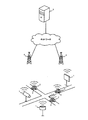
図1に示すように、本実施形態の無線通信システムは、車両制御システムとして機能し、無線通信が可能な複数の路側センサ1および車両2と、路側センサ1および車両2と無線通信する1または複数の基地局4と、基地局4とネットワークを介して有線または無線で通信するサーバ5とを備える。
As shown in FIG. 1, the wireless communication system of the present embodiment functions as a vehicle control system and wirelessly communicates with a plurality of
基地局4は、マクロセル基地局、マイクロセル基地局、およびピコセル基地局のうちの少なくとも1つよりなる。
The
本実施形態の無線通信システムにおいて、サーバ5は、例えば、SDN(Software-Defined Networking)が可能な汎用サーバよりなる。また、基地局4および図示しないリピータなどの中継装置は、SDNが可能なトランスポート機器によりなる。
In the wireless communication system of the present embodiment, the
上記のSDNに代表されるネットワーク仮想化技術は、現時点で規格化が進行中の「第5世代移動通信システム」(以下、「5G」(5th Generation)と略記する。)の基本コンセプトである。したがって、本実施形態の無線通信システムは、例えば5Gよりなる。 The network virtualization technology represented by the above SDN is a basic concept of the "fifth generation mobile communication system" (hereinafter, abbreviated as "5G" (5th Generation)), which is currently being standardized. Therefore, the wireless communication system of this embodiment is composed of, for example, 5G.
路側センサ1は、無線通信機能を有し、道路に設置された画像式車両感知器またはLiDAR、屋外または屋内に設置された防犯カメラなどの各種センサを含んで構成される。
The
車両2は、無線通信機能を有する車載装置3を含む。車載装置3は、カメラ、ミリ波レーダなどの各種センサ(以下、「車載センサ」という。)を含んで構成される。
The
車両2には、通常の乗用車だけでなく、路線バスや緊急車両などの公共車両も含まれる。また、車両2は、四輪車だけでなく、二輪車(バイク)であってもよい。
The
車両2の駆動方式は、エンジン駆動、電気モータ駆動、およびハイブリッド方式のいずれでもよい。車両2の運転方式は、搭乗者が加減速やハンドル操舵などの操作を行う通常運転、およびその操作をソフトウェアが実行する自動運転のいずれでもよい。
The drive system of the
[サーバの構成]
図2は、サーバ5の構成の一例を示すブロック図である。[Server configuration]
FIG. 2 is a block diagram showing an example of the configuration of the
図2に示すように、サーバ5は、情報生成装置として機能し、CPU(Central Processing Unit)などを含む制御部51と、ROM(Read Only Memory)55と、RAM(Random Access Memory)56と、記憶部57と、通信部58とを備える。
As shown in FIG. 2, the
制御部51は、ROM55に予め記憶された1または複数のプログラムをRAM56に読み出して実行することにより、各ハードウェアの動作を制御し、コンピュータ装置を基地局4と通信可能なサーバ5として機能させる。つまり、制御部51は、プログラムを実行することにより実現される機能な処理部として、センサ情報取得部52と、判断部53と、表示情報生成部54とを備える。
The
RAM56は、SRAM(Static RAM)またはDRAM(Dynamic RAM)などの揮発性のメモリ素子で構成され、制御部51が実行するプログラムおよびその実行に必要なデータを一時的に記憶する。
The
記憶部57は、フラッシュメモリ若しくはEEPROM(Electrically Erasable Programmable Read Only Memory)などの不揮発性のメモリ素子、または、ハードディスクなどの磁気記憶装置などにより構成されている。
The
通信部58は、5G対応の通信処理を実行する通信装置よりなり、ネットワークを介して基地局4と通信する。通信部58は、制御部51から与えられた情報を、ネットワークを介して外部装置に送信するとともに、ネットワークを介して受信した情報を制御部51に与える。
The
制御部51のセンサ情報取得部52は、所定の周期ごとに、サーバ5のサービスエリア内で車両2や路側センサ1などが計測した各種のセンサ情報を、車両2や路側センサ1などから取得する。つまり、センサ情報取得部52は、各センサから、当該センサの検出対象エリアの計測結果を示すセンサ情報を取得する。
The sensor
図3は、センサ情報取得部52が取得するセンサ情報の一例を示す図である。
例えば、路側には、路側センサ1としてミリ波レーダ(以下、「路側ミリ波レーダ」という。)1Mと、カメラ(以下、「路側カメラ」という。)1Cとが設置されているものとする。路側ミリ波レーダ1Mは、検出対象エリア7Mを監視し、検出対象エリア7M内で車両2Iを検出したものとする。一方、路側カメラ1Cは、検出対象エリア7Cを監視し、検出対象エリア7C内で車両2Jを検出したものとする。これにより、センサ情報取得部52は、路側ミリ波レーダ1Mから車両2Iの位置情報を含むセンサ情報を取得し、路側カメラ1Cから車両2Jの位置情報を含むセンサ情報を取得する。なお、図3には、路側センサ1を示しているが、車載センサであってもよい。また、路側センサ1として、LiDARや超音波センサなどを用いてもよい。FIG. 3 is a diagram illustrating an example of the sensor information acquired by the sensor
For example, assume that a millimeter wave radar (hereinafter, referred to as “road side millimeter wave radar”) 1M and a camera (hereinafter, referred to as “road side camera”) 1C are installed as the
制御部51の判断部53は、センサ情報取得部52が取得したセンサ情報に基づいて、複数のセンサの各々が同一の所定エリアに存在する対象物を検出しているか否かを判断する。
The
図3に示した例で車両2Iから所定距離以内のエリア8を所定エリアとした場合には、エリア8内に車両2Iおよび2Jが検出されている。このため、判断部53による上記の判断結果は肯定的である。なお、この所定エリアに含まれる車両は基本的に1台となるように、車両の大きさを考慮してこの所定距離を定めるとし、所定エリアに含まれる車両が複数か否かは判断部53によって判断している。
In the example shown in FIG. 3, when the area 8 within a predetermined distance from the vehicle 2I is the predetermined area, the
制御部51の表示情報生成部54は、判断部53の判断結果が肯定的であり、かつ所定の条件を満たさない場合に、複数のセンサの各々が検出した対象物を別個に表示するための第1表示情報を生成する。ここで、所定の条件とは、上記の所定エリア(エリア8)に存在する複数の対象物が同一の対象物であると判断するための条件である。所定の条件の詳細については後述する。つまり、表示情報生成部54は、所定エリア内に複数の対象物が検出され、当該複数の対象物が異なる対象物である場合に、それら複数の対象物を別々に表示するための第1表示情報を生成する。
The display
図4Aは、第1表示情報の一例を示す図である。第1表示情報においては、車両2Iと車両2Jとが別々に表示される。なお、第1表示情報および後述する第2表示情報において、各車両は、例えば、車両のアイコンで表示される。
FIG. 4A is a diagram showing an example of the first display information. In the first display information, the vehicle 2I and the
一方、表示情報生成部54は、判断部53の判断結果が肯定的であり、かつ上記所定の条件を満たす場合に、第1表示情報の表示態様とは異なる表示態様で複数のセンサの各々が検出した対象物を表示するための第2表示情報を生成する。つまり、表示情報生成部54は、所定エリア内に複数の対象物が検出され、当該複数の対象物が同一の対象物である場合に、それら複数の対象物を、第1表示情報の表示態様とは異なる表示態様で表示するための第2表示情報を生成する。
On the other hand, when the determination result of the
図4B〜図4Fの各々は、第2表示情報の一例を示す図である。
図4Bに示す第2表示情報においては、複数のセンサの各々が検出した対象物のうち、いずれか1つの対象物が表示される。つまり、当該第2表示情報では、図4Aの第1表示情報で示された車両2Iおよび車両2Jのうち、車両2Jが選択されて表示される。なお、車両2Iが選択されて表示されてもよい。表示対象の対象物はランダムに選択されてもよいし、以下に説明する基準に従い選択されてもよい。Each of FIGS. 4B to 4F is a diagram showing an example of the second display information.
In the second display information shown in FIG. 4B, any one of the objects detected by each of the plurality of sensors is displayed. That is, in the second display information, the
例えば、表示情報生成部54は、複数のセンサの種別に基づいて、複数の対象物のうちいずれか1つの対象物を選択してもよい。カメラやLiDARは高精度であるが、ミリ波レーダはそれらに比べて低精度である。このため、精度の高い順にセンサの優先順位を決めておき、表示情報生成部54は、優先順位が最も高いセンサが検出した対象物を選択するようにしてもよい。これにより、対象物を高精度で表示させることができる。ここで、サーバ5は、センサ種別とセンサIDとを対応付けるテーブルを参照して、センサ情報取得部52が取得したセンサ情報に含まれるセンサIDからセンサ種別を判断してもよい。なお、センサ情報にセンサの検出精度情報が付加されていてもよい。これにより、表示情報生成部54は、検出精度情報に基づいて、高い検出精度のセンサ情報を優先して、当該センサ情報に対応する対象物を選択することができる。
For example, the display
また、表示情報生成部54は、複数のセンサの設置対象に基づいて、複数の対象物のうちいずれか1つの対象物を選択してもよい。路側等に設置された路側センサ1は、車両2に設置された車載センサよりも検出精度が高い場合が多い。このため、表示情報生成部54は、路側センサ1が検出した対象物を、車載センサが検出した対象物よりも優先して選択する。これにより、対象物を高精度で表示させることができる。ここで、サーバ5は、センサの設置対象とセンサIDとを対応付けるテーブルを参照して、センサ情報取得部52が取得したセンサ情報に含まれるセンサIDからセンサの設置対象を判断してもよい。
In addition, the display
また、表示情報生成部54は、各センサから当該センサが検出した対象物までの距離に基づいて、複数の対象物のうちいずれか1つの対象物を選択してもよい。対象物までの距離が近いほどセンサの検出精度は高い。このため、表示情報生成部54は、対象物までの距離が最も近いセンサが検出した対象物を選択する。これにより、対象物を高精度で表示させることができる。
Further, the display
図4Cに示す第2表示情報においては、複数のセンサの各々が検出した対象物の平均の位置に1つの対象物が表示される。つまり、当該第2表示情報では、図4Aの第1表示情報で示された車両2Iおよび車両2Jの平均の位置に、車両2Lが表示される。位置を平均することにより、対象物の位置を正確な位置に近づけることができる。これにより、実際の対象物と同じ数の対象物を正確な位置に表示させることができる。
In the second display information shown in FIG. 4C, one target is displayed at the average position of the target detected by each of the plurality of sensors. That is, in the second display information, the
図4Dに示す第2表示情報においては、複数のセンサの各々が検出した対象物を統合した対象物が表示される。つまり、当該第2表示情報では、図4Aの第1表示情報で示された車両2Iおよび車両2Jの位置に、車両2Iおよび車両2Jをカバーするサイズの車両2Nが表示される。
In the second display information shown in FIG. 4D, the target object obtained by integrating the target objects detected by each of the plurality of sensors is displayed. That is, in the second display information, the vehicle 2I and the
図4Eに示す第2表示情報においては、複数のセンサの各々が検出した対象物が点滅しながら表示される。つまり、当該第2表示情報では、図4Aの第1表示情報で示された車両2Iおよび車両2Jが点滅しながら表示される。これにより、車両2Iおよび車両2Jが同一の車両2であることをユーザに知らせることができる。
In the second display information shown in FIG. 4E, the object detected by each of the plurality of sensors is displayed while blinking. That is, in the second display information, the
図4Fに示す第2表示情報においては、複数のセンサの各々が検出した対象物が、第1表示情報で示された対象物と異なる色で表示される。つまり、当該第2表示情報では、図4Aの第1表示情報で示された車両2Iおよび車両2Jが、それらとは異なる色で表示される。
In the second display information shown in FIG. 4F, the object detected by each of the plurality of sensors is displayed in a different color from the object shown in the first display information. That is, in the second display information, the vehicle 2I and the
表示情報生成部54は、例えば、図4B〜図4Fに示した少なくとも1つの表示態様の第2表示情報を作成する。なお、表示情報生成部54は、これらの表示態様を組み合わせた第2表示情報を作成することもできる。
The display
表示情報生成部54は、車両2の車載装置3や、ユーザが所持する通信端末から、表示情報の要求メッセージを受信すると、生成した表示情報を要求メッセージの送信元の車載装置3または通信端末に配信する。
When the display
次に、所定エリアに存在する複数の対象物が同一の対象物であると判断するための所定の条件について説明する。 Next, the predetermined condition for determining that the plurality of objects existing in the predetermined area are the same object will be described.
図5は、所定エリアに存在する複数の対象物が同一の対象物であると判断するための所定の条件について説明するための図である。 FIG. 5 is a diagram for explaining a predetermined condition for determining that a plurality of objects existing in a predetermined area are the same object.
所定の条件は、複数のセンサが検出した対象物の位置に基づく条件を含む。例えば、複数の対象物が同一の対象物である場合には、現在および過去のいずれにおいても、複数の対象物の位置は一致していると考えられる。一方、複数の対象物が異なる対象物である場合には、複数の対象物の現在の位置が一致していたとしても、過去において両者の位置は異なると考えられる。このため、表示情報生成部54は、現在時刻よりk秒前(kは正の値)の時刻において複数の対象物の位置が一致していれば、それらは同一の対象物であると判断し、一致していなければ、それらが別の対象物であると判断する。なお、厳密に対象物の位置が一致してなくても、対象物間の距離が所定の距離閾値以下である場合に両者の位置は一致しているとすることができる。なお、距離閾値は正の値である。
The predetermined condition includes a condition based on the positions of the object detected by the plurality of sensors. For example, when a plurality of target objects are the same target object, it is considered that the positions of the plurality of target objects are the same both in the present and in the past. On the other hand, when the plurality of objects are different objects, the positions of the two objects are considered to be different in the past even if the current positions of the objects are the same. For this reason, the display
図5に示すように、車両2Iは北向きに走行し、車両2Kは東向きに走行しているものとする。この場合、現在時刻tにおいて両者の位置は一致しているが、現在時刻tよりもk秒前の時刻(t−k)においては両者の位置は異なる。このため、表示情報生成部54は、車両2Kおよび車両2Jは別の車両であると判断する。
As shown in FIG. 5, it is assumed that the vehicle 2I is traveling north and the
所定の条件は、複数のセンサが検出した対象物の方向の差が所定の角度閾値以下であることを含んでいてもよい。つまり、表示情報生成部54は、方向の差が所定の角度閾値以下の場合に複数の対象物が同一であると判定し、方向の差が所定の角度閾値よりも大きい場合に複数の対象物が異なると判定する。なお、角度閾値は正の値である。図5に示す例では、車両2Iは、その位置変化から北向きに走行していると判断することができ、車両2Kは、その位置変化から東向きに走行していると判断することができる。このため、両者の方向の差は、およそ90°である。例えば角度閾値を5°とした場合には、表示情報生成部54は、車両2Kおよび車両2Jは別の車両であると判断する。
The predetermined condition may include that the difference between the directions of the objects detected by the plurality of sensors is equal to or smaller than a predetermined angle threshold. That is, the display
所定の条件は、複数のセンサが検出した対象物の速度の差が所定の速度閾値以下であることを含んでいてもよい。対象物の速度は、対象物の2地点間の距離および時間に基づいて算出される。速度閾値は正の値である。図5に示す例では、車両2Iおよび車両2Kの速度が、それぞれv1およびv2と算出されたものとする。表示情報生成部54は、速度v1およびv2の差の絶対値が所定の速度閾値以下の場合に、車両2Iおよび2Kが同一であると判断し、速度の差の絶対値が所定の速度閾値よりも大きい場合に、車両2Iおよび2Kが異なると判断する。
The predetermined condition may include that a difference between the speeds of the objects detected by the plurality of sensors is equal to or smaller than a predetermined speed threshold. The speed of the object is calculated based on the distance between the two points of the object and the time. The speed threshold is a positive value. In the example shown in FIG. 5, it is assumed that the speeds of the vehicle 2I and the
所定の条件は、複数のセンサが検出した対象物のサイズ、色および形状のうちの少なくとも1つに基づく条件を含んでいてもよい。例えば、センサがカメラの場合には、対象物のサイズ、色および形状を検知することができる。 The predetermined condition may include a condition based on at least one of the size, color, and shape of the object detected by the plurality of sensors. For example, when the sensor is a camera, the size, color and shape of the object can be detected.
このため、所定の条件は、複数のセンサが検出した対象物のサイズの差が、所定のサイズ閾値以下であることを含んでいてもよい。例えば、対象物のサイズを画像中で対象物が占める領域の画素数とした場合には、対象物に対応する領域の画素数の差が所定のサイズ閾値以下である場合に、所定の条件を満たすとしてもよい。 Therefore, the predetermined condition may include that the difference in size of the objects detected by the plurality of sensors is equal to or smaller than the predetermined size threshold. For example, if the size of the object is the number of pixels in the area occupied by the object in the image, and if the difference in the number of pixels in the area corresponding to the object is less than or equal to the predetermined size threshold, the predetermined condition is set. You may meet.
また、所定の条件は、複数のセンサが検出した対象物の色の差が所定の色閾値以下であることを含んでいてもよい。例えば、対象物のR,GおよびBの各色の輝度の平均値の差が色閾値以下の場合に、所定の条件を満たすとしてもよい。 Further, the predetermined condition may include that the difference in color between the objects detected by the plurality of sensors is equal to or smaller than a predetermined color threshold. For example, the predetermined condition may be satisfied when the difference in the average value of the brightness of each color of R, G, and B of the object is less than or equal to the color threshold.
さらに、所定の条件は、複数のセンサが検出した対象物の形状が類似することを含んでいてもよい。例えば、画像中の対象物の形状を矩形近似した場合に、対象物の形状を対象物に対応する矩形の長辺と短辺の比で示す。複数のセンサが検出した対象物に対応する上記比の差が所定の比閾値以下である場合に、所定の条件を満たすとしてもよい。 Further, the predetermined condition may include that the shapes of the objects detected by the plurality of sensors are similar. For example, when the shape of an object in an image is approximated to a rectangle, the shape of the object is indicated by the ratio of the long side to the short side of the rectangle corresponding to the object. The predetermined condition may be satisfied when the difference between the ratios corresponding to the objects detected by the plurality of sensors is equal to or smaller than a predetermined ratio threshold value.
対象物のサイズ、色または形状を用いて所定の条件を判断することにより、同一車線を走行する複数の車両または隣接する車線を並走する複数の車両を誤って1台の車両と判断することを防ぐことができる。これにより、所定エリアに存在する複数の対象物が同一の対象物か否かを正確に判定することができる。 By erroneously determining a plurality of vehicles traveling in the same lane or a plurality of vehicles traveling in parallel in adjacent lanes as one vehicle by determining a predetermined condition by using the size, color or shape of an object Can be prevented. This makes it possible to accurately determine whether or not a plurality of objects existing in the predetermined area are the same object.
なお、上述した各種の所定の条件を判断する際に用いられる速度閾値、角度閾値等の各種閾値は、複数のセンサの種別に基づいて定められてもよい。例えば、カメラやLiDARは高精度であるが、ミリ波レーダはそれらに比べて低精度である。このため、対象物を検出した複数のセンサの全てが高精度なセンサ(カメラまたはLiDAR)の場合には閾値を小さな値(第1閾値)に設定し、当該複数のセンサの中に低精度なセンサ(例えば、ミリ波レーダ)が含まれる場合には閾値を大きな値(第1閾値よりも大きい第2閾値)に設定してもよい。このように、センサの精度に応じて閾値を設定することで、所定エリアに存在する複数の対象物が同一の対象物か否かを正確に判定することができる。ここで、サーバ5は、センサ種別とセンサIDとを対応付けるテーブルを参照して、センサ情報取得部52が取得したセンサ情報に含まれるセンサIDからセンサ種別を判断してもよい。
Note that various thresholds such as a speed threshold and an angle threshold used when determining the various predetermined conditions described above may be determined based on the types of a plurality of sensors. For example, a camera and LiDAR have high accuracy, but a millimeter-wave radar has lower accuracy than them. Therefore, when all of the plurality of sensors that have detected the object are high-accuracy sensors (camera or LiDAR), the threshold value is set to a small value (first threshold value), and the low-accuracy sensor is used among the plurality of sensors. When a sensor (for example, a millimeter wave radar) is included, the threshold value may be set to a large value (second threshold value larger than the first threshold value). By thus setting the threshold value according to the accuracy of the sensor, it is possible to accurately determine whether or not a plurality of objects existing in a predetermined area are the same object. Here, the
また、上記の各種閾値は、複数のセンサの設置対象に基づいて定められてもよい。路側等に設置された路側センサ1は、車両2に設置された車載センサよりも検出精度が高い場合が多い。このため、複数の路側センサ1の各々が対象物を検出した場合には閾値を小さな値(第1閾値)に設定し、複数の車載センサの各々が対象物を検出した場合には閾値を大きな値(第1閾値よりも大きい第2閾値)に設定する。これにより、所定エリアに存在する複数の対象物が同一の対象物か否かを正確に判定することができる。ここで、サーバ5は、センサの設置対象とセンサIDとを対応付けるテーブルを参照して、センサ情報取得部52が取得したセンサ情報に含まれるセンサIDからセンサの設置対象を判断してもよい。
Further, the above-mentioned various thresholds may be set based on the installation targets of the plurality of sensors. The
また、上記の各種閾値は、複数のセンサの検出精度に基づいて定められてもよい。対象物を検出した複数のセンサの全てが高精度なセンサの場合には閾値を小さな値(第1閾値)に設定し、当該複数のセンサの中に低精度なセンサが含まれる場合には閾値を大きな値(第1閾値よりも大きい第2閾値)に設定してもよい。これにより、所定エリアに存在する複数の対象物が同一の対象物か否かを正確に判定することができる。ここで、サーバ5は、センサの検出精度とセンサIDとを対応付けるテーブルを参照して、センサ情報取得部52が取得したセンサ情報に含まれるセンサIDからセンサの検出精度を判断してもよい。
Further, the above various thresholds may be set based on the detection accuracy of the plurality of sensors. The threshold is set to a small value (first threshold) when all of the multiple sensors that have detected the object are high-precision sensors, and the threshold is set when the multiple sensors include low-precision sensors. May be set to a large value (second threshold value larger than the first threshold value). This makes it possible to accurately determine whether or not a plurality of objects existing in the predetermined area are the same object. Here, the
また、上記の各種閾値は、複数のセンサの位置精度に基づいて定められてもよい。路側等に設置された路側センサ1は固定されているため、車両2に設置された車載センサよりもセンサの位置精度が高い。対象物の絶対位置は、センサの絶対位置と、センサから対象物までの相対位置で規定することができる。このため、センサの絶対位置の検出精度が低い場合には、対象物の絶対位置の検出精度までも低くなる。つまり、センサの位置精度が高いほど、対象物の絶対位置の検出精度も高くなる。よって、対象物を検出した複数のセンサの全ての位置精度が高い場合には閾値を小さな値(第1閾値)に設定し、当該複数のセンサの中に位置精度が低いセンサが含まれる場合には閾値を大きな値(第1閾値よりも大きい第2閾値)に設定してもよい。これにより、所定エリアに存在する複数の対象物が同一の対象物か否かを正確に判定することができる。ここで、サーバ5は、センサの位置精度とセンサIDとを対応付けるテーブルを参照して、センサ情報取得部52が取得したセンサ情報に含まれるセンサIDからセンサの位置精度を判断してもよい。また、後述するように、センサ情報にセンサの位置精度情報が含まれていてもよい。
Further, the above-mentioned various thresholds may be set based on the positional accuracy of the plurality of sensors. Since the
[車載装置の構成]
図6は、車載装置3の構成の一例を示すブロック図である。[Configuration of in-vehicle device]
FIG. 6 is a block diagram showing an example of the configuration of the vehicle-mounted
図6に示すように、車両2の車載装置3は、制御部(ECU:Electronic Control Unit)31と、GPS(Global Positioning System)受信機32と、車速センサ33と、ジャイロセンサ34と、記憶部35と、ディスプレイ36と、スピーカ37と、入力デバイス38と、カメラ39と、ミリ波レーダ40と、通信部41とを備える。
As shown in FIG. 6, the vehicle-mounted
通信部41は、例えば5G対応の通信処理が可能な無線通信機よりなる。なお、通信部41は、車両2に既設の無線通信機であってもよいし、搭乗者が車両2に持ち込んだ携帯端末であってもよい。
The communication unit 41 is, for example, a wireless communication device capable of performing communication processing compatible with 5G. The communication unit 41 may be an existing wireless communication device in the
搭乗者の携帯端末は、車両2の車内LAN(Local Area Network)に接続されることにより、一時的に車載の無線通信機となる。
The portable terminal of the passenger is temporarily connected to an in-vehicle LAN (Local Area Network) of the
制御部31は、車両2の経路探索および他の電子機器32〜41の制御などを行うコンピュータ装置よりなる。制御部31は、GPS受信機32が定期的に取得するGPS信号により自車両の車両位置を求める。なお、制御部31は、図示しない準天頂衛星から送信される信号を受信する受信機が受信したGPS補完信号またはGPS補強信号を合わせて用いることで、GPS信号を補完したり、自車両の車両位置を補正したりしてもよい。
The
制御部31は、車速センサ33およびジャイロセンサ34の入力信号に基づいて、車両位置および方位を補完し、車両2の正確な現在位置および方位を把握する。
The
GPS受信機32、車速センサ33およびジャイロセンサ34は、車両2の現在位置、速度および向きを計測するセンサ類である。
The
記憶部35は、地図データベースを備える。地図データベースは、制御部31に道路地図データを提供する。道路地図データは、リンクデータやノードデータを含み、DVD、CD−ROM、メモリカード、またはHDDなどの記録媒体に格納されている。記憶部35は、記録媒体から必要な道路地図データを読み出して制御部31に提供する。
The
ディスプレイ36とスピーカ37は、制御部31が生成した各種情報を車両2の搭乗者であるユーザに通知するための出力装置である。
The
具体的には、ディスプレイ36は、経路探索の際の入力画面、自車周辺の地図画像および目的地までの経路情報などを表示する。スピーカ37は、車両2を目的地に誘導するためのアナウンスなどを音声出力する。これらの出力装置は、通信部41が受信した提供情報を搭乗者に通知することもできる。
Specifically, the
入力デバイス38は、車両2の搭乗者が各種の入力操作を行うためのデバイスである。入力デバイス38は、ハンドルに設けた操作スイッチ、ジョイスティック、およびディスプレイ36に設けたタッチパネルなどの組み合わせよりなる。
The
搭乗者の音声認識によって入力を受け付ける音声認識装置を、入力デバイス38とすることもできる。入力デバイス38が生成した入力信号は、制御部31に送信される。
The
カメラ39は、車両2の前方の映像を取り込む画像センサよりなる。カメラ39は、単眼または複眼のいずれでもよい。ミリ波レーダ40は、車両2の前方や周囲に存在する対象物を検出するセンサよりなる。なお、ミリ波レーダ40の代わりに、または、ミリ波レーダ40とともに、LiDARや、レーザレーダ、超音波レーダなどの各種センサを用いることができる。
The
制御部31は、カメラ39およびミリ波レーダ40による計測データや、サーバ5から取得したセンサ情報に基づいて、運転中の搭乗者に対する注意喚起をディスプレイ36に出力させたり、強制的なブレーキ介入を行ったりする運転支援制御を実行することができる。
Based on the measurement data obtained by the
制御部31は、記憶部35に格納された各種の制御プログラムを実行する、マイクロコンピュータなどの演算処理装置により構成されている。
The
制御部31は、上記制御プログラムを実行することにより、車両2の安全運転を支援する機能、ディスプレイ36に地図画像を表示させる機能、出発地から目的地までの経路(中継地がある場合はその位置を含む。)を算出する機能、算出した経路に従って車両2を目的地まで誘導する機能など、各種のナビゲーション機能を実行可能である。
The
制御部31は、カメラ39およびミリ波レーダ40のうちの少なくとも1つの計測データに基づいて、自車両の前方または周囲の対象物を認識する認識処理と、認識した対象物までの距離を算出する測距処理が可能である。
The
制御部31は、測距処理により算出した距離と、自車両のセンサ位置とから、認識処理によって認識した対象物の位置情報を算出することができる。
The
制御部31は、表示情報取得部31Aおよび表示制御部31Bを有し、サーバ5との通信において、以下の各処理を実行可能である。
1)要求メッセージの送信処理
2)表示情報の受信処理
3)通信パケットの送信処理The
1) Request message transmission processing 2) Display information reception processing 3) Communication packet transmission processing
要求メッセージの送信処理とは、表示情報取得部31Aが、サーバ5が生成する表示情報の配信を要求する制御パケットを、サーバ5に送信する処理のことである。制御パケットには、自車両の車両IDが含まれる。
The request message transmission process is a process in which the display
サーバ5は、所定の車両IDを含む要求メッセージを受信すると、送信元の車両IDを有する車両2の通信部41宛てに、表示情報を所定の配信周期で配信する。
When the
表示情報の受信処理とは、表示情報取得部31Aが、自装置に宛ててサーバ5が配信した表示情報を受信する処理のことである。
The display information reception process is a process in which the display
表示制御部31Bは、受信した表示情報をディスプレイ36に表示させるための処理を実行する。
The
例えば、表示制御部31Bは、受信した表示情報を地図画像に重畳し、ディスプレイ36に表示させる。
For example, the
車両2における通信パケットの送信処理とは、カメラ39またはミリ波レーダ40による対象物の検出結果を示すセンサ情報を含む通信パケットを、サーバ5宛に送信する処理のことである。通信パケットの送信処理は、サーバ5による表示情報の配信周期内に行われる。
The communication packet transmission process in the
センサ情報には、対象物の位置情報(対象物の緯度情報および経度情報)の他、車両2(カメラ39またはミリ波レーダ40)から対象物までの距離情報、車両2の位置情報(車両2の緯度情報よび経度情報)、車両2の速度情報、車両2の方位情報、センサの位置精度情報などが含まれる。センサの位置精度情報とは、つまり、車両2の位置精度を示す情報のことである。センサの位置精度情報は、例えば、以下に示す(a)〜(g)などにより定められる。
The sensor information includes position information of the target object (latitude information and longitude information of the target object), distance information from the vehicle 2 (
(a)DR(自律航法、ジャイロセンサ34や車速センサ33などの車速パルスやバック信号による位置の補正)の有無
(b)マップマッチングによる補正の有無
(c)記憶部35に記憶されている道路地図データの精度
(d)車両2の位置を求める際に用いたGPS衛星の数
(e)GPS受信機32のC/N0(搬送波雑音電力密度比)
(f)GPSクオリティ
(g)PDOP(位置精度低下率)(A) Presence / absence of DR (autonomous navigation, position correction by vehicle speed pulse or back signal of
(F) GPS quality (g) PDOP (position accuracy deterioration rate)
制御部31は、通信パケットに自車両の車両IDを含めて、サーバ5宛に送信する。
The
[路側センサの構成]
図7は、路側センサ1の構成の一例を示すブロック図である。[Road side sensor configuration]
FIG. 7 is a block diagram showing an example of the configuration of the
図7に示すように、路側センサ1は、制御部11と、記憶部12と、カメラ13と、ミリ波レーダ14と、通信部15とを備える。
As shown in FIG. 7, the
通信部15は、例えば5G対応の通信処理が可能な無線通信機よりなる。
The
したがって、路側センサ1は、サーバ5と通信することができる。
Therefore, the
制御部11は、CPU、ROM及びRAMなどを含む。制御部11は、記憶部12に記憶されたプログラムを読み出して実行し、路側センサ1の全体の動作を制御する。
The
記憶部12は、ハードディスクや不揮発性のメモリなどより構成され、各種のコンピュータプログラムやデータを記憶する。記憶部12は、路側センサ1の識別情報であるセンサIDを記憶している。センサIDは、例えば、路側センサ1の所有者固有のユーザIDやMACアドレスなどよりなる。
The
カメラ13は、所定の撮影エリアの映像を取り込む画像センサよりなる。カメラ13は、単眼又は複眼のいずれでもよい。ミリ波レーダ14は、ミリ波レーダ14の前方や周囲に存在する対象物を検出するセンサよりなる。なお、ミリ波レーダ14の代わりに、または、ミリ波レーダ14とともに、LiDARや、レーザレーダ、超音波レーダなどの各種センサを用いることができる。
The
また、路側センサ1には、カメラ13およびミリ波レーダ14のいずれか1つのみが備えられていてもよい。
Further, the
制御部11は、カメラ13及びミリ波レーダ14のうちの少なくとも1つの計測データに基づいて、撮影エリア内の対象物を認識する認識処理と、認識した対象物までの距離を算出する測距処理が可能である。
The
制御部11は、測距処理により算出した距離と、自車両のセンサ位置とから、認識処理によって認識した対象物の位置情報を算出することができる。
The
制御部11は、サーバ5との通信において、通信パケットの送信処理を実行可能である。
The
路側センサ1による通信パケットの送信処理とは、カメラ13またはミリ波レーダ14による対象物の検出結果を示すセンサ情報を含む通信パケットを、サーバ5宛に送信する処理のことである。通信パケットの送信処理は、サーバ5による表示情報の配信周期内に行われる。
The transmission process of the communication packet by the
センサ情報には、対象物の位置情報(対象物の緯度情報および経度情報)や、路側センサ1から対象物までの距離情報などが含まれる。
制御部11は、通信パケットにセンサIDを含めて、サーバ5宛に送信する。The sensor information includes position information of the target object (latitude information and longitude information of the target object), distance information from the
The
[表示情報の配信処理]
図8は、車載装置3、車載カメラ2C、車載ミリ波レーダ2M、路側カメラ1C、路側ミリ波レーダ1M、およびサーバ5の協働により実行される、表示情報の配信処理の一例を示すシーケンス図である。図8に示されるシーケンスを所定間隔(例えば、100msec間隔)で繰り返すことにより、所定間隔で安全運転支援のための機能が選択され、配信される。[Distribution processing of display information]
FIG. 8 is a sequence diagram showing an example of display information distribution processing executed by the cooperation of the vehicle-mounted
ここで、車載装置3は、表示情報の提供を受ける車両2に設置された車載装置を示す。車載カメラ2Cは、カメラ39を備える車載装置3を示す。車載ミリ波レーダ2Mは、ミリ波レーダ40を備える車載装置3を示す。路側カメラ1Cは、カメラ13を備える路側センサ1を示す。路側ミリ波レーダ1Mは、ミリ波レーダ14を備える路側センサ1を示す。ただし、これらのセンサは、一例であり、いずれかのセンサが含まれていなくてもよいし、これ以外のセンサが含まれていてもよい。
Here, the in-
以下では、各センサが検出する対象物は移動物体であるとして説明を行うが、検出対象物は静止物体であってもよい。 In the following, the object detected by each sensor is described as a moving object, but the object to be detected may be a stationary object.
車載カメラ2Cは、カメラ39が撮像した映像データに基づいて、車載カメラ2Cを備える車両2の前方または周囲を走行する車両2または歩行者6などの移動物体を検出する(S1)。
The vehicle-mounted camera 2C detects a moving object such as the
車載ミリ波レーダ2Mは、ミリ波レーダ40の計測データに基づいて、ミリ波レーダ40を備える車両2の前方または周囲を走行する車両2または歩行者6などの移動物体を検出する(S2)。
The in-vehicle
路側カメラ1Cは、カメラ13が撮像した映像データに基づいて、路側カメラ1Cの前方または周囲を走行する他の車両2または歩行者6などの移動物体を検出する(S3)。
The
路側ミリ波レーダ1Mは、ミリ波レーダ14の計測データに基づいて、路側ミリ波レーダ1Mの前方または周囲を走行する他の車両2または歩行者6などの移動物体を検出する(S4)。
The roadside
車載カメラ2Cは、移動物体の検出結果を含むセンサ情報を含む通信パケットを、サーバ5に送信する(S5)。サーバ5は、車載カメラ2Cから送信された通信パケットを受信する。
The vehicle-mounted camera 2C transmits a communication packet including sensor information including the detection result of the moving object to the server 5 (S5). The
車載ミリ波レーダ2Mは、移動物体の検出結果を含むセンサ情報を含む通信パケットを、サーバ5に送信する(S6)。サーバ5は、車載ミリ波レーダ2Mから送信された通信パケットを受信する。
The in-vehicle millimeter-
路側カメラ1Cは、移動物体の検出結果を含むセンサ情報を含む通信パケットを、サーバ5に送信する(S7)。サーバ5は、路側カメラ1Cから送信された通信パケットを受信する。
The
路側ミリ波レーダ1Mは、移動物体の検出結果を含むセンサ情報を含む通信パケットを、サーバ5に送信する(S8)。サーバ5は、路側ミリ波レーダ1Mから送信された通信パケットを受信する。
The roadside
サーバ5は、車載カメラ2C、車載ミリ波レーダ2M、路側カメラ1Cおよび路側ミリ波レーダ1Mからそれぞれ受信した通信パケットに含まれるセンサ情報に基づいて、各センサが検出した移動物体を示した表示情報を生成する(S9)。表示情報(後述の第1表示情報、第2表示情報または第3表示情報)の生成処理(ステップS9)については後述する。
The
車載装置3は、表示情報の配信を要求する制御パケットを要求メッセージとしてサーバ5に送信する(S10)。
The vehicle-mounted
サーバ5は、車載装置3から要求メッセージを受け取り、要求メッセージの送信元である車載装置3に対して、表示情報生成処理(ステップS9)で生成された表示情報を送信する(S11)。車両2の車載装置3は、当該表示情報を受信し、受信した表示情報をディスプレイ36に表示させるための処理を実行する。
The
[表示情報生成処理(図8のステップS9)]
表示情報生成処理(図8のステップS9)の詳細について、説明する。[Display Information Generation Processing (Step S9 in FIG. 8)]
Details of the display information generation process (step S9 in FIG. 8) will be described.
図9は、表示情報生成処理(図8のステップS9)の詳細を示すフローチャートである。 FIG. 9 is a flowchart showing details of the display information generation process (step S9 in FIG. 8).
図9を参照して、サーバ5の判断部53は、センサ情報取得部52が取得したセンサ情報に基づいて、あるセンサが検出した移動物体(以下、「第1物体」という。)から所定距離範囲内に他のセンサが検出した移動物体(以下、「第2物体」という。)が存在するか否かを判断する(S21)。図3を参照して、第1物体を車両2Iとし、所定距離範囲をエリア8とした場合、第1物体から所定距離範囲内に第2物体である車両2Jが存在することとなる。
Referring to FIG. 9,
ステップS21の判断結果が肯定的である場合には(S21でYES)、表示情報生成部54は、現在時刻よりk秒前(kは正の値)の時刻において第1物体および第2物体の位置が一致しているか否かを判断する(S22)。つまり、表示情報生成部54は、現在時刻よりもk秒前の第1物体および第2物体間の距離が所定の距離閾値以下である場合に両者の位置が一致していると判断し、当該距離が距離閾値よりも大きい場合に両者の位置が一致していないと判断する。図5は、k秒前の位置が一致していない車両2Kおよび車両2Iを示している。
When the determination result of step S21 is affirmative (YES in S21), the display
第1物体および第2物体のk秒前の位置が一致している場合には(S22でYES)、表示情報生成部54は、第1物体および第2物体の進行方向が一致しているか否かを判断する(S23)。つまり、表示情報生成部54は、第1物体および第2物体の方向の差が所定の角度閾値以下である場合に進行方向が一致していると判断し、当該方向の差が角度閾値よりも大きい場合に進行方向が一致していないと判断する。図5は、進行方向が一致していない車両2Kおよび車両2Iを示している。
When the positions of the first object and the second object k seconds ago match (YES in S22), the display
第1物体および第2物体の進行方向が一致している場合には(S23でYES)、表示情報生成部54は、第1物体および第2物体の速度が一致しているか否かを判断する(S24)。つまり、表示情報生成部54は、第1物体および第2物体の速度の差の絶対値が所定の速度閾値以下の場合に、両者の速度が一致していると判断し、速度の差の絶対値が速度閾値よりも大きい場合に、両者の速度が異なると判断する(S24)。
When the traveling directions of the first object and the second object match (YES in S23), the display
第1物体および第2物体の速度が一致している場合には(S24でYES)、表示情報生成部54は、第1物体および第2物体が同一の移動物体であると判断し、第1物体および第2物体を統合して表示するための第2表示情報を生成する(S25)。第2表示情報の例は、図4B〜図4Dに示した通りである。なお、第2表示情報は、図4Eまたは図4Fに示したような第1物体および第2物体を統合せずに表示するための表示情報であってもよい。
When the velocities of the first object and the second object match (YES in S24), the display
ステップS22〜24のいずれかの判断結果が否定的である場合には(S22でNO、S23でNOまたはS24でNO)、表示情報生成部54は、第1物体および第2物体が異なる移動物体であると判断し、第1物体および第2物体をそれぞれ表示する第1表示情報を生成する(S26)。第1表示情報の例は、図4Aに示した通りである。
When the determination result of any of steps S22 to S24 is negative (NO in S22, NO in S23, or NO in S24), the display
第1物体から所定距離範囲内に第2物体が存在しない場合には(S21でNO)、表示情報生成部54は、第1表示物体を表示するための第3表示情報を生成する(S27)。
When the second object does not exist within the predetermined distance range from the first object (NO in S21), the display
[実施形態の効果]
以上説明したように、本発明の実施形態によると、複数のセンサの各々が所定エリアに存在する対象物を検出している場合に、所定条件を満たす場合と満たさない場合とで、対象物の表示態様を変化させることができる。例えば、複数の対象物が異なる対象物である場合に複数の対象物を別個に表示させ、複数の対象物が同一の対象物である場合に、上記表示とは異なる表示態様で複数の対象物を表示させることができる。これにより、複数の対象物が異なる対象物と判断されたのか、同一の対象物と判断されたのかの別をユーザは知ることができる。これにより、複数のセンサ情報から、適切な表示情報を生成することができる。[Effect of Embodiment]
As described above, according to the embodiment of the present invention, when each of the plurality of sensors detects an object existing in a predetermined area, the target object may or may not be satisfied. The display mode can be changed. For example, when the plurality of objects are different objects, the plurality of objects are displayed separately, and when the plurality of objects are the same object, the plurality of objects are displayed in a display mode different from the above display. Can be displayed. As a result, the user can know whether the plurality of objects are determined to be different objects or the same object. Accordingly, it is possible to generate appropriate display information from the plurality of sensor information.
(変形例)
なお、上述した実施形態では、センサが検出した対象物の位置に制限を設けていなかったが、対象物の位置に制限を設けるようにしてもよい。(Modification)
In the above-described embodiment, the position of the object detected by the sensor is not limited, but the position of the object may be limited.
つまり、サーバ5の判断部53は、各センサと、各センサが検出した対象物との位置関係に基づいて、検出した対象物を判断対象とするか否かを決定してもよい。
That is, the
図10は、対象物を判断対象とするか否かの判断基準を示すための図である。
図10に示す車載カメラの検出範囲、車載ミリ波レーダの検出範囲および車載LiDARの検出範囲は、各センサによる対象物の検出精度が高い範囲を示している。つまり、各センサは、検出範囲外の対象物も検出可能ではあるが、検出範囲外では対象物の検出精度が低い。なお、図10に示す検出範囲は一例であり、各センサの検出精度により変化する。たとえば、4Kの車載カメラに比べ8Kの車載カメラの方が検出範囲は広くなることが想定される。FIG. 10 is a diagram showing a criterion for determining whether or not an object is a determination target.
The detection range of the vehicle-mounted camera, the detection range of the vehicle-mounted millimeter-wave radar, and the detection range of the vehicle-mounted LiDAR shown in FIG. 10 indicate ranges in which the detection accuracy of the target object by each sensor is high. That is, each sensor can detect an object outside the detection range, but the detection accuracy of the object is low outside the detection range. The detection range shown in FIG. 10 is an example, and changes depending on the detection accuracy of each sensor. For example, it is assumed that the 8K vehicle-mounted camera has a wider detection range than the 4K vehicle-mounted camera.
図10を参照して、判断部53は、車載ミリ波レーダが検出した対象物が車載ミリ波レーダの前方に設定された車載ミリ波レーダの検出範囲に含まれる場合には、当該対象物を判断対象とし、対象物が当該検出範囲に含まれない場合には、当該対象物を判断対象から外す。
With reference to FIG. 10, when the object detected by the on-vehicle millimeter-wave radar is included in the detection range of the on-vehicle millimeter-wave radar set in front of the on-vehicle millimeter-wave radar, the
また、判断部53は、車載カメラが検出した対象物が車載カメラの前方もしくは周囲に設定された車載カメラの検出範囲に含まれる場合には、当該対象物を判断対象とし、対象物が当該検出範囲に含まれない場合には、当該対象物を判断対象から外す。
In addition, when the target detected by the vehicle-mounted camera is included in the detection range of the vehicle-mounted camera set in front of or in the vicinity of the vehicle-mounted camera, the
さらに、判断部53は、車載LiDARが検出した対象物が車載LiDARの前方もしくは周囲に設定された車載LiDARの検出範囲に含まれる場合には、当該対象物を判断対象とし、対象物が当該検出範囲に含まれない場合には、当該対象物を判断対象から外す。
Furthermore, when the target detected by the vehicle-mounted LiDAR is included in the detection range of the vehicle-mounted LiDAR set in front of or in the vicinity of the vehicle-mounted LiDAR, the
これにより、判断部53は、検出精度が高い対象物のみを判断対象として、判断対象とされた対象物から所定距離以内に他の対象物が存在する場合に、両対象物が同一か否かの判断を行う。
Thus, the
本変形例によると、対象物までの距離が近い場合にのみ、所定エリアに存在する複数の対象物が同一の対象物か否かを判定することができる。これにより、センサから遠方に位置する検出精度の低い対象物に対しては判定処理を行わずに、検出精度の高い対象物に対してのみ判定処理を行うようにすることができる。これにより、判定処理の信頼性を高めることができ、所定エリアに存在する複数の対象物が同一の対象物か否かを正確に判定することができる。 According to this modification, it is possible to determine whether or not a plurality of objects existing in a predetermined area are the same object only when the distance to the object is short. As a result, it is possible to perform the determination process only on an object with a high detection accuracy, without performing the determination process on an object with a low detection accuracy that is located far from the sensor. Thereby, the reliability of the determination process can be improved, and it can be accurately determined whether or not a plurality of objects existing in the predetermined area are the same object.
なお、図10では、車載センサの検出範囲を示したが、路側センサの検出範囲も同様に設定されており、判断部53は、車載センサの場合と同様の処理により路側センサが検出した対象物を判断対象とするか否かを判断することができる。
Although the detection range of the vehicle-mounted sensor is shown in FIG. 10, the detection range of the roadside sensor is also set in the same manner, and the
以上、本発明の実施形態に係る無線通信システムについて説明したが、本発明は、この実施形態に限定されるものではない。 Although the wireless communication system according to the embodiment of the present invention has been described above, the present invention is not limited to this embodiment.
例えば、上記した無線通信システムは、以下の付記1に示す情報生成装置として実現することもできる。
For example, the wireless communication system described above can also be realized as an information generating device shown in the
[付記1]
各センサから、検出対象エリアの計測結果を示すセンサ情報を取得するセンサ情報取得部と、
上記センサ情報取得部が取得した上記センサ情報に基づいて、複数のセンサの各々が同一の所定エリアに存在する対象物を検出しているか否かを判断する判断部と、
上記判断部の判断結果が肯定的であり、かつ上記複数のセンサが検出した上記対象物が同一の対象物か否かを判断するための所定の条件を満たさない場合に、上記複数のセンサの各々が検出した上記対象物を別個に表示するための第1表示情報を生成し、上記判断結果が肯定的であり、かつ上記所定の条件を満たす場合に、上記第1表示情報の表示態様とは異なる表示態様で上記複数のセンサの各々が検出した上記対象物を表示するための第2表示情報を生成する表示情報生成部と、を備え、
上記第2表示情報は、上記複数のセンサの各々が検出した上記対象物を上記第1表示情報で示された対象物と異なる色で表示するための情報を含む、情報生成装置。[Appendix 1]
From each sensor, a sensor information acquisition unit that acquires sensor information indicating the measurement result of the detection target area,
Based on the sensor information acquired by the sensor information acquisition unit, a determination unit that determines whether or not each of the plurality of sensors is detecting an object existing in the same predetermined area,
If the determination result of the determination unit is positive, and the objects detected by the plurality of sensors do not satisfy the predetermined condition for determining whether the objects are the same object, the plurality of sensors When the first display information for individually displaying the detected objects is generated and the determination result is affirmative and the predetermined condition is satisfied, a display mode of the first display information and A display information generation unit that generates second display information for displaying the object detected by each of the plurality of sensors in different display modes,
The second display information is an information generating device including information for displaying the object detected by each of the plurality of sensors in a color different from that of the object indicated by the first display information.
また、上述の実施形態では、表示情報生成部54が、所定の条件を満たすか否かを判断することにより、所定エリアに存在する複数の対象物が同一の対象物であるか否かを判断していた。ただし、表示情報生成部54ではなく、判断部53が、所定の条件を満たすか否かを判断してもよい。
Further, in the above-described embodiment, the display
また、上記の各装置を構成する構成要素の一部または全部は、1個のシステムLSIから構成されているとしてもよい。システムLSIは、複数の構成部を1個のチップ上に集積して製造された超多機能LSIであり、具体的には、マイクロプロセッサ、ROM、RAMなどを含んで構成されるコンピュータシステムである。RAMには、コンピュータプログラムが記憶されている。マイクロプロセッサが、コンピュータプログラムに従って動作することにより、システムLSIは、その機能を達成する。 Further, some or all of the constituent elements of each of the above devices may be configured by one system LSI. The system LSI is a super-multifunctional LSI manufactured by integrating a plurality of components on a single chip, and specifically, is a computer system including a microprocessor, ROM, RAM and the like. . A computer program is stored in the RAM. The system LSI achieves its function by the microprocessor operating according to the computer program.
また、本発明は、上記に示す方法であるとしてもよい。また、本発明は、これらの方法をコンピュータにより実現するコンピュータプログラムであるとしてもよい。 Further, the present invention may be the methods described above. Further, the present invention may be a computer program that realizes these methods by a computer.
さらに、本発明は、上記コンピュータプログラムをコンピュータ読取可能な非一時的な記録媒体、例えば、HDD、CD−ROM、半導体メモリなどに記録したものとしてもよい。 Furthermore, the present invention may be a computer-readable non-transitory recording medium, such as an HDD, a CD-ROM, or a semiconductor memory, in which the above computer program is recorded.
また、本発明は、上記コンピュータプログラムを、電気通信回線、無線または有線通信回線、インターネットを代表とするネットワーク、データ放送等を経由して伝送するものとしてもよい。 Further, the present invention may be the computer program transmitted via an electric communication line, a wireless or wired communication line, a network typified by the Internet, data broadcasting and the like.
また、上記実施形態および上記変形例の少なくとも一部を任意に組み合わせるとしてもよい。 In addition, at least a part of the above-described embodiment and the above-described modified example may be arbitrarily combined.
今回開示された実施形態はすべての点で例示であって制限的なものではないと考えられるべきである。本発明の範囲は、上記した意味ではなく、請求の範囲によって示され、請求の範囲と均等の意味および範囲内でのすべての変更が含まれることが意図される。 The embodiments disclosed this time are to be considered as illustrative in all points and not restrictive. The scope of the present invention is shown not by the meanings described above but by the claims, and is intended to include meanings equivalent to the claims and all modifications within the scope.
1 路側センサ
1C 路側カメラ
1M 路側ミリ波レーダ
2 車両
2C 車載カメラ
2I 車両
2J 車両
2K 車両
2L 車両
2M 車載ミリ波レーダ
2N 車両
3 車載装置
4 基地局
5 サーバ
6 歩行者
7C 検出対象エリア
7M 検出対象エリア
8 エリア
11 制御部
12 記憶部
13 カメラ
14 ミリ波レーダ
15 通信部
31 制御部
31A 表示情報取得部
31B 表示制御部
32 GPS受信機
33 車速センサ
34 ジャイロセンサ
35 記憶部
36 ディスプレイ
37 スピーカ
38 入力デバイス
39 カメラ
40 ミリ波レーダ
41 通信部
51 制御部
52 センサ情報取得部
53 判断部
54 表示情報生成部
55 ROM
56 RAM
57 記憶部
58 通信部1
56 RAM
57
Claims (22)
前記センサ情報取得部が取得した前記複数のセンサ情報に基づいて、前記複数のセンサの各々が同一の所定エリアに存在する対象物を検出しているか否かを判断する判断部と、
前記判断部の判断結果が肯定的であり、かつ前記複数のセンサが検出した前記対象物が同一の対象物か否かを判断するための所定の条件を満たさない場合に、前記複数のセンサの各々が検出した前記対象物を別個に表示するための第1表示情報を生成し、前記判断結果が肯定的であり、かつ前記所定の条件を満たす場合に、前記第1表示情報の表示態様とは異なる表示態様で前記複数のセンサの各々が検出した前記対象物を表示するための第2表示情報を生成する表示情報生成部と
を備える情報生成装置。 From each of a plurality of sensors having a detection target area common to each other, a sensor information acquisition unit that acquires sensor information indicating the measurement result of the detection target area,
Based on the plurality of sensor information acquired by the sensor information acquisition unit, a determination unit that determines whether each of the plurality of sensors is detecting an object existing in the same predetermined area,
If the determination result of the determination unit is affirmative, and the objects detected by the plurality of sensors do not satisfy the predetermined condition for determining whether or not the objects are the same object, the plurality of sensors When the first display information for individually displaying the detected objects is generated and the determination result is affirmative and the predetermined condition is satisfied, a display mode of the first display information and And a display information generation unit that generates second display information for displaying the object detected by each of the plurality of sensors in different display modes.
請求項1に記載の情報生成装置。 The information generating apparatus according to claim 1, wherein an area within a predetermined distance from a position of an object based on sensor information obtained from one of the plurality of sensors is set as the predetermined area.
請求項1又は請求項2に記載の情報生成装置。 The information generating device according to claim 1, wherein the second display information includes information for displaying any one of the objects detected by each of the plurality of sensors. .
請求項3に記載の情報生成装置。 The display information generation unit generates the second display information for displaying the selected target object by selecting any one of the target objects based on the types of the plurality of sensors. The information generation device according to item 3.
請求項3に記載の情報生成装置。 The display information generation unit generates the second display information for displaying the selected target object by selecting any one of the target objects based on installation targets of the plurality of sensors. Item 3. The information generation device according to item 3.
請求項3に記載の情報生成装置。 The display information generation unit is for displaying the selected target object by selecting any one of the target objects based on a distance from each sensor to the target object detected by each sensor. The information generation device according to claim 3, wherein the second display information is generated.
請求項1又は請求項2に記載の情報生成装置。 The information generating apparatus according to claim 1, wherein the second display information includes information for displaying an object obtained by integrating the objects detected by each of the plurality of sensors.
請求項1又は請求項2に記載の情報生成装置。 The information generation device according to claim 1 or 2, wherein the second display information includes information for blinking and displaying the object detected by each of the plurality of sensors.
請求項1又は請求項2に記載の情報生成装置。 The information generation device according to claim 1, wherein the second display information includes information for displaying one target object at an average position of the target object detected by each of the plurality of sensors.
請求項1〜請求項9のいずれか1項に記載の情報生成装置。 The information generating apparatus according to claim 1, wherein the predetermined condition includes a condition based on positions of the target object detected by the plurality of sensors.
請求項10に記載の情報生成装置。 The information generating apparatus according to claim 10, wherein the predetermined condition includes that a distance between the objects detected by the plurality of sensors at a predetermined time in the past is equal to or less than a predetermined distance threshold.
請求項1〜請求項11のいずれか1項に記載の情報生成装置。 The information generating apparatus according to claim 1, wherein the predetermined condition includes that a difference between the directions of the objects detected by the plurality of sensors is equal to or smaller than a predetermined angle threshold.
請求項1〜請求項12のいずれか1項に記載の情報生成装置。 The information generating apparatus according to claim 1, wherein the predetermined condition includes that a difference in speed of the object detected by the plurality of sensors is equal to or smaller than a predetermined speed threshold.
請求項11〜請求項13のいずれか1項に記載の情報生成装置。 The information generation device according to claim 11, wherein each of the thresholds is determined based on a type of the plurality of sensors.
請求項11〜請求項13のいずれか1項に記載の情報生成装置。 The information generation device according to any one of claims 11 to 13, wherein each of the thresholds is determined based on installation targets of the plurality of sensors.
請求項11〜請求項13のいずれか1項に記載の情報生成装置。 The information generation device according to claim 11, wherein each of the thresholds is determined based on detection accuracy of the plurality of sensors.
請求項11〜請求項13のいずれか1項に記載の情報生成装置。 The information generation device according to claim 11, wherein each of the thresholds is determined based on positional accuracy of the plurality of sensors.
請求項1〜請求項17のいずれか1項に記載の情報生成装置。 The information generation according to any one of claims 1 to 17, wherein the predetermined condition includes a condition based on at least one of the size, color, and shape of the object detected by the plurality of sensors. apparatus.
請求項1〜請求項18のいずれか1項に記載の情報生成装置。 The said determination part determines whether the detected said target object is made into a determination object based on the positional relationship of each said sensor and the said target object which each said sensor detected. The information generation device according to any one of items.
取得された前記複数のセンサ情報に基づいて、前記複数のセンサの各々が同一の所定エリアに存在する対象物を検出しているか否かを判断するステップと、
前記判断するステップにおける判断結果が肯定的であり、かつ前記複数のセンサが検出した前記対象物が同一の対象物か否かを判断するための所定の条件を満たさない場合に、前記複数のセンサの各々が検出した前記対象物を別個に表示するための第1表示情報を生成し、前記判断結果が肯定的であり、かつ前記所定の条件を満たす場合に、前記第1表示情報の表示態様とは異なる表示態様で前記複数のセンサの各々が検出した前記対象物を表示するための第2表示情報を生成するステップと
を含む情報生成方法。 From each of a plurality of sensors having a detection target area common to each other, a step of acquiring sensor information indicating a measurement result of the detection target area,
Based on the acquired sensor information, a step of determining whether or not each of the plurality of sensors is detecting an object present in the same predetermined area,
If the determination result in the determining step is affirmative, and the objects detected by the plurality of sensors do not satisfy a predetermined condition for determining whether the objects are the same object, the plurality of sensors Of the first display information for individually displaying the detected objects detected by each of the first and second display information, when the determination result is positive and the predetermined condition is satisfied, the display mode of the first display information And a step of generating second display information for displaying the object detected by each of the plurality of sensors in a display mode different from the above.
互いに共通する検出対象エリアを持つ複数のセンサの各々から、検出対象エリアの計測結果を示すセンサ情報を取得するセンサ情報取得部、
前記センサ情報取得部が取得した前記複数のセンサ情報に基づいて、前記複数のセンサの各々が同一の所定エリアに存在する対象物を検出しているか否かを判断する判断部、及び
前記判断部の判断結果が肯定的であり、かつ前記複数のセンサが検出した前記対象物が同一の対象物か否かを判断するための所定の条件を満たさない場合に、前記複数のセンサの各々が検出した前記対象物を別個に表示するための第1表示情報を生成し、前記判断結果が肯定的であり、かつ前記所定の条件を満たす場合に、前記第1表示情報の表示態様とは異なる表示態様で前記複数のセンサの各々が検出した前記対象物を表示するための第2表示情報を生成する表示情報生成部
として機能させるためのコンピュータプログラム。 Computer,
From each of the plurality of sensors having a common detection target area, a sensor information acquisition unit that acquires sensor information indicating the measurement result of the detection target area,
Based on the plurality of sensor information acquired by the sensor information acquisition unit, a determination unit that determines whether each of the plurality of sensors is detecting an object existing in the same predetermined area, and the determination unit If the determination result is affirmative and the objects detected by the plurality of sensors do not satisfy a predetermined condition for determining whether the objects are the same object, each of the plurality of sensors detects When the determination result is positive and the predetermined condition is satisfied and the first display information for separately displaying the target object is generated, a display different from the display mode of the first display information is displayed. A computer program for causing a display information generation unit that generates second display information for displaying the object detected by each of the plurality of sensors in an aspect.
前記情報生成装置とネットワークを介して接続される車載装置とを備え、An in-vehicle device connected to the information generation device via a network,
前記車載装置は、The in-vehicle device is
前記情報生成装置から、当該情報生成装置が生成した前記第1表示情報および第2表示情報のうちの少なくとも1つの表示情報を取得する表示情報取得部と、A display information acquisition unit that acquires, from the information generation device, at least one display information item of the first display information item and the second display information item generated by the information generation device item;
前記表示情報取得部が取得した前記表示情報に基づく画面への表示を制御する表示制御部とを含む、A display control unit that controls display on a screen based on the display information acquired by the display information acquisition unit;
無線通信システム。Wireless communication system.
Applications Claiming Priority (3)
| Application Number | Priority Date | Filing Date | Title |
|---|---|---|---|
| JP2018022896 | 2018-02-13 | ||
| JP2018022896 | 2018-02-13 | ||
| PCT/JP2018/044111 WO2019159494A1 (en) | 2018-02-13 | 2018-11-30 | Information generation device, information generation method, computer program and on-board device |
Publications (2)
| Publication Number | Publication Date |
|---|---|
| JP6687169B2 true JP6687169B2 (en) | 2020-04-22 |
| JPWO2019159494A1 JPWO2019159494A1 (en) | 2020-05-28 |
Family
ID=67619888
Family Applications (1)
| Application Number | Title | Priority Date | Filing Date |
|---|---|---|---|
| JP2019559853A Active JP6687169B2 (en) | 2018-02-13 | 2018-11-30 | Information generating device, information generating method, computer program, and wireless communication system |
Country Status (5)
| Country | Link |
|---|---|
| US (1) | US11010612B2 (en) |
| JP (1) | JP6687169B2 (en) |
| CN (1) | CN111699523B (en) |
| DE (1) | DE112018007073T5 (en) |
| WO (1) | WO2019159494A1 (en) |
Families Citing this family (7)
| Publication number | Priority date | Publication date | Assignee | Title |
|---|---|---|---|---|
| JP6789440B2 (en) * | 2018-03-30 | 2020-11-25 | 三菱電機株式会社 | Object identification device |
| JP7044000B2 (en) * | 2018-07-20 | 2022-03-30 | 株式会社デンソー | Vehicle control device and vehicle control method |
| US11808843B2 (en) * | 2019-08-29 | 2023-11-07 | Qualcomm Incorporated | Radar repeaters for non-line-of-sight target detection |
| US11067638B2 (en) | 2019-12-12 | 2021-07-20 | Sma Solar Technology Ag | Method of and system for detecting a serial arc fault in a power circuit |
| JP7342753B2 (en) * | 2020-03-18 | 2023-09-12 | 株式会社デンソー | Vehicle location identification device and vehicle location identification method |
| CN114338585A (en) * | 2021-11-30 | 2022-04-12 | 青岛海尔科技有限公司 | Message pushing method and device, storage medium and electronic device |
| JP7214024B1 (en) | 2022-03-09 | 2023-01-27 | 三菱電機株式会社 | Object position detector |
Family Cites Families (18)
| Publication number | Priority date | Publication date | Assignee | Title |
|---|---|---|---|---|
| JP3923200B2 (en) * | 1998-10-23 | 2007-05-30 | 本田技研工業株式会社 | Vehicle obstacle detection method |
| JP4534846B2 (en) * | 2005-04-13 | 2010-09-01 | トヨタ自動車株式会社 | Object detection device |
| JP4426535B2 (en) * | 2006-01-17 | 2010-03-03 | 本田技研工業株式会社 | Vehicle periphery monitoring device |
| WO2009072366A1 (en) * | 2007-12-05 | 2009-06-11 | Bosch Corporation | Vehicle information display device |
| JP4881898B2 (en) * | 2008-02-27 | 2012-02-22 | 日本電信電話株式会社 | Sensor information display control apparatus and method, program, and recording medium |
| US8305444B2 (en) * | 2008-11-14 | 2012-11-06 | Toyota Motor Engineering & Manufacturing North America, Inc. | Integrated visual display system |
| JP5669767B2 (en) * | 2011-12-13 | 2015-02-18 | トヨタ自動車株式会社 | Information provision device |
| EP2746137B1 (en) * | 2012-12-19 | 2019-02-20 | Volvo Car Corporation | Method and system for assisting a driver |
| JP5812061B2 (en) * | 2013-08-22 | 2015-11-11 | 株式会社デンソー | Target detection apparatus and program |
| US10037469B2 (en) * | 2013-12-10 | 2018-07-31 | Google Llc | Image location through large object detection |
| JP6330160B2 (en) * | 2014-05-09 | 2018-05-30 | 本田技研工業株式会社 | Object recognition device |
| JP6028766B2 (en) * | 2014-05-20 | 2016-11-16 | 株式会社デンソー | Driving support display device |
| DE102015108759A1 (en) * | 2015-06-03 | 2016-12-08 | Valeo Schalter Und Sensoren Gmbh | Method for classifying a longitudinally extended stationary object in a lateral surrounding area of a motor vehicle, driver assistance system and motor vehicle |
| CN107850670B (en) * | 2015-07-27 | 2019-08-06 | 日产自动车株式会社 | Object detecting method and article detection device |
| KR20170058188A (en) * | 2015-11-18 | 2017-05-26 | 엘지전자 주식회사 | Driver Assistance Apparatus and Vehicle Having The Same |
| JP6493365B2 (en) * | 2016-05-19 | 2019-04-03 | 株式会社デンソー | Vehicle control apparatus and vehicle control method |
| JP6625932B2 (en) * | 2016-05-31 | 2019-12-25 | 株式会社東芝 | Monitoring device and monitoring system |
| JP2017083477A (en) * | 2017-02-07 | 2017-05-18 | パイオニア株式会社 | Display control method, program, and display device |
-
2018
- 2018-11-30 JP JP2019559853A patent/JP6687169B2/en active Active
- 2018-11-30 CN CN201880089011.8A patent/CN111699523B/en active Active
- 2018-11-30 DE DE112018007073.5T patent/DE112018007073T5/en active Pending
- 2018-11-30 WO PCT/JP2018/044111 patent/WO2019159494A1/en active Application Filing
- 2018-11-30 US US16/625,240 patent/US11010612B2/en active Active
Also Published As
| Publication number | Publication date |
|---|---|
| WO2019159494A1 (en) | 2019-08-22 |
| CN111699523A (en) | 2020-09-22 |
| CN111699523B (en) | 2022-07-05 |
| JPWO2019159494A1 (en) | 2020-05-28 |
| US11010612B2 (en) | 2021-05-18 |
| US20200143167A1 (en) | 2020-05-07 |
| DE112018007073T5 (en) | 2020-11-12 |
Similar Documents
| Publication | Publication Date | Title |
|---|---|---|
| JP6687169B2 (en) | Information generating device, information generating method, computer program, and wireless communication system | |
| US11238738B2 (en) | Information providing system, server, mobile terminal, and computer program | |
| US11308807B2 (en) | Roadside device, communication system, and danger detection method | |
| US11039384B2 (en) | Wireless communication system, information acquiring terminal, computer program, method for determining whether to adopt provided information | |
| US11683684B2 (en) | Obtaining a credential for V2X transmission on behalf of a vehicle | |
| WO2017145650A1 (en) | In-vehicle device and road anomaly warning system | |
| US11682300B2 (en) | Techniques for utilizing a mobile device as a proxy for a vehicle | |
| US20210014643A1 (en) | Communication control device, communication control method, and computer program | |
| US11511767B2 (en) | Techniques for utilizing CV2X registration data | |
| JP2006279859A (en) | Mobile object movement actual condition information providing system, location information collection device, car navigation device, and mobile object movement actual condition information providing method | |
| JP6375772B2 (en) | Report system, information processing system, server device, terminal device, and program | |
| WO2019131075A1 (en) | Transmission device, point group data collection system, and computer program | |
| JP2020027645A (en) | Server, wireless communication method, computer program, and on-vehicle device | |
| JP6903598B2 (en) | Information processing equipment, information processing methods, information processing programs, and mobiles | |
| KR101850254B1 (en) | Inter-Vehicle Communication System For Supporting Connected Car Environment | |
| JP2019079453A (en) | Information generation system, information generation apparatus, information generation method, and computer program | |
| EP4209401A1 (en) | System for vehicle ar screen image, and method for providing vehicle ar screen image service | |
| JP2020091614A (en) | Information providing system, server, mobile terminal, and computer program | |
| JP2019079454A (en) | Vehicle control system, function notification apparatus, function notification method, and computer program | |
| WO2014002485A1 (en) | Radio device | |
| JP6536445B2 (en) | Vehicle communication control device | |
| JP2020091612A (en) | Information providing system, server, and computer program | |
| WO2023176587A1 (en) | Traffic communication system, first terminal, program, and communication method | |
| JP2020098532A (en) | Dynamic information generating device, on-vehicle device, dynamic information generating method, and computer program | |
| KR20240015762A (en) | Method for transmitting vehicle data for cooperative-intelligent transport systems and connected autonomous driving, and device and system therefor |
Legal Events
| Date | Code | Title | Description |
|---|---|---|---|
| A521 | Request for written amendment filed |
Free format text: JAPANESE INTERMEDIATE CODE: A821 Effective date: 20191030 |
|
| A621 | Written request for application examination |
Free format text: JAPANESE INTERMEDIATE CODE: A621 Effective date: 20191030 |
|
| A871 | Explanation of circumstances concerning accelerated examination |
Free format text: JAPANESE INTERMEDIATE CODE: A871 Effective date: 20191030 |
|
| A975 | Report on accelerated examination |
Free format text: JAPANESE INTERMEDIATE CODE: A971005 Effective date: 20191128 |
|
| A131 | Notification of reasons for refusal |
Free format text: JAPANESE INTERMEDIATE CODE: A131 Effective date: 20191203 |
|
| A521 | Request for written amendment filed |
Free format text: JAPANESE INTERMEDIATE CODE: A821 Effective date: 20200121 Free format text: JAPANESE INTERMEDIATE CODE: A523 Effective date: 20200121 |
|
| TRDD | Decision of grant or rejection written | ||
| A01 | Written decision to grant a patent or to grant a registration (utility model) |
Free format text: JAPANESE INTERMEDIATE CODE: A01 Effective date: 20200303 |
|
| A61 | First payment of annual fees (during grant procedure) |
Free format text: JAPANESE INTERMEDIATE CODE: A61 Effective date: 20200316 |
|
| R150 | Certificate of patent or registration of utility model |
Ref document number: 6687169 Country of ref document: JP Free format text: JAPANESE INTERMEDIATE CODE: R150 |
|
| R250 | Receipt of annual fees |
Free format text: JAPANESE INTERMEDIATE CODE: R250 |
|
| R250 | Receipt of annual fees |
Free format text: JAPANESE INTERMEDIATE CODE: R250 |