JP6028766B2 - Driving support display device - Google Patents
Driving support display device Download PDFInfo
- Publication number
- JP6028766B2 JP6028766B2 JP2014104087A JP2014104087A JP6028766B2 JP 6028766 B2 JP6028766 B2 JP 6028766B2 JP 2014104087 A JP2014104087 A JP 2014104087A JP 2014104087 A JP2014104087 A JP 2014104087A JP 6028766 B2 JP6028766 B2 JP 6028766B2
- Authority
- JP
- Japan
- Prior art keywords
- vehicle
- display
- peripheral
- information
- image
- Prior art date
- Legal status (The legal status is an assumption and is not a legal conclusion. Google has not performed a legal analysis and makes no representation as to the accuracy of the status listed.)
- Expired - Fee Related
Links
- 230000002093 peripheral effect Effects 0.000 claims description 118
- 238000001514 detection method Methods 0.000 claims description 77
- 238000004891 communication Methods 0.000 claims description 23
- 230000035945 sensitivity Effects 0.000 claims description 8
- 230000004048 modification Effects 0.000 description 21
- 238000012986 modification Methods 0.000 description 21
- 230000010365 information processing Effects 0.000 description 20
- 238000000034 method Methods 0.000 description 11
- 230000008569 process Effects 0.000 description 11
- 230000005540 biological transmission Effects 0.000 description 9
- 238000010586 diagram Methods 0.000 description 8
- 238000005070 sampling Methods 0.000 description 5
- 230000015572 biosynthetic process Effects 0.000 description 4
- 230000000694 effects Effects 0.000 description 3
- 238000013459 approach Methods 0.000 description 2
- 241000282414 Homo sapiens Species 0.000 description 1
- 241001465754 Metazoa Species 0.000 description 1
- 230000008859 change Effects 0.000 description 1
- 238000003384 imaging method Methods 0.000 description 1
- 239000004973 liquid crystal related substance Substances 0.000 description 1
- 238000010295 mobile communication Methods 0.000 description 1
- 230000003287 optical effect Effects 0.000 description 1
- 230000000717 retained effect Effects 0.000 description 1
- 238000000926 separation method Methods 0.000 description 1
- 230000008685 targeting Effects 0.000 description 1
Images


Classifications
-
- G—PHYSICS
- G06—COMPUTING; CALCULATING OR COUNTING
- G06V—IMAGE OR VIDEO RECOGNITION OR UNDERSTANDING
- G06V20/00—Scenes; Scene-specific elements
- G06V20/50—Context or environment of the image
- G06V20/56—Context or environment of the image exterior to a vehicle by using sensors mounted on the vehicle
- G06V20/58—Recognition of moving objects or obstacles, e.g. vehicles or pedestrians; Recognition of traffic objects, e.g. traffic signs, traffic lights or roads
-
- B—PERFORMING OPERATIONS; TRANSPORTING
- B60—VEHICLES IN GENERAL
- B60R—VEHICLES, VEHICLE FITTINGS, OR VEHICLE PARTS, NOT OTHERWISE PROVIDED FOR
- B60R1/00—Optical viewing arrangements; Real-time viewing arrangements for drivers or passengers using optical image capturing systems, e.g. cameras or video systems specially adapted for use in or on vehicles
- B60R1/20—Real-time viewing arrangements for drivers or passengers using optical image capturing systems, e.g. cameras or video systems specially adapted for use in or on vehicles
- B60R1/22—Real-time viewing arrangements for drivers or passengers using optical image capturing systems, e.g. cameras or video systems specially adapted for use in or on vehicles for viewing an area outside the vehicle, e.g. the exterior of the vehicle
- B60R1/23—Real-time viewing arrangements for drivers or passengers using optical image capturing systems, e.g. cameras or video systems specially adapted for use in or on vehicles for viewing an area outside the vehicle, e.g. the exterior of the vehicle with a predetermined field of view
- B60R1/24—Real-time viewing arrangements for drivers or passengers using optical image capturing systems, e.g. cameras or video systems specially adapted for use in or on vehicles for viewing an area outside the vehicle, e.g. the exterior of the vehicle with a predetermined field of view in front of the vehicle
-
- G—PHYSICS
- G02—OPTICS
- G02B—OPTICAL ELEMENTS, SYSTEMS OR APPARATUS
- G02B27/00—Optical systems or apparatus not provided for by any of the groups G02B1/00 - G02B26/00, G02B30/00
- G02B27/01—Head-up displays
- G02B27/0101—Head-up displays characterised by optical features
-
- G—PHYSICS
- G06—COMPUTING; CALCULATING OR COUNTING
- G06T—IMAGE DATA PROCESSING OR GENERATION, IN GENERAL
- G06T19/00—Manipulating 3D models or images for computer graphics
- G06T19/006—Mixed reality
-
- G—PHYSICS
- G06—COMPUTING; CALCULATING OR COUNTING
- G06V—IMAGE OR VIDEO RECOGNITION OR UNDERSTANDING
- G06V20/00—Scenes; Scene-specific elements
- G06V20/60—Type of objects
- G06V20/64—Three-dimensional objects
-
- G—PHYSICS
- G08—SIGNALLING
- G08G—TRAFFIC CONTROL SYSTEMS
- G08G1/00—Traffic control systems for road vehicles
- G08G1/16—Anti-collision systems
- G08G1/161—Decentralised systems, e.g. inter-vehicle communication
-
- G—PHYSICS
- G08—SIGNALLING
- G08G—TRAFFIC CONTROL SYSTEMS
- G08G1/00—Traffic control systems for road vehicles
- G08G1/16—Anti-collision systems
- G08G1/164—Centralised systems, e.g. external to vehicles
-
- G—PHYSICS
- G08—SIGNALLING
- G08G—TRAFFIC CONTROL SYSTEMS
- G08G1/00—Traffic control systems for road vehicles
- G08G1/16—Anti-collision systems
- G08G1/166—Anti-collision systems for active traffic, e.g. moving vehicles, pedestrians, bikes
-
- G—PHYSICS
- G08—SIGNALLING
- G08G—TRAFFIC CONTROL SYSTEMS
- G08G1/00—Traffic control systems for road vehicles
- G08G1/16—Anti-collision systems
- G08G1/167—Driving aids for lane monitoring, lane changing, e.g. blind spot detection
-
- B—PERFORMING OPERATIONS; TRANSPORTING
- B60—VEHICLES IN GENERAL
- B60R—VEHICLES, VEHICLE FITTINGS, OR VEHICLE PARTS, NOT OTHERWISE PROVIDED FOR
- B60R2300/00—Details of viewing arrangements using cameras and displays, specially adapted for use in a vehicle
- B60R2300/20—Details of viewing arrangements using cameras and displays, specially adapted for use in a vehicle characterised by the type of display used
- B60R2300/205—Details of viewing arrangements using cameras and displays, specially adapted for use in a vehicle characterised by the type of display used using a head-up display
-
- B—PERFORMING OPERATIONS; TRANSPORTING
- B60—VEHICLES IN GENERAL
- B60R—VEHICLES, VEHICLE FITTINGS, OR VEHICLE PARTS, NOT OTHERWISE PROVIDED FOR
- B60R2300/00—Details of viewing arrangements using cameras and displays, specially adapted for use in a vehicle
- B60R2300/30—Details of viewing arrangements using cameras and displays, specially adapted for use in a vehicle characterised by the type of image processing
- B60R2300/301—Details of viewing arrangements using cameras and displays, specially adapted for use in a vehicle characterised by the type of image processing combining image information with other obstacle sensor information, e.g. using RADAR/LIDAR/SONAR sensors for estimating risk of collision
-
- B—PERFORMING OPERATIONS; TRANSPORTING
- B60—VEHICLES IN GENERAL
- B60R—VEHICLES, VEHICLE FITTINGS, OR VEHICLE PARTS, NOT OTHERWISE PROVIDED FOR
- B60R2300/00—Details of viewing arrangements using cameras and displays, specially adapted for use in a vehicle
- B60R2300/30—Details of viewing arrangements using cameras and displays, specially adapted for use in a vehicle characterised by the type of image processing
- B60R2300/307—Details of viewing arrangements using cameras and displays, specially adapted for use in a vehicle characterised by the type of image processing virtually distinguishing relevant parts of a scene from the background of the scene
- B60R2300/308—Details of viewing arrangements using cameras and displays, specially adapted for use in a vehicle characterised by the type of image processing virtually distinguishing relevant parts of a scene from the background of the scene by overlaying the real scene, e.g. through a head-up display on the windscreen
-
- B—PERFORMING OPERATIONS; TRANSPORTING
- B60—VEHICLES IN GENERAL
- B60R—VEHICLES, VEHICLE FITTINGS, OR VEHICLE PARTS, NOT OTHERWISE PROVIDED FOR
- B60R2300/00—Details of viewing arrangements using cameras and displays, specially adapted for use in a vehicle
- B60R2300/80—Details of viewing arrangements using cameras and displays, specially adapted for use in a vehicle characterised by the intended use of the viewing arrangement
- B60R2300/802—Details of viewing arrangements using cameras and displays, specially adapted for use in a vehicle characterised by the intended use of the viewing arrangement for monitoring and displaying vehicle exterior blind spot views
-
- B—PERFORMING OPERATIONS; TRANSPORTING
- B60—VEHICLES IN GENERAL
- B60R—VEHICLES, VEHICLE FITTINGS, OR VEHICLE PARTS, NOT OTHERWISE PROVIDED FOR
- B60R2300/00—Details of viewing arrangements using cameras and displays, specially adapted for use in a vehicle
- B60R2300/80—Details of viewing arrangements using cameras and displays, specially adapted for use in a vehicle characterised by the intended use of the viewing arrangement
- B60R2300/8093—Details of viewing arrangements using cameras and displays, specially adapted for use in a vehicle characterised by the intended use of the viewing arrangement for obstacle warning
-
- G—PHYSICS
- G02—OPTICS
- G02B—OPTICAL ELEMENTS, SYSTEMS OR APPARATUS
- G02B27/00—Optical systems or apparatus not provided for by any of the groups G02B1/00 - G02B26/00, G02B30/00
- G02B27/01—Head-up displays
- G02B27/0101—Head-up displays characterised by optical features
- G02B2027/014—Head-up displays characterised by optical features comprising information/image processing systems
-
- G—PHYSICS
- G02—OPTICS
- G02B—OPTICAL ELEMENTS, SYSTEMS OR APPARATUS
- G02B27/00—Optical systems or apparatus not provided for by any of the groups G02B1/00 - G02B26/00, G02B30/00
- G02B27/01—Head-up displays
- G02B27/0101—Head-up displays characterised by optical features
- G02B2027/0141—Head-up displays characterised by optical features characterised by the informative content of the display
Description
本発明は、自車両において検知手段により周辺領域を検知した結果に基づき、当該自車両の運転を表示により支援する運転支援表示装置に、関する。 The present invention relates to a driving support display device that supports driving of the host vehicle by display based on a result of detecting a surrounding area by a detecting unit in the host vehicle.
従来、検知対象の周辺領域に存在する周辺対象物が不可視状態にあることを表示することで、自車両の運転を支援する運転支援表示装置は、種々提案されている。 2. Description of the Related Art Conventionally, various driving assistance display devices that support driving of a host vehicle by displaying that a peripheral object existing in a peripheral area of a detection target is in an invisible state have been proposed.
こうした運転支援表示装置の一種として特許文献1の開示装置は、自車両の周辺領域において死角を形成する他車両が進行方向に存在している場合には、当該死角に不可視状態の他車両が存在することを、表示により通知している。このとき、死角を形成する側の他車両に関して位置情報が外部から取得されるため、当該死角形成側の他車両が早期に特定されることで、リアルタイムな表示による注意喚起が可能となっている。
As a kind of such a driving support display device, the disclosed device of
しかし、特許文献1の開示装置では、死角を形成する位置に他車両が存在することを外部からの位置情報により認識できて初めて、死角に存在する側の他車両が特定されている。そのため、位置情報の誤差等に起因して、死角を形成する側の他車両を認識できない場合や、他車両としては認識されない種別の例えば建物等により、死角が形成される場合には、死角に存在する側の他車両を特定できず、表示による注意喚起が失われてしまう。これは、ロバスト性の点において望ましくない。
However, in the device disclosed in
本発明は、以上説明した問題に鑑みてなされたものであって、その目的は、ロバスト性を高めた運転支援表示装置を提供することにある。 The present invention has been made in view of the above-described problems, and an object of the present invention is to provide a driving assistance display device with improved robustness.
上述した課題を解決するために開示された発明は、自車両(1)において検知手段(40)により周辺領域(2)を検知した結果に基づき、当該自車両の運転を表示により支援する運転支援表示装置(10,2010,3010)であって、
自車両の周辺領域に存在する周辺対象物(3,3a)に関して、対象物情報(It,Ivv,Irv)を自車両の外部から受信する受信手段(30)と、
受信手段の受信した対象物情報により特定される周辺対象物が検知手段により検知されたか否かを、判定する判定手段(53,2053)と、
判定手段により否定判定がなされた場合に、当該否定判定がなされた周辺対象物の存在を強調表示する表示手段(60,3060)と、
周辺領域のうち周辺対象物が存在すると推定される部分領域(2a)を、受信手段の受信した対象物情報に基づき限定する限定手段(52,2052)とを、備え、
判定手段は、部分領域において周辺対象物が検知されたか否かを、判定することを特徴とする。
The invention disclosed in order to solve the above-described problem is a driving support that supports the driving of the host vehicle by display based on the result of detecting the surrounding area (2) by the detecting means (40) in the host vehicle (1). A display device (10, 2010, 3010),
Receiving means (30) for receiving object information (It, Ivv, Irv) from the outside of the own vehicle regarding the surrounding objects (3, 3a) existing in the peripheral area of the own vehicle;
Determining means (53, 2053) for determining whether or not a peripheral object specified by the object information received by the receiving means has been detected by the detecting means;
Display means (60, 3060) for highlighting the presence of a peripheral object for which a negative determination is made when a negative determination is made by the determination means;
Limiting means (52, 2052) for limiting the partial area (2a) in which the peripheral object is estimated to be present in the peripheral area based on the object information received by the receiving means;
The determining means determines whether or not a peripheral object has been detected in the partial area .
この発明によると、自車両外部から受信した対象物情報により特定される周辺対象物が周辺領域において検知されなかった場合には、周辺対象物が不可視状態にあるとして、その存在が強調表示され得る。これによれば、周辺対象物を不可視状態にする死角の形成物については、存在の認識も種別の認識も不要にしながら、当該不可視状態にある周辺対象物については、外部からの対象物情報に基づき特定して強調表示による注意喚起を実現できる。したがって、高いロバスト性を達成することが可能となる。
さらにこの発明によると、周辺領域のうち周辺対象物の検知有無が判定される領域は、対象物情報に基づくことで、周辺対象物の存在が推定される部分領域に限定されるので、周辺対象物の検知から判定までに要する時間を短縮できる。これによれば、不可視状態の周辺対象物を早期に特定して、リアルタイムな強調表示により注意喚起することが可能となる。
According to the present invention, when the surrounding object specified by the object information received from the outside of the host vehicle is not detected in the surrounding area, the existence of the surrounding object is invisible and can be highlighted. . According to this, regarding the formation of the blind spot that makes the peripheral object invisible, recognition of existence and type recognition are unnecessary, and the peripheral object in the invisible state is included in the object information from the outside. Based on this, it is possible to realize alerting by highlighting. Therefore, it is possible to achieve high robustness.
Furthermore, according to the present invention, the region in which the presence or absence of detection of the peripheral object is determined among the peripheral regions is limited to the partial region where the presence of the peripheral object is estimated based on the target information. The time required from detection of an object to determination can be shortened. According to this, it is possible to identify an invisible peripheral object at an early stage and call attention by real-time highlighting.
また、開示された別の発明は、表示手段による強調表示の対象として自車両との衝突が予測される衝突対象物(3a)を、受信手段の受信した対象物情報により特定される周辺対象物の中から選定する選定手段(51)を、備えることを特徴とする。 Further, another disclosed invention relates to a peripheral object that is identified by the object information received by the receiving means for the collision object (3a) that is predicted to collide with the host vehicle as an object to be highlighted by the display means. A selection means (51) for selecting from the above is provided.
この発明によると、受信した対象物情報により特定される周辺対象物の中から、強調表示の対象として選定される周辺対象物は、自車両との衝突が予測される衝突対象物に絞られる。これによれば、ロバスト性が高くなった分、不可視状態であっても衝突の可能性は低い周辺対象物までもが強調表示されることで、自車両内の乗員が煩わしさを感じるようなことにつき、抑制が可能となる。 According to the present invention, peripheral objects selected as highlight targets among the peripheral objects specified by the received object information are narrowed down to collision objects that are predicted to collide with the host vehicle. According to this, the occupants in the vehicle feel annoyed by highlighting even surrounding objects that are less likely to collide even if they are invisible because of the increased robustness. This can be suppressed.
以下、本発明の複数の実施形態を図面に基づいて説明する。尚、各実施形態において対応する構成要素には同一の符号を付すことにより、重複する説明を省略する場合がある。各実施形態において構成の一部分のみを説明している場合、当該構成の他の部分については、先行して説明した他の実施形態の構成を適用することができる。また、各実施形態の説明において明示している構成の組み合わせばかりではなく、特に組み合わせに支障が生じなければ、明示していなくても複数の実施形態の構成同士を部分的に組み合せることができる。 Hereinafter, a plurality of embodiments of the present invention will be described with reference to the drawings. In addition, the overlapping description may be abbreviate | omitted by attaching | subjecting the same code | symbol to the corresponding component in each embodiment. When only a part of the configuration is described in each embodiment, the configuration of the other embodiment described above can be applied to the other part of the configuration. In addition, not only combinations of configurations explicitly described in the description of each embodiment, but also the configurations of a plurality of embodiments can be partially combined even if they are not explicitly specified unless there is a problem with the combination. .
(第一実施形態)
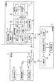
図1に示すように、本発明の第一実施形態による運転支援表示装置10は、自動車である自車両1に搭載されている。運転支援表示装置10は、自車両1の乗員による運転を表示により支援する。具体的に運転支援表示装置10は、図2,3に示すように、自車両1の周辺領域2に存在する周辺対象物3への注意喚起を、自車両1内の乗員に対して表示により実現する。ここで周辺領域2とは、本実施形態では、自車両1よりも前方に広がる設定範囲、例えば40m等の範囲をいう。また、周辺対象物3とは、周辺領域2に移動又は定位することで自車両1の走行を妨げる可能性がある障害物、例えば自転車を含んだ他車両、人工構造物、人間、動物等をいう。
(First embodiment)
As shown in FIG. 1, the driving
図1に示すように運転支援表示装置10は、自車両1の外部において走行状態又は停止状態にある他車両4(図2,3も参照)との間では、車車間通信を行う。具体的に他車両4は、例えば車車間通信可能な自動車等であり、情報取得部4a、周辺検知部4b、情報処理部4c及び送信部4dを備えている。情報取得部4aは、例えばGPSセンサ及び速度センサ等を組み合わせてなり、他車両4の走行情報として走行位置、走行方向及び走行速度を取得する。周辺検知部4bは、例えば超音波センサ、ミリ波レーダ、車載カメラ等からなり、他車両4の周辺領域(図示しない)を検知する。情報処理部4cは、例えばマイクロコンピュータ等からなり、情報取得部4aと周辺検知部4bとに接続されている。情報処理部4cは、自車両1にとっての周辺対象物3となり得る障害物を、周辺検知部4bによる検知結果に基づき特定する。さらに情報処理部4cは、特定した障害物を判別するための障害物情報Ivvを、情報取得部4aによる取得情報及び周辺検知部4bによる検知結果に基づき生成する。ここで障害物情報Ivvには、障害物に関する情報として、種別、存在位置、進行方向及び進行速度が含まれる。送信部4dは、例えば送信アンテナ等からなり、情報処理部4cと接続されている。送信部4dは、車車間通信の規格に従う周波数帯での無線通信により、障害物情報Ivvを他車両4の周辺領域へと送信する。
As shown in FIG. 1, the driving
運転支援表示装置10はまた、自車両1の外部において設置状態にある路側機5(図2,3も参照)との間では、路車間通信を行う。具体的に路側機5は、例えば路車間通信可能なビーコン等の交通インフラ又はモバイル通信用等の基地局であり、受信部5a、周辺検知部5b、情報処理部5c及び送信部5dを備えている。受信部5aは、例えば受信アンテナ等からなり、他車両4又は携帯機器からの送信情報を受信する。周辺検知部5bは、例えば路側カメラ等からなり、路側機5の周辺領域(図示しない)を検知する。情報処理部5cは、例えばマイクロコンピュータ等からなり、受信部5aと周辺検知部5bとに接続されている。情報処理部5cは、自車両1にとっての周辺対象物3となり得る障害物を、受信部5aによる受信情報及び周辺検知部5bによる検知結果に基づき特定する。さらに情報処理部5cは、特定した障害物を判別するための障害物情報Irvを、受信部5aによる受信情報及び周辺検知部5bによる検知結果に基づき生成する。ここで障害物情報Irvには、障害物に関する情報として、種別、存在位置、進行方向及び進行速度が含まれる。送信部5dは、例えば送信アンテナ等からなり、情報処理部5cと接続されている。送信部5dは、路車間通信の規格に従う周波数帯での無線通信により、障害物情報Ivvを路側機5の周辺領域へと送信する。
The driving
運転支援表示装置10は、こうした自車両1の外部要素4,5との間での通信により障害物情報Irv,Ivvを受信して周辺対象物3への注意喚起を行うために、情報取得部20、受信部30、周辺検知部40、情報処理部50及び表示部60を備えている。情報取得部20は、例えばGPSセンサ及び速度センサ等を組み合わせてなり、自車両1の走行状態に関する自車両情報Isとして、走行位置、走行方向及び走行速度を取得する。
The driving
「受信手段」としての受信部30は、例えば受信アンテナ等からなり、自車両1の外部要素4,5からの障害物情報Irv,Ivvを所定のサンプリング周期で受信する。ここで受信部30は、自車両1よりも前方に位置する他車両4との距離が例えば40m等の設定距離以内に接近した場合に、周辺対象物3に関する対象物情報Itとして、障害物情報Irvを受信する。故にこの場合には、対象物情報Itにより特定される周辺対象物3は、障害物情報Irvにより特定される設定距離以内の障害物と一致する。また一方で受信部30は、自車両1よりも前方に位置する路側機5との距離が例えば40m等の設定距離以内に接近した場合に、周辺対象物3に関する対象物情報Itとして、障害物情報Ivvを受信する。故にこの場合には、対象物情報Itにより特定される周辺対象物3は、障害物情報Ivvにより特定される設定距離以内の障害物と一致する。
The receiving
以上より対象物情報Itには、車車間通信により少なくとも一台の他車両4から受信した障害物情報Irvと、路車間通信により少なくとも一つの路側機5から受信した障害物情報Ivvとが、含まれることになる。そこで本実施形態では、サンプリング周期毎に受信部30の受信した障害物情報Irv,Ivvが論理和処理されることで、対象物情報Itが取得されるようになっている。
As described above, the object information It includes the obstacle information Irv received from at least one
「検知手段」としての周辺検知部40は、例えば車載カメラ、超音波センサ、ミリ波レーダ等からなり、自車両1において周辺領域2を検知する。ここで、特に本実施形態の周辺検知部40は、自車両1よりも前方を撮影可能な車載カメラ41を少なくとも有してなり、周辺対象物3の含まれる周辺領域2を当該撮影により検知可能となっている。そこで本実施形態では、車載カメラ41により撮影可能な領域の全域を、周辺対象物3の検知対象とする周辺領域2の全域として定義している。尚、周辺検知部40については、本実施形態では運転支援表示装置10の構成要素として説明しているが、自車両1において運転支援表示装置10以外の構成要素であっても、勿論よい。
The
情報処理部50は、例えばマイクロコンピュータ等からなり、情報取得部20と受信部30と周辺検知部40とに接続されている。情報処理部50は、処理プログラムの実行により機能的に構築される複数のブロック51,52,53,54を、有している。
The
「選定手段」としての選定ブロック51は、対象物情報Itにより特定される少なくとも一つの周辺対象物3の中から、自車両1との衝突が予測される衝突対象物3aを、選定する。具体的に選定ブロック51は、まず、受信部30の受信した対象物情報Itにより、周辺対象物3を特定する。さらに選定ブロック51は、受信部30の受信した対象物情報Itと共に、情報取得部20の取得した自車両情報Isを利用することで、自車両1と周辺対象物3との衝突確率を算出する。その結果、算出した衝突確率が設定確率以上となった場合に選定ブロック51は、当該衝突確率以上の周辺対象物3を衝突対象物3aとして選定する。ここで衝突確率は、処理プログラム上にて実行されるシミュレータにより算出される。このとき、衝突対象物3aの存在位置及び自車両1の走行位置の対比から求められる離間距離と、衝突対象物3aの進行方向及び自車両1の走行方向と、衝突対象物3aの進行速度及び自車両1の走行速度とに基づくことで、衝突確率が算出される。また、衝突対象物3aの選定基準となる設定確率は、自車両1の安全を確保する観点において注意喚起が必要な衝突確率のうち例えば最も安全側の確率等に、適宜設定される。
The
「限定手段」及び「設定手段」としての設定ブロック52は、周辺検知部40により周辺領域2の周辺対象物3として衝突対象物3aを検知するための検知範囲A及び検知パラメータPを、可変設定する。具体的に設定ブロック52は、車載カメラ41により実際に撮影される周辺領域2のうち検知範囲Aとして切り出すことで画像データ化する領域を、衝突対象物3aが存在すると推定される部分領域2a(図2,3を参照)に、限定する。それと共に設定ブロック52は、検知範囲Aである部分領域2aの画像データから衝突対象物3aを認識するための検知感度を、検知パラメータPとして、当該感度の高くなる側へと変化させる。これら検知範囲A及び検知パラメータPの設定は、受信部30の受信した対象物情報Itと、情報取得部20の取得した自車両情報Isとに基づく。このとき、少なくとも衝突対象物3aの存在位置及び自車両1の走行位置が、検知範囲A及び検知パラメータPの設定に利用される。
The setting
こうして設定ブロック52により設定された検知範囲Aは、周辺検知部40へと与えられることで、周辺領域2のうち部分領域2a分だけが画像データ化される。また、設定ブロック52により設定された検知パラメータPは、後に詳述する判定ブロック53へと与えられることで、部分領域2aの画像データに対する衝突対象物3aの検知感度が高められる。
The detection range A thus set by the setting
「判定手段」としての判定ブロック53は、周辺対象物3が周辺領域2において検知されたか否かを、受信部30の受信した対象物情報Itと、情報取得部20の取得した自車両情報Isとに基づき判定する。具体的に判定ブロック53は、選定ブロック51により周辺対象物3の中から選定された衝突対象物3aにつき、当該選定に利用された対象物情報It及び自車両情報Isを、設定ブロック52により限定された部分領域2aの画像データに基づく検知情報と照合させる。このとき、少なくとも衝突対象物3aの存在位置及び自車両1の走行位置と、検知パラメータPとして設定ブロック52により高められた検知感度とが、照合に利用される。そして、こうした照合の結果、対象物情報Itと部分領域2aの検知情報とがマッチングした場合に判定ブロック53は、周辺対象物3としての衝突対象物3aが周辺領域2のうち部分領域2aにおいて検知されたとの肯定判定、即ち当該対象物3aが自車両1から可視状態にあるとの判定を下す。一方、対象物情報Itと部分領域2aの検知情報とがアンマッチングの場合に判定ブロック53は、周辺対象物3としての衝突対象物3aが周辺領域2のうち部分領域2aにおいて検知されなかったとの否定判定、即ち当該対象物3aが自車両1から不可視状態にあるとの判定を下す。
The
指令ブロック54は、判定ブロック53による判定結果に応じた表示指令を、表示部60に与える。具体的に指令ブロック54は、判定ブロック53により肯定判定がなされた場合には、可視状態にある周辺対象物3としての衝突対象物3aが周辺領域2に存在していることを注意喚起するように、注意表示Da(図2参照)を表示部60に指令する。このとき指令ブロック54は、可視状態の衝突対象物3aに関する対象物情報Itを、注意表示Daの指令及び同対象物3aの選定時における自車両情報Isと共に、表示部60へと与える。一方で指令ブロック54は、判定ブロック53により否定判定がなされた場合には、不可視状態にある周辺対象物3としての衝突対象物3aが周辺領域2に存在していることを注意喚起するように、注意表示Daよりも強調された強調表示De(図3参照)を表示部60に指令する。このとき指令ブロック54は、不可視状態の衝突対象物3aに関する対象物情報Itを、強調表示Deの指令及び同対象物3aの選定時における自車両情報Isと共に、表示部60へと与える。
The
「表示手段」としての表示部60は、ヘッドアップディスプレイ(HUD)ユニット61及び画像制御ユニット62を、有している。HUDユニット61は、例えば表示器及び光学系等を組み合わせてなり、表示形成した画像7を自車両1のウインドシールド6(図2,3参照)へと投影する。その結果、ウインドシールド6へ投影された画像7は、注意表示Da又は強調表示Deとなる虚像として、自車両1内の乗員により視認可能に表示される。ここで、「投影部材」としてのウインドシールド6は、自車両1において周辺領域2の実像8を透過するため、自車両1内の乗員には、注意表示又は強調表示された虚像が当該実像8と重畳されて視認されることとなる。また、本実施形態のウインドシールド6における画像7の投影領域6aは、図2,3に破線で示すように、自車両1のうち同シールド6の下部範囲に限定されている。
The
画像制御ユニット62は、HUDユニット61によりウインドシールド6へ投影する画像7のデータを、指令ブロック54からの指令に従って生成する。具体的に画像制御ユニット62は、指令ブロック54から注意表示Daの指令を受けた場合には、対象物情報It及び自車両情報Isを利用することで、図2に示す如き指示画像7aをデータ生成する。このとき指示画像7aは、可視状態にある周辺対象物3としての衝突対象物3aを同画像7aの虚像表示状態にて指示するように、生成される。ここで、特に本実施形態の指示画像7aは、衝突対象物3aの存在位置及び自車両1の走行位置に基づき生成されることで、ウインドシールド6を通して視認される衝突対象物3aの存在方向を、三角形を呈した簡易図形の先端により指示可能となっている。また、本実施形態の指示画像7aは、衝突対象物3aの進行方向及び自車両1の走行方向と、衝突対象物3aの進行速度及び自車両1の走行速度とに基づき生成されることで、図形の向きを適宜変化させて、衝突対象物3aの存在方向を的確に指示可能となっている。このようにしてデータ生成される指示画像7aは、HUDユニット61により表示形成されてウインドシールド6へと投影されることで、衝突対象物3aを対象とした注意表示Daの虚像となる。
The
一方、指令ブロック54から強調表示Deの指令を受けた場合に画像制御ユニット62は、対象物情報It及び自車両情報Isを利用することで、図3に示す如き対象物画像7bをデータ生成する。このとき対象物画像7bは、不可視状態にある周辺対象物3としての衝突対象物3aを具体的に模した図形となるように、生成される。例えば図3は、衝突対象物3aが自転車である場合の対象物画像7bの形状を示しているが、衝突対象物3aが自転車以外であっても、それに応じた形状の対象物画像7bが生成される。ここで、特に本実施形態の対象物画像7bは、衝突対象物3aの存在位置及び自車両1の走行位置に基づき生成されることで、不可視状態にある衝突対象物3aの存在位置に対して投影領域6a内での可及的に近接した箇所に、虚像表示されるようになっている。また、本実施形態の対象物画像7bは、衝突対象物3aの進行方向及び自車両1の走行方向と、衝突対象物3aの進行速度及び自車両1の走行速度とに基づき生成されることで、図形の向きを適宜変化させて、当該対象物3aの進行状況を的確に報知可能となっている。さらに本実施形態では、図3に示す如く対象物画像7bの近傍に虚像表示されることで、不可視状態にある衝突対象物3aの存在方向を指示するように、指示画像7aも併せて生成される。このようにして指示画像7aと共にデータ生成される対象物画像7bは、HUDユニット61により表示形成されてウインドシールド6へと投影されることで、衝突対象物3aを対象として注意表示Daとは異なる態様にて強調された強調表示Deの虚像となる。
On the other hand, when receiving the instruction of the highlight display De from the
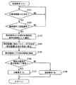
さて、ここまで説明した運転支援表示装置10による支援表示フローを、図4に基づき以下に説明する。本支援表示フローは、自車両1のエンジンスイッチがオンされるのに応じて開始され、同エンジンスイッチがオフされるのに応じて終了する。
Now, a support display flow by the driving
具体的に支援表示フローのS101では、自車両1の外部要素4,5からの障害物情報Irv,Ivvを対象物情報Itとして受信したか否かを、受信部30により判定する。その結果、否定判定がなされる間は、S101を繰り返す一方、肯定判定がなされると、S102へ移行する。
Specifically, in S101 of the support display flow, the receiving
S102では、S101において受信した対象物情報Itにより特定される周辺対象物3の衝突確率が設定確率以上であるか否かを、選定ブロック51により判定する。その結果、否定判定がなされる間は、S101へ戻る一方、肯定判定がなされると、S103へ移行する。
In S102, the
S103では、衝突確率が設定確率以上の周辺対象物3を衝突対象物3aとして、選定ブロック51により選定する。また続くS104では、周辺対象物3として衝突対象物3aを検知するための検知範囲A及び検知パラメータPを、設定ブロック52により設定する。
In S103, the
さらに続くS105では、S104において設定された検知範囲Aに従って、周辺領域2のうち部分領域2aを周辺検知部40により検知して画像データ化する。またさらに続くS106では、周辺対象物3としての衝突対象物3aが周辺領域2の部分領域2aにおいて検知されたか否かを、S104において設定された検知パラメータPに従って、判定ブロック53により判定する。
In subsequent S105, the
S106により肯定判定がなされた場合には、S107へ移行する。S107では、S106により肯定判定がなされた周辺対象物3としての衝突対象物3aの存在を、指令ブロック54から表示部60への指令に従った注意表示Daにより、注意喚起する。一方、S106により否定判定がなされた場合には、S108へ移行する。S108では、S106により否定判定がなされた周辺対象物3としての衝突対象物3aの存在を、指令ブロック54から表示部60への指令に従った強調表示Deにより、注意喚起する。そして、これらS107,S108のいずれの実行終了後にも、S101へと戻ることになる。
If an affirmative determination is made in S106, the process proceeds to S107. In S107, the presence of the collision target object 3a as the peripheral target object 3 for which an affirmative determination is made in S106 is alerted by a caution display Da according to a command from the
(作用効果)
以上説明した第一実施形態の作用効果を、以下に説明する。
(Function and effect)
The effects of the first embodiment described above will be described below.
第一実施形態によると、自車両1の外部から受信した対象物情報Itにより特定される周辺対象物3が周辺領域2において検知されなかった場合には、周辺対象物3が不可視状態にあるとして、その存在が強調表示され得る。これによれば、周辺対象物3を不可視状態にする死角形成物9(図3参照)については、存在の認識も種別の認識も不要にしながら、当該不可視状態にある周辺対象物3については、外部からの対象物情報Itに基づき特定して強調表示Deによる注意喚起を実現できる。したがって、高いロバスト性を達成することが可能となる。
According to the first embodiment, when the surrounding object 3 specified by the object information It received from the outside of the
また、第一実施形態によると、受信した対象物情報Itにより特定される周辺対象物3の中から、強調表示Deの対象として選定される周辺対象物3は、自車両1との衝突が予測される衝突対象物3aに絞られる。これによれば、ロバスト性が高くなった分、不可視状態であっても衝突の可能性は低い周辺対象物3までもが強調表示されることで、自車両1内の乗員が煩わしさを感じるようなことにつき、抑制が可能となる。
Further, according to the first embodiment, the peripheral object 3 selected as the target of the highlighting De among the peripheral objects 3 specified by the received object information It is predicted to collide with the
さらに、第一実施形態によると、周辺領域2のうち周辺対象物3の検知有無が判定される領域は、対象物情報Itに基づくことで、周辺対象物3の存在が推定される部分領域2aに限定されるので、周辺対象物3の検知から判定までに要する時間を短縮できる。これによれば、不可視状態の周辺対象物3を早期に特定して、リアルタイムな強調表示Deにより注意喚起することが可能となる。
Furthermore, according to the first embodiment, the area in which the presence or absence of the detection of the peripheral object 3 in the
またさらに、第一実施形態によると、周辺対象物3を検知するために設定される検知パラメータPは、受信した対象物情報Itに基づき検知感度の高くなる側へと変化するので、不可視状態の周辺対象物3が確実に検知され得る。これによれば、不可視状態の周辺対象物3を検知できないことによるロバスト性の低下につき、抑制することが可能となる。 Still further, according to the first embodiment, the detection parameter P set for detecting the peripheral object 3 changes to a higher detection sensitivity based on the received object information It. The peripheral object 3 can be reliably detected. According to this, it becomes possible to suppress a decrease in robustness due to the inability to detect the peripheral object 3 in an invisible state.
加えて、第一実施形態によると、車車間通信及び路車間通信のそれぞれにより自車両1の外部要素4,5から受信した障害物情報Ivv,Irvを含む対象物情報Itに基づき、周辺対象物3の検知有無が判定される。これによれば、周辺対象物3を不可視状態にする死角の形成物は認識できなくても、当該不可視状態の周辺対象物3については、自車両1の外部要素4,5との通信を利用して正確に特定できる。故に、高いロバスト性も相俟って、不可視状態の周辺対象物3に対する強調表示Deの精度を、向上させることが可能となる。
In addition, according to the first embodiment, the peripheral object is based on the object information It including the obstacle information Ivv and Irv received from the
また加えて、第一実施形態によると、受信した対象物情報Itにより特定される周辺対象物3につき、検知された場合には可視状態としての存在が注意表示され得る一方、検知されなかった場合には不可視状態としての存在が強調表示され得る。これによれば、注意喚起の重要度が増す不可視状態の周辺対象物3に対しては、可視状態の周辺対象物3に対する注意表示Daとは異なる態様にて強調表示が行われることで、当該強調表示Deの認識性を高めることが可能となる。しかも、可視状態の周辺対象物3に対する注意表示Daが不可視状態の周辺対象物3に対して誤って行われることを、高いロバスト性により抑制することも可能となる。 In addition, according to the first embodiment, when the peripheral object 3 specified by the received object information It is detected, the presence as a visible state can be displayed with caution when it is detected, but it is not detected. The presence of an invisible state can be highlighted. According to this, for the invisible peripheral object 3 in which the importance of alerting is increased, highlighting is performed in a manner different from the caution display Da for the peripheral object 3 in the visible state. The recognizability of the highlight display De can be improved. In addition, it is possible to suppress the warning display Da for the peripheral object 3 in the visible state from being erroneously performed on the peripheral object 3 in the invisible state by high robustness.
さらに加えて、第一実施形態によると、自車両1において周辺領域2の実像8を透過するウインドシールド6へ画像7が投影されることで、注意表示Da又は強調表示Deとしての虚像表示が行われる。ここで注意表示Daは、周辺対象物3を指示する指示画像7aの虚像表示により、実現される。故に、周辺対象物3の指示に特化した比較的簡素な指示画像7aが虚像表示されることによれば、可視状態の周辺対象物3に対する注意表示Daに起因して自車両1内の乗員が煩わしさを感じることにつき、抑制が可能となる。また、一方で強調表示Deは、少なくとも周辺対象物3を模した対象物画像7bの虚像表示により、実現される。故に、不可視状態の周辺対象物3を模すことで具体的なイメージを与え得る対象物画像7bが虚像表示されることによれば、強調表示Deの認識性を高めることが可能となる。
In addition, according to the first embodiment, the image 7 is projected onto the
(第二実施形態)
図5に示すように本発明の第二実施形態は、第一実施形態の変形例である。第二実施形態による情報処理部2050は、設定ブロック52に代わる機能ブロックとして、限定ブロック2052を有している。
(Second embodiment)
As shown in FIG. 5, the second embodiment of the present invention is a modification of the first embodiment. The
「限定手段」及び「判定手段」としての限定ブロック2052は、検知パラメータPについては第一実施形態と同様に可変設定する一方、画像データ化する検知範囲Aについては周辺領域2の全域に固定設定する。それと共に限定ブロック2052は、画像データ化された周辺領域2全域のうち、周辺対象物3である衝突対象物3aの検知有無が判定ブロック2053により判定される領域を、限定する。具体的に限定ブロック2052は、周辺領域2のうち衝突対象物3aが存在すると推定される部分領域2aを、判定ブロック2053による判定対象領域Jとして限定する。こうした判定対象領域Jとしての部分領域2aの限定は、受信部30の受信した対象物情報Itと、情報取得部20の取得した自車両情報Isとに基づく。このとき、少なくとも衝突対象物3a及び自車両1の走行位置の存在位置が、部分領域2aの限定に利用される。
The limiting
こうして限定ブロック2052により設定された検知範囲Aは、周辺検知部40へと与えられることで、周辺領域2全域が画像データ化される。また、限定ブロック2052により設定された検知パラメータP及び判定対象領域Jは、後に詳述する判定ブロック2053へと与えられることで、当該領域Jとなる部分領域2aの画像データに対する衝突対象物3aの検知感度が高められる。
Thus, the detection range A set by the limiting
このような限定ブロック2052を有する情報処理部2050において、「判定手段」としての判定ブロック2053は、第一実施形態に準じて対象物情報It及び自車両情報Isと照合させる情報を、周辺領域2全域の画像データのうち、限定ブロック2052により限定された部分領域2aの画像データに基づく検知情報とする。それ以外の点について判定ブロック2053は、第一実施形態の判定ブロック53と同様に機能する。
In the
さて、ここまで説明の如き情報処理部2050を備えた運転支援表示装置2010は、図6に示すように、S104,S105がそれぞれS2104,S2105に変更された支援表示フローを、実行する。具体的にS2104では、限定ブロック2052により、検知範囲A及び検知パラメータPを設定すると共に、判定ブロック2053での判定対象領域Jを周辺領域2の部分領域2aに限定する。さらにS2105では、S2104において設定された検知範囲Aに従って、周辺領域2の全域を周辺検知部40により検知して画像データ化する。これらの以外の点についは、第一実施形態と同様に支援表示フローが実行される。
Now, as shown in FIG. 6, the driving
以上説明した第二実施形態によると、第一実施形態と同様の作用効果を発揮することが可能となる。 According to the second embodiment described above, the same operational effects as those of the first embodiment can be exhibited.
(第三実施形態)
図7に示すように本発明の第三実施形態は、第一実施形態の変形例である。第三実施形態では、一台の他車両4からの障害物情報Ivvのみが対象物情報Itとして受信部30により受信されている状況につき、想定される。かかる想定状況下では、他車両4が自車両1の周辺領域2から離れたことで、当該周辺領域2には周辺対象物3が存在しているにも拘らず、対象物情報Itとなる障害物情報Ivvが他車両4から途絶えてしまう懸念がある。
(Third embodiment)
As shown in FIG. 7, the third embodiment of the present invention is a modification of the first embodiment. In the third embodiment, it is assumed that only the obstacle information Ivv from one
そこで、第三実施形態による情報処理部3050では、追加の機能ブロックとして、保持ブロック3055を有している。保持ブロック3055は、対象物情報Itとして唯一受信していた障害物情報Ivvが他車両4から途絶えた場合に、当該途絶直前のサンプリング周期に対象物情報Itとして受信していた障害物情報Ivvを、今度は保持情報Ithとして保持する。ここで保持情報Ithの保持機能は、衝突対象物3aが選定される間に限って、継続される。そして、こうした保持情報Ithの保持状態下、選定ブロック51による衝突対象物3aの選定、設定ブロック52による検知範囲A及び検知パラメータPの設定、並びに判定ブロック53による周辺対象物3の検知有無の判定は、当該保持情報Ithに基づくこととなる。
Therefore, the
また、保持情報Ithの保持状態下、保持ブロック3055から表示部3060には、指令ブロック54を通じて当該保持情報Ithが与えられる。そこで、第三実施形態による「表示手段」としての表示部3060では、かかる保持情報Ithと共に強調表示Deの指令を受けた場合の画像制御ユニット3062により、強調表示Deとなる対象物画像7b及び指示画像7aの虚像表示が変化させられる。このときには例えば、対象物画像7b及び指示画像7aの虚像表示を、第一実施形態と同様な実線表示(図3参照)から、図8に示す如き破線表示に変化させてもよい。あるいは図示はしないが、対象物画像7b及び指示画像7aの虚像表示を、点滅表示させてもよい。
Further, the holding information Ith is given from the holding
さて、ここまで説明の如き情報処理部3050及び表示部3060を備えた運転支援表示装置3010では、支援表示フローと並列して、図9に示す如きロスト表示フローが実行される。本ロスト表示フローも、自車両1のエンジンスイッチがオンされるのに応じて開始され、同エンジンスイッチがオフされるのに応じて終了する。
Now, in the driving
具体的にロスト表示フローのS3100では、直前のサンプリング周期に唯一受信していた対象物情報Itとしての障害物情報Ivvが途絶えたか否かを、受信部30により判定する。その結果、否定判定がなされる間は、S3100を繰り返す一方、肯定判定がなされると、S3101へ移行する。
Specifically, in S3100 of the lost display flow, the receiving
S3101では、途絶前に受信していた障害物情報Ivvを保持情報Ithとして、保持ブロック3055により保持する。また続くS3102では、S3101において保持した保持情報Ithにより特定される周辺対象物3の衝突確率が設定確率以上であるか否かを、選定ブロック51により判定する。その結果、否定判定がなされると、S3100へ戻る一方、肯定判定がなされると、S103へ移行する。ここで、S3100へと戻るときは、受信部30でのサンプリング周期が切り替わっていることで、当該S3100の実行直前には、障害物情報Ivvが非受信状態となっている。そのため、S3101には移行することなく、保持情報Ithの保持状態が終了することになる。また一方で、S103及びそれに後続するS104〜S107については、支援表示フローの場合に準じたものとなるので、説明を省略する。但し、S106により否定判定がなされた場合には、S3108へと移行する。
In step S3101, the obstacle information Ivv received before the interruption is held as holding information Ith by the holding
S3108では、S106により否定判定がなされた周辺対象物3としての衝突対象物3aの存在を、指令ブロック54から表示部60への指令に従って支援表示フローの場合とは変化させた強調表示Deにより、注意喚起する。尚、S3108の実行終了後並びに説明省略のS107の実行終了後には、S3100へと戻ることになる。
In S3108, the highlighted display De is used to change the presence of the collision target object 3a as the peripheral target object 3 determined to be negative in S106 from the case of the support display flow according to the command from the
以上説明した第三実施形態によると、他車両4からの対象物情報Itが途絶えた場合には、当該途絶前に受信していた対象物情報Itとしての保持情報Ithに基づき、周辺対象物3の検知有無が判定される。これによれば、車車間通信相手の他車両4が周辺領域2から離れることに起因してロバスト性が低下することにつき、抑制が可能となる。尚、このような第三実施形態に準じて第二実施形態を変形させることも、勿論可能である。
According to the third embodiment described above, when the object information It from the
(他の実施形態)
以上、本発明の複数の実施形態について説明したが、本発明は、それらの実施形態に限定して解釈されるものではなく、本発明の要旨を逸脱しない範囲内において種々の実施形態及び組み合わせに適用することができる。
(Other embodiments)
Although a plurality of embodiments of the present invention have been described above, the present invention is not construed as being limited to these embodiments, and various embodiments and combinations can be made without departing from the scope of the present invention. Can be applied.
具体的に、第一及び第二実施形態に関する変形例1では、選定ブロック51による衝突対象物3aの選定機能を、実現しなくてもよい。ここで、かかる変形例1の場合に他ブロック52,53,54,2052,2053及び画像制御ユニット62による各機能は、衝突対象物3aを周辺対象物3の全てと読み替えることで、実現可能となる。
Specifically, in the first modification regarding the first and second embodiments, the selection function of the collision object 3a by the
第一及び第三実施形態に関する変形例2では、設定ブロック52による検知範囲Aの設定として、周辺領域2に対して行われる部分領域2aの限定機能を、実現しなくてもよい。また、第二実施形態に関する変形例3では、限定ブロック2052による判定対象領域Jとしての部分領域2aの限定機能を、実現しなくてもよい。ここで、これら変形例2,3の場合に判定ブロック53,2053による判定機能は、部分領域2aを周辺領域2の全域と読み替えることで、実現可能となる。また、変形例2の場合には、周辺検知部40として車載カメラ41を有している必要性はなく、例えば超音波センサ又はミリ波レーダ等といった車載カメラ41以外の手段により周辺領域2を検知する周辺検知部40を、採用してもよい。
In the second modification regarding the first and third embodiments, as a setting of the detection range A by the setting
第一〜第三実施形態に関する変形例4では、設定ブロック52又は限定ブロック2052により検知パラメータPを、検知感度とは異なる要因により可変設定してもよい。また、第一〜第三実施形態に関する変形例5では、設定ブロック52又は限定ブロック2052により検知パラメータPを、設定しない又は固定設定してもよい。
In the
第一〜第三実施形態に関する変形例6では、自車両情報Iss及び対象物情報Itに基づき予測される衝突までの時間等を考慮して、周辺領域2として扱う範囲を可変設定してもよい。ここで、かかる変形例6の場合には、対象物情報Itとしての障害物情報Irv,Ivvの受信可能距離についても、周辺領域2と同様に可変設定してもよい。
In the sixth modification related to the first to third embodiments, the range to be treated as the
第一〜第三実施形態に関する変形例7では、車車間通信による障害物情報Ivv及び路車間通信による障害物情報Irvのうち一方を、対象物情報Itとして受信しなくてもよい。また、第一〜第三実施形態に関する変形例8では、車車間通信による障害物情報Ivv及び路車間通信による障害物情報Irvの少なくとも一方に加えて又は代えて、対象物情報Itとなり得る障害物情報を、例えば衛星通信等により受信してもよい。
In the modified example 7 regarding the first to third embodiments, one of the obstacle information Ivv by the inter-vehicle communication and the obstacle information Irv by the road-to-vehicle communication may not be received as the object information It. Moreover, in the
第一〜第三実施形態に関する変形例9では、図10,11に破線で示すように、ウインドシールド6における画像7の投影領域6aを、同シールド6の下部から上方に広がる範囲に拡大してもよい。ここで、かかる変形例9の場合に指示画像7aは、衝突対象物3aの存在位置及び自車両1の走行位置に基づき生成されることで、図10に示すように、衝突対象物3aの存在位置を直接的に指示してもよい。また、変形例9の場合に対象物画像7bは、衝突対象物3aの存在位置及び自車両1の走行位置に基づき生成されることで、図11に示すように、衝突対象物3aの存在位置にある死角形成物9に重畳させて虚像表示してもよい。
In the modified example 9 related to the first to third embodiments, as shown by broken lines in FIGS. 10 and 11, the
尚、図11に示す変形例9の強調表示Deでは、対象物画像7bのみが虚像表示されているが、第一〜第三実施形態に準じて対象物画像7bを指示画像7aと併せて表示してもよい。また、第一〜第三実施形態に関する変形例10の強調表示Deでは、変形例9に準じて対象物画像7bのみを虚像表示してもよい。
Note that in the highlight display De of the
第一〜第三実施形態に関する変形例11では、強調表示Deとは異なる態様の注意表示Daとして、強調表示Deよりも簡易的な表現により周辺対象物3(衝突対象物3a)の存在を乗員が直感的に認識可能であれば、三角形以外の図形により指示機能を果たす画像や、指示機能とは異なる機能を果たす画像等を採用してもよい。また、第一〜第三実施形態に関する変形例12では、判定ブロック53,2053により肯定判定がなされた場合に、指令ブロック54及び画像制御ユニット62,3062の協働による注意表示Daを、実現しなくてもよい。
In the modification 11 regarding the first to third embodiments, the presence of the peripheral object 3 (collision object 3a) is expressed by a simpler expression than the highlight display De as the attention display Da having a different form from the highlight display De. Can be recognized intuitively, an image that performs an instruction function using a figure other than a triangle, an image that performs a function different from the instruction function, or the like may be employed. In the twelfth modified example related to the first to third embodiments, when an affirmative determination is made by the determination blocks 53 and 2053, the attention display Da by the cooperation of the
第一〜第三実施形態に関する変形例13では、情報処理部50,2050,3050の各ブロック51,52,53,54,2052,2053,3055の少なくとも一つを、処理プログラムの実行により機能的に構築する代わりに、電気回路により物理的に構築してもよい。また、第一〜第三実施形態に関する変形例14では、HUDユニット61により画像7を虚像表示する表示部60,3060以外にも、例えば液晶パネル等の表示パネルにより画像7を実像表示する表示部60,3060を、採用してもよい。
In the modification 13 regarding the first to third embodiments, at least one of the
1 自車両、2 周辺領域、2a 部分領域、3 周辺対象物、3a 衝突対象物、4 他車両、5 路側機、6 ウインドシールド、7 画像、7a 指示画像、7b 対象物画像、8 実像、10,2010,3010 運転支援表示装置、20 情報取得部、30 受信部、40 周辺検知部、41 車載カメラ、50,2050,3050 情報処理部、51 選定ブロック、52 設定ブロック、53,2053 判定ブロック、53 判定ブロック、54 指令ブロック、60,3060 表示部、61 ヘッドアップディスプレイ(HUD)ユニット、62,3062 画像制御ユニット、2052 限定ブロック、3055 保持ブロック、A 検知範囲、Da 注意表示、De 強調表示、Irv,Ivv 障害物情報、It 対象物情報、J 判定対象領域、P 検知パラメータ 1 self-vehicle, 2 peripheral area, 2a partial area, 3 peripheral object, 3a collision object, 4 other vehicle, 5 roadside machine, 6 windshield, 7 images, 7a instruction image, 7b object image, 8 real image, 10 , 2010, 3010 Driving support display device, 20 information acquisition unit, 30 reception unit, 40 surrounding detection unit, 41 on-vehicle camera, 50, 2050, 3050 information processing unit, 51 selection block, 52 setting block, 53, 2053 determination block, 53 judgment block, 54 command block, 60, 3060 display unit, 61 head-up display (HUD) unit, 62, 3062 image control unit, 2052 limited block, 3055 holding block, A detection range, Da caution display, De highlight display, Irv, Ivv Obstacle information, It object information, J Constant region of interest, P sensed parameters
Claims (7)
前記自車両の前記周辺領域に存在する周辺対象物(3,3a)に関して、対象物情報(It,Ivv,Irv)を前記自車両の外部から受信する受信手段(30)と、
前記受信手段の受信した前記対象物情報により特定される前記周辺対象物が前記検知手段により検知されたか否かを、判定する判定手段(53,2053)と、
前記判定手段により否定判定がなされた場合に、当該否定判定がなされた前記周辺対象物の存在を強調表示する表示手段(60,3060)と、
前記周辺領域のうち前記周辺対象物が存在すると推定される部分領域(2a)を、前記受信手段の受信した前記対象物情報に基づき限定する限定手段(52,2052)とを、備え、
前記判定手段は、前記部分領域において前記周辺対象物が検知されたか否かを、判定することを特徴とする運転支援表示装置。 A driving support display device (10, 2010, 3010) for supporting the driving of the host vehicle by display based on the result of detecting the surrounding area (2) by the detecting means (40) in the host vehicle (1),
Receiving means (30) for receiving object information (It, Ivv, Irv) from the outside of the own vehicle regarding the surrounding objects (3, 3a) existing in the peripheral area of the own vehicle;
A determination means (53, 2053) for determining whether or not the surrounding object specified by the object information received by the reception means has been detected by the detection means;
Display means (60, 3060) for highlighting the presence of the surrounding object for which the negative determination is made when a negative determination is made by the determination means ;
Limiting means (52, 2052) for limiting the partial area (2a) in which the surrounding object is estimated to be present in the surrounding area based on the object information received by the receiving means,
The determination means determines whether or not the surrounding object has been detected in the partial area .
前記判定手段は、前記他車両からの前記対象物情報が途絶えた場合に、当該途絶前において前記受信手段の受信していた前記対象物情報に基づき、前記検知手段による前記周辺対象物の検知有無を判定することを特徴とする請求項4に記載の運転支援表示装置。 The object information includes at least information (Ivv) received by the receiving unit from another vehicle outside the host vehicle through the inter-vehicle communication,
In the case where the object information from the other vehicle is interrupted, the determination means determines whether the surrounding object is detected by the detection means based on the object information received by the receiving means before the interruption. The driving support display device according to claim 4 , wherein:
前記周辺対象物を指示する指示画像(7a)の前記虚像により注意表示する一方、前記周辺対象物を模した対象物画像(7b)の前記虚像により強調表示することを特徴とする請求項6に記載の運転支援表示装置。 The display means for displaying a virtual image of the image by projecting the image (7, 7a, 7b) onto a projection member that transmits the real image of the peripheral area in the host vehicle,
While note displayed by the virtual image of the instruction image (7a) for instructing the peripheral object, in claim 6, characterized in that the highlighted by the virtual image of the object image simulating the peripheral object (7b) The driving assistance display device described.
Priority Applications (2)
| Application Number | Priority Date | Filing Date | Title |
|---|---|---|---|
| JP2014104087A JP6028766B2 (en) | 2014-05-20 | 2014-05-20 | Driving support display device |
| US14/714,509 US9785845B2 (en) | 2014-05-20 | 2015-05-18 | Drive support display device |
Applications Claiming Priority (1)
| Application Number | Priority Date | Filing Date | Title |
|---|---|---|---|
| JP2014104087A JP6028766B2 (en) | 2014-05-20 | 2014-05-20 | Driving support display device |
Publications (2)
| Publication Number | Publication Date |
|---|---|
| JP2015219803A JP2015219803A (en) | 2015-12-07 |
| JP6028766B2 true JP6028766B2 (en) | 2016-11-16 |
Family
ID=54556285
Family Applications (1)
| Application Number | Title | Priority Date | Filing Date |
|---|---|---|---|
| JP2014104087A Expired - Fee Related JP6028766B2 (en) | 2014-05-20 | 2014-05-20 | Driving support display device |
Country Status (2)
| Country | Link |
|---|---|
| US (1) | US9785845B2 (en) |
| JP (1) | JP6028766B2 (en) |
Families Citing this family (15)
| Publication number | Priority date | Publication date | Assignee | Title |
|---|---|---|---|---|
| JP6383376B2 (en) * | 2016-03-31 | 2018-08-29 | 株式会社Subaru | Peripheral risk display device |
| WO2017192358A1 (en) | 2016-05-06 | 2017-11-09 | Pcms Holdings, Inc. | Method and system for collaborative sensing for updating dynamic map layers |
| JP6353881B2 (en) * | 2016-08-25 | 2018-07-04 | 株式会社Subaru | Vehicle display device |
| KR102436962B1 (en) | 2017-09-19 | 2022-08-29 | 삼성전자주식회사 | An electronic device and Method for controlling the electronic device thereof |
| JP6687169B2 (en) * | 2018-02-13 | 2020-04-22 | 住友電気工業株式会社 | Information generating device, information generating method, computer program, and wireless communication system |
| JP7102797B2 (en) * | 2018-03-12 | 2022-07-20 | 株式会社リコー | Optical devices, distance measuring devices using them, and moving objects |
| FR3091949B1 (en) * | 2019-01-17 | 2022-03-04 | Transdev Group | Platform and method for supervising an infrastructure for transport vehicles, vehicle, transport system and associated computer program |
| CN109801508B (en) * | 2019-02-26 | 2021-06-04 | 百度在线网络技术(北京)有限公司 | Method and device for predicting movement track of obstacle at intersection |
| JP2020175795A (en) * | 2019-04-19 | 2020-10-29 | マツダ株式会社 | Vehicle control device |
| KR20200130774A (en) * | 2019-05-03 | 2020-11-20 | 삼성전자주식회사 | Electronic apparatus and method for assisting driving of a vehicle |
| WO2020241273A1 (en) * | 2019-05-31 | 2020-12-03 | 住友電気工業株式会社 | Vehicular communication system, onboard device, control method, and computer program |
| JP2021189932A (en) * | 2020-06-03 | 2021-12-13 | トヨタ自動車株式会社 | Moving object detection system |
| CN112061027B (en) * | 2020-07-30 | 2022-03-11 | 南京英锐创电子科技有限公司 | Vehicle-mounted alarm system, vehicle-mounted alarm method and computer equipment |
| JP2022051150A (en) * | 2020-09-18 | 2022-03-31 | 株式会社日立製作所 | Traffic control system and traffic control method |
| GB2605201A (en) * | 2021-03-26 | 2022-09-28 | Nigel Warren Thomas | Road user protection system |
Family Cites Families (15)
| Publication number | Priority date | Publication date | Assignee | Title |
|---|---|---|---|---|
| JP2003291688A (en) * | 2002-04-03 | 2003-10-15 | Denso Corp | Display method, driving support device and program |
| JP4055586B2 (en) * | 2003-01-24 | 2008-03-05 | トヨタ自動車株式会社 | Vehicle driving assistance device |
| JP4585355B2 (en) * | 2005-03-31 | 2010-11-24 | 本田技研工業株式会社 | Inter-vehicle communication system |
| JP4306675B2 (en) * | 2005-12-15 | 2009-08-05 | トヨタ自動車株式会社 | VEHICLE DRIVE SUPPORT DEVICE AND VEHICLE CONTROL DEVICE |
| JP2008059178A (en) | 2006-08-30 | 2008-03-13 | Nippon Soken Inc | Operation support device and program |
| JP2009223845A (en) | 2008-03-19 | 2009-10-01 | Hitachi Ltd | In-vehicle communication equipment |
| JP2010030427A (en) * | 2008-07-29 | 2010-02-12 | Toyota Motor Corp | Parking support system and parking support device |
| JP5017242B2 (en) * | 2008-12-03 | 2012-09-05 | 本田技研工業株式会社 | Visual support device |
| JP2011087006A (en) | 2009-10-13 | 2011-04-28 | Denso Corp | Display device for vehicle |
| JP2011118482A (en) * | 2009-11-30 | 2011-06-16 | Fujitsu Ten Ltd | In-vehicle device and recognition support system |
| JP2011227657A (en) | 2010-04-19 | 2011-11-10 | Honda Motor Co Ltd | Device for monitoring periphery of vehicle |
| DE102010040803A1 (en) * | 2010-09-15 | 2012-03-15 | Continental Teves Ag & Co. Ohg | Visual driver information and warning system for a driver of a motor vehicle |
| JP5691814B2 (en) * | 2011-05-11 | 2015-04-01 | スズキ株式会社 | Driving assistance device |
| US8907814B2 (en) * | 2011-12-19 | 2014-12-09 | Fujitsu Limited | Cooperative vehicle collision warning system |
| DE102012003776B3 (en) * | 2012-02-25 | 2013-07-25 | Volkswagen Ag | Method for identifying a vehicle in a vehicle-to-vehicle communication |
-
2014
- 2014-05-20 JP JP2014104087A patent/JP6028766B2/en not_active Expired - Fee Related
-
2015
- 2015-05-18 US US14/714,509 patent/US9785845B2/en active Active
Also Published As
| Publication number | Publication date |
|---|---|
| JP2015219803A (en) | 2015-12-07 |
| US20150339534A1 (en) | 2015-11-26 |
| US9785845B2 (en) | 2017-10-10 |
Similar Documents
| Publication | Publication Date | Title |
|---|---|---|
| JP6028766B2 (en) | Driving support display device | |
| CN110831819B (en) | Parking assist method and parking assist device | |
| JP6372402B2 (en) | Image generation device | |
| JP4807263B2 (en) | Vehicle display device | |
| EP3217377A1 (en) | Vehicle lighting system | |
| JP5338801B2 (en) | In-vehicle obstacle information notification device | |
| EP2487906B1 (en) | Control device and vehicle surrounding monitoring device | |
| JP5712119B2 (en) | Pedestrian notification device for vehicles | |
| JP6451101B2 (en) | Vehicle communication device | |
| JP6620527B2 (en) | Information processing apparatus and in-vehicle system | |
| JP6665605B2 (en) | Display control device and display control method | |
| JPWO2009072366A1 (en) | Vehicle information display device | |
| JP2011118483A (en) | On-vehicle device and recognition support system | |
| JP2008280026A (en) | Driving assistance device | |
| JP2006227811A (en) | Driving support apparatus | |
| JP2010173619A (en) | Head-up display device | |
| JP2015011457A (en) | Vehicle information provision device | |
| CN111937055A (en) | Driving support device | |
| JP2017111498A (en) | Driving support device | |
| JP2016146170A (en) | Image generation device and image generation method | |
| US20200231097A1 (en) | Display system, vehicle control apparatus, display control method, and storage medium for storing program | |
| JP2007025739A (en) | Image display device for vehicle | |
| JP2020095044A (en) | Display controller and display control method | |
| JP5166975B2 (en) | Vehicle periphery monitoring device and vehicle periphery monitoring method | |
| JP2012069154A (en) | Obstacle monitoring device |
Legal Events
| Date | Code | Title | Description |
|---|---|---|---|
| A621 | Written request for application examination |
Free format text: JAPANESE INTERMEDIATE CODE: A621 Effective date: 20151028 |
|
| A977 | Report on retrieval |
Free format text: JAPANESE INTERMEDIATE CODE: A971007 Effective date: 20160711 |
|
| A131 | Notification of reasons for refusal |
Free format text: JAPANESE INTERMEDIATE CODE: A131 Effective date: 20160719 |
|
| A521 | Request for written amendment filed |
Free format text: JAPANESE INTERMEDIATE CODE: A523 Effective date: 20160831 |
|
| TRDD | Decision of grant or rejection written | ||
| A01 | Written decision to grant a patent or to grant a registration (utility model) |
Free format text: JAPANESE INTERMEDIATE CODE: A01 Effective date: 20160920 |
|
| A61 | First payment of annual fees (during grant procedure) |
Free format text: JAPANESE INTERMEDIATE CODE: A61 Effective date: 20161003 |
|
| R151 | Written notification of patent or utility model registration |
Ref document number: 6028766 Country of ref document: JP Free format text: JAPANESE INTERMEDIATE CODE: R151 |
|
| R250 | Receipt of annual fees |
Free format text: JAPANESE INTERMEDIATE CODE: R250 |
|
| R250 | Receipt of annual fees |
Free format text: JAPANESE INTERMEDIATE CODE: R250 |
|
| R250 | Receipt of annual fees |
Free format text: JAPANESE INTERMEDIATE CODE: R250 |
|
| LAPS | Cancellation because of no payment of annual fees |