JP6684355B2 - A vehicle door assembly having an insertion area in a frame-side guide member, which is used for constructing an embedded glass, and a method of mounting the same - Google Patents
A vehicle door assembly having an insertion area in a frame-side guide member, which is used for constructing an embedded glass, and a method of mounting the same Download PDFInfo
- Publication number
- JP6684355B2 JP6684355B2 JP2018536864A JP2018536864A JP6684355B2 JP 6684355 B2 JP6684355 B2 JP 6684355B2 JP 2018536864 A JP2018536864 A JP 2018536864A JP 2018536864 A JP2018536864 A JP 2018536864A JP 6684355 B2 JP6684355 B2 JP 6684355B2
- Authority
- JP
- Japan
- Prior art keywords
- frame
- vehicle door
- glass
- side guide
- window
- Prior art date
- Legal status (The legal status is an assumption and is not a legal conclusion. Google has not performed a legal analysis and makes no representation as to the accuracy of the status listed.)
- Expired - Fee Related
Links
- 239000011521 glass Substances 0.000 title claims description 137
- 238000003780 insertion Methods 0.000 title claims description 51
- 230000037431 insertion Effects 0.000 title claims description 51
- 238000000034 method Methods 0.000 title claims description 23
- 239000005357 flat glass Substances 0.000 claims description 160
- 239000000463 material Substances 0.000 description 9
- 238000007789 sealing Methods 0.000 description 9
- 238000000465 moulding Methods 0.000 description 8
- 238000010276 construction Methods 0.000 description 6
- 239000000243 solution Substances 0.000 description 6
- 239000002184 metal Substances 0.000 description 4
- 239000004033 plastic Substances 0.000 description 4
- 241001074085 Scophthalmus aquosus Species 0.000 description 2
- 230000000712 assembly Effects 0.000 description 2
- 238000000429 assembly Methods 0.000 description 2
- 238000002347 injection Methods 0.000 description 2
- 239000007924 injection Substances 0.000 description 2
- 238000012986 modification Methods 0.000 description 2
- 230000004048 modification Effects 0.000 description 2
- 230000007704 transition Effects 0.000 description 2
- 238000004026 adhesive bonding Methods 0.000 description 1
- 230000002093 peripheral effect Effects 0.000 description 1
- 230000000717 retained effect Effects 0.000 description 1
Images


Classifications
-
- B—PERFORMING OPERATIONS; TRANSPORTING
- B60—VEHICLES IN GENERAL
- B60J—WINDOWS, WINDSCREENS, NON-FIXED ROOFS, DOORS, OR SIMILAR DEVICES FOR VEHICLES; REMOVABLE EXTERNAL PROTECTIVE COVERINGS SPECIALLY ADAPTED FOR VEHICLES
- B60J5/00—Doors
- B60J5/04—Doors arranged at the vehicle sides
- B60J5/0463—Conceptual assembling of door, i.e. how door frame parts should be fitted together to form door
-
- B—PERFORMING OPERATIONS; TRANSPORTING
- B60—VEHICLES IN GENERAL
- B60J—WINDOWS, WINDSCREENS, NON-FIXED ROOFS, DOORS, OR SIMILAR DEVICES FOR VEHICLES; REMOVABLE EXTERNAL PROTECTIVE COVERINGS SPECIALLY ADAPTED FOR VEHICLES
- B60J1/00—Windows; Windscreens; Accessories therefor
- B60J1/08—Windows; Windscreens; Accessories therefor arranged at vehicle sides
- B60J1/12—Windows; Windscreens; Accessories therefor arranged at vehicle sides adjustable
- B60J1/16—Windows; Windscreens; Accessories therefor arranged at vehicle sides adjustable slidable
- B60J1/17—Windows; Windscreens; Accessories therefor arranged at vehicle sides adjustable slidable vertically
-
- B—PERFORMING OPERATIONS; TRANSPORTING
- B60—VEHICLES IN GENERAL
- B60J—WINDOWS, WINDSCREENS, NON-FIXED ROOFS, DOORS, OR SIMILAR DEVICES FOR VEHICLES; REMOVABLE EXTERNAL PROTECTIVE COVERINGS SPECIALLY ADAPTED FOR VEHICLES
- B60J10/00—Sealing arrangements
- B60J10/70—Sealing arrangements specially adapted for windows or windscreens
- B60J10/74—Sealing arrangements specially adapted for windows or windscreens for sliding window panes, e.g. sash guides
- B60J10/79—Sealing arrangements specially adapted for windows or windscreens for sliding window panes, e.g. sash guides for flush-glass windows, i.e. for windows flush with the vehicle body or the window frame
-
- B—PERFORMING OPERATIONS; TRANSPORTING
- B60—VEHICLES IN GENERAL
- B60J—WINDOWS, WINDSCREENS, NON-FIXED ROOFS, DOORS, OR SIMILAR DEVICES FOR VEHICLES; REMOVABLE EXTERNAL PROTECTIVE COVERINGS SPECIALLY ADAPTED FOR VEHICLES
- B60J5/00—Doors
- B60J5/04—Doors arranged at the vehicle sides
- B60J5/0401—Upper door structure
- B60J5/0402—Upper door structure window frame details, including sash guides and glass runs
Description
本発明は、請求項1の前提部に係る車両ドアアセンブリ、および車両ドアアセンブリの取り付け方法に関する。
The present invention relates to a vehicle door assembly according to the preamble of
調節経路に沿って調節可能であり、かつガラス平面(湾曲している可能性もある)に沿って延びるウィンドウガラス(ウィンドウペーン)を有する車両ドアアセンブリは、車両ウィンドウリフタに用いられるものとして広く知られている。ここで、車両ドア内のウィンドウ開口は、閉鎖状態のウィンドウガラスによって閉鎖される。近年では、「フラッシュガラス」または「フラッシュグレージング」として知られる埋め込み型ガラスの構造が、少なくともラグジュアリークラスの車両において、極めて人気となっている。この場合、ウィンドウガラスは、その閉鎖位置において、ウィンドウガラスによって閉鎖されるウィンドウ開口を囲む上方および/または側方の本体部分と面一である。したがって、外側から見たとき、ウィンドウガラスは、完全に閉じられたときにウィンドウガラスを囲む本体部分に対して後退しておらず、むしろ、車両側部において、ガラスおよび車体の表面が連続的な平面となる印象が得られる。例えば、そうしたフラッシュガラスの構造は、特許文献1(独国特許出願公開第3500791号)、特許文献2(独国特許出願公開第102012214508号)、または特許文献3(仏国特許出願公開第2604660号)に記載されている。近年、フラッシュガラスの構造は、例えばポルシェパナメーラに実装された。 Vehicle door assemblies having a window glass (window pane) that is adjustable along an adjustment path and extends along a glass plane (which may be curved) are widely known for use in vehicle window lifters. Has been. Here, the window opening in the vehicle door is closed by the closed window glass. In recent years, the embedded glass construction known as "flash glass" or "flash glazing" has become extremely popular, at least in luxury class vehicles. In this case, the window glass is in its closed position flush with the upper and / or lateral body part surrounding the window opening to be closed by the window glass. Thus, when viewed from the outside, the windowpane is not retracted with respect to the body part that surrounds the windowpane when fully closed, rather, on the side of the vehicle, the surface of the glass and bodywork is continuous. The impression is flat. For example, the structure of such a flash glass is described in Patent Document 1 (German Patent Application Publication No. 3500791), Patent Document 2 (German Patent Application Publication No. 102012214508), or Patent Document 3 (French Patent Application Publication No. 2604660). )It is described in. Recently, the structure of flash glass has been implemented in, for example, Porsche Panamera.
そうしたガラスの構成において、ガイド部材が、ウィンドウガラスを案内するために、ウィンドウガラスのフロント側およびリア側の側縁に固定されている。そうしたガイド部材は、各場合において、車体側またはドア側の(通常、ガイドプロファイルの形をとる)異なるガイド部材で、調節経路に沿って変位可能に案内される。ウィンドウガラスに固定されたガラス側ガイド部材は、本願明細書において、一般に「ピンガイド」と称する。しかしながら、従来、そうしたウィンドウガラスの取り付け作業は比較的複雑であった。ガラスは、通常、ガイドプロファイルの形式の車体側またはドア側ガイド部材のガイド溝に下から(すなわち、例えば、車両ドアのウィンドウシルの下から)導入する必要があった。しかし、このような取り付けには、ドア外皮をドアケースに後から取り付けねばならないか、または、かつドア支持体、ウィンドウフレームおよびそこに取り付けられたガラスからなるドアフレームモジュールを設けて、後から車両ドアの残りの部品(特に、ドア内皮およびドア外皮)に連結した完成された状態で取り付けることが可能な、特別なドア設計が必要となる。 In such glass configurations, guide members are fixed to the front and rear side edges of the window glass to guide the window glass. Such guide members are in each case displaceably guided along the adjusting path by different guide members on the vehicle body side or on the door side (usually in the form of guide profiles). The glass side guide member fixed to the window glass is generally referred to as a "pin guide" in the present specification. However, conventionally, the work of attaching such a window glass has been relatively complicated. The glass usually had to be introduced from below into the guide groove of the vehicle-side or door-side guide member in the form of a guide profile (ie, for example, from under the window sill of the vehicle door). However, for such mounting, either the door skin must be attached to the door case afterwards, or a door frame module consisting of the door support, the window frame and the glass attached to it must be provided to allow the vehicle to be installed later. There is a need for a special door design that can be installed in a completed state connected to the rest of the door, especially the door skin and door skin.
したがって、本発明の目的は、フラッシュガラス(フラッシュグレージング)の構成に用いられる、車両ウィンドウリフタに容易に取り付けることができる車両ドアアセンブリを提供することである。 Accordingly, it is an object of the present invention to provide a vehicle door assembly that can be easily attached to a vehicle window lifter for use in flash glass (flash glazing) configurations.
この目的は、請求項1に記載の車両ドアアセンブリおよび請求項18に記載の取り付け方法によって達成される
This object is achieved by the vehicle door assembly according to
本発明によれば、少なくとも以下を有する車両ドアアセンブリが提供される。
・車両ウィンドウリフタによって調節可能なウィンドウガラスであって、閉鎖状態において、該ウィンドウガラスによって閉鎖される車両ドアのウィンドウ開口を囲む上方および/または側方の本体部分と面一となるウィンドウガラス。
・ドアフレーム支持体であって、ウィンドウ開口の下にあって前記ウィンドウガラスを開くために前記ウィンドウガラスが下げ入れられる、ドアケースを形成し、かつ、前記ウィンドウ開口において前記ドアケースの上方において互いに対向して配置された少なくとも2つの側方フレーム部を有するドアフレーム支持体。
・側方フレーム部の一方において前記ウィンドウガラスを側方で案内する第1のフレーム側ガイド部材、および前記側方フレーム部の他方において前記ウィンドウガラスを側方で案内する第2のフレーム側ガイド部材。
・前記ウィンドウガラスを前記フレーム側ガイド部材に変位可能に保持する2つのガラス側ガイド部材。
According to the present invention there is provided a vehicle door assembly having at least the following:
A window glass adjustable by a vehicle window lifter, which in the closed state is flush with the upper and / or lateral body part surrounding the window opening of the vehicle door to be closed by the window glass.
A door frame support, below the window opening, into which the window glass is lowered to open the window glass, forming a door case, and at the window opening one above the other. A door frame support having at least two side frame parts arranged to face each other.
First frame side guide member that laterally guides the window glass on one side frame portion, and second frame side guide member that laterally guides the window glass on the other side of the side frame portion .
-Two glass side guide members which hold the window glass on the frame side guide member in a displaceable manner.
ここで、第1および第2のフレーム側ガイド部材はそれぞれ、ドアケースの上方に挿入領域を有し、この挿入領域を介して、ガラス側ガイド部材をそれぞれ対応する第1または第2のフレーム側ガイド部材に上方から装着して、ウィンドウガラスをドアフレーム支持体に取り付けることができる。ここで、「上方から」装着するという記載は、(好ましくは、取り付けられるウィンドウガラスに、既に固定されている)第1および第2のガラス側ガイド部材が、ドアケースの上方からドアケースの方向に、後に調節を行うための窓ガラスの調節経路に実質的に沿って装着され、これにより、フレーム側およびガラス側ガイド部材は互いに対して保持され、ガラス側ガイド部材はフレーム側ガイド部材上で下方に(ドアケースの方向に)変位されるということを意味すると理解されたい。 Here, each of the first and second frame-side guide members has an insertion region above the door case, and the glass-side guide member respectively corresponds to the first or second frame side through the insertion region. The window glass can be attached to the door frame support by mounting it on the guide member from above. Here, the description that the mounting is performed “from above” means that the first and second glass side guide members (preferably already fixed to the window glass to be attached) are directed from above the door case to the door case. Is mounted substantially along the adjustment path of the glazing for later adjustment, whereby the frame-side and glass-side guide members are held relative to each other and the glass-side guide member on the frame-side guide member. It is understood to mean displaced downwards (in the direction of the door case).
さらに、本発明に従って、少なくとも1つの閉鎖部が設けられる。この閉鎖部は、第1および第2のガラス側ガイド部材が装着された後に、第1および第2のフレーム側ガイド部材の挿入領域の少なくとも一方を閉鎖するために取り付けられる。一実施形態において、(好ましくは、ウィンドウガラスに既に固定されている)ガラス側ガイド部材がフレーム側ガイド部材上に上方から装着された後に、挿入領域が、単一の閉鎖部または少なくとも2つの別体の閉鎖部によって(好ましくは、同様に、閉鎖部または複数の閉鎖部を上方から装着することによって)閉鎖される。これにより、ガラス側ガイド部材(および、好ましくは、これらに連結されたウィンドウガラス)を、ウィンドウガラスが部分的または完全に開放された位置へとフレーム側ガイド部材に沿って下方に変位した後に、ガラス側ガイド部材をフレーム側ガイド部材上で変位可能に保持するように構成することもできる。 Furthermore, according to the invention, at least one closure is provided. The closing portion is attached to close at least one of the insertion regions of the first and second frame side guide members after the first and second glass side guide members are mounted. In one embodiment, after the glass-side guide member (preferably already fixed to the window glass) is mounted from above on the frame-side guide member, the insertion area may be a single closure or at least two separate parts. It is closed by a closure of the body (preferably also by fitting the closure or closures from above). Thereby, after the glass side guide member (and preferably the window glass connected thereto) is displaced downward along the frame side guide member to the position where the window glass is partially or completely opened, The glass side guide member may be configured to be displaceably held on the frame side guide member.
したがって、原則として、本発明に係る車両ドアアセンブリを車両ドアに使用するとき、後から(特に、ウィンドウガラスの挿入後に)ドア外皮を取り付けることができるドア設計とする必要はない。むしろ、ドア外皮は、ウィンドウガラスがドアフレーム支持体に取り付けられる前に、ドアフレーム支持体に既に設けられて、ドアケースの一部を形成していてもよく、または、このドアフレーム支持体によって形成されていてもよい。この場合、ドア内皮およびドア外皮は、既に、車両ドアのドアケースに空洞を形成しており、ここに適切に取り付けられたウィンドウガラスを開くために下げ入れることができる。 Therefore, in principle, when the vehicle door assembly according to the invention is used in a vehicle door, it is not necessary to have a door design in which the door skin can be attached afterwards (in particular after the insertion of the window glass). Rather, the door skin may already be provided on the door frame support and form part of the door case before the window glass is attached to the door frame support, or by this door frame support. It may be formed. In this case, the door inner skin and the door skin have already formed a cavity in the door case of the vehicle door and can be lowered to open the window glass properly attached thereto.
通常、少なくとも1つのフレーム側ガイド部材は、対応するガラス側ガイド部材が導入されるガイド溝を有する。当然、逆の解決手段として、例えば、フレームから突出するフレーム側ガイド部材のストリップ、および対応するフレーム側ガイド部材の周りで係合し、かつこれにより変位可能に保持される断面形状がU字形のガラス側ガイド部材を提供することも可能である。ガラス側ガイド部材は、ウィンドウガラスのガラス側縁付近の領域に(例えば、接着により)固定されていることが好ましい。少なくとも2つの第1および第2のガラス側ガイド部材がガラス側縁の領域に既に固定されている場合、本発明に従って構成された車両ドアアセンブリを用いて、ウィンドウガラスを、フレーム側ガイド部材に設けられた挿入領域を介して上方から、支障なく、取り付けることができる。これにより、1つの挿入領域または複数(少なくとも2つ)の挿入領域が少なくとも1つの閉鎖部によって閉鎖される前に、ウィンドウガラスはドアフレーム支持体に変位可能に保持されている。 Usually, at least one frame side guide member has a guide groove into which a corresponding glass side guide member is introduced. Naturally, the opposite solution is, for example, a strip of the frame-side guide member projecting from the frame and a U-shaped cross-section which is engaged around the corresponding frame-side guide member and is thereby displaceably retained. It is also possible to provide a glass side guide member. The glass side guide member is preferably fixed (for example, by adhesion) to a region near the glass side edge of the window glass. If at least two first and second glass side guide members are already fixed in the region of the glass side edge, a vehicle door assembly constructed according to the invention is used to provide a window glass to the frame side guide member. It can be attached from above via the provided insertion area without any hindrance. Thereby, the window glass is displaceably held on the door frame support before the insertion area or the insertion areas (at least two) are closed by the at least one closure.
少なくとも1つのフレーム側ガイド部材を、1つの側方フレーム部自体によって形成すること、および、例えば側方フレーム部の上に形成することが可能である。これには、特に、ガイド溝が、ドアケースの上方において、ドアフレーム支持体の側方フレーム部の上に形成される状況が含まれる。 It is possible for at least one frame-side guide member to be formed by one side frame part itself and for example to be formed on the side frame part. This includes, in particular, the situation in which the guide groove is formed above the door case and on the side frame part of the door frame support.
あるいは、またはさらに、少なくとも1つのフレーム側ガイド部材を、側方フレーム部に固定された別部品によって形成することもできる。したがって、例えば、ドアケースの上方においてウィンドウガラスを側方で案内するために、別個の案内レールをドアフレーム支持体の側方フレーム部に固定することができる。当然ながら、これは、ウィンドウガラスを案内するために、別個に取り付けられた側方フレーム部またはガイド部材がドアケースへと延びる状況を除外するものではない。 Alternatively, or additionally, the at least one frame side guide member can be formed by a separate part fixed to the side frame part. Thus, for example, a separate guide rail can be fixed to the lateral frame part of the door frame support for laterally guiding the window glass above the door case. Of course, this does not exclude the situation in which a separately mounted lateral frame part or guide member extends into the door case for guiding the window glass.
一実施形態において、第1のフレーム側ガイド部材の挿入領域と、第2のフレーム側ガイド部材の挿入領域は、いずれも適切に取り付けられた閉鎖部によって閉鎖される。したがって、単一の閉鎖部を取り付けることにより、両方の挿入領域を適切に閉鎖することができる。このため、閉鎖部は、例えば細長い形状に形成され、適切に取り付けられた状態において、両側のフレーム側ガイド部材に設けられた2つの挿入領域の間の区間にわたって存在する。 In one embodiment, the insertion area of the first frame-side guide member and the insertion area of the second frame-side guide member are both closed by a suitably attached closure. Therefore, by attaching a single closure, both insertion areas can be properly closed. For this reason, the closing portion is formed, for example, in an elongated shape, and exists in a properly attached state over a section between the two insertion regions provided on the frame-side guide members on both sides.
一実施形態において、少なくとも1つのフレーム側ガイド部材の挿入領域は、そのフレーム側ガイド部材の上方に開口した形状の端部領域によって形成される。これにより、例えば、そのガイド部材によってガラス側ガイド部材のために形成された案内溝に、上方からアクセス可能となり、閉鎖部がまだ取り付けられない段階で、フレーム側ガイド部材をそこに導入することができる。少なくとも1つの閉鎖部を用いることで、この開放端領域を閉鎖および/または被覆し、これにより、車両ドアアセンブリを組み立てる間に開放されているこの端部領域を介して、車両ドアの組立後にガラス側ガイド部材が押し出されて、対応するフレーム側ガイド部材から外れないようにする。したがって、この閉鎖部によって、少なくとも1つのガラス側ガイド部材を対応するフレーム側ガイド部材へ確実に取り付けることができ、閉鎖部が取り付けられた後に、ガラス側ガイド部材がフレーム側ガイド部材から押し上げられて外れることがないようにすることができる。 In one embodiment, the insertion area of the at least one frame-side guide member is formed by the end region of the shape that is open above the frame-side guide member. Thereby, for example, the guide groove formed by the guide member for the glass-side guide member can be accessed from above, and the frame-side guide member can be introduced into the guide groove when the closing part is not yet attached. it can. At least one closure is used to close and / or cover this open end region, so that after this end region is open during assembly of the vehicle door assembly, the glass is opened after assembly of the vehicle door. The side guide member is pushed out so as not to come off from the corresponding frame side guide member. Therefore, by this closing part, at least one glass side guide member can be securely attached to the corresponding frame side guide member, and the glass side guide member is pushed up from the frame side guide member after the closing part is attached. It can be prevented from coming off.
通常はU字形のウィンドウフレームを、車両ドアのドアケースの上方(すなわち、ウィンドウシルの上方)に形成するために、ドアケースの上方で第1および第2の側方フレーム部を連結する上方フレーム部が設けられる。通常、このような上方フレーム部は、車両ドアが閉じられた状態にあるとき、車両のルーフ領域に存在する。 An upper frame that connects the first and second side frame parts above the door case to form a normally U-shaped window frame above the door case of the vehicle door (ie, above the window sill). Sections are provided. Usually, such an upper frame part is present in the roof area of the vehicle when the vehicle door is in the closed state.
1つの変形例において、少なくとも1つの閉鎖部は、上方フレーム部の領域に取り付けられて、これにより、フレーム側ガイド部材の少なくとも1つの挿入領域を閉鎖するように構成されている。 In a variant, the at least one closure is adapted to be mounted in the region of the upper frame part, thereby closing at least one insertion region of the frame-side guide member.
この場合、特に上方フレーム部は、少なくとも1つのフレーム側ガイド部材の挿入領域において、上方フレーム部の隣接部および/または側方フレーム部の隣接部に対して後退した部分であって、かつ、具体的には、取り付けられたウィンドウガラスが閉鎖状態において延在するガラス平面と実質的に垂直かつ/または平行な部分を形成することができる。したがって、車両ドアアセンブリを用いて形成された車両ドアの閉鎖状態について、例えば、ガラス側ガイド部材を対応するフレーム側ガイド部材に上方からより容易に装着するため、あるいは装着を可能とするために、ウィンドウフレームの少なくとも1つの隣接部に対して車両内部に向かう方向に後退した部分が設けられる。こうして、上方フレーム部の後退部を介して、それぞれのガイド部材の挿入領域に上方からアクセスし、ドアフレーム支持体に対してウィンドウガラスを傾けることなく、ガラス側ガイド部材に既に連結されたウィンドウガラスを、フレーム側ガイド部材に適合させることができる。 In this case, in particular, the upper frame portion is a portion that is receded with respect to the adjacent portion of the upper frame portion and / or the adjacent portion of the side frame portion in the insertion region of the at least one frame side guide member, and In particular, the attached window glass can form a part that is substantially perpendicular and / or parallel to the glass plane extending in the closed state. Therefore, regarding the closed state of the vehicle door formed using the vehicle door assembly, for example, to more easily mount the glass side guide member to the corresponding frame side guide member from above, or to enable mounting, A portion retracted toward the inside of the vehicle is provided with respect to at least one adjacent portion of the window frame. Thus, through the retreat portion of the upper frame portion, the insertion area of each guide member is accessed from above, and the window glass already connected to the glass side guide member without tilting the window glass with respect to the door frame support. Can be adapted to the frame side guide member.
ドア側のウィンドウフレームの少なくとも局所的に後退したフレーム部により、ウィンドウガラスは、ガラス上縁によって上部の本体部品と面一となることができ、全体的な印象を美的に、特に魅力的なものとすることができる。上方フレーム部の(例えば、カットアウトまたは切り込みとして実現される)後退部は、閉鎖部を介して(好ましくは封止状態で)閉鎖される。 Due to the at least locally retracted frame part of the door side window frame, the window glass can be flush with the upper body part by the glass top edge, making the overall impression aesthetic and particularly attractive. Can be The recess (e.g. realized as a cutout or notch) of the upper frame part is closed (preferably in a sealed state) via the closure.
後退部は、上方フレーム部において(好ましくは、ウィンドウ開口の周縁に沿って)、第1および第2の側方フレーム部の間の距離の2分の1よりも長い距離にわたって延在していてもよい。この場合、上方フレーム部の長さは、側方フレーム部の一方から他方のフレーム部に向かって延びる方向に測定される。したがって、この変形例において、上方フレーム部は局所的にのみ、そのため、上方フレーム部の全体長さの一部のみにわたって後退しているのではなく、むしろ、上方フレーム部のほとんどの長さにわたって後退している。これにより、ウィンドウガラスを容易に取り付けることができ、取付中にウィンドウガラスを上方フレーム部を通って容易に移動させることが可能である。 The receding portion extends in the upper frame portion (preferably along the perimeter of the window opening) for a distance greater than half the distance between the first and second side frame portions. Good. In this case, the length of the upper frame part is measured in a direction extending from one of the side frame parts toward the other frame part. Therefore, in this variant, the upper frame part is only receded locally, and therefore not only over a part of the overall length of the upper frame part, but rather over the entire length of the upper frame part. is doing. This allows the window glass to be easily attached and the window glass to be easily moved through the upper frame portion during attachment.
少なくとも1つの閉鎖部を上方フレーム部の領域に取り付ける代わりに、少なくとも1つの閉鎖部は、上方フレーム部の少なくとも一部を形成してもよい。したがって、後から(すなわち、ウィンドウガラスをドアフレーム支持体の側方フレーム部に取り付けた後に)取り付けられる閉鎖部は、車両ドアのウィンドウフレームの強化部分を形成する。このため、互いに対向して配置された2つの側方フレーム部の領域は、閉鎖部を介して連結されており、車両ドアのウィンドウフレームは、閉鎖部によってまとめられる。 Instead of mounting the at least one closure in the region of the upper frame part, the at least one closure may form at least part of the upper frame part. Thus, the subsequently installed closures (ie after mounting the window glass on the side frame part of the door frame support) form the strengthened part of the window frame of the vehicle door. For this reason, the regions of the two lateral frame parts arranged opposite to each other are connected via the closing part, and the window frame of the vehicle door is brought together by the closing part.
少なくとも1つの閉鎖部が上方フレーム部に取り付けられているかどうか、またはそれ自体がウィンドウフレームの上方フレーム部の一部を形成するかどうかに関わらず、閉鎖部は、適切に取り付けられているとき、ドアケースの方向に突出する少なくとも1つの部分を有していてもよい。この少なくとも1つの突出部により、閉鎖部が適切に取り付けられた状態において、挿入領域を、少なくとも部分的に、可能であれば完全に、(特に、封止するように)閉鎖かつ/または被覆することができる。あるいは、またはさらに、閉鎖部を側方フレーム部の一方に連結するように前記少なくとも1つの突出部を設計して、設けることが可能である。この場合、突出部は、例えば、側方フレーム部との連結のためのガセットプレートを備えていてもよい。 Whether the at least one closure is attached to the upper frame part, or whether it itself forms part of the upper frame part of the window frame, the closure, when properly attached, It may have at least one part projecting toward the door case. The at least one projection at least partially, and possibly completely, closes and / or covers the insertion area in a properly mounted closure. be able to. Alternatively, or additionally, the at least one protrusion may be designed and provided to connect the closure to one of the lateral frame parts. In this case, the protrusion may comprise, for example, a gusset plate for connection with the side frame part.
挿入領域を閉鎖かつ/または被覆する突出部が閉鎖部に設けられる場合、1つの典型的な実施形態において、突出部は、閉鎖部の支持体に取り付けられた成形部として実現される。このような成形部は、閉鎖部の支持体に、例えば、一体形成(特に、加硫)することが可能である。この場合、成形部は、閉鎖部の支持体の材料とは異なる材料(例えば(異なる)材料、特に、より剛性の低い(プラスチック)材料)から形成することも可能である。 If a protrusion is provided on the closure that closes and / or covers the insertion area, in one exemplary embodiment, the protrusion is realized as a molding attached to the support of the closure. Such a molded part can be integrally formed (in particular, vulcanized) with the support of the closed part, for example. In this case, it is also possible for the shaped part to be formed from a material different from the material of the support of the closure (eg a (different) material, in particular a less rigid (plastic) material).
一実施形態において、閉鎖部が、ウィンドウガラスのガラス上縁のためのシールを有するように構成される。そうしたシールは、ウィンドウガラスの閉鎖状態において、閉鎖部に一体化または少なくとも固定されているので、ガラス上縁の領域においてウィンドウ開口を封止する。例えば、このシールは、車両ドアの上縁において面一な状態を損なわないために、閉鎖状態において、ウィンドウガラスが、ガラス上縁の領域においてシールのシールリップの内側と封止状態で接しつつ、(せいぜいでも狭い)シールのシーリングリムが、ガラス下縁の領域でウィンドウガラスの外側に設けられるように構成されている。 In one embodiment, the closure is configured to have a seal for the glass top edge of the window glass. Such a seal, in the closed state of the window glass, is integrated or at least fixed to the closure and thus seals the window opening in the region of the upper edge of the glass. For example, the seal does not lose its levelness at the upper edge of the vehicle door, so that in the closed state the window glass makes sealing contact with the inside of the seal lip of the seal in the region of the glass upper edge, The sealing rim of the seal (which is at most narrow) is arranged on the outside of the window glass in the region of the lower glass edge.
1つの例示的実施形態において、より容易に取り付けるために、閉鎖部は、第1および第2の側方フレーム部の少なくとも一方、および/または第1および第2のフレーム部を連結する上方フレーム部に、差し込み可能なものとすることができる。この場合、閉鎖部は、例えば同様に上方から差し込まれる。しかし、任意で、閉鎖部の取付方向はまた、閉鎖部が例えば前から上方フレーム部に差し込まれるように、車両ドアの縦方向の軸心に対して斜めにまたは横方向に延びていてもよい。 In one exemplary embodiment, for easier attachment, the closure comprises at least one of the first and second lateral frame parts and / or an upper frame part connecting the first and second frame parts. Can be pluggable. In this case, the closure is, for example, likewise inserted from above. However, optionally, the mounting direction of the closure may also extend obliquely or laterally with respect to the longitudinal axis of the vehicle door, such that the closure is plugged into the upper frame part from the front, for example. .
1つの例示的実施形態において、閉鎖部は細長い帯状部材を有しており、この帯状部材は、閉鎖部がドアフレーム支持体に適切に取り付けられたとき、ウィンドウ開口の上部を形成し、この上部は、車両ドアの外側において視認できる。したがって、閉鎖部は、組み立てられた車両ドアにおいて少なくとも1つの側面が視認できる状態に保たれ、車両ドアの装飾部または内装部分を形成している。 In one exemplary embodiment, the closure comprises an elongate strip that forms the top of the window opening when the closure is properly attached to the door frame support. Are visible outside the vehicle door. Thus, the closure remains visible on at least one side of the assembled vehicle door and forms the decorative or interior portion of the vehicle door.
原則として、閉鎖部はプラスチックまたは金属から製造することができ、上述のとおり、締結または一体形成(例えば、射出形成)されたシールを備える。閉鎖部は、少なくとも部分的にゴム材料から製造することも可能である。この場合、閉鎖部は、車両ドアのウィンドウフレームの領域において耐荷機能を有していない。むしろ、閉鎖部が少なくとも部分的にゴム材料から製造されている場合、フレーム側ガイド部材の少なくとも1つの挿入領域を閉鎖する機能に加えて、ウィンドウガラスが閉鎖された状態にあるとき、ガラス上縁の領域を封止する機能が重視される。 In principle, the closure can be made of plastic or metal and comprises a fastened or integrally formed (eg injection molded) seal, as described above. It is also possible for the closure to be manufactured at least partly from a rubber material. In this case, the closure does not have a load bearing function in the area of the window frame of the vehicle door. Rather, if the closure is at least partly made of a rubber material, in addition to the function of closing at least one insertion area of the frame-side guide member, when the window glass is in the closed state, the glass top edge is The function of sealing the area is emphasized.
一実施形態において、車両ドアが車両に適切に設置されると、第1の側方フレーム部が車両のAピラーの領域に配置され、第2の側方フレーム部が車両のBピラーの領域に配置される。こうして、車両ドアアセンブリは、車両のフロント側の運転席または助手席のドアの一部となる。当然ながら、本発明に係る解決手段は、こうした構成に限定されるものではない。例えば、本発明に従って構成された車両ドアアセンブリは、リア側の車両ドアに対して適用することもできる。 In one embodiment, when the vehicle door is properly installed in the vehicle, the first lateral frame portion is located in the area of the vehicle's A pillar and the second lateral frame portion is in the area of the vehicle's B pillar. Will be placed. Thus, the vehicle door assembly becomes part of the front driver's or passenger's door of the vehicle. Naturally, the solution means according to the present invention is not limited to such a configuration. For example, a vehicle door assembly constructed in accordance with the present invention may be applied to a rear vehicle door.
運転席または助手席のドアに用いられる車両ドアアセンブリの1つの例示的な実施形態において、閉鎖部は、車両ドアのAピラーの領域に設けられたミラートライアングルの上方に延びている。したがって、この場合、閉鎖部は、このミラートライアングルの少なくとも1つの縁に沿って延びていてもよい。特に、この実施形態において、閉鎖部は細長く形成されており、車両ドアの長さ全体にわたってドアケースの上方に(例えば、ウィンドウフレームのドアフレームストリップまたは上方フレーム部として)延びていてもよい。 In one exemplary embodiment of a vehicle door assembly for a driver or passenger door, the closure extends above a mirror triangle provided in the area of the A-pillar of the vehicle door. Thus, in this case, the closure may extend along at least one edge of this mirror triangle. In particular, in this embodiment, the closure is elongated and may extend over the length of the vehicle door and above the door case (eg, as a door frame strip or upper frame portion of a window frame).
本発明の更なる態様において、請求項18に記載の取り付け方法が提供される。
したがって、車両ウィンドウリフタ用の調節可能なウィンドウガラスと、ドアフレーム支持体とを有する車両ドアアセンブリを取り付ける方法であって、ウィンドウガラスが、閉鎖状態において、ウィンドウガラスによって閉鎖される車両ドアのウィンドウ開口を囲む上方および/または側方の本体部分と面一である方法が提案される。よって、この取り付け方法は、「フラッシュガラス」または「フラッシュグレージング」として知られる埋め込み型ガラスの構成に用いられる車両ドアアセンブリに関する。ドアフレーム支持体は、さらに、ウィンドウガラスを開くためにウィンドウガラスが下げ入れられる、ウィンドウ開口の下にあるドアケースを形成する。さらに、ドアフレーム支持体は、ウィンドウ開口において、ドアケースの上方において互いに対向して配置された少なくとも2つの側方フレーム部を有する。
In a further aspect of the invention there is provided a mounting method according to claim 18.
Accordingly, a method of installing a vehicle door assembly having an adjustable window glass for a vehicle window lifter and a door frame support, the window glass being closed by the window glass in a closed state. A method is proposed which is flush with the upper and / or lateral body part surrounding the. Thus, this mounting method relates to a vehicle door assembly used in an embedded glass construction known as "flash glass" or "flash glazing". The door frame support further forms a door case below the window opening into which the window glass is lowered to open it. Further, the door frame support has at least two side frame portions arranged to face each other above the door case at the window opening.
本発明に係る方法は、この場合、以下のステップを少なくとも含む。
・側方フレーム部の一方において、ウィンドウガラスを側方で案内する第1のフレーム側ガイド部材と、前記側方フレーム部の他方において、前記ウィンドウガラスを側方で案内する第2のフレーム側ガイド部材とを有するドアフレーム支持体を提供するステップ。
・前記ウィンドウガラスを前記フレーム側ガイド部材に変位可能に保持する第1および第2のガラス側ガイド部材を提供するステップ。
・ドアケースの上方に挿入領域をそれぞれ有する第1および第2のフレーム側ガイド部材を提供し、前記第1および第2のガラス側ガイド部材を、各挿入領域において前記第1および第2のフレーム側ガイド部材に上方から装着して、前記ウィンドウガラスを前記ドアフレーム支持体に取り付けるステップ。
・前記第1および第2のガラス側ガイド部材を前記第1および第2のフレーム側ガイド部材に装着した後に、前記第1および第2のフレーム側ガイド部材の挿入領域の少なくとも一方を、少なくとも1つの閉鎖部によって閉鎖するステップ。
The method according to the invention then comprises at least the following steps:
First frame-side guide member that laterally guides the window glass on one side frame portion, and second frame-side guide that laterally guides the window glass on the other side of the lateral frame portion Providing a door frame support having a member.
Providing a first and a second glass side guide member for movably holding the window glass on the frame side guide member.
Providing first and second frame-side guide members each having an insertion area above the door case, wherein the first and second glass-side guide members are provided in each insertion area. Mounting on the side guide member from above and attaching the window glass to the door frame support.
After mounting the first and second glass-side guide members on the first and second frame-side guide members, at least one of the insertion regions of the first and second frame-side guide members is at least 1. Step of closing with one closure.
本発明に係る取り付け方法は、この場合、特に、本発明に従って構成された車両ドアアセンブリを取り付けるために使用することが可能である。よって、本発明に係る車両ドアアセンブリの実施形態について、上記および下記で特定した利点および特徴は、本発明に係る取り付け方法の実施形態にも適用され、その逆もまた然りである。 The mounting method according to the invention can in this case be used in particular for mounting a vehicle door assembly constructed according to the invention. Thus, the advantages and features identified above and below for the embodiment of the vehicle door assembly according to the invention also apply to the embodiment of the mounting method according to the invention and vice versa.
好ましくは、第1および第2のガラス側ガイド部材が第1および第2のフレーム側ガイド部材に装着されたとき、第1および第2のガラス側ガイド部材は、ウィンドウガラスに既に固定されている。この場合、ガラス側ガイド部材は、ウィンドウガラスのガラス側縁においてウィンドウガラスに(例えば、接着により)固定されている。 Preferably, when the first and second glass side guide members are attached to the first and second frame side guide members, the first and second glass side guide members are already fixed to the window glass. . In this case, the glass side guide member is fixed (for example, by adhesion) to the window glass at the glass side edge of the window glass.
上記の説明に沿って、本発明に係る取り付け方法の一実施形態において、車両ドアのウィンドウフレーム用の上方フレーム部を設けることも可能である。この上方フレーム部は、ドアフレーム支持体の第1および第2の側方フレーム部をドアケースの上方で連結している。この場合、上方フレーム部は、ウィンドウガラスが取り付けられる前に、ドアフレーム支持体の一部を既に形成していてもよい。あるいは、閉鎖部は、ウィンドウガラスが取り付けられた後にのみウィンドウフレームの側方フレーム部に連結される上方フレーム部を形成している。 In line with the above description, in one embodiment of the mounting method according to the invention it is also possible to provide an upper frame part for the window frame of the vehicle door. The upper frame portion connects the first and second side frame portions of the door frame support body above the door case. In this case, the upper frame part may already form part of the door frame support before the window glass is attached. Alternatively, the closure forms an upper frame part which is connected to the side frame part of the window frame only after the window glass has been attached.
したがって、この第1の変形例によれば、上方フレーム部は、少なくとも一方のフレーム側ガイド部材の挿入領域において、上方フレーム部の隣接部に対して、かつ/または側方フレーム部の隣接部に対して後退した部分であって、かつ、具体的には、取り付けられたウィンドウガラスが閉鎖状態において延在するガラス平面と実質的に垂直かつ/または平行な部分を形成することが可能である。この場合、閉鎖部は、少なくとも後退部の領域において、上方フレーム部に取り付けられて、後退部を被覆および/または閉鎖することが好ましい。 Therefore, according to this first modification, the upper frame portion is provided in the insertion region of at least one frame side guide member with respect to the adjacent portion of the upper frame portion and / or the adjacent portion of the side frame portion. It is possible for the recessed part to form, and in particular, the part to which the attached window glass is substantially perpendicular and / or parallel to the glass plane extending in the closed state. In this case, the closure is preferably attached to the upper frame part, at least in the region of the recess, to cover and / or close the recess.
上記の第2の代替案において、少なくとも1つの閉鎖部は、上方フレーム部の少なくとも一部を形成することができ、ドアフレーム支持体によって形成されるウィンドウフレームの部分は、閉鎖部が取り付けられていないとき、ウィンドウ開口のために上方に開口していることが可能であり、第1および第2のガラス側ガイド部材が固定されたウィンドウガラスを上方から挿入することが容易になる。そして、閉鎖部は、ウィンドウガラスが取り付けられた後に、第1および第2の側方フレーム部に取り付けられて連結され、結果として、車両ドアのウィンドウフレームが完成される。これにより、ウィンドウフレームは、ドアケースの上方において、したがって、ウィンドウシルの上方において実質的にU字形に見える。 In the second alternative described above, the at least one closure may form at least part of the upper frame part, and the part of the window frame formed by the door frame support is fitted with the closure part. When not present, it is possible to open upward due to the window opening, which facilitates insertion of the window glass to which the first and second glass side guide members are fixed from above. The closure is then attached to and coupled to the first and second lateral frame portions after the window glass is attached, resulting in the completion of the vehicle door window frame. This causes the window frame to appear substantially U-shaped above the door case and thus above the window sill.
車両ドアアセンブリの取り付け時に、少なくとも一方のフレーム部にカバーを取り付けることも可能である。例えば、そうした車両ドアアセンブリのカバーは、Bピラー付近のフレーム部に設けられる。この場合、カバーは、ウィンドウガラスがドアフレーム支持体に取り付けられる前または後に、対応するフレーム部に取り付けることができる。本発明に係る解決手段において可能な実施形態の変形例も添付の図面に図示されている。 It is also possible to attach a cover to at least one of the frame portions when attaching the vehicle door assembly. For example, a cover for such a vehicle door assembly is provided on the frame portion near the B pillar. In this case, the cover can be attached to the corresponding frame part before or after the window glass is attached to the door frame support. Variants of the possible embodiments of the solution according to the invention are also illustrated in the accompanying drawings.
図1は、本発明に係る車両ドアアセンブリの一実施形態の拡大図である。この車両ドアアセンブリは、特に、ドアケースを形成するドア外側パネルTABの形式のドア外皮を有するドアフレーム支持体TTを備える。ドアフレーム支持体TTは二部シェル構造を有する。すなわち、ドア外側パネルTABは、ドアケースを形成するドア内側パネルの形式のドア内皮に連結されている。この場合、ドアフレーム支持体TTによって車両ドアに空洞が形成され、この空洞にウィンドウガラスFSを下げ入れて窓を開けることができる。 FIG. 1 is an enlarged view of an embodiment of a vehicle door assembly according to the present invention. This vehicle door assembly comprises in particular a door frame support TT with a door skin in the form of a door outer panel TAB forming a door case. The door frame support TT has a two-part shell structure. That is, the door outer panel TAB is connected to a door inner panel in the form of a door inner panel forming a door case. In this case, a cavity is formed in the vehicle door by the door frame support TT, and the window glass FS can be lowered into the cavity to open the window.
シル領域BRの上方において、ドアフレーム支持体TTは、ウィンドウガラスFS用のウィンドウフレームRを形成している。この場合、ウィンドウフレームRは、ウィンドウフレームRによって形成されるウィンドウ開口Oにおいて互いに対向して配置された2つの側方フレーム部RAおよびRBと、2つの側方フレーム部RAおよびRBをシル領域BRの上方で連結する上方フレーム部RCとを有する。通常、上方フレーム部RCは、車両ドアTのドアフレームの上部とも呼ばれる。 Above the sill region BR, the door frame support TT forms the window frame R for the window glass FS. In this case, the window frame R has two side frame portions RA and RB arranged to face each other in the window opening O formed by the window frame R, and two side frame portions RA and RB that are sill regions BR. And an upper frame portion RC that is connected above. Usually, the upper frame portion RC is also called an upper portion of the door frame of the vehicle door T.
ウィンドウフレームRによって形成されるウィンドウ開口Oは、車両ドアTが組み立てられた状態において、変位可能に案内されるウィンドウガラスFSによって閉鎖できるように構成されている。この場合、ウィンドウガラスFSを下げて、ドアフレーム支持体TTのドアケースに、具体的には車両ドアTに形成された空洞に下げ入れることが可能である。この場合、手動でまたは外部動力による作動によって調節経路に沿ってウィンドウガラスFSを昇降するために、車両用ウィンドウリフタ(本願において詳細には図示せず)が設けられ、ドアケース内に収容される。この場合、車両用ウィンドウリフタの駆動手段(例えば、ケーブルプルの形式の可撓性のある牽引手段)が、ウィンドウガラスFSのガラスアダプタAに連結された駆動エレメントに作用する。このため、ガラスアダプタAは、ウィンドウガラスFSのガラス下縁SUにおける突出部に固定されており、ガラスアダプタに連結された駆動エレメントの調節力をウィンドウガラスFSに伝達して、ウィンドウガラスFSの昇降を行う。 The window opening O formed by the window frame R is configured such that it can be closed by a displaceably guided window glass FS when the vehicle door T is assembled. In this case, it is possible to lower the window glass FS and lower it into the door case of the door frame support TT, specifically into the cavity formed in the vehicle door T. In this case, a vehicle window lifter (not shown in detail in the present application) is provided and housed in the door case in order to move the window glass FS up and down along the adjustment path manually or by actuation by external power. . In this case, the drive means of the vehicle window lifter (for example a flexible pulling means in the form of a cable pull) act on the drive element connected to the glass adapter A of the window glass FS. For this reason, the glass adapter A is fixed to the protruding portion of the glass lower edge SU of the window glass FS, and the adjustment force of the drive element connected to the glass adapter is transmitted to the window glass FS to raise and lower the window glass FS. I do.
本発明の場合、ウィンドウガラスFSは、閉鎖状態において、ウィンドウガラスFSが、ウィンドウガラスFSによって閉鎖される車両ドアTのウィンドウ開口Oを囲む上方および/または側方の車体部分と面一である埋め込み型ガラスの構成の一部である。この場合、上方および/または側方の車体部分の表面はウィンドウガラスFSの各周縁と隣接し、これにより、これらの表面は、ウィンドウガラスFSによって面一に形成されるガラス平面と隣接する。結果的に、ガラスと車体の表面が連続しているような印象が得られる。したがって、この場合、閉鎖されたウィンドウガラスFSは、側方および上部の車体部分に対して後退していない。通常、このような連結に対して、「フラッシュガラス」または「フラッシュグレージング」という表現も用いられる。 In the case of the invention, the window glass FS in the closed state is such that the window glass FS is flush with the upper and / or lateral body part surrounding the window opening O of the vehicle door T which is closed by the window glass FS. It is a part of the configuration of the mold glass. In this case, the surface of the upper and / or lateral body part is adjacent to each peripheral edge of the window glass FS, so that these surfaces are adjacent to the glass plane formed flush with the window glass FS. As a result, the impression that the glass and the surface of the vehicle body are continuous is obtained. Therefore, in this case, the closed window glass FS is not retracted with respect to the side and upper body parts. The terms "flash glass" or "flash glazing" are also commonly used for such connections.
このような埋め込み型ガラスの構成において、ドアケースの上方、つまり、シル領域BRの上方においてウィンドウガラスFSを変位可能に案内し、かつ、ウィンドウフレームR上で保持するために、いわゆる「ピンガイド」形式のガラス側ガイド部材3aおよび3bが、対向するガラス側縁SAおよびSBの領域においてウィンドウガラスFSに固定される。これらのガラス側ガイド部材3aおよび3bは、ウィンドウフレームRの側方ガイド部材1および2において、いずれの場合にも変位可能に案内される。
In such a structure of the embedded glass, a so-called "pin guide" is provided for displaceably guiding the window glass FS above the door case, that is, above the sill region BR and holding the window glass FS on the window frame R. The type of glass
この場合、側方ガイド部材は案内ストリップ1および2として実現されており、これらはそれぞれ、対応する側方フレーム部RAまたはRBに別部品として固定されている。図示された車両ドアアセンブリによって形成される車両ドアTは、車両の運転席のドアである。したがって、第1の(フロント)側方フレーム部RAは、車両ドアTが適切に設置された状態において、Aピラーの領域に設けられている。第2の(リア)フレーム部RBは、ウィンドウ開口Oにおいてこの第1の側方フレーム部RAとは反対側に位置付けられているので、車両ドアTが適切に設置されたとき、Bピラーの領域に存在する。 In this case, the lateral guide members are realized as guide strips 1 and 2, which are each fixed as a separate component to the corresponding lateral frame part RA or RB. The vehicle door T formed by the illustrated vehicle door assembly is the driver's seat door of the vehicle. Therefore, the first (front) side frame portion RA is provided in the area of the A pillar when the vehicle door T is properly installed. The second (rear) frame portion RB is located at the window opening O on the side opposite to the first side frame portion RA, so that when the vehicle door T is properly installed, the area of the B pillar. Exists in.
これらのフレーム部RA,RBに取り付けられた案内ストリップ1および2はそれぞれ、ウィンドウガラスFSの側方ガラス側ガイド部材3aまたは3bのための案内溝10または20を形成する。また、この場合、案内ストリップ1および2はそれぞれ、ドアフレーム支持体TTのドアケースの内部へと延びており、これにより、ウィンドウガラスFSをドアケース内で案内する。
The guide strips 1 and 2 attached to these frame parts RA, RB respectively form a
これまでに知られている、ガラス側縁SAおよびSBの領域において案内されるウィンドウガラスFSを有する埋め込み型ガラスの構成に用いられる車両ドアアセンブリの場合、ウィンドウガラスFSは、通常、シル領域BRの下から、すなわちドアケースの領域において取り付けられる。この場合、例えば接着により、ウィンドウガラスFSに既に固定されているガラス側ガイド部材3aおよび3bは、それぞれに対応する案内ストリップ1または2の案内溝10または20に下から挿入されており、ウィンドウガラスFSは閉鎖位置の方向に上方に変位される。このため、ドア外側パネルTABは、この後にのみ、ドアフレーム支持体TTに取り付けることが可能である。したがって、非埋め込み型ガラス構成に用いられる従来のドア設計において通常であるように、ドア外側パネルTABは、ウィンドウガラスFSがドアフレーム支持体TTに取り付けられる前においてまだドアフレーム支持体TT上にない。むしろ、車両ドアTおよびドアフレーム支持体TTに特別な構造が必要となる。
In the case of vehicle door assemblies known hitherto used in the construction of recessed glass with window glass FS guided in the areas of the glass side edges SA and SB, the window glass FS is usually of the sill area BR. Mounted from below, i.e. in the area of the door case. In this case, the glass-
対照的に、図1に示された本発明に係る車両ドアアセンブリの実施形態によって、ガラス側の側方ガイド部材3aおよび3bが既に固定されたウィンドウガラスを、ドア外皮TABを有するドアフレーム支持体TTの上方から取り付けることが可能である。この場合、ウィンドウガラスFSが導入される前に、対応する案内ストリップ1および2も既に側方フレーム部RAおよびRBに固定されている。このため、両側方の案内ストリップ1および2は上方フレーム部RCの領域に挿入領域を有し、この挿入領域を介して、ガラス側ガイド部材3aおよび3bを案内ストリップ1または2の各案内溝10または20に上方から導入することが可能である。このため、最も簡易な場合において、細長い形状で形成された案内ストリップ1または2がその上端に向かって開放していることにより、各案内溝10または20に上方からアクセスして、ガラス側ガイド部材3aまたは3bを上方から導入することができる。代替的に、各案内ストリップ1または2の一方の端部の領域にカットアウトを設けて、このカットアウトを介して、ガラス側ガイド部材3aまたは3bを各案内溝10または20に上方から挿入させることが可能である。
In contrast, according to the embodiment of the vehicle door assembly according to the present invention shown in FIG. 1, a window glass to which the side guides 3a and 3b on the glass side are already fixed is attached to a door frame support having a door skin TAB. It is possible to attach from above the TT. In this case, the corresponding guide strips 1 and 2 are also already fixed to the side frame parts RA and RB before the window glass FS is introduced. For this reason, the guide strips 1 and 2 on both sides have an insertion region in the region of the upper frame portion RC, and the glass-
ガラス側ガイド部材3aおよび3bを、対応するフレーム側ガイド部材1および2に、かつ、各案内溝10または20にウィンドウフレームRの上方フレーム部RCを介して装着できるようにするために、上方フレーム部RCは、各場合において、一方のフレーム側ガイド部材1または2の挿入領域に(したがって、本願の場合、ガイド部材1または2の各端部に)、少なくとも局所的に後退した後退部を有する。この場合、この部分は、ウィンドウガラスFSのガラス平面に対して実質的に垂直に内側に後退しており、これにより、ウィンドウガラスFSを、側方および内方に突出しているガラス側ガイド部材3aおよび3を用いて上方フレーム部RCの側を通って案内し、ガラス側ガイド部材3aおよび3bを、上方フレーム部RCの側を通って、それぞれ対応する案内溝10または20に上方から導入することが可能である。
In order to be able to mount the glass
ウィンドウガラスFSがドアフレーム支持体TTに取り付けられた後、案内ストリップ1および2によって設けられる挿入領域を、上方フレーム部RCを用いて閉鎖するために、かつ、ウィンドウガラスFSの閉鎖状態において、ウィンドウフレームRが、上方においてもウィンドウガラスFSに対して面一となるようにするために、ドアフレームストリップ4の形の閉鎖部が設けられる。このドアフレームストリップ4は細長く形成される。閉鎖部は、車両ドア本体の上部となるストリップを形成し、このストリップは、閉鎖されたウィンドウガラスFSのガラス上縁SOだけでなく、特に、第1のフロント案内ストリップ1に設けられたミラートライアングル11にも沿って延びている。この場合、ドアフレームストリップ4は、シル領域BRの前端まで延びている。ドアフレームストリップ4は、ドアフレーム支持体TTのウィンドウフレームRに(同様に、上方から)差し込まれており、かつ上方フレーム部RCに固定されている。
After the window glass FS has been attached to the door frame support TT, the window is provided for closing the insertion area provided by the guide strips 1 and 2 with the upper frame part RC and in the closed state of the window glass FS. A closure in the form of a
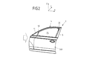
ドアフレームストリップ4が取り付けられる前に、かつ該当する場合には、ウィンドウガラスFSがドアフレーム支持体TTに取り付けられる前に、本願の場合、カバー部材5も、第2のリアフレーム部RBおよび/またはその案内ストリップ2に固定するべきである。このカバー部材5によって、車両ドアTは、Bピラーの領域において車体の外側に向かって、閉鎖されたウィンドウガラスFSと面一なものとなっている。これは、特に、組み立てられた車両ドアTを側面から図示している図2から明らかである。
Before the
図3Aから図3C,図4Aから図4B,図5Aから図5D,図6Aから図6D,図7Aから図7C,図8Aから図8Bおよび図9には、本発明に係る車両ドアアセンブリの上記の実施形態の詳細がさらに示されている。 3A to 3C, 4A to 4B, 5A to 5D, 6A to 6D, 7A to 7C, 8A to 8B and 9 show the vehicle door assembly according to the present invention. Further details of the embodiment of are shown.
この場合、図3A,図3Bおよび図3Cには、まず、ガラス側ガイド部材3aおよび3bが固定されたウィンドウガラスFSと、ウィンドウガラスのガラスアダプタAが示されている。図3Bおよび図3Cにはそれぞれ、ガラス側ガイド部材3aまたは3bが拡大して図示されている。
In this case, FIGS. 3A, 3B and 3C first show the window glass FS to which the glass
接着によりAピラー付近のガラス側縁SAに固定された(フロント)ガイド部材3aは、この場合、ウィンドウガラスFSのガラス平面に対して横方向のY方向にのみウィンドウガラスFSを案内する。この場合、フロントガラス側ガイド部材3aは基部30aを有し、この基部を介して、フロントガラス側ガイド部材3aは、フロントガラス側縁SAの近くでウィンドウガラスFSの内側に強固に結合される。この基部30aから複数の案内部31aが延びており、複数の案内部はウィンドウガラスFSの内側からL字形に突出している。この場合、これらのL字形の案内部31aはそれぞれ、フロントガラス側縁SAを越えて突出している領域を有しており、この領域を介して、フロントガラス側ガイド部材3aは案内ストリップ1の案内溝10に係合することが可能であり、この案内溝10を介して、第1の案内ストリップ1上において変位可能に案内することができる。
In this case, the (front)
ウィンドウガラスFSの反対側の(リア)ガラス側縁SBにおいて、少なくとも1つの他方の(リア)第2のガイド部材3bは、ウィンドウガラスFSの内側に接着されている。このため、リアガラス側ガイド部材3bも基部30bを有する。ウィンドウガラスFSの内側に接着された基部30bから、第2のガラス側ガイド部材3bの一部がリアガラス側縁SBを通って延びており、これにより、第2のリアガラス側ガイド部材3bは、ウィンドウガラスFSのリアガラス側縁SBを越えて突出している。この場合、リアガラス側ガイド部材3bの突出部は、2つの(本願において、立方体状の)案内部31.1bおよび31.2bを形成する。これらの案内部は、第2の案内ストリップ2の案内溝20に導入して、変位可能に保持することが可能である。この場合、案内部31.1bおよび31.2bは、リア案内ストリップ2の長手方向に対して互いに重ねられて配置されている。案内溝20に形状適合で収容される案内部31.1bおよび31.2bを介して、第2のリアガラス側ガイド部材3b、またこれにより、ウィンドウガラスFSを、第2の案内ストリップ2上でY方向(すなわち、ガラス平面に対して横方向)およびX方向(すなわち、ガラス平面と平行かつウィンドウガラスFSの調節方向に対して実質的に垂直な方向)の両方向に物理的に案内する。
At the opposite (rear) glass side edge SB of the window glass FS, at least one other (rear)
2つの案内部31.1bおよび31.2bの間において、第2のリアガラス側ガイド部材3bは、ばね部32bも形成する。ばね部を介して、第2のリアガラス側ガイド部材3bは、車両に適切に取り付けられた車両ドアTと共に、車両の長手方向に対して実質的に平行に延びるX方向に弾性的に支持されている。第2のリアガラス側ガイド部材3bと対応する第2の案内ストリップ2とをX方向に弾性当接させることにより、遊びの調節が行われる。また、弾性当接はがたつきを防止するので、ドアフレーム支持体TTに適切に取り付けられたウィンドウガラスFSとの望ましくないラトル音が抑制される。
The second rear glass
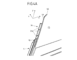
図4Aおよび図4Bに示された詳細はそれぞれ、案内ストリップ1および2の上方挿入領域に着目して、それぞれ対応する案内ストリップ1または2において既にウィンドウガラスFSに固定されたフロントガラス側ガイド部材3aおよびリアガラス側ガイド部材3bの配置を示す斜視図である。また、これらの図面には、2つの側方フレーム部RAおよびRBと、案内ストリップ1または2の各上方開放端において側方フレーム部を連結する上方フレーム部RCとを有するウィンドウフレームRがどのように後退して、ガラス側ガイド部材3aおよび3bを案内ストリップ1および2の案内溝10および20に上方から挿入できるようになっているかが示されている。この場合、図4Bにはさらに、本願の場合において、ウィンドウガラスFSがドアフレーム支持体TTに取り付けられる前に、カバー部材5がリアフレーム部RBに既に固定されていることを示している。
The details shown in FIGS. 4A and 4B focus on the upper insertion areas of the guide strips 1 and 2, respectively, and the windshield
図5Aから図5Dには、異なる視点で、一部の図面においては拡大した状態で、ウィンドウガラスFSが既に取り付けられたドアフレーム支持体TTのウィンドウフレームRのAピラー付近の領域が図示されている。この場合、上方フレーム部RCの後退部7aが、特に図5Cから明らかであり、この後退部7aにより、第1のフロントガラス側ガイド部材3aを上方フレーム部RCの側を通って案内して、上方に開口した案内ストリップ1の案内溝10に挿入させることができる。この場合において、この後退部7aは内側に向かう追加の凹部70を有し、これにより、第1のフロントガラス側ガイド部材3aの、ウィンドウガラスFSの内側から突出する案内部31aを案内溝10に、より容易に導入することができる。
5A to 5D show, from different perspectives, in an enlarged view in some drawings, a region near the A pillar of the window frame R of the door frame support TT to which the window glass FS is already attached. There is. In this case, the
また、図5Bから図5Dの図面から、フロント案内ストリップ1は、また、ギャップシール6の形の封止エレメントを固定する締結溝12を形成していることが明らかである。この場合、ギャップシール6は、ミラートライアングル11とウィンドウガラスFSとの間に必然的に生じる細隙に設けられて、フロントガラス側縁SAの領域を封止している。ギャップシール6を固定するために、ギャップシール6は、リブ状に突出しかつ案内ストリップ1の締結溝12に形状適合で収容される締結部62を有する。
It is also clear from the views of FIGS. 5B to 5D that the
図6Aから図6Dには、第2のリア案内ストリップ2における挿入領域、およびこの挿入領域における上方フレーム部RCの対応する後退部7bが図示されている。この場合、上方フレーム部RCの後退部7bは内側に凹んでおり、これにより、第2のリアガラス側ガイド部材3bを上方フレーム部RCの側を通って案内し、このガラス側ガイド部材3bをフレーム側のリア案内ストリップ2に挿入させることができる。この場合、上方に開口した第2のリア案内ストリップ2の挿入領域および上方フレーム部RCの(リア)後退部7bは、上方に開口した第1のフロント案内ストリップ1の端部および上方フレーム部RCの対応する(フロント)後退部7aと同様に、後から取り付けられるドアフレームストリップ4によって閉鎖される。
FIGS. 6A to 6D show the insertion area in the second
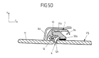
特に、図6Dの断面図において、さらに、カバー部材5が、リア側方フレーム部RBおよびリア案内ストリップ2に固定されていることが示されている。この場合、カバー部材5は支持部5.2を有し、この支持部は、リア案内ストリップ2およびリア側方フレーム部RBの背面部と、支持部上に形成されたフック状の保持部50および51を介して係合する。これにより、カバー部材5の支持部5.2は、保持部50および51を用いて、ウィンドウフレームRのリア案内ストリップ2およびリア側方フレーム部RBの両方に固定される。カバー部材5の外側から視認できる表面を形成するスクリーン5.1も、支持部5.2に固定されている。
In particular, in the sectional view of FIG. 6D, it is further shown that the
図7A,図7Bおよび図7Cには、ドアフレームストリップ4として構成された閉鎖部の更なる詳細が示されている。この閉鎖部を介して、ウィンドウガラスFSが取り付けられた後に、案内ストリップ1および2の挿入領域、ならびに上方フレーム部RCの後退部7aおよび7bが閉鎖される。この場合、ドアフレームストリップ4は、上方フレーム部RCに差し込まれている。そして、細長いドアフレームストリップ4は、適切に取り付けられた後、前部41によって、ミラートライアングル11を通って車両ドアTのシル領域BRまで延びている。この前部41は、ドアフレームストリップ4の中央部42によって後部と隣接しており、中央部は、上方フレーム部RC全体にわたって延び、かつカバー部材5の上方において後部43に移行している。したがって、ドアフレームストリップ4は、外側から視認できる車両ドアTの上縁を形成しており、この上縁も、閉鎖されたウィンドウガラスFSと面一となっている。
7A, 7B and 7C show further details of the closure configured as the
この場合、ドアフレーム支持体Tに適切に固定されたドアフレームストリップ4によって、ガラス側ガイド部材3aおよび3bが、フレーム側案内ストリップ1および2から押し上げられることが防止され、これにより、ウィンドウガラスFSは、取り付けのために、上方からのみドアフレーム支持体TTに取り付けることが可能である。さらに、少なくとも部分的にプラスチック材料、ゴム材料、または金属から製造されたドアフレームストリップ4において、上方ガラスシールが装着または一体化されている。ウィンドウガラスFSは、閉鎖時にこのガラスシールへと移動され、または少なくともガラスシールと接し、閉鎖されたウィンドウガラスFSを介して上方フレーム部RC領域においてウィンドウ開口Oを封止状態で閉鎖する。
In this case, the
図8Aの斜視図には、ガラス上縁SOのための、一体形成されたガラスシール45を有するドアフレームストリップ4が図示されている。さらに、ドアフレームストリップ4は、一体形成(例えば、射出形成または加硫)された複数(本願の場合においては、3つ)の成形部44.1,44.2および44.3を有する。この場合、ドアフレームストリップ4の前部41および中央部42の間の移行領域ならびにドアフレームストリップ4の後部43の端部領域に設けられた成形部44.2および44.3は、適切に取り付けられたドアフレームストリップ4を有するドアケースの方向(下方)に突出している。これらの突出している成形部44.2および44.3はそれぞれ、フロント案内ストリップ1またはリア案内ストリップ2の対応する案内溝10または20に上方から差し込まれており、案内溝10または20を上方から閉鎖する。ドアフレームストリップ4の前端に設けられた成形部44.1は、さらに、ミラートライアングル11の前端のシル領域BRにおけるドアフレームストリップ4と所定の形で当接する。
The perspective view of FIG. 8A shows the
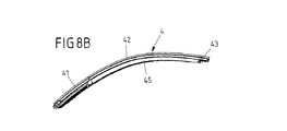
図8Bに示された変形例において、成形部44.1,44.2および44.3はいずれも、ドアフレームストリップ4に一体形成されていない。それにもかかわらず、ウィンドウガラスFSのガラス上縁SOのための、一体となったガラスシール45を有する上記のドアフレームストリップ4は、案内ストリップ1および2の挿入領域、ならびに上方フレーム部RCの後退部7aおよび7bを閉鎖する機能に加えて、閉鎖状態においては、ウィンドウガラスFSを封止する機能も果たす。
In the variant shown in FIG. 8B, none of the molding parts 44.1, 44.2 and 44.3 are integrally formed with the
図9の断面図には、典型的な構造について、図8Aおよび図8Bに対応する方法で上方フレーム部RCに取り付けられたドアフレームストリップ4がより詳細に図示されている。したがって、この場合、ドアフレームストリップ4は、硬質の(好ましくは、金属製の)インレー46を有し、このインレーを介して上方フレーム部RCに固定される。細長い硬質インレー46は、ガラスシール45を形成するプラスチック材料によって内包されている。このガラスシール45によって、シールリップによって囲まれた封止溝40が形成される。ウィンドウガラスFSが閉鎖されたとき、ウィンドウガラスFSのガラス上縁SOはこの封止溝40へと移動し、そして、シールリップがガラス内側に接して、特に、ガラス上縁SOを介して隙間風が車両内に入ることを防止する。
The cross-sectional view of FIG. 9 shows in more detail the
図10Aおよび図10Bには、本発明に係る車両ドアアセンブリの更なる実施形態が示されており、この実施形態において、ガラス側ガイド部材3aおよび3bが固定されているウィンドウガラスFSがドアフレーム支持体TTに上方から取り付けられた後に、閉鎖部4*が、ドアフレーム支持体TTのウィンドウフレームRの上方フレーム部も同時に形成する。
10A and 10B show a further embodiment of the vehicle door assembly according to the invention, in which the window glass FS to which the glass
この場合、ドア外側パネルTABを有するドアフレーム支持体TTは、上方に開口したウィンドウフレームRを有する。ウィンドウガラスFSが取り付けられる前に車両ドアTのウィンドウ開口Oを形成するために、このとき、フレーム側ガイド部材が形成または装着された側方フレーム部RAおよびRBのみが、案内ストリップ1および2の形式でドアフレーム支持体TTに既に設けられている。これにより、ガラス側ガイド部材3a,3bを、案内ストリップ1および2の対応する案内溝10,20に、支障なく、上方から装着することが可能であり、これにより、ウィンドウガラスFSを、ドアフレーム支持体TTに上方から挿入できる。ウィンドウガラスFSが、互いに協働するガラス側およびフレーム側ガイド部材1,2,3a,3bを介してドアフレーム支持体TT上で変位可能に保持されている場合、本発明において車両ドアTの硬質なウィンドウフレームRの一部を形成する閉鎖部4*は、上方から取り付けられる。
In this case, the door frame support TT having the door outer panel TAB has the window frame R opened upward. In order to form the window opening O of the vehicle door T before the window glass FS is attached, at this time, only the side frame portions RA and RB on which the frame side guide member is formed or mounted are provided on the guide strips 1 and 2. Already provided on the door frame support TT in the form. As a result, it is possible to mount the glass
この場合、上方フレーム部を形成する閉鎖部4*は、適切に取り付けられた状態において、ウィンドウ開口Oを越えて延び、かつこの開口を上方から閉鎖する細長い形状の金属を有する。フロント側方フレーム部RAおよびリア側方フレーム部RBを強固に連結するために、閉鎖部4*は、ドアフレーム支持体TTのドアケースの方向に突出する(例えばガセットプレートの形式の)連結部44.2*および44.3*を有する。これらの連結部44.2*および44.3*によって、閉鎖部4*が装着された後、閉鎖部4*は、ドアフレーム支持体TTの側方フレーム部RA,RBに強固に連結される。
In this case, the
また、この変形例において、この閉鎖部4*をドアフレーム支持体TTに取り付ける前に、閉鎖部4*がウィンドウガラスFSのガラス上縁Sのためのガラスシールを既に有するように構成することも、当然可能である。同様に、閉鎖部4*が、外装体において視認できる車両ドアTの部材を有しているもの、またはそうした部材を一体化させたものとすることも可能である。あるいは、閉鎖部4*を側方フレーム部RAおよびRBに連結した後に、別個のカバー部材を閉鎖部4*に取り付けることも可能である。
It is also possible in this variant that the
原則として、本発明において、案内ストリップ1および2に設けられた、ガラス側ガイド部材3aおよび3bを装着するための開放端が、上方フレーム部を形成する閉鎖部4*によって既に閉鎖されていることが好ましい。しかしながら、1つの可能な変更として、外装体において視認できる表面を車両ドアTの上部ドアフレームに形成する、後から取り付けられる(追加の)閉鎖部によって、対応する方法で閉鎖することが可能である。
In principle, according to the invention, the open ends of the guide strips 1 and 2 for mounting the glass
図11には、本発明に係る車両ドアアセンブリおよび本発明に係る対応の取り付け方法の基本的な原則が模式的に示されている。この場合、車両ドアTのウィンドウフレームRは、閉鎖状態において上方および/または側方の車体部分と面一である調節可能なウィンドウガラスFSを、側方で案内する2つの互いに対向するフレーム部RAおよびRBを有している。 FIG. 11 schematically shows the basic principle of the vehicle door assembly according to the invention and the corresponding mounting method according to the invention. In this case, the window frame R of the vehicle door T has two opposing frame parts RA for laterally guiding an adjustable window glass FS which is flush with the upper and / or lateral body part in the closed state. And RB.
1つの変形例によると、少なくとも1つの後退部が、これら2つの側方フレーム部RAおよびRBを連結する上方フレーム部RCに設けられる。この後退部によって、側方フレーム部RAおよびRBにおいてシル領域BRの上方に設けられた挿入領域に、ウィンドウガラスFSを上方から挿入することができる。そして、取付用の挿入領域および上方フレーム部RCの後退部を閉鎖する少なくとも1つの閉鎖部が、上方フレーム部RCに取り付けられる(特に、図1および図2を参照)。 According to a variant, at least one recess is provided in the upper frame part RC connecting these two lateral frame parts RA and RB. By this receding portion, the window glass FS can be inserted from above into the insertion area provided above the sill area BR in the side frame portions RA and RB. Then, at least one closing portion that closes the insertion area for attachment and the retreat portion of the upper frame portion RC is attached to the upper frame portion RC (in particular, see FIGS. 1 and 2).
ガラス側ガイド部材を上方から、任意でウィンドウガラスFSと共に装着することができるようにするために、上記以外の方法として、上方フレーム部RCを個別に取り付けられるようにして、車両ドアTのドアフレーム支持体TTのウィンドウフレームRが、上方から取り付けるために最初は開放されているように構成することも可能である(図10Aおよび図10Bを参照)。 In order to allow the glass-side guide member to be optionally attached together with the window glass FS from above, as an alternative method to the above, the upper frame portion RC can be individually attached to the door frame of the vehicle door T. It is also possible for the window frame R of the support TT to be initially open for mounting from above (see FIGS. 10A and 10B).
したがって、本発明に係る解決手段は、これまでに用いられていた車両ドアとは、埋め込み型ガラスの構成において、また特にそのドアフレーム支持体において相違している。よって、実際のところ、上方フレーム部RCは、各場合において図12に対応する方法で構成されており、ウィンドウガラスFSの閉鎖状態において、ウィンドウガラスFSのガラス上縁SOと面一である。対照的に、この場合、本発明に係る解決手段は、例えば、側方フレーム部RAおよびRBの領域および対応するフレーム側ガイド部材において少なくとも局所的に後退した後退部7aまたは7bが形成される上方フレーム部RCを提供する。このような変形例は、例示的に図13Aに示されている。
The solution according to the invention therefore differs from the vehicle doors used hitherto in the construction of the recessed glass and in particular in its door frame support. Thus, in fact, the upper frame part RC is in each case constructed in a manner corresponding to FIG. 12 and is flush with the glass upper edge SO of the window glass FS in the closed state of the window glass FS. In contrast, in this case, the solution according to the invention is, for example, above the region where lateral frames RA and RB and corresponding frame-side guide members are formed with at least locally retracted
1つの可能な代替例として、ウィンドウガラスFSのガラス上縁SOのほとんどの長さにわたって、また特に、実質的に領域全体にわたって後退した状態で実現された上方フレーム部RCが挙げられる。よって、上方フレーム部RCは、例えば図13Bに対応する方法で、実質的に上方フレーム部RCの長さ全体にわたって延び、かつ、上方フレーム部RCの2つの側方リブ8aおよび8bによって囲まれた後退部7cを形成する。
One possible alternative is the upper frame part RC realized over most of the length of the glass upper edge SO of the window glass FS, and in particular in a recessed manner over substantially the entire area. Thus, the upper frame part RC extends substantially over the entire length of the upper frame part RC and is surrounded by the two
図13Cに示された更なる代替例において、本発明に記載したように、上方フレーム部RCは、その長さ全体にわたって後退部7cを形成して、埋め込み型ガラスの構成において上方からガラス側ガイド部材を挿入できるようにしてもよい。
In a further alternative shown in FIG. 13C, as described in the present invention, the upper frame portion RC forms a
本発明に係る解決手段を用いて、着脱可能なドア外皮を有していない車両ドアTの閉鎖位置においてウィンドウ開口を囲む本体部品と面一となるウィンドウガラスFSを取り付けることも可能である。むしろ、従来的な二部シェル型ドア設計に従って製造された車両ドアTの場合であっても、「フラッシュガラス」または「フラッシュグレージング」ウィンドウ昇降装置に用いられるウィンドウガラスFSを設置することが可能である。この場合、ドアフレーム支持体TTはドア内皮と、これによりドア内側パネルと、ドア外皮と、これにより、ウィンドウガラスFSがドアフレーム支持体TTに取り付けられる前に、ドア外皮に強固かつ着脱不能に連結されるドア外側パネルTABとを有する。 It is also possible to use the solution according to the invention to attach a window glass FS which is flush with the body part surrounding the window opening in the closed position of the vehicle door T, which does not have a removable door skin. Rather, even in the case of a vehicle door T manufactured according to a conventional two-part shell type door design, it is possible to install the window glass FS used in "flash glass" or "flash glazing" window lifting devices. is there. In this case, the door frame support TT is the door inner skin, and thus the door inner panel, the door skin, and thus the window glass FS is firmly and non-detachably attached to the door skin before being attached to the door frame support TT. A door outer panel TAB to be connected.
1 第1の案内ストリップ(第1のフレーム側ガイド部材)
10 案内溝
11 ミラートライアングル
12 締結溝
2 第2の案内ストリップ(第1のフレーム側ガイド部材)
20 案内溝
30a,30b 基部
31a,31.1b,31.2b 案内部
32b ばね部
3a,3b ガイド部材(ガラス側ガイド部材)
4 ドアフレームストリップ(閉鎖部)
4* 上方フレーム部を形成する閉鎖部
40 封止溝
41 前部
42 中央部
43 後部
44.1,44.2,44.3 成形部
44.2*,44.3* 連結部
45 ガラスシール
46 インレー
5 カバー部材
5.1 スクリーン
5.2 支持部
50,51 保持部
6 ギャップシール(封止エレメント)
62 締結部
70 追加の凹部
7a,7b,7c 後退部
8a,8b リブ
A ガラスアダプタ
BR シル領域
FS ウィンドウガラス
O ウィンドウ開口
R ウィンドウフレーム
RA 第1の側方フレーム部
RB 第2の側方フレーム部
RC 上方フレーム部
SA,SB ガラス側縁
SO ガラス上縁
SU ガラス下縁
T 車両ドア
TAB ドア外側パネル
TT ドアフレーム支持体
1 First guide strip (first frame side guide member)
10
20
4 Door frame strip (closed part)
4 * Closing
62
Claims (22)
ドアフレーム支持体(TT)であって、前記ウィンドウ開口(O)の下にあって前記ウィンドウガラス(FS)を開くために前記ウィンドウガラス(FS)が下げ入れられるドアケースを形成し、かつ、前記ウィンドウ開口(O)において前記ドアケースの上方で互いに対向して配置された少なくとも2つの側方フレーム部(RA,RB)を有するドアフレーム支持体と、
前記側方フレーム部(RA,RB)の一方において前記ウィンドウガラス(FS)を側方で案内する第1のフレーム側ガイド部材(1)、および前記側方フレーム部(RA,RB)の他方において前記ウィンドウガラス(FS)を側方で案内する第2のフレーム側ガイド部材(2)と、
前記フレーム側ガイド部材(1,2)において前記ウィンドウガラス(FS)を変位可能に保持する第1および第2のガラス側ガイド部材(3a,3b)と、
を少なくとも備える車両ドアアセンブリにおいて、
前記第1および第2のフレーム側ガイド部材(1,2)はそれぞれ、前記ドアケースの上方に挿入領域を有し、該挿入領域は上方に開口した形状を備え、前記ガラス側ガイド部材(3a,3b)が、それぞれ対応する前記第1または第2のフレーム側ガイド部材(1,2)の前記挿入領域に上方から装着されて、前記ウィンドウガラス(FS)を前記ドアフレーム支持体(TT)に取り付けることができ、
前記第1および第2のガラス側ガイド部材(3a,3b)が装着された状態で取り付けられ、前記第1および第2のフレーム側ガイド部材(1,2)の前記挿入領域の少なくとも一方を閉鎖する少なくとも1つの閉鎖部(4,4*)が設けられることを特徴とする車両ドアアセンブリ。 A window glass (FS) adjustable by means of a vehicle window lifter, which in the closed state is above and / or laterally surrounding a window opening (O) of a vehicle door (T) which is closed by the window glass (FS). A window glass (FS) that is flush with the body,
A door frame support (TT) forming a door case below the window opening (O) into which the window glass (FS) is lowered to open the window glass (FS), and A door frame support having at least two side frame portions (RA, RB) arranged to face each other above the door case in the window opening (O);
A first frame side guide member (1) for laterally guiding the window glass (FS) in one of the side frame portions (RA, RB) and the other of the side frame portions (RA, RB) A second frame side guide member (2) for laterally guiding the window glass (FS);
First and second glass-side guide members (3a, 3b) for movably holding the window glass (FS) in the frame-side guide members (1, 2);
In a vehicle door assembly comprising at least
Wherein each of the first and second frame side guide members (1, 2) has an insertion region above the door casing, said insertion region comprises an opening shape upward, before Symbol glass side guide member ( 3a, 3b) are attached from above to the insertion regions of the corresponding first or second frame side guide members (1, 2) , and the window glass (FS) is attached to the door frame support (TT). ) Can be attached to
The first and second glass side guide members (3a, 3b) are attached in a mounted state, and at least one of the insertion regions of the first and second frame side guide members (1, 2) is closed. Vehicle door assembly, characterized in that at least one closure (4, 4 *) is provided.
前記少なくとも1つの突出部(44.2*,44.3*)が設けられて、前記閉鎖部(4,4*)を前記側方フレーム部(RA,RB)の一方に連結することを特徴とする車両ドアアセンブリ。 Vehicle door assembly according to claim 11, wherein the closure (4,4 * ) is properly mounted by the at least one projection (44.1, 44.2, 44.3), The insertion area is at least partially closed and / or covered, and / or said at least one projection (44.2 * , 44.3 * ) is provided to provide said closure (4,4 * ). Is coupled to one of the side frame portions (RA, RB).
前記ウィンドウガラス(FS)が、閉鎖状態において、前記ウィンドウガラス(FS)によって閉鎖される車両ドア(T)のウィンドウ開口(O)を囲む上方および/または側方の本体部分と面一であり、
前記ドアフレーム支持体(TT)は、前記ウィンドウガラス(FS)を開くために前記ウィンドウガラス(FS)が下げ入れられる前記ウィンドウ開口(O)の下にあるドアケースを形成し、かつ、前記ウィンドウ開口(O)において、前記ドアケースの上方において互いに対向して配置された少なくとも2つの側方フレーム部(RA,RB)を有し、
前記方法が、
前記側方フレーム部(RA,RB)の一方において、前記ウィンドウガラス(FS)を側方から案内する第1のフレーム側ガイド部材(1)と、前記側方フレーム部(RA,RB)の他方において、前記ウィンドウガラス(FS)を側方から案内する第2のフレーム側ガイド部材(2)とを有する前記ドアフレーム支持体(TT)を提供するステップと、
前記ウィンドウガラス(FS)を前記フレーム側ガイド部材(1,2)に変位可能に保持する第1および第2のガラス側ガイド部材(3a,3b)を提供するステップと、
を少なくとも備える方法において、
前記第1および第2のフレーム側ガイド部材(1,2)がそれぞれ、前記ドアケースの上方に挿入領域を有し、該挿入領域は上方に開口した形状を備え、かつ、前記第1および第2のガラス側ガイド部材(3a,3b)が、それぞれ対応する前記第1および第2のフレーム側ガイド部材(1,2)の前記挿入領域に上方から装着されて、前記ウィンドウガラス(FS)を前記ドアフレーム支持体(TT)に取り付け、
前記第1および第2のガラス側ガイド部材(3a,3b)が前記第1および第2のフレーム側ガイド部材に装着された後に、前記第1および第2のフレーム側ガイド部材(1,2)の前記挿入領域の少なくとも一方が、少なくとも1つの閉鎖部(4,4*)によって閉鎖されることを特徴とする方法。 A method of mounting a vehicle door assembly having an adjustable window glass (FS) for a vehicle window lifter and a door frame support (TT), comprising:
The window glass (FS) is, in the closed state, flush with the upper and / or lateral body part surrounding the window opening (O) of the vehicle door (T) closed by the window glass (FS),
The door frame support (TT) forms a door case under the window opening (O) into which the window glass (FS) is lowered to open the window glass (FS), and the window In the opening (O), at least two side frame portions (RA, RB) arranged to face each other above the door case,
The method is
In one of the side frame portions (RA, RB), a first frame side guide member (1) for guiding the window glass (FS) from the side and the other of the side frame portions (RA, RB). Providing a door frame support (TT) having a second frame side guide member (2) for guiding the window glass (FS) from the side,
Providing first and second glass side guide members (3a, 3b) for movably holding the window glass (FS) on the frame side guide members (1, 2);
In a method comprising at least
Each of the first and second frame-side guide members (1, 2) has an insertion region above the door case, and the insertion region has a shape that opens upward, and the first and second Two glass side guide members (3a, 3b) are attached from above to the insertion regions of the corresponding first and second frame side guide members (1, 2), respectively, and the window glass (FS) is removed. Attached to the door frame support (TT),
After the first and second glass side guide members (3a, 3b) are mounted on the first and second frame side guide members, the first and second frame side guide members (1, 2) At least one of said insertion regions of is closed by at least one closure (4, 4 * ).
前記閉鎖部(4)は、少なくとも、前記後退部(7a,7b,7c)のうちの1つの領域において、前記上方フレーム部(RC)に取り付けられることを特徴とする方法。 21. The method according to claim 20, wherein the window glass side end surface of the upper frame portion (RC) is adjacent to the end surface of at least one frame side guide member (1, 2) facing the insertion area. With respect to the part and / or the part of the adjacent side frame part (RA, RB), the retreat part (7a, 7b, 7c) retreated to the end face side of the upper frame part (RC) opposite to the end face. Have,
Method, characterized in that the closure (4) is attached to the upper frame part (RC) at least in the area of one of the recesses (7a, 7b, 7c).
前記少なくとも1つの閉鎖部(4*)は、前記上方フレーム部の少なくとも一部を形成し、かつ、
前記ドアフレーム支持体(TT)によって形成されるウィンドウフレーム(R)は、前記閉鎖部(4*)が取り付けられていないとき、上方に開口して、前記ウィンドウ開口(O)を形成していることを特徴とする方法。 21. The method according to claim 20, wherein a closure (4 * ) is attached to the first and second lateral frame portions (RA, RC) after the window glass (FS) is attached and connected. Is
The at least one closure (4 * ) forms at least part of the upper frame part, and
Window frame formed by the door frame support (TT) (R) when said closure (4 *) is not attached, opens upward direction, to form the window opening (O) The method characterized by being.
Applications Claiming Priority (3)
| Application Number | Priority Date | Filing Date | Title |
|---|---|---|---|
| DE102016200475.1 | 2016-01-15 | ||
| DE102016200475.1A DE102016200475B3 (en) | 2016-01-15 | 2016-01-15 | Vehicle door assembly with insertion areas on frame-side guide elements for a flush-mounted window concept and assembly method |
| PCT/EP2017/050363 WO2017121705A1 (en) | 2016-01-15 | 2017-01-10 | Vehicle-door assembly with insertion regions on frame-side guide elements for a flush-mounted pane concept, and mounting method |
Publications (2)
| Publication Number | Publication Date |
|---|---|
| JP2019509205A JP2019509205A (en) | 2019-04-04 |
| JP6684355B2 true JP6684355B2 (en) | 2020-04-22 |
Family
ID=57395690
Family Applications (1)
| Application Number | Title | Priority Date | Filing Date |
|---|---|---|---|
| JP2018536864A Expired - Fee Related JP6684355B2 (en) | 2016-01-15 | 2017-01-10 | A vehicle door assembly having an insertion area in a frame-side guide member, which is used for constructing an embedded glass, and a method of mounting the same |
Country Status (7)
| Country | Link |
|---|---|
| US (1) | US10843538B2 (en) |
| EP (1) | EP3402687B1 (en) |
| JP (1) | JP6684355B2 (en) |
| KR (1) | KR102110198B1 (en) |
| CN (1) | CN108463366B (en) |
| DE (1) | DE102016200475B3 (en) |
| WO (1) | WO2017121705A1 (en) |
Families Citing this family (16)
| Publication number | Priority date | Publication date | Assignee | Title |
|---|---|---|---|---|
| FR3061088B1 (en) * | 2016-12-23 | 2019-11-29 | Renault S.A.S | LATERAL GLAZING SYSTEM FOR MOTOR VEHICLE. |
| FR3062819B1 (en) * | 2017-02-15 | 2021-06-25 | Acs France Sas | FLUSHING GLASS DEVICE FOR VEHICLE DOORS, DOORS, MOTOR VEHICLES, MATERIAL MANUFACTURING PROCESS AND MONOBLOC SEALING DEVICE |
| DE102017002243A1 (en) * | 2017-03-07 | 2018-09-13 | GM Global Technology Operations LLC (n. d. Ges. d. Staates Delaware) | vehicle door |
| DE102018110218A1 (en) | 2017-06-12 | 2018-12-13 | Cqlt Saargummi Technologies S.À.R.L. | Sealing arrangement for guiding and sealing a vertically movable vehicle window pane |
| FR3070631B1 (en) * | 2017-09-04 | 2019-08-30 | Hutchinson | INSERT FOR A VEHICLE GLASS SLIDE |
| DE102018000868A1 (en) * | 2018-02-02 | 2019-08-08 | Psa Automobiles Sa | Vehicle door with height-adjustable window |
| US10583715B2 (en) * | 2018-04-26 | 2020-03-10 | Toyota Motor Engineering & Manufacturing North America, Inc. | Vehicle door cover devices and methods of using |
| DE102018124560A1 (en) | 2018-10-05 | 2020-04-09 | Bayerische Motoren Werke Aktiengesellschaft | Method for manufacturing a motor vehicle, in particular a passenger car |
| KR102575156B1 (en) * | 2018-10-15 | 2023-09-06 | 현대자동차주식회사 | Door glass capable of adjusting of position |
| FR3089461B1 (en) * | 2018-12-10 | 2020-11-13 | Hutchinson | Flush type vehicle door |
| FR3089459B1 (en) * | 2018-12-10 | 2020-11-13 | Hutchinson | Kit and method of covering a door rail of a vehicle |
| KR102552097B1 (en) * | 2018-12-14 | 2023-07-06 | 현대자동차주식회사 | Door glass assembly |
| US11052731B2 (en) | 2019-02-05 | 2021-07-06 | Volvo Car Corporation | Vehicle flush window system, a vehicle comprising same, and related assembly method |
| KR20200106396A (en) * | 2019-03-04 | 2020-09-14 | 현대자동차주식회사 | Bending structure and bending device of impact beam |
| DE102021200884A1 (en) | 2021-01-29 | 2022-08-04 | Brose Fahrzeugteile Se & Co. Kommanditgesellschaft, Bamberg | Vehicle door of a motor vehicle |
| CN216580061U (en) * | 2022-01-14 | 2022-05-24 | 瀚德(中国)汽车密封系统有限公司 | Zero-order-difference vehicle door structure and vehicle door |
Family Cites Families (65)
| Publication number | Priority date | Publication date | Assignee | Title |
|---|---|---|---|---|
| DE2551450C3 (en) | 1975-11-15 | 1980-06-04 | Daimler-Benz Ag, 7000 Stuttgart | Window guide device for retractable window panes in vehicles |
| DE2809721C2 (en) | 1978-03-07 | 1986-07-10 | Audi AG, 8070 Ingolstadt | Window guide in a door of a vehicle with a smooth outer surface in the area of the glazing |
| EP0021069B1 (en) | 1979-06-15 | 1982-10-13 | AUDI NSU AUTO UNION Aktiengesellschaft | Window strip in a vehicle |
| JPS584079A (en) | 1981-06-26 | 1983-01-11 | 日産自動車株式会社 | Lift guide mechanism of door glass |
| US4457109A (en) | 1982-02-26 | 1984-07-03 | Schlegel Corporation | Flush glass window assembly for automotive vehicle |
| DE3312473A1 (en) | 1983-04-07 | 1984-10-18 | Adam Opel AG, 6090 Rüsselsheim | ARRANGEMENT FOR A HIGH-ADJUSTABLE WINDOW WINDOW |
| DE3312470A1 (en) | 1983-04-07 | 1984-10-18 | Adam Opel AG, 6090 Rüsselsheim | HEIGHT-ADJUSTABLE WINDOW WINDOW, ESPECIALLY FOR MOTOR VEHICLES |
| US4608779A (en) * | 1984-01-11 | 1986-09-02 | Mazda Motor Corporation | Automobile door assembly |
| US4604830A (en) | 1984-01-31 | 1986-08-12 | Mazda Motor Corporation | Flush-surfaced automobile door assembly |
| JPS61169317A (en) * | 1985-01-21 | 1986-07-31 | Mazda Motor Corp | Automobile door |
| US4662115A (en) | 1985-01-21 | 1987-05-05 | Mazda Motor Corporation | Vehicle door |
| JPS6315218A (en) | 1986-07-08 | 1988-01-22 | Alps Electric Co Ltd | Manufacture of liquid crystal display element |
| FR2604660B1 (en) * | 1986-10-03 | 1990-11-30 | Mesnel Sa Ets | FLUSHING MOBILE WINDOW SYSTEM, IN PARTICULAR FOR AUTOMOBILE DOORS |
| IT1210806B (en) | 1987-06-16 | 1989-09-29 | Ferrari Eng | SUPPORT AND DRIVE STRUCTURE OF THE CRYSTALS OF A CAR BODY |
| JPH0676009B2 (en) * | 1988-01-25 | 1994-09-28 | マツダ株式会社 | Car glass structure |
| FR2634816B1 (en) | 1988-07-28 | 1990-11-02 | Hutchinson | GUIDE SLIDE FOR MOBILE ICE, ESPECIALLY ICE OR AUTOMOTIVE WINDOW |
| US4932161A (en) | 1988-11-16 | 1990-06-12 | The Standard Products Company | Four-sided flush glass assembly |
| US4920697A (en) | 1988-11-17 | 1990-05-01 | Hoover Universal Inc. | Dual drive window regulator mechanism |
| FR2642375B1 (en) | 1989-01-27 | 1994-05-13 | Mesnel Sa Ets | FLUSHING MOBILE WINDOW SYSTEM FOR A MOTOR VEHICLE DOOR, AS WELL AS WINDOW AND REINFORCED ELASTOMER PROFILE FOR USE IN SUCH A SYSTEM |
| JPH0725420Y2 (en) | 1989-07-17 | 1995-06-07 | 日本ケーブル・システム株式会社 | Sliding member for window regulator |
| DE4026215A1 (en) | 1990-08-18 | 1992-02-20 | Audi Ag | Vehicle door with window lifting mechanism - has window frame with guide rails and gaskets in which window pane is guided when raised and lowered |
| US5159781A (en) | 1990-10-04 | 1992-11-03 | Ford Motor Company | Window panel position regulating assembly |
| GB9109900D0 (en) | 1991-05-08 | 1991-07-03 | Draftex Ind Ltd | Sealing and guiding strips |
| DE69215103T2 (en) * | 1992-08-04 | 1997-06-12 | Mecaplast Sam | BRACKET FOR SEVERAL INSTALLATIONS IN A VEHICLE DOOR AND INSTALLATION METHOD FOR THE BRACKET |
| DE4437532C2 (en) | 1994-10-20 | 1996-12-12 | Brose Fahrzeugteile | Device for connecting a window lifter to the sliding window pane of a motor vehicle |
| DE19528456A1 (en) * | 1995-08-03 | 1997-02-06 | Opel Adam Ag | Retractable headrest, especially for motor vehicles |
| WO1997037099A2 (en) | 1996-03-29 | 1997-10-09 | Excel Industries, Inc. | Window regulator with improved glider assembly |
| FR2747345B1 (en) | 1996-04-12 | 2001-10-19 | Standard Products Ind | GUIDING DEVICE FOR A MOBILE WINDOW OF A MOTOR VEHICLE |
| US5732509A (en) | 1996-06-13 | 1998-03-31 | Ford Global Technologies, Inc. | Guide and sealing system vehicle window flush with body surface |
| GB9617549D0 (en) * | 1996-08-21 | 1996-10-02 | Rover Group | Vehicle door structures |
| JPH1061308A (en) | 1996-08-23 | 1998-03-03 | Delta Kogyo Co Ltd | Window regulator |
| US6141910A (en) | 1997-05-28 | 2000-11-07 | Dura Global Technologies, Inc. | Door module having a windowpane which includes brackets for attaching the windowpane to the door module and for moving the windowpane |
| DE19744810B4 (en) | 1997-10-02 | 2005-10-27 | Wagon Automotive Gmbh | Motor vehicle door with a recessed window |
| DE19826040B4 (en) * | 1998-03-05 | 2005-09-01 | Wagon Automotive Gmbh | Method for producing a glass channel frame for a shell-type vehicle door |
| JP3405216B2 (en) | 1998-07-23 | 2003-05-12 | トヨタ車体株式会社 | Wind regulator device |
| JP3656003B2 (en) * | 1999-02-18 | 2005-06-02 | 株式会社大井製作所 | Auto body structure |
| DE19946311A1 (en) * | 1999-09-28 | 2001-04-12 | Meritor Automotive Gmbh | Vehicle door |
| DE19950656A1 (en) * | 1999-10-21 | 2001-05-10 | Porsche Ag | Vehicle door, in particular motor vehicle door |
| DE19962988A1 (en) * | 1999-12-24 | 2000-05-31 | Audi Ag | Door of motor vehicle has adaptor element rigidly connected to sides of window frame, and connecting contour is provided in door body for form-fitting and connecting of adaptor element |
| US6966149B2 (en) | 2003-03-27 | 2005-11-22 | Fenelon Paul J | Window bracket for a window lift mechanism |
| JP3916145B2 (en) | 2002-07-03 | 2007-05-16 | 株式会社大井製作所 | Window regulator slider |
| JP3953410B2 (en) | 2002-11-01 | 2007-08-08 | 富士重工業株式会社 | Guide for raising and lowering window glass for vehicles |
| DE10254989B4 (en) | 2002-11-26 | 2006-05-24 | Küster Automotive Door Systems GmbH | Window lift for raising and lowering a window of a motor vehicle with a driver with a metallic insert |
| WO2004098934A1 (en) * | 2003-05-07 | 2004-11-18 | Grupo Antolin-Ingenieria, S.A. | Door module |
| JP4005593B2 (en) * | 2004-08-23 | 2007-11-07 | 本田技研工業株式会社 | Elevating door glass support structure |
| US20060059799A1 (en) | 2004-08-24 | 2006-03-23 | Cooper-Standard Automotive Inc. | Invisible division bar modular assembly |
| JP4640023B2 (en) * | 2005-08-02 | 2011-03-02 | 三菱自動車工業株式会社 | Door structure |
| DE102005052945B3 (en) | 2005-11-03 | 2007-04-05 | Michael Heidan | Clip mechanism for roof opening- and window regulator system of motor vehicle, has drive unit that is uncoupled with carrier and clip by separating unit after reaching defined position from carrier and clip |
| DE202006001767U1 (en) | 2006-02-04 | 2007-06-14 | Brose Fahrzeugteile Gmbh & Co. Kommanditgesellschaft, Coburg | Window lift for a motor vehicle |
| US7634873B2 (en) | 2006-05-12 | 2009-12-22 | Magna International, Inc. | Composite upper door sash |
| DE102006037609A1 (en) * | 2006-08-10 | 2008-02-14 | Bos Gmbh & Co. Kg | Manual window blind with automatic retraction |
| DE102006053095A1 (en) | 2006-11-10 | 2008-05-15 | Metzeler Automotive Profile Systems Gmbh | Guiding arrangement for a movable window pane, in particular of a motor vehicle |
| JP2008149849A (en) | 2006-12-15 | 2008-07-03 | Honda Motor Co Ltd | Vehicle door structure and assembling method of the vehicle door structure |
| US8322078B2 (en) * | 2010-01-13 | 2012-12-04 | Ford Global Technologies, Llc | Inner panel design for automotive door header |
| US20120025564A1 (en) | 2010-07-28 | 2012-02-02 | Magna International Inc. | Flush Glass System Module |
| KR20120100315A (en) * | 2011-03-03 | 2012-09-12 | 공주대학교 산학협력단 | Window glass weather strip for automobile door |
| DE202011050329U1 (en) * | 2011-06-01 | 2012-09-04 | Brose Fahrzeugteile Gmbh & Co. Kommanditgesellschaft, Hallstadt | vehicle door |
| US8646215B2 (en) | 2011-09-08 | 2014-02-11 | Ford Global Technologies, Llc | Flush glass assembly interfaces |
| US8650802B2 (en) | 2011-09-08 | 2014-02-18 | Ford Global Technologies, Llc | Vehicle (automobile) flush glass appearance assembly |
| EP2657440A1 (en) | 2012-04-24 | 2013-10-30 | Grupo Antolin-Ingenieria, S.A. | Attachment device for attaching a glass pane of a vehicle to a carrier of a window regulator of a vehicle, glass pane assembly, window regulator assembly, and process of assembling and disassembling |
| JP5846159B2 (en) | 2013-05-31 | 2016-01-20 | トヨタ自動車株式会社 | Window glass support structure |
| US9290083B2 (en) * | 2013-12-18 | 2016-03-22 | Ford Global Technologies, Llc | Glass sealing system |
| FR3021253A1 (en) | 2014-05-23 | 2015-11-27 | Acs France Sas | FLASHING WINDOW DEVICE FOR MOTOR VEHICLE DOOR WITH ADJUSTABLE MOBILE PANEL, DOOR AND MOTOR VEHICLE CORRESPONDING THERETO. |
| JP2016048017A (en) | 2014-08-28 | 2016-04-07 | アイシン精機株式会社 | Window glass support structure and lifting device having the window glass support structure |
| DE102014115151B3 (en) * | 2014-10-17 | 2016-02-25 | Benteler Automobiltechnik Gmbh | Method for producing a vehicle door |
-
2016
- 2016-01-15 DE DE102016200475.1A patent/DE102016200475B3/en active Active
-
2017
- 2017-01-10 JP JP2018536864A patent/JP6684355B2/en not_active Expired - Fee Related
- 2017-01-10 EP EP17700916.4A patent/EP3402687B1/en active Active
- 2017-01-10 US US15/773,918 patent/US10843538B2/en active Active
- 2017-01-10 KR KR1020187020205A patent/KR102110198B1/en active IP Right Grant
- 2017-01-10 CN CN201780006639.2A patent/CN108463366B/en active Active
- 2017-01-10 WO PCT/EP2017/050363 patent/WO2017121705A1/en active Application Filing
Also Published As
| Publication number | Publication date |
|---|---|
| US20180339576A1 (en) | 2018-11-29 |
| WO2017121705A1 (en) | 2017-07-20 |
| DE102016200475B3 (en) | 2016-12-15 |
| KR102110198B1 (en) | 2020-05-14 |
| EP3402687A1 (en) | 2018-11-21 |
| JP2019509205A (en) | 2019-04-04 |
| CN108463366A (en) | 2018-08-28 |
| US10843538B2 (en) | 2020-11-24 |
| CN108463366B (en) | 2021-06-04 |
| KR20180094083A (en) | 2018-08-22 |
| EP3402687B1 (en) | 2021-05-12 |
Similar Documents
| Publication | Publication Date | Title |
|---|---|---|
| JP6684355B2 (en) | A vehicle door assembly having an insertion area in a frame-side guide member, which is used for constructing an embedded glass, and a method of mounting the same | |
| KR102634394B1 (en) | Door glass of vehicle with easy position setting and mehod for assembling of the door glass | |
| KR101209499B1 (en) | Unit support for a motor vehicle door | |
| EP1561619B1 (en) | Vehicle door with slidable window glass | |
| JP2010509119A (en) | Guide structure for movable window glass especially used in automobiles | |
| US8869457B2 (en) | Assembly structure of weather strip | |
| EP2607126B1 (en) | Glass-run retainer for automobile door and door structure of automobile | |
| JP2018535865A (en) | Flush glazing device for vehicle door, door, automobile, hermetic device, and corresponding manufacturing method | |
| WO2011014684A1 (en) | Adjustable glass assembly | |
| JP2010018130A (en) | Seal member of automobile door | |
| US7472943B2 (en) | Window pane assembly and bodywork element for a vehicle | |
| KR100333287B1 (en) | weatherstrip mounting structure for supporting fixed glass of automobile door | |
| JPS6022198Y2 (en) | automotive glass launch channel | |
| RU2719069C2 (en) | Compactor for car door, car door, comprising two interconnected sealants, and vehicle | |
| JP4177279B2 (en) | Support structure for automotive window glass | |
| JP7198592B2 (en) | Automobile door glass elevating structure | |
| KR101619397B1 (en) | Door structure for motor vehicle | |
| KR100463161B1 (en) | Door frame sealing means of automobile | |
| US11254198B2 (en) | Automobile door sealing member | |
| JP4264797B2 (en) | Body seal structure | |
| JP4419798B2 (en) | Method for producing weather strip for fixed glass | |
| JP6491038B2 (en) | Vehicle sealant | |
| JP3619126B2 (en) | Makeup structure for automotive side doors | |
| JP5437433B2 (en) | Automotive door seal structure | |
| JPS6012736Y2 (en) | Automotive side door corner bracket mounting structure |
Legal Events
| Date | Code | Title | Description |
|---|---|---|---|
| A621 | Written request for application examination |
Free format text: JAPANESE INTERMEDIATE CODE: A621 Effective date: 20180912 |
|
| A977 | Report on retrieval |
Free format text: JAPANESE INTERMEDIATE CODE: A971007 Effective date: 20190716 |
|
| A131 | Notification of reasons for refusal |
Free format text: JAPANESE INTERMEDIATE CODE: A131 Effective date: 20190730 |
|
| A521 | Request for written amendment filed |
Free format text: JAPANESE INTERMEDIATE CODE: A523 Effective date: 20191024 |
|
| TRDD | Decision of grant or rejection written | ||
| A01 | Written decision to grant a patent or to grant a registration (utility model) |
Free format text: JAPANESE INTERMEDIATE CODE: A01 Effective date: 20200317 |
|
| A61 | First payment of annual fees (during grant procedure) |
Free format text: JAPANESE INTERMEDIATE CODE: A61 Effective date: 20200327 |
|
| R150 | Certificate of patent or registration of utility model |
Ref document number: 6684355 Country of ref document: JP Free format text: JAPANESE INTERMEDIATE CODE: R150 |
|
| LAPS | Cancellation because of no payment of annual fees |