JP6678765B2 - Clamp mounting device, clamp mounting system and clamp mounting method - Google Patents
Clamp mounting device, clamp mounting system and clamp mounting method Download PDFInfo
- Publication number
- JP6678765B2 JP6678765B2 JP2018550179A JP2018550179A JP6678765B2 JP 6678765 B2 JP6678765 B2 JP 6678765B2 JP 2018550179 A JP2018550179 A JP 2018550179A JP 2018550179 A JP2018550179 A JP 2018550179A JP 6678765 B2 JP6678765 B2 JP 6678765B2
- Authority
- JP
- Japan
- Prior art keywords
- clamp
- work
- plate
- pedestal
- arm
- Prior art date
- Legal status (The legal status is an assumption and is not a legal conclusion. Google has not performed a legal analysis and makes no representation as to the accuracy of the status listed.)
- Active
Links
Images


Classifications
-
- B—PERFORMING OPERATIONS; TRANSPORTING
- B25—HAND TOOLS; PORTABLE POWER-DRIVEN TOOLS; MANIPULATORS
- B25J—MANIPULATORS; CHAMBERS PROVIDED WITH MANIPULATION DEVICES
- B25J9/00—Programme-controlled manipulators
- B25J9/16—Programme controls
- B25J9/1628—Programme controls characterised by the control loop
- B25J9/1633—Programme controls characterised by the control loop compliant, force, torque control, e.g. combined with position control
-
- B—PERFORMING OPERATIONS; TRANSPORTING
- B25—HAND TOOLS; PORTABLE POWER-DRIVEN TOOLS; MANIPULATORS
- B25J—MANIPULATORS; CHAMBERS PROVIDED WITH MANIPULATION DEVICES
- B25J9/00—Programme-controlled manipulators
- B25J9/16—Programme controls
- B25J9/1615—Programme controls characterised by special kind of manipulator, e.g. planar, scara, gantry, cantilever, space, closed chain, passive/active joints and tendon driven manipulators
-
- B—PERFORMING OPERATIONS; TRANSPORTING
- B25—HAND TOOLS; PORTABLE POWER-DRIVEN TOOLS; MANIPULATORS
- B25J—MANIPULATORS; CHAMBERS PROVIDED WITH MANIPULATION DEVICES
- B25J13/00—Controls for manipulators
- B25J13/08—Controls for manipulators by means of sensing devices, e.g. viewing or touching devices
- B25J13/088—Controls for manipulators by means of sensing devices, e.g. viewing or touching devices with position, velocity or acceleration sensors
- B25J13/089—Determining the position of the robot with reference to its environment
-
- B—PERFORMING OPERATIONS; TRANSPORTING
- B25—HAND TOOLS; PORTABLE POWER-DRIVEN TOOLS; MANIPULATORS
- B25J—MANIPULATORS; CHAMBERS PROVIDED WITH MANIPULATION DEVICES
- B25J19/00—Accessories fitted to manipulators, e.g. for monitoring, for viewing; Safety devices combined with or specially adapted for use in connection with manipulators
- B25J19/02—Sensing devices
- B25J19/021—Optical sensing devices
- B25J19/022—Optical sensing devices using lasers
-
- B—PERFORMING OPERATIONS; TRANSPORTING
- B64—AIRCRAFT; AVIATION; COSMONAUTICS
- B64F—GROUND OR AIRCRAFT-CARRIER-DECK INSTALLATIONS SPECIALLY ADAPTED FOR USE IN CONNECTION WITH AIRCRAFT; DESIGNING, MANUFACTURING, ASSEMBLING, CLEANING, MAINTAINING OR REPAIRING AIRCRAFT, NOT OTHERWISE PROVIDED FOR; HANDLING, TRANSPORTING, TESTING OR INSPECTING AIRCRAFT COMPONENTS, NOT OTHERWISE PROVIDED FOR
- B64F5/00—Designing, manufacturing, assembling, cleaning, maintaining or repairing aircraft, not otherwise provided for; Handling, transporting, testing or inspecting aircraft components, not otherwise provided for
- B64F5/10—Manufacturing or assembling aircraft, e.g. jigs therefor
-
- G—PHYSICS
- G05—CONTROLLING; REGULATING
- G05B—CONTROL OR REGULATING SYSTEMS IN GENERAL; FUNCTIONAL ELEMENTS OF SUCH SYSTEMS; MONITORING OR TESTING ARRANGEMENTS FOR SUCH SYSTEMS OR ELEMENTS
- G05B19/00—Programme-control systems
- G05B19/02—Programme-control systems electric
- G05B19/18—Numerical control [NC], i.e. automatically operating machines, in particular machine tools, e.g. in a manufacturing environment, so as to execute positioning, movement or co-ordinated operations by means of programme data in numerical form
- G05B19/19—Numerical control [NC], i.e. automatically operating machines, in particular machine tools, e.g. in a manufacturing environment, so as to execute positioning, movement or co-ordinated operations by means of programme data in numerical form characterised by positioning or contouring control systems, e.g. to control position from one programmed point to another or to control movement along a programmed continuous path
-
- G—PHYSICS
- G05—CONTROLLING; REGULATING
- G05B—CONTROL OR REGULATING SYSTEMS IN GENERAL; FUNCTIONAL ELEMENTS OF SUCH SYSTEMS; MONITORING OR TESTING ARRANGEMENTS FOR SUCH SYSTEMS OR ELEMENTS
- G05B2219/00—Program-control systems
- G05B2219/30—Nc systems
- G05B2219/45—Nc applications
- G05B2219/45071—Aircraft, airplane, ship cleaning manipulator, paint stripping
-
- G—PHYSICS
- G05—CONTROLLING; REGULATING
- G05B—CONTROL OR REGULATING SYSTEMS IN GENERAL; FUNCTIONAL ELEMENTS OF SUCH SYSTEMS; MONITORING OR TESTING ARRANGEMENTS FOR SUCH SYSTEMS OR ELEMENTS
- G05B2219/00—Program-control systems
- G05B2219/30—Nc systems
- G05B2219/49—Nc machine tool, till multiple
- G05B2219/49129—Clamps are movable along rod to desired positions
-
- G—PHYSICS
- G05—CONTROLLING; REGULATING
- G05B—CONTROL OR REGULATING SYSTEMS IN GENERAL; FUNCTIONAL ELEMENTS OF SUCH SYSTEMS; MONITORING OR TESTING ARRANGEMENTS FOR SUCH SYSTEMS OR ELEMENTS
- G05B2219/00—Program-control systems
- G05B2219/30—Nc systems
- G05B2219/49—Nc machine tool, till multiple
- G05B2219/49132—Control fixed clamping force
-
- G—PHYSICS
- G05—CONTROLLING; REGULATING
- G05B—CONTROL OR REGULATING SYSTEMS IN GENERAL; FUNCTIONAL ELEMENTS OF SUCH SYSTEMS; MONITORING OR TESTING ARRANGEMENTS FOR SUCH SYSTEMS OR ELEMENTS
- G05B2219/00—Program-control systems
- G05B2219/30—Nc systems
- G05B2219/50—Machine tool, machine tool null till machine tool work handling
- G05B2219/50127—Modular fixture, use of clamps and locators, the latter also for positioning
Description
本発明は、クランプ取付け装置、クランプ取付けシステム及びクランプ取付け方法に関する。 The present invention relates to a clamp mounting device, a clamp mounting system, and a clamp mounting method.
CFRP(Carbon Fiber Reinforced Plastics)製の細長い製品の製造工程には、所望の形状で硬化させるため、製品を加圧しながら熱硬化を行う工程が存在する。この熱硬化には、高温高圧に対応するオートクレーブなどが用いられる。航空機の翼に使用されるストリンガの場合、このCFRP製品は、10m以上の長さを有し、複雑な曲面に形成される。このため、熱硬化中に、このCFRP製品を複数個所で加圧する必要がある。この製品を加圧するために、クランプ等で締め付ける方法が考えられる。 In a manufacturing process of an elongated product made of CFRP (Carbon Fiber Reinforced Plastics), there is a process of performing thermal curing while pressing the product in order to cure the product in a desired shape. For this heat curing, an autoclave or the like corresponding to high temperature and high pressure is used. For stringers used in aircraft wings, this CFRP product has a length of 10 m or more and is formed into a complex curved surface. For this reason, it is necessary to pressurize this CFRP product at a plurality of locations during thermosetting. In order to pressurize this product, a method of fastening with a clamp or the like is conceivable.
特許文献1にロボットアームを用いて製品を固定する装置が開示されている。この装置は製品に開けられた孔と嵌合するロケールピンを備える。この装置は、この製品の孔にロケールピンを貫通させることで、ロケールピンの先端からクランプアームが突出し製品を固定する。 Patent Document 1 discloses an apparatus for fixing a product using a robot arm. The device includes a locale pin that mates with a hole drilled in the product. In this device, the locale pin is passed through the hole of the product, so that the clamp arm projects from the tip of the locale pin to fix the product.
特許文献1に記載の装置では製品に孔をあける必要があるほか、締め付けた状態を維持したまま、熱硬化を施すのは難しい。 In the device described in Patent Literature 1, it is necessary to make a hole in the product, and it is difficult to perform thermosetting while maintaining the tightened state.
上記状況に鑑み、本発明はクランプ取付け装置、クランプ取付けシステム及びクランプ取付け方法を提供することを目的とする。他の目的・効果は、以下の説明から明らかになるであろう。 In view of the above situation, an object of the present invention is to provide a clamp mounting device, a clamp mounting system and a clamp mounting method. Other objects and advantages will become apparent from the following description.
上記目的を達成するため、本発明の第1の態様に係るクランプ取付け装置は、回転台を有するロボットアーム台座と、ロボットアーム台座の回転台上に設置され、複数のアームと複数の関節を有するロボットアームと、複数のアームのうちの最先端のアームに取付けられたロボットハンドと、制御部とを備える。ロボットハンドは、クランプを把持するクランプ把持部と、ワークに挟力を付与するように、クランプの螺合部を締め付ける締付け部と、クランプの所定部材の位置データを収集する計測部とを備える。制御部は、クランプを把持するようにクランプ把持部を制御する。 In order to achieve the above object, a clamp mounting device according to a first aspect of the present invention is provided with a robot arm pedestal having a turntable, and installed on the turntable of the robot arm pedestal and having a plurality of arms and a plurality of joints. The robot includes a robot arm, a robot hand attached to the most advanced arm of the plurality of arms, and a control unit. The robot hand includes a clamp gripper that grips the clamp, a tightening unit that tightens a screw portion of the clamp so as to apply a clamping force to the work, and a measuring unit that collects position data of a predetermined member of the clamp. The control unit controls the clamp holding unit to hold the clamp.
また、クランプが把持されている状態で、ワークが置かれたワーク台座の第1の所定の位置にクランプが搬送されるように、クランプの結合部がワーク台座の結合部に結合されるように、回転台と、ロボットアームの複数の関節と、ロボットハンドとを制御する。さらに、クランプとワーク台座とが結合されている状態で、計測部から取得される位置データに基づいて挟力を計算し、計算された挟力が所定の値になるように、締付け部を制御する。 In a state where the clamp is gripped, the coupling portion of the clamp is coupled to the coupling portion of the work pedestal so that the clamp is transported to the first predetermined position of the workpiece pedestal on which the workpiece is placed. , A turntable, a plurality of joints of a robot arm, and a robot hand. Further, in a state where the clamp and the work pedestal are connected, a clamping force is calculated based on the position data obtained from the measuring unit, and the clamping unit is controlled so that the calculated clamping force becomes a predetermined value. I do.
クランプが、フレームと、フレームと螺合して延びるネジ部と、ネジ部に接続され、ワークに挟力を付与する弾性部とを備えている場合、制御部は、クランプとワーク台座とが結合されている状態で、計算された挟力が所定の値になるように、締付け部がネジ部を締め付けるように締付け部を制御してもよい。 When the clamp includes a frame, a screw portion that is screwed with the frame and extends, and an elastic portion that is connected to the screw portion and applies a clamping force to the work, the control portion is configured such that the clamp and the work base are connected to each other. In this state, the tightening unit may be controlled such that the tightening unit tightens the screw unit so that the calculated pinching force becomes a predetermined value.
弾性部が、バネと、バネの一端にネジ部に接続されるように設けられたバネ上板と、バネの他端に設けられたバネ下板とを備えている場合、バネ下板がワークに弾性挟力を付与してもよい。 When the elastic portion includes a spring, an upper spring plate provided at one end of the spring so as to be connected to the screw portion, and a lower spring plate provided at the other end of the spring, the lower spring plate is a work piece. May be provided with an elastic clamping force.
計測部は、バネ上板とバネ下板の位置データを計測するレーザーセンサ部を有してもよい。 The measurement unit may include a laser sensor unit that measures position data of the sprung plate and the unsprung plate.
ネジ部の上端には頭部が形成されている場合、締付け部は、頭部を駆動するナットランナを有してもよい。 When a head is formed at the upper end of the screw portion, the fastening portion may include a nut runner that drives the head.
クランプ把持部は、クランプを把持する平行チャックを備えていてもよい。 The clamp gripper may include a parallel chuck that grips the clamp.
ワーク台座が複数の突起を有し、クランプがフレームに取付けられ、複数の突起にそれぞれ係合される複数のフックを有してもよい。 The work pedestal may have a plurality of protrusions, and the clamp may be attached to the frame and have a plurality of hooks respectively engaged with the plurality of protrusions.
本発明の第2の態様に係るクランプ取付けシステムは、前述のクランプ取付け装置と、ワークの長手方向である第1方向に延びる第1レールと、第1方向に直交する第2方向に延びる第2レールとを備える。ロボットアーム台座は、第1レール上を走行するための第1移動機構と、第2レール上を走行するための第2移動機構とを備える。制御部は、第1移動機構と第2移動機構を駆動してロボットアーム台座を所定の位置に移動させる。 A clamp mounting system according to a second aspect of the present invention includes the above-described clamp mounting device, a first rail extending in a first direction that is a longitudinal direction of the workpiece, and a second rail extending in a second direction orthogonal to the first direction. A rail. The robot arm pedestal includes a first moving mechanism for traveling on the first rail and a second moving mechanism for traveling on the second rail. The control unit drives the first moving mechanism and the second moving mechanism to move the robot arm base to a predetermined position.
本発明の第3の態様に係るクランプ取付け方法は、前述のクレーム取付け装置において、回転台と、複数の関節とを駆動してロボットハンドを第1クランプとしてのクランプの上方に移動させる。次に、ロボットハンドを下げて、クランプ把持部により第1クランプを把持する。第1クランプが把持されている状態で、第1クランプを持ち上げ、ワークが置かれたワーク台座の第1の所定の位置に第1クランプを搬送する。ロボットハンドを下げて、第1クランプの結合部がワーク台座の結合部に結合されるように、ロボットハンドを水平面内で動かす。第1クランプとワーク台座とが結合されている状態で、計測部から取得される位置データに基づいて挟力を計算する。計算された挟力が所定の値になるように、締付け部を駆動する。 In the clamp mounting method according to the third aspect of the present invention, in the above-described claim mounting device, the rotary table and the plurality of joints are driven to move the robot hand above the clamp as the first clamp. Next, the robot hand is lowered, and the first clamp is gripped by the clamp gripper. While the first clamp is being held, the first clamp is lifted, and the first clamp is transported to a first predetermined position on the work base on which the work is placed. The robot hand is lowered, and the robot hand is moved in a horizontal plane such that the joint of the first clamp is joined to the joint of the work pedestal. In a state where the first clamp and the work pedestal are connected, the clamping force is calculated based on the position data acquired from the measurement unit. The tightening unit is driven so that the calculated pinching force becomes a predetermined value.
前述のクランプ取付け方法は、前述のクランプ取付けシステムにおいて、さらに、第1クランプの取付けが終了したとき、第1クランプを放すようにクランプ把持部を制御してもよい。また、第2移動機構を駆動してロボットアーム台座を第1クランプ取出し前の位置に移動させてもよい。また、第1移動機構を駆動してロボットアームを第2クランプの取り出し位置に移動させてもよい。 In the above-described clamp mounting method, in the above-described clamp mounting system, when the mounting of the first clamp is completed, the clamp holding portion may be controlled so as to release the first clamp. Further, the second moving mechanism may be driven to move the robot arm pedestal to a position before the removal of the first clamp. Further, the first moving mechanism may be driven to move the robot arm to a position where the second clamp is taken out.
本発明によれば、クランプを自動で取付け、取り外すことができるとともに、クランプを取り付けた状態で熱硬化等を行えるという利点がある。 ADVANTAGE OF THE INVENTION According to this invention, there exists an advantage that a clamp can be automatically attached and detached, and heat hardening etc. can be performed in the state which attached the clamp.
(クランプの構造) 本発明に係るクランプ50の構造を、図5を用いて説明する。クランプ50の構造を説明するにあたり、図5の紙面右方向をy方向、紙面上方向をz方向、紙面に直交する手前方向をx方向として説明する。また、+z方向を上、−z方向を下として説明する。他の図面においても、図5のx方向、y方向、z方向を基準に、各図面のx方向、y方向、z方向として説明する。なお、下方向は、あくまでも−z方向を示すもので、重力方向を示すものではない。
(Structure of Clamp) The structure of the
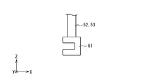
図5に示されるように、クランプ50は、横板部51と、第1腕部52と、第2腕部53と、締め付けネジ54と、バネ上板55と、バネ56と、バネ下板57と、接続板58とを備えている。
As shown in FIG. 5, the
横板部51は、y方向に延伸する平板状に形成されており、y方向の中心位置にネジ穴60を備えている。
The
締め付けネジ54は、ネジ山を有し、横板部51のネジ穴60に螺合するように設けられている。締め付けネジ54を回転させることで、締め付けネジ54は横板部51に対して上下方向(z方向)に移動する。また、締め付けネジ54は上端に6角状の頭部59を備えている。
The
バネ上板55は、平板状に形成され、その上面が締め付けネジ54の下端に接続されている。このため、締め付けネジ54を回転させることで、バネ上板55は横板部51に対して相対的に上下方向に移動する。また、バネ上板55は、締め付けネジ54に対してx−y平面で回転できるように設けられている。
The sprung
バネ56の上端は、バネ上板55の下面に接続されている。
The upper end of the
バネ下板57は、平板状に形成され、その上面がバネ56の下端に接続されている。
The
第1腕部52の上端は横板部51の−y方向端部に接続されている。第2腕部53の上端は横板部51の+y方向端部に接続されている。図6に示されるように、第1腕部52、第2腕部53の下端にはフック61が形成されている。このフック61を引っ掛けることによりクランプ50が支持されることができる。
The upper end of the
図5に示されるように、接続板58は、平板状に形成され、+y方向端部がバネ下板57に接続されている。接続板58の−y方向端部で第1腕部52が貫通し、接続板58は、第1腕部52に対して上下にスライドするように形成されている。これにより、締め付けネジ54を回転させた場合に上下方向へのバネ下板57の移動にあわせて、接続板58も上下方向に移動する。また、接続板58の端部を第1腕部52が貫通しているので、バネ下板57は回転しない。つまり、締め付けネジ54の回転が、バネ上板55とバネ56を介して、バネ下板57を回転させようとしても、接続板58により、バネ下板57の回転は防止される。
As shown in FIG. 5, the
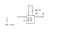
(クランプの使用方法) 図7に示されるように、クランプ50は、ワーク台座70の上に置かれているワーク80を加圧するために使用される。
(How to Use Clamp) As shown in FIG. 7, the
ここで、ワーク台座70は、結合部71と、台側板72と、台73とを備えている。
Here, the
台73はワーク80が置かれる場所である。このため、ワーク80の長さに合わせて、台73はx方向に延伸している。
The table 73 is a place where the
台側板72は台73の両側に固定されている。台73と同様に、ワーク80の長さに合わせて、台側板72もx方向に延伸している。また、台側板72の上端は台73よりも上方に位置する。
The
結合部71は、円柱形状を有し、台側板72の上端部で台側板72を貫通するように設けられている。結合部71は、クランプ50を取り付ける位置に合わせて設けられている。
The
クランプ50は、図8に示されるように、ワーク台座70に置かれているワーク80に取付けられる。
As shown in FIG. 8, the
クランプ50をワーク80に取付けるためには、まず、クランプ50の第1腕部と第2腕部との下端に設けられたフック61が、図9に示されるように、ワーク台座70の結合部71に引っ掛けられる。
In order to attach the
その後、頭部59に回転力を加えることで、締め付けネジ54が回転させられる。これにより、バネ上板55、バネ56、バネ下板57は下方に移動する。ワーク80とバネ下板57が接触すると、バネ下板57は下方に移動できなくなる。このため、さらに締め付けネジ54が回転させられると、横板部51と締め付けネジ54との螺合部は締め付けられる。その結果、バネ上板55は下方に移動し、バネ56が縮む。このため、バネ56は、バネ下板57を介してワーク80を押し付けることになる。つまり、ワーク80は、ワーク台座70とバネ下板57とにより挟まれている。
Thereafter, the tightening
このようにして、クランプ50がワーク80に取付けられ、ワーク80は加圧される。
Thus, the
(クランプ取付け装置の構造) クランプ50の取り付け、取外しに用いられるクランプ取付け装置1の構造を、図1を用いて説明する。
(Structure of Clamp Mounting Apparatus) The structure of the clamp mounting apparatus 1 used for mounting and removing the
図1に示されるように、クランプ取付け装置1は、支持台10と、第1レール11と、第2レール支持台12と、第2レール13と、ロボットアーム14と、ロボットハンド15とを備えている。
As shown in FIG. 1, the clamp mounting device 1 includes a
支持台10は、クランプ取
付け装置1を支える。支持台10はx方向に延伸し、クランプが取り付けられるワーク80より長い。 The
第1レール11は支持台10の上側に固定されている。第1レール11はx方向に延伸し、支持台10と同様に、クランプが取り付けられるワーク80より長い。
The
第2レール支持台12は、第1レール11の上側に配置され、第1レール11に沿って移動できる構造を有する。このため、第2レール支持台12は、第1レール11の長さ、つまりクランプが取り付けられるワーク80の長さを超えて、x方向に移動することができる。
The
第2レール13は第2レール支持台12の上側に固定されている。第2レール13は第1レール11と直交するy方向に延伸されている。第2レール13のy方向の長さは、ワーク80の幅と、ワーク80を横に並べる数とを基準に決定されている。
The
ロボットアーム台座20は、第2レール13の上側に配置され、ロボットアーム14を支える。このため、ロボットアーム14は、図2に示されるように、第2レール13に沿ってy方向に移動できる構造を有する。これにより、ワーク80を横に複数並べても、第2レール13がy方向に十分な長さを有することで、並べられた各ワークにクランプを取り付けることができる。また、第2レール支持台12が第1レール11に沿ってx方向に移動するため、ロボットアームも同様にx方向に移動することができる。これにより、細長いワークの任意の位置にクランプを取り付けることができる。
The
ロボットアーム14は、第1アーム21と、第2アーム22と、第3アーム23と、第4アーム24と、第5アーム25とを備えている。
The
図1に示されるように、第1アーム21は、ロボットアーム台座20の上側に配置されている。第1アーム21は、ロボットアーム台座20との接続部分である第1関節201を中心に、図1の矢印101の方向、つまりx−y平面において回転可能なように設けられている。
As shown in FIG. 1, the
図1に示されるように、第2アーム22は一方向に延伸する形状である。第2アーム22の端部は、第1アーム21に接続され、他端部は第3アーム23に接続されている。図1の状態で、第2アーム22は、第1アーム21との接続部分である第2関節202を中心に、図1の矢印102の方向、つまりz−x平面において回転可能なように設けられている。つまり、図1の状態から第1アーム21がロボットアーム台座20に対して90°回転すると、第2アーム22の回転面はy−z平面になる。これにより、第2アーム22の延伸方向は、少なくとも上方(+z方向)であれば、x−y平面との成す角を任意に調整することができる。
As shown in FIG. 1, the
第3アーム23は、図1の状態で、第2アーム22との接続部分である第3関節203を中心に、図1の矢印103の方向、つまりz−x平面において回転可能なように設けられている。
The
図1に示されるように、第4アーム24は一方向に延伸する形状である。第4アーム24の端部は、第3アーム23に接続され、他端部は第5アーム25に接続されている。第4アーム24の延伸方向は、第2アーム22の回転面内の方向である。つまり、第3アーム23と第2アーム22との接続部分である第3関節203が回転することで、第2アーム22と第4アーム24との成す角が変化する。また、第4アーム24は、図1の状態で、第3アーム23との接続部分である第4関節204を中心に、図1の矢印104の方向、つまりy−z平面において回転可能なように設けられている。
As shown in FIG. 1, the
図3の状態で、第5アーム25は、第4アーム24との接続部分である第5関節205を中心に、図3の矢印106の方向、つまりz−x平面において回転可能なように設けられている。こうして、第5アーム25と第4アーム24との接続部分を回転させることで、第5アーム25と第4アーム24との成す角が変化する。また、第3アーム23と第4アーム24との接続部分である第4関節204を、図3の状態から90°回転させることで、第5アーム25はx−y平面において回転可能になる。つまり、図3に示されるように、第5アーム25の先端部が第4アーム24との接続部分である第5関節205に対して下側にある状態から、−y方向、又は、+y方向に移動する。
In the state of FIG. 3, the
このように、ロボットアーム14の各関節の回転を制御することにより、ロボットアーム14の最先端、つまり第5アーム25の先端部は、ロボットアーム台座20に対する位置、角度を制御することができる。また、図3の状態で、第5アーム25の先端部は、端面の中心である第6関節206を軸に、図3の矢印107の方向、つまりx−y平面において回転可能なように設けられている。
Thus, by controlling the rotation of each joint of the
図3に示されるように、ロボットハンド15は、横板30、34と、縦板31、33、35と、ナットランナ支持部32と、平行チャック16と、ナットランナ17、第1レーザーセンサ18、第2レーザーセンサ19とを備える。
As shown in FIG. 3, the
横板30はx方向に延伸された平板状に形成されている。横板30の−x方向の端部の上面は、ロボットアーム14の第5アーム25の先端に固定されている。つまり、ロボットアーム14の各アームの接続箇所の回転を制御することで、ロボットハンド15は、ロボットアーム台座20に対する位置、角度を制御することができる。また、第6関節206を軸に第5アーム25の先端部を回転させることで、図3の状態で、横板30は、図3の矢印107の方向、つまりx−y平面において回転することができる。
The
縦板31はz方向に延伸する平板状に形成されている。縦板31の下端は、横板30と直交するように、横板30の+x方向の端に固定されている。
The
縦板31の+x方向側面に、ナットランナ支持部32が配置されている。ナットランナ支持部32は、縦板31に対して上下方向にスライドする構造を有する。
A nut
ナットランナ17は、ナットランナ支持部32に支持されている。ナットランナ支持部32が縦板31に対して上下にスライドすることで、ナットランナ17も上下方向に移動する。また、ナットランナ17のソケット41が下側になるように配置されている。ナットランナ17はソケット41の回転を制御する。つまり、ナットランナ17はソケット41にボルトなどを嵌合させ、そのボルトなどを回すことができる。
The
縦板33はz方向に延伸した平板状に形成されている。縦板33の上端は、横板30と直交するように、横板30の下面の中央に固定されている。
The
横板34はx方向に延伸する平板状に形成されている。横板34の−x方向の端部は、縦板33と直交するように、縦板33の下端に固定されている。
The
縦板35はz方向に延伸する平板状に形成されている。縦板35の上端は、横板34と直交するように、横板34の下面の中央に固定されている。
The
平行チャック16は、縦板35の下端部に支持されている。図4に示されるように、平行チャック16は、可動部がy方向に伸縮することで、平行チャック16の下端を開閉する。平行チャック16は下端にクランプを挟み把持する。
The
図3に示されるように、第1レーザーセンサ18、第2レーザーセンサ19は横板34の+x方向の端部に配置されている。ここで、横板34の+x方向端部は、ナットランナ17が下方に移動しても接触しないように、ナットランナ17の位置よりも−y方向、つまり紙面手前方向にずれている。横板34の+x方向の端部から−x方向に向かい、第2レーザーセンサ19、第1レーザーセンサ18の順番で配置されている。
As shown in FIG. 3, the
図10に示されるように、第1レーザーセンサ18、第2レーザーセンサ19は、クランプ50を取り付ける作業時、又は取り外し作業時に使用される。第1レーザーセンサ18はバネ上板55の位置データ、つまりバネ上板55までの距離を計測する。また、第2レーザーセンサ19はバネ下板57の位置データ、つまりバネ下板57までの距離を計測する。それぞれの計測値の差から、バネ56の長さを算出する。計算された長さに基づいて、挟力を知ることができる。
As shown in FIG. 10, the
また、クランプ取付け装置1は制御装置1000を備える。制御装置1000は、第1レール11における第2レール支持台12の位置、第2レール13におけるロボットアーム14の位置、ロボットアーム14の各アームの接続部分の角度、ナットランナ支持部32のスライド位置、ナットランナ17の回転、平行チャック16の開閉を制御する。
The clamp mounting device 1 includes a
制御装置1000は、中央処理装置(CPU)、記憶装置、メモリを備える。
The
記憶装置に、クランプ取付け装置1への命令が格納されている。 Instructions for the clamp mounting device 1 are stored in the storage device.
CPUは記憶装置からクランプ取付け装置1への命令を読み出す。CPUは、読み出した命令に従い、クランプ取付け装置1の各部の制御を行う。 The CPU reads a command to the clamp mounting device 1 from the storage device. The CPU controls each part of the clamp mounting device 1 according to the read command.
メモリは、CPUが記憶装置から読み出した命令に基づきクランプ取付け装置1の各部を制御する際に、一時的なデータを格納するために利用される。 The memory is used to store temporary data when the CPU controls each part of the clamp mounting device 1 based on a command read from the storage device.
(クランプの取付け方法) 図7に示されるように、ワーク台座70に置かれているワーク80に、クランプ取付け装置1を用いて、クランプ50を取り付ける方法を説明する。
(Attaching Method of Clamp) As shown in FIG. 7, a method of attaching the
クランプ50を取り付けるには、ロボットアーム14がクランプ50を持ち上げ、取り付ける位置に移動し、その後、クランプ50をワーク80に取り付ける。これらは、制御装置1000のCPUが、クランプ取付け装置1への命令を記憶装置から読み出し、クランプ取付け装置1の各部を制御することにより実現される。
To mount the
具体的には、図11に示されるように、ステップS11において、制御装置1000は、第1レール11における第2レール支持台12の位置と、第2レール13におけるロボットアーム14の位置とを制御し、クランプ50の所定位置にロボットアーム14を移動する。このときの移動距離は記憶装置に格納されている命令に予め設定されている。次に、ステップS12において、制御装置は、ロボットアーム14の各部を制御し、平行チャック16でクランプ50を把持できる位置に、ロボットハンド15を移動する。続いて、ステップS13において、制御装置は、平行チャック16を閉じるように制御して、クランプ50を把持する。ステップS14に進み、制御装置は、ロボットアーム14の各部を制御し、ロボットアーム14を移動させても、ロボットハンド15とクランプ50とが他と干渉しないように、ロボットハンド15を上方に移動する。
Specifically, as shown in FIG. 11, in step S11,
ステップS15において、制御装置は、第1レール11における第2レール支持台12の位置と、第2レール13におけるロボットアーム14の位置とを制御し、クランプ50を取り付ける位置にロボットアーム14を移動することでクランプ50を搬送する。
In step S15, the control device controls the position of the second
ステップS16において、制御装置は、ロボットアーム14の各部を制御し、平行チャック16が把持しているクランプ50を、上方から取り付ける位置まで下げる。次に、制御装置は、ロボットアーム14の各部を制御し、図9に示されるように、クランプの第1腕部52と第2腕部53との下部に設けられたフック61がワーク台座70の結合部71に引っ掛けられて結合されるように、クランプ50が−x方向に移動させられる。
In step S16, the control device controls each part of the
ステップS17において、制御装置は、ナットランナ支持部32が下方に移動するように制御する。下方に一定以上の力を加えてもナットランナ支持部32が移動しない場合、下方への移動を停止するように制御を行う。つまり、図10に示されるように、ナットランナ17のソケット41がクランプ50の締め付けネジ54の頭部59に嵌合するまで、ナットランナ支持部32が移動させられる。
In step S17, the control device controls the nut
次に、ステップS18において、制御装置は、第1レーザーセンサ18はクランプ50のバネ上板55までの距離を計測し、第2レーザーセンサ19はクランプ50のバネ下板57までの距離を計測するように制御され、計測値は制御装置に送信される。
Next, in step S18, the control device measures the distance between the
制御装置は、第1レーザーセンサ18と第2レーザーセンサ19とから受信される計測値に基づいてバネ上板55とバネ下板57との間の長さ、つまりバネ56の長さを算出する。例えば、第1レーザーセンサ18と第2レーザーセンサ19とが同じ高さにある場合、バネ56の長さは第2レーザーセンサ19の計測値から第1レーザーセンサ18の計測値を引くことで算出できる。
The control device calculates the length between the sprung
次に、ステップS19において、制御装置は、ナットランナ17を制御してソケット41を回転させ、クランプ50の締め付けネジ54を回転させる。これにより、締め付けネジ54が下方に移動させられる。つまり、クランプ50のバネ上板55が下方に移動する。同様にバネ下板57も、ワーク80に接触するまで下方に移動する。バネ下板57がワーク80に接触した後、バネ下板57は下方に移動できなくなる。さらに、締め付けネジ54を回転させて横板部51と締め付けネジ54との螺合部を締め付けると、バネ上板55が下方に移動するに従いバネ56が縮む。これにより、バネ56の弾性力は増加し、バネ下板57を介して、押付ける力も増加する。
Next, in step S19, the control device controls the
ステップS20において、ナットランナ17のソケット41を回転させている間も、第1レーザーセンサ18と第2レーザーセンサ19は、それぞれ、バネ上板55、バネ下板57との距離を計測し続ける。つまり、バネ56の長さを計測し続ける。制御装置は、第1レーザーセンサ18と第2レーザーセンサ18との計測値に基づいてナットランナ17のソケット41を回転させる前と現時点とにおけるバネ56の長さを比較することで、バネ56の縮んだ長さを算出する。弾性力Fは、バネ56の縮んだ長さhとバネ定数kから、F=k×hで算出できる。これにより、制御装置は現時点でのバネ56の弾性力を算出できる。制御装置は、バネ56の弾性力が所望の値となるまで、ナットランナ17のソケット41を回転し続ける。
In step S20, while the
バネ56の弾性力が所望の値となった場合、制御装置は、処理をステップS21に移行する。つまり、ナットランナの回転を停止し、ナットランナ支持部32が上方に移動させられ、平行チャック16を開く。
When the elastic force of the
最後に、ステップS22において、制御装置は、ロボットアーム14の各部を制御して、ロボットハンド15を上方に移動する。
Finally, in step S22, the control device controls each part of the
このように、ワーク80にクランプ50を取る付けることで、クランプ50のバネ56の弾性力により、ワーク80はワーク台座70とバネ下板57に挟まれ、挟力がかけられた状態になる。また、熱硬化等によりワーク80が縮んだとしても、バネ56の弾性力によりバネ下板57が下方に移動する。このため、ワーク80はワーク台座70とバネ下板57に挟まれ、挟力がかけられた状態を維持する。
By attaching the
(クランプの取外し方法) クランプ取付け装置1を用いて、取り付けられたクランプ50を取り外す方法を説明する。
(Method of Removing Clamp) A method of removing the attached
まず、図12に示されるように、ステップS31において、制御装置は、第1レール11における第2レール支持台12の位置と、第2レール13におけるロボットアーム14の位置とを制御し、取り外すクランプ50にロボットアーム14を移動する。
First, as shown in FIG. 12, in step S31, the control device controls the position of the second
次に、ステップS32において、制御装置は、ロボットアーム14の各部を制御し、取り外すクランプ50の位置にロボットハンド15を移動する。平行チャック16は、閉じるように制御され、クランプ50を把持する。
Next, in step S32, the control device controls each part of the
ステップS33に移行し、制御装置は、ナットランナ17のソケット41をクランプ50の締め付けネジ54の頭部59に嵌合するように、ナットランナ支持部32を下方に移動する、第2レーザーセンサ19は、クランプ50のバネ下板57との距離を計測し、制御装置に計測値を送信する。
In step S33, the control device moves the nut
ステップS34において、制御装置は、ナットランナ17を制御し、ソケット41を回転させ、クランプ50の締め付けネジ54を上方に移動させる。これにより、クランプ50のバネ上板55が上方に移動する。締め付けネジ54が上方に移動し続けると、バネ56の弾性力がなくなり、バネ下板57も上方に移動する。つまり、バネ下板57がワーク80から離れる。このように、バネ下板57がワーク80から離れるまで、制御装置は、ナットランナ17のソケット41を回転し続ける。
In step S34, the control device controls the
ここでバネ下板57が離れたかを判断するために、第2レーザーセンサ19はクランプ50のバネ下板57との距離を計測し続ける。ステップS35において、制御装置は、第2レーザーセンサ19の計測値が、ナットランナ17のソケット41を回転させる前よりも一定以上小さくなった場合、バネ下板57がワーク80から離れたと判断する。
Here, in order to determine whether the
最後に、ステップS36において、バネ下板57がワーク80から離れたら、制御装置は、ロボットアーム14の各部を制御し、クランプ50をx方向に移動し、第1腕部と第2腕部とのフック61をワーク台座70の拘束部71から外す。その後、制御装置は、ロボットアーム14の各部を制御し、クランプ50を上方に移動させる。
Finally, in step S36, when the
このように、クランプ取付け装置1を制御することで、ワーク台座70からクランプ50を取り外すことができる。
Thus, the
(航空機のストリンガ製造方法) クランプ取付け装置1を用いて、具体的なワーク80として、航空機のストリンガの製造方法を説明する。
(Method of Manufacturing an Aircraft Stringer) A method of manufacturing an aircraft stringer as a
まず、プリプレグを積層し、航空機のストリンガの形状に成形する。次に、成形したプリプレグをシートで覆い、ワーク台座70の上に置く。前述のとおり、制御装置が、クランプ取付け装置1を制御し、このワーク80の所望の位置にクランプ50を取り付けていく。この際、クランプ50のバネ56の弾性力を、それぞれ所望の値になるように制御する。
First, prepregs are laminated and formed into a stringer shape for an aircraft. Next, the formed prepreg is covered with a sheet and placed on the
クランプ50を取り付けたワーク80を、ワーク台座70ごと、オートクレーブに入れ、高温処理を施し、プリプレグを硬化させる。
The
その後、ワーク台座70をオートクレーブから取り出し、制御装置がクランプ取付け装置1を制御し、各クランプ50を取り外す。
Thereafter, the
最後にシートを外すことで、航空機のストリンガを製造することができる。
Finally, by removing the seat, a stringer for an aircraft can be manufactured.
(効果) 前述のように、本発明によれば、クランプを自動で取付け、取り外すことができるとともに、クランプを取り付けた状態で熱硬化等を行えるという利点がある。また、バネ上板からバネ下板までの距離を用いて弾性力を計測することは、ワークの板厚(z方向)に関係なく、ワークへの挟力を計測することができるという利点も有する。 (Effects) As described above, according to the present invention, there is an advantage that the clamp can be automatically attached and detached, and that thermosetting or the like can be performed with the clamp attached. Measuring the elastic force using the distance from the sprung plate to the unsprung plate also has the advantage that the pinching force on the work can be measured irrespective of the thickness of the work (z direction). .
また、計測部として、レーザーセンサの例を示したが、計測部をナットランナに含めてナットランナにおけるトルク値を計測し、バネの弾性力を調整してもよい。この場合、締め付けネジと横板部との接合部分の引っかかりをなくすため、潤滑油等を使用する必要が生じる。 Further, although an example of a laser sensor has been described as the measuring unit, the measuring unit may be included in the nut runner to measure a torque value in the nut runner, and adjust the elastic force of the spring. In this case, it is necessary to use a lubricating oil or the like in order to prevent the joint between the fastening screw and the horizontal plate portion from being caught.
ここで、ストリンガを製造する場合は、プリプレグを硬化させるため、オートクレーブ内を100℃以上に加熱する必要がある。このため、ワークに取付けるクランプにオイルなどを使用すると、オートクレーブ内でオイル漏れなどにより製品の品質低下を生じる可能性がある。よって、クランプには潤滑油も含めて、オイルなどは使用しないことが望ましい。 Here, when producing a stringer, it is necessary to heat the inside of the autoclave to 100 ° C. or higher in order to cure the prepreg. For this reason, if oil or the like is used for the clamp attached to the work, there is a possibility that the quality of the product will be degraded due to oil leakage or the like in the autoclave. Therefore, it is desirable not to use oil or the like for the clamp, including lubricating oil.
つまり、前述のクランプ取付け装置1とクランプ50を用いて、レーザーセンサでバネの弾性力を計測することで、製品の品質低下を防止する利点がある。
That is, there is an advantage in that the quality of the product is prevented from being reduced by measuring the elastic force of the spring with the laser sensor using the clamp mounting device 1 and the
また、クランプのバネを用いてワークに挟力をかける代わりに、ワークの上に重量物を載せることで挟力をかけることも考えられる。上記の航空機のストリンガを製造する際には、200kg以上の挟力を必要とする。このため、挟力をかけている状態で加熱するため、重量物を含めてオートクレーブに入れる必要がある。この場合、ワークを加熱するためにオートクレーブ内の温度を上げるが、この際に重量物の温度も上昇する。つまり、オートクレーブ内を高温にするためには、重量物も高温にする必要がある。このため、重量物の温度を上げるのに時間を要し、熱硬化に長い時間を要する。一方、一般に前述のクランプ50は、重量物よりも熱容量が小さいため、短い時間で温度が上昇する。つまり、前述のクランプ取付け装置1とクランプ50を用いることで、熱硬化の時間が短いという利点がある。
Instead of applying a clamping force to the work using the spring of the clamp, it is also conceivable to apply a clamping force by placing a heavy object on the work. When manufacturing the above-mentioned aircraft stringer, a pinching force of 200 kg or more is required. For this reason, since heating is performed while applying a pinching force, it is necessary to put a heavy object in the autoclave. In this case, the temperature in the autoclave is increased to heat the work, and at this time, the temperature of the heavy object also increases. In other words, in order to increase the temperature inside the autoclave, it is necessary to increase the temperature of heavy objects. For this reason, it takes time to raise the temperature of the heavy object, and a long time is required for thermosetting. On the other hand, generally, the above-described
また、ワークに挟力をかけるためにバネを用いる例を示したが、バネを用いずに締め付けネジで直接挟力をかけてもよい。この場合、ワークを押す力の計測には、ナットランナのトルク値を用いて計測する方法などが挙げられる。しかし、熱硬化中にワークが縮むと、締め付けネジとワークとに隙間が生じ、ワークに挟力をかけられなくなる。つまり、処理中にワークが縮まない場合に採用できる構成である。例えば、前述のストリンガの製造においては、熱硬化中にワークを覆うシートが縮んでしまうため、この構成は採用できない。言い換えると、クランプにバネを備えることは、ワークが縮むような工程があったとしても、ワークに挟力をかけ続けることができる利点を有する。 Further, although an example is shown in which a spring is used to apply a clamping force to a work, a clamping force may be directly applied with a tightening screw without using a spring. In this case, a method of measuring the force of pressing the work using a torque value of a nut runner may be used. However, when the work shrinks during thermosetting, a gap is formed between the tightening screw and the work, so that the work cannot be pinched. That is, this configuration can be adopted when the work does not shrink during processing. For example, in the production of the above-mentioned stringer, this configuration cannot be adopted because the sheet covering the work shrinks during thermosetting. In other words, providing the spring with the clamp has an advantage that the clamping force can be continuously applied to the work even if there is a process of shrinking the work.
(変形例) 計測部として、2台のレーザーセンサの例を示したが、クランプがワークを押す力を計測できればよく、これに限定されない。例えば、1台のレーザーセンサで、バネ上板、バネ下板との距離を計測してもよい。具体的には、周波数などの異なる2種類のレーザを用いて計測できるレーザーセンサで、同時にバネ上板、バネ下板との距離を計測してもよい。さらに、ワークの厚さなどから、バネ下板の位置が予め決められている場合、レーザーセンサからバネ上板までの距離のみを計測し、バネの縮む長さを算出してもよい。 (Modification) Although two laser sensors have been described as examples of the measuring unit, the present invention is not limited to this as long as it can measure the force by which the clamp presses the work. For example, one laser sensor may be used to measure the distance between the sprung plate and the unsprung plate. Specifically, a laser sensor that can measure using two types of lasers having different frequencies or the like may simultaneously measure the distances to the upper and lower unsprung plates. Further, when the position of the unsprung plate is determined in advance from the thickness of the work or the like, only the distance from the laser sensor to the sprung plate may be measured to calculate the length of the spring contraction.
また、ワークの厚さなどから、バネ下板の位置が予め決められている場合、ナットランナにより締め付けネジを回転させた回数を計測してもよい。締め付けネジを回転させた回数により、バネ上板が下に移動する距離は決定される。このため、この回転数を計測することで、バネの縮む長さを算出してもよい。 When the position of the unsprung plate is determined in advance from the thickness of the work or the like, the number of times the tightening screw is rotated by the nut runner may be measured. The distance that the sprung plate moves down is determined by the number of times the tightening screw is rotated. Therefore, by measuring the number of rotations, the length of contraction of the spring may be calculated.
また、計測部の他の例として、バネ上板とバネ下板が所望の長さ以上縮まらないように、バネ下板の上に所望の厚さの硬材を配置してもよい。この場合、ナットランナのトルク値を計測し、一定以上のトルク値になった場合にソケットの回転を停止することで実現できる。この構成では、締め付けネジが引っかかり滑らかに回転しない場合であっても、閾値となるトルク値を十分大きくすることで、バネに所望の弾性力を与えることができる。つまり、締め付けネジと横板部との間に潤滑油などを使用する必要はない。 Further, as another example of the measuring unit, a hard material having a desired thickness may be disposed on the unsprung plate so that the sprung plate and the unsprung plate do not contract more than a desired length. This can be realized by measuring the torque value of the nut runner and stopping the rotation of the socket when the torque value exceeds a certain value. With this configuration, even when the tightening screw is caught and does not rotate smoothly, a desired elastic force can be applied to the spring by increasing the threshold torque value sufficiently. That is, there is no need to use lubricating oil or the like between the fastening screw and the horizontal plate portion.
計測部を配置する位置も、ロボットハンドの横板に限定されず、クランプの形状、構造に合わせて、任意の位置に配置することができる。 The position where the measuring unit is arranged is not limited to the horizontal plate of the robot hand, and can be arranged at an arbitrary position according to the shape and structure of the clamp.
締付け部として、ナットランナの例を示したが、クランプの挟力を制御できる形状であればよく、クランプの形状に合わせた任意の形状、構造にすることができる。また、締付け部を配置する位置も、支持部の上部に限定されず、クランプの形状に合わせて、任意の位置に配置することができる。 Although the example of the nut runner is shown as the tightening portion, any shape can be used as long as the clamping force of the clamp can be controlled, and any shape and structure can be adopted according to the shape of the clamp. Further, the position at which the tightening portion is disposed is not limited to the upper portion of the support portion, and can be disposed at an arbitrary position according to the shape of the clamp.
クランプ把持部として、平行チャックの例を示したが、これに限定されない。クランプを把持できればよく、コレットチャック、真空チャック、マグネットチャックなど、クランプの形状に合わせて任意に選択することができる。 Although an example of a parallel chuck has been described as the clamp holding portion, the present invention is not limited to this. It is sufficient that the clamp can be gripped, and a collet chuck, a vacuum chuck, a magnet chuck, or the like can be arbitrarily selected according to the shape of the clamp.
横板30、34と、縦板31、33、35と、ナットランナ支持部32とを備えるロボットハンドを例に示したが、これに限定されない。ロボットハンドは、計測部を所望の位置に配置し、締付け部、クランプ把持部の形状に合わせて可動できるように配置できる構成であれば、任意の構成を選択できる。
Although the robot hand including the
5つのアームを備えるロボットアームの例を示したが、取り付けるクランプの形状、位置に合わせて、任意のロボットアームを選択することができる。
Although an example of a robot arm including five arms has been described, an arbitrary robot arm can be selected according to the shape and position of a clamp to be attached.
ロボットアームの移動機構として、支持台の上に固定された第1レールと第2レールを利用する例を示したが、ロボットアームの位置を制御できればよく、これに限定されない。例えば、車輪、足などを備え、予め指定された経路を自走する構成など、任意の構成を選択できる。 Although the example in which the first rail and the second rail fixed on the support table are used as the moving mechanism of the robot arm has been described, the position is not limited to this as long as the position of the robot arm can be controlled. For example, it is possible to select an arbitrary configuration such as a configuration including wheels, feet, and the like, and a configuration in which the vehicle runs on a previously specified route.
移動機構による移動距離を、記憶装置に格納している命令に予め設定されている例を示したが、これに限定されない。例えば、ロボットアームから、取り付けるクランプ又はクランプの取付け位置までの方向と距離を計測するセンサを用いて、第1レール、第2レール上の移動距離を決定してもよい。この場合、ロボットアームにセンサを取り付けることが好ましい。 Although the example in which the moving distance by the moving mechanism is preset in the command stored in the storage device has been described, the present invention is not limited to this. For example, the movement distance on the first rail and the second rail may be determined by using a sensor that measures the direction and distance from the robot arm to the clamp to be mounted or the mounting position of the clamp. In this case, it is preferable to attach a sensor to the robot arm.
クランプの弾性部として、バネと、バネ上板と、バネ下板とで構成する例を示したが、弾性力を有するものであればよく、クランプを取り付けた後の工程に合わせて任意に選択できる。例えば、ゴム、油圧シリンダなどを用いてもよい。 The example in which the elastic portion of the clamp is constituted by a spring, an upper spring plate, and a lower spring plate has been described, but any material having an elastic force may be used. it can. For example, rubber, a hydraulic cylinder, or the like may be used.
バネ下板は、平板状の例を示したが、ワークを押せればよく、任意の形状を選択できる。例えば、図13に示されるように、ワークの形状に合わせてバネ下板の下面を凹状に形成することもできる。 Although the example of the unsprung plate is a flat plate, any shape can be selected as long as the work can be pressed. For example, as shown in FIG. 13, the lower surface of the unsprung plate may be formed in a concave shape according to the shape of the work.
また、バネ下板がバネに接続されている例を示したが、バネの弾性力がバネ下板を介してワークに伝わればよく、これに限定されない。例えば、バネとバネ下板とが接する面内で回転可能な部材を介して接続されていてもよい。
Also, the example in which the unsprung plate is connected to the spring has been described, but the elastic force of the spring only needs to be transmitted to the work via the unsprung plate, and the present invention is not limited to this. For example, the spring and the unsprung plate may be connected to each other via a member that can rotate in a plane in contact with the spring.
第1腕部と第2腕部の2つの腕部を備える例を示したが、一方の腕部だけ備える構造であってもよい。 Although the example in which the two arm portions of the first arm portion and the second arm portion are provided has been described, a structure in which only one arm portion is provided may be used.
腕部の上端が、横板部の両端に接続されている例を示したが、締め付けネジの回転により力が加えられるバネの弾性力が、ワークを押す力になればよく、腕部と横板部との接続位置は任意に選択でき、横板部と腕部との角度も任意に選択できる。 Although the example in which the upper end of the arm is connected to both ends of the horizontal plate is shown, it is sufficient that the elastic force of the spring applied by the rotation of the tightening screw becomes the force for pushing the work, and the arm and the side The connection position with the plate portion can be arbitrarily selected, and the angle between the horizontal plate portion and the arm portion can also be arbitrarily selected.
また、腕部の下端の結合部が、フック状に形成されている例を示したが、これに限定されるものではない。腕部の下端の結合部は、ワーク台座の下部を抑えるようにL字型の形状であってもよい。 Further, the example in which the connecting portion at the lower end of the arm is formed in a hook shape has been described, but the present invention is not limited to this. The joint at the lower end of the arm may be L-shaped so as to suppress the lower part of the work pedestal.
クランプのフレームとして、平板状の横板部と腕部で構成する例に示したが、これに限定されない。フレームの一部である横板部は、第1腕部、第2腕部に接続され、締め付けネジを回転させることで、バネ上板を押すことができればよく、円柱状などの任意の形状を選択することができる。 The example in which the clamp frame is constituted by a flat horizontal plate portion and an arm portion has been described, but the present invention is not limited to this. The horizontal plate portion, which is a part of the frame, is connected to the first arm portion and the second arm portion, and only needs to be able to push the sprung plate by rotating the tightening screw. You can choose.
クランプのネジ部として、締め付けネジを例にし、この締め付けネジが横板部のx方向の中心に螺合されている例を示したが、締め付けネジの回転により弾性部に力が加えられればよく、任意の位置に設けることができる。また、締め付けネジの頭部が6角状の例を示したが、ナットランナのソケットに嵌合すればよく、任意の形状を選択することができる。 As an example of the screw portion of the clamp, a tightening screw is taken as an example, and an example is shown in which the tightening screw is screwed to the center of the horizontal plate portion in the x direction. However, it is sufficient that a force is applied to the elastic portion by rotation of the tightening screw. , At any position. In addition, although the example in which the head of the fastening screw is hexagonal is shown, any shape may be selected as long as it is fitted to the socket of the nut runner.
接続板を介して、バネ下板が第1腕部と接続される例を示したが、これに限定されない。バネ下板の回転を防止できればよく、バネ下板が第2腕部と接続されていてもよく、第1腕部、第2腕部の両方と接続されていてもよい。また、接続板の形状も任意の形状を選択できる。さらに、バネ下板が第1腕部又は第2腕部に直接接続されていてもよい。 Although the example in which the unsprung plate is connected to the first arm portion via the connection plate has been described, the invention is not limited to this. As long as rotation of the unsprung plate can be prevented, the unsprung plate may be connected to the second arm, or may be connected to both the first arm and the second arm. In addition, any shape can be selected for the shape of the connection plate. Further, the unsprung plate may be directly connected to the first arm or the second arm.
クランプ取付け装置で使用するクランプとして、クランプ50を例に示したが、これに限定されない。例えば、C型クランプ、F型クランプなどを用いてもよい。この場合、クランプの形状に合わせて、クランプ取付け装置の支持部におけるクランプ把持部、締付け部、計測部の配置を決定する。
Although the
支持台の上にロボットアームを配置する例を示したが、天井から吊るしたレールにロボットアームを設置してもよい。また、クランプとワーク台座とで上下方向に挟む例を示したが、これに限定されない。例えば、クランプを水平方向に取付け、ワークを側面とクランプとで水平方向に挟む構成にしてもよい。 Although the example in which the robot arm is arranged on the support table has been described, the robot arm may be installed on a rail suspended from the ceiling. Also, an example has been shown in which the clamp and the work pedestal are sandwiched in the vertical direction, but the invention is not limited to this. For example, a configuration may be adopted in which the clamp is mounted in the horizontal direction and the work is horizontally sandwiched between the side surface and the clamp.
制御装置として、クランプ取付け装置が備える制御装置1000の例を示したが、これに限定されない。制御装置をクランプ取付け装置の外部に設けてもよく、制御内容に応じて、クランプ取付け装置と外部とで複数個所に分散して設けてもよい。また、分散させた制御装置、クランプ取付け装置に通信装置を備え、有線通信又は無線通信を用いて制御信号を送受信してもよい。
As the control device, an example of the
ワーク台座は、左右端部に結合部を有する例を示したが、これに限定されない。複数のワークを同時に熱硬化できるように、左右端部のほか、中部に設けてもよい。また、ワーク台座には、オートクレーブに運びやすいように、車輪を備えていてもよい。さらに、ワーク台座を複数並べて使用してもよい。 Although the work pedestal has been described as having an example in which the work pedestal has a joint at the left and right ends, the present invention is not limited to this. In order to simultaneously cure a plurality of workpieces, the workpieces may be provided at the middle portion in addition to the left and right end portions. The work pedestal may be provided with wheels so that it can be easily carried to an autoclave. Further, a plurality of work pedestals may be used side by side.
また、ワーク台座の結合部は、円柱状の突起を例に示したが、これに限定されない。クランプの結合部に合わせて、任意の形状を選択してもよい。 In addition, although the connecting portion of the work pedestal has been described as an example of a columnar protrusion, the present invention is not limited to this. An arbitrary shape may be selected according to the coupling portion of the clamp.
以上、実施の形態や実施例を参照して本発明を説明したが、本発明は上記実施の形態及び実施例に限定されるのもではない。本発明の構成や詳細には、請求の範囲に記載された本発明の技術的思想の範囲内において、当業者が適宜、様々な変形または変更を加えることが可能である。 Although the present invention has been described with reference to the exemplary embodiments and examples, the present invention is not limited to the exemplary embodiments and examples. A person skilled in the art can appropriately make various modifications or changes to the configuration and details of the present invention within the scope of the technical idea of the present invention described in the claims.
尚、この出願は2016年11月9日に出願された日本特許出願2016−219185号を基礎とする優先権を主張し、その開示の全てを引用によりここに組み込む。 This application claims priority based on Japanese Patent Application No. 2006-219185 filed on November 9, 2016, the entire disclosure of which is incorporated herein by reference.
Claims (10)
前記ロボットアーム台座の前記回転台上に設置され、複数のアームと複数の関節とを有するロボットアームと、
前記複数のアームのうちの最先端のアームに取付けられたロボットハンドと、
制御部と、
を備え、
前記ロボットハンドは、
クランプを把持するクランプ把持部と、
ワークに挟力を付与するように、前記クランプの螺合部を締め付ける締付け部と、
前記クランプの所定部材の位置データを収集する計測部と、
を備え、
前記制御部は、
前記クランプを把持するように前記クランプ把持部を制御し、
前記クランプが把持されている状態で、前記ワークが置かれたワーク台座の第1の所定の位置に前記クランプが搬送され、前記クランプの結合部が前記ワーク台座の結合部に結合されるように、前記回転台と、前記ロボットアームの前記複数の関節と、前記ロボットハンドとを制御し、
前記クランプと前記ワーク台座とが結合されている状態で、前記計測部から取得される前記位置データに基づいて前記挟力を計算し、前記計算された挟力が所定の値になるように、前記締付け部を制御する
クランプ取付け装置。 A robot arm pedestal having a turntable,
A robot arm installed on the turntable of the robot arm pedestal and having a plurality of arms and a plurality of joints;
A robot hand attached to the most advanced arm of the plurality of arms,
A control unit;
With
The robot hand is
A clamp gripper for gripping the clamp,
A tightening portion for tightening a screw portion of the clamp so as to apply a clamping force to the work;
A measuring unit that collects position data of a predetermined member of the clamp,
With
The control unit includes:
Controlling the clamp gripper to grip the clamp,
While the clamp is being held, the clamp is transported to a first predetermined position of the work pedestal on which the work is placed, and the joint of the clamp is joined to the joint of the work pedestal. Controlling the turntable, the plurality of joints of the robot arm, and the robot hand,
In a state where the clamp and the work pedestal are coupled, the clamping force is calculated based on the position data obtained from the measurement unit, so that the calculated clamping force becomes a predetermined value, A clamp mounting device for controlling the tightening portion.
前記クランプは、
フレームと、
前記フレームと螺合して延びるネジ部と、
前記ネジ部に接続され、前記ワークに前記挟力を付与する弾性部と、
を備え、
前記制御部は、前記クランプと前記ワーク台座とが結合されている状態で、前記計算された挟力が所定の値になるように、前記締付け部が前記ネジ部を締め付けるように前記締付け部を制御する
クランプ取付け装置。 The clamp mounting device according to claim 1,
The clamp is
Frame and
A screw portion that extends by screwing with the frame;
An elastic portion connected to the screw portion, for applying the pinching force to the work;
With
In the state where the clamp and the work pedestal are connected, the control unit controls the tightening unit so that the tightening unit tightens the screw unit so that the calculated clamping force becomes a predetermined value. Clamp mounting device to control.
前記弾性部は、
バネと、
前記バネの一端に前記ネジ部に接続されるように設けられたバネ上板と、
前記バネの他端に設けられたバネ下板と、
を備え、
前記バネ下板が前記ワークに弾性挟力を付与する
クランプ取付け装置。 The clamp mounting device according to claim 2,
The elastic portion,
A spring,
An upper spring plate provided at one end of the spring so as to be connected to the screw portion;
An unsprung plate provided at the other end of the spring;
With
The clamp mounting device, wherein the unsprung plate applies an elastic clamping force to the work.
前記計測部は、前記バネ上板と前記バネ下板の前記位置データを計測するレーザーセンサ部を有する
クランプ取付け装置。 The clamp mounting device according to claim 3,
The clamp mounting device, wherein the measurement unit includes a laser sensor unit that measures the position data of the sprung plate and the unsprung plate.
前記ネジ部の上端には頭部が形成され、
前記締付け部は、前記頭部を駆動するナットランナを有する、
クランプ取付け装置。 The clamp mounting device according to any one of claims 2 to 4,
A head is formed at the upper end of the screw portion,
The tightening unit has a nut runner that drives the head,
Clamp mounting device.
前記クランプ把持部は、前記クランプを把持する平行チャックを備えている
クランプ取付け装置。 The clamp mounting device according to any one of claims 1 to 5,
The clamp mounting device, wherein the clamp gripper includes a parallel chuck that grips the clamp.
前記ワーク台座は、複数の突起を有し、
前記クランプは、前記フレームに取付けられ、前記複数の突起にそれぞれ係合される複数のフックを有する、
クランプ取付け装置。 The clamp mounting device according to any one of claims 2 to 5 ,
The work pedestal has a plurality of protrusions,
The clamp has a plurality of hooks attached to the frame and respectively engaged with the plurality of protrusions.
Clamp mounting device.
前記ワークの長手方向である第1方向に延びる第1レールと、
前記第1方向に直交する第2方向に延びる第2レールと、
を備え、
前記ロボットアーム台座は、
前記第1レール上を走行するための第1移動機構と、
前記第2レール上を走行するための第2移動機構と、
を備え、
前記制御部は、前記第1移動機構と前記第2移動機構を駆動して前記ロボットアーム台座を所定の位置に移動させられる
クランプ取付けシステム。 A clamp mounting device according to any one of claims 1 to 7,
A first rail extending in a first direction that is a longitudinal direction of the work;
A second rail extending in a second direction orthogonal to the first direction;
With
The robot arm base,
A first moving mechanism for traveling on the first rail;
A second moving mechanism for traveling on the second rail;
With
The clamp mounting system, wherein the control unit drives the first moving mechanism and the second moving mechanism to move the robot arm pedestal to a predetermined position.
前記ロボットアーム台座の前記回転台上に設置され、複数のアームと複数の関節とを有するロボットアームと、
前記複数のアームのうちの最先端のアームに取付けられたロボットハンドと、
を備え、
前記ロボットハンドは、
クランプを把持するクランプ把持部と、
ワークに挟力を付与するように、前記クランプの螺合部を締め付ける締付け部と、
前記クランプの所定部材の位置データを収集する計測部と、
を備えるクランプ取付けシステムにおいて、
クランプ取付け方法は、
前記回転台と前記複数の関節とを駆動して、前記ロボットハンドを第1クランプとしての前記クランプの上方に移動することと、
前記ロボットハンドを下げて、前記クランプ把持部により前記第1クランプを把持することと、
前記第1クランプが把持されている状態で、前記第1クランプを持ち上げることと、
前記ワークが置かれたワーク台座の第1の所定の位置まで前記第1クランプを搬送することと、
前記ロボットハンドを下げて、前記第1クランプの結合部が前記ワーク台座の結合部に結合されるように、前記ロボットハンドを水平面内で動かすことと、
前記第1クランプと前記ワーク台座とが結合されている状態で、前記計測部から取得される前記位置データに基づいて前記挟力を計算することと、
前記計算された挟力が所定の値になるように、前記締付け部を駆動すること、
を備える
クランプ取付け方法。 A robot arm pedestal having a turntable,
A robot arm installed on the turntable of the robot arm pedestal and having a plurality of arms and a plurality of joints;
A robot hand attached to the most advanced arm of the plurality of arms,
With
The robot hand is
A clamp gripper for gripping the clamp,
A tightening portion for tightening a screw portion of the clamp so as to apply a clamping force to the work;
A measuring unit that collects position data of a predetermined member of the clamp,
In a clamp mounting system comprising
Clamp mounting method
Driving the turntable and the plurality of joints to move the robot hand above the clamp as a first clamp;
Lowering the robot hand and gripping the first clamp by the clamp gripper;
Lifting the first clamp while the first clamp is being held;
Transporting the first clamp to a first predetermined position of a work pedestal on which the work is placed;
Lowering the robot hand and moving the robot hand in a horizontal plane such that the coupling portion of the first clamp is coupled to the coupling portion of the work pedestal;
Calculating the pinching force based on the position data acquired from the measurement unit in a state where the first clamp and the work pedestal are coupled;
Driving the tightening portion so that the calculated pinching force becomes a predetermined value,
Clamp mounting method.
前記ワークの長手方向である第1方向に延びる第1レールと、
前記第1方向に直交する第2方向に延びる第2レールと、
を更に備え、
前記ロボットアーム台座は、
前記第1レール上を走行するための第1移動機構と、
前記第2レール上を走行するための第2移動機構と、
を備え、
前記ワーク台座の第1の所定の位置に前記第1クランプを搬送することは、前記第2移動機構を駆動することを含む
クランプ取付けシステムにおいて、
前記クランプ取付け方法は、
前記第1クランプの取付けが終了したとき、前記第1クランプを放すように前記クランプ把持部を制御することと、
前記第2移動機構を駆動して前記ロボットアーム台座を前記第1クランプの取り出し前の位置に移動させることと、
前記第1移動機構を駆動して前記ロボットアームを第2クランプの取り出し位置に移動させること、
を更に備える
クランプ取付け方法。
The clamp mounting method according to claim 9,
A first rail extending in a first direction that is a longitudinal direction of the work;
A second rail extending in a second direction orthogonal to the first direction;
Further comprising
The robot arm base,
A first moving mechanism for traveling on the first rail;
A second moving mechanism for traveling on the second rail;
With
Conveying the first clamp to a first predetermined position on the workpiece pedestal includes driving the second moving mechanism.
The clamp mounting method,
When the mounting of the first clamp is completed, controlling the clamp gripping portion so as to release the first clamp;
Driving the second moving mechanism to move the robot arm pedestal to a position before taking out the first clamp;
Driving the first moving mechanism to move the robot arm to a position where the second clamp is taken out;
A clamp mounting method further comprising:
Applications Claiming Priority (3)
| Application Number | Priority Date | Filing Date | Title |
|---|---|---|---|
| JP2016219185 | 2016-11-09 | ||
| JP2016219185 | 2016-11-09 | ||
| PCT/JP2017/039779 WO2018088331A1 (en) | 2016-11-09 | 2017-11-02 | Clamp attaching device, clamp attaching system, and clamp attaching method |
Publications (2)
| Publication Number | Publication Date |
|---|---|
| JPWO2018088331A1 JPWO2018088331A1 (en) | 2019-06-24 |
| JP6678765B2 true JP6678765B2 (en) | 2020-04-08 |
Family
ID=62110267
Family Applications (1)
| Application Number | Title | Priority Date | Filing Date |
|---|---|---|---|
| JP2018550179A Active JP6678765B2 (en) | 2016-11-09 | 2017-11-02 | Clamp mounting device, clamp mounting system and clamp mounting method |
Country Status (5)
| Country | Link |
|---|---|
| US (1) | US11065763B2 (en) |
| EP (1) | EP3486042B1 (en) |
| JP (1) | JP6678765B2 (en) |
| CN (1) | CN109641355A (en) |
| WO (1) | WO2018088331A1 (en) |
Families Citing this family (5)
| Publication number | Priority date | Publication date | Assignee | Title |
|---|---|---|---|---|
| CN109078925B (en) * | 2018-09-27 | 2023-07-18 | 夏伟 | Countable nut implanter |
| US11163295B2 (en) * | 2018-11-21 | 2021-11-02 | Fanuc America Corporation | Continuous machining with robotic table tracking of fixture |
| CN113857365A (en) * | 2021-10-08 | 2021-12-31 | 马鞍山众翌科技有限公司 | Robot automatic rivet pulling workstation and implementation method thereof |
| WO2023107411A1 (en) * | 2021-12-07 | 2023-06-15 | The Aes Corporation | Solar panel handling system |
| CN114800562B (en) * | 2022-04-29 | 2023-06-20 | 杭州师范大学 | Automatic assembly robot capable of extending into wing box and working method thereof |
Family Cites Families (12)
| Publication number | Priority date | Publication date | Assignee | Title |
|---|---|---|---|---|
| JPH0671581A (en) | 1992-08-26 | 1994-03-15 | Mitsubishi Heavy Ind Ltd | Positioning device for manipulator |
| JP3428473B2 (en) | 1998-12-15 | 2003-07-22 | 株式会社コガネイ | Positioning clamp device |
| US8312906B2 (en) * | 2008-08-13 | 2012-11-20 | Airbus Operations Gmbh | Method and device for positioning stringers on an aircraft skin, in particular on a wing skin |
| US8510952B2 (en) * | 2010-07-15 | 2013-08-20 | The Boeing Company | Agile manufacturing apparatus and method for high throughput |
| JP2013147222A (en) * | 2012-01-23 | 2013-08-01 | Mitsubishi Heavy Ind Ltd | Device for fixing stringer and method for manufacturing reinforcement structure |
| DE202014101000U1 (en) * | 2014-03-06 | 2015-06-12 | Kuka Systems Gmbh | Joining tool and joining device |
| CN103978427B (en) * | 2014-05-26 | 2016-05-11 | 中联重科股份有限公司 | Fixture |
| CN203918555U (en) * | 2014-06-03 | 2014-11-05 | 北京汽车研究总院有限公司 | A kind of built-up jig |
| FR3022482B1 (en) * | 2014-06-23 | 2016-06-24 | Commissariat A L`Energie Atomique Et Aux Energies Alternatives | CO-HANDLING ROBOT HAVING ROBOT CONTROL MEANS |
| US10525524B2 (en) * | 2014-07-09 | 2020-01-07 | The Boeing Company | Dual-interface coupler |
| US9862096B2 (en) * | 2015-03-30 | 2018-01-09 | The Boeing Company | Automated dynamic manufacturing systems and related methods |
| CN205437439U (en) * | 2016-03-09 | 2016-08-10 | 沈阳黎明法拉航空动力技术工程有限公司 | Automatic argon arc welding workstation of aeroengine clamp fastener |
-
2017
- 2017-11-02 US US16/325,087 patent/US11065763B2/en active Active
- 2017-11-02 EP EP17869312.3A patent/EP3486042B1/en active Active
- 2017-11-02 WO PCT/JP2017/039779 patent/WO2018088331A1/en unknown
- 2017-11-02 JP JP2018550179A patent/JP6678765B2/en active Active
- 2017-11-02 CN CN201780049734.0A patent/CN109641355A/en active Pending
Also Published As
| Publication number | Publication date |
|---|---|
| WO2018088331A1 (en) | 2018-05-17 |
| EP3486042A1 (en) | 2019-05-22 |
| CN109641355A (en) | 2019-04-16 |
| EP3486042B1 (en) | 2020-09-30 |
| JPWO2018088331A1 (en) | 2019-06-24 |
| EP3486042A4 (en) | 2019-07-31 |
| US20200198131A1 (en) | 2020-06-25 |
| US11065763B2 (en) | 2021-07-20 |
Similar Documents
| Publication | Publication Date | Title |
|---|---|---|
| JP6678765B2 (en) | Clamp mounting device, clamp mounting system and clamp mounting method | |
| US7168898B2 (en) | Process and device for machining by windowing of non-deformable thin panels | |
| US7503606B2 (en) | Lifting assembly | |
| CN107696051B (en) | Automatic clamping manipulator for battery module | |
| CN110789995B (en) | Automatic feeding and discharging device for four-station graphite printing machine | |
| JP2016221949A (en) | Apparatus and method for automated layup of composite structures | |
| BR112020005023B1 (en) | WELDING APPARATUS, WELDING METHOD, AND, COMPUTER CONTROLLED ROBOTIC SYSTEM OR ARM | |
| CN209853285U (en) | Aluminum template carrying robot | |
| US20150239068A1 (en) | Process of positioning automotive components | |
| JP2018519197A (en) | Manufacturing method of composite material | |
| CN104441703B (en) | A kind of composite material drawing and extruding machine adjustable mould heating Gripping platform | |
| CN212287676U (en) | Vacuum chuck carrying clamp | |
| CN204235902U (en) | A kind of composite material drawing and extruding machine adjustable mold heated Gripping platform | |
| US10836001B2 (en) | Mobile pressure tool for rotor blade processes | |
| CN210551299U (en) | Novel transfer robot clamp | |
| US20160221257A1 (en) | Installation assembly and asssociated method for forming a bonded joint | |
| CN212877942U (en) | Clamp and equipment for processing shoe sole | |
| CN210256171U (en) | Fastener frock suitable for arm snatchs | |
| CN220077835U (en) | Quartz crucible intelligent carrying system | |
| CN208664194U (en) | A kind of cooling tooling of workpiece | |
| CN108555798B (en) | Bonding fixture and mechanical arm | |
| KR102352200B1 (en) | Step adjustment device for hull block mounting | |
| KR20160001558U (en) | Fixture for preventing distortion of welding object | |
| CN109037140A (en) | A kind of grabbing device for the semiconductor haulage equipment having anti-collision | |
| KR20150017268A (en) | Depiler crane which can control hight of supporting block |
Legal Events
| Date | Code | Title | Description |
|---|---|---|---|
| A621 | Written request for application examination |
Free format text: JAPANESE INTERMEDIATE CODE: A621 Effective date: 20190212 |
|
| A131 | Notification of reasons for refusal |
Free format text: JAPANESE INTERMEDIATE CODE: A131 Effective date: 20190904 |
|
| A521 | Written amendment |
Free format text: JAPANESE INTERMEDIATE CODE: A523 Effective date: 20191029 |
|
| TRDD | Decision of grant or rejection written | ||
| A01 | Written decision to grant a patent or to grant a registration (utility model) |
Free format text: JAPANESE INTERMEDIATE CODE: A01 Effective date: 20200304 |
|
| A61 | First payment of annual fees (during grant procedure) |
Free format text: JAPANESE INTERMEDIATE CODE: A61 Effective date: 20200317 |
|
| R150 | Certificate of patent or registration of utility model |
Ref document number: 6678765 Country of ref document: JP Free format text: JAPANESE INTERMEDIATE CODE: R150 |