JP6673940B2 - Arm support exoskeleton - Google Patents
Arm support exoskeleton Download PDFInfo
- Publication number
- JP6673940B2 JP6673940B2 JP2017559672A JP2017559672A JP6673940B2 JP 6673940 B2 JP6673940 B2 JP 6673940B2 JP 2017559672 A JP2017559672 A JP 2017559672A JP 2017559672 A JP2017559672 A JP 2017559672A JP 6673940 B2 JP6673940 B2 JP 6673940B2
- Authority
- JP
- Japan
- Prior art keywords
- arm
- torque
- link
- person
- generator
- Prior art date
- Legal status (The legal status is an assumption and is not a legal conclusion. Google has not performed a legal analysis and makes no representation as to the accuracy of the status listed.)
- Active
Links
- 230000007246 mechanism Effects 0.000 claims description 88
- 238000006243 chemical reaction Methods 0.000 claims description 43
- 230000008878 coupling Effects 0.000 claims description 20
- 238000010168 coupling process Methods 0.000 claims description 20
- 238000005859 coupling reaction Methods 0.000 claims description 20
- 241001653121 Glenoides Species 0.000 claims description 2
- 210000000038 chest Anatomy 0.000 description 27
- 230000005484 gravity Effects 0.000 description 14
- 230000007935 neutral effect Effects 0.000 description 13
- 210000003141 lower extremity Anatomy 0.000 description 8
- 210000000323 shoulder joint Anatomy 0.000 description 7
- 210000001562 sternum Anatomy 0.000 description 7
- 230000036316 preload Effects 0.000 description 5
- 210000001991 scapula Anatomy 0.000 description 5
- 230000006835 compression Effects 0.000 description 4
- 238000007906 compression Methods 0.000 description 4
- 230000000694 effects Effects 0.000 description 4
- 210000000245 forearm Anatomy 0.000 description 3
- 238000005452 bending Methods 0.000 description 2
- 238000010586 diagram Methods 0.000 description 2
- 230000003187 abdominal effect Effects 0.000 description 1
- 230000009286 beneficial effect Effects 0.000 description 1
- 238000005553 drilling Methods 0.000 description 1
- 229920001971 elastomer Polymers 0.000 description 1
- 239000000806 elastomer Substances 0.000 description 1
- 238000005516 engineering process Methods 0.000 description 1
- 239000000835 fiber Substances 0.000 description 1
- 210000002758 humerus Anatomy 0.000 description 1
- 239000000463 material Substances 0.000 description 1
- 230000000284 resting effect Effects 0.000 description 1
- 230000001629 suppression Effects 0.000 description 1
- 230000007704 transition Effects 0.000 description 1
- 238000003466 welding Methods 0.000 description 1
Images


Classifications
-
- B—PERFORMING OPERATIONS; TRANSPORTING
- B25—HAND TOOLS; PORTABLE POWER-DRIVEN TOOLS; MANIPULATORS
- B25J—MANIPULATORS; CHAMBERS PROVIDED WITH MANIPULATION DEVICES
- B25J9/00—Programme-controlled manipulators
- B25J9/0006—Exoskeletons, i.e. resembling a human figure
-
- B—PERFORMING OPERATIONS; TRANSPORTING
- B25—HAND TOOLS; PORTABLE POWER-DRIVEN TOOLS; MANIPULATORS
- B25H—WORKSHOP EQUIPMENT, e.g. FOR MARKING-OUT WORK; STORAGE MEANS FOR WORKSHOPS
- B25H1/00—Work benches; Portable stands or supports for positioning portable tools or work to be operated on thereby
- B25H1/10—Work benches; Portable stands or supports for positioning portable tools or work to be operated on thereby with provision for adjusting holders for tool or work
-
- B—PERFORMING OPERATIONS; TRANSPORTING
- B25—HAND TOOLS; PORTABLE POWER-DRIVEN TOOLS; MANIPULATORS
- B25J—MANIPULATORS; CHAMBERS PROVIDED WITH MANIPULATION DEVICES
- B25J9/00—Programme-controlled manipulators
- B25J9/0009—Constructional details, e.g. manipulator supports, bases
-
- B—PERFORMING OPERATIONS; TRANSPORTING
- B65—CONVEYING; PACKING; STORING; HANDLING THIN OR FILAMENTARY MATERIAL
- B65H—HANDLING THIN OR FILAMENTARY MATERIAL, e.g. SHEETS, WEBS, CABLES
- B65H1/00—Supports or magazines for piles from which articles are to be separated
- B65H1/08—Supports or magazines for piles from which articles are to be separated with means for advancing the articles to present the articles to the separating device
- B65H1/10—Supports or magazines for piles from which articles are to be separated with means for advancing the articles to present the articles to the separating device comprising weights
-
- F—MECHANICAL ENGINEERING; LIGHTING; HEATING; WEAPONS; BLASTING
- F16—ENGINEERING ELEMENTS AND UNITS; GENERAL MEASURES FOR PRODUCING AND MAINTAINING EFFECTIVE FUNCTIONING OF MACHINES OR INSTALLATIONS; THERMAL INSULATION IN GENERAL
- F16M—FRAMES, CASINGS OR BEDS OF ENGINES, MACHINES OR APPARATUS, NOT SPECIFIC TO ENGINES, MACHINES OR APPARATUS PROVIDED FOR ELSEWHERE; STANDS; SUPPORTS
- F16M13/00—Other supports for positioning apparatus or articles; Means for steadying hand-held apparatus or articles
- F16M13/04—Other supports for positioning apparatus or articles; Means for steadying hand-held apparatus or articles for supporting on, or holding steady relative to, a person, e.g. by chains, e.g. rifle butt or pistol grip supports, supports attached to the chest or head
Description
本発明は、人体の腕部の支持装置の技術に関し、より具体的には、腕部上昇時に人体の肩部にかかるモーメントを減少するように構成された腕部支持装置に関する。 The present invention relates to the technology of a device for supporting an arm of a human body, and more particularly, to an arm support device configured to reduce a moment applied to a shoulder of a human body when the arm is raised.
腕部の重量を支持するように構成された人の胴体に取り付けられた受動的リフト装置の例は、米国特許第9,205,017B2号および米国特許出願公開第2014/0158839A1号に見ることができる。このような装置は、ユーザが上腕を横に置きたいとき、または工具ベルトから工具を選ぶときに自動的に支援を中断したり、実質的に支援を減らしたりすることができないため、制限されたものと考えられる。このような装置は、支持トルクが自動的にゼロに減少する、持続的な位置範囲を提供しない。いくつかの位置を除いて、これらの装置は、ユーザの上腕に常に持ち上げ力を加え、支援が望ましくない非作業姿勢時の動きを妨げ、不快感を引き起こす可能性がある。 Examples of passive lifting devices mounted on a human torso configured to support the weight of the arms can be found in U.S. Patent No. 9,205,017B2 and U.S. Patent Application Publication No. 2014 / 0158839A1. it can. Such devices have been limited because they cannot automatically suspend or substantially reduce assistance when the user wants to place the upper arm sideways or when choosing a tool from a tool belt. It is considered something. Such a device does not provide a continuous position range in which the supporting torque is automatically reduced to zero. With the exception of some locations, these devices constantly apply a lifting force to the user's upper arm, which can hinder movement in non-working positions where assistance is undesirable and can cause discomfort.
一般に、工具の重量を支える人を支援するように構成された受動的支持装置は、当技術分野で知られている。典型的な受動装置は、構造要素、バネ、ケーブルおよび滑車の組み合わせを用いて、ある範囲の位置で重力を補償するように構成される。これらの装置の構成は、限定された運動範囲内で重力補償を提供する。さらに、これらの装置は、実質的にゼロのトルク??を提供することを可能にしない。受動リフト支援装置の例は、米国特許第6,821,259B2号明細書および同第7,325,777号明細書に見出すことができる。このような装置は、ユーザが新しい場所に移動するたびにそのベースを再配置する必要があるため、機能面でかなり制限されていると考えられる。人の胴体に装着されてツールの重量を支持する受動的リフト支援装置の例は、米国特許第7,618,016B2号および米国特許出願公開第2015/00269A1号を含む。このような装置は、ユーザの動きに正確に追従しないかさばるフレームのために、かなり制約的なものと考えられる。 Generally, passive support devices configured to assist a person supporting the weight of a tool are known in the art. A typical passive device is configured to compensate for gravity at a range of locations using a combination of structural elements, springs, cables and pulleys. These device configurations provide gravity compensation within a limited range of motion. Furthermore, these devices do not make it possible to provide substantially zero torque. Examples of passive lift assist devices can be found in U.S. Patent Nos. 6,821,259B2 and 7,325,777. Such devices are considered to be quite limited in functionality because the base must be repositioned each time the user moves to a new location. Examples of passive lift assist devices mounted on a human torso to support the weight of the tool include U.S. Patent No. 7,618,016B2 and U.S. Patent Application Publication No. 2015 / 00269A1. Such devices are considered to be quite restrictive because of the bulky frames that do not accurately follow the user's movements.
ここで説明する本発明は、上腕を上げるための支持トルクをユーザに付与し、それによって上腕を上げるのに必要な人の肩の力およびトルクを低減する。しかしながら、ユーザが上腕を横に置き、または工具ベルトから工具を選ぶことを意図するとき、本発明の装置は、持ち上げ力をゼロ(または実質的に小さな値)に自動的に減少させ、着用者の上腕を自由に動かせるようにする。非作業姿勢の間に、人の上腕の自由な動きを許容するために、または人の上腕が支援装置から加えられたトルクのインピーダンスなしで静止できるように、ゼロ(または実質的に小さい)トルクが望ましい。これは、非作業姿勢の間に、より大きな全体的な快適さをユーザにもたらす。 The invention described herein provides a user with a supporting torque to raise the upper arm, thereby reducing the force and torque on the shoulders of the person required to raise the upper arm. However, when the user intends to lay his upper arm aside or choose a tool from a tool belt, the device of the present invention automatically reduces the lifting force to zero (or substantially smaller) and the wearer Allow the upper arm to move freely. Zero (or substantially small) torque to allow free movement of the upper arm of the person during a non-working position, or to allow the upper arm of the person to stand still without the impedance of the torque applied from the assist device Is desirable. This provides the user with greater overall comfort during non-working positions.
実施例において、人体に結合されるように構成された腕部支持外骨格は、人の胴体に結合されるように構成された肩部基部と;前記肩部基部に連結される腕部リンク機構とを有する。前記腕部リンク機構は:人が直立しているときに、重力線にほぼ直交する第1回転軸に沿って回転ジョイントの周りに相互に回動するように構成された近位リンクおよび遠位リンクと;人の上腕を前記遠位リンクに結合するように適合された少なくとも1つの腕部連結器と;引張力発生器であって、当該引張力発生器の第1端部で前記近位リンクに連結され、当該引張力発生器の第2端部で前記遠位リンクに結合され、前記遠位リンクを前記近位リンクに対して屈曲するようにトルクを供給する前記引張力発生器と;実質的に前記回転ジョイントに位置づけられる突起とを有する。前記遠位リンクがトグル角度を超えて延びるとき、前記突起は前記引張力発生器を拘束し、前記引張力発生器によって付与されるトルクは実質的に小さいままであり、前記突起が前記引張力発生器を拘束しないとき、人の上腕を上げるのに必要な人の肩の力およびトルクを減少させる。 In an embodiment, an arm supporting exoskeleton configured to be coupled to a human body includes a shoulder base configured to be coupled to a human torso; an arm link mechanism coupled to the shoulder base. And The arm link mechanism includes: a proximal link and a distal link configured to pivot relative to each other about a rotary joint along a first axis of rotation substantially orthogonal to the line of gravity when the person is upright. A link; at least one arm connector adapted to couple a person's upper arm to the distal link; and a tension generator, wherein the proximal end is located at a first end of the tension generator. A tension generator coupled to the link and coupled to the distal link at a second end of the tension generator to provide torque to flex the distal link relative to the proximal link; A projection positioned substantially on the rotary joint. When the distal link extends beyond the toggle angle, the protrusion restrains the tension generator, and the torque imparted by the tension generator remains substantially small, and the protrusion is When the generator is not restrained, it reduces the person's shoulder force and torque required to raise the person's upper arm.
実施例において、人体に連結されるように構成された腕部支持外骨格は、人の胴体に結合されるように構成された肩部基部と;前記肩部基部に連結される腕部リンク機構とを有する。前記腕部リンク機構は:人が直立しているときに、重力線にほぼ直交する第1回転軸に沿って回転ジョイントの周りに相互に回動するように構成された近位リンクおよび遠位リンクと;人の上腕を前記遠位リンクに結合するように適合された少なくとも1つの腕部連結器と;引張力発生器であって、当該引張力発生器の第1端部で前記近位リンクに連結され、当該引張力発生器の第2端部で前記遠位リンクに連結され、前記遠位リンクを前記近位リンクに対して屈曲するようにトルクを供給する前記引張力発生器とを有する。前記腕部支持外骨格が前記人体に連結され、前記近位リンクと前記遠位リンクとの間の角度がトグル角度より小さいとき、前記トルクは、前記近位リンクに対して前記遠位リンクを屈曲させる傾向を有し、これによって、前記人の上腕を持ち上げるために必要な人の肩部の力およびトルクを減少させ、前記肩部基部に反作用力およびトルクを加える。前記近位リンクと前記遠位リンクとの間の前記角度が前記トグル角度より大きいとき、前記近位リンクと前記遠位リンクとの間に実質的に小さなトルクを付与し、人が人体の前記上腕を自由に動かせるようにする。 In an embodiment, an arm support exoskeleton configured to be coupled to a human body includes a shoulder base configured to be coupled to a human torso; and an arm link mechanism coupled to the shoulder base. And The arm link mechanism includes: a proximal link and a distal link configured to pivot relative to each other about a rotary joint along a first axis of rotation substantially orthogonal to the line of gravity when the person is upright. A link; at least one arm connector adapted to couple a person's upper arm to the distal link; and a tension generator, wherein the proximal end is located at a first end of the tension generator. A tension generator coupled to the link and coupled to the distal link at a second end of the tension generator to provide torque to flex the distal link relative to the proximal link; Having. When the arm-supporting exoskeleton is connected to the human body and the angle between the proximal link and the distal link is less than a toggle angle, the torque causes the distal link to move relative to the proximal link. It has a tendency to flex, thereby reducing the force and torque of the person's shoulder required to lift the person's upper arm, and applying a reaction force and torque to the shoulder base. When the angle between the proximal link and the distal link is greater than the toggle angle, applying a substantially smaller torque between the proximal link and the distal link to cause a person to Allow the upper arm to move freely.
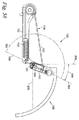
図1は、腕部支持外骨格(支援装置)100の実施例を示す。腕部支持外骨格100は、人の胴体202に結合されるように構成された肩部基部102を備える。本発明のいくつかの実施例において、肩部基部102は、人(ユーザ)200の後方に実施的に位置付けられる。腕部支持外骨格100は、肩部基部102に連結された少なくとも1つの腕部リンク機構104をさらに備える。腕部リンク機構104は、少なくとも近位リンク150および遠位リンク152を備え、これらは第1回転軸154に沿って相互に対して回転可能である。本発明のいくつかの実施例において、第1回転軸154は、人200が直立しているときに重力線208に直交している。用語「重力線」は、重力が作用する方向を意味すると理解されるべきである。第1ジョイント151は、遠位リンク152が近位リンク150に対して回転するヒンジとして働く。腕部支持外骨格100は、人の上腕204を腕部リンク機構104の遠位リンク152に連結する少なくとも1つの腕部連結器106をさらに備える。腕部連結器106は図2に示される。腕部支持外骨格100は、近位リンク150と遠位リンク152との間にトルク280を生成するように構成された、少なくとも1つのトルク発生器108をさらに備える。腕部リンク機構104の拡大図が図3に示されている。図1および図3においてトルク280は、近位リンク150から遠位リンク152に印加されるトルクを示す。図4に示すように、第1角度193は、近位リンク150と遠位リンク152との間の角度を表す。第1角度193がトグル角度195よりも小さい場合、図4に示すように、トルク発生器108は、近位リンク150に対して遠位リンク152を屈曲させる傾向を有するトルク280を生成する。「トグル角度」という用語は、近位リンク150と遠位リンク152とが同一線上にある第1位置(例えば、腕部が持ち上げられる)と、近位リンク150と遠位リンク152が同一線上になる第2位置(例えば、腕部が下がる)との間の角度を意味する。用語「屈曲」は、第1角度193の減少をもたらす遠位リンク152の動きを意味すると理解されるべきであり、本明細書で使用される用語「伸長」は、第1角度193の増加をもたらす遠位リンク152の動きを意味すると理解されるべきである。トルク280は、腕部連結器106によって上腕204に支持力212(図2および図4に示す)を生成する。これにより、人の上腕204を持ち上げるのに必要な人間の肩の力およびトルクが低減され、肩部基部102上の反作用力214および反作用トルク215を印加する。
FIG. 1 shows an embodiment of an arm supporting exoskeleton (assisting device) 100. The
角度193が図5に示すようにトグル角度195より大きい場合、トルク発生器108は、近位リンク150と遠位リンク152との間に実質的に小さなトルクを供給する。「実質的に小さなトルク」という用語は、人の上腕204の実質的な抑制または不快感を引き起こすことのないトルクの値と理解すべきである。これにより、人200は上腕204を自由に動かすことができる。図5に示す例では、ユーザの上腕204が下降すると、遠位リンク152の位置が近位リンク150と同一線上の位置を通過し、トルク発生器は近位リンク150と遠位リンク152との間に実質的に小さなトルクを供給する。ユーザはこの下降位置で上腕204を容易に操作することができる。
If
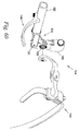
図6は、肩部基部102に結合された2つの腕部リンク機構104を含む腕部支持外骨格100の別の実施例を示し、各々は少なくとも1つのトルク発生器108および少なくとも1つの腕部連結器106を含む。本発明のいくつかの実施例において、遠位リンク152は、人の上腕204と実質的に平行のままであるように動く。
FIG. 6 shows another embodiment of an
図6に示すように、本発明のいくつかの実施例において、外骨支持外骨格100の肩部基部102は、腕部リンク機構104に結合された荷重担持構造112と、肩部基部102を人の胴体202に取り付ける連結機構114とを備える。荷重担持構造112は、腕部リンク機構104からの反作用力214および反作用トルク215を支持する。図10から図13に示す本発明のいくつかの実施例において、反作用力214および反作用トルク215が人200に伝達する。図65に示されているように、反作用力214および反作用トルク215は、支持面(例えば、地面310)に伝達される。荷重担持構造112および連結機構114の様々な実施例を以下で説明する。
As shown in FIG. 6, in some embodiments of the present invention, the
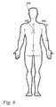
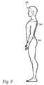
図7、図8、および図9は、ここでは、荷重担持構造112の説明において使用される様々な寸法を説明するために提示される。図7は、腰幅234、肩幅236、および人の正面平面250と含む、人200の正面図を示し、図8は、胴体高さ232および上腕長さ242を含む人200の背面図を示す。図9は、腰深さ238および肩深さ240を含む人200の側面図を示す。
7, 8, and 9 are presented here to illustrate the various dimensions used in the description of the
図10〜図13は荷重担持構造の種々の実施例を示す。図10に示すように、実施例においては、荷重担持構造112は、腕部リンク機構104(図示せず)からの反作用力214およびトルク215を支持する背部フレーム130を有する。腰部装填ベルト131は、反作用力214および反作用トルク215の少なくとも一部を人の腰部220(図14に示す)に伝達し、腰部反作用力221をもたらす。背部フレーム130は、肩部反作用力225によって示されるように、反作用力214の少なくとも一部を人の肩部224(図14に示す)にも伝達する。背部フレーム130は、カスタムメイドであってよく、または、人の胴体高さ232、腰幅234、肩幅236、腰深さ238、肩深さ240、またはそれらの任意の組み合わせに適合するように増分的に寸法調整されてよい。本発明のいくつかの実施例において、腰部装填ベルト131および背部フレーム130は、1つのアイテムとして構成されている。
10 to 13 show various embodiments of the load carrying structure. As shown in FIG. 10, in an embodiment, the
図11は、腕部リンク機構104(図示せず)に連結された上側フレーム136と、上側フレーム136に並進可能に連結された下側フレーム138とを含む荷重担持構造112の他の実施例を示し、望ましい胴体高さ調整233を提供する人の胴体の高さ232のための下側フレーム138を含む。下側フレーム138は、腰部装填ベルト131に連結されるか、またはその一部である。腕部リンク機構104からの反作用力214は、上側フレーム136によって支持され、上側フレーム136は、肩部反作用力225によって示されるように、反作用力214の少なくとも一部を人の肩部224に伝達することができる。上側フレーム136は、人の肩の幅236および肩の深さ240に適合するように漸増的にサイズ付けされてもよい。下側フレーム138は、カスタムメイドであってもよいし、人の腰幅234および腰深さ238を含む。
FIG. 11 illustrates another embodiment of the
図12は、背部フレーム130が、上側フレーム136を下側フレーム138に接続する脊柱フレーム134をさらに含む荷重担持構造112のさらなる実施例を示す。脊柱フレーム134は、下側フレーム138にその下端部において回転可能に結合される人の正面平面250における下側フレーム138に対する脊柱フレーム134の回転を可能にする。中外側屈曲動作260は、脊柱フレーム134と下側フレーム138との間の動きの方向を示す。脊柱フレーム134は、脊柱フレーム軸に沿って脊柱の捻れ動作262は、脊柱フレーム134と上側フレーム136との間の動きの方向を示す。また、上側フレーム136は、脊柱フレーム軸135に沿って脊柱フレーム134に対して並進して、人の胴高232の胴体高さ調整233を提供する。上側フレーム136と脊柱フレーム134との間の脊柱捻れ動作262と、下側フレーム138と脊柱フレーム134との間の内外屈曲動作260との自由度の程度によって、上側フレーム136が人の胸部222(図14に示されている)と実質的に一体的に移動でき、下側フレーム138が、人の腰部220と実質的に一体的に移動できる。
FIG. 12 illustrates a further embodiment of the
図13は、下側フレーム138が下側中央バー144および2つの下側コーナーバー140をさらに備え、各下側コーナーバー140は、下側中央バー144上の種々の位置で下側中央バー144に結合でき、これによって、庶務の腰部幅調整を実現して人の腰幅234に適合させる。下側フレーム138は、当該下側フレーム138上の種々の位置で下側フレーム138に結合されてよい2つの下側サイドブラケット149をさらに有してよく、人の腰深さ238に対応するために望ましい腰深さ調整239を実現する。上側フレーム136は、上側中央バー142および2つの上側コーナーバー146をさらに有し、各上側コーナーバー146は、当該上側中央バー142上の種々の位置で当該上側中央バー142に結合でき、もって、人の肩幅236に適合するように所望の肩幅調整237を実現する。上側フレーム136は、また、2つの上側サイドブラケットを有し、各上側サイドブラケット148は、当該上側フレーム136上の種々の位置で上側フレーム136に結合でき、もって、人の肩深さ240に対応するために望ましい肩深さ調整241を提供することができる。上側フレーム136は、また、当該上側フレーム136に曲線を渡しかけるハンモック128を有し、もって、人の肩部224(図14に示す)にそれぞれの肩部反作用力225をより均一に分配する。上側サイドブラケット、上側コーナーバー、下側サイドブラケット、および下側コーナーバーの調整には、プランジャピン、スクリュー、クランプ、摩擦ロック、ラックアンドピニオン、またはそれらの任意の組合せの使用が含まれて良い。
FIG. 13 shows that the
図14〜図22は、連結機構114が、ベルト取付点115において荷重担持構造112に取り付けられ、人の腰部220を少なくとも部分的に取り囲むベルト116を含む、本発明の様々な実施例を示す。ベルト116は人の腰部220と一体的に移動できる。いくつかの実施例において、ベルト116は、人の腰部220にしっかりと取り付けられるように長さを変えることができる。
14-22 illustrate various embodiments of the present invention in which the
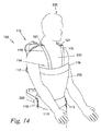
図14、15および16は、肩部基部102の様々な実施例を示す。図14は、人200を伴う肩部基部102の正面斜視図を示す。図15は、人200を伴わない肩部基部102の背面図を示す。図16は、人200を伴わない肩部基部102の背面斜視図を示す。この実施例において、連結機構114は、胸部ストラップ118を有する。胸部ストラップ118は、人の胸部222を少なくとも部分的に取り囲む。胸部ストラップ118は、ほぼ、人の胸部222のレベルで背中中央取付点117において荷重担持構造112に実装される。いくつかの実施例において、連結機構114は、少なくとも1つのアンカーストラップ119を含み、当該アンカーストラップ119は、その第1端部で、腹側取付点121において荷重担持構造112に取り付けられ、第2端部で胸部ストラップ118に取り付けられる。胸部ストラップ118およびアンカーストラップ119は、人の胸部222と一体的に動く。いくつかの実施例において、胸部ストラップ118およびアンカーストラップ119は、人の胸部222に確実に取り付けることができるように長さを変えることができる。いくつかの実施例において、胸部ストラップ118は堅固であり、アンカーストラップ119を締め付けることによるたわみを防止する。
FIGS. 14, 15 and 16 show various embodiments of the
図17、図18および図19は、肩部基部102の様々な実施例を示す。図17は、人200を伴う肩部基部102の正面斜視図を示す。図18は、人200を伴わない肩部基部102の背面図を示す。図19は、人200を伴わない肩部基部102の背面斜視図を示す。この実施例において、連結機構114は、少なくとも2つの肩部ストラップ120を含む。2つの肩部ストラップ120は、人の肩部224を少なくとも部分的に取り囲む。各肩部ストラップ120は、第1端部において、それぞれの上方腹側取付点121で荷重担持構造112に実装され、第2端部において、下方背側取付点123で荷重担持構造112に実装される。いくつかの実施例において、胸骨ストラップ122は、その第1端で1つの肩部ストラップ120に結合し、第2端で、もう1つの肩部ストラップ120に結合する。肩部ストラップ120および胸骨ストラップ122は、人の胸部222と一体的に動く。いくつかの実施例において、肩部ストラップ120および胸骨ストラップ122は、人の胸部222に確実に取り付けることができるように長さを変えることができる。いくつかの実施例において、肩部ストラップ120は、その第1端部において、上方腹側取付点121で荷重担持構造112に実装され、その第2端部において、背中中央取付点117において荷重担持構造112に実装される。
17, 18, and 19 illustrate various embodiments of the
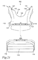
図20、21および22は、肩部基部102の様々な実施例を示す。図20は、人200を伴う肩部基部102の正面斜視図を示す。図21は、人200を伴わない肩部基部102の背面図を示す。図22は、人200を伴わない肩部基部102の背面斜視図を示す。この実施例において、連結機構114は、人の胸部222にしっかりと取り付けられるベスト124を含む。ベスト124は、人の胸部222と一体的に動くことができる。いくつかの実施例において、ベスト124は、複数のベスト取付点125によって肩部基部102に連結される。いくつかの実施例において、ベスト取付点125は、胸部ストラップ118、アンカーストラップ119、肩部ストラップ120、胸骨ストラップ122、またはそれらの任意の組み合わせに取り付けられる。
20, 21, and 22 show various embodiments of the
図23〜図25は、肩部基部102の実施例を示し、これらの図において、連結機構114は、人200が着用している安全ハーネス126に少なくとも1つの安全ハーネス取付点127によって結合でき、この際、安全ハーネス126を修正する必要がない。図23および図24は、ベスト124が少なくとも1つの安全ハーネス取付点127を含む本発明の実施例を示す。安全ハーネス取付点127は、安全ハーネス126を変更することなくベスト124を安全ハーネス126に取り付けることを可能にする。安全ハーネス取付点127は、ベスト124の前面、肩部、または背面に位置付けられて良い。図23は、ベスト124の前部および肩部の安全ハーネス取付点127の正面斜視図を示す。図24は、ベスト124の背部および肩部に安全ハーネス取付点を含む、実施例(荷重支持構造なし)の背面拡大斜視図を示す。安全ハーネス取付点127は、ベルクロループ、ボタン付きフラップ、ストラップ、バックル、クリップ、クランプ、またはそれらの任意の組み合わせから形成されて良い。図25は、ベルト116が少なくとも1つの安全ハーネス取付点127を含む、本発明の実施例を示す。安全ハーネス取付点127は、安全ハーネス126を修正することなく安全ハーネス126をベルト116に取り付けることを可能にする。いくつかの実施例において、安全ハーネス取付点127はベルト116の側部に位置付けられる。安全ハーネス取付点127は、アタッチメントの側に位置する点127ベルクロループ、ボタン付きフラップ、ストラップ、バックル、クリップ、クランプ、またはこれらの任意の組み合わせによって形成されて良い。
FIGS. 23-25 illustrate embodiments of the
図26は、腕部リンク機構104の拡大図を示す。この実施例において、第1ジョイント151の第1回転軸154は、人の肩関節218をほぼ通過する。図27は、この実施例の背面図を示し、腕部支持外骨格100は、2つの腕部リンク機構104とを含む。
FIG. 26 is an enlarged view of the
図28および図29は、腕部リンク機構104が少なくとも1つの水平回転ジョイント156を含む、腕部支持外骨格100の別の実施例を示す。水平回転ジョイント156によって、近位リンク150が、肩部基部102に対して第2回転軸155の周りに回転できる。第2回転軸155は、第1回転軸154と実質的に直交している。図29は、当該腕部リンク機構104の背面図を示し、ここでは、第2回転軸155が人間の肩関節218を実質的に通過するようになっている。
FIGS. 28 and 29 illustrate another embodiment of the
図30および図31は、肩部基部102に結合された少なくとも1つの肩部ブラケット153を含む腕部支持外骨格100の実施例を示す。肩部ブラケット153によって、腕部リンク機構104と肩部基部102との間の迅速な接続および取り外しが容易になる。図30は、腕部リンク機構104を肩部基部102に連結する肩部ブラケット153を示す。図31は、腕部リンク機構104を肩部基部102から取り外すことを可能にする肩部ブラケット153を示す。
FIGS. 30 and 31 show an example of an
図32は、肩部基部102に連結された少なくとも1つの肩部ブラケット153を含む腕部支持外骨格100の別の実施例を示す。肩部ブラケット153は、肩部基部102を腕部リンク機構104に複数の位置で連結して所望の肩幅調整237を実現して人の肩幅236に適合化させ、これは図7を参照されたい。図示しない別の実施例において、肩部ブラケット153は、人の肩深さ240に適合するように所望の肩部深さ調整241を提供するために、複数の位置で腕部リンク機構104に結合することができる。
FIG. 32 illustrates another embodiment of the
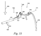
図33は腕部支持外骨格100の他の実施例を示しており、この図において、肩部基部102は少なくとも1つの肩部ブラケット153を有する。肩部ブラケット153は、肩甲骨回転軸171に沿って腕部リンク機構104に回転可能に連結されており、肩甲骨回転軸171は、人200(図示せず)が直立しているときに重力線208に実質的に直交する。
FIG. 33 shows another embodiment of the
図34〜図36は、肩部基部102が肩部ブラケット153に結合された腕部支持外骨格100の別の実施例を示す。肩部ブラケット153は、腕部リンク機構104に連結する。肩部ブラケット153は、当該肩部ブラケット153が肩部基部102(図34には示されていない格納ジョイント158)に対して回転する。肩部ブラケット153が格納ジョイント158の周りを回転すると、腕部リンク機構104を、人200の実質的に後方に配置することができる。肩部ブラケット153は、腕部リンク機構104を所望の向きに保つために格納ジョイント158の周りに静止して保持することができる。図34は、腕部支持外骨格100を着用している人200を示し、この図では、腕部リンク機構104が人の作業空間230から実質的に外れた格納位置にある。「人の作業空間」という用語は、一般的な職場作業中に利用することができる人の上腕204の運動範囲を意味すると理解すべきである。図35は、作業位置にある肩部ブラケット153の斜視図を示す。作業位置において、腕部リンク機構104は、人の上腕204(図示せず)を支持するように配置される。図36は、格納位置にある肩部ブラケット153の斜視図を示し、ここでは、腕部リンク機構104が実質的に人200(図示せず)の後ろに位置付けられる。格納位置において、遠位リンク152は、第1回転軸154の周りに作用するトルク発生器108のために、近位リンク150に対して完全に撓んだままである。これは、腕部リンク機構104を人の作業空間230からさらに保護する働きをする。腕部リンク機構104と肩部基部102との間の距離を利用して、腕部リンク機構104を人の作業空間230の外に保持することができる。
34-36 show another embodiment of the
図37〜図41は、腕部支持外骨格100の実施例を示しており、ここでは、腕部連結器106が、さらに、遠位リンク152に結合された荷重担持連結器160を有し、人の上腕204(図1に示す)に上向きの支持力212を加えることができる。いくつかの実施例において、荷重担持連結器160は、遠位リンク152に腕部連結器106を取り付ける遠位リンクアタッチメント167と、人の上腕204(図1に示す)を部分的に取り囲む少なくとも1つの腕部カフス部168とを備える。
FIGS. 37-41 show an embodiment of the
図37は、腕部連結器106がさらに腕部連結機構162を有する腕部支持外骨格100の実施例を示す。腕部連結機構162は、腕部連結器106を人の上腕204(図2に示す)に連結することが可能である。腕部連結機構162は、剛性、半剛性、または従順な材料からなる群から選択される要素または要素の組合せを有して良く、これは、腕部連結器106からの人の上腕204(図1に示す)の分離を防止する。
FIG. 37 shows an embodiment of the
図38は、荷重担持連結器160が腕部回転ジョイント164を含む腕部連結器106の実施例を示す。腕部回転ジョイント164によって、腕部カフス部168は、第1回転軸154と実質的に平行な腕部カフス部回転軸165に沿って、遠位リンク152に対して回転できる。腕部回転ジョイント164によって、腕部カフス部168が人の上腕204(図1に示す)と最大限の接触を実現し、または、遠位リンク152と人の上腕204との間の動きの不一致を補償できる。
FIG. 38 illustrates an embodiment of the
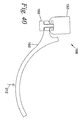
図39は、腕部連結器106の実施例を示しており、ここでは、腕部連結器106の位置を遠位リンク152に対して調整することができる。本発明のいくつかの実施例において、荷重担持連結器160は、並進ジョイント166において遠位リンク152に関して並進することができ、腕部リンク機構104の腕部長さ調整243を可能にして、人の上腕長さ242(図7参照)に適合できるようにし、または遠位リンク152と人の上腕204(図1に示す)との間の動きの不一致を補償することができる。図40は、遠位リンク152が荷重担持連結器160と噛合するt−溝を含む並進ジョイント166の別の実施例を示す。荷重担持連結器160は、遠位リンク152に対して荷重担持連結器160の位置を固定するロックピン169を含む。
FIG. 39 shows an embodiment of the
図41は、荷重担持連結器160が内外回転ジョイント172を用いて人の上腕204(図1に示す)の内外回転を可能にする、腕部連結器106の実施例を示す。内外回転ジョイント172は、遠位リンクアタッチメント167および腕部カフス部168の間に位置決めされる。内外回転ジョイント172は、内外回転軸173の周りを回転する。図示されていない別の実施例において、腕部カフス部168に載置されている人の上腕204との摺動接触によって、内外回転軸173を中心とした回転が可能になる。
FIG. 41 shows an example of an
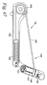
図42〜図46は、トルク発生器108が引張力発生器178を含む、外骨支持外骨格100の様々な実施例を示す。図42に示す引張力発生器178は、その第1引張端部176から近位リンク150に連結され、引張力発生器178の引張力は、第1回転ジョイント151を中心として近位リンク150に対して遠位リンク152を屈曲させるためのトルク280を付与する。トルク発生器108のいくつかの実施例において、引張力発生器178はコイルバネ要素180を有する。トルク発生器108のいくつかの実施例において、引張力発生器178は、コイルバネ要素180を近位リンク150に連結する線条要素182を備える。線条要素182は、ワイヤロープ、ロープ、ケーブル、ツイン、ストラップ、チェーン、またはそれらの任意の組み合わせからなるグループからセンタされた要素または要素の組み合わせを有する。トルク発生器108のいくつかの実施例において、線条要素182は、線条要素182が近位リンク150に結合される前に遠位リンク152に結合されたプーリ183を少なくとも部分的に取り囲む。いくつかの実施例において、プーリ183は、遠位リンク152に対して回転しない。実施例のプーリ183は、遠位リンク152に組み込まれた曲面である。図42は、コイルバネ要素180が伸長バネであるトルク発生器108の実施例を示す。コイルバネ要素180は、接合部179で線条要素182に結合され、第2引張端部177で遠位リンク152に結合される。
FIGS. 42-46 illustrate various embodiments of the
図43は、トルク発生器108の概略模式図を示す。引張力発生器178は、第1距離272で近位リンク150に結合される。引張力発生器178は、遠位リンクの周りに第2距離270で作用する。引張力発生器有効長276は、近位リンク150に沿った第1距離272と、遠位リンク152に沿った第2距離270との間の距離である。引張力発生器の元の長さは、第1角度193のゼロ値に対応する引張力発生器有効長276である。引張力は、第1角度193の所与の値に対して、バネ定数、バネ予荷重、引張力発生器の元の長さ、および引張力発生器有効長276の関数である。トルク280は、遠位リンクを肩部基部102に対して撓ませる。
FIG. 43 shows a schematic diagram of the
図44〜図46は、トルク発生器108の様々な実施例を示しており、張力発生器178は、コイルバネ要素180と線条要素182とを含む。線条要素182は、遠位リンク152に結合されたプーリ183を少なくとも部分的に取り囲んでいる。図44は、コイルバネ要素180が、図42に示されたものとは異なる向きの伸張バネであるトルク発生器108の実施例である。コイルバネ要素180は、接合部179で線条要素182に結合され、第2引張端部177で遠位リンク152に結合される。いくつかの実施例において、線条要素182は、近位リンク150に取り付ける前に遠位リンク152に取り付けられたプーリ183の周りに少なくとも部分的に巻き付いている。図45は、コイルバネ要素180が圧縮バネであるトルク発生器108の実施例を示す。いくつかの実施例において、線条要素182は、遠位リンク152に取り付けられたプーリ183の周りを少なくとも部分的に包み込んでから、近位リンク150に取り付ける前に、遠位リンク152に連結される。図46は、コイルバネ要素180が、図45に示されたものとは異なる向きの圧縮ばねであるトルク発生器108の実施例を示す。コイルバネ要素180は、接合部179で線条要素182に結合され、第2引張力端部177で遠位リンク152に連結される。いくつかの実施例において、線条要素182は、近位リンク150に取り付ける前に遠位リンク152に取り付けられたプーリ183の周りに少なくとも部分的に巻き付けられる。すべての実施例において、コイルバネ要素180の代わりに、気体バネ、空気バネ、エラストマー、または同様の挙動を示す任意の組み合わせを利用することができることに留意されたい。
FIGS. 44-46 illustrate various embodiments of the
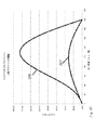
図47および図48は、近位リンク150が張力発生器178に結合された上側ブラケット188を備えるトルク発生器108の実施例を示す。上側ブラケット188の位置は、近位リンク150に沿って調整されて引張力発生器178により付与されるトルク280を調整できる。上側ブラケット188の位置は図43の模式図において第1距離272に対応する。いくつかの実施例において、上側ブラケット188の位置は、上側ブラケットネジ187によって近位リンク150に対して調整され、上側ブラケット188は上側ブラケットネジ187と噛み合うネジ溝付き機構を組み込んでいる。上側ブラケットネジ187を旋回させることにより、上側ブラケット188の位置は、近位リンク150に沿って調整される。一般に、上側ブラケット188が、第1ジョイント151から遠いほど、トルク280は大きくなる。図47は、第1ジョイント151に対して伸長位置にある上側ブラケット188を示し、これが大きな第1距離272をもたらす(図43参照)。図48は、上側ブラケット188を第1ジョイント151に対して格納された位置にある上側ブラケット188を示し、これは、小さな第1距離272(図42参照)をもたらす。図49は、図47および図48で説明した上側ブラケット188の2つの位置に対する第1角度193の関数として、トルク発生器108によって生成されたトルク280の2つのプロットを示す。図47に示す構成のトルクプロファイルは、トルクプロファイル288で表され、図48に示す構成のトルクプロファイルは、トルクプロファイル287によって表される。トルクプロファイル288は、トルクプロファイル287と比較してより大きな振幅を有することが分かる。
FIGS. 47 and 48 show an embodiment of the
図50および図51は、遠位リンク152が、張力発生器178に結合された下側ブラケット190を有する、トルク発生器108の実施例を示す。下側ブラケット190の位置は、遠位リンク152に沿って調整され、引張力発生器178により付与されるトルク280を調整できる。下側ブラケット190の位置は引張力発生器178の前置負荷に対応する。いくつかの実施例において、下側ブラケット190の位置は、下側ブラケットネジ189によって遠位リンク152に対して調整され、下側ブラケットは、下側ブラケットネジ189と噛み合うネジ溝付き機構を組み込んでいる。下側ブラケットネジ189を旋回させることにより、下側ブラケット190の位置は、遠位リンク152に沿って調整される。一般に、下側ブラケット190が第1ジョイント151から遠くなるほど、前置負荷が小さくなる。図50は、第1ジョイント151に対して長めの位置にある下側ブラケット190を示し、これは、引張力発生器178の小さな前置負荷をもたらす。図51は、第1ジョイント151に対して短めの位置にある下側ブラケット190を示しており、これは、引張力発生器178の大きな前置負荷をもたらす。図52は、図50および図51で説明した下側ブラケット190の2つの位置に対する第1角度193の関数として、トルク発生器108によって生成されるトルク280の2つのプロットを示す。図50に示す構成のトルクプロファイルは、トルクプロファイル290によって表され、図51に示す構成のトルクプロファイルは、トルクプロファイル289によって表される。短めの下側ブラケットトルクプロファイル289は、長めの下側ブラケットトルクプロファイル290と比較して、より大きな振幅を有する。
FIGS. 50 and 51 show an example of a
図53〜図55は、第1角度193がトグル角度195より大きい場合に、引張力発生器178によって付与されるトルク280が自動的に実質的に小さくとどまるという、本発明の重要な特徴を示す。すなわち、ユーザが、当該ユーザの腕部を、第1角度193がトグル角度195以上でない第1位置から、第1角度193がトグル角度195より大きい第2位置へと動かすときに、引張力発生器178は、第1トルクが引張力発生器178によって付与される第1トルクモード(腕部の第1位置)から、引張力発生器178によって実質的に小さなトルクしか付与されない第2トルクモード(腕部の第2位置)へと自動的に遷移する。同様に、ユーザが当該ユーザの腕部を第2位置から第1位置に戻すと、引張力発生器179は第2トルクモードから第1トルクモードへと自動的に遷移する。
FIGS. 53-55 illustrate an important feature of the present invention that when the
図53は、第1角度193が180度よりも大きく、腕部リンク機構104が、実質的に第1ジョイント151に位置付けられる突起186を有する構成を示す。第1角度193がトグル角度195以上になると、突起186が、引張力発生器178(図53に示すような力発生器178の線条要素182)を、第1ジョイント152の周りに実質的に中心づけられる位置に拘束する。引張力発生器178を拘束することによって、突起186は、引張力発生器178が第1ジョイント151を越えて通り過ぎていくのを阻止する。トルク280は、実質的にゼロのままであり、これは、拘束された引張力発生器178が実質的に第1ジョイント151の周りに中央づけられるからである。トグル角度195よりも大きい第1角度193は、人200が上腕204を当該人の側部に休めようとし、または、ツールベルトからツールを取り出そうとする状況に相当する。この状況において、実質的に小さなトルクが必要となり、これが、人の上腕204の自由運動を可能にし、または、印加されたトルク280のインピーダンスなしで上腕204を休息させることを可能にする。これは、非作業姿勢の間に、人に大きな全体的な快適さを与える。図54は、突起186が、第1ジョイント151を形成する第1ジョイントピン184によって形成される、本発明の実施例を示す。図55は、突起186が近位リンク150の一部である本発明の実施例を示す。
FIG. 53 shows a configuration in which the
図56は、突起186のない場合に、トルク発生器108によって生成されるトルク280の第1角度193の関数としてのグラフを示す。トグル角度195において、トルク280は負になる。トルク280の負の値は、人の上腕204の動きを妨げ、または人200の快適性を低下させる可能性がある。図57は、突起186が形成されたときにトルク発生器108によって生成されるトルク280の第1角度193の関数としてのグラフを示す。第1角度193がトグル角度195以上になると、突起186が引張力発生器178を拘束し、トルク280が実質的に小さいままであることが保証される(図53参照)。トグル角度195を過ぎると、トルク280は実質的にゼロになり、第1角度193の残りの角度において中立ゾーン197を形成する。中立ゾーン197は、人の上腕204が、トグル角度195より大きい第1角度193内において実質的にゼロの印加トルク280で移動することを可能にする。中立ゾーン197は、人200が上腕を中立位置に快適に置くことを可能にするか、またはポケットまたは工具ベルトに到達するような二次的作業を実施することを可能にする。
FIG. 56 shows a graph of the
図58および図59は、近位リンク150の向きを調節し、肩部基部102に対して所定の位置に保持することができる、腕部支持外骨格100の実施例を示す。近位リンクオフセット位置191は、人200が直立しているときに、肩部基部102に固定された近位リンク150の重力線208に対する方位として定義される。近位リンクオフセット位置191は、実質的に第1ジョイント151の平面内で回転するオフセット調整ジョイント159で調整される。トグル位置194は、第1ジョイント角度193がトグル角度195に等しくなったときの遠位リンク152の位置を表す。近位リンクオフセット位置191を調整することによって、トグル位置194は肩部基部102に対して調整される。オフセット角度199は、人200が直立しているときの近位リンクオフセット位置191と重力線208との間の角度を表す。図58は、オフセット角度199が比較的小さい本発明の実施例を示す。図59は、オフセット角度199が増加した本発明の実施例を示す。図60は、オフセット調整ジョイント159を含む腕部リンク機構104の分解実施例を示す。オフセット調整ジョイント159によって、近位リンク150が肩部基部102に対して回転できる。オフセット調整ジョイント159によって、近位リンク150の肩部基部102に対する回転を特定位置においてロックできる。
58 and 59 illustrate an example of an arm-supporting
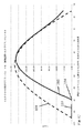
図61は、水平線209からの遠位リンク152の角度の関数としてトルク発生器108によって生成されたトルク280のグラフを示す。トルクプロファイル291は、オフセット角度199がゼロの場合の構成に対応する。トルクプロファイル292は、オフセット角度199が50度であるときの構成に対応し、近位リンク152の角度が水平線209の40度よりも高くない限り、上向きのトルクが人の腕を上方に押し上げないことを意味する。オフセット角度199を調整することによってトグル位置を動かすことができる。トルク発生器オフセット角度199は、水平線209に対して特定の角度でトグル位置194を位置決めするために調整することができる。トルク発生器オフセット角度199は、また、水平線209に対して所望の角度で特定のピーク位置を有するトルクプロファイルを生成する。突起186が存在するとき、トグル位置194を過ぎた近位リンク152の角度に対する両方の曲線に対して中立ゾーン197が形成される。より大きな範囲の中立ゾーン197が、人の上腕204の動きの範囲に対して生成される。
FIG. 61 shows a graph of the
いくつかの実施例において、下側ブラケット190、上側ブラケット188、および近位リンクオフセット位置191はすべて、トルク280のための所望の支持プロファイルを生成するように調整することができる。腕部重量トルクプロファイル198は、人の上腕204、前腕206、手207、およびツール308の重量に対抗するトルクとして定義される。図62は、トルク280のプロファイルを示しており、ここでは、当該トルク280のプロファイルは、実質的に水平209より上の角度における腕部重量トルクプロファイル198に合致して、ほぼ、腕部重量トルクプロファイル198を打ち消す。オーバヘッド溶接は、そのようなトルクを必要とするかもしれないユーザの活動の良い例である。遠位リンク152の絶対角度が水平線209から−60度を下回ると、トルク280のプロファイルは、トルクが実質的にゼロである中立ゾーン197に入る。トルク280のこのプロファイルは、腕部重量トルクプロファイルと比較して低減されたピーク振幅を有するトルク280を生成する下側ブラケット190の位置または上側ブラケット188の位置を用いて生成されてもよい。次に、オフセット角度199は、トルク280の支持プロファイルをシフトさせるように調整されて、所望の運動範囲に対して腕部重量トルクプロファイル198に密接に一致するようにすることができる。腕部重量トルクプロファイル198に一致させると、低減された振幅の支持トルク280は、トルク280が腕部重量トルクプロファイル198およびより大きな中立ゾーン197に一致する、より小さな角度範囲に対応する。
In some embodiments,
図63は、水平280より上のある角度で腕部重量トルクプロファイル198より大きい値を有するトルク280の別の支持プロファイルを示す。これは、人200が、上腕204、前腕206、手207、およびツール308の合計重量より大きな上方の力を印加する必要があるときに有益である。天井をドリル空けすることは、このようなトルクを必要とする可能性のあるユーザ活動の良い例である。遠位リンク152の絶対角度が水平線209から−40度以下になると、トルク280のプロファイルは、トルクが実質的にゼロである中立ゾーン197に入る。トルク280のこのプロファイルは、腕部重量トルクプロファイル198と比較して任意のピーク振幅を有するトルク280を生成する下側ブラケット190の位置または上側ブラケット188の位置を用いて生成することができる。オフセット角度199は、トルク280のプロファイルが所望の運動範囲に対する腕部重量トルクプロファイル198を超えるように当該トルク280のプロファイルを調整して遷移させて良い。腕部重量トルクプロファイル198に調整されると、低減された振幅の支持トルク280は、トルク280が腕部重量トルクプロファイル198およびより大きな中立ゾーン197を超えるより小さな角度範囲に対応する。
FIG. 63 shows another support profile for
図64は、トルク280の別の実現可能な支持プロファイルを示しており、これはすべての角度で腕部重量トルクプロファイル198と実質的に等しい値を有する。このようなトルクを必要とする可能性があるユーザ活動の一例として、全運動範囲にわたってツールを操作することが挙げられる。トルク280のこのプロファイルは、腕部重量トルクプロファイル198と比較して等しいピーク振幅を有するトルク280を生成する下側ブラケット190の位置190または上側ブラケット188の位置を用いて生成することができる。次に、オフセット角度199を調整して、トルク280のプロファイルのピークを腕部重量トルクプロファイル198に整合させて良い。水平からの偏差が−90°より下では、トルク280は、当該トルク280が実質的にゼロである中立ゾーン197(図示せず)に入る。すべての前進範囲の動きがサポートされている場合であっても、中立ゾーン197は、ユーザの手が後ろのポケットに達するときなど、人の腕204が人の胴体202の背後に負に伸びるとき、実質的にゼロのトルクを付与する。
FIG. 64 shows another possible support profile for
図65は、荷重担持構造112が、人200の実質的に背後に位置する背部フレーム130と、背部フレーム130に結合され、また、人の脚部228に結合される下肢外骨格304とを備える実施例を示す。背部フレーム130は、腕部リンク機構104から反作用力214および反作用トルク215の少なくとも一部を支持する。背部フレーム130は、反作用力214および反作用トルク215の少なくとも一部を下肢外骨格304に伝達する。下肢外骨格304は、反作用力214および反作用トルク215の少なくとも一部を地面310に伝達し、もって地面反作用力311が生じる。米国特許第8,894,592号、米国特許第8,070,700号、米国特許第8,945,028号、米国特許第8,057,410号、米国特許第7,947,004号は、本発明の側面に従って、腕部支持外骨格100に結合できる下肢外骨格のいくつかの例が記載されている。
FIG. 65 shows that the load-carrying
図66は、荷重担持構造112が、人200の実質的に背後に位置する背部フレーム130と、背部フレーム130に結合された外骨格302を支持する胴部とを有する実施例を示す。米国特許および特許出願公開第2015/0230964号、同第2014/0378882号、米国特許第9,308,112号および同第9,2022,956号は、本発明の側面に従って腕部支持外骨格100を支持する腕に結合することができる体幹支持外骨格のいくつかの例が記載されている。
以下、ここで説明した技術的特徴を非限定的に列挙する。
[技術的特徴1]
人体に結合されるように構成された腕部支持外骨格において、
人の胴体に結合されるように構成された肩部基部と、
前記肩部基部に連結される腕部リンク機構とを有し、
前記腕部リンク機構は、
前記人が直立しているときに、重力線と実質的に直交する第1回転軸に沿って回転ジョイントの周りに相互に回動するように構成された近位リンクおよび遠位リンクと、
前記人の上腕を前記遠位リンクに結合するように構成された少なくとも1つの腕部連結器と、
引張力発生器であって、当該引張力発生器の第1端部で前記近位リンクに連結され、前記引張力発生器の第2端部で前記遠位リンクに連結された前記引張力発生器と、
前記回転ジョイントに実質的に配置された突起とを有し、
前記遠位リンクがトグル角度を超えて延びるとき、前記突起は前記張力発生器を拘束し、前記張力発生器によって付与されるトルクは実質的に小さいままであり、
前記突起が前記張力発生器を拘束しないとき、前記トルクは、前記遠位リンクを前記近位リンクに対して撓ませる傾向があり、それによって前記人の前記上腕を引き上げるのに必要な前記人の肩の力およびトルクを低減することを特徴とする腕部支持外骨格。
[技術的特徴2]
人体に結合されるように構成された腕部支持外骨格において、
人の胴体に結合されるように構成された肩部基部と、
前記肩部基部に結合される腕部リンク機構とを有し、
前記腕部リンク機構は、
前記人が直立しているときに、重力線と実質的に直交する第1回転軸に沿って回転ジョイントの周りに相互に回動するように構成された近位リンクおよび遠位リンクと、
前記人の上腕を前記遠位リンクに結合するように構成された少なくとも1つの腕部連結器と、
引張力発生器であって当該引張力発生器の第1端部で前記近位リンクに結合され、前記引張力発生器の第2端部で前記遠位リンクに結合された前記引張力発生器とを有し、
前記腕部支持外骨格が前記人体に連結され、前記近位リンクと前記遠位リンクとの間の角度がトグル角度よりも小さいとき、前記トルクは、前記近位リンクに対して前記遠位リンクを撓ませる傾向があり、これによって前記人の上腕を持ち上げるために必要な前記人の肩部の力およびトルクを低減させ、前記肩部基部に反作用力およびトルクを加え、
前記近位リンクと前記遠位リンクとの間の前記角度が前記トグル角度より大きいとき、前記近位リンクと前記遠位リンクとの間に実質的に小さなトルクを付与し、前記人が前記人の前記上腕を自由に動かせるようにすることを特徴とする腕部支持外骨格。
[技術的特徴3]
人体に結合されるように構成された腕部支持外骨格において、
人の胴体に結合されるように構成された肩部基部と、
前記肩部基部に連結される腕部リンク機構とを有し、
前記腕部リンク機構は、
前記人が直立しているときに、重力線と実質的に直交する第1回転軸に沿って回転ジョイントの周りに相互に回動するように構成された近位リンクおよび遠位リンクと、
前記人の上腕を前記遠位リンクに結合するように適合された少なくとも1つの腕部連結器と、
前記近位リンクと前記遠位リンクとの間にトルクを生成するように構成された少なくとも1つのトルク発生器とを有し、
前記腕部支持外骨格が前記人体に連結され、前記近位リンクと前記遠位リンクとの間の角度がトグル角度よりも小さいとき、前記トルクは、前記近位リンクに対して前記遠位リンクを撓ませる傾向があり、これによって前記人の上腕を持ち上げるために必要な前記人の肩部の力およびトルクを低減させ、前記肩部基部に反作用力およびトルクを加え、
前記近位リンクと前記遠位リンクとの間の前記角度が前記トグル角度より大きいとき、前記近位リンクと前記遠位リンクとの間に実質的に小さなトルクを付与し、前記人が前記人の前記上腕を自由に動かせるようにすることを特徴とする腕部支持外骨格。
[技術的特徴4]
技術的特徴3に記載の腕部支持外骨格において、
前記肩部基部は、
前記肩部基部上の前記反作用力およびトルクを支持する、前記腕部リンク機構に結合された荷重担持構造と、
前記肩部基部が前記人の前記胴体胴と一体的に動くように、前記負荷暗示構造を前記人の前記胴体に結合するように構成された連結機構とを有する、前記腕部支持外骨格。
[技術的特徴5]
技術的特徴4に記載の腕部支持外骨格において、
前記荷重担持構造は、
前記腕部リンク機構に連結され、前記腕部リンク機構からの前記反作用力およびトルクの少なくとも一部を支持する背部フレームと、
前記背部フレームに結合された少なくとも1つの腰部装填ベルトであって、前前記背部から前記反力およびトルクの少なくとも一部を前記人の腰部に伝達する、前記腰部装填ベルトとを有する、前記腕部支持外骨格。
[技術的特徴6]
技術的特徴4に記載の腕部支持外骨格において、
前記荷重担持構造は、
前記人の背部の実質的に後方に位置付けられるように構成された背部フレームであって、前記腕部リンク機構に結合され、前記腕部リンク機構からの前記反作用力およびトルクの少なくとも一部を支持する、前記背部フレームと、
前記背部フレームおよび前記人の脚部に結合されるように構成された下肢外骨格であって、前記腕部リンク機構からの前記反作用力およびトルクの少なくとも一部を、前記人が直立している支持表面に伝達する、前記下肢外骨格とを有する、前記腕部支持外骨格。
[技術的特徴7]
技術的特徴5に記載の腕部支持外骨格において、
前記背部フレームは、
前記腕部リンク機構に結合された上側フレームと、
前記腰部装填ベルトに結合された下側フレームと、
脊柱フレームとを有し、
前記脊柱フレームは、当該脊柱フレームの上端で前記上側フレームに結合され、当該脊柱フレームの下端で前記下側フレームに回転可能に結合され、前記上側フレームが前記下側フレームに対して前記人の前面平面において回動可能である、前記腕部支持外骨格。
[技術的特徴8]
技術的特徴5に記載の腕部支持外骨格において、
前記背部フレームは、
前記腕部リンク機構に結合された上側フレームと、
前記腰部装填ベルトに結合された下側フレームと、
脊柱フレームとを有し、
前記脊柱フレームは、当該脊柱フレームの下端で前記下側フレームに結合され、当該脊柱フレームの上端で前記上側フレームに回転可能に結合され、前記上側フレームが前記下側フレームに対して前記脊柱フレームの主軸に沿って回動可能である、前記腕部支持外骨格。
[技術的特徴9]
技術的特徴4に記載の腕部支持外骨格において、
前記連結機構は、
前記人の胸部を少なくとも部分的に包囲するように構成され、前記人の実質的に後方の位置において前記上側フレームに結合される胸部ストラップと、
前記胸部ストラップを前記人の対応する肩部を越えて前記上側フレームに結合するように適合化された第1および第2のアンカーストラップとを有し、
前記胸部ストラップおよび前記第1および第2のアンカーストラップを前記上側フレームに結合することによって前記上側フレームが前記人の前記胸部および前記化t部と一体的に動くことができる、前記腕部支持外骨格。
[技術的特徴10]
技術的特徴4に記載の腕部支持外骨格において、
前記連結機構は、前記肩部基部を前記人に連結させるように適合化された第1および第2の肩部ストラップを有する、前記腕部支持外骨格。
[技術的特徴11]
技術的特徴3に記載の腕部支持外骨格において、
前記トルク発生器は、引張力発生器を有し、当該引張力発生器は、当該引張力発生器の第1端部からの前記近位リンクに結合され、当該引張力発生器の第2端部からの前記遠位リンクに結合され、前記引張力発生器における引張力が、前記遠位リンクを前記近位リンクに対して屈曲させるトルクを形成する、前記腕部支持外骨格。
[技術的特徴12]
技術的特徴11に記載の腕部支持外骨格において、
前記回転ジョイントに実質的に位置付けられる突起をさらに有し、
前記遠位リンクが前記トグル角度を越えて伸びるときに、前記突起が、前記引張力発生器を拘束して、前記引張力発生器による付与されるトルクが実質的に小さなままに維持されるようにする、前記腕部支持外骨格。
[技術的特徴13]
技術的特徴11に記載の腕部支持外骨格において、
前記近位リンクの配位が、前記肩部基部に対して、前記第1回転軸に実質的に平行な軸に沿って、調整され、その位置に維持でき、前記トグル角度の位置を前記肩部基部に対して調整できる、前記腕部支持外骨格。
[技術的特徴14]
技術的特徴11に記載の腕部支持外骨格において、
前記近位リンクは前記引張力発生器に結合された上側ブラケットを有し、前記上側ブラケットの位置が前記近位リンクに沿って調整可能であって前記引張力発生器により付与される前記トルクを調整する、前記腕部支持外骨格。
[技術的特徴15]
技術的特徴11に記載の腕部支持外骨格において、
前記遠位リンクは前記引張力発生器に結合された下側ブラケットを有し、前記下側ブラケットの位置が前記遠位リンクに沿って調整可能であって前記引張力発生器の前置荷重力を調整する、前記腕部支持外骨格。
[技術的特徴16]
技術的特徴3に記載の腕部支持外骨格において、
前記腕部リンク機構は、少なくとも1つの水平回転ジョイントを拘束し、前記水平回転ジョイントは、前記人の肩関節を実質的に通り抜ける、前記第1回転軸と実質的に直行する第2回転軸の周りに、前記近位リンクを、前記肩部基部に対して回動させることができる、前記腕部支持外骨格。
[技術的特徴17]
技術的特徴3に記載の腕部支持外骨格において、
前記肩部基部は、少なくとも1つの肩部ブラケットを有し、前記肩部ブラケットは、前記腕部リンク機構を前記肩部基部に迅速に着脱することができる、前記腕部支持外骨格。
[技術的特徴18]
技術的特徴3に記載の腕部支持外骨格において、
前記肩部基部は、少なくとも1つの肩部ブラケットを有し、前記肩部ブラケットは、前記腕部リンク機構の位置を前記肩部基部に対して調整できる態様で、前記腕部リンク機構を前記肩部基部に結合する、前記腕部支持外骨格。
[技術的特徴19]
技術的特徴3に記載の腕部支持外骨格において、
前記腕部リンク機構は、少なくとも1つの回転ジョイントを拘束し、前記回転ジョイントは、重力繊維実質的に著効する少なくとも1つの肩甲骨回転軸に沿って上記近位リンクを前記肩部基部に対して回動可能にする、前記腕部支持外骨格。
[技術的特徴20]
技術的特徴3に記載の腕部支持外骨格において、
前記肩部基部は、少なくとも1つの肩部ブラケットを有し、前記肩部ブラケットは、前記肩部基部に回転可能に結合され、前記腕部リンクに結合され、前記肩部ブラケット格納軸に沿って回転し、静止状態に維持可能であり、前記人の作業空間の実質的な外部である、前記人の後方に前記腕部リンク機構を収容できる、前記腕部支持外骨格。
FIG. 66 illustrates an embodiment in which the
Hereinafter, the technical features described here are listed in a non-limiting manner.
[Technical features 1]
In an arm supporting exoskeleton configured to be coupled to a human body,
A shoulder base configured to be coupled to a human torso;
Having an arm link mechanism connected to the shoulder base,
The arm link mechanism,
A proximal link and a distal link configured to pivot relative to each other about a rotary joint along a first axis of rotation substantially orthogonal to the line of gravity when the person is upright;
At least one arm coupler configured to couple the upper arm of the person to the distal link;
A tension generator coupled to the proximal link at a first end of the tension generator and coupled to the distal link at a second end of the tension generator. Vessels,
A projection substantially disposed on the rotary joint,
When the distal link extends beyond the toggle angle, the protrusion restrains the tension generator and the torque provided by the tension generator remains substantially small;
When the protrusion does not restrain the tension generator, the torque tends to deflect the distal link relative to the proximal link, thereby increasing the person's upper arm needed to raise the person's upper arm. An arm supporting exoskeleton characterized by reducing shoulder force and torque.
[Technical features 2]
In an arm supporting exoskeleton configured to be coupled to a human body,
A shoulder base configured to be coupled to a human torso;
Having an arm link mechanism coupled to the shoulder base,
The arm link mechanism,
A proximal link and a distal link configured to pivot relative to each other about a rotary joint along a first axis of rotation substantially orthogonal to the line of gravity when the person is upright;
At least one arm coupler configured to couple the upper arm of the person to the distal link;
A tension generator coupled to the proximal link at a first end of the tension generator and coupled to the distal link at a second end of the tension generator. And
When the arm-supporting exoskeleton is connected to the human body and the angle between the proximal link and the distal link is less than a toggle angle, the torque is applied to the distal link relative to the proximal link. Tending to deflect, thereby reducing the person's shoulder force and torque required to lift the person's upper arm, applying a reaction force and torque to the shoulder base,
When the angle between the proximal link and the distal link is greater than the toggle angle, applying a substantially smaller torque between the proximal link and the distal link, wherein the person is An arm supporting exoskeleton, wherein the upper arm can be freely moved.
[Technical features 3]
In an arm supporting exoskeleton configured to be coupled to a human body,
A shoulder base configured to be coupled to a human torso;
Having an arm link mechanism connected to the shoulder base,
The arm link mechanism,
A proximal link and a distal link configured to pivot relative to each other about a rotary joint along a first axis of rotation substantially orthogonal to the line of gravity when the person is upright;
At least one arm coupler adapted to couple the upper arm of the person to the distal link;
At least one torque generator configured to generate torque between the proximal link and the distal link;
When the arm-supporting exoskeleton is connected to the human body and the angle between the proximal link and the distal link is less than a toggle angle, the torque is applied to the distal link relative to the proximal link. Tending to deflect, thereby reducing the person's shoulder force and torque required to lift the person's upper arm, applying a reaction force and torque to the shoulder base,
When the angle between the proximal link and the distal link is greater than the toggle angle, applying a substantially smaller torque between the proximal link and the distal link, wherein the person is An arm supporting exoskeleton, wherein the upper arm can be freely moved.
[Technical features 4]
In the arm supporting exoskeleton according to the technical feature 3,
The shoulder base,
A load bearing structure coupled to the arm linkage for supporting the reaction force and torque on the shoulder base;
A coupling mechanism configured to couple the load implied structure to the torso of the person such that the shoulder base moves integrally with the torso of the person.
[Technical features 5]
In the arm supporting exoskeleton according to the technical feature 4,
The load carrying structure,
A back frame coupled to the arm link mechanism and supporting at least a portion of the reaction force and torque from the arm link mechanism;
At least one waist loading belt coupled to the back frame, the waist loading belt transmitting at least a portion of the reaction force and torque from the front back to the waist of the person; Supporting exoskeleton.
[Technical features 6]
In the arm supporting exoskeleton according to the technical feature 4,
The load carrying structure,
A back frame configured to be positioned substantially behind the back of the person, the back frame coupled to the arm link mechanism and supporting at least a portion of the reaction force and torque from the arm link mechanism. The back frame;
A lower limb exoskeleton configured to be coupled to the back frame and the leg of the person, wherein the person is upright at least a portion of the reaction force and torque from the arm linkage. The arm support exoskeleton comprising: the lower limb exoskeleton communicating to a support surface.
[Technical features 7]
In the arm supporting exoskeleton according to the
The back frame,
An upper frame coupled to the arm link mechanism;
A lower frame coupled to the waist loading belt,
Having a spine frame,
The spine frame is coupled to the upper frame at an upper end of the spine frame, and is rotatably coupled to the lower frame at a lower end of the spine frame, wherein the upper frame is a front surface of the person with respect to the lower frame. The arm support exoskeleton, which is rotatable in a plane.
[Technical features 8]
In the arm supporting exoskeleton according to the
The back frame,
An upper frame coupled to the arm link mechanism;
A lower frame coupled to the waist loading belt,
Having a spine frame,
The spine frame is coupled to the lower frame at a lower end of the spine frame, and rotatably coupled to the upper frame at an upper end of the spine frame, wherein the upper frame is formed of the spine frame with respect to the lower frame. The arm-supporting exoskeleton, which is rotatable along a main axis.
[Technical features 9]
In the arm supporting exoskeleton according to the technical feature 4,
The connection mechanism,
A chest strap configured to at least partially surround the chest of the person and coupled to the upper frame in a position substantially behind the person;
First and second anchor straps adapted to couple the chest strap to the upper frame over a corresponding shoulder of the person;
Said arm support outside, wherein said chest frame and said first and second anchor straps are coupled to said upper frame so that said upper frame is able to move integrally with said chest and said t-section of said person. Skeleton.
[Technical features 10]
In the arm supporting exoskeleton according to the technical feature 4,
The arm support exoskeleton, wherein the coupling mechanism has first and second shoulder straps adapted to couple the shoulder base to the person.
[Technical features 11]
In the arm supporting exoskeleton according to the technical feature 3,
The torque generator includes a pull generator, the pull generator coupled to the proximal link from a first end of the pull generator, and a second end of the pull generator. The arm-supporting exoskeleton coupled to the distal link from a portion, wherein a pulling force at the pulling force generator creates a torque that causes the distal link to bend relative to the proximal link.
[Technical features 12]
In the arm supporting exoskeleton according to the technical feature 11,
Further comprising a protrusion substantially positioned on the rotary joint;
As the distal link extends beyond the toggle angle, the protrusion restrains the tension generator such that the applied torque by the tension generator remains substantially small. The arm-supporting exoskeleton.
[Technical features 13]
In the arm supporting exoskeleton according to the technical feature 11,
The configuration of the proximal link can be adjusted and maintained in position relative to the shoulder base along an axis substantially parallel to the first axis of rotation, and the position of the toggle angle can be adjusted to the shoulder base. Said arm support exoskeleton adjustable with respect to the base of the arm.
[Technical features 14]
In the arm supporting exoskeleton according to the technical feature 11,
The proximal link has an upper bracket coupled to the tension generator, and the position of the upper bracket is adjustable along the proximal link to reduce the torque applied by the tension generator. Adjusting said arm-supporting exoskeleton.
[Technical features 15]
In the arm supporting exoskeleton according to the technical feature 11,
The distal link has a lower bracket coupled to the tension generator, the position of the lower bracket being adjustable along the distal link, and the front load force of the tension generator being adjustable. Adjusting the arm support exoskeleton.
[Technical features 16]
In the arm supporting exoskeleton according to the technical feature 3,
The arm linkage constrains at least one horizontal rotation joint, the horizontal rotation joint having a second rotation axis substantially through the person's shoulder joint and substantially orthogonal to the first rotation axis. The arm support exoskeleton about which the proximal link can be pivoted relative to the shoulder base.
[Technical features 17]
In the arm supporting exoskeleton according to the technical feature 3,
The arm support exoskeleton, wherein the shoulder base has at least one shoulder bracket, wherein the shoulder bracket can quickly attach and detach the arm linkage to the shoulder base.
[Technical features 18]
In the arm supporting exoskeleton according to the technical feature 3,
The shoulder base has at least one shoulder bracket, and the shoulder bracket adjusts the position of the arm link mechanism relative to the shoulder base. Said arm support exoskeleton coupled to the base of the arm.
[Technical features 19]
In the arm supporting exoskeleton according to the technical feature 3,
The arm link mechanism constrains at least one revolute joint, the revolute joint moving the proximal link relative to the shoulder base along at least one scapula rotation axis where gravity fibers substantially effect. Said arm-supporting exoskeleton for pivoting.
[Technical features 20]
In the arm supporting exoskeleton according to the technical feature 3,
The shoulder base has at least one shoulder bracket, wherein the shoulder bracket is rotatably coupled to the shoulder base, coupled to the arm link, and along the shoulder bracket storage axis. The arm-supporting exoskeleton, which is rotatable and can be kept stationary, and is capable of accommodating the arm link mechanism behind the person, substantially outside the workspace of the person.
100 腕部支持外骨格
102 肩部基部
104 腕部リンク機構
106 腕部連結器
108 トルク発生器
112 荷重担持構造
114 連結機構
115 ベルト取付点
116 ベルト
117 背中中央取付点
118 胸部ストラップ
119 アンカーストラップ
120 肩部ストラップ
121 上方腹側取付点
122 胸骨ストラップ
123 下方背側取付点
124 ベスト
125 ベスト取付点
126 安全ハーネス
127 安全ハーネス取付点
128 ハンモック
130 背部フレーム
131 腰部装填ベルト
134 脊柱フレーム
135 脊柱フレーム軸
136 上側フレーム
138 下側フレーム
140 下側コーナーバー
142 上側中央バー
144 下側中央バー
146 上側コーナーバー
148 上側サイドブラケット
149 下側サイドブラケット
150 近位リンク
152 遠位リンク
153 肩部ブラケット
156 水平回転ジョイント
158 格納ジョイント
159 オフセット調整ジョイント
160 荷重担持連結器
162 腕部連結機構
164 腕部回転ジョイント
165 腕部カフス部回転軸
166 並進ジョイント
167 遠位リンクアタッチメント
168 腕部カフス部
169 ロックピン
171 肩甲骨回転軸
172 内外回転ジョイント
173 内外回転軸
178 引張力発生器
179 接合部
180 コイルバネ要素
182 線条要素
183 プーリ
186 突起
187 上側ブラケットネジ
188 上側ブラケット
189 下側ブラケットネジ
190 下側ブラケット
191 近位リンクオフセット位置
193 第1角度
194 トグル位置
195 トグル角度
197 中立ゾーン
198 腕部重量トルクプロファイル
199 オフセット角度
200 人
202 胴体
204 上腕
206 前腕
207 手
208 重力線
209 水平線
212 支持力
214 反作用力
215 反作用トルク
218 肩関節
220 腰部
221 腰部反作用力
222 胸部
224 肩部
225 肩部反作用力
228 脚部
230 作業空間
232 胴高さ
234 腰幅
236 肩幅
238 腰深さ
250 正面平面
260 中外側屈曲動作
276 引張力発生器有効長
280 印加トルク
302 外骨格
304 下肢外骨格
308 ツール
310 地面
311 地面反作用力
REFERENCE SIGNS LIST 100 arm supporting exoskeleton 102 shoulder base 104 arm link mechanism 106 arm coupler 108 torque generator 112 load carrying structure 114 coupling mechanism 115 belt attachment point 116 belt 117 back center attachment point 118 chest strap 119 anchor strap 120 shoulder Upper strap 121 Upper abdominal attachment point 122 Sternal strap 123 Lower back attachment point 124 Best 125 Best attachment point 126 Safety harness 127 Safety harness attachment point 128 Hammock 130 Back frame 131 Waist loading belt 134 Spine frame 135 Spine frame shaft 136 Upper frame 138 Lower frame 140 Lower corner bar 142 Upper center bar 144 Lower center bar 146 Upper corner bar 148 Upper side bracket 149 Lower side bracket 150 Proximal link 1 52 Distal link 153 Shoulder bracket 156 Horizontal rotation joint 158 Storage joint 159 Offset adjustment joint 160 Load carrying coupler 162 Arm connection mechanism 164 Arm rotation joint 165 Arm cuff rotation shaft 166 Translation joint 167 Distal link attachment 168 Arm cuff 169 Lock pin 171 Scapula rotating shaft 172 Inner / outer rotating joint 173 Inner / outer rotating shaft 178 Tensile force generator 179 Joint 180 Coil spring element 182 Wire element 183 Pulley 186 Projection 187 Upper bracket screw 188 Upper bracket 189 Lower bracket Screw 190 Lower bracket 191 Proximal link offset position 193 First angle 194 Toggle position 195 Toggle angle 197 Neutral zone 198 Arm weight torque profile 199 Off Cut angle 200 People 202 Body 204 Upper arm 206 Forearm 207 Hand 208 Gravity line 209 Horizontal line 212 Supporting force 214 Reaction force 215 Reaction torque 218 Shoulder joint 220 Waist 221 Waist reaction force 222 Chest 224 Shoulder 225 Shoulder reaction force 228 Leg 230 Work space 232 Waist height 234 Waist width 236 Shoulder width 238 Waist depth 250 Front plane 260 Inside and outside bending motion 276 Applied torque generator effective length 280 Applied torque 302 Exoskeleton 304 Lower limb exoskeleton 308 Tool 310 Ground 311 Ground reaction force
Claims (16)
人の上腕に連結されるように構成された腕部リンク機構を有し、
上記腕部リンク機構は、
近位リンクと、
第1回転軸の周りで上記近位リンクに対して回転するように構成される遠位リンクと、
上記遠位リンクに取り付けられ、上記人の上記上腕を上記遠位リンクに連結するように適合化された少なくとも1つの腕部カプラと、
上記近位リンクと上記遠位リンクとに結合され、上記近位リンクと上記遠位リンクとの間にトルクを発生させるように構成された少なくとも1つのトルク発生器と、
実質的に上記第1回転軸の回転ジョイントに位置し、上記少なくとも1つのトルク発生器を拘束するように構成された突起とを有し、
上記近位リンクと上記遠位リンクとの間の角度がトグル角度より小さいとき、上記少なくとも1つのトルク発生器により上記近位リンクと上記遠位リンクとの間に発生させられるトルクが、第1のトルクモードのトルクか、またはそれを越えている状態を維持し、
上記近位リンクと上記遠位リンクとの間の角度がトグル角度より大きいとき、上記少なくとも1つのトルク発生器により上記近位リンクと上記遠位リンクとの間に発生させられるトルクが、第2のトルクモードのトルクか、またはそれを下回っている状態を維持することを特徴とする腕部支持外骨格。 In the arm supporting exoskeleton,
Having an arm link mechanism configured to be connected to the upper arm of the person,
The arm link mechanism is
Proximity links,
A distal link configured to rotate relative to the proximal link about a first axis of rotation;
At least one arm coupler attached to the distal link and adapted to couple the upper arm of the person to the distal link;
At least one torque generator coupled to the proximal link and the distal link and configured to generate torque between the proximal link and the distal link;
A projection positioned substantially at a rotary joint of the first rotary shaft and configured to restrain the at least one torque generator;
When the angle between the proximal link and the distal link is less than the toggle angle, the torque generated between the proximal link and the distal link by the at least one torque generator is a first torque. To maintain or exceed the torque mode torque,
When the angle between the proximal link and the distal link is greater than the toggle angle, the torque generated between the proximal link and the distal link by the at least one torque generator is a second torque. An arm-supporting exoskeleton which maintains the torque in or below the torque mode.
上記引張力発生器における引張力がトルクを発生させて上記遠位リンクを上記近位リンクに対して屈曲させる請求項1記載の腕部支持外骨格。 The at least one torque generator has a pulling force generator, the pulling force generator has a first end and a second end, and the pulling force generator includes a pulling force generator. Coupled to the proximal link at a first end and coupled to the distal link at the second end of the tension generator;
The arm-supporting exoskeleton of claim 1, wherein the pulling force in the pulling force generator generates a torque to bend the distal link with respect to the proximal link.
上記腕部リンク機構に結合されるように構成され、上記肩部基部に加えられる反力およびトルクを支持するようにさらに構成される、耐荷重構造体と、
上記肩部基部が上記人の上記体幹と一致して動くように動作可能であるように、上記耐荷重構造体を上記人の上記体幹に結合するように構成された結合機構とをさらに有する請求項9に記載の腕部支持外骨格。 The shoulder base is
A load-bearing structure configured to be coupled to the arm linkage and further configured to support a reaction force and torque applied to the shoulder base;
A coupling mechanism configured to couple the load bearing structure to the trunk of the person such that the shoulder base is operable to move in line with the trunk of the person. The arm-supporting exoskeleton according to claim 9 having.
実質的に上記人の背中の後ろに位置するように構成された背中フレームと、
少なくとも1つの腰部負荷ベルトとを有し、
上記背中フレームは上部フレームと下部フレームとを有し、
さらに、上記上部フレームは上記腕部リンク機構に結合され、上記腕部リンク機構から上記肩部基部に加えられる反力およびトルクの少なくとも一部を支持するように構成され、上記下部フレームは上記上部フレームに結合され、上記上部フレームに加えられる上記反力および上記トルクの少なくとも一部を支持するように構成され、
上記少なくとも1つの腰部負荷ベルトは、上記下部フレームに連結されて、上記少なくとも1つの腰部負荷ベルトは、上記反力および上記トルクの少なくとも一部を上記背中フレームから上記人の腰に伝達するように構成されている請求項11記載の腕部支持外骨格。 The load-bearing structure,
A back frame configured to be positioned substantially behind the back of the person;
And at least one waist load belt,
The back frame has an upper frame and a lower frame,
Further, the upper frame is coupled to the arm link mechanism, and is configured to support at least a part of a reaction force and a torque applied to the shoulder base from the arm link mechanism. Coupled to a frame, configured to support at least a portion of the reaction force and the torque applied to the upper frame;
The at least one lumbar load belt is coupled to the lower frame such that the at least one lumbar load belt transmits at least a portion of the reaction force and the torque from the back frame to the waist of the person. The arm supporting exoskeleton according to claim 11, which is configured.
Applications Claiming Priority (3)
| Application Number | Priority Date | Filing Date | Title |
|---|---|---|---|
| US201562162871P | 2015-05-18 | 2015-05-18 | |
| US62/162,871 | 2015-05-18 | ||
| PCT/US2016/033035 WO2016187275A1 (en) | 2015-05-18 | 2016-05-18 | Method and apparatus for human arm supporting exoskeleton |
Publications (3)
| Publication Number | Publication Date |
|---|---|
| JP2018520011A JP2018520011A (en) | 2018-07-26 |
| JP2018520011A5 JP2018520011A5 (en) | 2019-07-18 |
| JP6673940B2 true JP6673940B2 (en) | 2020-04-01 |
Family
ID=57320719
Family Applications (1)
| Application Number | Title | Priority Date | Filing Date |
|---|---|---|---|
| JP2017559672A Active JP6673940B2 (en) | 2015-05-18 | 2016-05-18 | Arm support exoskeleton |
Country Status (6)
| Country | Link |
|---|---|
| US (4) | US9889554B2 (en) |
| EP (2) | EP4218685A3 (en) |
| JP (1) | JP6673940B2 (en) |
| KR (1) | KR102312527B1 (en) |
| CN (1) | CN107835675B (en) |
| WO (1) | WO2016187275A1 (en) |
Families Citing this family (88)
| Publication number | Priority date | Publication date | Assignee | Title |
|---|---|---|---|---|
| CN107835675B (en) | 2015-05-18 | 2021-03-05 | 加利福尼亚大学董事会 | Method and apparatus for a human arm supporting exoskeleton |
| US10639785B2 (en) | 2015-05-18 | 2020-05-05 | The Regents Of The University Of California | Variable force generators for arm supporting exoskeletons |
| TWI600421B (en) * | 2016-01-05 | 2017-10-01 | 國立成功大學 | Shoulder joint rehabilitation assistive device |
| DE102016122282A1 (en) | 2016-11-18 | 2018-05-24 | Helmut-Schmidt-Universität Universität der Bundeswehr Hamburg | SYSTEM AND METHOD FOR REDUCING FORCES AFFORDING ON A SPINE |
| DE102016123153A1 (en) | 2016-11-30 | 2018-05-30 | Helmut-Schmidt-Universität Universität der Bundeswehr Hamburg | DEVICE AND METHOD FOR MUSCLE POWER SUPPORT |
| DE102016123797A1 (en) * | 2016-12-08 | 2018-06-14 | Bayerische Motoren Werke Aktiengesellschaft | exoskeleton |
| CA3047094A1 (en) * | 2016-12-13 | 2018-06-21 | Abilitech Medical, Inc. | Upper torso augmentation system and method |
| WO2018131686A1 (en) * | 2017-01-13 | 2018-07-19 | 株式会社 東芝 | Movement assistance device |
| CN106625613A (en) * | 2017-02-28 | 2017-05-10 | 深圳龙海特机器人科技有限公司 | Front supporting type wearable auxiliary transferring device |
| US20200179213A1 (en) * | 2017-03-08 | 2020-06-11 | Abilitech Medical, Inc. | Upper torso augmentation system and method |
| JP2018149624A (en) * | 2017-03-13 | 2018-09-27 | パナソニック株式会社 | Motion assist device |
| FR3065387A1 (en) * | 2017-04-25 | 2018-10-26 | Pierre Davezac | EXOSQUELET PASSIVE ENERGY AND COLLABORATIVE |
| KR101896181B1 (en) * | 2017-04-25 | 2018-09-07 | 서울대학교산학협력단 | Shoulder Moving Assist Device |
| US10918559B2 (en) * | 2017-04-25 | 2021-02-16 | Ossur Iceland Ehf | Interface system in an exoskeleton |
| WO2018213363A1 (en) * | 2017-05-15 | 2018-11-22 | Enhance Technologies, LLC | Arm support systems |
| JP7017064B2 (en) * | 2017-05-26 | 2022-02-08 | 株式会社ジェイテクト | Assist device |
| DE102017112436B4 (en) | 2017-06-06 | 2019-05-29 | Ottobock Se & Co. Kgaa | Device for supporting at least one arm of a user |
| US11412789B2 (en) * | 2017-06-13 | 2022-08-16 | Numan Zeidan | Motorcycle safety harness with shock absorbers and cushions |
| CN107397647B (en) * | 2017-06-23 | 2019-10-01 | 上海理工大学 | Elbow joint power-assisted training device |
| CN107187787A (en) * | 2017-07-19 | 2017-09-22 | 深圳龙海特机器人科技有限公司 | Integral type chest support and chest supporting device |
| JP6895335B2 (en) * | 2017-07-28 | 2021-06-30 | パナソニック株式会社 | Movement support orthosis |
| RU181515U1 (en) * | 2017-09-06 | 2018-07-17 | Евгений Михайлович Дудиков | Device for restoring movements in the upper limb |
| WO2019067835A1 (en) | 2017-09-28 | 2019-04-04 | Ossur Iceland Ehf | Body interface |
| US10835444B2 (en) | 2017-11-13 | 2020-11-17 | Free Bionics Taiwan Inc. | Shoe assembly for a walking assist device |
| EP3482883B1 (en) * | 2017-11-13 | 2022-10-05 | Free Bionics Taiwan Inc. | Exoskeleton robot |
| FR3076237B1 (en) * | 2017-12-28 | 2021-02-19 | Safran Electronics & Defense | EXOSKELETON STRUCTURE |
| KR101989274B1 (en) * | 2018-03-16 | 2019-09-30 | 이권우 | Arm support mechanism |
| US10966893B2 (en) * | 2018-03-23 | 2021-04-06 | Hiwin Technologies Corp. | Exoskeleton apparatus for limb rehabilitation |
| DE102018108416A1 (en) | 2018-04-10 | 2019-10-10 | Ottobock Se & Co. Kgaa | Device for supporting at least one arm |
| CN108527336B (en) * | 2018-06-22 | 2023-09-22 | 北京建筑大学 | Synchronous exoskeleton mechanical arm |
| DE102018119754A1 (en) | 2018-08-14 | 2020-02-20 | Ottobock Se & Co. Kgaa | Device for supporting at least one arm of a user |
| DE102018119755A1 (en) * | 2018-08-14 | 2020-02-20 | Ottobock Se & Co. Kgaa | Device for supporting at least one arm of a user |
| WO2020038850A1 (en) * | 2018-08-22 | 2020-02-27 | Exoiq Gmbh | System and method for the reduction of forces acting on an arm of a human |
| FR3085292B1 (en) * | 2018-08-29 | 2020-11-27 | Human Mechanical Tech | EXOSKELETON ADAPTED TO GENERATE A COMPENSATION EFFORT OF VARIABLE INTENSITY DEPENDING ON THE POSITION OF A HIGHER MEMBER OF A USER |
| CN108839003A (en) * | 2018-09-04 | 2018-11-20 | 赤源动力(大连)科技有限责任公司 | Wearable ectoskeleton shoulder power assistive device object wearing device |
| CN108927792B (en) * | 2018-09-25 | 2023-08-08 | 电子科技大学中山学院 | Wearable power-assisted manipulator device |
| JP2020059092A (en) * | 2018-10-10 | 2020-04-16 | トヨフレックス株式会社 | Motion auxiliary device |
| CN109333505A (en) * | 2018-10-22 | 2019-02-15 | 江苏集萃微纳自动化系统与装备技术研究所有限公司 | A kind of fixed device of the upper limb support being worn on back |
| KR20200050001A (en) | 2018-10-30 | 2020-05-11 | 삼성전자주식회사 | Motion assist apparatus |
| DE102018127553B4 (en) | 2018-11-05 | 2020-11-05 | Ottobock Se & Co. Kgaa | Device for supporting at least one arm of a user |
| CN109363811B (en) * | 2018-11-15 | 2021-07-13 | 上海理工大学 | Upper limb exoskeleton robot based on wheelchair |
| KR102603041B1 (en) | 2018-12-12 | 2023-11-16 | 현대자동차주식회사 | Wearable apparatus for assisting muscular strength |
| JP2020092961A (en) * | 2018-12-14 | 2020-06-18 | 株式会社ダイドー | High place work support appliance |
| CN109318217A (en) * | 2018-12-20 | 2019-02-12 | 赤源动力(大连)科技有限责任公司 | The wearable shoulder assistance exoskeleton of comfort can be improved |
| JP2020120585A (en) * | 2019-01-29 | 2020-08-13 | 大栄産業株式会社 | Arm assist |
| EP3717259A1 (en) | 2019-02-06 | 2020-10-07 | Hewlett-Packard Development Company, L.P. | Fluid ejection devices including contact pads |
| US11413207B2 (en) * | 2019-02-19 | 2022-08-16 | Hyundai Motor Company | Wearable apparatus for assisting muscular strength |
| US10765911B1 (en) | 2019-03-01 | 2020-09-08 | Dustin Hamoy | Core exercise assembly |
| KR102142570B1 (en) * | 2019-04-04 | 2020-08-10 | 현대자동차(주) | Upper arm module of wearable muscular strength assisting apparatus and wearable muscular strength assisting apparatus including the same |
| KR20200118296A (en) * | 2019-04-04 | 2020-10-15 | 현대자동차주식회사 | Upper arm module of wearable muscular strength assisting apparatus and wearable muscular strength assisting apparatus including the same |
| KR102142578B1 (en) * | 2019-04-04 | 2020-08-10 | 현대자동차(주) | Combining structure of wearable apparatus |
| KR20200118295A (en) * | 2019-04-04 | 2020-10-15 | 현대자동차주식회사 | Wearable apparatus for assisting muscular strength |
| EP3949911A4 (en) * | 2019-04-05 | 2022-05-18 | Innophys Co., Ltd. | Arm assisting device |
| WO2020210568A1 (en) * | 2019-04-10 | 2020-10-15 | Abilitech Medical, Inc. | Upper torso wearable orthotic device with dynamic leveling system |
| FR3095608B1 (en) * | 2019-05-03 | 2021-06-11 | Fm France Sas | Non-robotic / non-motorized physical assistance device of the exoskeleton type for manual transport of loads |
| DE102019113684A1 (en) * | 2019-05-22 | 2020-11-26 | Ottobock Se & Co. Kgaa | Device for supporting at least one arm |
| CN110181485A (en) * | 2019-06-25 | 2019-08-30 | 知因(台州)机器人科技有限公司 | Upper half of human body ectoskeleton |
| CN110787024B (en) * | 2019-06-26 | 2021-07-20 | 东南大学 | Shoulder joint rehabilitation exoskeleton mechanism adopting unpowered compensation joints |
| WO2021003441A1 (en) * | 2019-07-02 | 2021-01-07 | Enhance Technologies, LLC | Integrated fall-protection harnesses and exoskeletons and methods for use |
| JP6630898B1 (en) * | 2019-07-05 | 2020-01-15 | 太陽パーツ株式会社 | Torque adjustment unit and support wear |
| CN110340870B (en) * | 2019-07-08 | 2021-04-20 | 华中科技大学 | Shoulder joint keeping exoskeleton and application thereof |
| CN110434841A (en) * | 2019-09-16 | 2019-11-12 | 深圳市迈步机器人科技有限公司 | A kind of assistance exoskeleton device |
| EP3795306A1 (en) * | 2019-09-23 | 2021-03-24 | Hilti Aktiengesellschaft | Device for providing an assisting force for upper extremities of a user and an exoskeleton |
| US20220378645A1 (en) * | 2019-11-04 | 2022-12-01 | Ossur Iceland Ehf | Interface for an exoskeleton |
| KR20210065278A (en) * | 2019-11-26 | 2021-06-04 | 현대자동차주식회사 | Wearable apparatus for assisting muscular strength |
| FR3105056B1 (en) * | 2019-12-20 | 2023-09-08 | Commissariat Energie Atomique | Passive load balancer |
| CN111360790B (en) * | 2020-03-26 | 2023-04-14 | 哈尔滨工业大学 | Passive upper limb assistance exoskeleton with gas spring energy storage function |
| DE102020206806A1 (en) | 2020-05-29 | 2021-12-02 | Fraunhofer-Gesellschaft zur Förderung der angewandten Forschung eingetragener Verein | Arm support mechanism |
| RU202453U1 (en) * | 2020-06-11 | 2021-02-18 | Общество с ограниченной ответственностью "Экзомед" | Passive exoskeleton of the upper limbs |
| US10941274B1 (en) | 2020-09-01 | 2021-03-09 | King Abdulaziz University | Nanoparticle-infused ABS filament for 3D-printed materials and uses for neutron detection and discrimination |
| CN112706150B (en) * | 2020-12-17 | 2022-06-07 | 武汉大学 | Wearable external limb auxiliary grabbing device and control method |
| CN113146577A (en) * | 2021-03-03 | 2021-07-23 | 上海冉擎机械设备有限公司 | Upper limb exoskeleton robot |
| DE102021202433B3 (en) | 2021-03-12 | 2022-09-01 | Fraunhofer-Gesellschaft zur Förderung der angewandten Forschung eingetragener Verein | Limb support device and method for lifting, holding and/or carrying a load and/or performing overhead activities |
| EP4067009B1 (en) | 2021-03-31 | 2023-09-06 | Ottobock SE & Co. KGaA | Device for supporting at least one upper arm |
| DE102021130308A1 (en) * | 2021-11-19 | 2023-05-25 | German Bionic Systems Gmbh | Exoskeleton with an automatic size adjustment actuator and related procedures |
| WO2022219119A1 (en) * | 2021-04-16 | 2022-10-20 | German Bionic Systems Gmbh | Quick coupling for an exoskeleton and exoskeleton system comprising a quick coupling |
| KR102513696B1 (en) * | 2021-07-15 | 2023-03-27 | 한국조선해양 주식회사 | Apparatus for assisting muscular strength of upper limb |
| WO2023003868A1 (en) * | 2021-07-19 | 2023-01-26 | Enhance Technologies, LLC | Flexible exoskeleton frames and arm support systems and methods for using them |
| USD1011398S1 (en) | 2021-08-13 | 2024-01-16 | Festool Gmbh | Wearable robotic exoskeleton |
| DE102021208905A1 (en) * | 2021-08-13 | 2023-02-16 | Festool Gmbh | Exoskeleton and Procedure |
| US20230054601A1 (en) * | 2021-08-20 | 2023-02-23 | John-Thomas Cameron | Handsfree, body-mounted apparatus for supporting high-pressure hoses |
| WO2023038550A1 (en) * | 2021-09-13 | 2023-03-16 | Общество С Ограниченной Ответственностью "Экзаурус" | Wearable device for supporting a user's arms |
| WO2023038553A1 (en) * | 2021-09-13 | 2023-03-16 | Общество С Ограниченной Ответственностью "Экзаурус" | Wearable mechanism for supporting a user's arms |
| EP4088880B1 (en) | 2021-10-26 | 2023-12-06 | Gesnaer Consulting SLNE | Sensorized exoskeleton system |
| WO2023081321A1 (en) * | 2021-11-03 | 2023-05-11 | Levitate Technologies, Inc. | Arm support systems and methods for using them |
| DE102022100206A1 (en) * | 2022-01-05 | 2023-07-06 | J.Schmalz Gmbh | Wearable auxiliary device with adjustable upper body connection |
| DE102022100205A1 (en) * | 2022-01-05 | 2023-07-06 | J.Schmalz Gmbh | Wearable auxiliary device with adjustable lower body connection |
| CN114851165A (en) * | 2022-05-06 | 2022-08-05 | 湖南固工机器人有限公司 | Passive arm-assisted exoskeleton |
Family Cites Families (29)
| Publication number | Priority date | Publication date | Assignee | Title |
|---|---|---|---|---|
| USRE32213E (en) * | 1974-09-16 | 1986-07-22 | Equipment for use with hand held motion picture cameras | |
| US4298149A (en) * | 1978-01-17 | 1981-11-03 | Panavision, Incorporated | Body harness for cinematographer |
| US5111983A (en) * | 1986-02-10 | 1992-05-12 | Simmons Elex M | Camera stabilizing device |
| FR2611855B1 (en) * | 1987-03-03 | 1989-07-13 | Spianti Dany | PORTABLE EQUIPMENT SUPPORT, ESPECIALLY CAMERA |
| US5042763A (en) * | 1990-01-05 | 1991-08-27 | Wong William W M | Self-leveling portable camera support apparatus |
| KR100299210B1 (en) * | 1999-03-12 | 2001-09-22 | 박호군 | Master device having force reflective function |
| US6821259B2 (en) | 2001-07-30 | 2004-11-23 | The Nemours Foundation | Orthosis device |
| US6764231B1 (en) * | 2003-01-28 | 2004-07-20 | Cory Shubert | Body mounted camera support |
| US7628766B1 (en) | 2003-10-29 | 2009-12-08 | The Regents Of The University Of California | Lower extremity enhancer |
| CN101132753B (en) | 2005-01-18 | 2011-06-29 | 加利福尼亚大学董事会 | Lower extremity exoskeleton |
| US7325777B2 (en) | 2005-02-18 | 2008-02-05 | Gordon Daniel Thiessen | Portable articulating tool support |
| US8057410B2 (en) | 2005-04-13 | 2011-11-15 | The Regents Of The University Of California | Semi-powered lower extremity exoskeleton |
| WO2006113416A2 (en) | 2005-04-15 | 2006-10-26 | Brown Garrett W | Equipoising support apparatus |
| CA2697600C (en) * | 2007-08-30 | 2017-03-14 | Garrett W. Brown | Articulated human arm support |
| WO2010019300A1 (en) | 2008-05-20 | 2010-02-18 | University Of California At Berkeley | Device and method for decreasing oxygen consumption of a person during steady walking by use of a load-carrying exoskeleton |
| WO2009143161A1 (en) | 2008-05-20 | 2009-11-26 | Berkeley Bionics | Device and method for decreasing energy consumption of a person by use of a lower extremity exoskeleton |
| AU2009341585B2 (en) | 2008-12-18 | 2015-06-18 | Ekso Bionics, Inc. | Wearable material handling system |
| KR101572852B1 (en) * | 2010-01-06 | 2015-12-01 | 삼성전자 주식회사 | Compact exoskeleton arm support device for gravity compensation |
| CN103038152A (en) * | 2010-04-09 | 2013-04-10 | 洛克希德马丁公司 | Portable load lifting system |
| WO2012006087A1 (en) | 2010-06-28 | 2012-01-12 | The Regents Of The University Of California | Method and apparatus for human trunk support device |
| CN103153356B (en) * | 2010-09-17 | 2017-09-22 | 艾克索仿生技术公司 | Man-machine interface for people's exoskeleton |
| US8591441B2 (en) * | 2010-10-22 | 2013-11-26 | Peter M. Bonutti | Shoulder orthosis including flexion/extension device |
| EP2665449B1 (en) * | 2011-01-18 | 2017-11-15 | Levitate Technologies, Inc. | Adaptive arm support systems and methods for use |
| WO2012154580A1 (en) * | 2011-05-06 | 2012-11-15 | Equipois Inc. | Exoskeleton arm interface |
| US9022956B2 (en) | 2011-06-10 | 2015-05-05 | U.S. Bionics, Inc. | Trunk supporting exoskeleton and method of use |
| WO2013158490A1 (en) * | 2012-04-15 | 2013-10-24 | Brown Garrett W | Lifting extension mount assembly for equipoising arms |
| ITPI20120069A1 (en) * | 2012-06-11 | 2013-12-12 | Scuola Superiore S Anna | EXOSCHELETER FOR PHYSICAL INTERACTION WITH THE MAN |
| EP3395506B2 (en) | 2012-12-11 | 2023-04-26 | Levitate Technologies, Inc. | Adaptive arm support systems and methods for use |
| CN107835675B (en) | 2015-05-18 | 2021-03-05 | 加利福尼亚大学董事会 | Method and apparatus for a human arm supporting exoskeleton |
-
2016
- 2016-05-18 CN CN201680041052.0A patent/CN107835675B/en active Active
- 2016-05-18 EP EP22211811.9A patent/EP4218685A3/en active Pending
- 2016-05-18 WO PCT/US2016/033035 patent/WO2016187275A1/en active Application Filing
- 2016-05-18 US US15/158,113 patent/US9889554B2/en active Active
- 2016-05-18 JP JP2017559672A patent/JP6673940B2/en active Active
- 2016-05-18 KR KR1020177036315A patent/KR102312527B1/en active IP Right Grant
- 2016-05-18 EP EP16797199.3A patent/EP3297579B1/en active Active
-
2017
- 2017-12-20 US US15/848,409 patent/US10071477B2/en active Active
- 2017-12-20 US US15/848,487 patent/US10124485B2/en active Active
-
2018
- 2018-10-11 US US16/157,417 patent/US10369690B2/en active Active
Also Published As
| Publication number | Publication date |
|---|---|
| US20160339583A1 (en) | 2016-11-24 |
| EP4218685A2 (en) | 2023-08-02 |
| KR102312527B1 (en) | 2021-10-14 |
| CN107835675B (en) | 2021-03-05 |
| JP2018520011A (en) | 2018-07-26 |
| CN107835675A (en) | 2018-03-23 |
| EP4218685A3 (en) | 2023-09-13 |
| US9889554B2 (en) | 2018-02-13 |
| US10071477B2 (en) | 2018-09-11 |
| KR20180053276A (en) | 2018-05-21 |
| US20180111262A1 (en) | 2018-04-26 |
| EP3297579A1 (en) | 2018-03-28 |
| US10369690B2 (en) | 2019-08-06 |
| US10124485B2 (en) | 2018-11-13 |
| EP3297579B1 (en) | 2022-12-07 |
| US20190039234A1 (en) | 2019-02-07 |
| WO2016187275A1 (en) | 2016-11-24 |
| EP3297579A4 (en) | 2019-03-06 |
| US20180111263A1 (en) | 2018-04-26 |
Similar Documents
| Publication | Publication Date | Title |
|---|---|---|
| JP6673940B2 (en) | Arm support exoskeleton | |
| US10994409B2 (en) | Arm supporting exoskeleton with a variable force generator | |
| JP6894467B2 (en) | Adaptive arm support system and usage | |
| KR102408473B1 (en) | A device for supporting the user's arms | |
| US10391627B2 (en) | Arm supporting exoskeleton with a variable force generator | |
| JP2018520011A5 (en) | ||
| CN214285780U (en) | Adjustable wearable power-assisted mechanical exoskeleton | |
| JP6360416B2 (en) | Shoulder pain relief device | |
| KR20240029875A (en) | Auxiliary Equipment For Worker |
Legal Events
| Date | Code | Title | Description |
|---|---|---|---|
| A521 | Request for written amendment filed |
Free format text: JAPANESE INTERMEDIATE CODE: A523 Effective date: 20190517 |
|
| A621 | Written request for application examination |
Free format text: JAPANESE INTERMEDIATE CODE: A621 Effective date: 20190517 |
|
| A521 | Request for written amendment filed |
Free format text: JAPANESE INTERMEDIATE CODE: A523 Effective date: 20190612 |
|
| A871 | Explanation of circumstances concerning accelerated examination |
Free format text: JAPANESE INTERMEDIATE CODE: A871 Effective date: 20190612 |
|
| A975 | Report on accelerated examination |
Free format text: JAPANESE INTERMEDIATE CODE: A971005 Effective date: 20190719 |
|
| A977 | Report on retrieval |
Free format text: JAPANESE INTERMEDIATE CODE: A971007 Effective date: 20191028 |
|
| A131 | Notification of reasons for refusal |
Free format text: JAPANESE INTERMEDIATE CODE: A131 Effective date: 20191112 |
|
| A521 | Request for written amendment filed |
Free format text: JAPANESE INTERMEDIATE CODE: A523 Effective date: 20200108 |
|
| TRDD | Decision of grant or rejection written | ||
| A01 | Written decision to grant a patent or to grant a registration (utility model) |
Free format text: JAPANESE INTERMEDIATE CODE: A01 Effective date: 20200204 |
|
| A61 | First payment of annual fees (during grant procedure) |
Free format text: JAPANESE INTERMEDIATE CODE: A61 Effective date: 20200305 |
|
| R150 | Certificate of patent or registration of utility model |
Ref document number: 6673940 Country of ref document: JP Free format text: JAPANESE INTERMEDIATE CODE: R150 |
|
| R250 | Receipt of annual fees |
Free format text: JAPANESE INTERMEDIATE CODE: R250 |
|
| R250 | Receipt of annual fees |
Free format text: JAPANESE INTERMEDIATE CODE: R250 |