JP6672575B2 - Electrostatic spraying device - Google Patents
Electrostatic spraying device Download PDFInfo
- Publication number
- JP6672575B2 JP6672575B2 JP2017044550A JP2017044550A JP6672575B2 JP 6672575 B2 JP6672575 B2 JP 6672575B2 JP 2017044550 A JP2017044550 A JP 2017044550A JP 2017044550 A JP2017044550 A JP 2017044550A JP 6672575 B2 JP6672575 B2 JP 6672575B2
- Authority
- JP
- Japan
- Prior art keywords
- liquid
- potential
- nozzle
- voltage
- electrode
- Prior art date
- Legal status (The legal status is an assumption and is not a legal conclusion. Google has not performed a legal analysis and makes no representation as to the accuracy of the status listed.)
- Active
Links
Images


Classifications
-
- B—PERFORMING OPERATIONS; TRANSPORTING
- B05—SPRAYING OR ATOMISING IN GENERAL; APPLYING FLUENT MATERIALS TO SURFACES, IN GENERAL
- B05B—SPRAYING APPARATUS; ATOMISING APPARATUS; NOZZLES
- B05B5/00—Electrostatic spraying apparatus; Spraying apparatus with means for charging the spray electrically; Apparatus for spraying liquids or other fluent materials by other electric means
- B05B5/025—Discharge apparatus, e.g. electrostatic spray guns
- B05B5/053—Arrangements for supplying power, e.g. charging power
- B05B5/0533—Electrodes specially adapted therefor; Arrangements of electrodes
-
- B—PERFORMING OPERATIONS; TRANSPORTING
- B05—SPRAYING OR ATOMISING IN GENERAL; APPLYING FLUENT MATERIALS TO SURFACES, IN GENERAL
- B05B—SPRAYING APPARATUS; ATOMISING APPARATUS; NOZZLES
- B05B12/00—Arrangements for controlling delivery; Arrangements for controlling the spray area
- B05B12/16—Arrangements for controlling delivery; Arrangements for controlling the spray area for controlling the spray area
-
- B—PERFORMING OPERATIONS; TRANSPORTING
- B05—SPRAYING OR ATOMISING IN GENERAL; APPLYING FLUENT MATERIALS TO SURFACES, IN GENERAL
- B05B—SPRAYING APPARATUS; ATOMISING APPARATUS; NOZZLES
- B05B15/00—Details of spraying plant or spraying apparatus not otherwise provided for; Accessories
- B05B15/50—Arrangements for cleaning; Arrangements for preventing deposits, drying-out or blockage; Arrangements for detecting improper discharge caused by the presence of foreign matter
- B05B15/52—Arrangements for cleaning; Arrangements for preventing deposits, drying-out or blockage; Arrangements for detecting improper discharge caused by the presence of foreign matter for removal of clogging particles
- B05B15/522—Arrangements for cleaning; Arrangements for preventing deposits, drying-out or blockage; Arrangements for detecting improper discharge caused by the presence of foreign matter for removal of clogging particles using cleaning elements penetrating the discharge openings
- B05B15/5223—Arrangements for cleaning; Arrangements for preventing deposits, drying-out or blockage; Arrangements for detecting improper discharge caused by the presence of foreign matter for removal of clogging particles using cleaning elements penetrating the discharge openings the cleaning element, e.g. a needle, and the discharge opening being movable relative to each other in a direction substantially parallel to the flow of liquid or other fluent material through said opening
- B05B15/5225—Arrangements for cleaning; Arrangements for preventing deposits, drying-out or blockage; Arrangements for detecting improper discharge caused by the presence of foreign matter for removal of clogging particles using cleaning elements penetrating the discharge openings the cleaning element, e.g. a needle, and the discharge opening being movable relative to each other in a direction substantially parallel to the flow of liquid or other fluent material through said opening the cleaning element being located upstream of the discharge opening or being actuated upstream therefrom
-
- B—PERFORMING OPERATIONS; TRANSPORTING
- B05—SPRAYING OR ATOMISING IN GENERAL; APPLYING FLUENT MATERIALS TO SURFACES, IN GENERAL
- B05B—SPRAYING APPARATUS; ATOMISING APPARATUS; NOZZLES
- B05B5/00—Electrostatic spraying apparatus; Spraying apparatus with means for charging the spray electrically; Apparatus for spraying liquids or other fluent materials by other electric means
- B05B5/025—Discharge apparatus, e.g. electrostatic spray guns
- B05B5/0255—Discharge apparatus, e.g. electrostatic spray guns spraying and depositing by electrostatic forces only
-
- B—PERFORMING OPERATIONS; TRANSPORTING
- B05—SPRAYING OR ATOMISING IN GENERAL; APPLYING FLUENT MATERIALS TO SURFACES, IN GENERAL
- B05B—SPRAYING APPARATUS; ATOMISING APPARATUS; NOZZLES
- B05B5/00—Electrostatic spraying apparatus; Spraying apparatus with means for charging the spray electrically; Apparatus for spraying liquids or other fluent materials by other electric means
- B05B5/08—Plant for applying liquids or other fluent materials to objects
- B05B5/087—Arrangements of electrodes, e.g. of charging, shielding, collecting electrodes
-
- B—PERFORMING OPERATIONS; TRANSPORTING
- B05—SPRAYING OR ATOMISING IN GENERAL; APPLYING FLUENT MATERIALS TO SURFACES, IN GENERAL
- B05B—SPRAYING APPARATUS; ATOMISING APPARATUS; NOZZLES
- B05B1/00—Nozzles, spray heads or other outlets, with or without auxiliary devices such as valves, heating means
- B05B1/30—Nozzles, spray heads or other outlets, with or without auxiliary devices such as valves, heating means designed to control volume of flow, e.g. with adjustable passages
- B05B1/3033—Nozzles, spray heads or other outlets, with or without auxiliary devices such as valves, heating means designed to control volume of flow, e.g. with adjustable passages the control being effected by relative coaxial longitudinal movement of the controlling element and the spray head
- B05B1/304—Nozzles, spray heads or other outlets, with or without auxiliary devices such as valves, heating means designed to control volume of flow, e.g. with adjustable passages the control being effected by relative coaxial longitudinal movement of the controlling element and the spray head the controlling element being a lift valve
- B05B1/3046—Nozzles, spray heads or other outlets, with or without auxiliary devices such as valves, heating means designed to control volume of flow, e.g. with adjustable passages the control being effected by relative coaxial longitudinal movement of the controlling element and the spray head the controlling element being a lift valve the valve element, e.g. a needle, co-operating with a valve seat located downstream of the valve element and its actuating means, generally in the proximity of the outlet orifice
-
- B—PERFORMING OPERATIONS; TRANSPORTING
- B05—SPRAYING OR ATOMISING IN GENERAL; APPLYING FLUENT MATERIALS TO SURFACES, IN GENERAL
- B05B—SPRAYING APPARATUS; ATOMISING APPARATUS; NOZZLES
- B05B5/00—Electrostatic spraying apparatus; Spraying apparatus with means for charging the spray electrically; Apparatus for spraying liquids or other fluent materials by other electric means
- B05B5/025—Discharge apparatus, e.g. electrostatic spray guns
- B05B5/043—Discharge apparatus, e.g. electrostatic spray guns using induction-charging
Landscapes
- Electrostatic Spraying Apparatus (AREA)
Description
本発明は静電噴霧装置に関する。 The present invention relates to an electrostatic spraying device.
従来、溶液材料に電圧を印加した状態で噴霧するノズルと、前記ノズルと基板との間の前記基板の近傍に配置され、所定の開口パターンを有する開口部を含むマスクとを備え、前記ノズルから噴霧された溶液材料は、前記基板に薄膜として堆積され、前記マスクの開口部の前記ノズル側の部分は、前記マスクの開口部の前記基板側の部分よりも開口面積が大きくなるように構成されている、薄膜形成装置が開示されている(特許文献1参照)。 Conventionally, a nozzle that sprays in a state where a voltage is applied to the solution material, and a mask that is disposed near the substrate between the nozzle and the substrate and includes an opening having a predetermined opening pattern, The sprayed solution material is deposited as a thin film on the substrate, and a portion of the opening of the mask on the nozzle side has a larger opening area than a portion of the opening of the mask on the substrate side. (See Patent Document 1).
ところで、塗料等の液体を塗着させる被塗物には、様々な形状のものがあり、また、同じ形状の被塗物であっても、液体を塗着させたくない部分が変わる場合があるが、その度、マスクを作製すると費用がかかる上、液体を塗着させる作業に先立ってマスクを被塗物上に設置する作業が必要であり、手間もかかる。 By the way, there are various shapes of the object to be coated with a liquid such as paint, and even in the case of the same shape of the coated object, a portion where the liquid is not to be coated may change. However, each time a mask is produced, it is costly, and it is necessary to install the mask on the object to be coated prior to the operation of applying the liquid, which is troublesome.
本発明は、このような事情に鑑みてなされたものであり、費用や手間をかけずに、被塗物の液体を塗着させたくない部分に液体が塗着することを回避することができる静電噴霧装置を提供することを目的とする。 The present invention has been made in view of such circumstances, and it is possible to avoid applying a liquid to a part of the object to be applied where the liquid is not desired to be applied, without any cost or effort. It is an object to provide an electrostatic spraying device.
本発明は、上記目的を達成するために、以下の構成によって把握される。
(1)本発明の静電噴霧装置は、電圧の印加によって発生する静電気力で液体噴霧部のノズルから液体を帯電状態で離脱させて前記液体を被塗物に塗着させる静電噴霧装置であって、前記電圧を印加する電圧印加手段と、前記ノズルを有する前記液体噴霧部と、前記被塗物の前記液体を塗着させない部分との間に電界を張る塗着防止電極と、を備え、前記電圧印加手段による前記電圧の印加が、前記被塗物の電位を基準電位としたときに、前記液体噴霧部の電位を前記基準電位と異なる第1の電位とするとともに前記塗着防止電極の電位を前記第1の電位と極性の方向が同じである前記基準電位と異なる第2の電位とするように行われる。
The present invention is grasped by the following configurations in order to achieve the above object.
(1) The electrostatic spraying device of the present invention is an electrostatic spraying device that separates a liquid from a nozzle of a liquid spraying unit in a charged state by electrostatic force generated by application of a voltage, and applies the liquid to an object to be coated. And a voltage application unit for applying the voltage, the liquid spray unit having the nozzle, and an adhesion preventing electrode for applying an electric field between a portion of the object to which the liquid is not applied and an application prevention electrode. The application of the voltage by the voltage applying unit sets the potential of the liquid spraying unit to a first potential different from the reference potential and sets the potential of the coating prevention electrode when the potential of the object to be coated is set to a reference potential. Is set to be a second potential different from the reference potential having the same polarity direction as the first potential.
(2)上記(1)の構成において、前記塗着防止電極は、前記ノズルの先端から前記被塗物を最短距離で結ぶ直線軸が前記被塗物と交わる点で前記直線軸に直交する平面を規定したときに、前記平面を挟んで前記液体噴霧部の反対側に位置する。 (2) In the configuration of (1), the coating prevention electrode is a plane orthogonal to the linear axis at a point where a linear axis connecting the object to be coated at the shortest distance from the tip of the nozzle intersects the object to be coated. Is defined, it is located on the opposite side of the liquid spray unit with respect to the plane.
(3)上記(1)又は(2)の構成において、前記塗着防止電極は、導電材料または半導電材料からなる棒状の部材である。 (3) In the above configuration (1) or (2), the coating prevention electrode is a rod-shaped member made of a conductive material or a semiconductive material.
(4)上記(1)から(3)のいずれか1つの構成において、前記塗着防止電極は、前記被塗物を挟んで前記液体噴霧部と反対側に位置する。 (4) In any one of the above constitutions (1) to (3), the adhesion preventing electrode is located on the opposite side of the liquid spray unit with the object to be coated interposed therebetween.
(5)上記(1)から(4)のいずれか1つの構成において、前記電圧印加手段が、前記被塗物と前記液体噴霧部及び前記塗着防止電極との間に電圧を印加する。 (5) In any one of the above-described constitutions (1) to (4), the voltage applying means applies a voltage between the object to be coated, the liquid spray unit, and the adhesion preventing electrode.
(6)上記(1)から(5)のいずれか1つの構成において、前記第1の電位と前記第2の電位がほぼ同じ電位である。 (6) In the configuration according to any one of (1) to (5), the first potential and the second potential are substantially the same.
(7)上記(1)から(6)のいずれか1つの構成において、前記ノズルの近隣に配置される近接電極を備え、前記電圧印加手段の電圧の印加が、前記近接電極の電位を前記基準電位と前記第1の電位の間の第3の電位であって、前記第1の電位と前記第3の電位との電位差が前記ノズルから前記液体を帯電状態で離脱させる静電気力を発生できる前記電位差とするように行われる。 (7) In any one of the above constitutions (1) to (6), further comprising a proximity electrode arranged in the vicinity of the nozzle, wherein the application of the voltage by the voltage applying means uses the potential of the proximity electrode as the reference. A third potential between the first potential and the first potential, wherein a potential difference between the first potential and the third potential is capable of generating an electrostatic force for detaching the liquid from the nozzle in a charged state. This is performed so as to obtain a potential difference.
本発明によれば、費用や手間をかけずに、被塗物の液体を塗着させたくない部分に液体が塗着することを回避することができる静電噴霧装置を提供することができる。 Advantageous Effects of Invention According to the present invention, it is possible to provide an electrostatic spraying device that can avoid applying a liquid to a part of the object to be applied where the liquid is not desired to be applied, without increasing the cost and labor.
以下、添付図面を参照して、本発明を実施するための形態(以下、実施形態)について詳細に説明する。なお、実施形態の説明の全体を通して同じ要素には同じ番号を付している。 Hereinafter, embodiments for implementing the present invention (hereinafter, embodiments) will be described in detail with reference to the accompanying drawings. Note that the same elements are denoted by the same reference numerals throughout the description of the embodiments.
また、特に断りがない場合、「先(端)」や「前(方)」等の表現は、各部材等において液体の噴霧方向側を表し、「後(端)」や「後(方)」等の表現は、各部材等において液体の噴霧方向と反対側を表すものとする。 Unless otherwise specified, expressions such as “front (end)” and “front (direction)” indicate the spray direction side of the liquid in each member and the like, and “rear (end)” and “rear (direction)”. The expression such as "" indicates the opposite side of the liquid spray direction in each member or the like.
(第1実施形態)
図1は本発明に係る第1実施形態の静電噴霧装置10の斜視図であり、図2は液体噴霧部20の中心軸に沿った静電噴霧装置10の断面図である。
(1st Embodiment)
FIG. 1 is a perspective view of the
図1及び図2に示すように、静電噴霧装置10は、平板状の被塗物40の液体を塗着させる部分である前面41に対向するように配置されたノズル22を有する液体噴霧部20と、被塗物40の液体を塗着させない部分である後面42に向けて配置され、導電材料又は半導電材料からなる棒状の部材である塗着防止電極30と、被塗物40と液体噴霧部20及び塗着防止電極30との間に電圧を印加する電圧印加手段50(電圧電源)と、を備えている。
なお、半導電材料とは、例えば、1010Ω以下の表面抵抗を有するような材料である。
As shown in FIGS. 1 and 2, the
The semiconductive material is, for example, a material having a surface resistance of 10 10 Ω or less.
なお、本実施形態では、電圧印加手段50は、1つの電圧電源とした場合を示しているが、電圧印加手段50が1つの電圧電源で構成される必要はない。
例えば、電圧印加手段50としては、被塗物40と液体噴霧部20の間に電圧を印加する1つの電源電圧と、被塗物40と塗着防止電極30の間に電圧を印加する1つの電圧電源とを有し、合計で2つの電源電圧を有するような構成であってもよい。
In the present embodiment, the
For example, as the voltage applying means 50, one power supply voltage for applying a voltage between the
また、本実施形態では、電圧印加手段50からの電気配線が被塗物40に直接接続されている場合を示しているが、電圧印加手段50からの電気配線が被塗物40を載置する載置台等に設けられる端子に接続され、被塗物40が載置台等に載置されたときに、その端子に被塗物40が接触することで被塗物40が電圧印加手段50に電気的に接続されるようにしてもよい。
Further, in this embodiment, the case where the electric wiring from the
また、静電噴霧装置10は、電圧印加手段50から被塗物40に接続される電気配線に接続されたアース手段60を有しており、被塗物40がアースされるようになっている。
なお、アース手段60は、必須の要件ではないが、被塗物40は作業者が触れる可能性があるので、安全面の観点からアース手段60を設けて被塗物40をアースするようにすることが好ましい。
Further, the
Although the grounding means 60 is not an essential requirement, the
(液体噴霧部)
図3は、液体噴霧部20だけを示した断面図であり、液体噴霧部20から後述するように塗料等の液体が噴霧されている状態を合わせて図示したものになっている。
(Liquid spray section)
FIG. 3 is a cross-sectional view showing only the
図3に示すように、液体噴霧部20は、液体の供給される液体供給口21aを有する液体流路21bが形成された絶縁材料からなる胴体部21と、貫通孔が胴体部21の液体流路21bに連通するように胴体部21の先端に設けられるノズル22と、胴体部21の液体流路21b内及びノズル22の貫通孔内に配置される導電材料からなる心棒23と、を備えている。
As shown in FIG. 3, the
胴体部21には、心棒23を後端側に取り出すために、液体流路21bと連通した孔部21cが設けられ、その孔部21c内には、心棒23との間の隙間をシールして液体が漏れないようにするシール部材24が設けられている。
なお、本実施形態では、シール部材24としてOリングを用いているが、Oリングに限らず、シールが可能なものであればよい。
The
In the present embodiment, an O-ring is used as the
そして、孔部21cを通じて胴体部21の後端側に位置する心棒23の後端には、絶縁材料からなる摘み部23aが設けられているとともに、摘み部23aのほぼ中央を貫通するように設けられた導電材料からなる電気配線接続部23bが設けられている。
At the rear end of the
図2に示すように、電気配線接続部23bには、電圧印加手段50からの電気配線が接続され、電気配線接続部23bが心棒23に接触するようにされることで心棒23と電気配線接続部23bとが電気的に接続されている。
As shown in FIG. 2, the electric wiring from the
なお、本実施形態では、心棒23を液体噴霧部20側の電極としているが、例えば、液体噴霧部20のノズル22を導電材料からなるものとして、このノズル22に電圧印加手段50からの電気配線を接続するようにし、ノズル22を液体噴霧部20側の電極としてもよい。
In the present embodiment, the
また、図3に示すように、胴体部21の後端開口部21dの内周面には、摘み部23aを螺合接続するための雌ネジ構造21eが設けられ、一方、摘み部23aの先端外周面には、雄ネジ構造23cが設けられている。
As shown in FIG. 3, a
したがって、胴体部21の後端開口部21dの雌ネジ構造21eに摘み部23aの先端外周面の雄ネジ構造23cを螺合させることで心棒23が取外し可能に胴体部21に取付けられている。
また、摘み部23aの螺合量を調節することで心棒23を前後方向に移動させることができ、心棒23の先端面23dの位置を前後方向に調節できるようになっている。
Therefore, the
The
ここで、一般に、静電噴霧装置の液体を噴霧するノズルは、液体が流れる貫通孔の直径が小さい微細な液体流路とされる。
これは、液体が流れ出るノズルの先端の開口直径が大きいと、安定した液体の霧化状態が得られなくなるためと推察される。
例えば、一般には、ノズルの先端の開口直径は0.1mm未満とされている。
Here, in general, the nozzle of the electrostatic spraying device that sprays the liquid is a fine liquid flow path in which the diameter of the through hole through which the liquid flows is small.
This is presumed to be because if the opening diameter of the tip of the nozzle from which the liquid flows out is large, a stable liquid atomization state cannot be obtained.
For example, generally, the opening diameter at the tip of the nozzle is less than 0.1 mm.
このため、液体が乾燥したりすると直ぐに、ノズルの先端の開口部が目詰まりするが、開口直径が小さいため、この目詰まりを解消することが難しいという問題がある。 Therefore, as soon as the liquid dries, the opening at the tip of the nozzle is clogged. However, since the opening diameter is small, there is a problem that it is difficult to eliminate the clogging.
しかしながら、理由については、後ほど説明するが、心棒23を用いるようにすることで、従来に比較して、ノズルの先端の開口径を大きな開口直径としても良好な霧化ができることを見出し、このため、本実施形態のノズル22の先端の開口部22bの開口直径は0.2mmの大きな開口直径にできている。
この結果、目詰まりが発生する頻度を大幅に低減することができるようになっている。
However, although the reason will be described later, it has been found that, by using the
As a result, the frequency of occurrence of clogging can be significantly reduced.
なお、ノズル22の開口部22bの開口直径は0.2mmに限定されるものではなく、心棒23を用いる形態においては、開口直径は1.0mm程度であっても問題はない。
Note that the opening diameter of the
ノズル22の開口部22bの開口直径は、目詰まりが起きにくく、また、目詰まりが起きても清掃ができることを考慮すると、0.1mm以上が好ましく、0.2mm以上がより好ましく、さらに0.2mmより大きくすることが好ましい。
The opening diameter of the
一方、ノズル22の開口部22bの開口直径は、霧化の安定性を考慮すると、1.0mm以下が好ましく、0.8mm以下がより好ましく、さらに0.5mm以下とすることが好ましい。
On the other hand, in consideration of atomization stability, the opening diameter of the
また、本実施形態では、上述のように、心棒23を前後方向に移動させることができるため、目詰まりが起きても心棒23を移動させることで目詰まりを解消することができる。
さらに、ノズル22の貫通孔の内径も心棒23を配置できる程度に大きくできているため、心棒23を取り外して洗浄液を大量に流して洗浄することも可能になっている。
Further, in the present embodiment, as described above, since the
Further, since the inside diameter of the through hole of the
図4は、液体噴霧部20の先端側を拡大した拡大図であり、図4(a)は、心棒23の先端面23dが後方に位置する場合であり、図4(b)は、図4(a)の状態よりも心棒23の先端面23dが前方に位置する場合である。
FIG. 4 is an enlarged view in which the distal end side of the
図4(a)に示すようにノズル22は、開口部22b側に向かってテーパ状に内径が小さくなるテーパ角度がαであるテーパ状内径部(範囲W1参照)を有しており、心棒23は、先端面23dに向かって外径が小さくなるテーパ角度がβであるテーパ形状部(範囲W2参照)を有している。
As shown in FIG. 4A, the
そして、ノズル22のテーパ状内径部のテーパ角度αが、心棒23のテーパ形状部のテーパ角度βよりも大きくされている。
また、心棒23の先端面23dの直径は、ノズル22の開口部22bの開口直径よりも小さい直径とされているが、心棒23のテーパ形状部は、後端側に向かって徐々に直径が大きくなり、ノズル22の開口部22bの開口直径よりも直径の大きい部分を有するように形成されている。
The taper angle α of the tapered inner diameter portion of the
The diameter of the
上記のように、ノズル22及び心棒23の先端側を形成することによって、図4(a)及び図4(b)を見比べるとわかるように、心棒23を前後方向に移動させることでノズル22と心棒23とで形成される隙間の幅を調節できるようになり、ノズル22の開口部22bから出る液体の量を調節することができる。
By forming the distal end sides of the
また、図4(b)で示す状態よりも、更に、心棒23を前方側に動かすことで、心棒23がノズル22の内周面に当接し、ノズル22の開口部22bを閉塞することが可能である。
したがって、塗料等の液体を噴霧しない状態において、ノズル22の開口部22bを心棒23で閉塞させ、ノズル22内の液体が乾燥することを防止することが可能であり、ノズル22の目詰まりを抑制できる。
Further, by moving the
Therefore, in a state where the liquid such as paint is not sprayed, it is possible to close the
次に、図3を参照しながら、まず、液体噴霧部20から液体が噴霧される状態について説明を行い、その後、被塗物40の液体を塗着させない部分である後面42に液体を塗着させないようにしつつ、液体を塗着させる部分である前面41に液体の塗着が行えることについての説明を行う。
Next, a state in which the liquid is sprayed from the
胴体部21の液体供給口21aに供給された液体は、ノズル22の先端側に供給されていき、電圧印加手段50(図1及び図2参照)によって、被塗物40と心棒23との間に印加される電圧に伴う静電気力によって、前方側に引っ張られて前方に離脱・霧化する。
The liquid supplied to the
より詳細には、電圧印加手段50による電圧の印加は、被塗物40の電位を基準電位(本実施形態では、被塗物40はアースされているので0Vである)としたときに、液体噴霧部20の電位(より正確には心棒23の電位)を基準電位と異なる第1の電位であって、基準電位と第1の電位との電位差がノズル22から液体を帯電状態で離脱させることができるだけの静電気力を発生できる電位差となる第1の電位とするように行われている。
このため、ノズル22の先端側に供給された液体は、静電気力によって、前方側に引っ張られて前方に離脱・霧化する。
More specifically, the application of the voltage by the
For this reason, the liquid supplied to the tip end side of the
なお、液体の供給は、噴霧により消費されることで液体噴霧部20から失われる分の液体が順次供給されていればよく、ノズル22の開口部22b(より正確には、開口部22bと心棒23との間の隙間)から液体が噴射するような圧力で圧送供給される必要はなく、液体が勢いよく噴射される状態の場合、かえって霧化ができなくなるようなことが起こる。
It is sufficient that the liquid is supplied in such a manner that the liquid which is consumed by the spraying and which is lost from the
この液体が離脱・霧化する状態をより具体的に説明すると、液体の心棒23の先端面23d及びノズル22の先端外周縁22aへの表面張力や粘度による付着力に対して、液体を前方に引っ張る静電気力が釣り合うことで、図3に示すように、ノズル22の先端側に供給された液体が、その先端で円錐形の形状となるテーラコーン80が形成される。
More specifically, the state in which the liquid is separated and atomized will be described. The liquid is moved forward with respect to the adhesive force due to surface tension and viscosity on the
このテーラコーン80は、電場の作用によって、液体中で正/負電荷の分離が起こり、過剰電荷で帯電したノズル22の先端のメニスカスが変形して円錐状となって形成されているものである。
そして、テーラコーン80の先端から静電気力によって液体が真直ぐに引っ張られ、その後、静電爆発によって液体が噴霧される。
The
Then, the liquid is pulled straight by the electrostatic force from the tip of the
この噴霧される液体、つまり、ノズル22から離脱して液体粒子となった液体は、離脱前の状態に比べ、空気に触れる面積が飛躍的に大きくなるため溶媒の気化が促進され、その溶媒の気化に伴って帯電している電子間の距離が近づき、静電反発(静電爆発)が発生して、さらに、小さい粒径の液体粒子に分裂する。
The sprayed liquid, that is, the liquid that has separated from the
この分裂が起こると、さらに、分裂前に比べ空気に触れる表面積が増えることになるため、溶媒の気化が促進され、上述したのと同様に静電爆発が発生し、さらに、小さい粒径の液体粒子に分裂する。
このような静電爆発が繰り返されることで液体が霧化される。
When this fragmentation occurs, the surface area in contact with air increases compared to before the fragmentation, which promotes the vaporization of the solvent, generates an electrostatic explosion in the same manner as described above, and further reduces the liquid having a small particle size. Split into particles.
The liquid is atomized by repeating such an electrostatic explosion.
ここで、本実施形態では、ノズル22内に心棒23を設けるようにしている。
仮に、従来の静電噴霧装置のように、この心棒23を設けないものとすると、液体が付着できる部分は、ノズル22の先端外周縁22aだけとなる。
Here, in the present embodiment, the
If this
そして、このような状態でノズル22の開口部22bの開口直径を大きくすると、液体の付着できる部分が、ノズル22の先端外周縁22aだけのため、例えば、ノズル22の上下左右に液体がふらついたりし易く、きれいなテーラコーン80が形成できなくなったり、また、テーラコーン80自体が維持できなくなるため、ノズル22から離脱する液体粒子の安定性(粒子の大きさ、数及び帯電状態等の安定性)が得られなくなったりし、結果、液体の安定した霧化ができなくなるものと推察される。
When the opening diameter of the
一方、本実施形態では、ノズル22内に心棒23を配置して、ノズル22の先端外周縁22aだけでなく、心棒23の先端面23dとの間でも液体は付着する。
したがって、ノズル22の開口部22bの開口直径が大きくても、開口部22bの中央部に液体が付着できる心棒23の先端面23dが存在するため、安定したテーラコーン80を形成することができ、液体の安定した霧化ができるようになっているものと考えられる。
On the other hand, in the present embodiment, the
Therefore, even if the opening diameter of the
なお、心棒23の先端面23dがノズル22の先端外周縁22a(つまり、ノズル22の開口部22bの先端面)から前方に出過ぎるとノズル22から出る液体に電場が作用し難くなり、一方、心棒23の先端面23dがノズル22の開口部22bの先端面から後方に引っ込み過ぎると、開口部22bの中央部に液体が付着できる部分が存在しないのと同じ状態となる。
If the
このことから、心棒23の先端面23dの位置は、液体を噴霧する状態において、ノズル22の開口部22bの先端面を基準にして、心棒23の中心軸に沿った前後方向で、ノズル22の先端の開口部22bの開口直径の10倍以内に位置することが好適であり、5倍以内に位置することがより好適であり、3倍以内に位置することが更に好適である。
From this, the position of the
例えば、本実施形態では、ノズル22の開口部22bの開口直径が0.2mmであり、静電気力を考慮しない場合、ノズル22の開口部22bから出た液体は、ノズル22の先端で直径が約0.2mmの半球状となるように出てくる。
For example, in the present embodiment, the opening diameter of the
そして、このノズル22の先端に出てきた液体に電場(静電気力)が作用して円錐状のテーラコーン80が形成できるように、心棒23の先端は、ノズル22の開口部22b近くまで到達した液体の近くに存在することがよく、このためノズル22の開口部22bの先端面から前方(出る方向)の2mm以内に位置するようにするのが好適であり、一方、液体の付着に作用するように、心棒23の先端がノズル22の開口部22bの先端面から後方(引っ込む方向)の2mm以内に位置するようにするのが好適である。
The tip of the
上記のように、心棒23を設けることによって、ノズル22の開口部22bの開口直径を大きくしても安定した液体の霧化が行える。
このため、ノズル22の開口部22bの開口直径を目詰まりが抑制できるような大きな開口直径にすることができる。
また、ノズル22の開口部22bの開口直径を大きくできるため機械加工で容易にノズル22が製作できる。
By providing the
For this reason, the opening diameter of the
Further, since the diameter of the
なお、本実施形態では、心棒23の先端が先端面23dとして平坦な平面としている場合を示しているが、必ずしも、心棒23の先端が平坦な平面である必要はなく、安定したテーラコーン80の形成に寄与すればよいので、例えば、心棒23の先端はR形状のように、前方側に向かって突出する曲面になっていてもよい。
In the present embodiment, the case where the tip of the
このようにして液体噴霧部20(ノズル22)から噴霧された液体は、静電爆発を繰り返しながら微粒化し、この微粒化した液体は電荷を帯びた状態のため、電圧印加手段50によって液体噴霧部20に対する異極の状態とされている被塗物40側に静電気力で引き寄せられ、被塗物40に塗着することになる。
The liquid sprayed from the liquid spraying unit 20 (nozzle 22) in this manner is atomized while repeating electrostatic explosion. Since the atomized liquid is charged, the
ここで、上述したように、本実施形態の静電噴霧装置10は、図1及び図2に示すように、被塗物40の液体を塗着させない部分である後面42に向けて塗着防止電極30が配置されている。
Here, as described above, the
塗着防止電極30は、図1及び図2に示すように、電圧印加手段50の液体噴霧部20に接続される電気配線から直接分岐された電気配線が接続されている。
このため、塗着防止電極30は、被塗物40の電位を基準電位としたときに、液体噴霧部20と同様に基準電位と異なる第2の電位を有するだけでなく、第1の電位である液体噴霧部20と極性の方向が同じになっている。
As shown in FIGS. 1 and 2, the
Therefore, when the potential of the
なお、本実施形態では、抵抗等を間に介すことなく、電圧印加手段50の液体噴霧部20に接続される電気配線から直接分岐された電気配線を塗着防止電極30に接続しているので、液体噴霧部20の第1の電位と塗着防止電極30の第2の電位はほぼ同じ電位になっている。
In the present embodiment, the electric wiring directly branched from the electric wiring connected to the
図5は、電圧印加手段50によって、被塗物40と液体噴霧部20及び塗着防止電極30との間に電圧を印加したときの電界の状態(電界の方向)を示した図であり、液体噴霧部20の側面側が見える方向から見た側面図になっている。
なお、図5では、電圧印加手段50や電気配線に関しては図示を省略している。
FIG. 5 is a diagram showing the state of the electric field (the direction of the electric field) when a voltage is applied between the
In FIG. 5, illustration of the
図5を見るとわかるように、被塗物40の後面42側では、塗着防止電極30との間に張られる電界が存在するために、被塗物40と液体噴霧部20との間で張られる電界が後面42側に回り込むことがない。
なお、上面から見た上面図であっても図5と同様の電界の状態となる。
As can be seen from FIG. 5, on the
Note that, even in a top view as viewed from above, an electric field state similar to that in FIG. 5 is obtained.
つまり、液体噴霧部20と被塗物40との間の電界は、液体噴霧部20と前面41との間にだけ張られているので、液体噴霧部20から噴霧される液体が、被塗物40の後面42側に回り込むことなく、被塗物40の前面41に引き寄せられ、被塗物40の前面41に塗着することになる。
That is, since the electric field between the
一方、塗着防止電極30を設けない場合には、液体噴霧部20と後面42との間にも電界が張られた状態になっているため、液体噴霧部20から噴霧された液体のうち、被塗物40からオフセットしたような位置に噴霧された液体が、被塗物40の後面42側に回り込み塗着するようなことが起こるが、本実施形態の場合には、そのような回り込み塗着の発生を抑制することができるので、被塗物40の後面42にマスクを設ける必要がない。
On the other hand, when the
(第2実施形態)
図6は第2実施形態の静電噴霧装置10を示す斜視図である。
なお、第2実施形態の静電噴霧装置10の構成の多くは、第1実施形態と同様であるため、以下では、主に異なる点について説明し、同様である部分については説明を省略する場合がある。
第2実施形態では、被塗物40が四角柱の形状をしている点は第1実施形態と異なるが、被塗物40の前面41に液体を塗着させる点は第1実施形態と同様である。
また、第2実施形態では、後面42ではなく、左右の側面43、44を主に液体を塗着させない部分とするために、その液体を塗着させない部分に向けて塗着防止電極30を配置し、2つの塗着防止電極30を用いている点が第1実施形態と異なっている。
(2nd Embodiment)
FIG. 6 is a perspective view showing the
In addition, since most of the configuration of the
The second embodiment is different from the first embodiment in that the
Further, in the second embodiment, the
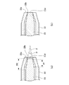
図7は、電圧印加手段50によって、被塗物40と液体噴霧部20及び2つの塗着防止電極30との間に電圧を印加したときの電界の状態(電界の方向)を示した図であり、液体噴霧部20の上側が見える方向から見た上面図になっている。
なお、図7では、電圧印加手段50や電気配線に関しては図示を省略している。
FIG. 7 is a diagram illustrating a state of an electric field (direction of the electric field) when a voltage is applied between the
In FIG. 7, illustration of the
図7を見るとわかるように、やはり、塗着防止電極30が向けられている被塗物40の左右の側面43、44は、塗着防止電極30との間で電界を張るようになっているため、液体噴霧部20との間で電界を張っておらず、このため被塗物40の左右の側面43、44にマスクを設けなくても、液体噴霧部20から噴霧された液体が被塗物40の左右の側面43、44に塗着することがない。
なお、被塗物40の上下面への液体の塗着も防止したい場合には、さらに、上下面に向けて配置する塗着防止電極30を設けるようにすればよい。
As can be seen from FIG. 7, the left and right side surfaces 43, 44 of the
In addition, when it is desired to prevent the liquid from being applied to the upper and lower surfaces of the
このように、被塗物40の前面41に主に液体を塗着させたい場合には、ノズル22の先端から被塗物40を最短距離で結ぶ直線軸(図7のZ軸参照)が被塗物40と交わる点で直線軸(図7のZ軸参照)に直交する平面(前面41参照)を規定したときに、平面を挟んで液体噴霧部20の反対側の適切な位置、例えば、被塗物40の上下左右面に向く位置や第1実施形態のように後面42に向く位置に塗着防止電極30を位置させるようにすればよい。
As described above, when it is desired to apply a liquid mainly to the
特に、第1実施形態のように、平板状の被塗物40の後面42に液体を塗着させない場合には、塗着防止電極30が、被塗物40を挟んで液体噴霧部20と反対側に位置するようにすればよい。
In particular, when the liquid is not applied to the
(第3実施形態)
図8は第3実施形態の静電噴霧装置10を示す斜視図であり、第1実施形態の平板状の被塗物40を円柱状の被塗物40とした点が第1実施形態と異なり、その他の点は第1実施形態と同様である。
このようにすれば、円柱状の被塗物40の液体噴霧部20側を向いた半分の面に液体を塗着させ、残る半分の面に液体を塗着させないようにすることが可能である。
(Third embodiment)
FIG. 8 is a perspective view showing the
In this way, it is possible to apply the liquid to the half surface of the
なお、これまでの実施形態を含め、塗着防止電極30の電位である第2の電位が液体噴霧部20の電位である第1の電位とほぼ同じ電位となる場合について示してきたが、必ずしも第2の電位が第1の電位とほぼ同じ電位である必要はない。
In addition to the embodiments described above, the case where the second potential, which is the potential of the
被塗物40の電位を基準電位としたときに第1の電位と第2の電位の極性の方向が同じになるようにされていればよく、その上で塗着防止電極30の電位である第2の電位をどの程度の電位とするかは、液体を塗着させたくない範囲に応じて変更すればよい。
When the potential of the
例えば、塗着防止電極30に接続される電気配線の途中に可変抵抗を加えるようにすれば、この可変抵抗の抵抗値を変えることで第2の電位を変えることが可能であり、第2の電位を被塗物40の電位である基準電位に近づければ、被塗物40との間で張られる電界が弱くなるので、液体を塗着させない範囲を小さくすることができる。
For example, if a variable resistor is added in the middle of the electric wiring connected to the
逆に、第2の電位を被塗物40の電位である基準電位から離すようにすれば、その分、被塗物40との間で張られる電界が強くなるので、液体を塗着させない範囲を大きくすることができる。
Conversely, if the second electric potential is separated from the reference electric potential which is the electric potential of the
ただし、第1の電位と第2の電位の極性の方向が逆になる場合は、塗着防止電極30が、第1の電位である液体噴霧部20に対する異極になることを意味し、塗着防止電極30と液体噴霧部20との間で電界が張られ、塗着防止電極30が液体噴霧部20から噴霧される液体の塗着するターゲットとなるので、上述のように、被塗物40の電位を基準電位としたときに第1の電位と第2の電位の極性の方向が同じになるようにする必要がある。
However, when the polarity of the first potential is opposite to the polarity of the second potential, it means that the
(第4実施形態)
図9は、第4実施形態の静電噴霧装置10を示す斜視図である。
第4実施形態では、図8に示した構成にノズル22の外周に固定される絶縁材料からなる近接電極ホルダ71を設け、ノズル22の近隣に配置される近接電極70を備えるようにした点が主に異なる。
(Fourth embodiment)
FIG. 9 is a perspective view showing the
The fourth embodiment is different from the configuration shown in FIG. 8 in that a
この近接電極70を設けるにあたっては、電圧印加手段50の近接電極70への電圧の印加が、近接電極70の電位を被塗物40の電位である基準電位と液体噴霧部20の電位である第1の電位の間の第3の電位であって、第1の電位と第3の電位との電位差がノズル22から液体を帯電状態で離脱させる静電気力を発生できる電位差とするように構成すればよい。
In providing the
具体的には、図9に示すように、被塗物40と液体噴霧部20との間に印加される電圧を抵抗Rで分割して、近接電極70の電位を被塗物40の電位である基準電位と液体噴霧部20の電位である第1の電位の中間程度となる第3の電位とすればよい。
Specifically, as shown in FIG. 9, the voltage applied between the
このような近接電極70を設けるようにすれば、ノズル22からの液体の離脱・霧化が主に近接電極70と液体噴霧部20との間で行われるため、被塗物40が配置されていない状態でも霧化を行った状態を維持することができる。
If such a
霧化開始直後は、霧化の状態が安定していない場合があるが、本構成のようにしておけば、霧化が安定したところにコンベア等で被塗物40を液体を噴霧する位置に搬送するようにすれば、霧化開始直後の霧化の状態が安定していない液体が被塗物40に塗着することを回避することができるので、塗布ムラの発生を抑制することが可能である。
Immediately after the start of atomization, the atomization state may not be stable. However, if this configuration is used, the
以上、具体的な実施形態に基づいて本発明の静電噴霧装置について説明してきたが、本発明は、上記の具体的な実施形態に限定されるものではない。
例えば、上記実施形態では、塗着防止電極30が被塗物40の液体を塗着させない部分に向けて配置されている。
しかし、塗着防止電極30が被塗物40の液体を塗着させない部分に向いていなくても、塗着防止電極30は被塗物40の液体を塗着させない部分との間に電界を張るため、液体の塗着を防止することができる。
As mentioned above, although the electrostatic spraying device of the present invention was explained based on a specific embodiment, the present invention is not limited to the above-mentioned specific embodiment.
For example, in the above-described embodiment, the
However, even if the
このため、塗着防止電極30は被塗物40の液体を塗着させない部分との間に電界を張る位置に位置すればよく、被塗物40の液体を塗着させない部分に向けて配置されていることは必須の要件ではない。
For this reason, the
このように、本発明は上記実施形態に限定されるものではなく、適宜、変形や改良を施したものも本発明の技術的範囲に含まれるものであり、そのことは、当業者にとって特許請求の範囲の記載から明らかである。 As described above, the present invention is not limited to the above-described embodiment, and appropriately modified or improved ones are also included in the technical scope of the present invention. It is clear from the description of the range.
10 静電噴霧装置
20 液体噴霧部
21 胴体部
21a 液体供給口
21b 液体流路
21c 孔部
21d 後端開口部
21e 雌ネジ構造
22 ノズル
22a 先端外周縁
22b 開口部
23 心棒
23a 摘み部
23b 電気配線接続部
23c 雄ネジ構造
23d 先端面
24 シール部材
30 塗着防止電極
40 被塗物
41 前面
42 後面
43,44 側面
50 電圧印加手段
60 アース手段
70 近接電極
71 近接電極ホルダ
80 テーラコーン
10
Claims (6)
前記電圧を印加する電圧印加手段と、
前記ノズルを有する前記液体噴霧部と、
前記被塗物の前記液体を塗着させない部分との間に電界を張る塗着防止電極と、を備え、
前記電圧印加手段による前記電圧の印加が、前記被塗物の電位を基準電位としたときに、前記液体噴霧部の電位を前記基準電位と異なる第1の電位とするとともに前記塗着防止電極の電位を前記第1の電位と極性の方向が同じである前記基準電位と異なる第2の電位とするように行われ、
前記塗着防止電極は、前記ノズルの先端から前記被塗物を最短距離で結ぶ直線軸が前記被塗物と交わる点で前記直線軸に直交する平面を規定したときに、前記平面を挟んで前記液体噴霧部の反対側に位置することを特徴とする静電噴霧装置。 An electrostatic spraying device that separates a liquid from a nozzle of a liquid spraying unit in a charged state with an electrostatic force generated by application of a voltage and applies the liquid to an object to be coated,
Voltage applying means for applying the voltage,
The liquid spraying unit having the nozzle,
An anti-adhesion electrode that applies an electric field between the liquid to be applied and a portion of the object to which the liquid is not applied,
The application of the voltage by the voltage applying unit sets the potential of the liquid spraying unit to a first potential different from the reference potential when the potential of the object to be applied is set to a reference potential. The potential is set to be a second potential different from the reference potential having the same polarity direction as the first potential ;
The coating prevention electrode defines a plane perpendicular to the linear axis at a point where a linear axis connecting the object to be coated at the shortest distance from the tip of the nozzle intersects the object to be coated, and sandwiches the plane. An electrostatic spraying device, which is located on the opposite side of the liquid spraying section .
前記電圧を印加する電圧印加手段と、
前記ノズルを有する前記液体噴霧部と、
前記被塗物の前記液体を塗着させない部分との間に電界を張る塗着防止電極と、を備え、
前記電圧印加手段による前記電圧の印加が、前記被塗物の電位を基準電位としたときに、前記液体噴霧部の電位を前記基準電位と異なる第1の電位とするとともに前記塗着防止電極の電位を前記第1の電位と極性の方向が同じである前記基準電位と異なる第2の電位とするように行われ、
前記塗着防止電極は、前記被塗物を挟んで前記液体噴霧部と反対側に位置することを特徴とする静電噴霧装置。 An electrostatic spraying device that separates a liquid from a nozzle of a liquid spraying unit in a charged state with an electrostatic force generated by application of a voltage and applies the liquid to an object to be coated,
Voltage applying means for applying the voltage,
The liquid spraying unit having the nozzle,
An anti-adhesion electrode that applies an electric field between the liquid to be applied and a portion of the object to which the liquid is not applied,
The application of the voltage by the voltage applying unit sets the potential of the liquid spraying unit to a first potential different from the reference potential when the potential of the object to be applied is set to a reference potential. The potential is set to be a second potential different from the reference potential having the same polarity direction as the first potential ;
The electrostatic spraying device according to claim 1, wherein the coating prevention electrode is located on a side opposite to the liquid spraying unit with the object to be coated therebetween .
前記電圧印加手段の電圧の印加が、前記近接電極の電位を前記基準電位と前記第1の電位の間の第3の電位であって、前記第1の電位と前記第3の電位との電位差が前記ノズルから前記液体を帯電状態で離脱させる静電気力を発生できる前記電位差とするように行われることを特徴とする請求項1から請求項5のいずれか1項に記載の静電噴霧装置。 Comprising a proximity electrode arranged near the nozzle,
The application of the voltage by the voltage applying means is performed by setting the potential of the proximity electrode to a third potential between the reference potential and the first potential, and a potential difference between the first potential and the third potential. The electrostatic spraying device according to any one of claims 1 to 5 , wherein the potential difference is set so as to generate an electrostatic force that causes the liquid to separate from the nozzle in a charged state.
Priority Applications (3)
| Application Number | Priority Date | Filing Date | Title |
|---|---|---|---|
| PCT/JP2017/011312 WO2017164198A1 (en) | 2016-03-25 | 2017-03-22 | Electrostatic spray device |
| US16/087,865 US20190091707A1 (en) | 2016-03-25 | 2017-03-22 | Electrostatic spray apparatus |
| EP17770240.4A EP3434376A4 (en) | 2016-03-25 | 2017-03-22 | ELECTROSTATIC SPRAY DEVICE |
Applications Claiming Priority (2)
| Application Number | Priority Date | Filing Date | Title |
|---|---|---|---|
| JP2016062471 | 2016-03-25 | ||
| JP2016062471 | 2016-03-25 |
Publications (2)
| Publication Number | Publication Date |
|---|---|
| JP2017177096A JP2017177096A (en) | 2017-10-05 |
| JP6672575B2 true JP6672575B2 (en) | 2020-03-25 |
Family
ID=60003110
Family Applications (1)
| Application Number | Title | Priority Date | Filing Date |
|---|---|---|---|
| JP2017044550A Active JP6672575B2 (en) | 2016-03-25 | 2017-03-09 | Electrostatic spraying device |
Country Status (3)
| Country | Link |
|---|---|
| US (1) | US20190091707A1 (en) |
| EP (1) | EP3434376A4 (en) |
| JP (1) | JP6672575B2 (en) |
Families Citing this family (3)
| Publication number | Priority date | Publication date | Assignee | Title |
|---|---|---|---|---|
| CN108931967A (en) | 2017-05-22 | 2018-12-04 | 大隈株式会社 | Running monitor device and its control program |
| JP7729531B2 (en) * | 2021-03-04 | 2025-08-26 | 旭サナック株式会社 | Coating Method |
| US20240253068A1 (en) * | 2023-01-31 | 2024-08-01 | 3M Innovative Properties Company | Adhesive spray nozzle and methods of using the same |
Family Cites Families (20)
| Publication number | Priority date | Publication date | Assignee | Title |
|---|---|---|---|---|
| US2773472A (en) * | 1951-08-14 | 1956-12-11 | Gen Motors Corp | Apparatus for electrostatic spray coating |
| JPS4749617B1 (en) * | 1967-04-19 | 1972-12-13 | ||
| CH622444A5 (en) * | 1977-04-04 | 1981-04-15 | Gruenenfelder H Eltex Elektron | |
| US4780331A (en) * | 1984-05-31 | 1988-10-25 | Nordson Corporation | Method and apparatus for induction charging of powder by contact electrification |
| DE3804072A1 (en) * | 1988-02-10 | 1989-08-24 | Behr Industrieanlagen | Method for the electrostatic coating of motor-vehicle bodies and device for carrying out the method |
| US5238709A (en) * | 1991-04-26 | 1993-08-24 | W. R. Grace & Co.-Conn. | Electrostatic spray coating method |
| JPH06126218A (en) * | 1992-10-19 | 1994-05-10 | Taikisha Ltd | Coating booth |
| US5948483A (en) * | 1997-03-25 | 1999-09-07 | The Board Of Trustees Of The University Of Illinois | Method and apparatus for producing thin film and nanoparticle deposits |
| US6743463B2 (en) * | 2002-03-28 | 2004-06-01 | Scimed Life Systems, Inc. | Method for spray-coating a medical device having a tubular wall such as a stent |
| US20050104258A1 (en) * | 2003-07-02 | 2005-05-19 | Physical Sciences, Inc. | Patterned electrospinning |
| TWI257351B (en) * | 2003-08-08 | 2006-07-01 | Sharp Kk | Electrostatic attraction fluid ejecting method and electrostatic attraction fluid ejecting device |
| JP5207334B2 (en) * | 2006-02-28 | 2013-06-12 | 独立行政法人理化学研究所 | Micropattern forming apparatus, micropattern structure, and manufacturing method thereof |
| US8097291B2 (en) * | 2006-06-05 | 2012-01-17 | Boston Scientific Scimed, Inc. | Methods for coating workpieces |
| EP2050507A1 (en) * | 2007-10-17 | 2009-04-22 | J. Wagner AG | Method and device for electrostatic coating of an electrically conductive workpiece with coating powder |
| JP4974923B2 (en) * | 2008-02-06 | 2012-07-11 | 浜松ホトニクス株式会社 | Nanomaterial observation sample preparation apparatus and preparation method |
| JP2010284618A (en) * | 2009-06-15 | 2010-12-24 | Asahi Sunac Corp | Painting equipment |
| NL2008056C2 (en) * | 2011-12-29 | 2013-07-03 | Univ Delft Tech | System and method for delivering sprayed particles by electrospraying. |
| WO2013105558A1 (en) * | 2012-01-11 | 2013-07-18 | コニカミノルタ株式会社 | Electrostatic spray device and manufacturing method of organic thin film device |
| JP5700030B2 (en) * | 2012-12-19 | 2015-04-15 | ダイキン工業株式会社 | Deposition equipment |
| JP6264275B2 (en) * | 2014-12-12 | 2018-01-24 | 株式会社島津製作所 | Matrix film forming equipment |
-
2017
- 2017-03-09 JP JP2017044550A patent/JP6672575B2/en active Active
- 2017-03-22 US US16/087,865 patent/US20190091707A1/en not_active Abandoned
- 2017-03-22 EP EP17770240.4A patent/EP3434376A4/en not_active Withdrawn
Also Published As
| Publication number | Publication date |
|---|---|
| US20190091707A1 (en) | 2019-03-28 |
| EP3434376A4 (en) | 2019-11-27 |
| EP3434376A1 (en) | 2019-01-30 |
| JP2017177096A (en) | 2017-10-05 |
Similar Documents
| Publication | Publication Date | Title |
|---|---|---|
| JP6657505B2 (en) | Electrostatic spray device and electrostatic spray method | |
| JP6657504B2 (en) | Electrostatic spraying device | |
| JP6589280B2 (en) | Electrostatic spraying equipment | |
| JP6473629B2 (en) | Electrostatic spraying equipment | |
| JP6750167B2 (en) | Electrostatic spraying device | |
| JP6672575B2 (en) | Electrostatic spraying device | |
| JP2024091756A (en) | Masking jig | |
| JP6634645B2 (en) | Masking jig for electrostatic spraying device, electrostatic spraying device provided with the masking jig, and electrostatic spraying method using the masking jig | |
| JP2017074568A (en) | Liquid coating method using masking jig, masking jig for the same, and electrostatic atomizer using masking jig | |
| JP6494095B2 (en) | Electrostatic spraying equipment | |
| JP6485951B2 (en) | Electrostatic spray device flow rate adjustment method and electrostatic spray device capable of adjusting the flow rate | |
| JP6743345B2 (en) | Electrostatic spraying device and electrostatic spraying method | |
| JP6494090B2 (en) | Electrostatic spraying equipment | |
| JP2019058862A (en) | Electrostatic spraying method and electrostatic spraying apparatus therefor | |
| JP2017170412A (en) | Electrostatic atomizer and electrostatic atomization method | |
| WO2017164198A1 (en) | Electrostatic spray device | |
| JP6473643B2 (en) | Electrostatic spraying equipment | |
| JP6613481B2 (en) | Liquid coating method | |
| JP6678891B2 (en) | Liquid coating method and electrostatic spraying device used therefor | |
| JP6926370B2 (en) | Electrostatic spraying method and electrostatic spraying device for the electrostatic spraying method | |
| JP7502896B2 (en) | Electrostatic spraying device | |
| JP2017100080A (en) | Electrostatic spraying method and electrostatic spraying apparatus | |
| JP2017056435A (en) | Electrostatic atomizer booth and electrostatic atomizer equipped with booth | |
| WO2019221100A1 (en) | Masking jig | |
| WO2020110707A1 (en) | Masking jig and electrostatic spray device |
Legal Events
| Date | Code | Title | Description |
|---|---|---|---|
| A621 | Written request for application examination |
Free format text: JAPANESE INTERMEDIATE CODE: A621 Effective date: 20190204 |
|
| A131 | Notification of reasons for refusal |
Free format text: JAPANESE INTERMEDIATE CODE: A131 Effective date: 20191015 |
|
| A521 | Request for written amendment filed |
Free format text: JAPANESE INTERMEDIATE CODE: A523 Effective date: 20191129 |
|
| TRDD | Decision of grant or rejection written | ||
| A01 | Written decision to grant a patent or to grant a registration (utility model) |
Free format text: JAPANESE INTERMEDIATE CODE: A01 Effective date: 20200204 |
|
| A61 | First payment of annual fees (during grant procedure) |
Free format text: JAPANESE INTERMEDIATE CODE: A61 Effective date: 20200214 |
|
| A621 | Written request for application examination |
Free format text: JAPANESE INTERMEDIATE CODE: A621 Effective date: 20200220 |
|
| R150 | Certificate of patent or registration of utility model |
Ref document number: 6672575 Country of ref document: JP Free format text: JAPANESE INTERMEDIATE CODE: R150 |
|
| R250 | Receipt of annual fees |
Free format text: JAPANESE INTERMEDIATE CODE: R250 |
|
| R250 | Receipt of annual fees |
Free format text: JAPANESE INTERMEDIATE CODE: R250 |
|
| R250 | Receipt of annual fees |
Free format text: JAPANESE INTERMEDIATE CODE: R250 |
|
| R250 | Receipt of annual fees |
Free format text: JAPANESE INTERMEDIATE CODE: R250 |