JP6666446B2 - Heat flow sensor - Google Patents
Heat flow sensor Download PDFInfo
- Publication number
- JP6666446B2 JP6666446B2 JP2018532172A JP2018532172A JP6666446B2 JP 6666446 B2 JP6666446 B2 JP 6666446B2 JP 2018532172 A JP2018532172 A JP 2018532172A JP 2018532172 A JP2018532172 A JP 2018532172A JP 6666446 B2 JP6666446 B2 JP 6666446B2
- Authority
- JP
- Japan
- Prior art keywords
- thermistor
- temperature
- heat flow
- flow sensor
- sensor
- Prior art date
- Legal status (The legal status is an assumption and is not a legal conclusion. Google has not performed a legal analysis and makes no representation as to the accuracy of the status listed.)
- Active
Links
- 238000009529 body temperature measurement Methods 0.000 claims description 49
- 230000009977 dual effect Effects 0.000 claims description 25
- 239000002131 composite material Substances 0.000 claims description 19
- 238000011156 evaluation Methods 0.000 claims description 19
- 238000000034 method Methods 0.000 claims description 15
- 238000012544 monitoring process Methods 0.000 claims description 12
- 238000012935 Averaging Methods 0.000 claims 1
- 150000001875 compounds Chemical group 0.000 claims 1
- 238000001514 detection method Methods 0.000 claims 1
- 230000036757 core body temperature Effects 0.000 description 25
- 230000008901 benefit Effects 0.000 description 7
- 230000036760 body temperature Effects 0.000 description 7
- 230000002631 hypothermal effect Effects 0.000 description 7
- 238000012546 transfer Methods 0.000 description 7
- 238000010586 diagram Methods 0.000 description 5
- 239000000463 material Substances 0.000 description 5
- 238000004364 calculation method Methods 0.000 description 4
- 238000010438 heat treatment Methods 0.000 description 4
- 230000007613 environmental effect Effects 0.000 description 3
- 230000004907 flux Effects 0.000 description 3
- 239000010410 layer Substances 0.000 description 3
- 239000011159 matrix material Substances 0.000 description 3
- 238000005259 measurement Methods 0.000 description 3
- 230000005540 biological transmission Effects 0.000 description 2
- 238000004422 calculation algorithm Methods 0.000 description 2
- 230000001419 dependent effect Effects 0.000 description 2
- 238000001356 surgical procedure Methods 0.000 description 2
- 206010002091 Anaesthesia Diseases 0.000 description 1
- 206010020843 Hyperthermia Diseases 0.000 description 1
- 125000002066 L-histidyl group Chemical group [H]N1C([H])=NC(C([H])([H])[C@](C(=O)[*])([H])N([H])[H])=C1[H] 0.000 description 1
- 230000037005 anaesthesia Effects 0.000 description 1
- 210000001367 artery Anatomy 0.000 description 1
- 238000013142 basic testing Methods 0.000 description 1
- 230000000740 bleeding effect Effects 0.000 description 1
- 230000000747 cardiac effect Effects 0.000 description 1
- 210000001715 carotid artery Anatomy 0.000 description 1
- 230000008859 change Effects 0.000 description 1
- 238000007796 conventional method Methods 0.000 description 1
- 230000000694 effects Effects 0.000 description 1
- 210000003238 esophagus Anatomy 0.000 description 1
- 230000001747 exhibiting effect Effects 0.000 description 1
- 230000036031 hyperthermia Effects 0.000 description 1
- 230000002977 hyperthermial effect Effects 0.000 description 1
- 208000015181 infectious disease Diseases 0.000 description 1
- 239000011810 insulating material Substances 0.000 description 1
- 238000009413 insulation Methods 0.000 description 1
- 230000007774 longterm Effects 0.000 description 1
- 238000012986 modification Methods 0.000 description 1
- 230000004048 modification Effects 0.000 description 1
- 230000007935 neutral effect Effects 0.000 description 1
- 230000002085 persistent effect Effects 0.000 description 1
- 230000008569 process Effects 0.000 description 1
- 239000011241 protective layer Substances 0.000 description 1
- 210000000664 rectum Anatomy 0.000 description 1
- 230000004044 response Effects 0.000 description 1
- 239000000523 sample Substances 0.000 description 1
- 230000035945 sensitivity Effects 0.000 description 1
- 230000035939 shock Effects 0.000 description 1
- 210000003708 urethra Anatomy 0.000 description 1
Images


Classifications
-
- A—HUMAN NECESSITIES
- A61—MEDICAL OR VETERINARY SCIENCE; HYGIENE
- A61B—DIAGNOSIS; SURGERY; IDENTIFICATION
- A61B5/00—Measuring for diagnostic purposes; Identification of persons
- A61B5/01—Measuring temperature of body parts ; Diagnostic temperature sensing, e.g. for malignant or inflamed tissue
-
- G—PHYSICS
- G01—MEASURING; TESTING
- G01K—MEASURING TEMPERATURE; MEASURING QUANTITY OF HEAT; THERMALLY-SENSITIVE ELEMENTS NOT OTHERWISE PROVIDED FOR
- G01K1/00—Details of thermometers not specially adapted for particular types of thermometer
- G01K1/16—Special arrangements for conducting heat from the object to the sensitive element
- G01K1/165—Special arrangements for conducting heat from the object to the sensitive element for application in zero heat flux sensors
-
- G—PHYSICS
- G01—MEASURING; TESTING
- G01K—MEASURING TEMPERATURE; MEASURING QUANTITY OF HEAT; THERMALLY-SENSITIVE ELEMENTS NOT OTHERWISE PROVIDED FOR
- G01K13/00—Thermometers specially adapted for specific purposes
- G01K13/20—Clinical contact thermometers for use with humans or animals
-
- G—PHYSICS
- G01—MEASURING; TESTING
- G01K—MEASURING TEMPERATURE; MEASURING QUANTITY OF HEAT; THERMALLY-SENSITIVE ELEMENTS NOT OTHERWISE PROVIDED FOR
- G01K7/00—Measuring temperature based on the use of electric or magnetic elements directly sensitive to heat ; Power supply therefor, e.g. using thermoelectric elements
- G01K7/42—Circuits effecting compensation of thermal inertia; Circuits for predicting the stationary value of a temperature
- G01K7/427—Temperature calculation based on spatial modeling, e.g. spatial inter- or extrapolation
-
- A—HUMAN NECESSITIES
- A61—MEDICAL OR VETERINARY SCIENCE; HYGIENE
- A61B—DIAGNOSIS; SURGERY; IDENTIFICATION
- A61B2505/00—Evaluating, monitoring or diagnosing in the context of a particular type of medical care
- A61B2505/05—Surgical care
-
- A—HUMAN NECESSITIES
- A61—MEDICAL OR VETERINARY SCIENCE; HYGIENE
- A61B—DIAGNOSIS; SURGERY; IDENTIFICATION
- A61B2562/00—Details of sensors; Constructional details of sensor housings or probes; Accessories for sensors
- A61B2562/02—Details of sensors specially adapted for in-vivo measurements
- A61B2562/0271—Thermal or temperature sensors
-
- A—HUMAN NECESSITIES
- A61—MEDICAL OR VETERINARY SCIENCE; HYGIENE
- A61B—DIAGNOSIS; SURGERY; IDENTIFICATION
- A61B2562/00—Details of sensors; Constructional details of sensor housings or probes; Accessories for sensors
- A61B2562/04—Arrangements of multiple sensors of the same type
- A61B2562/046—Arrangements of multiple sensors of the same type in a matrix array
-
- A—HUMAN NECESSITIES
- A61—MEDICAL OR VETERINARY SCIENCE; HYGIENE
- A61B—DIAGNOSIS; SURGERY; IDENTIFICATION
- A61B5/00—Measuring for diagnostic purposes; Identification of persons
- A61B5/0002—Remote monitoring of patients using telemetry, e.g. transmission of vital signals via a communication network
- A61B5/0015—Remote monitoring of patients using telemetry, e.g. transmission of vital signals via a communication network characterised by features of the telemetry system
- A61B5/002—Monitoring the patient using a local or closed circuit, e.g. in a room or building
Description
本発明は、熱流センサ、熱流センサにより対象の温度を測定する方法、及び温度検知配置に関する。 The present invention relates to a heat flow sensor, a method for measuring the temperature of an object with a heat flow sensor, and a temperature sensing arrangement.
中核体温(CBT;Core Body Temperature)は、医療環境において重要なバイタルサインである。麻酔状態下の患者は、彼/彼女の体温を調節することができず、手術室は、一般的に、低い温度に冷やされる。身体の中核温が36度を下回って潜在的に危険な温度まで下がると、低体温症が起きる。外科患者は、手術室から出るとしばしば体温が降下している。体温降下作用は組織へのショックとなるので、低体温の患者は、特に手術後の最初の24時間の間に、心臓合併症のリスクがある。低体温症に関連した他の問題は、感染症及び出血のリスク増加である。そのような理由により、CBTは、一般的に、医療処置中に、又は回復患者の長期モニタリングの間に、念入りにモニタされる。従来の方法は、加熱要素及び加熱要素を制御する制御ループを必要とする能動型熱流センサ又は侵入的なプローブ(食道、直腸、尿道)を伴いうる。 Core body temperature (CBT) is an important vital sign in the medical setting. A patient under anesthesia is unable to regulate his / her temperature and the operating room is typically cooled to a lower temperature. Hypothermia occurs when the body's core temperature falls below 36 degrees to a potentially dangerous temperature. Surgical patients often have a drop in body temperature as they leave the operating room. Hypothermic patients are at risk for cardiac complications, especially during the first 24 hours after surgery, as the hypothermic effect results in tissue shock. Another problem associated with hypothermia is the increased risk of infection and bleeding. For such reasons, CBT is generally monitored closely during medical procedures or during long-term monitoring of a recuperating patient. Conventional methods can involve active heat flow sensors or invasive probes (esophagus, rectum, urethra) that require a heating element and a control loop to control the heating element.
加熱要素を必要としない受動型熱流センサは、それらが患者にとってそれほど危険でないという利点を有し、比較的にほとんど電力を消費しない。従来の熱流センサは、外向き方向(例えば、センサが適用される皮膚の表面に対して外側)においてしか熱流を測定することができない。しかし、中核体温は、身体から外に向かってだけでなく、全ての方向において流れる。そのため、従来の受動型熱流センサは、センサが適切に断熱されない限り、一般的に、必要な精度で中核体温を測定することができない(このことは、周囲の断熱によりセンサのサイズを大きくする。)。もう一つの問題は、身体とセンサとの間の接触域が滅多に熱的に一様でない点である。特に、これは、センサの接触域が一般的に極めて大きくなければならないからである。例えば、患者の頭部にわたる温度プロファイルは、皮膚の下の動脈の位置によって著しい違いを示しうる。2つ以上の縦型サーミスタ配置を使用する従来型の受動型熱流センサは、皮膚へのセンサの接着不足に起因して、又はセンサと皮膚との間の空洞部分に起因して、不正確な温度測定を提供しうる。そのような状況は、あちこち移動する患者によって装着された装着型センサの場合に起こることがある。更に、従来の熱流センサは、周囲温度の変化に極めて敏感である。 Passive heat flow sensors that do not require a heating element have the advantage that they are less dangerous to the patient and consume relatively little power. Conventional heat flow sensors can only measure heat flow in an outward direction (eg, outside of the surface of the skin to which the sensor is applied). However, core body temperature flows in all directions, not just outward from the body. As such, conventional passive heat flow sensors generally cannot measure core body temperature with the required accuracy unless the sensor is properly insulated (this increases the size of the sensor due to the surrounding insulation). ). Another problem is that the contact area between the body and the sensor is rarely thermally uniform. In particular, this is because the contact area of the sensor must generally be very large. For example, the temperature profile over the patient's head can show significant differences depending on the location of the artery below the skin. Conventional passive heat flow sensors that use two or more vertical thermistor arrangements have inaccurate due to poor adhesion of the sensor to the skin or due to the cavity between the sensor and the skin. A temperature measurement may be provided. Such a situation may occur with a wearable sensor worn by a moving patient. Further, conventional heat flow sensors are extremely sensitive to changes in ambient temperature.
従って、本発明の目的は、対象の温度を測定する改善された熱流センサを提供することである。 Accordingly, it is an object of the present invention to provide an improved heat flow sensor for measuring the temperature of an object.
本発明の目的は、請求項1の受動型熱流センサによって;そのような受動型熱流センサにより対象の温度を測定する請求項7の方法によって;及び請求項11の温度検知配置によって達成される。
The object of the invention is achieved by a passive heat flow sensor of
熱流センサは、温度監視プロシージャの間に対象に置かれる接触面を有する。本発明に従って、熱流センサは、複数の複合サーミスタ配置を有し、夫々の複合サーミスタ配置は、(センサの内面に配置される)内部サーミスタと、(センサの上面に配置され、)対象から外へ向かう垂直な熱流を測定するよう、すなわち、内部サーミスタと上部サーミスタとの間の熱流を測定するよう内部サーミスタに対して配置される上部サーミスタと、更には、接触面に沿って水平な熱流を測定するよう、すなわち、内部サーミスタと側方サーミスタとの間の熱流を更に測定するよう内部サーミスタに対して配置される側方サーミスタとを有する。 The heat flow sensor has a contact surface that is placed on an object during a temperature monitoring procedure. In accordance with the present invention, the heat flow sensor has a plurality of composite thermistor arrangements, each composite thermistor arrangement including an internal thermistor (located on the inner surface of the sensor) and an outgoing object (located on the upper surface of the sensor). An upper thermistor positioned relative to the internal thermistor to measure the heat flow perpendicular to it, i.e. between the internal thermistor and the upper thermistor, and also to measure the horizontal heat flow along the contact surface A lateral thermistor positioned relative to the internal thermistor to further measure the heat flow between the internal and lateral thermistors.
特許請求の範囲で使用される幾何学用語は、対象の外面を表す仮定の水平面と関係しており、基準スペースを画定するためにしか用いない。従って、“水平な熱流”は、対象の表面に沿ったあらゆる熱流であり、“垂直な熱流”は、対象の表面から外へ向かうあらゆる熱流である。実際には、センサは、例えば、患者の皮膚に取り付けられる場合に、如何なる位置付けも取ることができる点が理解されるべきである。 The geometric terms used in the claims relate to a hypothetical horizontal plane representing the outer surface of the object and are only used to define a reference space. Thus, "horizontal heat flow" is any heat flow along the surface of the object, and "vertical heat flow" is any heat flow out of the surface of the object. In fact, it should be understood that the sensor can take any position, for example when mounted on the skin of a patient.
本発明と関連して、1つのサーミスタの他のサーミスタに対する配置は、本質的に、ある方向に整列され、熱流がその方向に沿って測定されるべきであるということを意味すると理解されるべきである。ここでも、幾何学用語“上部”、“内部”及び“外部”は、基準スペースと関連して使用される。従って、内部サーミスタはセンサの内面に配置され、上部サーミスタは、センサの外面に向いて配置され、それにより、上部サーミスタは、対象から外へ向かう熱流を測定するよう内部サーミスタと垂直に列となるようにされることが理解されるだろう。外へ向かう熱流は、対象がセンサよりも温かい場合には、内部サーミスタから上部サーミスタへの向きであり、対象がセンサよりも冷たい場合には、熱流の方向は逆になる。同様に、側方サーミスタは、対象の表面に沿って、例えば、患者の皮膚に沿って熱流を測定するよう内部サーミスタと列になって配置されることが理解されるだろう。横に向かう熱流は、内部サーミスタから側方サーミスタの間の向きであり、内部センサ領域と側方サーミスタを含むセンサの側面との間の如何なる温度差も検出する働きをする。 In the context of the present invention, the arrangement of one thermistor relative to another thermistor is to be understood as meaning essentially that it is aligned in one direction and the heat flow should be measured along that direction. It is. Again, the geometric terms “top”, “inside” and “outside” are used in connection with the reference space. Thus, the inner thermistor is located on the inner surface of the sensor and the upper thermistor is located facing the outer surface of the sensor, so that the upper thermistor is in a row perpendicular to the inner thermistor to measure the heat flow out of the object. It will be understood that it will be. The outward heat flow is from the internal thermistor to the upper thermistor if the object is warmer than the sensor, and the direction of the heat flow is reversed if the object is cooler than the sensor. Similarly, it will be appreciated that the lateral thermistor is arranged in line with the internal thermistor to measure heat flow along the surface of the object, for example, along the patient's skin. The lateral heat flow is in the direction between the internal thermistor and the lateral thermistor and serves to detect any temperature difference between the internal sensor area and the side of the sensor containing the lateral thermistor.
本発明に従う熱流センサの利点は、通常の縦型熱流モニタと横型熱流モニタとの組み合わせがより一層正確な温度測定を可能にする点である。特に、これは、横方向の熱流が、(いくつかの従来の熱流センサの場合のように)単に推定されるのではなく、明白に測定されるからである。対象、例えば、手術中及びその後の患者の中核体温は、より高い精度で決定され得る。それにより、低体温症のような危機的な状況は検出されて、タイムリーに処置され得る。 An advantage of the heat flow sensor according to the present invention is that the combination of a conventional vertical heat flow monitor and a horizontal heat flow monitor allows for more accurate temperature measurement. In particular, this is because the lateral heat flow is measured explicitly rather than simply estimated (as in some conventional heat flow sensors). The core body temperature of a subject, eg, during and after surgery, of a patient can be determined with greater accuracy. Thereby, critical situations such as hypothermia can be detected and treated in a timely manner.
本発明に従って、そのような受動型熱流センサにより対象の温度を測定する方法は、温度監視プロシージャの間に対象に熱流センサの接触面を置くステップと、熱流センサの少なくとも1つの複合サーミスタ配置によって収集された温度測定を受け取るステップと、該温度測定から対象の温度を計算するステップとを有する。 In accordance with the present invention, a method for measuring the temperature of an object with such a passive heat flow sensor comprises the steps of placing the contact surface of the heat flow sensor on the object during a temperature monitoring procedure and collecting by at least one composite thermistor arrangement of the heat flow sensor. Receiving the measured temperature measurement and calculating the temperature of the object from the temperature measurement.
本発明の方法は、本発明の熱流センサにおける複合サーミスタ配置の横方向の熱流モニタによって提供される追加情報によって有利に正確な結果を示すことができる。これは、正確な温度監視が、例えば、患者の中核体温に関する正確な情報を医療関係者に提供するために必要とされる状況において、例えば、早急な意志決定を要する緊急事態において、非常に有利となり得る。 The method of the present invention can advantageously provide accurate results with the additional information provided by the lateral heat flow monitor of the composite thermistor arrangement in the heat flow sensor of the present invention. This is a great advantage in situations where accurate temperature monitoring is required, for example, to provide medical personnel with accurate information about the patient's core body temperature, for example, in emergency situations that require immediate decision making. Can be
本発明に従って、温度検知配置は、そのような熱流センサと、サーミスタから温度測定値を受け取り、該温度測定値に基づいて対象の温度を計算するよう配置される評価ユニットとを有する。 According to the invention, the temperature sensing arrangement comprises such a heat flow sensor and an evaluation unit arranged to receive a temperature measurement from the thermistor and calculate a temperature of the object based on the temperature measurement.
従属請求項及び以下の記載は、本発明の特に有利な実施形態及び特徴を開示する。実施形態の特徴は、必要に応じて組み合わされてよい。1つの請求項カテゴリと関連して記載される特徴は、他の請求項カテゴリに同様に適用され得る。 The dependent claims and the following description disclose particularly advantageous embodiments and features of the invention. The features of the embodiments may be combined as needed. Features described in connection with one claim category may be applied to other claim categories as well.
本発明と関連して、用語“対象”は、如何なる生物にも関係があり得る。重大な熱的条件は、一般的に、人間の患者が低体温症又は高熱の状態に入りうる手術状況、緊急医療状況、などと関連して起きる。従って、決して本発明を制限せずに、語“対象”及び「患者」は、以下において同義語と見なされてよい。本発明と関連して以下で使用される語“熱流センサ”は、受動型熱流センサを指すと考えられてよい。望ましくは、受動型熱流センサは、発泡材料から作られ、本発明の熱流センサの外面は、周囲環境に一様にさらされる。更に望ましい実施形態では、センサの上の位置にある適切な材料の均一な層は、センサをダメージから守るために使用されてよい。なお、そのような保護層の如何なる熱的影響も各上部サーミスタに同等に適用されるだろうことが理解されるべきである。換言すれば、本発明の受動型熱流センサの上部サーミスタは、周囲環境によって一様に影響を及ぼされるよう配置される。 In the context of the present invention, the term “subject” can relate to any organism. Significant thermal conditions generally occur in connection with surgical situations, emergency medical situations, etc. where a human patient can enter a hypothermic or hyperthermic state. Thus, without limiting the invention in any way, the words "subject" and "patient" may be considered as synonyms in the following. The term "heat flow sensor" used below in connection with the present invention may be considered to refer to a passive heat flow sensor. Desirably, the passive heat flow sensor is made from a foamed material, and the outer surface of the heat flow sensor of the present invention is uniformly exposed to the surrounding environment. In a further preferred embodiment, a uniform layer of a suitable material above the sensor may be used to protect the sensor from damage. It should be understood that any thermal effects of such a protective layer would apply equally to each upper thermistor. In other words, the upper thermistor of the passive heat flow sensor of the present invention is arranged to be uniformly affected by the surrounding environment.
サーミスタは、温度の変化に応答して電気抵抗が変化するデバイスであり、熱流センサの材料に組み込まれ得る。サーミスタは、2つの電気コネクタを備えた部品として実現され、それにより、それは、適切な回路に含まれ得る。温度変化は、回路による実現化次第で、電流又は電圧の変化として記録される。サーミスタ部品は、小型集積回路(IC;Integrated Circuit)デバイスとしても実現され得る。 A thermistor is a device whose electrical resistance changes in response to a change in temperature and can be incorporated into the material of the heat flow sensor. The thermistor is realized as a component with two electrical connectors, so that it can be included in a suitable circuit. Temperature changes are recorded as changes in current or voltage, depending on the implementation by the circuit. The thermistor component can also be realized as a small integrated circuit (IC) device.
導入部で示されているように、サーミスタ対の1つ以上の縦型配置を使用する受動型熱流センサは先行技術から知られている。本発明の熱流センサは、患者の表面に沿って横方向の熱流も検出及び測定することで温度測定の感度を高め、患者の温度は、縦方向の熱流及び横方向の熱流の測定から推定される。本発明の熱流センサは、以下では単に改良型熱流センサと呼ばれることがある。以下で、語“複合サーミスタ配置”及び“改良型サーミスタ配置”は、従って、同義的に使用されてよい。同様に、語“サーミスタ配置”及び“サーミスタ構成”は同義的に使用されてよい。語“温度測定値”は、サーミスタによって評価ユニットへ報告される量として理解されるべきであり、一方、語“温度測定”は、対象の検知された温度、すなわち、熱流センサの評価ユニットによって、又は温度検知配置の評価ユニットによって報告される温度に関係がある。 As shown in the introduction, passive heat flow sensors that use one or more vertical arrangements of thermistor pairs are known from the prior art. The heat flow sensor of the present invention increases the sensitivity of the temperature measurement by also detecting and measuring the lateral heat flow along the patient's surface, and the patient's temperature is estimated from the longitudinal and lateral heat flow measurements. You. The heat flow sensor of the present invention may be hereinafter simply referred to as an improved heat flow sensor. In the following, the terms "composite thermistor arrangement" and "improved thermistor arrangement" may therefore be used interchangeably. Similarly, the terms “thermistor configuration” and “thermistor configuration” may be used interchangeably. The term "temperature measurement" is to be understood as the quantity reported by the thermistor to the evaluation unit, while the term "temperature measurement" is the sensed temperature of the object, i.e. Or it is related to the temperature reported by the evaluation unit of the temperature sensing arrangement.
2つのサーミスタ(内部サーミスタ及び上部サーミスタ;内部サーミスタ及び側方サーミスタ)の間の中間経路の熱伝導抵抗は、センサの材料及びセンサの厚さのような温度モニタの構造特性によって決定される。熱伝導抵抗は測定可能であり、既知の量であり得る。 The heat transfer resistance of the intermediate path between the two thermistors (internal and upper thermistor; internal and side thermistor) is determined by the structural properties of the temperature monitor, such as the material of the sensor and the thickness of the sensor. Heat transfer resistance is measurable and can be a known quantity.
正確な温度検知のために、本発明の熱流センサの如何なる内部サーミスタも、望ましくは、センサの接触面に近く、あるいはそれと一致する。同様に、改良型サーミスタ構成の如何なる側方サーミスタも、望ましくは、センサの外側領域に向いて位置付けられ、やはりセンサの接触面に近く、あるいはそれと一致する。如何なる上部サーミスタも、望ましくは、センサの“最上”面、すなわち、センサに取り付けられる場合にその外面に近い。 For accurate temperature sensing, any internal thermistor of the heat flow sensor of the present invention is desirably close to or coincident with the contact surface of the sensor. Similarly, any lateral thermistor of the improved thermistor configuration is desirably positioned toward the outer region of the sensor, again close to or coincident with the contact surface of the sensor. Any upper thermistor is desirably close to the "top" surface of the sensor, ie, its outer surface when attached to the sensor.
本発明の1つの好適な実施形態では、サーミスタは、ワイヤ接続を介して評価ユニットへ接続され得る。例えば、温度測定値は、ケーブル接続によってセンサへ接続されている評価ユニットによって受け取られ得る。本発明の他の好適な実施形態では、センサは、温度測定値を無線で評価モジュールへ送信するインターフェイスを装備され得る。センサはまた、アナログの測定値をデータ送信のためにデジタル値に変換するアナログ−デジタル・コンバータを組み込んでよい。本発明の温度検知配置の熱流センサは、望ましくは、装着型デバイスとして実現され得る。すなわち、患者は、長期の温度監視インターバルのために熱流センサを身に付けることができる。本発明の温度検知配置の評価ユニットは、望ましくは、ポータブル・デバイスとして実現され得る。例えば、患者又は何らかの医療関係者は、温度展開を観察するために、タブレット・コンピュータ又はスマートフォンのような、ディスプレイを備えた手持ち式デバイスを使用することができる。装着の実現化において、温度監視の結果は、スマート・ウォッチ又は同様のデバイスのディスプレイ上に示され得る。本発明の更なる好適な実施形態では、温度検知配置は、外科手術の現場における手術台、病院のベッドのマットレス、乳児のスリーピング・バッグ又は新生児病棟の保育器、などのような患者支持デバイスに組み込まれ得る。 In one preferred embodiment of the invention, the thermistor may be connected to the evaluation unit via a wire connection. For example, a temperature measurement may be received by an evaluation unit connected to the sensor by a cable connection. In another preferred embodiment of the invention, the sensor may be equipped with an interface for transmitting temperature measurements wirelessly to the evaluation module. The sensor may also incorporate an analog-to-digital converter that converts analog measurements to digital values for data transmission. The heat flow sensor of the temperature sensing arrangement of the present invention can be desirably implemented as a wearable device. That is, the patient can wear a heat flow sensor for an extended temperature monitoring interval. The evaluation unit of the temperature-sensing arrangement of the present invention can preferably be realized as a portable device. For example, a patient or some medical personnel can use a hand-held device with a display, such as a tablet computer or smartphone, to observe temperature evolution. In the mounting realization, the results of the temperature monitoring may be shown on the display of a smart watch or similar device. In a further preferred embodiment of the present invention, the temperature sensing arrangement is mounted on a patient support device such as an operating table at a surgical site, a hospital bed mattress, an infant sleeping bag or an incubator in a neonatal ward, and the like. Can be incorporated.
本発明の熱流センサの比較的簡単な実施形態では、単一の内部サーミスタが使用され、これは上部サーミスタへ、そして、深部体温の正確な推定のための有利なサイド補償を達成するために側方サーミスタへも接続される。温度監視インターバルの間、3つのサーミスタの温度が観察される。深部体温Tdb(中核体温)は、次の式(1)として表され得る: In a relatively simple embodiment of the heat flow sensor of the present invention, a single internal thermistor is used, which is coupled to the upper thermistor and to achieve advantageous side compensation for accurate estimation of core body temperature. Thermistor is also connected. During the temperature monitoring interval, the temperatures of the three thermistors are observed. The core body temperature T db (core body temperature) can be expressed as the following equation (1):

改良型サーミスタ構成の垂直及び側方サーミスタ対の両方に共通する内部サーミスタは、センサの中心近くに、望ましくは、可能な限り接触面に近く位置付けられ得る。この配置は、単一の改良型サーミスタ構成しか有さない本発明の熱流センサの正攻法の実現にとって好まれ得る。そのような“改良型単一熱流センサ”は、患者の皮膚に沿った1つの横方向における温度測定によって改善又は増強された、患者からの外向きの熱流に関する温度測定を提供することができる。この構成は、患者の中核体温の比較的正確な推定を既に可能にする。 An internal thermistor common to both the vertical and side thermistor pairs of the improved thermistor configuration may be located near the center of the sensor, and preferably as close as possible to the contact surface. This arrangement may be preferred for straightforward implementation of the heat flow sensor of the present invention having only a single improved thermistor configuration. Such an "improved single heat flow sensor" can provide a temperature measurement for outward heat flow from a patient that is improved or enhanced by one lateral temperature measurement along the patient's skin. This configuration already allows a relatively accurate estimation of the patient's core body temperature.
本発明の熱流センサは、そのような改良型サーミスタ配置のみを有することができる。それらの配置は、互いから離れて別個であることができる。同様に、本発明の熱流センサは、改良型サーミスタ配置の構成を与える複数の垂直なサーミスタ対を有することができ、夫々の配置は、垂直なサーミスタ対と、隣接する対の下側のサーミスタとを有する。本発明の代替の実施形態では、改良型サーミスタ配置は、単一の内部サーミスタ及び単一の上部サーミスタを共有する。この改良型単一熱流センサは、内部サーミスタ及び上部サーミスタを通る1つの垂直方向において熱流を測定し、いくつかの横道又は横方向において熱流を測定することで得られる追加情報によって垂直熱流情報を増補する。そのために、夫々の横方向は、内部サーミスタ及び1つの側方サーミスタを有効に通る。1つよりも多い側方サーミスタを組み込むことによって、1つよりも多い横方向において熱流をモニタすることが可能であり、センサ接触面の下のエリアの熱的挙動のより良い推定を可能にする。複合サーミスタ配置の側方サーミスタは、接触面に配置される孤立したサーミスタであることができ、代替的に、複合サーミスタ配置の側方サーミスタは、垂直なサーミスタ対の内部サーミスタであることができる。 The heat flow sensor of the present invention can have only such an improved thermistor arrangement. Their arrangement can be separate and distinct from each other. Similarly, the heat flow sensor of the present invention may have a plurality of vertical thermistor pairs that provide an improved thermistor arrangement, each arrangement comprising a vertical thermistor pair and a lower thermistor of an adjacent pair. Having. In an alternative embodiment of the present invention, the improved thermistor arrangement shares a single internal thermistor and a single upper thermistor. This improved single heat flow sensor measures heat flow in one vertical direction through an internal thermistor and an upper thermistor, and augments the vertical heat flow information with additional information obtained by measuring the heat flow in several lateral paths or lateral directions. I do. To that end, each lateral direction effectively passes through the internal thermistor and one lateral thermistor. By incorporating more than one lateral thermistor, it is possible to monitor heat flow in more than one lateral direction, allowing a better estimation of the thermal behavior of the area under the sensor contact surface . The lateral thermistor of the composite thermistor arrangement can be an isolated thermistor located at the contact surface; alternatively, the lateral thermistor of the composite thermistor arrangement can be the internal thermistor of a vertical thermistor pair.
他の好適な実施形態では、その改良型サーミスタ配置に加えて、本発明の熱流センサは、更なる内部サーミスタと、その内部サーミスタに対して配置されて、対象から外へ向かう更なる垂直な熱流を測定するようにされる更なる上部サーミスタとを備えた別個の縦型サーミスタ配置を有する。この追加の縦型サーミスタ配置は、如何なる複合サーミスタ配置からも機能上独立しており、そのような実施形態は、改良型デュアル(dual)熱流センサと呼ばれてよい。望ましくは、縦型サーミスタ配置は、熱流センサにおいて中心に位置付けられる。中心に位置付けられ且つ独立した縦型サーミスタ配置は、例えば、複数の等距離に配置された改良型サーミスタ構成が横に配置され得る。 In another preferred embodiment, in addition to the improved thermistor arrangement, the heat flow sensor of the present invention comprises a further internal thermistor and a further vertical heat flow disposed out of the object relative to the internal thermistor. Has a separate vertical thermistor arrangement with a further upper thermistor adapted to measure This additional vertical thermistor arrangement is functionally independent of any composite thermistor arrangement, and such an embodiment may be referred to as an improved dual heat flow sensor. Desirably, the vertical thermistor arrangement is centered on the heat flow sensor. The centrally located and independent vertical thermistor arrangement may be, for example, a plurality of equidistantly modified improved thermistor configurations arranged laterally.
縦型サーミスタ配置及び1つの改良型サーミスタ配置を有する実施形態では、皮膚の熱伝導抵抗を知っている必要はない。これは、この項目が深部体温Tdbについての式から消えるからである。このことは、これから、次の式(2)として表される: In embodiments having a vertical thermistor arrangement and one improved thermistor arrangement, it is not necessary to know the heat transfer resistance of the skin. This is because this item disappears from the equation for the core body temperature T db . This is now represented as equation (2):
1つの例となる実施形態では、改良型サーミスタ配置の垂直な熱伝導抵抗RVは水平な熱伝導抵抗RHの2倍であり、式(4)は次の式(5)に約分される: In one exemplary embodiment, the vertical thermal resistance RV of the improved thermistor arrangement is twice the horizontal thermal resistance RH, and equation (4) is reduced to the following equation (5):
本発明の特に好適な実施形態では、熱流センサは、複数の改良型サーミスタ配置を有する。先の式(2)〜(5)に基づく同様の式は、2つ以上の改良型サーミスタ配置を有する本発明の改良型熱流センサの実施形態について立てられ得る。評価ユニットは、対象の深部又は中核体温を計算するためにサーミスタによって提供された温度測定値を処理する上記の式に基づき、1つ以上のアルゴリズムを実行するよう実現されたマイクロプロセッサ又は機能的に等価なものを有することができる。 In a particularly preferred embodiment of the present invention, the heat flow sensor has a plurality of improved thermistor arrangements. Similar equations based on equations (2)-(5) above can be formulated for embodiments of the improved heat flow sensor of the present invention having more than one improved thermistor arrangement. The evaluation unit may be a microprocessor or functionally implemented microprocessor or one or more algorithms based on the above equation that processes the temperature measurements provided by the thermistor to calculate the core or core body temperature of the subject. It can have an equivalent.
1つよりも多い横方向において熱流を測定することの利点は、たとえ熱流センサが理想的に又は最適に位置していないとしても、正確な温度測定を可能にする点である。例えば、センサが頸動脈の上に位置付けられるべきである場合に、正確な又は理想的なセンサ配置を厳密に決定することはしばしば困難でありうる。わずかに“中心を外れた”配置は、先行技術の熱流センサが使用される場合に、温度測定において有意な誤差をもたらしうる。いくつかの改良型サーミスタ構成を備えた本発明の熱流センサは、いくつかの候補温度測定を提供し、それらから、より正確な中核体温が推定され得る。例えば、本発明の好適な実施形態では、温度測定は、複数の複合サーミスタ配置から受け取られ、温度測定は、対象の温度を計算するより前に、平均される。同様に、サーミスタによって報告された最高温度値は、横方法及び縦方向のフローの計算のために使用されてよい。例えば、センサから受け取られた温度測定値は、最大の垂直な熱流を示す内部及び外部のサーミスタの対を特定するために調べられ得る。この垂直なサーミスタ対は、一般的に、例えば、最も高い温度測定値を有している内部サーミスタによって特徴付けられる。その場合に、その“最大垂直フロー”サーミスタに隣接する垂直なサーミスタ対(又は側方サーミスタ)が特定される。それらの温度測定値は、次いで、“最大垂直フロー”サーミスタ対から外へ向かう横方向の熱流を定めるために使用され得る。 An advantage of measuring heat flow in more than one lateral direction is that it allows accurate temperature measurement even if the heat flow sensor is not ideally or optimally positioned. For example, it can often be difficult to precisely determine the exact or ideal sensor placement if the sensor is to be positioned over the carotid artery. A slightly "off-center" arrangement can result in significant errors in temperature measurement when prior art heat flow sensors are used. The heat flow sensor of the present invention with several improved thermistor configurations provides several candidate temperature measurements from which a more accurate core body temperature can be estimated. For example, in a preferred embodiment of the present invention, temperature measurements are received from multiple composite thermistor arrangements, and the temperature measurements are averaged prior to calculating the temperature of the subject. Similarly, the highest temperature value reported by the thermistor may be used for horizontal and vertical flow calculations. For example, temperature measurements received from sensors can be interrogated to identify pairs of internal and external thermistors exhibiting maximum vertical heat flow. This vertical thermistor pair is generally characterized, for example, by the internal thermistor having the highest temperature reading. In that case, the vertical thermistor pair (or side thermistor) adjacent to the "maximum vertical flow" thermistor is identified. These temperature measurements can then be used to determine the outward heat flow out of the "maximum vertical flow" thermistor pair.
いくつかの改良型サーミスタ構成を使用することの他の利点は、温度を測定するよう準最適に位置付けられている改良型サーミスタ構成を特定するという能力によって与えられる。本発明の方法は、望ましくは、複数の改良型サーミスタ構成からの温度測定を比較するステップと、信頼できない温度測定値を供給している改良型サーミスタ構成を特定するステップと、それらの温度測定値を捨てるステップとを有する。 Another advantage of using some improved thermistor configurations is provided by the ability to identify improved thermistor configurations that are suboptimally positioned to measure temperature. The method of the present invention preferably comprises the steps of comparing temperature measurements from a plurality of improved thermistor configurations, identifying the improved thermistor configurations that are providing unreliable temperature measurements, and determining those temperature measurements. Discarding.
例えば、センサが患者の皮膚に理想的に取り付けられていない状況が起こりうる。3つ以上の等距離に配置された改良型サーミスタ構成を備えた熱流センサでは、改良型サーミスタ構成によって供給された値どうしの如何なる有意な差も特定され得る。改良型サーミスタ構成のうちの1つが、他の改良型サーミスタ構成によって供給された値とは有意に異なる値を供給する場合に、且つ、他の改良型サーミスタ構成によって供給された値が比較的に類似する場合に、このことは、センサが皮膚に適切に取り付けられていないことを示しうる。外れ値又は不適合値を供給している如何なるサーミスタも、望ましくは、そのデータが中核体温の計算を改ざんしないように無視される。 For example, a situation may occur where the sensor is not ideally attached to the patient's skin. For heat flow sensors with three or more equidistantly modified thermistor configurations, any significant differences between the values provided by the improved thermistor configurations may be identified. If one of the improved thermistor configurations provides a value that is significantly different from the value provided by the other improved thermistor configuration, and the value provided by the other improved thermistor configuration is relatively low. In similar cases, this may indicate that the sensor is not properly attached to the skin. Any thermistor providing outliers or mismatches is desirably ignored so that the data does not alter the core temperature calculation.
いずれのセンサにおいても、サイドのサーミスタを使用する場合に、推定されるCBTは、環境の変化にそれほど敏感でなく、良好な結果を与え、一方、サイドのサーミスタを使用しない基本的な単一熱流CBTセンサ及びデュアル熱流CBTセンサは、環境の変化に敏感である。サイドのサーミスタを含めることは、中核体温の変動の間及び環境の変化の変動の間、推定されるCBTを改善する。 With either sensor, when using a side thermistor, the estimated CBT is less sensitive to environmental changes and gives good results, while a basic single heat flow without side thermistor. CBT sensors and dual heat flow CBT sensors are sensitive to environmental changes. Including a side thermistor improves the estimated CBT during variations in core body temperature and during changes in environmental changes.
本発明の他の目的及び特徴は、添付の図面とともに検討される以下の詳細な説明から明らかになるだろう。なお、図面は、単に説明のために設計されており、本発明の制限の定義としてでない点が理解されるべきである。 Other objects and features of the present invention will become apparent from the following detailed description considered in conjunction with the accompanying drawings. It should be understood that the drawings are designed only for explanation and are not defined as limitations on the present invention.
図1は、この例となる実施形態では温度監視配置10の改良型単一熱流センサ1として実現されている本発明の熱流センサ1の略断面図を示す。これは、対象8に、例えば、患者8の皮膚にしっかりと取り付けられ得る。センサの外面12は、周囲にさらされており、如何なる絶縁材によっても覆われていない。第1サーミスタS1は、センサ1の内面に配置され、患者の皮膚に密接に位置する。第2サーミスタS2は、センサ1の上面に配置される。“垂直”方向におけるセンサ1の熱伝導抵抗RV、及び“水平”方向におけるセンサ1の熱伝導抵抗RHは、抵抗器シンボルによって示されている。更なる抵抗器シンボルは、センサ1が取り付けられる身体8の熱伝導抵抗RBを示す。
FIG. 1 shows a schematic cross section of a
センサ1を用いて如何なる一時点でも温度測定を得ることは、サーミスタS1、S2、S3から夫々温度測定値T1、T2、T3を収集すること(すなわち、サーミスタS1は温度測定値T1を供給し、サーミスタS2は温度測定値T2を供給する、など。)と、センサ1を通る熱流束の知識を用いて検知温度を計算することとを伴う。改良型単一熱流センサ1を用いて検知温度を計算するよう、皮膚の熱伝導抵抗RBを決定又は推定することも必要である。皮膚の熱伝導抵抗RBは患者ごとに様々でありうる。検知された体温Tdbは、既に先に記載された式(1)を用いて計算され得る。このために、サーミスタS1、S2、S3によって収集された測定値は、例えば、ケーブル接続を介して、又は無線で、温度監視配置10の評価ユニット2へ送られる。評価ユニット2のマイクロプロセッサ3は、体温に到達するよう必要な計算を実行する。ディスプレイ4は、時間が進むにつれて中核体温の展開を示すことができる。線図は簡単のために1つの側方サーミスタしか示していないが、側方サーミスタS3及び垂直なサーミスタ対S1、S2はいくつでも、このような改良型単一熱流センサによって実装され得る。
Obtaining a temperature measurement at any one time using the
図2は、下からのそのようなセンサの平面図を示し、センサ1の接触面11における内部サーミスタS1及び側方サーミスタS3の位置を示す。この例となる実施形態では、センサ1は、中心に位置付けられた内部サーミスタS1と、4つの等距離に配置された側方サーミスタS3とを有する。図3は、上からのセンサ1の平面図を示し、改良型サーミスタ構成の上部サーミスタS2の位置を示す。センサの形状は、例となる実施形態で示されているような平らな接触面を備えた円形である必要はなく、センサが使用されるべきである身体上の領域に最も良く適合するよう選択され得る。
FIG. 2 shows a plan view of such a sensor from below, showing the position of the internal thermistor S1 and the lateral thermistor S3 on the
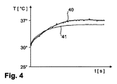
図4は、設定温度が37℃であるホットプレート及び0.30W/mKの熱伝導率を有する皮膚様材料を用いて基礎試験セットアップで得られた温度曲線を示す。第1曲線40は、単一の改良型サーミスタ配置を備えた本発明の改良型単一熱流センサを用いて測定された身体の温度を示す。第2曲線41は、従来の単一熱流センサ(如何なる側方補償も有さない。)を用いて測定された温度を示す。側方サーミスタを使用することの利点が明らかに分かる。これは、改良型サーミスタ配置によって供給される値により推定される温度がより速く平衡に達し、基準温度により類似するものであるからである。
FIG. 4 shows the temperature curves obtained in a basic test setup using a hot plate with a set temperature of 37 ° C. and a skin-like material with a thermal conductivity of 0.30 W / mK. The
図5は、本発明の熱流センサ1の第2実施形態の略断面図を示す。ここで、センサ1は、垂直又は外向き方向における熱伝導抵抗RV、RV1の2つの異なる値を得るよう、下側レイヤ及び上側レイヤを有する。線図は、先に図1で記載されたようなサーミスタS1、S2、S3を備えた改良型サーミスタ構成を、そして、更には、更なる内部サーミスタSV1及び更なる外部サーミスタSV2を有する追加の縦型サーミスタ構成を示す。ここで、サーミスタSV1は、温度測定値TV1を供給し、サーミスタSV2は、温度測定値TV2を供給する。この実施形態では、改良型サーミスタ構成からの温度測定値T1、T2、T3及び追加の縦型サーミスタ構成からの温度測定値TV1、TV2は、評価ユニット2へ送られる。評価ユニット2は、ディスプレイ4を備えた、スマートフォン又はタブレット・コンピュータのような手持ち式デバイスにおいて実現され得る。手持ち式デバイスのマイクロプロセッサ3は、先に記載された式(2)〜(5)を用いて体温Tdbを計算することができる。この例となる実施形態では、センサ1は、評価ユニット2への温度測定値T1、T2、T3、TV1、TV2の無線送信のための無線インターフェイス5を有する。
FIG. 5 shows a schematic sectional view of a second embodiment of the
図6は、中央の縦型サーミスタ構成の周りに4つの改良型サーミスタ構成を備えた改良型デュアルフローセンサ1の下からの平面図を示し、中心に位置付けられた縦型サーミスタ構成の内部サーミスタSV1の位置と、4つの改良型サーミスタ構成の内部サーミスタS1及び側方サーミスタS3の位置とを示す。図7は、改良型デュアルフローセンサ1の中間段の上から平面図を示し、改良型サーミスタ構成の上部サーミスタS2の位置を示す。図8は、改良型デュアルフローセンサ1の最上段の上からの平面図を示し、中心に位置付けられた縦型サーミスタ構成の上部サーミスタSV2の位置を示す。4つの改良型サーミスタ構成によって供給された温度測定値は、検知される体温の正確さを改善するよう平均され得る。
FIG. 6 shows a plan view from below of an improved
図9は、図6〜8の改良型デュアルフローセンサのサーミスタ配置に対応する温度の略図を示す。ここで、様々なサーミスタ配置の相対温度は、マトリクスの影付き領域90、91、92として示されている。影の濃さは、マトリクスの残りの中間色領域に対して解釈される。縦型サーミスタ配置によって測定された温度は、中央の影付き領域90によって示されている。改良型サーミスタ配置の内部サーミスタ及び上部サーミスタによって供給されたデータを用いて測定された温度は、影付き領域92によって示され、一方、改良型サーミスタ配置の内部サーミスタ及び側方サーミスタによって供給されたデータを用いて測定された温度は、影付き領域91によって示されている。図中右上にある影付き領域のより暗い色は、このサーミスタが患者の皮膚と接触不良であることを示す。評価ユニットは、温度測定値におけるそのような相違を特定し、間違った又は信頼できないデータを供給しているように思われるサーミスタ構成からの温度測定値を無視するよう選択され得る。
FIG. 9 shows a schematic diagram of the temperature corresponding to the thermistor arrangement of the improved dual flow sensor of FIGS. Here, the relative temperatures of the various thermistor arrangements are shown as shaded
図10は、先に図9で記載された改良型サーミスタ配置の例となる温度展開プロットを示す。曲線10Aは、内部サーミスタが患者の皮膚と接触良好である3つの改良型サーミスタ配置からの温度測定値に基づき計算された温度の例である。曲線10Bは、内部サーミスタが患者の皮膚と接触不良である第4の改良型サーミスタ配置からの温度測定値に基づき計算された温度の例である。値の持続的な有意な差のために、評価ユニットは、第4の改良型サーミスタ配置によって供給された値を温度計算アルゴリズムから無視しうる。
FIG. 10 shows an exemplary temperature evolution plot of the improved thermistor arrangement described above in FIG.
最終的な推定中核体温は、センサの配置及び熱伝導率に非常に依存する。実験結果は、次善の条件の間でさえ、改良型センサが非常に良く機能することを示している。漸進的に加熱される基準体に適用される場合に、本発明の改良型単一熱流センサによって供給されたデータを用いて検知される温度は、従来の単一熱流センサによって供給されたデータを用いて検知される温度よりもずっと紙一重である。同様に、本発明に従う改良型デュアル熱流センサによって検知される温度は、匹敵する従来のデュアルセンサよりも正確であると認められている。従来のデュアルセンサは、極めて正確であると考えられるが、約0.4℃だけずれている検知温度を報告しうる。これは、特に、予防措置が危機的状況を回避するために講じられ得るように低体温症又は高体温に向かう傾向を識別することが必要である場合に、中核体温に関する有意な相違であると見なされる。 The final estimated core body temperature is highly dependent on sensor placement and thermal conductivity. Experimental results show that the improved sensor performs very well, even during suboptimal conditions. When applied to a progressively heated reference, the temperature sensed using the data provided by the improved single heat flow sensor of the present invention may be less than the data provided by a conventional single heat flow sensor. It is much heavier than the temperature sensed using. Similarly, the temperature sensed by the improved dual heat flow sensor according to the present invention has been found to be more accurate than comparable conventional dual sensors. Conventional dual sensors are considered very accurate, but may report detected temperatures that are off by about 0.4 ° C. This is a significant difference for core body temperature, especially when it is necessary to identify a trend toward hypothermia or hyperthermia so that precautionary measures can be taken to avoid crisis situations. Be considered.
本発明の改良型熱流センサの精度の改善は、横方向の熱流も考慮するからであり、従って、周囲温度の変動に対してそれほど敏感でない。精度の改善は、37.5℃で一定温度の基準体且つ0℃から30℃の周囲又は外部温度の変動について観測されている。本発明の改良型熱流センサによって測定される体温は、周囲温度の全ての値について本質的に一定のままであり、一方、匹敵する従来の熱流センサは、特に、より低い温度で、比較的に不出来を示す。本発明に従う改良型熱流センサは、その従来の対応物よりも有意に上手く機能する。従来の対応物はそうではない。 The improved accuracy of the improved heat flow sensor of the present invention is due to the consideration of lateral heat flow and is therefore less sensitive to ambient temperature variations. Improvements in accuracy have been observed for a reference at a constant temperature of 37.5 ° C and ambient or external temperature variations from 0 ° C to 30 ° C. The body temperature measured by the improved heat flow sensor of the present invention remains essentially constant for all values of ambient temperature, while comparable prior art heat flow sensors are relatively low, especially at lower temperatures. Indicates failure. The improved heat flow sensor according to the present invention performs significantly better than its conventional counterpart. The traditional counterpart is not.
図11は、単一の熱流センサとして実現され、垂直なサーミスタ対S1、S2を有する本発明の受動型熱流センサの更なる実施形態であって、改良型サーミスタ配置の構成を与え、夫々のサーミスタ配置が垂直なサーミスタ対S1、S2及び隣接する垂直なサーミスタ対の下側のサーミスタS1に対応する側方サーミスタを有するものを示す。中核体温を決定するために、サーミスタS1、S2の温度測定値は、最大の垂直熱流を有している対Vmaxを特定するよう調べられる。この垂直なサーミスタ対Vmaxのうち、内部サーミスタS1及び外部サーミスタS2は、上記の式(2)のT1及びT2の値を供給する。T3の値は、サーミスタS1、S2の温度測定値を加算して結果を2で割ることによって、隣接する垂直な対、例えば、“最大垂直束”の対Vmaxの左側にある垂直な対Vleft又は右側にある垂直な対Vright、などを求めることで、決定され得る。最もありそうな結果は、上記の式(2)におけるT3の値として選択され得る。 FIG. 11 is a further embodiment of the passive heat flow sensor of the present invention, implemented as a single heat flow sensor and having a vertical thermistor pair S1, S2, providing an improved thermistor arrangement configuration, wherein each thermistor The arrangement shows a vertical thermistor pair S1, S2 and a side thermistor corresponding to the lower thermistor S1 of an adjacent vertical thermistor pair. To determine the core body temperature, the temperature measurements of the thermistors S1, S2 are examined to identify the pair V max that has the largest vertical heat flow. Of the vertical thermistor pairs V max, the internal thermistor S1 and the external thermistor S2 are supplied the values of T1 and T2 of the above formula (2). The value of T3 is divided by 2 the results by adding the temperature measurement of the thermistor S1, S2, adjacent vertical pair, for example, "maximum vertical flux" vs. perpendicular to the left of the pair V max of V It can be determined by finding left or the vertical pair V right on the right , and so on. The most likely result may be selected as the value of T3 in equation (2) above.
図12は、図11の単一熱流センサの平面図を示し、その接触面11を示す。内部サーミスタS1の位置が示されている。最大の垂直熱流を有しているサーミスタ対Vmaxの位置は、対応する内部サーミスタを取り囲む点線によって示されている。線図は、このサーミスタ対Vmaxが4つのとり得る“隣接物”(2つのそのような対Vleft、Vrightが図11では示された。)を有していることを示し、そのうちのいずれもが先に記載されたようにT3を決定するために使用され得る。複数の隣接するサーミスタを選択することができることの利点は、如何なる間違った温度測定値(例えば、患者の皮膚に対する次善の接触から起こる。)も、先に図9で説明されたように、特定されて無視され得る。
FIG. 12 shows a plan view of the single heat flow sensor of FIG. 11 and shows its
本発明は、好適な実施形態及びその変形の形で開示されてきたが、多数の更なる改良及び変形が、本発明の適用範囲から外れることなしにそれらに対してなされ得ることが理解されるだろう。例えば、如何なる適切なセンサ形状も使用されてよい。同様に、様々な個数の垂直及び側方サーミスタが本発明の改良型熱流センサの種々の実施形態において組み込まれ得る。上述されたように、中核温の計算は、センサで行われ得る、あるいは、遠隔で行われ得る。結果は、その場で(スクリーンに)、あるいは、遠隔でスマート・ウォッチ、携帯電話機又はその他適切なデバイスのディスプレイに表示され得る。更には、本発明の原理は、例えば、センサを零熱流束状態に至らせるよう加熱要素を制御することによって、能動型センサの実現化において使用され得る。 Although the present invention has been disclosed in terms of preferred embodiments and variations thereof, it will be understood that many further modifications and variations may be made thereto without departing from the scope of the invention. right. For example, any suitable sensor shape may be used. Similarly, various numbers of vertical and side thermistors may be incorporated in various embodiments of the improved heat flow sensor of the present invention. As described above, the calculation of the core temperature may be performed at the sensor or may be performed remotely. The results can be displayed on the spot (on the screen) or remotely on the display of a smart watch, mobile phone or other suitable device. Furthermore, the principles of the present invention may be used in the implementation of an active sensor, for example, by controlling a heating element to bring the sensor to a zero heat flux state.
明りょうさのために、本願の全体を通した“1つの(a又はan)”の使用は、複数個を除外せず、“有する(comprising)”は、他のステップ又は要素を除外しない点が理解されるべきである。“ユニット”又は“モジュール”の言及は、1つよりも多いユニット又はモジュールの使用を排除しない。 For the sake of clarity, the use of "a" or "an" throughout this application does not exclude a plurality and "comprising" does not exclude other steps or elements. Should be understood. Reference to "unit" or "module" does not exclude the use of more than one unit or module.
1 熱流センサ
2 評価ユニット
3 マイクロプロセッサ
4 ディスプレイ
5 無線インターフェイス
8 対象
10 温度検知配置
11 センサ接触面
12 センサ外面
10A、10B 温度曲線
40、41 温度曲線
90、91、92 マトリクス場
110、111 温度曲線
120、121 温度曲線
130、131、132 温度曲線
140、141 温度曲線
RB 身体抵抗
RV、RV1、RH 熱伝導抵抗
S1、SV1 内部サーミスタ
S2、SV2 上部サーミスタ
S3 側方サーミスタ
Tdb 中核体温
T1、T2、T3 温度測定値
TV1、TV2 温度測定値
Vmax サーミスタ対
Vleft、Vright サーミスタ対
DESCRIPTION OF
Claims (14)
温度監視プロシージャの間に対象に置かれる接触面と、
下側レイヤと、
上側レイヤと、
当該センサの前記下側レイヤの内面に配置される内部サーミスタ、及び当該センサの前記上側レイヤの上面に配置される上部サーミスタを有する縦型サーミスタ配置と、
複数の複合サーミスタ配置と
を有し、
複合サーミスタ配置は、
当該センサの前記下側レイヤの内面に配置される内部サーミスタと、
当該センサの前記下側レイヤの上面に配置され、前記対象から外へ向かう垂直な熱流を測定するよう前記複合サーミスタ配置の内部サーミスタに対して配置される上部サーミスタと、
前記接触面に沿って水平な熱流を測定するよう前記複合サーミスタ配置の内部サーミスタと列をなして配置される側方サーミスタと
を有する、
前記受動型デュアル熱流センサ。 A passive dual heat flow sensor,
A contact surface placed on the subject during the temperature monitoring procedure;
The lower layer,
An upper layer,
An internal thermistor disposed on the inner surface of the lower layer of the sensor, and a vertical thermistor arrangement having an upper thermistor disposed on the upper surface of the upper layer of the sensor;
And a plurality of composite thermistor arrangements,
The composite thermistor arrangement is
An internal thermistor disposed on the inner surface of the lower layer of the sensor,
An upper thermistor disposed on the upper surface of the lower layer of the sensor and disposed relative to an internal thermistor of the composite thermistor arrangement to measure a vertical heat flow out of the object;
Having a side thermistor arranged in line with the internal thermistor of the composite thermistor arrangement to measure horizontal heat flow along the contact surface;
The passive dual heat flow sensor.
請求項1に記載の受動型デュアル熱流センサ。 The passive dual heat flow sensor according to claim 1, comprising at least four composite thermistor arrangements.
垂直なサーミスタ対は、内部サーミスタ及び上部サーミスタを有する、
請求項1又は2に記載の受動型デュアル熱流センサ。 Having a plurality of vertical thermistor pairs,
A vertical thermistor pair having an internal thermistor and an upper thermistor;
The passive dual heat flow sensor according to claim 1.
請求項1乃至3のうちいずれか一項に記載の受動型デュアル熱流センサ。 The outer surface of the sensor is exposed,
The passive dual heat flow sensor according to claim 1.
請求項1に記載の受動型デュアル熱流センサ。 The vertical thermistor arrangement is centered in the heat flow sensor;
The passive dual heat flow sensor according to claim 1.
当該方法は、
温度監視プロシージャの間に前記対象に前記受動型デュアル熱流センサの接触面を置くステップと、
前記受動型デュアル熱流センサのサーミスタによって収集された温度測定値を受け取るステップと、
前記受け取られた温度測定値に基づいて前記対象の温度を計算するステップと
を有する、
方法。 A method for measuring a temperature of an object by the passive dual heat flow sensor according to any one of claims 1 to 5,
The method is
Placing a contact surface of the passive dual heat flow sensor on the object during a temperature monitoring procedure;
Receiving temperature measurements collected by the passive dual heat flow sensor thermistor;
Calculating the temperature of the subject based on the received temperature measurements.
Method.
隣接する複合サーミスタを特定するステップと、
前記隣接する複合サーミスタの温度測定値に基づき前記対象の温度を計算するステップと
を有する
請求項6に記載の方法。 Comparing temperature measurements of the composite thermistor arrangement of the passive dual heat flow sensor to identify a thermistor associated with a maximum vertical heat flow;
Identifying adjacent compound thermistors;
Calculating the temperature of the object based on a temperature measurement of the adjacent composite thermistor.
請求項6又は7に記載の方法。 The method according to claim 6 or 7, comprising averaging one or more temperature measurements before calculating the temperature of the object.
信頼できない温度測定値を提供する複合サーミスタ配置を特定するステップと、
前記信頼できない温度測定値を提供する複合サーミスタ配置によって収集された温度測定値を捨てるステップと
を有する
請求項6乃至8のうちいずれか一項に記載の方法。 Comparing temperature measurements of the composite thermistor arrangement of the passive dual heat flow sensor;
Identifying a composite thermistor arrangement that provides unreliable temperature readings;
Discarding the temperature measurements collected by the composite thermistor arrangement that provides said unreliable temperature measurements.
請求項1乃至5のうちいずれか一項に記載の受動型デュアル熱流センサと、
前記受動型デュアル熱流センサのサーミスタから温度測定値を受け取り、該受け取られた温度測定値に基づいて前記対象の温度を計算するよう配置される評価ユニットと
を有する前記温度検知配置。 A temperature detection arrangement for monitoring the temperature of the object,
A passive dual heat flow sensor according to any one of claims 1 to 5,
An evaluation unit arranged to receive a temperature measurement from the thermistor of the passive dual heat flow sensor and calculate the temperature of the object based on the received temperature measurement.
請求項10に記載の温度検知配置。 The passive dual heat flow sensor has a wireless interface for transmitting a temperature measurement to the evaluation unit.
A temperature sensing arrangement according to claim 10.
請求項10又は11に記載の温度検知配置。 The passive dual heat flow sensor is implemented as a wireless device,
A temperature sensing arrangement according to claim 10.
請求項10乃至12のうちいずれか一項に記載の温度検知配置。 The evaluation unit is implemented as a portable device;
A temperature sensing arrangement according to any one of claims 10 to 12.
請求項10乃至13のうちいずれか一項に記載の温度検知配置。 A temperature sensing arrangement according to any one of claims 10 to 13, which is incorporated into a patient support device.
Applications Claiming Priority (3)
| Application Number | Priority Date | Filing Date | Title |
|---|---|---|---|
| EP15201450 | 2015-12-21 | ||
| EP15201450.2 | 2015-12-21 | ||
| PCT/EP2016/082200 WO2017108964A1 (en) | 2015-12-21 | 2016-12-21 | Heat-flow sensor |
Publications (3)
| Publication Number | Publication Date |
|---|---|
| JP2019501389A JP2019501389A (en) | 2019-01-17 |
| JP2019501389A5 JP2019501389A5 (en) | 2019-10-03 |
| JP6666446B2 true JP6666446B2 (en) | 2020-03-13 |
Family
ID=55027381
Family Applications (1)
| Application Number | Title | Priority Date | Filing Date |
|---|---|---|---|
| JP2018532172A Active JP6666446B2 (en) | 2015-12-21 | 2016-12-21 | Heat flow sensor |
Country Status (7)
| Country | Link |
|---|---|
| US (1) | US10866147B2 (en) |
| EP (1) | EP3394580B1 (en) |
| JP (1) | JP6666446B2 (en) |
| CN (1) | CN108431564B (en) |
| BR (1) | BR112018012423A2 (en) |
| RU (1) | RU2018126837A (en) |
| WO (1) | WO2017108964A1 (en) |
Families Citing this family (19)
| Publication number | Priority date | Publication date | Assignee | Title |
|---|---|---|---|---|
| CN113367671A (en) | 2015-08-31 | 2021-09-10 | 梅西莫股份有限公司 | Wireless patient monitoring system and method |
| WO2018229581A1 (en) | 2017-06-11 | 2018-12-20 | Kenzen Ag | Chip-based multi-channel electrochemical transducer and method of use thereof |
| WO2019133601A1 (en) * | 2017-12-28 | 2019-07-04 | Robert Bosch Gmbh | Body core temperature sensor with two tegs |
| JP7073940B2 (en) * | 2018-06-27 | 2022-05-24 | 日本電信電話株式会社 | In-vivo temperature measuring device and in-vivo temperature measuring method |
| US11534568B2 (en) | 2018-06-28 | 2022-12-27 | Koninklijke Philips N.V. | Pressure support system and method of providing pressure support therapy to a patient |
| JP7149575B2 (en) * | 2018-08-10 | 2022-10-07 | 株式会社Msd | Vital information collection system and program |
| EP3666179A1 (en) * | 2018-12-11 | 2020-06-17 | Koninklijke Philips N.V. | Core body temperature sensor system based on flux measurement |
| CN109632144B (en) * | 2019-01-22 | 2023-08-22 | 浙江大学 | Measuring probe for determining temperature of biological core |
| CN109883571B (en) * | 2019-01-22 | 2021-05-04 | 浙江想能睡眠科技股份有限公司 | Temperature acquisition device for intelligent mattress temperature control detection and acquisition method thereof |
| EP3699570A1 (en) * | 2019-02-19 | 2020-08-26 | Nederlandse Organisatie voor toegepast- natuurwetenschappelijk onderzoek TNO | Core body temperature sensor and method for the manufacturing thereof |
| US20200329993A1 (en) | 2019-04-17 | 2020-10-22 | Masimo Corporation | Electrocardiogram device |
| USD985498S1 (en) | 2019-08-16 | 2023-05-09 | Masimo Corporation | Connector |
| USD917704S1 (en) | 2019-08-16 | 2021-04-27 | Masimo Corporation | Patient monitor |
| USD919094S1 (en) | 2019-08-16 | 2021-05-11 | Masimo Corporation | Blood pressure device |
| USD927699S1 (en) | 2019-10-18 | 2021-08-10 | Masimo Corporation | Electrode pad |
| CN111141420A (en) * | 2020-02-04 | 2020-05-12 | 上海申矽凌微电子科技有限公司 | Object deep temperature measuring method and device based on heat flow method |
| USD933232S1 (en) | 2020-05-11 | 2021-10-12 | Masimo Corporation | Blood pressure monitor |
| USD979516S1 (en) | 2020-05-11 | 2023-02-28 | Masimo Corporation | Connector |
| WO2021234986A1 (en) * | 2020-05-19 | 2021-11-25 | 拓則 島崎 | Physical condition change detection device and physical condition change management system |
Family Cites Families (22)
| Publication number | Priority date | Publication date | Assignee | Title |
|---|---|---|---|---|
| JPS6358223A (en) * | 1986-08-29 | 1988-03-14 | Tatsuo Togawa | Clinical thermometer device |
| JP3103963B2 (en) * | 1993-12-14 | 2000-10-30 | セイコーインスツルメンツ株式会社 | How to measure thermal conductivity |
| US5711604A (en) | 1993-12-14 | 1998-01-27 | Seiko Instruments Inc. | Method for measuring the coefficient of heat conductivity of a sample |
| FI96066C (en) * | 1994-03-24 | 1996-04-25 | Polar Electro Oy | Method and apparatus for determining the internal temperature and coefficient of heat conduction in a structure |
| JPH08304144A (en) | 1995-05-12 | 1996-11-22 | Idoutai Tsushin Sentan Gijutsu Kenkyusho:Kk | Liquid level gage |
| US6220750B1 (en) * | 1999-03-29 | 2001-04-24 | Yoram Palti | Non-invasive temperature measurement method and apparatus |
| US6735379B2 (en) * | 2000-06-28 | 2004-05-11 | Fisher & Paykel Healthcare Limited | Energy sensor |
| JP4157914B2 (en) * | 2002-03-20 | 2008-10-01 | 坂野 數仁 | Temperature measuring apparatus and temperature measuring method |
| JP4600170B2 (en) * | 2004-09-15 | 2010-12-15 | セイコーエプソン株式会社 | Thermometer and electronic device having thermometer |
| DE102005004933B3 (en) * | 2005-02-03 | 2006-08-31 | Dräger Safety AG & Co. KGaA | Device for measuring the body temperature of a living being |
| JP2006280762A (en) * | 2005-04-04 | 2006-10-19 | Anet Corporation | Life condition recorder apparatus and body information processing system |
| JP2007315917A (en) * | 2006-05-25 | 2007-12-06 | Terumo Corp | Apparatus for measuring deep temperature and external communication device |
| KR20090097153A (en) * | 2006-12-06 | 2009-09-15 | 코닌클리케 필립스 일렉트로닉스 엔.브이. | Device for measuring core temperature |
| DE102008026642B4 (en) * | 2008-06-03 | 2010-06-10 | Dräger Medical AG & Co. KG | Double temperature sensor with a receiving element |
| CN102348967B (en) | 2009-03-13 | 2014-06-04 | 皇家飞利浦电子股份有限公司 | Zero heat flux temperature sensing device |
| WO2010116297A1 (en) * | 2009-04-06 | 2010-10-14 | Koninklijke Philips Electronics N.V. | A temperature sensor for body temperature measurement |
| ES2710276T3 (en) | 2009-07-27 | 2019-04-24 | Csem Ct Suisse Delectronique Microtechnique Sa Rech Developpement | Sensor and method to determine the core body temperature |
| JP5648283B2 (en) | 2009-12-24 | 2015-01-07 | セイコーエプソン株式会社 | Electronic thermometer and body temperature measuring method |
| JP5578029B2 (en) | 2010-10-29 | 2014-08-27 | セイコーエプソン株式会社 | Temperature measuring apparatus and temperature measuring method |
| JP2012112767A (en) | 2010-11-24 | 2012-06-14 | Citizen Holdings Co Ltd | Temperature measuring device |
| US8657758B2 (en) | 2010-12-02 | 2014-02-25 | Welch Allyn, Inc. | Devices and methods for temperature determination |
| WO2013121762A1 (en) | 2012-02-14 | 2013-08-22 | テルモ株式会社 | Clinical thermometer and body temperature measurement system |
-
2016
- 2016-12-21 CN CN201680075191.5A patent/CN108431564B/en active Active
- 2016-12-21 JP JP2018532172A patent/JP6666446B2/en active Active
- 2016-12-21 RU RU2018126837A patent/RU2018126837A/en not_active Application Discontinuation
- 2016-12-21 BR BR112018012423A patent/BR112018012423A2/en not_active Application Discontinuation
- 2016-12-21 EP EP16826324.2A patent/EP3394580B1/en active Active
- 2016-12-21 US US15/781,867 patent/US10866147B2/en active Active
- 2016-12-21 WO PCT/EP2016/082200 patent/WO2017108964A1/en active Application Filing
Also Published As
| Publication number | Publication date |
|---|---|
| RU2018126837A (en) | 2020-01-23 |
| EP3394580A1 (en) | 2018-10-31 |
| EP3394580B1 (en) | 2019-11-27 |
| WO2017108964A1 (en) | 2017-06-29 |
| JP2019501389A (en) | 2019-01-17 |
| CN108431564B (en) | 2021-04-23 |
| BR112018012423A2 (en) | 2018-12-18 |
| US20180364109A1 (en) | 2018-12-20 |
| CN108431564A (en) | 2018-08-21 |
| US10866147B2 (en) | 2020-12-15 |
Similar Documents
| Publication | Publication Date | Title |
|---|---|---|
| JP6666446B2 (en) | Heat flow sensor | |
| JP7005513B2 (en) | Single heat flux sensor device | |
| US10827931B2 (en) | Patch for temperature determination | |
| US7625117B2 (en) | Bandage with sensors | |
| CA2583034C (en) | Bandage with sensors | |
| CN108431566B (en) | Method for predicting stable temperature of heat flow sensor | |
| AU2018223205B2 (en) | Temperature sensor | |
| JP2019097819A (en) | Biological data measuring apparatus | |
| CN111837019B (en) | Biological data measuring device | |
| US20220000370A1 (en) | Core body temperature sensor system based on flux measurement | |
| EP3699570A1 (en) | Core body temperature sensor and method for the manufacturing thereof | |
| Saurabh et al. | Continuous core body temperature estimation via SURFACE temperature measurements using wearable sensors-is it feasible? | |
| Anuar et al. | Non-invasive core body temperature sensor for continuous monitoring | |
| KR20140121183A (en) | Single layer thermometer for noninvasive and nonintrusive deep body temperature monitoring | |
| Atallah et al. | Perioperative measurement of core body temperature using an unobtrusive passive heat flow sensor | |
| Sekiguchi et al. | Monitoring internal body temperature | |
| Finvers et al. | Wireless temporal artery bandage thermometer | |
| KR102454112B1 (en) | Angiocatheter Mounted with Temperature Sensor | |
| Kramme et al. | Temperature Monitoring | |
| Kyriacou | Biomedical Sensors | |
| BG2970U1 (en) | Device for non-invasive observation of the body temperature and respiration |
Legal Events
| Date | Code | Title | Description |
|---|---|---|---|
| A521 | Request for written amendment filed |
Free format text: JAPANESE INTERMEDIATE CODE: A523 Effective date: 20180622 |
|
| A521 | Request for written amendment filed |
Free format text: JAPANESE INTERMEDIATE CODE: A523 Effective date: 20190819 |
|
| A621 | Written request for application examination |
Free format text: JAPANESE INTERMEDIATE CODE: A621 Effective date: 20190819 |
|
| A871 | Explanation of circumstances concerning accelerated examination |
Free format text: JAPANESE INTERMEDIATE CODE: A871 Effective date: 20190819 |
|
| A975 | Report on accelerated examination |
Free format text: JAPANESE INTERMEDIATE CODE: A971005 Effective date: 20190918 |
|
| A131 | Notification of reasons for refusal |
Free format text: JAPANESE INTERMEDIATE CODE: A131 Effective date: 20191105 |
|
| A521 | Request for written amendment filed |
Free format text: JAPANESE INTERMEDIATE CODE: A523 Effective date: 20191114 |
|
| TRDD | Decision of grant or rejection written | ||
| A01 | Written decision to grant a patent or to grant a registration (utility model) |
Free format text: JAPANESE INTERMEDIATE CODE: A01 Effective date: 20200128 |
|
| A61 | First payment of annual fees (during grant procedure) |
Free format text: JAPANESE INTERMEDIATE CODE: A61 Effective date: 20200220 |
|
| R150 | Certificate of patent or registration of utility model |
Ref document number: 6666446 Country of ref document: JP Free format text: JAPANESE INTERMEDIATE CODE: R150 |
|
| R250 | Receipt of annual fees |
Free format text: JAPANESE INTERMEDIATE CODE: R250 |
|
| R250 | Receipt of annual fees |
Free format text: JAPANESE INTERMEDIATE CODE: R250 |