JP6657896B2 - Method of manufacturing male shaft for telescopic shaft - Google Patents
Method of manufacturing male shaft for telescopic shaft Download PDFInfo
- Publication number
- JP6657896B2 JP6657896B2 JP2015241093A JP2015241093A JP6657896B2 JP 6657896 B2 JP6657896 B2 JP 6657896B2 JP 2015241093 A JP2015241093 A JP 2015241093A JP 2015241093 A JP2015241093 A JP 2015241093A JP 6657896 B2 JP6657896 B2 JP 6657896B2
- Authority
- JP
- Japan
- Prior art keywords
- shaft
- diameter
- axial
- axial direction
- male
- Prior art date
- Legal status (The legal status is an assumption and is not a legal conclusion. Google has not performed a legal analysis and makes no representation as to the accuracy of the status listed.)
- Active
Links
- 238000004519 manufacturing process Methods 0.000 title claims description 33
- 230000002093 peripheral effect Effects 0.000 claims description 66
- 239000000463 material Substances 0.000 claims description 61
- 239000011247 coating layer Substances 0.000 claims description 24
- 238000000034 method Methods 0.000 claims description 17
- 230000008859 change Effects 0.000 claims description 7
- 239000007787 solid Substances 0.000 claims description 4
- 230000007423 decrease Effects 0.000 claims description 3
- 239000007769 metal material Substances 0.000 claims description 3
- 238000005520 cutting process Methods 0.000 description 20
- 230000008569 process Effects 0.000 description 8
- 238000001125 extrusion Methods 0.000 description 4
- 230000009467 reduction Effects 0.000 description 4
- 238000005096 rolling process Methods 0.000 description 4
- 229920003002 synthetic resin Polymers 0.000 description 4
- 239000000057 synthetic resin Substances 0.000 description 4
- XEEYBQQBJWHFJM-UHFFFAOYSA-N Iron Chemical compound [Fe] XEEYBQQBJWHFJM-UHFFFAOYSA-N 0.000 description 2
- 229910045601 alloy Inorganic materials 0.000 description 2
- 239000000956 alloy Substances 0.000 description 2
- 238000006073 displacement reaction Methods 0.000 description 2
- 238000005553 drilling Methods 0.000 description 2
- 230000007246 mechanism Effects 0.000 description 2
- 238000003825 pressing Methods 0.000 description 2
- 238000003466 welding Methods 0.000 description 2
- 229910000975 Carbon steel Inorganic materials 0.000 description 1
- 229910000861 Mg alloy Inorganic materials 0.000 description 1
- 229910052782 aluminium Inorganic materials 0.000 description 1
- XAGFODPZIPBFFR-UHFFFAOYSA-N aluminium Chemical compound [Al] XAGFODPZIPBFFR-UHFFFAOYSA-N 0.000 description 1
- 238000005452 bending Methods 0.000 description 1
- 230000005540 biological transmission Effects 0.000 description 1
- 230000015572 biosynthetic process Effects 0.000 description 1
- 239000010962 carbon steel Substances 0.000 description 1
- 238000010273 cold forging Methods 0.000 description 1
- 238000007598 dipping method Methods 0.000 description 1
- 230000009977 dual effect Effects 0.000 description 1
- 230000000694 effects Effects 0.000 description 1
- 238000007610 electrostatic coating method Methods 0.000 description 1
- 239000012530 fluid Substances 0.000 description 1
- 238000000227 grinding Methods 0.000 description 1
- 238000007654 immersion Methods 0.000 description 1
- 230000006872 improvement Effects 0.000 description 1
- 238000003780 insertion Methods 0.000 description 1
- 230000037431 insertion Effects 0.000 description 1
- 229910052742 iron Inorganic materials 0.000 description 1
- 229910001234 light alloy Inorganic materials 0.000 description 1
- 230000001105 regulatory effect Effects 0.000 description 1
- 102200082907 rs33918131 Human genes 0.000 description 1
- 102200082816 rs34868397 Human genes 0.000 description 1
- 230000001629 suppression Effects 0.000 description 1
- 230000003746 surface roughness Effects 0.000 description 1
Images


Description
本発明は、例えば自動車の操舵装置を構成する中間シャフトとして使用される伸縮自在シャフトを構成する雄軸の製造方法の改良に関する。 The present invention relates to an improvement in a method for manufacturing a male shaft that constitutes a telescopic shaft used as an intermediate shaft that constitutes, for example, a steering device of an automobile.
自動車のステアリング装置として従来から、図8に記載する様な構造のものが知られている。該ステアリング装置は、ステアリングホイール1が、ステアリングシャフト2の後端部に固定されている。又、これと共に、該ステアリングシャフト2の前端部が、1対の自在継手3a、3b及び中間シャフト4を介して、ステアリングギヤユニット5を構成する入力軸6の基端部に接続されている。更に、前記ステアリングギヤユニット5に内蔵されラックアンドピニオン機構により左右1対のタイロッド7、7を押し引きして、左右1対の操舵輪に、前記ステアリングホイール1の操作量に応じた舵角を付与する様に構成されている。
2. Description of the Related Art Conventionally, an automobile steering device having a structure as shown in FIG. 8 is known. In the steering device, a steering wheel 1 is fixed to a rear end of a
この様なステアリング装置に組み込まれる前記中間シャフト4は、例えば、走行時に自動車から入力される振動が、前記ステアリングホイール1に伝わる事を防止する(吸収する)為、或いは、前記中間シャフト4を、全長を縮めた状態で車体に組み込む為に、伸縮式のものが使用されている。 The intermediate shaft 4 incorporated in such a steering device is used, for example, to prevent (absorb) vibration transmitted from an automobile during transmission to be transmitted to the steering wheel 1 or to provide the intermediate shaft 4 with: In order to incorporate it into the vehicle body with its overall length shortened, a telescopic type is used.
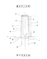
図9は、特許文献1に記載された伸縮式の中間シャフト4の構造を示している。該中間シャフト4は、軸方向一端部(前端部であって、図9の左端部。組み付け状態でアウタチューブ10側の端部)の外周面に雄スプライン部8が形成されたインナシャフト9と、内周面に該雄スプライン部8とスプライン係合可能な雌スプライン部12が形成された円管状のアウタチューブ10とから成る。そして、前記雄スプライン部8と前記雌スプライン部12とをスプライン係合する事で、前記インナシャフト9と前記アウタチューブ10とを、伸縮自在に組み合わせている。
FIG. 9 shows a structure of a telescopic intermediate shaft 4 described in Patent Document 1. The intermediate shaft 4 includes an inner shaft 9 having a male spline portion 8 formed on an outer peripheral surface of one axial end portion (a front end portion, a left end portion in FIG. 9; an end portion on the
又、図9に示す構造の場合、前記インナシャフト9を、後側(前後方向とは、車体の前後方向を言う。本明細書及び特許請求の範囲全体で同じ。)に配置すると共に、前記アウタチューブ10を前側に配置している。又、前記インナシャフト9の軸方向他端部には、前記両自在継手3a、3bのうちの後側に配置された自在継手3aを構成する第一のヨーク11が外嵌固定(圧入)されている。一方、前記アウタチューブ10の軸方向一端部には、前記両自在継手3a、3bのうちの前側に配置された自在継手3bを構成する第二のヨーク13が外嵌固定(圧入)されている。
尚、前記インナシャフト9と前記第一のヨーク11との結合、或いは、前記アウタチューブ10と前記第二のヨーク13との結合は、溶接により行う事もできる。又、後述する実施の形態の構造の様に、インナシャフトを前側に、アウタチューブを後側に配置する構造を採用する事もできる。
In the case of the structure shown in FIG. 9, the inner shaft 9 is disposed on the rear side (the front-rear direction is the front-rear direction of the vehicle body. The same applies throughout the present specification and claims). The
The connection between the inner shaft 9 and the
ところで、従来から前記中間シャフト4を構成するインナシャフト9の軸方向中間部に存在する小径軸部34を、切削加工により形成する事が行われている。具体的には、前記インナシャフト9の基となる中間部材の外径を全長に亙り転造下径に加工した状態、或は、該中間部材の全長に亙り雄スプライン部を形成した状態で、前記小径軸部34に相当する部分に切削加工を施す。この様な切削加工は、面倒であり加工時間が嵩むだけでなく、切削加工の際に生じる切り屑の分だけ材料の歩留まりが悪く、製造コストが嵩んでしまう可能性がある。
By the way, the small-
本発明は、上述の様な事情に鑑みて、製造コストの低減を図る事ができる伸縮自在シャフト用雄軸の製造方法を実現するものである。 SUMMARY OF THE INVENTION The present invention has been made in view of the above-described circumstances, and provides a method of manufacturing a male shaft for a telescopic shaft, which can reduce the manufacturing cost.
本発明の製造方法の対象となる伸縮自在シャフト用雄軸は、雄スプライン部と、小径軸部と、ヨーク部と、中心孔とを有している。
このうちの雄スプライン部は、前記雄軸の軸方向一端部の外周面に形成されている。
前記小径軸部は、中実円柱状に構成され、前記雄スプライン部よりも軸方向他方側に形成されており、外径が該雄スプライン部の各凸部の外接円の直径よりも小さい。
前記ヨーク部は、前記小径軸部の軸方向他端部に一体に設けられている。
前記中心孔は、軸方向一端が前記雄軸の軸方向一端面に開口している。
前記中心孔の軸方向他端縁は、前記雄スプライン部の軸方向に関する長さ寸法をLとした場合に、該雄スプライン部の軸方向一端縁から、(0.5〜1.0)・Lとなる位置に配置されている。
この様な伸縮自在シャフト用雄軸は、前記雄スプライン部を、雌軸の内周面に形成された雌スプライン部に係合させる事により、該雌軸との間でトルク伝達可能、且つ、全長を伸縮可能な状態に組み合わされる。
The male shaft for the telescopic shaft, which is the object of the manufacturing method of the present invention, has a male spline portion, a small-diameter shaft portion, a yoke portion, and a center hole.
Of these, the male spline portion is formed on the outer peripheral surface of one end in the axial direction of the male shaft.
The small-diameter shaft portion is formed in a solid cylindrical shape, is formed on the other axial side of the male spline portion, and has an outer diameter smaller than a diameter of a circumscribed circle of each convex portion of the male spline portion.
The yoke part is provided integrally with the other end in the axial direction of the small diameter shaft part.
One end in the axial direction of the center hole is open at one end surface in the axial direction of the male shaft.
The other end of the center hole in the axial direction is (0.5 to 1.0) · from one end of the male spline in the axial direction, where L is the length in the axial direction of the male spline. L.
Such a male shaft for a telescopic shaft is capable of transmitting torque between the male shaft and the female shaft by engaging the male spline portion with a female spline portion formed on the inner peripheral surface of the female shaft. Combined in a state where the entire length can be expanded and contracted.
特に、本発明の伸縮自在シャフト用雄軸の製造方法に於いては、軸方向一端部から軸方向他端寄り部分にかけての部分に全長に亙り外径が変化しない円柱状の素軸部を有する、第一中間素材を造る工程を有している。
又、前記第一中間素材に孔あけ加工を施す事により、軸方向一端が前記第一中間素材の軸方向一端面に開口し、且つ、内径が、前記中心孔の最大内径よりも小さい円筒部と、軸方向一端縁が、該円筒面部の軸方向他端縁に連続し、且つ、内径が、軸方向他方側に向かうほど小さくなる円錐面部とを有する素中心孔を備える第二中間素材を得る工程を有している。
又、前記第二中間素材の軸方向中間部から軸方向一端部にかけての部分の外径側に、外型を配置し、且つ、前記素中心孔の内径側に、軸方向他側面が部分球面状であるマンドレルの扱き部を挿入する事で、前記第二中間素材のうちの前記素中心孔の周囲に存在する部分を構成する金属材料の外径側への流動を、前記外型の内周面により規制し、軸方向他方側へと流動し易くして、前記第二中間素材のうち、前記扱き部よりも軸方向他方側部分の外周面を拡径し易くした状態で、前記扱き部の軸方向他側面の外径寄り部分及び外周面により、前記素中心孔の内周面を扱きながら、前記扱き部が、前記素中心孔のうちの前記円筒面部の軸方向他端部に位置するまで、前記扱き部を軸方向他方側へ変位させる事に伴って、前記素中心孔の内径を拡径して前記中心孔を形成すると同時に、前記第二中間素材のうち、軸方向一端部から、前記円錐面部の軸方向他端縁と軸方向位置が一致する部分又は前記円錐面部の軸方向他端縁よりも軸方向他方側に位置する部分にかけての部分の外径を拡径する、拡径工程を有している。
更に、前記拡径部の外周面に、前記雄スプライン部を形成する、スプライン形成工程を有している。
そして、前記素軸部のうちの前記拡径部を除いた部分の少なくとも一部をそのまま前記小径軸部とする。
尚、上述の各工程は、矛盾が生じない範囲で、順番を入れ替える事が可能である。又、これら各工程は、可能な範囲で、同時に行う事もできる。
In particular, in the method for manufacturing a male shaft for a telescopic shaft according to the present invention, a portion from one axial end to a portion closer to the other axial end has a cylindrical elemental shaft portion whose outer diameter does not change over the entire length. And a step of producing a first intermediate material.
Further, the by performing boring the first intermediate material, one axial end is open in the one axial end surface of the first intermediate material, and an inner diameter, smaller cylindrical portion than the maximum inner diameter of the center hole And a second intermediate material having an elemental central hole having an axial one end edge continuous with the axial other end edge of the cylindrical surface portion, and having a conical surface portion whose inner diameter decreases toward the other axial side. Obtaining step.
Also, an outer die is disposed on the outer diameter side of a portion from the axial middle portion to the one axial end portion of the second intermediate material, and the other axial side surface is partially spherical on the inner diameter side of the element center hole. By inserting a handle portion of a mandrel in a shape of a circle, the flow of the metal material constituting the portion of the second intermediate material that is present around the element center hole to the outer diameter side is reduced inside the outer mold. In the state where the outer peripheral surface of the second intermediate material is more easily expanded toward the other side in the axial direction than the handle portion, the handle is controlled by the circumferential surface to facilitate the flow to the other side in the axial direction. While handling the inner peripheral surface of the element center hole by the outer diameter portion and the outer peripheral surface of the other axial side surface of the portion, the handling portion is attached to the other axial end of the cylindrical surface portion of the element center hole. until the position, along with that to displace the squeezing unit to the other axial side, enlarged the inner diameter of the element center hole At the same time forms the central hole Te, said one of the second intermediate material, from one axial end, the other axial end edge of said portion or the conical surface portion other axial end edge and the axial position of the conical surface coincides expanding the diameter of the outer diameter of the portion ranging portion located on the other side in the axial direction than has the diameter expansion step.
Further, the method includes a spline forming step of forming the male spline portion on the outer peripheral surface of the enlarged diameter portion.
Then, at least a part of the element shaft portion excluding the enlarged diameter portion is used as the small diameter shaft portion as it is.
Note that the order of the above steps can be changed within a range that does not cause inconsistency. Each of these steps can be performed simultaneously to the extent possible.
上述の様な本発明の伸縮自在シャフト用雄軸の製造方法を実施する場合には、前記外型として、円筒面状の内周面を有するものを使用する事ができる。この場合、前記中心孔の内側にサポート軸を挿入した状態で、前記拡径工程において外径が拡径された部分の外周面に雄スプライン部を形成する構成を採用できる。
或いは、前記外型として、内周面に雌スプライン部が形成されたものを使用する事により、前記拡径工程と前記スプライン形成工程とを同時に行う事ができる。
When the method of manufacturing a male shaft for a telescopic shaft according to the present invention as described above is carried out, the outer die having a cylindrical inner peripheral surface can be used. In this case, it is possible to adopt a configuration in which a male spline portion is formed on the outer peripheral surface of the portion whose outer diameter has been increased in the diameter increasing step in a state where the support shaft is inserted inside the center hole.
Alternatively, by using the outer mold having a female spline portion formed on the inner peripheral surface, the diameter increasing step and the spline forming step can be performed simultaneously.
上述の様な本発明の伸縮自在シャフト用雄軸の製造方法を実施する場合には、具体的に、前記雄スプライン部を形成する際、前記雄スプライン部の各凹部の外接円の直径を、前記素軸部の外径よりも大きくする構成を採用できる。 When carrying out the method of manufacturing a telescopic male-axis shaft of the aforementioned such invention, specifically, before the time of forming the Kieu spline portion, the diameter of the circumscribed circle of each concave portion of the male spline portion A configuration in which the outer diameter of the element shaft portion is larger than that of the element shaft portion can be adopted.
上述の様な本発明の伸縮自在シャフト用雄軸の製造方法を実施する場合には、追加的に、前記中心孔の開口部を塞いだ状態で、前記雄スプライン部の外周面に、コーティング層を形成する事ができる。 When carrying out the method of manufacturing a telescopic shaft for the male shaft of the aforementioned such invention, additionally, in a state that closes the opening of the front Symbol center hole, an outer peripheral surface of the male spline portion, the coating Layers can be formed.
上述した様な構成を有する本発明の伸縮自在シャフト用雄軸の製造方法の場合、雄スプライン部を形成する部分である拡径部を、第一中間素材のうちの素中心孔が形成された部分の外径を拡径する事により造っている。即ち、本発明の場合、小径軸部に相当する部分と、前記拡径部に相当する部分との様に、外径寸法が異なる部分を、切削加工を施す事なく造る事ができる。従って、前述した従来の製造方法が採用している、小径軸部を形成する為の切削加工が不要となり、製造コストの低減を図れる。 In the case of the method for manufacturing a male shaft for a telescopic shaft according to the present invention having the above-described configuration, the enlarged diameter portion, which is a portion forming the male spline portion, is formed with the elemental center hole of the first intermediate material. It is made by expanding the outer diameter of the part. That is, in the case of the present invention, portions having different outer diameters, such as a portion corresponding to the small-diameter shaft portion and a portion corresponding to the enlarged-diameter portion, can be manufactured without cutting. Therefore, the cutting process for forming the small-diameter shaft portion, which is employed in the above-described conventional manufacturing method, becomes unnecessary, and the manufacturing cost can be reduced.
[実施の形態の1例]
本発明の実施の形態の1例に就いて、図1〜7により説明する。尚、本例は、本発明の製造方法の対象である伸縮自在シャフト用雄軸を雌軸と組み合わせて、ステアリング装置を構成する中間シャフトに適用したものである。但し、本発明の製造方法の対象である伸縮自在シャフト用雄軸は、この様な中間シャフト以外にも、各種用途で使用される伸縮自在シャフトに使用する事ができる。又、本例の中間シャフトを組み込んだステアリング装置の構造は、図8に示したステアリング装置とほぼ同様の構造を有している。但し、本例の中間シャフト4aは、図8に示したステアリング装置の構造に限らず、従来から知られている各種ステアリング装置の構造に適用する事ができる。以下、本例の中間シャフト4aを組み込む事ができるステアリング装置の構造を簡単に説明した後、本例の中間シャフト4aの構造、及び該中間シャフト4aの製造方法に就いて説明する。
[One Example of Embodiment]
An example of an embodiment of the present invention will be described with reference to FIGS. In this example, a male shaft for a telescopic shaft, which is a subject of the manufacturing method of the present invention, is combined with a female shaft and applied to an intermediate shaft constituting a steering device. However, the male shaft for a telescopic shaft, which is the object of the production method of the present invention, can be used for a telescopic shaft used for various applications other than such an intermediate shaft. The structure of the steering device incorporating the intermediate shaft according to the present embodiment has substantially the same structure as the steering device shown in FIG. However, the
本例の中間シャフト4aを組み込んだステアリング装置は、ステアリングホイール1(図8参照)が、ステアリングシャフト2の後端部に固定されている。又、これと共に、該ステアリングシャフト2の前端部が、1対の自在継手3c、3d及び前記中間シャフト4aを介して、ステアリングギヤユニット5を構成する入力軸6の基端部に接続されている。更に、該ステアリングギヤユニット5に内蔵したラックアンドピニオン機構により左右1対のタイロッド7、7を押し引きして、左右1対の操舵輪に、前記ステアリングホイール1の操作量に応じた舵角を付与する様に構成されている。
In the steering device incorporating the
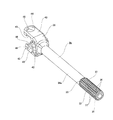
前記中間シャフト4aは、特許請求の範囲に記載した雄軸の1例に相当するインナシャフト9aの軸方向一端部(図1の右端部であって、組み付け状態に於いて、アウタチューブ10a側となる端部)と、同じく雌軸の1例に相当するアウタチューブ10aの軸方向他端部(図1の左端部であって、組み付け状態に於いて、インナシャフト9a側となる端部)とをスプライン係合させる事により、トルク伝達可能、且つ全長を伸縮可能に組み合わせている。以下、前記中間シャフト4aの具体的な構造に就いて説明する。
The
前記アウタチューブ10aは、軸方向他方側から順に、小径筒部18と、連続部19と、大径筒部20と、ヨーク部21とを備えている。
このうちの小径筒部18は円筒状であり、前記アウタチューブ10aのうちの、軸方向他端部から軸方向中央部にかけての部分に設けられている。この様な小径筒部18の外周面は、軸方向の全長に亙り外径寸法が変化しない円筒面状である。又、該小径筒部18の内周面には、円周方向に関して交互に形成された軸方向に長い、複数ずつの凹部と凸部とから成る雌スプライン部22が、全長に亙り形成されている。
The
The small-diameter
前記連続部19は、外径寸法及び内径寸法が軸方向一方側(図1の右側)に向かうほど大きくなる部分円錐筒状であり、軸方向他端縁が、前記小径筒部18の軸方向一端縁に連続している。
前記大径筒部20は円筒状であり、軸方向他端縁が、前記連続部19の軸方向一端縁に連続している。この様な大径筒部20の内径寸法及び外径寸法は、前記小径筒部18の内径寸法及び外径寸法よりも大きい。
The
The large-diameter
前記ヨーク部21は、前記自在継手3cを構成するものであり、前記大径筒部20の軸方向一端縁のうちで、該大径筒部20に関する直径方向反対側となる2箇所位置から軸方向一方側に延出する状態で設けられた1対の腕部23、23から成る。この様な両腕部23、23の軸方向一端寄り部分には、互いの中心軸が同軸となる状態で1対の円孔24、24が形成されている。尚、図1に示す組み立て状態に於いて、該両円孔24、24の内側には、それぞれ有底円筒状の軸受カップ25、25が内嵌固定されている。これと共に、該両軸受カップ25、25の内側に、それぞれ複数本のニードル26、26を介して、十字軸27を構成する4本の軸部28、28のうちの1対の軸部28、28の端部が回動自在に支持されている。
The
尚、前記十字軸27を構成する4本の軸部28、28のうち、前記ヨーク部21の両円孔24、24内に支持された軸部28、28以外の1対の軸部28(一方の軸部28は図示省略)の端部は、前記ステアリングシャフト2の前端部に支持固定されたヨーク29を構成する1対の腕部30(片方の腕部30は図示省略)に形成された円孔(図示省略)の内側に、軸受カップ及びニードル(図示省略)を介して回動自在に支持されている。
本例の場合、前記ヨーク部21を、前記アウタチューブ10aに一体に設ける構造を採用しているが、アウタチューブとヨーク部とを別体に設けて溶接或は嵌合等により結合固定する構造を採用する事もできる。
Note that, of the four
In the case of this example, a structure in which the
前記インナシャフト9aは、軸方向一方側(図1〜3の右側)から順に、予備軸部31、スプライン形成部32と、連続部33と、小径軸部34aと、ヨーク部35とを備えている。
このうちの予備軸部31は、前記インナシャフト9aの軸方向一端部に設けられている。この様な予備軸部31の外周面は、軸方向一端縁に形成された面取り部を除いて、軸方向の全長に亙り変化しない円筒面状に形成されている。
The
The
前記スプライン形成部32は、前記インナシャフト9aの軸方向中間部から軸方向一端寄り部分にかけての部分(軸方向中間部のうちの軸方向一方側部分)に形成されている。この様なスプライン形成部32の軸方向一端縁は、前記予備軸部31の軸方向他端縁(図1の左端縁)に連続している。又、前記スプライン形成部32の外周面には、円周方向に関して交互に形成された軸方向に長い、複数ずつの凹部77と凸部36とから成る雄スプライン部37が、全長に亙り形成されている。
The
前記連続部33は、前記インナシャフト9aのうち、前記スプライン形成部32の軸方向他方側に隣接した部分に形成されている。この様な連続部33の外周面には、円周方向に関して交互に形成された、複数ずつの凹部(図示省略)と、前記インナシャフト9aの中心軸を含む仮想平面に関する断面形状が直角三角形状の凸部38とから成る不完全スプライン部39が形成されている。この様な不完全スプライン部39を構成する各凸部38の外周面は、軸方向他方に向かうほど外径寸法が小さくなる方向に傾斜している。又、前記不完全スプライン部39の各凸部38の外周面の軸方向一端縁は、前記雄スプライン部37を構成する各凸部36の外周面の軸方向他端縁に連続している。一方、前記不完全スプライン部39の各凸部38の外周面の軸方向他端縁は、前記小径軸部34aの外周面の軸方向一端縁に連続している。尚、本例の場合、前記雄スプライン部37の凹部77の外接円の直径と、前記不完全スプライン部39の凹部の外接円の直径とが等しい。
The
前記小径軸部34aは、前記インナシャフト9aのうち、前記連続部33の軸方向他方側に隣接した位置から、軸方向他端寄り部分にかけて形成されている。この様な小径軸部34aの軸方向一端縁は、前記連続部33の軸方向他端縁に連続している。そして、前記小径軸部34aの外径寸法は、前記雄スプライン部37を構成する凹部77及び凸部36の外接円の直径、及び、前記不完全スプライン部39を構成する凹部及び凸部38の外接円の直径よりも小さい。又、前記小径軸部34aの外周面は、後述する素材(又は、第一中間素材57のうちの該小径軸部34aに相当する部分)の外周面そのものにより構成されている。別の言い方をすれば、該小径軸部34aの外周面は、切削加工が施されていない。
The small
前記ヨーク部35は、前記小径軸部34aの軸方向他端部に、該小径軸部34aと一体に設けられている。尚、本例の場合、前記ヨーク部35と、十字軸40と、前記入力軸6の基端部に支持固定されたヨーク41とにより、前記両自在継手3c、3dのうちの、前側(図1の左側)に配置された自在継手3dを構成している。
The
この様なヨーク部35は、略矩形板状の基部42と、該基部42の外周面のうち、該基部42の長手方向反対側(図3の上下方向)となる2箇所位置から軸方向他方側に延出した状態で設けられた1対の腕部43、43とから成る。
このうちの基部42は、軸方向片側面の中央部が前記小径軸部34aの軸方向他端面に連続した状態で設けられている。
Such a
The
又、前記両腕部43、43のうち、軸方向に関して前記基部42と反対側端部寄り部分には、互いの中心軸が同軸となる状態で1対の円孔44、44が形成されている。又、前記両腕部43、43の、互いに対向した両側面の短手方向(図4、5の上下方向)両端部には、それぞれ1対の第一の逃げ凹部45、45が形成されている。この様な両第一の逃げ凹部45、45は、ジョイント角度を大きく確保する為のものである。又、前記両腕部43、43の、互いに対向した両側面の先端部(前記基部42と反対側の端部であって、図4、5の左端部)には第二の逃げ凹部46が形成されている。この様な第二の逃げ凹部46は、前記十字軸40を、前記両円孔44、44に組み付ける際、該十字軸40と前記両腕部43、43との干渉を防止する為のものである。
A pair of
又、図1に示す組み立て状態に於いて、前記両腕部43、43の両円孔44、44の内側には、それぞれ有底円筒状の軸受カップ47、47が内嵌固定されている。これと共に、該両軸受カップ47、47の内側に、それぞれ複数本のニードル48、48を介して、前記十字軸40を構成する4本の軸部49、49のうちの1対の軸部49、49の端部が回動自在に支持されている。
In the assembled state shown in FIG. 1, cylindrical bearing cups 47 with bottoms are respectively fitted and fixed inside the
尚、前記十字軸40を構成する4本の軸部49、49のうち、前記ヨーク部35の両円孔44、44内に支持された軸部49、49以外の1対の軸部49(一方の軸部49は図示省略)の端部は、前記ヨーク50を構成する1対の腕部51(一方の腕部51は図示省略)に形成された円孔(図示省略)の内側に、軸受カップ(図示省略)及びニードル(図示省略)を介して回動自在に支持されている。
It should be noted that, of the four
又、本例の場合、前記インナシャフト9aの軸方向一端縁から、前記雄スプライン部37の軸方向他端縁よりも軸方向一方側となる位置にかけて、軸方向一端が前記インナシャフト9a(予備軸部31)の軸方向一端面に開口した中心孔52が形成されている。
具体的には、前記中心孔52は、円筒面部53と、円錐面部54とから成る。
このうちの円筒面部53は、全長に亙り内径寸法が変化しない円筒面状であり、軸方向に関して、前記インナシャフト9a(前記予備軸部31)の軸方向一端縁から前記スプライン形成部32の軸方向他端寄り部分にかけての部分に形成されている。即ち、前記円筒面部53の軸方向他端縁(該円筒面部53と前記円錐面部54との境界)は、前記連続部33の軸方向一端縁(前記雄スプライン部37と該連続部33との境界であって、図2に直線Xで示す位置)よりも軸方向一方側に位置している。尚、後述する本例の製造方法により前記中心孔52を形成する場合には、前記円錐面部54は完全な円錐状に形成されない場合もある。具体的には、前記円錐面部54の径方向外端寄り部分が、後述するマンドレル65の軸方向他側面の径方向外端寄り部分の形状に沿う様な球面状に形成される場合がある。別の言い方をすれば、中心孔が、円筒面部と、円錐面部と、該円筒面部の軸方向他端縁と該円錐面部の径方向外端縁とを連続する球面部とにより構成される場合がある。
In the case of this example, one end in the axial direction extends from one end in the axial direction of the
Specifically, the
The
又、前記円錐面部54は、軸方向一端縁が、前記円筒面部53の軸方向他端縁に連続した状態で形成されている。この様な円錐面部54は、内径寸法が、軸方向他方側に向かうほど小さくなる状態で形成されている。又、本例の場合、前記円錐面部54の軸方向他端縁も、前記連続部33の軸方向一端縁(前記雄スプライン部37と該連続部33との境界であって、図2に直線Xで示す位置)よりも軸方向一方側に位置している。具体的には、前記円錐面部54の軸方向他端縁は、前記スプライン形成部32(前記雄スプライン部37)の軸方向に関する長さ寸法をL32とした場合に、該スプライン形成部32(前記雄スプライン部37)の軸方向一端縁から、(0.5〜1.0)・L32となる位置に配置する。好ましくは、前記円錐面部54の軸方向他端縁を、前記スプライン形成部32(前記雄スプライン部37)の軸方向一端縁から、(0.7〜0.9)・L32となる位置に配置する。
尚、本例の場合、前記インナシャフト9aのうち、前記中心孔52及び前記ヨーク部35の基部42の軸方向他側面の中央部に形成された基準孔55以外の部分は、中実状に形成されている。
The
In the case of the present example, portions of the
又、前記インナシャフト9aを構成する雄スプライン部37の外周面には、滑りやすい(摩擦係数の低い)合成樹脂製のコーティング層56が設けられている。具体的には、本例の場合、該コーティング層56は、前記インナシャフト9aの外周面のうち、前記予備軸部31の軸方向一端縁から前記小径軸部34aの軸方向一端寄り部分(前記連続部33の軸方向他端縁よりも軸方向他方側に位置する部分であって、図2に直線Yで示す位置)にかけての部分に設けられている。尚、前記インナシャフト9a(前記予備軸部31)の軸方向一端面、及び、前記中心孔52の内周面には、前記コーティング層56は設けられていない。
In addition, a
以上の様な構成を有するインナシャフト9aは、前記雄スプライン部37を全長に亙り、前記アウタチューブ10aの雌スプライン部22に、前記コーティング層56を介してスプライン係合させる事により、前記アウタチューブ10aに組み付けられている。この様に組み付けられた状態で、前記雄スプライン部37と前記雌スプライン部22との係合部には、所定量の締め代が設けられている。この様にして、前記インナシャフト9aと前記アウタチューブ10aとは、トルクの伝達を可能、且つ、全長を伸縮可能な状態に組み合わされている。
The
次に、本例の中間シャフト4aを構成するインナシャフト9aの製造方法に就いて、図4〜7を参照しつつ説明する。
先ず、第1工程に於いて、炭素鋼(例えば、S10C〜S45C)等の鉄系合金、或いは、アルミニウム系合金、マグネシウム合金等の軽合金から成る、円杆状(円柱状)の素材(図示省略)に、前方押出し加工、後方押出し加工等の冷間鍛造加工、及び、プレス加工を施して、図4(A)に示す様な第一中間素材57を造る。尚、本例の場合、前記素材は、押し出し成形材又は引き抜き材を所定長さに切断したものにより構成している。
Next, a method of manufacturing the
First, in a first step, a rod-shaped (column-shaped) material (illustrated) made of an iron-based alloy such as carbon steel (for example, S10C to S45C) or a light alloy such as an aluminum-based alloy or a magnesium alloy. (Omitted), cold forging such as forward extrusion and backward extrusion, and press working to produce a first intermediate material 57 as shown in FIG. 4 (A). In the case of the present example, the material is formed by cutting an extruded material or a drawn material into a predetermined length.
上述の様な第一中間素材57は、特許請求の範囲に記載した中間素材に相当する部材であり、軸方向一端部(図4、5の右端部)から軸方向他端寄り部分にかけて設けられた素軸部58と、軸方向他端部に設けられた素ヨーク部59とを備えている。
このうちの素軸部58は、軸方向の全長に亙り外径寸法D58が変化しない中実の円柱状である。この様な素軸部58は、前記素材のうちの該素軸部58に相当する部分に、前述した後方押出し加工を施す事により造られたものである。
The first intermediate material 57 as described above is a member corresponding to the intermediate material described in the claims, and is provided from one end in the axial direction (the right end in FIGS. 4 and 5) to a portion near the other end in the axial direction. Element shaft 58 and an
Raw axis portion of this 58 is a solid cylindrical shape overall length over the outside diameter D 58 in the axial direction does not change. Such a raw shaft portion 58 is formed by subjecting a portion of the material corresponding to the raw shaft portion 58 to the above-described backward extrusion.
又、前記素ヨーク部59は、前記第一中間素材57の軸方向他端部に、前述の前方押出し加工及びプレス加工により形成されたもので、略円板状の基部42と、1対の素腕部60(片方の素腕部60は図示省略)とから成る。該両素腕部60は、前記基部42の外周面のうち、該基部42の直径方向反対側となる2箇所位置から軸方向他方側に延出する状態で設けられている。又、前記両素腕部60の互いに対向した両側面の短手方向(図4、5の上下方向)端部には、それぞれ1対の第一の逃げ凹部45、45が形成されている。又、前記両素腕部60の、互いに対向した両側面の先端部(前記基部42と反対側の端部であって、図4、5の左端部)には第二の逃げ凹部46が形成されている。
The
又、前記基部42の軸方向他側面の中央部には、前記基準孔55が形成されている。この様な基準孔55は、前記第1工程の後に、孔あけ加工により形成するが、該基準孔55は省略する事もできる。
The
次いで、第2工程に於いて、前記第一中間素材57の軸方向一端面に、孔あけ加工を施す事により、素中心孔(下孔)61を形成して、図4(B)に示す様な第二中間素材62とする。該素中心孔61は、円筒面部63と、円錐面部64とから成る。
このうちの円筒面部63は、全長に亙り内径寸法が変化せず、軸方向に関して、前記第一中間素材57の軸方向一端面から所定長さを有する状態で形成されている。
又、前記円錐面部64は、軸方向一端縁が、前記円筒面部63の軸方向他端縁に連続した状態で形成されている。この様な円錐面部64は、内径寸法が、軸方向他方側に向かうほど小さくなる状態で形成されている。
Next, in a second step, a hole is formed on one end surface in the axial direction of the first intermediate material 57 to form a raw center hole (prepared hole) 61, as shown in FIG. 4B. Such a second
Of these, the
Further, the
次いで、第3工程に於いて、前記第二中間素材62の素中心孔61の内径側に、マンドレル65を挿入し、該マンドレル65により前記素中心孔61の内周面を扱く。すると、該マンドレル65の軸方向他方側への変位に伴い、該素中心孔61の内径が拡がり(拡径して)、前記中心孔52が形成される。
一方、前記マンドレル65の軸方向他方側への変位に伴い、前記第二中間素材62の外周面のうち、軸方向に関して前記素中心孔61と整合する部分の外径が拡がり(拡径して)、拡径部67(スプライン形成部32)が形成される。
この様にして図4(C)に示す様な第三中間素材66を造る。
Next, in a third step, a mandrel 65 is inserted into the second
On the other hand, with the displacement of the mandrel 65 to the other side in the axial direction, the outer diameter of a portion of the outer peripheral surface of the second
In this way, a third intermediate material 66 as shown in FIG.
前記拡径部67の外径寸法D67は、前記第三中間素材66の軸方向中間部から軸方向一端部にかけての部分(前記第三中間素材66のうちの前記素ヨーク部59が形成された部分を除いた部分)のうち、該拡径部67以外の部分の外径寸法D58よりも大きい(D67>D58)。又、該拡径部67の軸方向他端部のうち、前記不完全スプライン部39が形成される部分(該拡径部67の軸方向他端部)は、軸方向他方側に向かうほど外径寸法が小さくなる傾斜面状に形成されている。又、前記素軸部58のうちの前記拡径部67よりも軸方向他方側部分がそのまま、前記インナシャフト9aの小径軸部34aとなる。即ち、本例の場合、前記素軸部58のうちの前記拡径部67よりも軸方向他方側部分には、切削加工を施さずに前記小径軸部34aとする。
Outer diameter D 67 of the
前記マンドレル65は、扱き部68と、軸部69とを備えている。
このうちの扱き部68は、軸方向両側面が部分球面状で、外周面の軸方向中央部が円筒面状の略円板状部材である。
前記軸部69は、軸方向他端部が前記扱き部68の軸方向一側面に結合固定されている。
この様なマンドレル65は、前記扱き部68を、前記素中心孔61の軸方向一端開口部に挿入し、該扱き部68の軸方向他側面の外径側寄り部分と該扱き部68の外周面とにより、前記素中心孔61の内周面を扱きながら該扱き部68が前記素中心孔61の円筒面部63の軸方向他端部に位置するまで挿入される。
The mandrel 65 includes a
The
The other end of the
In such a mandrel 65, the
尚、上述の様な第3工程では、前記素中心孔61の内周面を、前記扱き部68により扱く際、該扱き部68の軸方向他側面が球面状になっている為、前記素中心孔61の内周面は、該扱き部68が軸方向他方に変位すると、径方向外方且つ軸方向他方に押圧される。従って、前記扱き部68が軸方向他方に変位する際、前記第二中間素材62の外周面のうちの前記扱き部68よりも軸方向他方側部分も拡径される。特に、前記第3工程に於いて、前記第二中間素材62の軸方向中間部から軸方向一端部にかけての部分の外径側に、内周面が円筒面状の外型(図示省略)を配置した場合には、該外型の内周面により外径側への変位(流動)が規制された前記素中心孔61の周囲に存在する部分を構成する金属材料を、軸方向他方側へと流動し易くできる。この為、前記第二中間素材62の外周面のうちの前記扱き部68よりも軸方向他方側部分を拡径し易くできる。
この様に、前記扱き部68が軸方向他方に変位する際、前記第二中間素材62の外周面のうちの前記扱き部68よりも軸方向他方側部分も拡径する事により、前記拡径部67の軸方向に関する長さ寸法をL67(L67=L32)とした場合に、前記中心孔52の円錐面部54の軸方向他端縁を、前記拡径部67のうちの前記雄スプライン部37が形成される部分(該拡径部67のうち前記予備軸部31及び前記不完全スプライン部39が形成される部分を除いた部分)の軸方向一端縁から、(0.5〜1.0)・L32{好ましくは、(0.7〜0.9)・L67}となる位置に配置している。
In the third step as described above, when the inner peripheral surface of the element center hole 61 is handled by the
As described above, when the
次いで、第4工程に於いて、前記第三中間素材66の拡径部67の外周面に切削加工を施す事により、該拡径部67を、外径寸法が転造下径(プレス下径)である最終拡径部70として、図4(D)に示す様な第四中間素材71とする。但し、前記第三中間素材66のうちの前記小径軸部34aに相当する部分には、切削加工は施さない。尚、前記第三中間素材66の拡径部67の外周面に切削加工を施す事なく、次の工程に進める事もできる。
Next, in a fourth step, the outer peripheral surface of the
次いで、第5工程に於いて、前記第四中間素材71の最終拡径部70の外周面に、転造又はプレス成形を施す事により円周方向に凹部と凸部とを交互に配置して成る凹凸部である前記雄スプライン部37を形成する。尚、前記最終拡径部70に転造又はプレス成形を施す際には、該最終拡径部70の内周面(中心孔52の内側)に、サポート軸72を挿入した状態で行う。該サポート軸72を設ける事により、前記最終拡径部70の径方向に関する剛性を全長に亙り一定(又は、ほぼ一定)にした状態で、前記転造又はプレス加工を施す事ができる。この結果、前記雄スプライン部37の性状(凸部の高さ、凹部の深さ等)を軸方向に関して一定(又は、ほぼ一定)に形成する事ができる。又、前記第5工程では、前記雄スプライン部37と共に、前記不完全スプライン部39も形成される。
又、前記雄スプライン部37を形成した後の前記第四中間素材71の外周面のうち、前記予備軸部31に相当する部分に切削加工を施して、外周面の形状(外径)を整える事により前記予備軸部31を形成する。そして、図5(A)に示す様な第五中間素材73とする。
Next, in the fifth step, the concave and convex portions are alternately arranged in the circumferential direction by performing rolling or press forming on the outer peripheral surface of the final enlarged diameter portion 70 of the fourth
Further, of the outer peripheral surface of the fourth
尚、上述の第3工程の際、前記第二中間素材62の軸方向中間部から軸方向一端部にかけての部分の外径側に、筒状の外型(図示省略)を配置する構成を採用する場合に、この外型として、内周面に前記雄スプライン部37の形状に沿う形状を有する雌スプライン部が形成されたものを採用する事もできる。この様な外型を採用する場合には、前記第二中間素材62の素中心孔61の内径側に前記マンドレル65を挿入するのと同時に、この第二中間素材62の外周面のうちのこの挿入により拡径する部分の外周面を、前記外側の雌スプライン部に押し付けて前記雄スプライン部37を形成する(転造する)事ができる。即ち、この様な構成を採用した場合には、図4(c)に示す前記第二中間素材62から前記第五中間素材73を造る工程を1工程で行う事ができる。
In the above-mentioned third step, a configuration is adopted in which a cylindrical outer mold (not shown) is arranged on the outer diameter side of the portion from the axial middle portion to the axial one end portion of the second
次いで、第6工程に於いて、前記素ヨーク部59を構成する素腕部60に孔あけ加工を施す事により、前記両円孔44を形成して、図5(B)に示す様なインナシャフト9aとする。尚、第6工程は、前記第1工程の後〜第5工程の前までの何れかの時点で行う事ができる。
Next, in a sixth step, the
次いで、第7工程に於いて、前記インナシャフト9aの外周面のうち、該インナシャフト9a(前記予備軸部31)の軸方向一端縁から前記雄スプライン部37よりも軸方向他方側にかけての部分に、粗コーティング層74を形成する。
該粗コーティング層74を形成する方法に就いては、図6を参照しつつ説明する。
先ず、図6(A)に示す様に、前記インナシャフト9aの軸方向一端面{図6(A)の下端面}に、例えば磁石製で直方体状の抑え治具75を、前記中心孔52の軸方向一端開口部を塞ぐ様に固定する。尚、該抑え治具75の構造は、該中心孔52の軸方向一端開口部を塞ぐ事ができる構造であれば、円柱状や多角柱状等の各種構造を採用できる。
Next, in a seventh step, a portion of the outer peripheral surface of the
A method for forming the
First, as shown in FIG. 6 (A), a rectangular
次に、上述の様に抑え治具75が固定された前記インナシャフト9aを、図6(B)に示す様な溶融した合成樹脂76の中に、軸方向一方側から所定の長さだけ浸漬(ディッピング)する事により、図6(C)に示す様な粗コーティング層74を形成する。具体的には、本例の場合、前記インナシャフト9aのうち、前記予備軸部31の軸方向一端縁から前記雄スプライン部37よりも軸方向他方側にかけての部分を、前記合成樹脂の中に浸漬して、当該部分に、前記粗コーティング層74を形成する。
この様にして形成された粗コーティング層74は、軸方向及び周方向に連続した状態で形成されている。
尚、前記粗コーティング層74を形成する方法は、例えば、流動浸漬法、静電塗装法等を採用する事ができる。
Next, the
The
In addition, as a method of forming the
最後に、前記粗コーティング層74に、シェービング加工を施す事により前記コーティング層56を形成する。
この様なシェービング加工は、例えば、前記コーティング層56のうちの前記雄スプライン部37を覆う部分の外周面に沿う内周面形状を有する筒状のシェービング用金型(シェービングカッター)の内側に、前記インナシャフト9aのうちの前記粗コーティング層74が形成された部分を挿通する事により、該粗コーティング層74のうちの前記雄スプライン部37を覆う部分の径方向外端寄り部分を削り取る。
又、前記シェービング加工の際には、前記抑え治具75を取り外して、前記中心孔52をセンタ出し(前記シェービングカッターと前記インナシャフト9aとの中心軸同士を一致させる作業)に利用する事ができる。
尚、以上の様な本例の伸縮自在シャフト用雄軸の製造方法を構成する各工程は、矛盾が生じない範囲で、順番を入れ替えて実施する事が可能である。又、これら各工程は、可能な範囲で、同時に行う事もできる。
Finally, the
Such a shaving process is performed, for example, inside a cylindrical shaving mold (shaving cutter) having an inner peripheral surface shape along an outer peripheral surface of a portion of the
In the shaving process, the holding
The steps constituting the method of manufacturing the male shaft for the telescopic shaft according to the present embodiment as described above can be performed in a different order without inconsistency. Each of these steps can be performed simultaneously to the extent possible.
以上の様な構成を有する本例の中間シャフト4aによれば、前記インナシャフト9aの雄スプライン部37と、前記アウタチューブ10aの雌スプライン部22との係合部の回転方向のがたつきを小さく抑えられる構造を採用した場合にも、前記インナシャフト9aと前記アウタチューブ10aとの摺動抵抗を小さく抑える事ができる。
即ち、本例の場合、前記インナシャフト9aに、前記中心孔52を形成している。
そして、該中心孔52の軸方向他端縁の位置を、前記スプライン形成部32(前記雄スプライン部37)の軸方向に関する長さ寸法をL32とした場合に、該スプライン形成部32(前記雄スプライン部37)の軸方向一端縁から、(0.5〜1.0)・L32{好ましくは、(0.7〜0.9)・L32}となる位置に配置している。この為、前記スプライン形成部32(前記雄スプライン部37)の径方向に関する剛性を適度に小さくする事ができる。この結果、該雄スプライン部37と前記アウタチューブ10aの雌スプライン部22との係合部の回転方向のがたつきを防止する為に、該係合部に締め代を持たせた構造を採用した場合でも、該締め代に対する摺動抵抗(摺動荷重)を小さくする事ができる。又、該摺動抵抗(摺動荷重)の変動が鈍感になり、前記インナシャフト9aの、前記アウタチューブ10aに対する摺動を安定させる事ができる。更に、前記インナシャフト9aの誤差を許容できる範囲(寸法公差)を大きく確保した場合でも、該寸法公差の影響で、前記摺動抵抗が徒に大きくなる事を防止できる。従って、前記インナシャフト9a及び前記アウタチューブ10aの、製造コストの低減を図れる。
According to the
That is, in the case of this example, the
Then, the position of the axial end edge of said
又、本例の場合、前記インナシャフト9aの軸方向一端部に、前記予備軸部31を設けている。この為、前述した様な方法により前記インナシャフト9aに前記粗コーティング層74を形成する際に、前記予備軸部31の外周面の全周に亙り、該粗コーティング層74を連続した状態で形成できる。この為、該粗コーティング層74を形成した後、前記インナシャフト9aの軸方向一端面から前記抑え治具75を取り外す際に、該抑え治具75に引っ張られて前記粗コーティング層74の軸方向一端縁がめくれ、前記雄スプライン部37が露出する事を防止できる。更に、使用時に前記インナシャフト9aと前記アウタチューブ10aとが摺動する際にも、前記コーティング層56の軸方向一端縁がめくれてしまう事を防止できる。
In the case of this example, the
又、本例の場合、前記中心孔52の円錐面部54の軸方向他端縁を、前記スプライン形成部32(前記雄スプライン部37)の軸方向他端縁と同じか、該スプライン形成部32(前記雄スプライン部37)の軸方向他端縁よりも軸方向一方側に配置している。この為、前記インナシャフト9aのうちの前記連続部33と前記小径軸部34aとの境界部分の様に、応力が集中し易い部分の剛性を確保する事ができる。この結果、前記インナシャフト9aの耐久性の向上を図れる。
In the case of this example, the other end in the axial direction of the
又、本例の場合、前記インナシャフト9aとして、前記ヨーク部35を前記小径軸部34aの軸方向他端部に一体に設けた構造を採用している。この為、部品点数を減らす事ができて、部品管理や組み立て作業が面倒になる事の防止を図れる。
In the case of this example, the
又、本例の製造方法の場合、前記スプライン形成部32(前記雄スプライン部37)に相当する部分を、前記第3工程の様に、前記第二中間素材62の素中心孔61に前記マンドレル65を挿入して拡径する事により形成している。即ち、前記小径軸部34aに相当する部分と、前記スプライン形成部32(前記雄スプライン部37)に相当する部分との様に、外径寸法が異なる部分を、切削加工を施す事なく造る事ができる。この結果、加工コストの低減(加工時間の短縮)及び材料コストの低減を図り、延いては製造コストの低減を図る事ができる。
In the case of the manufacturing method of the present embodiment, the part corresponding to the spline forming part 32 (the male spline part 37) is inserted into the element center hole 61 of the second
又、上述の様に、前記小径軸部34aに相当する部分を切削加工により形成していない為、該小径軸部34aの外周面を、前記第一中間素材57の素軸部58の外周面そのものにより構成する事ができる。この様な小径軸部34aの外周面は、表面粗さが十分に低く、表面に生じる傷も、破断等に結びつかない軸方向に長い傷となる。これに対し、切削加工により形成する場合には、深さにばらつきがある円周方向の切削痕が生じる可能性があり、該切削痕のうちの深い切削痕は、前記小径軸部34aに曲げ応力等が作用した場合に、応力集中の起点となり易い。研削加工等の仕上げ加工を施す事により、この様な切削痕を消す事はできるが、加工コストが嵩んでしまう。
この様に、本例の場合には、前記小径軸部34aを切削加工を施す事なく形成している為、上述の様な応力集中の起点となるような傷が生じ難く、前記インナシャフト9aの曲げ剛性を十分に確保する事ができる。この結果、該インナシャフト9aが破断して、ステアリング装置としての機能を失ってしまう事を防止できる。
As described above, since the portion corresponding to the small-
As described above, in the case of this example, since the small-
前述した実施の形態の1例では、本発明を、ステアリング装置を構成する中間シャフトを構成するインナシャフトに適用した例に就いて説明した。但し、本発明は、この様なインナシャフト以外にも、各種用途で使用される伸縮自在シャフトの構造に適用する事ができる。
又、本発明を実施する場合には、伸縮自在シャフト用雄軸の製造方法を構成する各工程は、矛盾が生じない範囲で、順番を入れ替える事が可能である。又、これら各工程は、可能な範囲で、同時に行う事もできる。
In one example of the embodiment described above, an example in which the present invention is applied to an inner shaft constituting an intermediate shaft constituting a steering device has been described. However, the present invention can be applied to the structure of a telescopic shaft used in various applications other than the inner shaft.
In practicing the present invention, the steps constituting the method of manufacturing the male shaft for the telescopic shaft can be interchanged within a range that does not cause inconsistency. Each of these steps can be performed simultaneously to the extent possible.
1 ステアリングホイール
2 ステアリングシャフト
3a、3b、3c、3d 自在継手
4、4a 中間シャフト
5 ステアリングギヤユニット
6 入力軸
7 タイロッド
8 雄スプライン部
9、9a インナシャフト
10、10a アウタチューブ
11 第一のヨーク
12 雌スプライン部
13 第二のヨーク
14 十字軸
15 ヨーク
16 十字軸
17 ヨーク
18 小径筒部
19 連続部
20 大径筒部
21 ヨーク部
22 雌スプライン部
23 腕部
24 円孔
25 軸受カップ
26 ニードル
27 十字軸
28 軸部
29 ヨーク
30 腕部
31 予備軸部
32 スプライン形成部
33 連続部
34、34a 小径軸部
35 ヨーク部
36 凸部
37 雄スプライン部
38 凸部
39 不完全スプライン部
40 十字軸
41 ヨーク
42 基部
43 腕部
44 円孔
45 第一の逃げ凹部
46 第二の逃げ凹部
47 軸受カップ
48 ニードル
49 軸部
50 ヨーク
51 腕部
52 中心孔
53 円筒面部
54 円錐面部
55 基準孔
56 コーティング層
57 第一中間素材
58 素軸部
59 素ヨーク部
60 素腕部
61 素中心孔
62 第二中間素材
63 円筒面部
64 円錐面部
65 マンドレル
66 第三中間素材
67 拡径部
68 扱き部
69 軸部
70 最終拡径部
71 第四中間素材
72 サポート軸
73 第五中間素材
74 粗コーティング層
75 抑え治具
76 合成樹脂
77 凹部
Reference Signs List 1
8
10,
53
Claims (6)
軸方向一端部から軸方向他端寄り部分にかけての部分に全長に亙り外径が変わらない円柱状の素軸部を有する、第一中間素材を造る工程と、
前記第一中間素材に孔あけ加工を施す事により、軸方向一端が前記第一中間素材の軸方向一端面に開口し、且つ、内径が、前記中心孔の最大内径よりも小さい円筒面部と、軸方向一端縁が、該円筒面部の軸方向他端縁に連続し、且つ、内径が、軸方向他方側に向かうほど小さくなる円錐面部とを有する素中心孔を備える第二中間素材を得る工程と、
前記第二中間素材の軸方向中間部から軸方向一端部にかけての部分の外径側に、外型を配置し、且つ、前記素中心孔の内径側に、軸方向他側面が部分球面状であるマンドレルの扱き部を挿入する事で、前記第二中間素材のうちの前記素中心孔の周囲に存在する部分を構成する金属材料の外径側への流動を、前記外型の内周面により規制し、軸方向他方側へと流動し易くして、前記第二中間素材のうち、前記扱き部よりも軸方向他方側部分の外周面を拡径し易くした状態で、前記扱き部の軸方向他側面の外径寄り部分及び外周面により、前記素中心孔の内周面を扱きながら、前記扱き部が、前記素中心孔のうちの前記円筒面部の軸方向他端部に位置するまで、前記扱き部を軸方向他方側へ変位させる事に伴って、前記素中心孔の内径を拡径して前記中心孔を形成すると同時に、前記第二中間素材のうち、軸方向一端部から、前記円錐面部の軸方向他端縁と軸方向位置が一致する部分又は前記円錐面部の軸方向他端縁よりも軸方向他方側に位置する部分にかけての部分の外径を拡径する事により拡径部を形成する、拡径工程と、
前記拡径部の外周面に、前記雄スプライン部を形成する、スプライン形成工程とを有し、
前記素軸部のうちの前記拡径部を除いた部分の少なくとも一部をそのまま前記小径軸部とする、
伸縮自在シャフト用雄軸の製造方法。 A male spline portion formed on the outer peripheral surface of one end in the axial direction, and is formed on the other axial side of the male spline portion, and the outer diameter is larger than the diameter of a circumscribed circle of each convex portion of the male spline portion. It has a small , solid cylindrical small-diameter shaft portion, a yoke portion integrally provided at the other axial end of the small-diameter shaft portion, and a center hole having one axial end opened at one axial end surface. When the length of the other end in the axial direction of the center hole in the axial direction of the male spline portion is L, (0.5 to 1.0) L), and the male spline portion is engaged with a female spline portion formed on the inner peripheral surface of the female shaft, so that torque can be transmitted between the female spline portion and the female shaft. A method of manufacturing a male shaft for a telescopic shaft, which is combined in a state in which the entire length is telescopic,
A step of producing a first intermediate material having a cylindrical elemental shaft portion whose outer diameter does not change over the entire length in a portion from one axial end to a portion closer to the other axial end,
By performing boring to the first intermediate material, open axial end to the one axial end surface of the first intermediate material, and an inner diameter is smaller and the cylindrical surface portion than the maximum inner diameter of the center hole, A step of obtaining a second intermediate material having a elementary central hole having one end in the axial direction continuous with the other end in the axial direction of the cylindrical surface, and having a conical surface having an inner diameter that decreases toward the other side in the axial direction. When,
On the outer diameter side of the portion from the axial middle portion to the one axial end portion of the second intermediate material, an outer die is arranged, and on the inner diameter side of the elementary center hole, the other axial side surface is partially spherical. By inserting the handle of a certain mandrel , the flow of the metal material constituting the portion of the second intermediate material that is present around the elementary central hole to the outer diameter side is changed to the inner peripheral surface of the outer die. In the state in which the outer peripheral surface of the second intermediate material is more easily expanded on the other side in the axial direction than the gripping portion, the gripping portion of the gripping portion is made easier to flow to the other side in the axial direction. The gripping portion is located at the other axial end of the cylindrical surface portion of the elementary central hole while handling the inner peripheral surface of the elemental central hole by the outer diameter portion and the outer peripheral surface of the other axial side surface. until, with the possible to displace the squeezing unit to the other axial side, and enlarged the inner diameter of the element center hole Simultaneously it makes a serial central hole, of the second intermediate material, from one axial end than the other axial end edge portion or the conical surface portion other axial end edge and the axial position coincides the conical surface A diameter-enlarging step of forming an enlarged-diameter portion by expanding the outer diameter of a portion extending to a portion located on the other side in the axial direction ,
Forming the male spline portion on the outer peripheral surface of the enlarged diameter portion , and a spline forming step,
At least a portion of the elemental shaft portion excluding the enlarged diameter portion is directly used as the small diameter shaft portion,
Manufacturing method of male shaft for telescopic shaft.
Priority Applications (1)
| Application Number | Priority Date | Filing Date | Title |
|---|---|---|---|
| JP2015241093A JP6657896B2 (en) | 2015-12-10 | 2015-12-10 | Method of manufacturing male shaft for telescopic shaft |
Applications Claiming Priority (1)
| Application Number | Priority Date | Filing Date | Title |
|---|---|---|---|
| JP2015241093A JP6657896B2 (en) | 2015-12-10 | 2015-12-10 | Method of manufacturing male shaft for telescopic shaft |
Publications (3)
| Publication Number | Publication Date |
|---|---|
| JP2017106566A JP2017106566A (en) | 2017-06-15 |
| JP2017106566A5 JP2017106566A5 (en) | 2018-02-22 |
| JP6657896B2 true JP6657896B2 (en) | 2020-03-04 |
Family
ID=59060591
Family Applications (1)
| Application Number | Title | Priority Date | Filing Date |
|---|---|---|---|
| JP2015241093A Active JP6657896B2 (en) | 2015-12-10 | 2015-12-10 | Method of manufacturing male shaft for telescopic shaft |
Country Status (1)
| Country | Link |
|---|---|
| JP (1) | JP6657896B2 (en) |
Family Cites Families (4)
| Publication number | Priority date | Publication date | Assignee | Title |
|---|---|---|---|---|
| JPS57132736U (en) * | 1981-02-09 | 1982-08-18 | ||
| CA2163845A1 (en) * | 1994-12-29 | 1996-06-30 | James A. Duggan | Method of forming a one-piece steering shaft member |
| US20140200086A1 (en) * | 2011-11-30 | 2014-07-17 | Nsk Ltd. | Telescopic shaft |
| US9915291B2 (en) * | 2013-07-30 | 2018-03-13 | Nsk Ltd. | Torque transmission shaft having universal joint yoke and method of manufacturing the same |
-
2015
- 2015-12-10 JP JP2015241093A patent/JP6657896B2/en active Active
Also Published As
| Publication number | Publication date |
|---|---|
| JP2017106566A (en) | 2017-06-15 |
Similar Documents
| Publication | Publication Date | Title |
|---|---|---|
| JP6354761B2 (en) | Torque transmission shaft with universal joint yoke | |
| EP3371034B1 (en) | Method for manufacturing rack bar | |
| CN110461496B (en) | Shaft for steering device, method for manufacturing shaft for steering device, and electric power steering device | |
| JP6481797B2 (en) | Telescopic shaft | |
| EP3527301B1 (en) | Method for manufacturing universal joint using pipe | |
| JP6597010B2 (en) | Method for manufacturing telescopic shaft | |
| US8986126B2 (en) | Cross universal joint and manufacturing method thereof | |
| KR100876420B1 (en) | York manufacturing method | |
| JP6657896B2 (en) | Method of manufacturing male shaft for telescopic shaft | |
| KR101412705B1 (en) | Manufacturing method of shaft joint for universal joint for vehicle | |
| JP2006207639A (en) | Manufacturing method of female spline shaft with oil reservoir and female spline shaft manufactured thereby | |
| JP2017106565A (en) | Telescopic shaft | |
| JP6601004B2 (en) | Method for manufacturing telescopic shaft | |
| JP6512129B2 (en) | Telescopic shaft | |
| JP6528541B2 (en) | Telescopic shaft and method of manufacturing the same | |
| JP7234686B2 (en) | Outer shaft and manufacturing method thereof | |
| JP6690289B2 (en) | Telescopic shaft | |
| WO2008091134A1 (en) | Yoke manufacturing method | |
| JP2017003055A5 (en) | ||
| JP3336395B2 (en) | Worm shaft material and method of manufacturing the same | |
| JP4968100B2 (en) | Cross shaft universal joint | |
| JP6798122B2 (en) | Telescopic shaft | |
| US8051694B2 (en) | Method of and apparatus for manufacturing shaft | |
| JP2016223519A5 (en) |
Legal Events
| Date | Code | Title | Description |
|---|---|---|---|
| A521 | Request for written amendment filed |
Free format text: JAPANESE INTERMEDIATE CODE: A523 Effective date: 20180110 |
|
| A621 | Written request for application examination |
Free format text: JAPANESE INTERMEDIATE CODE: A621 Effective date: 20180110 |
|
| A977 | Report on retrieval |
Free format text: JAPANESE INTERMEDIATE CODE: A971007 Effective date: 20181011 |
|
| A131 | Notification of reasons for refusal |
Free format text: JAPANESE INTERMEDIATE CODE: A131 Effective date: 20181023 |
|
| A521 | Request for written amendment filed |
Free format text: JAPANESE INTERMEDIATE CODE: A523 Effective date: 20181130 |
|
| A131 | Notification of reasons for refusal |
Free format text: JAPANESE INTERMEDIATE CODE: A131 Effective date: 20190507 |
|
| A521 | Request for written amendment filed |
Free format text: JAPANESE INTERMEDIATE CODE: A523 Effective date: 20190703 |
|
| TRDD | Decision of grant or rejection written | ||
| A01 | Written decision to grant a patent or to grant a registration (utility model) |
Free format text: JAPANESE INTERMEDIATE CODE: A01 Effective date: 20200107 |
|
| A61 | First payment of annual fees (during grant procedure) |
Free format text: JAPANESE INTERMEDIATE CODE: A61 Effective date: 20200120 |
|
| R150 | Certificate of patent or registration of utility model |
Ref document number: 6657896 Country of ref document: JP Free format text: JAPANESE INTERMEDIATE CODE: R150 |
|
| R250 | Receipt of annual fees |
Free format text: JAPANESE INTERMEDIATE CODE: R250 |