JP6643976B2 - Magnetic field sensor capable of storing measurement threshold in memory device at power-off and related method - Google Patents
Magnetic field sensor capable of storing measurement threshold in memory device at power-off and related method Download PDFInfo
- Publication number
- JP6643976B2 JP6643976B2 JP2016500232A JP2016500232A JP6643976B2 JP 6643976 B2 JP6643976 B2 JP 6643976B2 JP 2016500232 A JP2016500232 A JP 2016500232A JP 2016500232 A JP2016500232 A JP 2016500232A JP 6643976 B2 JP6643976 B2 JP 6643976B2
- Authority
- JP
- Japan
- Prior art keywords
- magnetic field
- signal
- field sensor
- temperature
- storage
- Prior art date
- Legal status (The legal status is an assumption and is not a legal conclusion. Google has not performed a legal analysis and makes no representation as to the accuracy of the status listed.)
- Active
Links
- 230000005291 magnetic effect Effects 0.000 title claims description 435
- 238000005259 measurement Methods 0.000 title claims description 237
- 238000000034 method Methods 0.000 title claims description 91
- 238000012937 correction Methods 0.000 claims description 178
- 230000008859 change Effects 0.000 claims description 41
- 230000004044 response Effects 0.000 claims description 21
- 230000035945 sensitivity Effects 0.000 description 43
- 230000008569 process Effects 0.000 description 14
- 238000004891 communication Methods 0.000 description 11
- 230000005355 Hall effect Effects 0.000 description 9
- 238000012545 processing Methods 0.000 description 9
- 230000006870 function Effects 0.000 description 7
- 239000000758 substrate Substances 0.000 description 7
- 230000007704 transition Effects 0.000 description 7
- 238000010586 diagram Methods 0.000 description 4
- 239000003302 ferromagnetic material Substances 0.000 description 4
- 238000001514 detection method Methods 0.000 description 3
- 230000005294 ferromagnetic effect Effects 0.000 description 3
- 239000000446 fuel Substances 0.000 description 3
- 239000004065 semiconductor Substances 0.000 description 3
- 230000004913 activation Effects 0.000 description 2
- 230000009286 beneficial effect Effects 0.000 description 2
- 230000003247 decreasing effect Effects 0.000 description 2
- WPYVAWXEWQSOGY-UHFFFAOYSA-N indium antimonide Chemical compound [Sb]#[In] WPYVAWXEWQSOGY-UHFFFAOYSA-N 0.000 description 2
- 238000002347 injection Methods 0.000 description 2
- 239000007924 injection Substances 0.000 description 2
- 239000000463 material Substances 0.000 description 2
- 230000007246 mechanism Effects 0.000 description 2
- 229910052751 metal Inorganic materials 0.000 description 2
- 239000002184 metal Substances 0.000 description 2
- 230000005405 multipole Effects 0.000 description 2
- 230000009467 reduction Effects 0.000 description 2
- JBRZTFJDHDCESZ-UHFFFAOYSA-N AsGa Chemical compound [As]#[Ga] JBRZTFJDHDCESZ-UHFFFAOYSA-N 0.000 description 1
- XUIMIQQOPSSXEZ-UHFFFAOYSA-N Silicon Chemical compound [Si] XUIMIQQOPSSXEZ-UHFFFAOYSA-N 0.000 description 1
- 229910052787 antimony Inorganic materials 0.000 description 1
- WATWJIUSRGPENY-UHFFFAOYSA-N antimony atom Chemical compound [Sb] WATWJIUSRGPENY-UHFFFAOYSA-N 0.000 description 1
- NWAIGJYBQQYSPW-UHFFFAOYSA-N azanylidyneindigane Chemical compound [In]#N NWAIGJYBQQYSPW-UHFFFAOYSA-N 0.000 description 1
- 230000005540 biological transmission Effects 0.000 description 1
- 239000003990 capacitor Substances 0.000 description 1
- 239000004020 conductor Substances 0.000 description 1
- 230000001419 dependent effect Effects 0.000 description 1
- 238000003745 diagnosis Methods 0.000 description 1
- 230000007613 environmental effect Effects 0.000 description 1
- 230000008571 general function Effects 0.000 description 1
- 229910052732 germanium Inorganic materials 0.000 description 1
- GNPVGFCGXDBREM-UHFFFAOYSA-N germanium atom Chemical compound [Ge] GNPVGFCGXDBREM-UHFFFAOYSA-N 0.000 description 1
- 239000007943 implant Substances 0.000 description 1
- 150000002472 indium compounds Chemical class 0.000 description 1
- 239000000696 magnetic material Substances 0.000 description 1
- 238000004519 manufacturing process Methods 0.000 description 1
- 230000005055 memory storage Effects 0.000 description 1
- 230000000877 morphologic effect Effects 0.000 description 1
- 229910052710 silicon Inorganic materials 0.000 description 1
- 239000010703 silicon Substances 0.000 description 1
Images


Classifications
-
- G—PHYSICS
- G01—MEASURING; TESTING
- G01R—MEASURING ELECTRIC VARIABLES; MEASURING MAGNETIC VARIABLES
- G01R33/00—Arrangements or instruments for measuring magnetic variables
- G01R33/007—Environmental aspects, e.g. temperature variations, radiation, stray fields
- G01R33/0082—Compensation, e.g. compensating for temperature changes
-
- G—PHYSICS
- G01—MEASURING; TESTING
- G01D—MEASURING NOT SPECIALLY ADAPTED FOR A SPECIFIC VARIABLE; ARRANGEMENTS FOR MEASURING TWO OR MORE VARIABLES NOT COVERED IN A SINGLE OTHER SUBCLASS; TARIFF METERING APPARATUS; MEASURING OR TESTING NOT OTHERWISE PROVIDED FOR
- G01D3/00—Indicating or recording apparatus with provision for the special purposes referred to in the subgroups
- G01D3/028—Indicating or recording apparatus with provision for the special purposes referred to in the subgroups mitigating undesired influences, e.g. temperature, pressure
- G01D3/036—Indicating or recording apparatus with provision for the special purposes referred to in the subgroups mitigating undesired influences, e.g. temperature, pressure on measuring arrangements themselves
- G01D3/0365—Indicating or recording apparatus with provision for the special purposes referred to in the subgroups mitigating undesired influences, e.g. temperature, pressure on measuring arrangements themselves the undesired influence being measured using a separate sensor, which produces an influence related signal
-
- G—PHYSICS
- G01—MEASURING; TESTING
- G01D—MEASURING NOT SPECIALLY ADAPTED FOR A SPECIFIC VARIABLE; ARRANGEMENTS FOR MEASURING TWO OR MORE VARIABLES NOT COVERED IN A SINGLE OTHER SUBCLASS; TARIFF METERING APPARATUS; MEASURING OR TESTING NOT OTHERWISE PROVIDED FOR
- G01D5/00—Mechanical means for transferring the output of a sensing member; Means for converting the output of a sensing member to another variable where the form or nature of the sensing member does not constrain the means for converting; Transducers not specially adapted for a specific variable
- G01D5/12—Mechanical means for transferring the output of a sensing member; Means for converting the output of a sensing member to another variable where the form or nature of the sensing member does not constrain the means for converting; Transducers not specially adapted for a specific variable using electric or magnetic means
- G01D5/244—Mechanical means for transferring the output of a sensing member; Means for converting the output of a sensing member to another variable where the form or nature of the sensing member does not constrain the means for converting; Transducers not specially adapted for a specific variable using electric or magnetic means influencing characteristics of pulses or pulse trains; generating pulses or pulse trains
- G01D5/24471—Error correction
- G01D5/2448—Correction of gain, threshold, offset or phase control
-
- G—PHYSICS
- G01—MEASURING; TESTING
- G01D—MEASURING NOT SPECIALLY ADAPTED FOR A SPECIFIC VARIABLE; ARRANGEMENTS FOR MEASURING TWO OR MORE VARIABLES NOT COVERED IN A SINGLE OTHER SUBCLASS; TARIFF METERING APPARATUS; MEASURING OR TESTING NOT OTHERWISE PROVIDED FOR
- G01D5/00—Mechanical means for transferring the output of a sensing member; Means for converting the output of a sensing member to another variable where the form or nature of the sensing member does not constrain the means for converting; Transducers not specially adapted for a specific variable
- G01D5/12—Mechanical means for transferring the output of a sensing member; Means for converting the output of a sensing member to another variable where the form or nature of the sensing member does not constrain the means for converting; Transducers not specially adapted for a specific variable using electric or magnetic means
- G01D5/244—Mechanical means for transferring the output of a sensing member; Means for converting the output of a sensing member to another variable where the form or nature of the sensing member does not constrain the means for converting; Transducers not specially adapted for a specific variable using electric or magnetic means influencing characteristics of pulses or pulse trains; generating pulses or pulse trains
- G01D5/24471—Error correction
- G01D5/2449—Error correction using hard-stored calibration data
-
- G—PHYSICS
- G01—MEASURING; TESTING
- G01R—MEASURING ELECTRIC VARIABLES; MEASURING MAGNETIC VARIABLES
- G01R1/00—Details of instruments or arrangements of the types included in groups G01R5/00 - G01R13/00 and G01R31/00
- G01R1/44—Modifications of instruments for temperature compensation
-
- G—PHYSICS
- G01—MEASURING; TESTING
- G01R—MEASURING ELECTRIC VARIABLES; MEASURING MAGNETIC VARIABLES
- G01R33/00—Arrangements or instruments for measuring magnetic variables
- G01R33/02—Measuring direction or magnitude of magnetic fields or magnetic flux
Landscapes
- Physics & Mathematics (AREA)
- General Physics & Mathematics (AREA)
- Condensed Matter Physics & Semiconductors (AREA)
- Health & Medical Sciences (AREA)
- Engineering & Computer Science (AREA)
- Environmental & Geological Engineering (AREA)
- Toxicology (AREA)
- Transmission And Conversion Of Sensor Element Output (AREA)
- Measuring Magnetic Variables (AREA)
Description
本発明は、一般に、対象物の回転または動作を検知するための磁界センサに関し、特に、メモリデバイス内に格納されて後に呼び出され得る測定閾値を生成する磁界センサに関する。 The present invention relates generally to a magnetic field sensor for detecting rotation or movement of an object, and more particularly to a magnetic field sensor that generates a measurement threshold that can be stored in a memory device and later recalled.
ホール効果素子および磁気抵抗素子など、様々な種類の磁界検知素子(magnetic field sensing element)が知られている。一般に、磁界センサは、磁界検知素子および他の電子部品を含む。また、ある種の磁界センサは、固定永久磁石をも含む。 Various types of magnetic field sensing elements, such as Hall effect elements and magnetoresistive elements, are known. Generally, a magnetic field sensor includes a magnetic field sensing element and other electronic components. Certain magnetic field sensors also include fixed permanent magnets.
磁界センサは、検知した磁界を、または、ある種の実施形態では、永久磁石と関連付けられた磁界の変動を示す電気信号を提供する。強磁性体(たとえば、ギヤ、リング磁石、または線形多極磁石)が存在すると、磁界センサにより検知された磁界は、動作中の強磁性体の形状または形態的特徴に応じて変化し得る。 The magnetic field sensor provides a sensed magnetic field, or, in certain embodiments, an electrical signal indicative of a variation in the magnetic field associated with the permanent magnet. In the presence of a ferromagnetic material (eg, a gear, ring magnet, or linear multipole magnet), the magnetic field sensed by the magnetic field sensor may change depending on the shape or morphological characteristics of the operating ferromagnetic material.
磁界センサは、強磁性体ギヤにおけるギヤ歯および/またはギヤ歯溝などの特徴部の動作を検出するために用いられることが多い。この用途における磁界センサは、一般に、「ギヤ歯」センサと称される。 Magnetic field sensors are often used to detect the operation of features such as gear teeth and / or gear teeth in ferromagnetic gears. The magnetic field sensor in this application is commonly referred to as a "gear tooth" sensor.
ある種の構成において、ギヤは、たとえば、エンジン内のカムシャフトなどの対象物上に配置される。このようにして、ギヤの特徴部の動作を検出することにより、対象物(たとえば、カムシャフト)の回転が検知される。ギヤ歯センサは、自動車分野で利用可能である。たとえば、点火時期制御、燃料管理、および他の動作などのために、エンジン制御プロセッサに情報を提供する。 In certain configurations, the gear is located on an object, such as a camshaft in the engine, for example. In this way, by detecting the operation of the characteristic portion of the gear, the rotation of the object (for example, the camshaft) is detected. Gear tooth sensors are available in the automotive field. For example, it provides information to an engine control processor for ignition timing control, fuel management, and other operations.
ギヤ歯センサによりエンジン制御プロセッサへと提供される情報は、対象物(たとえば、カムシャフト)の回転に応じた絶対回転角、および回転方向を含み得るが、これに限定されるものではない。この情報により、エンジン制御プロセッサは、点火システムの点火時期、および燃料噴射システムの燃料噴射時期を調整可能である。このように、回転角についての正確な情報が、適切なエンジン動作のために重要であることが、認識されるであろう。 The information provided by the gear tooth sensor to the engine control processor may include, but is not limited to, an absolute angle of rotation and a direction of rotation in response to rotation of the object (eg, camshaft). With this information, the engine control processor can adjust the ignition timing of the ignition system and the fuel injection timing of the fuel injection system. Thus, it will be appreciated that accurate information about the angle of rotation is important for proper engine operation.
また、ギヤ歯センサは、アンチロックブレーキシステムおよびトランスミッションなど、他の用途にも利用可能であるが、これに限定されるものではない。 Gear tooth sensors can also be used for other applications, such as, but not limited to, anti-lock brake systems and transmissions.
多くの種類の磁界センサは、磁界センサの電源投入時にすぐに、および/または対象物が回転速度ゼロから動き出してすぐに、および/または回転速度ゼロへと減速するときには、正確な出力信号(たとえば、対象物の絶対回転角を示す)を提供することができないことがあるが、磁界センサの電源がいったん投入されてから所定の時間が経過して、対象物が動作してかなりの程度回転したり、かなりの速度で動作したりすれば、正確な出力信号を提供することができる。 Many types of magnetic field sensors provide an accurate output signal (e.g., as soon as the magnetic field sensor is powered on, and / or as soon as the object moves out of zero speed and / or decelerates to zero speed). May not be able to provide the absolute rotation angle of the object), but after a predetermined time has elapsed since the power of the magnetic field sensor is once turned on, the object operates and rotates to a considerable extent. Or operating at a significant speed, can provide an accurate output signal.
上述の正確な出力信号は、磁界センサからの出力信号における遷移端(ギヤ歯の端部、リング磁石極の端部、または線形多極磁石極の端部に対応)の位置の精度による。 The exact output signal described above depends on the accuracy of the position of the transition end (corresponding to the end of a gear tooth, the end of a ring magnet pole, or the end of a linear multipole magnet pole) in the output signal from the magnetic field sensor.
一般に、いわゆる「精密」回転検出器は、磁界センサの電源投入後ある程度の期間が経過して、ギヤがある程度の時間期間回転した後にのみ、正確な出力信号を提供することができる。これに対し、一般に、いわゆる「真のパワーオン状態(TPOS:true power on state)」検出器は、適度に正確な出力信号を提供することができるが、磁界センサの電源投入後の早い時期、およびギヤの回転開始後の早い時期には、精密回転検出器よりも精度が低くなる。 In general, a so-called "precision" rotation detector can provide an accurate output signal only after a certain period of time has elapsed since the magnetic field sensor was turned on and after the gear has rotated for a certain period of time. In contrast, so-called "true power on state" (TPOS) detectors can generally provide reasonably accurate output signals, but at an early stage after the magnetic field sensor is powered on. And, early after the start of gear rotation, the accuracy is lower than that of the precision rotation detector.
ある種の精密回転検出器が、2003年2月25日に発行された米国特許第6,525,531号に記述されている。この精密回転検出器は、閾値信号の生成に用いるために、磁界信号の正および負のピークをそれぞれトラッキングする、正のデジタルアナログ変換器(PDAC)および負のデジタルアナログ変換器(NDAC)を含む。変化する磁界信号は、閾値信号と比較される。しかしながら、PDACおよびNDACの出力は、信号の数周期(すなわち信号のピーク)が経過するまで(すなわち、ギヤ歯が数個通過するまで)、磁界信号の正負のピークを正確に示すことができない。他の種類の精密回転検出器が、たとえば、2007年4月2日に発行された米国特許第7,199,579号、2008年4月6日に発行された米国特許第7,368,904号、2001年10月2日に発行された米国特許第6,297,627号、および1999年6月29日に発行された米国特許第5,917,320号に記述されており、その各々が、参照により本明細書に組み込まれ、本発明の譲受人に対して譲受されている。 Certain precision rotation detectors are described in U.S. Patent No. 6,525,531, issued February 25, 2003. The precision rotation detector includes a positive digital-to-analog converter (PDAC) and a negative digital-to-analog converter (NDAC) that track the positive and negative peaks of the magnetic field signal, respectively, for use in generating the threshold signal. . The changing magnetic field signal is compared to a threshold signal. However, the outputs of the PDAC and NDAC cannot accurately indicate the positive and negative peaks of the magnetic field signal until several periods of the signal (ie, the signal peak) have elapsed (ie, several gear teeth have passed). Other types of precision rotation detectors are described, for example, in US Pat. No. 7,199,579, issued Apr. 2, 2007, and US Pat. No. 7,368,904, issued Apr. 6, 2008. No. 6,297,627 issued Oct. 2, 2001, and US Pat. No. 5,917,320 issued Jun. 29, 1999, each of which is incorporated herein by reference. Is incorporated herein by reference and assigned to the assignee of the present invention.
従来のTPOS検出器が、2008年4月22日に発行された米国特許第7,362,094号に記述されている。従来のある種のTPOS検出器は、単に、磁界信号を、所定の固定閾値、場合によっては微調整された閾値と、比較するものである。 A conventional TPOS detector is described in U.S. Patent No. 7,362,094, issued April 22, 2008. Some conventional TPOS detectors simply compare the magnetic field signal to a predetermined fixed threshold, possibly a fine-tuned threshold.
TPOS検出器は、精密回転検出器と組み合わせて利用可能であり、両者が、エンジン制御プロセッサに情報を提供する。TPOS検出器は、同一の集積回路内で、精密回転検出器と組み合わせ可能であり、磁界センサは、電源投入後、まずTPOS検出器を使用してから、精密回転検出器の使用に切り換えることができる。 TPOS detectors are available in combination with precision rotation detectors, both providing information to the engine control processor. The TPOS detector can be combined with the precision rotation detector in the same integrated circuit, and after turning on the power, the magnetic field sensor can use the TPOS detector first and then switch to using the precision rotation detector. it can.
上述のように、従来のTPOS検出器は、対象物のわずかな初期回転の際、精密回転検出器が正確な出力信号を提供可能となる前に、適度に正確な出力信号を提供する。さらに、TPOS検出器は、電源投入後ほぼすぐに、ギヤ歯に近接するのかまたはギヤの谷に近接するのかについての情報を、提供可能である。 As mentioned above, conventional TPOS detectors provide a reasonably accurate output signal during a slight initial rotation of the object, before the precision rotation detector can provide an accurate output signal. In addition, the TPOS detector can provide information about the proximity of gear teeth or gear valleys almost immediately after power-up.
TPOS検出器は、磁界センサの電源投入直後の際、ならびに対象物の回転開始および終了(たとえば、エンジンおよびカムシャフトの始動および停止)の際に、精密回転検出器により提供される情報よりも正確な情報を、エンジン制御プロセッサに提供可能である。しかしながら、TPOS検出器は、磁界センサの電源投入後しばらくしてから、および対象物が最高速度で回転しているときには、精密回転検出器よりも精度が低くなり得る。対象物が最高速度で回転しているときには、エンジン制御プロセッサは、精密回転検出器により提供された回転情報を、主として用いることができる。 The TPOS detector is more accurate than the information provided by the precision rotation detector immediately after powering on the magnetic field sensor and at the start and end of rotation of the object (eg, starting and stopping the engine and camshaft). Information can be provided to the engine control processor. However, TPOS detectors may be less accurate than precision rotation detectors some time after powering on the magnetic field sensor, and when the object is rotating at maximum speed. When the object is rotating at full speed, the engine control processor can primarily use the rotation information provided by the precision rotation detector.
上述のように、精密回転検出器とは異なり、従来のTPOS検出器は、磁界信号の比較基準となる、所定の固定閾値を有する。従来のTPOS検出器からの出力信号には、対象物の特徴部に応じて2つの状態がある。その状態は、通例、高状態および低状態である。 As described above, unlike a precision rotation detector, a conventional TPOS detector has a predetermined fixed threshold that is a reference for comparing magnetic field signals. The output signal from a conventional TPOS detector has two states depending on the features of the object. The states are typically a high state and a low state.
TPOS磁界センサにより生成される磁界信号の大きさに、様々なパラメータが影響することが知られている。たとえば、温度が、ホール素子の感度に影響することにより、磁界信号の大きさに影響することが知られている。また、TPOS磁界センサとTPOSカムまたはギヤとの空隙の大きさの変化が、磁界信号の大きさに影響し得る。 It is known that various parameters affect the magnitude of the magnetic field signal generated by the TPOS magnetic field sensor. For example, it is known that temperature affects the sensitivity of a Hall element, thereby affecting the magnitude of a magnetic field signal. Also, a change in the size of the gap between the TPOS magnetic field sensor and the TPOS cam or gear can affect the magnitude of the magnetic field signal.
TPOS検出器にて、磁界信号が所定の固定閾値と比較されるとき、温度や空隙などによる磁界信号の振幅の変化により、上述のTPOS検出器からの出力信号のエッジの位置に、望ましくない変化が発生し得る。 When the magnetic field signal is compared with a predetermined fixed threshold value at the TPOS detector, an undesired change in the position of the edge of the output signal from the TPOS detector due to a change in the amplitude of the magnetic field signal due to temperature, air gap, or the like. Can occur.
従来のTPOS検出器は、比較検出器(comparator detector)として作用する比較器を内蔵し得る。 Conventional TPOS detectors may include a comparator that acts as a comparator detector.
得られる出力信号のエッジの位置の変化が、従来のTPOS検出器すなわち比較検出器よりも少ない、TPOS検出器、すなわち、より一般的には比較検出器を、提供することが望ましい。 It would be desirable to provide a TPOS detector, ie, more generally, a comparison detector, where the change in the location of the edges of the resulting output signal is less than a conventional TPOS detector, ie, a comparison detector.
本発明はこのような課題を解決するものである。 The present invention solves such a problem.
本発明は、得られる出力信号のエッジの位置の変化が、従来のTPOS検出器すなわち比較検出器よりも少ない、TPOS検出器、すなわち、より一般的には比較検出器を提供する。 The present invention provides a TPOS detector, or more generally a comparison detector, in which the change in the position of the edges of the resulting output signal is less than a conventional TPOS detector or comparison detector.
一側面によると、磁界センサは、磁界に応じた磁界信号を生成するように構成された1つまたは複数の磁界検知素子を含む。また、磁界センサは、磁界信号を受信するように接続され、振幅またはオフセットのうちの少なくとも1つを含む信号特性を有する温度補償信号を生成するように構成された温度補償回路を含む。また、磁界センサは、温度補償信号の信号特性に関する測定閾値(測定された閾値、measured threshold value)を、格納時刻に格納するように構成されたメモリデバイスをも含む。また、磁界センサは、格納測定閾値(格納された測定閾値、stored measured threshold value)に関する比較閾値を受信するように接続されるとともに、磁界信号を表す信号を受信するように接続された比較検出器とを含み、比較検出器は、比較閾値と磁界信号を表す信号とを比較して、比較検出器出力信号を生成するように構成される。 According to one aspect, a magnetic field sensor includes one or more magnetic field sensing elements configured to generate a magnetic field signal in response to a magnetic field. The magnetic field sensor also includes a temperature compensation circuit connected to receive the magnetic field signal and configured to generate a temperature compensation signal having a signal characteristic that includes at least one of an amplitude or an offset. The magnetic field sensor also includes a memory device configured to store a measured threshold value for a signal characteristic of the temperature compensation signal at a storage time. Also, the magnetic field sensor is connected to receive a comparison threshold for a stored measurement threshold (stored measured threshold value) and connected to receive a signal representative of the magnetic field signal. Wherein the comparison detector is configured to compare the comparison threshold with a signal representing the magnetic field signal to generate a comparison detector output signal.
ある種の実施形態では、上述の磁界センサは、1つまたは複数の以下の側面を任意の組み合わせで含み得る。 In certain embodiments, the magnetic field sensors described above may include one or more of the following aspects in any combination.
上述の磁界センサのある種の実施形態では、比較検出器により受信された比較閾値は、格納測定閾値に対応する。 In certain embodiments of the magnetic field sensor described above, the comparison threshold received by the comparison detector corresponds to a stored measurement threshold.
ある種の実施形態では、上述の磁界センサは、
磁界信号の正のピークおよび負のピークをそれぞれ表す正のピーク信号または負のピーク信号の少なくとも1つを受信するように接続され、正のピーク信号または負のピーク信号の少なくとも1つに従って、測定閾値を生成するように構成された、測定閾値モジュールをさらに含み得る。
In certain embodiments, the magnetic field sensor described above comprises:
Connected to receive at least one of a positive peak signal or a negative peak signal respectively representing a positive peak and a negative peak of the magnetic field signal, and measuring according to at least one of the positive peak signal or the negative peak signal The system may further include a measurement threshold module configured to generate the threshold.
ある種の実施形態では、上述の磁界センサは、
複数の正のピーク値を有する正のピーク信号、または複数の負のピーク値を有する負のピーク信号の少なくとも1つを受信するように接続された、測定閾値モジュールをさらに含み得る。複数の正のピーク値は、磁界信号の異なる正のピークをそれぞれ示し、複数の負のピーク値は、磁界信号の異なる負のピークをそれぞれ示し、測定閾値モジュールは、複数の正のピーク値と複数の負のピーク値とを組み合わせて、測定閾値を生成するように構成される。
In certain embodiments, the magnetic field sensor described above comprises:
The apparatus may further include a measurement threshold module connected to receive at least one of a positive peak signal having a plurality of positive peak values, or a negative peak signal having a plurality of negative peak values. The plurality of positive peak values each indicate a different positive peak of the magnetic field signal, the plurality of negative peak values each indicate a different negative peak of the magnetic field signal, and the measurement threshold module includes a plurality of positive peak values and A plurality of negative peak values are combined to generate a measurement threshold.
上述の磁界センサのある種の実施形態では、測定閾値モジュールは、正のピーク信号の複数の値から少なくとも1つの正の最大ピーク値を、正のピーク信号の複数の値から少なくとも1つの正の最小ピーク値を、負のピーク信号の複数の値から少なくとも1つの負の最大ピーク値を、または負のピーク信号の複数の値から少なくとも1つの負の最小ピーク値を、選択するように構成されるとともに、少なくとも1つの選択された値に応じて、測定閾値を生成するように構成される。 In certain embodiments of the above-described magnetic field sensor, the measurement threshold module determines at least one positive maximum peak value from the plurality of values of the positive peak signal and at least one positive maximum value from the plurality of values of the positive peak signal. Configured to select a minimum peak value, at least one negative maximum peak value from a plurality of values of the negative peak signal, or at least one negative minimum peak value from a plurality of values of the negative peak signal. And configured to generate a measurement threshold in response to the at least one selected value.
上述の磁界センサのある種の実施形態では、温度補償回路は、
磁界信号を表す信号を受信するように接続され、ゲイン制御信号を受信するように接続され、ゲイン制御信号に応じたゲインを有するゲイン調整された信号を生成するように構成されたゲイン調整回路と、
複数の温度セグメントの境界と関連付けられた複数の補正係数を格納するように構成された係数テーブルメモリであって、各温度セグメントは、一対の温度により規定された、係数テーブルメモリと、
磁界センサの温度を表す温度信号を生成するように構成された温度センサと、
温度を表す信号を受信するように接続され、その温度が含まれた温度セグメントを特定するように構成され、特定された温度セグメントと関連付けられた複数のゲイン補正係数を受信するように接続され、複数のゲイン補正係数を用い、温度信号に応じて補間を行い、補間されたゲイン補正値に応じてゲイン制御信号を生成するように構成されたセグメントプロセッサとを含む。
In certain embodiments of the magnetic field sensor described above, the temperature compensation circuit comprises:
A gain adjustment circuit connected to receive a signal representing the magnetic field signal, connected to receive the gain control signal, and configured to generate a gain-adjusted signal having a gain according to the gain control signal; ,
A coefficient table memory configured to store a plurality of correction coefficients associated with boundaries of a plurality of temperature segments, wherein each temperature segment is defined by a pair of temperatures, a coefficient table memory,
A temperature sensor configured to generate a temperature signal representing a temperature of the magnetic field sensor;
Connected to receive a signal representative of the temperature, configured to identify a temperature segment in which the temperature was included, and connected to receive a plurality of gain correction factors associated with the identified temperature segment; A segment processor configured to perform interpolation according to the temperature signal using the plurality of gain correction coefficients and generate a gain control signal according to the interpolated gain correction value.
上述の磁界センサのある種の実施形態では、メモリデバイスは、温度補償信号の信号特性に関するバックアップ測定閾値を格納するようにさらに構成される。 In certain embodiments of the magnetic field sensor described above, the memory device is further configured to store a backup measurement threshold for a signal characteristic of the temperature compensation signal.
上述の磁界センサのある種の実施形態では、格納時刻は、磁界センサの電源が投入されてから所定の時間後に対応した時刻に生じる。 In certain embodiments of the magnetic field sensor described above, the storage time occurs at a corresponding time a predetermined time after the magnetic field sensor is powered on.
上述の磁界センサのある種の実施形態では、格納時刻は、回転検出器信号の所定のエッジ数に対応した時刻に生じる。 In certain embodiments of the magnetic field sensor described above, the storage time occurs at a time corresponding to a predetermined number of edges of the rotation detector signal.
上述の磁界センサのある種の実施形態では、格納時刻は、磁界センサの電源遮断時に近い時刻に生じる。 In certain embodiments of the magnetic field sensor described above, the storage time occurs near the time of powering down the magnetic field sensor.
上述の磁界センサのある種の実施形態では、格納時刻は、測定閾値が所定量を超えた量だけ変化した時刻に生じる。 In certain embodiments of the magnetic field sensor described above, the storage time occurs when the measurement threshold changes by an amount that exceeds a predetermined amount.
上述の磁界センサのある種の実施形態では、格納時刻は、測定閾値が格納測定閾値から所定量異なる時刻に生じる。 In certain embodiments of the magnetic field sensor described above, the storage time occurs when the measurement threshold differs from the storage measurement threshold by a predetermined amount.
上述の磁界センサのある種の実施形態では、格納時刻は、比較検出器出力信号の状態変化率が磁界センサ内の他の信号の状態変化率と異なる時刻に生じる。 In certain embodiments of the magnetic field sensor described above, the storage time occurs at a time when the rate of change of state of the comparison detector output signal is different from the rate of change of state of other signals in the magnetic field sensor.
ある種の実施形態では、上述の磁界センサは、
測定閾値と格納測定閾値とを比較するように構成され、測定閾値と格納測定閾値とが所定量を超えて異なる場合に不合格値(fail value)を生成するように構成された診断モジュールをさらに含む。
In certain embodiments, the magnetic field sensor described above comprises:
A diagnostic module configured to compare the measurement threshold with the stored measurement threshold and configured to generate a fail value if the measurement threshold and the stored measurement threshold differ by more than a predetermined amount. Including.
他の側面によると、磁界センサで磁界を検知する方法は、磁界に応じた磁界信号を生成するステップを含む。また、本方法は、磁界信号に関する温度補償信号を生成するステップであって、温度補償信号は、振幅またはオフセットのうちの少なくとも1つを含む信号特性を含む、ステップをも含む。また、本方法は、温度補償信号の信号特性に関する測定閾値を、格納時刻にメモリデバイス内に格納するステップをも含む。また、本方法は、格納測定閾値に関する比較閾値、および磁界信号を表す信号を、比較検出器で受信するステップをも含む。また、本方法は、比較閾値と磁界信号を表す信号とを比較検出器で比較して、比較検出器出力信号を生成するステップをも含む。 According to another aspect, a method of detecting a magnetic field with a magnetic field sensor includes generating a magnetic field signal responsive to the magnetic field. The method also includes generating a temperature compensation signal for the magnetic field signal, wherein the temperature compensation signal includes a signal characteristic including at least one of an amplitude or an offset. The method also includes storing a measurement threshold for a signal characteristic of the temperature compensation signal in the memory device at a storage time. The method also includes receiving, at the comparison detector, a comparison threshold for the stored measurement threshold and a signal representative of the magnetic field signal. The method also includes comparing the comparison threshold and a signal representing the magnetic field signal with a comparison detector to generate a comparison detector output signal.
ある種の実施形態では、上述の方法は、1つまたは複数の以下の側面を任意の組み合わせで含み得る。 In certain embodiments, the methods described above may include one or more of the following aspects in any combination.
上述の方法のある種の実施形態では、比較検出器により受信された比較閾値は、格納測定閾値に対応する。 In certain embodiments of the above method, the comparison threshold received by the comparison detector corresponds to a stored measurement threshold.
ある種の実施形態では、上述の方法は、
磁界信号の正のピークおよび負のピークをそれぞれ表す正のピーク信号または負のピーク信号の少なくとも1つを受信するステップと、
正のピーク信号または負のピーク信号の少なくとも1つに応じて測定閾値を生成するステップとをさらに含む。
In certain embodiments, the method described above comprises:
Receiving at least one of a positive peak signal or a negative peak signal representing a positive peak and a negative peak, respectively, of the magnetic field signal;
Generating a measurement threshold in response to at least one of the positive peak signal or the negative peak signal.
ある種の実施形態では、上述の方法は、
複数の正のピーク値を有する正のピーク信号、または複数の負のピーク値を有する負のピーク信号の少なくとも1つを受信するステップであって、複数の正のピーク値は、磁界信号の異なる正のピークをそれぞれ表し、複数の負のピーク値は、磁界信号の異なる負のピークをそれぞれ示す、ステップと、
複数の正のピーク値または複数の負のピーク値の少なくとも1つの組み合わせに応じて、測定閾値を生成するステップとをさらに含む。
In certain embodiments, the method described above comprises:
Receiving at least one of a positive peak signal having a plurality of positive peak values, or a negative peak signal having a plurality of negative peak values, wherein the plurality of positive peak values are different from the magnetic field signal. Steps, each representing a positive peak, wherein the plurality of negative peak values respectively indicate different negative peaks of the magnetic field signal;
Generating a measurement threshold in response to at least one combination of the plurality of positive peak values or the plurality of negative peak values.
ある種の実施形態では、上述の方法は、
正のピーク信号の複数の値から少なくとも1つの正の最大ピーク値を、正のピーク信号の複数の値から少なくとも1つの正の最小ピーク値を、負のピーク信号の複数の値から少なくとも1つの負の最大ピーク値を、または負のピーク信号の複数の値から少なくとも1つの負の最小ピーク値を、選択するステップと、
測定閾値を、少なくとも1つの選択された値に応じて生成するステップとをさらに含む。
In certain embodiments, the method described above comprises:
At least one positive maximum peak value from the plurality of values of the positive peak signal, at least one positive minimum peak value from the plurality of values of the positive peak signal, and at least one value from the plurality of values of the negative peak signal. Selecting a negative maximum peak value or at least one negative minimum peak value from a plurality of values of the negative peak signal;
Generating a measurement threshold in response to the at least one selected value.
ある種の実施形態では、上述の方法は、
ゲイン制御信号に応じたゲインを有するゲイン調整された信号を生成するステップと、
複数の温度セグメントの境界と関連付けられた複数の補正係数を格納するように構成された係数テーブルメモリを提供するステップであって、各温度セグメントは、一対の温度により規定された、ステップと、
磁界センサの温度を表す温度信号を生成するステップと、
温度を表す信号を受信するステップと、
温度が含まれた温度セグメントを特定するステップと、
特定された温度セグメントと関連付けられた複数のゲイン補正係数を受信するステップと、
複数のゲイン補正係数を用い、温度信号に応じて補間を行い、補間されたゲイン補正値に応じてゲイン制御信号を生成するステップと
をさらに含む。
In certain embodiments, the method described above comprises:
Generating a gain-adjusted signal having a gain according to the gain control signal;
Providing a coefficient table memory configured to store a plurality of correction coefficients associated with boundaries of the plurality of temperature segments, wherein each temperature segment is defined by a pair of temperatures;
Generating a temperature signal representing the temperature of the magnetic field sensor;
Receiving a signal representative of the temperature;
Identifying a temperature segment containing the temperature;
Receiving a plurality of gain correction factors associated with the identified temperature segment;
Performing interpolation according to the temperature signal using the plurality of gain correction coefficients, and generating a gain control signal according to the interpolated gain correction value.
ある種の実施形態では、上述の方法は、
温度補償信号の信号特性に関するバックアップ測定閾値を、メモリデバイス内に格納するステップをさらに含む。
In certain embodiments, the method described above comprises:
The method further includes storing a backup measurement threshold for a signal characteristic of the temperature compensation signal in the memory device.
上述の方法のある種の実施形態では、格納時刻は、磁界センサの電源が投入されてから所定の時間後に対応した時刻に生じる。 In certain embodiments of the above method, the storage time occurs at a corresponding time a predetermined time after the magnetic field sensor is powered on.
上述の方法のある種の実施形態では、格納時刻は、回転検出器信号の所定のエッジ数に対応した時刻に生じる。 In certain embodiments of the above method, the storage time occurs at a time corresponding to a predetermined number of edges of the rotation detector signal.
上述の方法のある種の実施形態では、格納時刻は、磁界センサの電源遮断時に近い時刻に生じる。 In certain embodiments of the above-described method, the storage time occurs at a time near the time of power down of the magnetic field sensor.
上述の方法のある種の実施形態では、格納時刻は、測定閾値が所定量を超えた量だけ変化した時刻に生じる。 In certain embodiments of the above method, the storage time occurs at a time when the measurement threshold has changed by an amount that exceeds a predetermined amount.
上述の方法のある種の実施形態では、格納時刻は、測定閾値が格納測定閾値から所定量異なる時刻に生じる。 In certain embodiments of the above method, the storage time occurs at a time when the measurement threshold differs by a predetermined amount from the storage measurement threshold.
上述の方法のある種の実施形態では、格納時刻は、比較検出器出力信号の状態変化率が、磁界センサ内の他の信号の状態変化率と異なる時刻に生じる。 In certain embodiments of the above method, the storage time occurs at a time when the rate of change of state of the comparison detector output signal is different from the rate of change of state of other signals in the magnetic field sensor.
ある種の実施形態では、上述の方法は、
測定閾値と格納測定閾値とを比較するステップと、
測定閾値および格納測定閾値が所定量を超えて異なる場合に、不合格値を生成するステップとをさらに含む。
In certain embodiments, the method described above comprises:
Comparing the measurement threshold with a stored measurement threshold;
Generating a reject value if the measurement threshold and the stored measurement threshold differ by more than a predetermined amount.
他の側面によると、磁界センサは、磁界に応じた磁界信号を生成するように構成された磁界検知素子を含む。また、磁界センサは、複数の正のピーク値を有する正のピーク信号、または複数の負のピーク値を有する負のピーク信号の少なくとも1つを受信するように接続された、測定閾値モジュールをさらに含み得る。複数の正のピーク値は、磁界信号の異なる正のピークをそれぞれ表し、複数の負のピーク値は、磁界信号の異なる負のピークをそれぞれ表し、測定閾値モジュールは、複数の正のピーク値と複数の負のピーク値とを組み合わせて、測定閾値を生成するように構成される。 According to another aspect, a magnetic field sensor includes a magnetic field sensing element configured to generate a magnetic field signal in response to a magnetic field. Also, the magnetic field sensor further includes a measurement threshold module connected to receive at least one of a positive peak signal having a plurality of positive peak values or a negative peak signal having a plurality of negative peak values. May be included. The plurality of positive peak values respectively represent different positive peaks of the magnetic field signal, the plurality of negative peak values respectively represent different negative peaks of the magnetic field signal, and the measurement threshold module includes a plurality of positive peak values and A plurality of negative peak values are combined to generate a measurement threshold.
他の側面によると、磁界センサで磁界を検知する方法は、磁界に応じた磁界信号を生成するステップを含む。また、本方法は、複数の正のピーク値を有する正のピーク信号、または複数の負のピーク値を有する負のピーク信号の少なくとも1つを生成するステップであって、複数の正のピーク値は、磁界信号の異なる正のピークをそれぞれ表し、複数の負のピーク値は、磁界信号の異なる負のピークをそれぞれ表す、ステップをも含む。また、本方法は、複数の正のピーク値または複数の負のピーク値の少なくとも1つを組み合わせて、測定閾値を生成するステップをも含む。 According to another aspect, a method of detecting a magnetic field with a magnetic field sensor includes generating a magnetic field signal responsive to the magnetic field. The method also includes generating at least one of a positive peak signal having a plurality of positive peak values, or a negative peak signal having a plurality of negative peak values, the method comprising: Also represents a step wherein each represents a different positive peak of the magnetic field signal and the plurality of negative peak values respectively represent a different negative peak of the magnetic field signal. The method also includes generating a measurement threshold by combining at least one of the plurality of positive peak values or the plurality of negative peak values.
他の側面によると、磁界センサは、磁界に応じた磁界信号を生成するように構成された1つまたは複数の磁界検知素子を含む。また、磁界センサは、磁界信号を受信するように接続され、振幅またはオフセットのうちの少なくとも1つを含む信号特性を有する中間信号を生成するように構成された回路をも含む。また、磁界センサは、中間信号の信号特性に関する測定閾値を、格納時刻に格納するように構成されたメモリデバイスをも含む。また、磁界センサは、格納測定閾値に関する比較閾値を、格納測定閾値を温度補償することなく受信するように接続されるとともに、磁界信号を表す信号を受信するように接続された比較検出器をも含む。比較検出器は、比較閾値と磁界信号を表す信号とを比較して、比較検出器出力信号を生成する。 According to another aspect, a magnetic field sensor includes one or more magnetic field sensing elements configured to generate a magnetic field signal in response to a magnetic field. The magnetic field sensor also includes a circuit connected to receive the magnetic field signal and configured to generate an intermediate signal having a signal characteristic that includes at least one of an amplitude or an offset. The magnetic field sensor also includes a memory device configured to store a measurement threshold for a signal characteristic of the intermediate signal at a storage time. The magnetic field sensor also includes a comparison detector connected to receive the comparison threshold for the stored measurement threshold without temperature compensating the stored measurement threshold and connected to receive a signal representing the magnetic field signal. Including. The comparison detector compares the comparison threshold with a signal representing the magnetic field signal to generate a comparison detector output signal.
他の側面によると、磁界センサで磁界を検知する方法は、磁界に応じた磁界信号を生成するステップを含む。また、本方法は、磁界信号に関する中間信号を生成するステップであって、増幅された信号は、振幅またはオフセットのうちの少なくとも1つを含む信号特性を含む、ステップをも含む。また、本方法は、中間信号の信号特性に関する測定閾値を、格納時刻にメモリデバイスに格納するステップをも含む。また、本方法は、比較検出器で、格納測定閾値に関する比較閾値を、格納測定閾値を温度補償することなく受信するとともに、磁界信号を表す信号を受信するステップをも含む。また、本方法は、比較閾値と磁界信号を表す信号とを比較検出器で比較して、比較検出器出力信号を生成するステップをも含む。 According to another aspect, a method of detecting a magnetic field with a magnetic field sensor includes generating a magnetic field signal responsive to the magnetic field. The method also includes generating an intermediate signal for the magnetic field signal, wherein the amplified signal includes a signal characteristic that includes at least one of an amplitude or an offset. The method also includes storing a measurement threshold for a signal characteristic of the intermediate signal in the memory device at a storage time. The method also includes receiving, at the comparison detector, a comparison threshold for the stored measurement threshold without temperature compensating the stored measurement threshold and receiving a signal representative of the magnetic field signal. The method also includes comparing the comparison threshold and a signal representing the magnetic field signal with a comparison detector to generate a comparison detector output signal.
本発明自体とともに上述の発明の特徴は、以下の図面についての詳細な説明により、さらに完全に理解され得る。 The features of the invention described above, together with the invention itself, can be more fully understood from the following detailed description of the drawings.
本発明について説明する前に、いくつかの導入的な概念および用語について説明する。 Before describing the present invention, some introductory concepts and terminology are described.
ここで用いられるように、「磁界検知素子」という用語は、磁界を検知可能な様々な電子素子について記述するために用いられる。磁界検知素子は、ホール効果素子、磁気抵抗素子、または磁気トランジスタであり得るが、それに限定されるものではない。既知の如く、様々な種類のホール効果素子があり、たとえば、平面ホール素子、垂直ホール素子、および円形垂直ホール(CVH)素子がある。既知の如く、様々な種類の磁気抵抗素子があり、たとえば、アンチモン化インジウム(InSb)、巨大磁気抵抗(GMR)素子、異方性磁気抵抗素子(AMR)、トンネル型磁気抵抗(TMR)素子、および磁気トンネル接合(MTJ)などの半導体磁気抵抗素子である。磁界検知素子は、単一の素子であってもよいが、たとえば、ハーフブリッジまたはフル(ホイートストン)ブリッジなど、様々な構成で配列される2つ以上の磁界検知素子を含んでもよい。デバイスの種類および他の用途の要件次第で、磁界検知素子は、シリコン(Si)またはゲルマニウム(Ge)のようなIV型半導体材料であってもよく、ガリウムヒ素(GaAs)や、または、たとえばアンチモン化インジウム(InSb)などのインジウム化合物のようなIII−V型半導体材料であってもよい。 As used herein, the term "magnetic field sensing element" is used to describe various electronic elements capable of sensing a magnetic field. The magnetic field sensing element can be, but is not limited to, a Hall effect element, a magnetoresistive element, or a magnetic transistor. As is known, there are various types of Hall effect elements, for example, planar Hall elements, vertical Hall elements, and circular vertical Hall (CVH) elements. As is known, there are various types of magnetoresistive elements, for example, indium antimonide (InSb), giant magnetoresistive (GMR) elements, anisotropic magnetoresistive elements (AMR), tunnel type magnetoresistive (TMR) elements, And a semiconductor magnetoresistive element such as a magnetic tunnel junction (MTJ). The magnetic field sensing element may be a single element, but may include two or more magnetic field sensing elements arranged in various configurations, such as, for example, a half bridge or a full (Wheatstone) bridge. Depending on the type of device and the requirements of other applications, the magnetic field sensing element may be a type IV semiconductor material such as silicon (Si) or germanium (Ge), gallium arsenide (GaAs) or, for example, antimony. It may be a III-V type semiconductor material such as an indium compound such as indium nitride (InSb).
複数の垂直磁界検知素子を含む別の種類の磁界検知素子である、上述の「円形垂直ホール」(CVH)検知素子は、既知であり、「Magnetic Field Sensor for Measuring Direction of a Magnetic Field in a Plane(平面内の磁界の方向を測定する磁界センサ)」という名称で2008年5月28日に出願された国際特許出願第PCT/EP2008056517号であって、英語にて国際公開第WO2008/145662号として発行されたものに記載されている。この出願および公報は、その全てが参照により本明細書に組み込まれる。CVH検知素子は、基板における共通円形注入領域(common circular implant region)(たとえば、エピタキシャル領域)上に、複数の垂直ホール素子を円形に配列したものを含む。CVH検知素子は、基板平面における磁界の方向(および必要に応じて強度)を検知するために利用可能である。 Another type of magnetic field sensing element that includes a plurality of vertical magnetic field sensing elements, the "circular vertical hole" (CVH) sensing element described above, is known and described in the "Magnetic Field Sensor for Measuring Direction of a Magnetic Field in a Plane. (Magnetic field sensor for measuring the direction of a magnetic field in a plane), which is an international patent application No. PCT / EP2008056517 filed on May 28, 2008, and published in English as WO2008 / 145662. It is stated in the issued one. This application and publication are hereby incorporated by reference in their entirety. CVH sensing elements include a plurality of vertical Hall elements arranged in a circle on a common circular implant region (eg, an epitaxial region) in a substrate. CVH sensing elements can be used to sense the direction (and strength, if necessary) of the magnetic field in the plane of the substrate.
既知の如く、上述の磁界検知素子のうちのあるものは、磁界検知素子を支持する基板に平行な最大感度軸を有する傾向があり、上述の磁界検知素子のうちの他のものは、磁界検知素子を支持する基板に垂直な最大感度軸を有する傾向がある。特に、平面ホール素子は、基板に垂直な感度軸を有する傾向があるが、金属ベースまたは金属磁気抵抗素子(たとえば、GMR、TMR、AMR)および垂直ホール素子は、基板に平行な感度軸を有する傾向がある。 As is known, some of the above-described magnetic field sensing elements tend to have a maximum axis of sensitivity parallel to the substrate supporting the magnetic field sensing element, while others of the above-described magnetic field sensing elements have a magnetic field sensing element. It tends to have a maximum sensitivity axis perpendicular to the substrate supporting the device. In particular, planar Hall elements tend to have a sensitivity axis perpendicular to the substrate, whereas metal-based or metal magnetoresistive elements (eg, GMR, TMR, AMR) and vertical Hall elements have a sensitivity axis parallel to the substrate. Tend.
ここで用いられるように、「磁界センサ」という用語は、一般に、他の回路と組み合わせて、磁界検知素子を用いた回路を表現するために使用される。磁界センサは、磁界の方向の角度を検知する角度センサ、通電した導体に流れる電流により発生した磁界を検知する電流センサ、強磁性体が近接したことを検知する磁気スイッチ、たとえばリング磁石の磁気領域などの強磁性物体の通過を検知する回転検出器、および磁界の磁界密度を検知する磁界センサなどの様々な用途に用いられるが、それに限定されるものではない。 As used herein, the term "magnetic field sensor" is generally used to describe a circuit using a magnetic field sensing element in combination with other circuits. The magnetic field sensor is an angle sensor that detects the angle of the direction of the magnetic field, a current sensor that detects a magnetic field generated by a current flowing through a current-carrying conductor, a magnetic switch that detects the proximity of a ferromagnetic material, such as a magnetic region of a ring magnet For use in various applications such as a rotation detector for detecting the passage of a ferromagnetic object, and a magnetic field sensor for detecting the magnetic field density of a magnetic field.
ホール効果素子を用いた例示的回路および方法が以下に説明されるが、他の実施形態では、同一または同様の技術が、他の種類の磁界検知素子と組み合わせて利用可能である。 While exemplary circuits and methods using Hall effect devices are described below, in other embodiments, the same or similar techniques can be used in combination with other types of magnetic field sensing devices.
回転検出器型の磁界センサが図示され、以下に例として説明される。ただし、同一または同様の技術が、任意の磁界センサ、望ましくは、温度逸脱(temperature excursion)に遭遇する任意の磁界センサに適用可能であり、磁界センサの電源オフ時に閾値を格納することが望ましい。 A rotation detector type magnetic field sensor is shown and is described below by way of example. However, the same or similar techniques are applicable to any magnetic field sensor, preferably any magnetic field sensor that experiences a temperature excursion, and it is desirable to store the threshold when the magnetic field sensor is powered off.
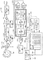
図1を参照すると、例示的な磁界センサ機構10は、磁界センサ12を含む。磁界センサ12は、電子回路18と接続された磁界検知素子16を有する磁界検知回路14を含む。電子回路18は、比較検出器18を含み得る。比較検出器18は、ある種の実施形態では、真のパワーオン状態(TPOS)検出器18aと、精密回転検出器18bであってもよく、双方とも以下にさらに充分に説明される。
Referring to FIG. 1, an exemplary magnetic
また、磁界センサ12は、磁石20をも含む。磁石20は、軸22に沿った方向の磁界を生成するように構成される。電子回路18は、出力信号24を生成するように構成される。この信号は、磁界センサ12の起動に近い時間期間には、TPOS検出器18aにより生成され、その後は精密回転検出器により生成可能である。
The
また、磁界センサ機構10は、特徴部26a、26b、26c、26dを有するカム26(たとえば、ギヤ)をも含み得る。カム26は、たとえば、方向32に回転するように構成されたシャフト30(すなわち、対象物)上に、配置され得る。
The magnetic
動作中は、カム26が回転すると、カムの特徴部26a、26b、26c、26dは、磁石20によって生成された磁界を遮断する。磁石20によって生成された磁界の遮断は、磁界検知素子16に検知され、出力信号24における状態遷移という結果になる。
In operation, as the
カムの特徴部26a、26b、26c、26dの固有の配列および間隔により、結果的に、TPOS検出器18aは、TPOSカム26がわずかな角度回転しただけで遷移するTPOS出力信号24を、提供可能となる。ある種の実施形態では、この信号は、エンジン制御コンピュータにより解釈されて、カム26およびカム26が配置されるシャフト30の絶対回転角が生成可能となる。
Due to the unique arrangement and spacing of the cam features 26a, 26b, 26c, 26d, the
さらに、以下に説明する回路および技術により、TPOS検出器18aは、磁界センサ12の起動時に、磁界センサ12が、ギヤ歯に近接しているか、またはギヤの谷に近接しているかどうかについての示度を提供可能となる。
Further, with the circuits and techniques described below, the
次に図2を参照すると、グラフ50は、たとえば、0度から360度という、対象物の回転角度単位の尺度での横軸を有する。また、グラフ50は、任意の単位による電圧単位の尺度での縦軸を含む。信号52は、たとえば、磁界検知素子16と関連した、図1の磁界センサ12内で生成された磁界信号と同一かまたは同様である。図1のカム26が回転するにつれて、カム26の特徴部26a、26b、26c、26dが図1の磁界検知素子16を通過するため、信号52の高状態期間は、これらの特徴部に対応することが、理解されるであろう。
Referring now to FIG. 2, a
磁界信号52は、連続したアナログ値を有するアナログ形式で示されているが、サンプリングされたアナログ値と同等の離散デジタル値を有する信号であってもよい。信号52は電圧信号として示されるが、他の実施形態では、信号52は、電流信号である。
The
所定の閾値54が図示され、図3と組み合わせて、以下にさらに説明される。所定の閾値54は、従来のTPOS検出器で用いられるものと同様である。複数の格納測定閾値のうちの1つに応じて(異なる時点で)算出された比較閾値56も図示され、図3と組み合わせて、以下にさらに説明される。複数の格納測定閾値のうちの1つに応じて算出された比較閾値56は、従来のTPOS検出器では用いられていない。
The
ここで用いられるように、「比較閾値」および「TPOS閾値」という用語は、実質的に同じ閾値を意味するものとして使用される。 As used herein, the terms “comparison threshold” and “TPOS threshold” are used to mean substantially the same threshold.
次に図3を参照すると、グラフ70は、たとえば、0度から360度という、対象物の回転角度単位の尺度での横軸を有する。また、グラフ70は、任意の単位による電圧単位の尺度での縦軸を含む。 Referring now to FIG. 3, a graph 70 has a horizontal axis, for example, on a scale of 0 to 360 degrees, in units of rotation of the object. Graph 70 also includes a vertical axis on a scale of voltage units in arbitrary units.
信号74には、2つの状態があり、両者間の遷移の位置は、図2の信号52が、所定の閾値54と上下に交差することにより、判別される。信号72には、2つの状態があり、両者間の遷移の位置は、図2の信号52が、算出閾値56と上下に交差することにより、判別される。したがって、図2の信号52と比較するために利用される閾値の位置すなわち値の変化は、結果として得られた両状態信号の遷移すなわちエッジの位置に影響することが、理解されるであろう。上述のように、自動車分野を含むがそれに限らない多くの用途に利用される場合、エッジの位置は、自動車が適切に動作するために非常に重要となり得る。
The signal 74 has two states, and the position of the transition between the two is determined by the
上述のように、磁界信号52は、たとえば、温度、および磁界センサと検知対象のカムまたはギヤとの空隙などの様々な環境ならびに電子的要因により、振幅が変化し得る。たとえば、温度、図1の磁界検知素子16とカム26との間の空隙、または他のパラメータにより、正のピークおよび負のピークの振幅が変化しても、磁界信号52の正のピークと負のピークとの間の好適な位置にある図2の算出閾値56と同等の閾値信号を維持することが望ましい。このような配列で、結果として得られた2つの状態信号72のエッジは、磁界信号52の正負のピークの振幅が変化し、また非対称に変化したとしても、同じ位置にとどまり得る。
As described above, the
図4を参照すると、磁界センサ400は、電流源404により駆動されるホール効果素子402を含む。ホール効果素子402は、磁界が、たとえば、磁界センサ400に近接するかまたはセンサ内に配置された磁石403により生成されると、その磁界に応答する。ギヤ450が回転すると、結果として、ホール効果素子により検知された磁界が変化し、また、ギヤ450が回転すると、磁界信号402aが交流信号になる結果をもたらし得る。
Referring to FIG. 4, the
ホール効果素子が図示されているが、任意の種類の磁界検知素子が利用可能である。また、単一の磁界検知素子が図示されているが、他の実施形態では、たとえば異なる配列で接続された2つ以上の磁界検知素子があってもよい。 Although a Hall effect element is shown, any type of magnetic field sensing element can be used. Also, while a single magnetic field sensing element is shown, in other embodiments there may be, for example, two or more magnetic field sensing elements connected in different arrangements.
磁界センサ400は、アンプ408と、プログラマブルフィルタであり得るフィルタ410と、加算回路412と、アンプ414とを備えた信号経路(アナログまたはデジタルまたは混合)を含む。ホール効果素子402は、磁界に応じて磁界信号402aを生成するように構成される。アンプ408(たとえば、ゲイン調整可能アナログ回路)は、磁界信号402aを受信するとともにゲイン制御信号416aを受信するように接続され、ゲイン調整された信号408aを生成するように構成されている。フィルタ410は、ゲイン調整された信号408aを受信するように接続されるとともに、フィルタ処理された信号410aを生成するように構成されている。加算回路412(たとえば、オフセット調整可能アナログ回路)は、フィルタ処理された信号410aを受信するとともにオフセット制御信号418aを受信するように接続され、オフセット調整された信号412aを生成するように構成されている。アンプ414は、オフセット調整された信号412aを受信するように接続され、ゲインおよびオフセット補正を有する出力信号414aを生成するように構成されている。
The
出力信号414aは、磁界センサ402に対して回転ギヤ450(または他の強磁性体または磁性体)があるときに振幅を有することが、理解されるであろう。また、出力信号414aには、オフセットが残っていることもある。
It will be appreciated that the output signal 414a has an amplitude when there is a rotating gear 450 (or other ferromagnetic or magnetic material) relative to the
また、アンプ408、414により実装される回路機能の順番は、ここに説明される一般的な機能を変更することがない任意の順番であってよいことも、理解されるであろう。また、回路機能が、アナログまたはデジタル領域のいずれかでなされることも、理解されるであろう。
It will also be appreciated that the order of the circuit functions implemented by the
他のある種の実施形態では、オフセット温度補償がなされず、この場合、温度センサ420およびADC422は不要であり、オフセット温度補正係数をEEPROM442内に格納する必要はない。
In certain other embodiments, no offset temperature compensation is provided, in which case the
他のある種の実施形態では、ゲイン温度補償がなされず、この場合、温度センサ420およびADC422は不要であり、ゲイン温度補正係数をEEPROM442内に格納する必要はない。
In certain other embodiments, there is no gain temperature compensation, in which case the
他のある種の実施形態では、ゲイン温度補償もオフセット温度補償も実行されず、この場合、少なくとも、セグメントプロセッサ424、係数テーブルEEPROM442、温度センサ、およびADC422は、必要ではない。これらの実施形態では、信号414aは、温度補償のない中間信号である。
In certain other embodiments, neither gain temperature compensation nor offset temperature compensation is performed, in which case at least the segment processor 424, coefficient table EEPROM 442, temperature sensor, and
また、磁界センサ400は回転モジュール417をも含む。このモジュールは、出力信号414aを受信するように接続されるとともに、少なくともギヤ450の回転を示し、必要に応じてギヤ450の回転速度を示し、必要に応じてギヤ450の回転方向を示す回転出力信号を生成するように、構成されている。回転モジュール417は、図8と組み合わせて以下に説明される。回転モジュールが、比較検出器(たとえば、TPOS検出器)と、精密回転検出器の少なくとも一部とを含むことが、充分であるといえる。
The
また、磁界センサ400は、温度センサ420を含み、この温度センサ420は、磁界センサ400の他の回路と同じ基板上に配置されることが好ましい。温度センサ420は、温度センサ420が遭遇する温度を表す温度信号420aを生成するように構成されている。アナログデジタル変換器(ADC)422は、温度信号420aを受信するように接続され、温度信号420aを表すデジタル温度信号422aを生成するように構成されている。
In addition, the
磁界センサ400は、デジタル温度信号422aを受信するように接続されたセグメントプロセッサ424を含み得る。セグメントプロセッサ424がいくつかの機能を実行するように構成されることが、以下の考察から明らかとなるであろう。セグメントプロセッサ424は、デジタル温度信号422a(すなわち、温度信号420a)が低下する温度セグメントを特定するように構成される。また、セグメントプロセッサ424は、特定された温度セグメントと関連付けられたゲイン補正係数442aの対および/またはオフセット補正係数442bの対を受信するように接続されてもよい。ゲイン補正係数442aの対および/またはオフセット補正係数442bの対は、特定された温度セグメントを規定する温度と関連付けられている。ゲイン補正係数442aの対および/またはオフセット補正係数442bの対は、制御信号426cを通じてセグメントプロセッサ424から要求され得る。
セグメントプロセッサ424は、デジタル温度信号422aに応じて、ゲイン補正係数442aの対を補間して、センサゲイン補正値430aを生成するように構成され得る。ゲイン制御信号416aは、センサゲイン補正値430aに関連するとともにこの値により決定されるアナログ信号であり得る。
Segment processor 424 may be configured to generate a sensor
また、セグメントプロセッサ424は、デジタル温度信号422aに応じて、オフセット補正係数442bの対を補間して、センサオフセット補正値432aを生成するように構成され得る。オフセット制御信号418aは、センサオフセット補正値432aに関連するとともにこの値により決定されるアナログ信号であり得る。
Also, the segment processor 424 can be configured to generate a sensor offset
セグメントプロセッサ424は、デジタル信号または値を処理するデジタル回路であってもよいことが、理解されるであろう。セグメントプロセッサ424は、上述のアナログ回路のゲインおよび/またはオフセットを制御する。 It will be appreciated that segment processor 424 may be a digital circuit that processes digital signals or values. The segment processor 424 controls the gain and / or offset of the analog circuit described above.
また、磁界センサ400は、複数のゲイン補正係数および/または複数のオフセット補正係数を保持するように構成されたEEPROM442を含み得る。これらの係数は、複数の温度セグメントの温度境界と関連付けられている。ある種の実施形態では、選択された5つの温度境界があり、各境界は、それぞれゲイン補正係数(TDSense)およびオフセット補正係数(DQVO)と関連付けられている。
Also, the
複数のゲイン補正係数および複数のオフセット補正係数は、磁界センサ400の製造時に、または、その後の任意の時点で、シリアル通信リンクであり得る通信リンク438上で、信号438aを介して、EEPROM442内に格納され得る。複数のゲイン補正係数および複数のオフセット補正係数を定める方法について、図7と組み合わせて以下に説明する。
The plurality of gain correction factors and the plurality of offset correction factors are stored in EEPROM 442 via
また、磁界センサ400は、ユーザゲイン補正値444aをセグメントプロセッサ424に提供するように接続された、ユーザゲイン補正EEPROM444を含み得る。また、磁界センサ400は、ユーザオフセット補正値446aをセグメントプロセッサ424に提供するように接続された、ユーザオフセットEEPROM446を含み得る。ユーザゲインEEPROM444は、ユーザゲイン補正値444aを、信号438cを介して、通信リンク438上で受信可能である。ユーザオフセットEEPROM446は、ユーザオフセット補正値446aを、信号438dを介して、通信リンク438上で受信可能である。
また、磁界センサ400は、補間制御信号440aをセグメントプロセッサ424へ提供するように接続された、プログラム制御EEPROM440を含み得る。補間制御については、以下にさらに充分に説明する。プログラム制御EEPROM440は、補間制御信号440aを、信号438bを介して、通信リンク438上で受信し得る。
セグメントプロセッサ424は、デジタル温度信号422aを受信するように接続されるとともにゲイン補正係数442aの対および/またはオフセット補正係数442bの対を受信するように接続された、補間プロセッサ426を備え得る。また、ある種の実施形態では、補間プロセッサ426は、制御信号440aを受信するように接続され得る。制御信号440aは、ゲインの種類および/または補間プロセッサ426により実行されるオフセット補間を、決定することができる。補間の種類については、以下にさらに説明する。
Segment processor 424 may include an interpolation processor 426 connected to receive
補間プロセッサ426は、補間されたゲイン補正値426aおよび/または補間されたオフセット補正値426bを生成するように構成されている。その目的のために、補間プロセッサ426は、デジタル温度信号422a(すなわち、温度信号420a)が低下する上述の温度セグメントを特定するように構成される。また、補間プロセッサ426は、特定された温度セグメントを規定する2つの温度と関連付けられた、上述のゲイン補正係数442aの対および/または上述のオフセット補正係数442bの対を受信するように、接続される。
Interpolation processor 426 is configured to generate interpolated gain correction value 426a and / or interpolated offset
補間プロセッサ426は、デジタル温度信号422aを用いて、測定された温度が、複数の温度セグメントのうちのどの中にあるかを特定することができる。したがって、適切なゲイン補正係数442aの対および/またはオフセット補正係数442bの対は、制御信号426cにより、補間プロセッサ426から要求され得る。
The interpolation processor 426 can use the
磁界センサ400は、補間されたゲイン補正値426aおよび/または補間されたオフセット補正値426bを受信するように接続されるとともに、ユーザゲイン補正値444aおよび/またはユーザオフセット補正値446aを受信するように接続された、結合プロセッサ428を備え得る。結合プロセッサ428は、補間されたゲイン補正値426aを、ユーザゲイン補正値444aと結合し、および/または補間されたオフセット補正値426bを、ユーザオフセット補正値446aと結合するように構成されている。したがって、結合プロセッサ428は、結合ゲイン補正値428aおよび/または結合オフセット補正値428bを生成するように構成され、これらの値は、ゲイン調整レジスタ430およびオフセット調整レジスタ432に、それぞれ格納され得る。
デジタルアナログ変換器(DAC)434は、格納されたゲイン補正値430aを受信するように接続されるとともに、ゲイン制御信号416aを生成するように構成されたゲイン調整回路416により受信されるゲイン補正信号434aを生成するように構成され得る。DAC436は、格納されたオフセット補正値432aを受信するように接続されるとともに、オフセット制御信号418aを生成するように構成されたオフセット調整回路418により受信されるオフセット補正信号436aを生成するように構成され得る。
A digital-to-analog converter (DAC) 434 is connected to receive the stored
ここにはDACS434、436が示されているが、上述の実施形態のうち、様々な回路機能がデジタル領域でなされるものにおいては、DACS434、436はなくともよい。
Although the
特定の一実施形態では、補間されたゲイン補正値426aを得るために、補間プロセッサ426により実行されるゲイン補間は、以下の形式の線形補間である。 In one particular embodiment, the gain interpolation performed by the interpolation processor 426 to obtain an interpolated gain correction value 426a is a linear interpolation of the form:

ここで、CoeffAおよびCoeffBは、特定された温度セグメントを規定するゲイン補正係数442aの対であり、temp[4:0]は、デジタル温度信号422aの下位5ビットを表し、これらは、7ビット値となり得る。
Where CoeffA and CoeffB are a pair of gain correction coefficients 442a that define the specified temperature segment, and temp [4: 0] represent the lower 5 bits of
ある種の実施形態では、補間プロセッサ426は、複数のゲイン(感度)の処理の選択肢を保持し、処理の選択肢(補間の種類、すなわち上述の等式)は、制御信号440aに応じて選択される。 In certain embodiments, the interpolation processor 426 holds multiple gain (sensitivity) processing options, and the processing options (interpolation type, ie, the above equation) are selected in response to the control signal 440a. You.
いくつかの種類の補間、たとえば、高次補間が、3つ以上の補正係数を利用することになるので、ある種の実施形態は、各温度セグメントと関連付けられた3つ以上のゲインおよび/またはオフセット補正係数を格納して用いる。 Because some types of interpolation, eg, higher order interpolation, will utilize more than two correction factors, certain embodiments may include more than two gains and / or gains associated with each temperature segment. The offset correction coefficient is stored and used.
ある種の実施形態では、結合プロセッサ428は、以下の等式に従って、補間されたゲイン補正値426aをユーザゲイン補正値444aと組み合わせ、結果的に結合ゲイン補正値428aを得る。
In certain embodiments, combination processor 428 combines interpolated gain correction value 426a with user
ここで、SENSFINEは、ユーザゲイン補正値444aであり、KDEVは、特定の種類の磁界センサの感度を表すデバイス固有の定数である(たとえば、十進法で74または十進法で206)。
Here, SENS FINE is the user
特定の一実施形態では、補間されたオフセット補正値426bを得るために、補間プロセッサ426により実行されるオフセット補間は、以下の形式の線形補間である。
In one particular embodiment, the offset interpolation performed by interpolation processor 426 to obtain interpolated offset
ここで、CoeffAおよびCoeffBは、特定された温度セグメントを規定するオフセット補正係数442bの対であり、temp[4:0]は、デジタル温度信号442aの下位5ビットを表し、これらは、7ビット値になり得る。
Where CoeffA and CoeffB are a pair of offset
上述のように、ある種の実施形態では、補間プロセッサ426は、複数のオフセットの処理の選択肢を保持し、処理の選択肢(補間の種類、すなわち上述の等式)は、制御信号440aに応じて選択される。ある種の実施形態では、この選択は、以下の線形補間の複数の種類からなされる。各種類は、2倍ずつ異なる(1ビットシフト)。 As described above, in certain embodiments, the interpolation processor 426 maintains a plurality of offset processing options, and the processing options (interpolation type, ie, the above equation) are dependent on the control signal 440a. Selected. In certain embodiments, this selection is made from several types of linear interpolation: Each type is twice different (one bit shift).
ある種の実施形態では、結合プロセッサ428は、以下の等式に従って、補間されたオフセット補正値426bをユーザオフセット補正値446aと組み合わせ、結果的に結合オフセット補正値428bを得る。
In certain embodiments, combination processor 428 combines interpolated offset
ここで、QVOは、ユーザオフセット補正値446aである。
Here, QVO is the user offset
予期されるとおり、上述のゲインおよびオフセットの等式から、ユーザゲイン補正値444aは積に適用され、ユーザオフセット補正値446aは和に適用されることが、理解されるであろう。
As would be expected, from the gain and offset equations described above, it will be appreciated that the
次に、図5を参照すると、グラフ500は、百分率で変化する感度単位の尺度での縦軸508を有する。第1の横軸510は、磁界センサ(すなわち、図4の温度センサ420による)が遭遇する摂氏温度単位の尺度である。第2の横軸512は、温度を表す7ビットのデジタル符号に対応した単位の尺度であるが、0から127までの十進数単位になっている。軸512は、図4のデジタル温度信号422aに対応する。
Referring now to FIG. 5, a
特性曲線502は、ゲイン補正値が適用されていない磁界センサの相対感度(室温506での感度が基準)を表す。特性曲線502により表された相対感度は、低温では低くなる傾向があり、高温では高くなる傾向があることがわかる。
A
第1の温度である−40℃で、ゲイン補正係数504a(TDSense0(図4))は、特性曲線502の相対感度の低下とは反対になっている。ゲイン補正係数504aは、磁界センサが温度−40度に遭遇するときに、磁界センサに適用可能であり、室温506における感度から実質的に感度変化しない結果となることが、理解されるであろう。同様に、他のゲイン補正係数504b、504c、504d、504e(それぞれTDSense1、TDSense2、TDSense3、TDSense4(図4))は、個々の温度にて、室温506における感度から実質的に感度変化しないようにするために、関連付けられた他の温度(それぞれ11.25、62.5、113.75、165.00℃)に適用可能である。
At the first temperature of −40 ° C., the
5つの温度セグメントが図示されている。すなわち、−40.00〜11.25、11.25〜62.5、62,5〜113.75、および113.75〜165.00℃である。 Five temperature segments are shown. That is, -40.00 to 11.25, 11.25 to 62.5, 62,5 to 113.75, and 113.75 to 165.00 ° C.
図4のデジタル温度信号422aにより表される、磁界センサが遭遇する実際の測定温度に応じて特定された、任意の温度セグメント内、たとえば、温度セグメント11.25〜62.5内で、補間プロセッサ426(図4)は、特定された複数の温度セグメントの境界と関連付けられた、複数のゲイン補正係数(たとえば、504b、504c)を補間して、補間されたゲイン補正値(たとえば、図4の426a)を定め、特定の測定温度にて使用可能である。補間されたゲイン補正値は、磁界センサ400に適用されて、磁界センサの感度を、室温506での感度から実質的に不変に保つことができる。
Within any temperature segment, e.g., within temperature segments 11.25 to 62.5, identified according to the actual measured temperature encountered by the magnetic field sensor, represented by
既に図示および説明したように、感度補間は、線形補間であってもよい。ただし、他の実施形態では、ゲイン補間は、他の形式であってもよい。たとえば、二次補間、または非線形補間などの他の形式であってもよい。 As already shown and described, the sensitivity interpolation may be a linear interpolation. However, in other embodiments, the gain interpolation may be in other forms. For example, other forms such as quadratic interpolation or non-linear interpolation may be used.
5つのゲイン補正係数504a〜504e、および関連付けられた4つの温度セグメントが図示されているが、他の実施形態では、5つより多いかまたは5つより少ないゲイン補正係数、および4つより多いかまたは4つより少ない関連付けられた温度セグメントがあってもよい。ゲイン補正係数の個数、および関連付けられた温度セグメントの数は、所望の精度、およびゲイン補正係数を格納するEEPROM442(図4)の所望の最大物理容量に応じて、選択され得る。一般に、EEPROM442内に格納されるゲイン補正係数の個数が増えるほど、補間されたゲイン補正係数の精度が高くなり、磁界センサの補正された相対感度の精度が高くなる。
Although five
温度セグメントは、温度数と同数として図示されているが、他の実施形態では、温度セグメントは、温度数と異なっていてもよい。たとえば、ある種の実施形態では、室温506に近い温度セグメントは、室温106から離れた温度セグメントよりも広い(または狭い)温度範囲であってもよい。
Although the temperature segments are shown as having the same number of temperatures, in other embodiments, the temperature segments may be different from the number of temperatures. For example, in certain embodiments, a temperature segment near
特定の種類の個々の磁界センサは、図7と組み合わせてより完全に説明する処理により生成された、様々なゲイン補正係数504a〜504eを有していてもよい。ただし、ある種の実施形態では、特定の種類の磁界センサの各々は、同一のゲイン補正係数504a〜504eを有していてもよい。
Individual magnetic field sensors of a particular type may have various
図7と組み合わせて以下にさらに説明するように、ゲイン補正係数504a〜504eのいくつか(または全て)は、磁界センサ(またはそれ以降)に、特定のゲイン補正係数504a〜504eが格納された特定の1つの磁界センサの複数の温度での相対感度の直接測定値を乗じる間に、選択(すなわち、測定)可能である。ただし、ある種の実施形態では、ゲイン補正係数504a〜504eのうちの全てには満たない個数の係数は、直接測定の結果もたらされ、ゲイン補正係数504a〜504eのうちの他のものは、感度特性曲線502の形状から抽出される。換言すると、たとえば、ゲイン補正係数504aは、−40.00度および室温506での相対感度測定により生成され得るものであり、他のゲイン補正係数504b〜504eは、感度特性曲線502の形状についての知見から推定可能である。
As described further below in conjunction with FIG. 7, some (or all) of the
図示の特性曲線502は、複数の同じ種類の磁界センサから得られた平均感度特性を表すものであってもよい。他の種類の磁界センサは、他の形状の特性曲線を有し得る。
The illustrated
特定の磁界センサ用のゲイン補正係数504a〜504eのいくつか(または全て)を抽出するために特性曲線502を用いる際、特性曲線502は、同じ種類の全ての磁界センサに共通の同じ形状を保ち得るが、同種の個々の磁界センサのために、大きさを拡大または縮小させ得ることが、理解されるであろう。たとえば、個々の磁界センサの相対感度が、室温および−40度でも測定された場合、ならびに−40度での相対感度が特性曲線502で表される相対感度よりも低い場合、測定されている磁界センサの特性曲線は、−40度ではより下方へ曲がり、165度ではより上方へ曲がるが、その他では同じ形状を保つと想定され得る。このように、室温での感度測定、および任意の他の温度での相対感度測定(室温での感度を基準とする)だけで、特性曲線502と同様の(同一形状の)特性曲線(ただし、尺度は異なる)が抽出可能であり、他のゲイン補正係数が推定可能である。
When using the
感度特性曲線502の特定の形状は、特定の種類の磁界センサ次第であることが、理解されるであろう。さらに、特性曲線502は、特定の種類の磁界センサに特有の曲線からわずかに(尺度において)異なることもある。したがって、特定の種類の磁界センサのうちの様々な複数のセンサを特徴づけ、特性曲線502の形状を特定するために平均をとることは、有益となり得る。後に、この曲線は、同じ種類の個々の磁界センサに適合させて尺度が拡大または縮小され得る。
It will be appreciated that the particular shape of the sensitivity
次に、図6を参照すると、グラフ600は、9ビットのデジタル値で表される線形単位における、直流オフセット電圧変化の単位の尺度での縦軸608を有する。第1の横軸610は、磁界センサ(すなわち、図4の温度センサ420による)が遭遇する摂氏温度単位の尺度である。第2の横軸612は、温度を表す7ビットのデジタル符号に対応した単位の尺度であるが、0から127までの十進数単位になっている。軸612は、図4のデジタル温度信号422aに対応する。
Referring now to FIG. 6, a
特性曲線602は、オフセット補正値が適用されていない磁界センサの相対オフセット(室温606でのオフセットが基準)を表す。特性曲線602により表されるオフセットは、低温では、室温でのオフセット(通例、0.0V)を基準として一方の方向にある傾向があり、高温では、室温でのオフセットを基準として他方の方向にある傾向があることがわかる。
A
第1の温度である−40℃で、オフセット補正係数604a(DQVO_0(図4))は、特性曲線602の相対オフセットの低下とは反対になっている。オフセット補正係数604aは、磁界センサが温度−40度に遭遇するときに、磁界センサに適用可能であり、室温606におけるオフセット(0.0V)から実質的にオフセット変化しない結果となることが、理解されるであろう。同様に、他のオフセット補正係数604b、604c、604d、604e(それぞれDQVO_1、DQVO_2、DQVO_3、DQVO_4(図4))は、特定の温度にて、室温606におけるオフセットからオフセット変化しないようにするために、関連付けられた他の温度(それぞれ11.25、62.5、113.75、165.00℃)で適用可能である。
At a first temperature of −40 ° C., the offset
図5に示すように、5つの温度セグメントが図示されている。すなわち、−40.00〜11.25、11.25〜62.5、62.5〜113.75、および113.75〜165.00℃である。 As shown in FIG. 5, five temperature segments are illustrated. That is, -40.00 to 11.25, 11.25 to 62.5, 62.5 to 113.75, and 113.75 to 165.00 ° C.
図4のデジタル温度信号422aにより表される、磁界センサが遭遇する実際の測定温度に応じて特定された、任意の温度セグメント内、たとえば、温度セグメント11.25〜62.5内で、補間プロセッサ426(図4)は、温度セグメントの境界と関連付けられた、複数のオフセット補正係数(たとえば、604b、604c)を補間して、補間されたオフセット補正値(たとえば、図4の426b)を定め、特定の測定温度にて使用可能である。補間されたオフセット補正値は、磁界センサに適用されて、磁界センサのオフセットを、室温606でのオフセットから実質的に不変に保つことができる。
Within any temperature segment, e.g., within temperature segments 11.25 to 62.5, identified according to the actual measured temperature encountered by the magnetic field sensor, represented by
既に図示および説明したように、オフセット補間は、線形補間であってもよい。ただし、他の実施形態では、オフセット補間は、他の形式であってもよい。たとえば、二次補間、または非線形補間などの他の形式であってもよい。 As already shown and described, the offset interpolation may be a linear interpolation. However, in other embodiments, the offset interpolation may be in other forms. For example, other forms such as quadratic interpolation or non-linear interpolation may be used.
5つのオフセット補正係数604a〜604e、および関連付けられた4つの温度セグメントが図示されているが、他の実施形態では、5つより多いかまたは5つより少ないオフセット補正係数、および4つより多いかまたは4つより少ない関連付けられた温度セグメントがあってもよい。オフセット補正係数の個数、および関連付けられた温度セグメントの数は、所望のオフセット精度、およびオフセット補正係数を格納するEEPROM442(図4)の所望の最大物理容量に応じて、選択され得る。一般に、EEPROM442内に格納されるオフセット補正係数の個数が増えるほど、補間されたオフセット補正係数の精度が高くなり、磁界センサの補正された相対オフセットの精度が高くなる。
Although five offset
温度セグメントは、温度数と同数として図示されているが、他の実施形態では、温度セグメントは、温度数と異なっていてもよい。たとえば、ある種の実施形態では、室温606に近い温度セグメントは、室温606から離れた温度よりも広い(または狭い)温度範囲であってもよい。
Although the temperature segments are shown as having the same number of temperatures, in other embodiments, the temperature segments may be different from the number of temperatures. For example, in certain embodiments, a temperature segment near
特定の種類の個々の磁界センサは、図7と組み合わせてより完全に以下に説明する処理により生成された、異なるオフセット補正係数604a〜604eを有していてもよい。ただし、ある種の実施形態では、特定の種類の磁界センサの各々は、同一のオフセット補正係数604a〜604eを有していてもよい。
Certain types of individual magnetic field sensors may have different offset
図7と組み合わせてさらに以下に説明するように、オフセット補正係数604a〜604eのいくつか(または全て)は、磁界センサ(またはそれ以降)に、特定のオフセット補正係数604a〜604eが格納された特定の磁界センサの複数の温度での相対オフセットの直接測定値を乗じる間に、選択(すなわち、測定)可能である。ただし、ある種の実施形態では、オフセット補正係数604a〜604eのうちの全てには満たない個数の係数は、直接測定の結果もたらされ、オフセット補正係数604a〜604eのうちの他のものは、オフセット特性曲線602から抽出される。換言すると、たとえば、オフセット補正係数604aは、−40.00度および室温606での相対オフセット測定により生成され得るものであり、他のオフセット補正係数604b〜604eは、オフセット特性曲線602の形状についての知見から推定可能である。
As described further below in conjunction with FIG. 7, some (or all) of the offset
図示の特性曲線602は、複数の同じ種類の磁界センサから得られた平均オフセット特性を表すものであってもよい。他の種類の磁界センサは、他の形状のオフセット特性曲線を有し得る。
The illustrated
特定の磁界センサ用のオフセット補正係数604a〜604eのいくつか(または全て)を抽出するためにオフセット特性曲線602を用いる際、オフセット特性曲線602は、同じ種類の全ての磁界センサに共通の同じ形状を保ち得るが、同種の個々の磁界センサのために、大きさを拡大または縮小させ得ることが、理解されるであろう。たとえば、個々の磁界センサの相対オフセットが、室温および−40度でも測定される場合、ならびに−40度での相対オフセットが特性曲線602で表される相対感度よりも低い場合、測定されている磁界センサの特性曲線は、−40度ではより下方へ曲がり、165度ではより上方へ曲がるが、その他では同じ形状を保つと想定され得る。このように、室温でのオフセット測定、および任意の他の温度での相対オフセット測定(室温でのオフセットを基準とする)だけで、特性曲線602と同様の(同一形状の)特性曲線(ただし、尺度は異なる)が抽出可能であり、他のオフセット補正係数が推定可能である。
When using the offset
オフセット特性曲線602の特定の形状は、特定の種類の磁界センサ次第であることが、理解されるであろう。さらに、特性曲線602は、特定の種類の磁界センサに特有の曲線からわずかに(たとえば、異なる尺度において)異なることもある。したがって、特定の種類の磁界センサのうちの様々な複数のセンサを特徴づけ、オフセット特性曲線602の形状を特定するために平均をとることは、有益となり得る。後に、この曲線は、同じ種類の個々の磁界センサに適合させて尺度が拡大または縮小され得る。
It will be appreciated that the particular shape of the offset
図5および図6の上述の例から、一実施形態では、5つの温度と関連付けられた5つのゲイン補正係数、および同じ5つの温度と関連付けられた5つのオフセット補正係数があることが、理解されるであろう。ただし、ゲイン補正係数およびオフセット補正係数は、同じ温度と関連付けられる必要はない。図4のEEPROM442は、例示的な5つのゲイン補正係数(TDSense0〜TDSense4)および例示的な5つのオフセット補正係数(DQVO_0〜DQVO_4)を格納するものとして図示されている。 From the above examples of FIGS. 5 and 6, it is understood that in one embodiment there are five gain correction factors associated with five temperatures and five offset correction factors associated with the same five temperatures. Will be. However, the gain correction coefficient and the offset correction coefficient need not be associated with the same temperature. The EEPROM 442 of FIG. 4 is illustrated as storing five exemplary gain correction factors (TDSense0-TDSense4) and five exemplary offset correction factors (DQVO_0-DQVO_4).
以下の図7および図10は、磁界センサ400(図4)として実装されることになる、以下に考察される技術に対応した、フローチャートを示すことが、理解されるであろう。矩形要素(図7の要素704に代表される)は、ここでは「処理ブロック」と称し、コンピュータソフトウェア命令または命令群を表す。ダイアモンド形要素(図10の要素1004に代表される)は、ここでは、「判断ブロック」と称し、コンピュータソフトウェア命令または命令群を表し、これらは、処理ブロックで表されるコンピュータソフトウェア命令の実行に影響する。
It will be appreciated that FIGS. 7 and 10 below show flowcharts corresponding to the techniques discussed below that will be implemented as magnetic field sensors 400 (FIG. 4). Rectangular elements (represented by
それ以外にも、処理ブロックおよび判断ブロックは、デジタル信号処理回路または特定用途向け集積回路(ASIC)などの機能的に等価な回路により実行されるステップを表す。フローチャートは、特定のプログラミング言語の構文を示しているわけではない。むしろ、フローチャートは、当業者が回路を作製するかまたはコンピュータソフトウェアを生成して、特定の装置における必要な処理を実行するために必要な機能情報を、示すものである。ループおよび変数の初期化、一時的変数の使用など、多くのルーチンプログラム要素は示されていないことが、理解されるであろう。ここに特記しない限り、説明された複数のブロックの特定のシーケンスは、説明のためのものに過ぎず、本発明の趣旨から逸脱することなく変更可能であることが、当業者には理解されるであろう。このように、特記しない限り、以下に説明するブロックは、順序付けられていない。これは、可能であれば、ステップは、便利であるかまたは所望の任意の順序で実行可能であることを意味する。 Additionally, processing and decision blocks represent steps performed by functionally equivalent circuits such as digital signal processing circuits or application specific integrated circuits (ASICs). The flowcharts do not illustrate the syntax of any particular programming language. Rather, flowcharts represent the functional information required by those skilled in the art to create circuits or generate computer software to perform the required processing on the particular device. It will be appreciated that many routine program elements are not shown, such as initialization of loops and variables, use of temporary variables, and the like. It will be understood by those skilled in the art that, unless otherwise noted, the particular sequence of blocks described is for illustration only and may be changed without departing from the spirit of the invention. Will. Thus, unless otherwise noted, the blocks described below are not ordered. This means that, where possible, the steps can be performed in any convenient or desired order.
次に、図7を参照すると、例示的な方法700は、工場にて、図1の磁界センサ10が製造されると、ブロックの組702から開始する。ブロック704では、較正温度および関連付けられた温度セグメントの組が、選択される。図4〜図6と組み合わせて上述した例では、選択温度が、たとえば、−40.00、11.25、62.5、113.75、および165.00℃の5つあり、選択温度の隣接する対により規定された、関連温度セグメントが4つあり得る。ただし、上述のように、選択温度は、5つより多くまたは5つより少なくともよく、関連温度セグメントは、4つより多くまたは4つより少なくともよく、選択温度は、均等に配列されている必要はない。
Referring now to FIG. 7, an
ブロック706では、相対ゲインおよび相対オフセット(室温でのゲインおよびオフセットが基準)が、全ての選択温度で、または、たとえば−40.00℃のみなど、選択された温度のサブセットで、測定され得る。
At
ブロック708では、相対感度の測定値に基づき、ゲインおよびオフセット補正係数が、測定がなされた温度について定められる。ゲインおよびオフセット補正係数は、測定相対感度および相対オフセットのずれとは反対側となり得る。 At block 708, based on the relative sensitivity measurements, gain and offset correction factors are determined for the temperature at which the measurements were made. The gain and offset correction factors can be on the opposite side of the deviation of the measured relative sensitivity and relative offset.
ブロック710では、問題となる特定の磁界センサについて相対感度およびオフセットの直接測定がなされない選択温度のために、他のゲインおよびオフセット補正係数が定められ得る。上述のように、他のゲインおよびオフセット補正係数は、同じ種類の複数の磁界センサの測定値の平均から抽出された曲線の形状についての知見を用いて、感度特性曲線および/またはオフセット特性曲線の生成に従って定められ得る。同じ形状を用いることで、感度(ゲイン)特性曲線およびオフセット特性曲線は、測定値の平均と同じ形状を有し得るが、ブロック706で得られた感度およびオフセットの測定値に従って、大きさが拡大または縮小され得る。
At
ブロック712では、ゲインおよびオフセット補正係数(たとえば、5つのゲイン補正係数および5つのオフセット補正係数)が、磁界センサ内に格納される。たとえば、図4のEEPROM442内に、たとえば、図4の通信リンク438などのシリアル通信リンクを介して、保存される。 At block 712, the gain and offset correction factors (eg, five gain correction factors and five offset correction factors) are stored in the magnetic field sensor. For example, stored in EEPROM 442 of FIG. 4, for example, via a serial communication link such as communication link 438 of FIG.
ブロック714では、ある種の実施形態において、ゲイン補間式および/またはオフセット補間の種類(式)が、複数の補間の種類から選択され得る。上記の式1、3、4および5を参照されたい。
At block 714, in certain embodiments, the type of gain interpolation and / or offset interpolation may be selected from a plurality of interpolation types.
ブロック716では、補間の種類の選択は、たとえば、図4のEEPROM440内に、たとえば、図4の通信リンク438などのシリアル通信リンクを介して、値として保存される。
At block 716, the selection of the type of interpolation is stored as a value, for example, in the
処理の残りのブロック700は、通常の動作の領域において、連続してまたは時々に、磁界センサにより実行可能である。
The remaining
ブロック718では、磁界センサは、その温度を、たとえば、図4の温度センサ420によって測定する。
At block 718, the magnetic field sensor measures its temperature, for example, by the
ブロック720では、磁界センサは、ブロック704にて選択された温度セグメントのどこに測定された温度があるか、特定する。
In block 720, the magnetic field sensor determines where the measured temperature is in the temperature segment selected in
ブロック722では、磁界センサ、たとえば、図4の補間プロセッサ426は、測定された温度に従って、特定された温度セグメントを規定する、ブロック712にて格納されたゲイン補正係数間で、補間する。このように、補間されたゲイン補正値(たとえば、図4の426a)が定められる。補間は、上記の式1に従ってなされる。
At
ブロック724以前では、磁界センサは、ユーザゲイン補正値を受信し得る。この値は、たとえば、ユーザゲイン補正値の図4のEEPROM444内に図4の通信リンク438を介して格納された値444aである。ある種の実施形態では、ユーザゲイン補正値は、係数0.75と1.25との間で、ユーザの好みに応じて、磁界センサの感度を調整するためにのみ用いられる。
Prior to block 724, the magnetic field sensor may receive a user gain correction value. This value is, for example, the
ブロック726では、補間されたゲイン補正値は、ユーザゲイン補正値(たとえば、図4の結合プロセッサ428による)と組み合わされて、結合ゲイン補正値(たとえば、図4の428a)を定める。
At
ブロック728では、たとえば、図4のゲイン調整レジスタ430内に、結合ゲイン補正値が格納される。 At block 728, the combined gain correction value is stored, for example, in the gain adjustment register 430 of FIG.
ブロック730では、保存されたゲイン補正値が、磁界センサに適用されて、図4のDAC434およびゲイン調整回路416を介して、その感度(すなわち、ゲイン)を調整する。
At block 730, the stored gain correction value is applied to the magnetic field sensor to adjust its sensitivity (ie, gain) via the
ブロック732では、磁界センサ、たとえば、図4の補間プロセッサ426は、測定された温度に応じて、特定された温度セグメントを規定するブロック712にて格納されたオフセット補正係数間で、補間する。このように、補間されたオフセット補正値(たとえば、図4の426b)が定められる。補間は、上記の式3に従ってなされる。
At
ブロック734以前では、磁界センサは、ユーザオフセット補正値を受信し得る。この値は、たとえば、ユーザオフセット補正値の図4のEEPROM446内に図4の通信リンク438を介して格納された値446aである。
Prior to block 734, the magnetic field sensor may receive a user offset correction value. This value is, for example, the
ブロック736では、補間されたオフセット補正値は、ユーザオフセット補正値と(たとえば、図4の結合プロセッサ426により)組み合わされて、結合オフセット補正値(たとえば、図4の428b)を定める。 At block 736, the interpolated offset correction value is combined with the user offset correction value (eg, by the combining processor 426 of FIG. 4) to determine a combined offset correction value (eg, 428b of FIG. 4).
ブロック738では、たとえば、図4のオフセット調整レジスタ432内に、結合オフセット補正値が格納される。 At block 738, the combined offset correction value is stored, for example, in the offset adjustment register 432 of FIG.
ブロック740では、保存されたオフセット補正値が、磁界センサに適用されて、図4のDAC436およびオフセット調整回路418を介して、そのオフセットを調整する。
At block 740, the stored offset correction value is applied to the magnetic field sensor to adjust its offset via the
上述の技術により、磁界センサは、室温での磁界センサの感度およびオフセットと比べて、磁界センサの温度に対して不変または変化が非常にわずかな感度およびオフセットを維持することができる。 With the techniques described above, the magnetic field sensor can maintain a sensitivity and offset that is invariant or changes very little with temperature of the magnetic field sensor as compared to the sensitivity and offset of the magnetic field sensor at room temperature.
上述の回路および技術により、感度およびオフセットが、温度に対して安定しているので、以下に説明する閾値も温度に対して安定することがわかる。なお、この閾値は、図4の回転モジュール417により、図4の信号414aから抽出される。ただし、図4の磁界センサ402とギヤ450との間の空隙は、実装例毎に異なり得るか、または、たとえば、機械的摩耗などにより経時的に変化し得ることも、理解されるであろう。したがって、信号414aの大きさは、空隙の寸法に応じてやはり変化することがあり、以下に説明する閾値は、空隙の変化または違いによって変化するかまたは異なり得る。なお、この閾値は、信号414aから抽出される。
It can be seen that the thresholds described below are also stable with temperature because the sensitivity and offset are stable with temperature by the circuits and techniques described above. The threshold is extracted from the signal 414a in FIG. 4 by the
次に、図8を参照すると、回転モジュール800は、図4の回転モジュール417と同一または同様であり得る。回転モジュール800は、信号818を受信するように接続されている。この信号は、図4の信号414aと同一であるかまたは同様であり得る。上述のように、信号414の大きさおよび信号818の大きさは、温度に対して安定しているが、たとえば、空隙などの機械的考慮要素に応じて変化し得る。
Referring now to FIG. 8, the rotation module 800 can be the same or similar to the
回転モジュール800は、たとえば、比較検出器802および精密回転検出器810など、異なる2種の回転検出器を含み得る。
The rotation module 800 may include two different types of rotation detectors, such as, for example, a
比較検出器802は、ある種の実施形態では、真のパワーオン状態(TPOS)検出器として動作し得ることが、理解されるであろう。特に、通例、図4と組み合わせて上述したように、単一の磁界センサが用いられるところでは、比較検出器802は、歯の検出器(エッジ検出器に対向)として動作可能であるので、TPOS機能を提供し、ギヤ450が回転していないときであっても、ギヤ450(図4)内での歯を谷から識別することができる。
It will be appreciated that the
ただし、他の実施形態では、図4の磁界センサ400と同様の磁界センサは、異なる配列で接続された2つ以上の磁界検知素子を使用可能である。これらの実施形態は、エッジ検出器(歯の検出器に対向)を提供しており、ギヤ450が回転していないときには、歯を谷から識別することができないのでTPOS機能は提供していない。これらの実施形態について、比較検出器802は、TPOS検出器ではないが、ここに図示および説明する形態をとっている。
However, in other embodiments, a magnetic field sensor similar to the
上記内容を考慮すると、比較検出器802は、磁界検知素子(たとえば、図4の402)の配置に応じて、歯の検出器(たとえば、TPOS検出器)またはエッジ検出器として動作可能であることが、理解されるであろう。したがって、ここで用いられるように、「比較検出器」という用語は、比較閾値を受信するように動作可能な比較器を含んで信号を比較閾値と比較する回路検出器を、説明するために用いられる。
In view of the above, the
比較検出器802は、実質的に、起動が迅速であり、起動時に、正確な比較検出器出力信号806aを提供する。一方、精密回転検出器810は、起動して正確な精密回転検出器出力信号810aを提供するのに、より長い時間がかかる。
The
様々な種類の精密回転検出器が知られている。いくつかの精密回転検出器は、信号818の正のピークの振幅を表す正のピーク信号810b、および信号818の負のピークを表す負のピーク信号810cを、内部的に提供する。ピーク間では、正のピーク信号810bおよび負のピーク信号810cは、ピークの振幅を表す値を保持し得る。このように、多くの従来の配列では、正のピーク信号810bおよび負のピーク信号810cは、入力信号818のそれぞれのピークを取得して保持するステップ型の特徴を有する。
Various types of precision rotation detectors are known. Some precision rotation detectors internally provide a positive peak signal 810b, representing the amplitude of the positive peak of
比較検出器802は、比較器806を含み得る。この比較器は、アナログ比較器か、またはデジタル比較器であり得る。比較器806は、閾値モジュール816により生成された比較閾値816a(たとえば、TPOS閾値)を受信するように接続されている。このモジュールについては、図9と組み合わせてより完全に後述する。
出力スイッチ812は、比較検出器出力信号806aおよび精密回転検出器出力信号810aを受信するように、接続され得る。スイッチ変更ロジックモジュール808により生成された制御信号808aにより、回転モジュール800は、比較検出器出力信号806aまたは精密回転検出器出力信号810aの選択された一方を表す回転出力信号812aとして生成する。回転出力信号812aは、2状態出力信号であり得る。この信号ついて、高状態は、磁界検知素子402に近接した図4のギヤ450の歯の1つを示し、低状態は、磁界検知素子402に近接したギヤ450の谷の1つを示す。ただし、他の実施形態では、回転出力信号812aの状態は、上述のものと逆にされていてもよい。
回転出力信号812aは、ギヤ450の回転を表すことが可能であるとともに、ギヤ450の回転速度をも表すことが可能であることが、理解されるであろう。また、ある種の実施形態では、回転出力信号812aは、ギヤ450の回転方向をも表すことが可能である。回転方向をも示し得る回転出力信号812aを提供する、磁界センサ、すなわち回転検出器が知られている。例示的な配列は、2004年11月9日に発行された米国特許第6,815,944号、2006年4月11日に発行された米国特許第7,026,808号、2008年4月29日に発行された米国特許第7,772,838号、2009年9月22日に発行された米国特許第7,592,801号、2009年11月24日に発行された米国特許第7,622,914号、2007年8月7日に発行された米国特許第7,772,838号および米国特許第7,253,614号に見られる。これらの特許の全てが、全体において参照により本明細書に組み込まれ、これらの特許の全てが、本発明の譲受人に対して譲受されている。
It will be appreciated that the
回転出力信号812aは、図4の出力信号417aと同一または同様であり得る。ある種の実施形態では、回転出力信号812aは、単に、図4の磁界センサ400からの出力信号である。
ある種の実施形態では、回転モジュール800は、回転信号812aを受信するように接続されるとともにフォーマット調整された回転出力信号814aを提供するように構成された、出力フォーマットモジュール814を含み得る。また、回転出力信号812aと同様、フォーマット調整された回転出力信号814aは、図4のギヤ450の回転、回転速度、または回転方向の少なくとも1つを示すことができる。フォーマット調整された回転出力信号814aは、たとえば、SENTフォーマット、CANフォーマット、またはI2Cフォーマットなど、様々なフォーマットの1つにて提供可能である。この他のフォーマットであってもよい。
In certain embodiments, rotation module 800 may include an output format module 814 connected to receive
他のある種の実施形態では、回転モジュール800は、スイッチ変更ロジック808や出力スイッチ812を含まず、比較検出器出力信号806aが、回転モジュール800からの回転出力信号として、常に利用される。これらの実施形態では、精密回転検出器出力信号810aは、生成され得ない。換言すると、精密回転検出器810は、正負のピーク信号810b、810cのみ、または正負のピーク信号810b、810cのうちの1つのみを生成するように使用可能である。
In certain other embodiments, rotation module 800 does not include
次に、図9を参照すると、閾値モジュール900は、図8の閾値モジュール816と同一または同様であり得る。閾値モジュール900は、正負のピーク信号904a、904bをそれぞれ受信するように接続された、測定閾値モジュール906を含み得る。正負のピーク信号904a、904bは、図8の正負のピーク信号810b、810cと同一または同様であり得るものであり、図4の温度が制御された信号414aの正のピーク(P+)および負のピーク(P−)の大きさを同様に示すことができる。
Next, referring to FIG. 9, the
測定閾値モジュール906は、測定閾値906aを生成するように構成されている。図4と組み合わせて上記で説明した理由により、測定閾値906aは、温度に対して安定であるが、たとえば、電気ノイズに応じて、および/または図4のギヤ450と磁界検知素子402との間の空隙の変化に応じて、変化し得る。
The
ここで用いられるように、「信号」という用語は、アナログまたはデジタル電圧または電流時間波形を記述するために用いられる。ここで用いられるように、「値」という用語は、アナログまたはデジタル信号のある時点での振幅および/またはオフセット特性を記述するために用いられる。ここで用いられるように、「値」という用語は、アナログまたはデジタル信号の振幅および/またはオフセット特性を含むある時点での計算結果を記述するためにも用いられる。 As used herein, the term "signal" is used to describe an analog or digital voltage or current time waveform. As used herein, the term "value" is used to describe a point-in-time amplitude and / or offset characteristic of an analog or digital signal. As used herein, the term "value" is also used to describe a calculation result at a point in time, including the amplitude and / or offset characteristics of an analog or digital signal.
測定閾値モジュール906は、測定閾値906aを、正負のピーク信号904a、904bの組み合わせとして計算可能である。たとえば、測定閾値906aは、たとえば、正負のピーク信号904a、904b間の電圧差の70パーセントなど、所定の百分率を表す値であり得る。新規の測定閾値906aが、時々に計算されるか、または正のピーク信号904aまたは負のピーク信号904bの一方または双方の値が変化したときに計算され得る。
The
他のある種の実施形態では、測定閾値モジュール906は、正のピーク信号904aまたは負のピーク信号904bの一方のみを受信するように接続されている。この場合、測定閾値906aは、受信された一方の信号のみに基づいて算出される。たとえば、測定閾値906aは、たとえば、正のピーク信号904aの10パーセントなど、所定の百分率を表す値であり得る。
In certain other embodiments, the
また、閾値モジュール900は、メモリデバイス908をも含み得る。このデバイスは、たとえばEEPROMなどの不揮発メモリデバイス内にあってもよい。
The
メモリデバイス908は、測定閾値906aを受信して格納するように接続された格納閾値メモリ領域910を、含み得る。測定閾値906aは、複数の格納時刻にメモリデバイス908内に格納可能であるが、特に、図4の磁界センサ400の電源遮断時またはその直前の格納時刻に、格納可能である。格納および格納時刻については、より完全に後述する。
The memory device 908 may include a storage
格納測定閾値910aは、メモリ格納閾値メモリ領域910により提供され得る。このように、再び電源が投入されると、磁界センサ400は、電源投入直後に、図8の比較検出器802内の格納測定閾値910aを使用することができる。
The
バックアップメモリ領域912は、測定閾値906aの1つまたは複数のバックアップ値を格納可能である。バックアップメモリ領域912は、格納閾値メモリ領域910が測定閾値906aを格納するのとは異なる時刻に、測定閾値906aを格納することができる。バックアップ構成により、閾値モジュール900は、バックアップメモリ領域内912または測定閾値メモリ領域910内に、測定閾値を確実に格納することが可能であり、格納が信頼できなくなる図4の磁界センサ400の電源遮断時に、少なくとも一方のメモリ領域を回避する。
The
また、メモリデバイス908は、初期閾値メモリ領域916を備え得る。この領域は、所定の初期閾値を格納するように構成されるとともに、格納された所定の初期閾値916aを提供するように構成されている。図4の磁界センサ400は、図8の比較閾値816aの開始点を、磁界センサ400が最初に電源投入される全く最初の時点にとる必要があることが、理解されるであろう。格納された初期の所定の閾値916aは、この目的のために用いられる。
Also, the memory device 908 may include an initial
また、メモリデバイス908は、セイフティワード格納領域914を備え得る。この領域は、格納閾値メモリ領域910内で格納実行中の時点を示すデジタルビットまたはデジタルワードを格納するように、構成されている。格納されたビットまたはワードは、格納閾値メモリ領域910およびバックアップ格納閾値領域912の指定された一方内への格納が実行中であることを示し得る。
In addition, the memory device 908 may include a safety word storage area 914. This area is configured to store a digital bit or a digital word indicating the point in time when the storage is being performed in the storage
閾値選択モジュール918は、初期閾値916a、および、測定閾値906a、格納測定閾値910aまたは格納バックアップ測定閾値912aの少なくとも1つを受信するように、接続され得る。閾値選択モジュール918は、比較閾値信号918aを、初期閾値916a、測定閾値906a、格納測定閾値910aまたは格納バックアップ測定閾値912aのうちから選択されたものとして生成するように、構成されている。
The
メモリ/閾値コントローラ920は、メモリデバイス908を制御するように、制御線920aを介して接続され、測定閾値906aの格納がいつ発生するか制御する。また、メモリ/閾値コントローラ920は、制御線920cを提供することができる。この制御線920cは、初期閾値916a、格納測定閾値910aまたは格納バックアップ測定閾値912aのうちのどの1つが比較閾値918aとして提供されるかを選択することを制御する。
Memory / threshold controller 920 is connected via
メモリ/閾値コントローラ920は、たとえば、格納測定閾値910a、測定閾値906a、図4の磁界センサ400の電源投入または電源遮断を表す電源オンオフ信号922、図8の比較検出器出力信号806aと同一もしくは同様の比較検出器出力信号902、または、図8の精密回転検出器出力信号810aと同一もしくは同様の精密回転検出器出力信号903など、様々な信号の1つまたは複数を受信するように接続され得る。
The memory / threshold controller 920 is, for example, the same as or similar to the
動作中、メモリ/閾値コントローラ920は、様々な入力信号を様々な方法で使用して、測定閾値906aをメモリデバイス908内に格納することを制御するとともに、閾値選択モジュール918を制御することができる。
In operation, the memory / threshold controller 920 can use different input signals in different ways to control the storage of the
測定閾値906aをメモリデバイス908内に格納することに関して、一実施形態では、メモリ/閾値コントローラは、測定閾値906aが所定量変化したときにのみ格納がなされるようにすることができる。なお、この所定量は、0以上であり得る。
With respect to storing the
他の実施形態では、メモリ/閾値コントローラ920は、測定閾値906aが、格納測定閾値910aと所定量異なる場合にのみ、格納がなされるようにすることができる。なお、この所定量は、0以上であり得る。
In another embodiment, the memory / threshold controller 920 may cause storage to occur only if the
他の実施形態では、メモリ/閾値コントローラ920は、電源オンオフ信号922が、図4の磁界センサ400の電源オフ状態を最初に示すときにはいつでも、格納がなされるようにし得る。これらの実施形態について、図4の磁界センサ400は、磁界センサ400が瞬時に電源オフとならないように、たとえばコンデンサなどの何らかの電荷格納デバイスと接続されていることが、想定されている。
In other embodiments, the memory / threshold controller 920 may cause storage to occur whenever the power on / off
他の実施形態では、メモリ/閾値コントローラ920は、比較検出器出力信号902が、図4の磁界センサ400が電源投入後に、状態を所定の回数変更したときにのみ、格納がなされるようにし得る。これらの実施形態により、図8の精密回転検出器810は、安定した正のピーク信号810bおよび安定した負のピーク信号810cを実現可能となることが、理解されるであろう。
In other embodiments, the memory / threshold controller 920 may cause the comparison
他の実施形態では、メモリ/閾値コントローラ920は、比較検出器出力信号806a(図4)および精密回転検出器出力信号810a(図4)の切換率の差により明らかとなって、以前に格納されて比較検出器802(図4)により現在利用されている閾値816a(図4)が、おそらく不正確である場合に、格納がなされるようにし得る。
In another embodiment, the memory / threshold controller 920 is stored earlier, as evidenced by the difference in switching rates of the comparison
他の実施形態では、メモリ/閾値コントローラ920は、精密回転検出器出力信号903が、図4の磁界センサ400が電源が投入された後に、状態を所定の回数変更したときにのみ、格納がなされるようにし得る。これらの実施形態によっても、図8の精密回転検出器810は、安定した正のピーク信号810bおよび安定した負のピーク信号810cを実現可能となることが、理解されるであろう。
In other embodiments, the memory / threshold controller 920 stores the precision rotation
いくつかの種類の精密回転検出器は、磁界信号のピークすなわち図4の磁界信号414aを検出するとともに、精密回転検出器出力信号に、磁界信号の正のピークまたは負のピークが発生または発生しそうになる状態遷移を提供するように、動作可能である(たとえば、上述の2007年4月2日に発行された米国特許第7,199,579号を参照)。したがって、精密回転検出器出力信号903が所定回数状態を変えたときにのみ格納がなされる上述の実施形態は、ある種の実施形態では、磁界信号に所定回数のピークが発生したときにのみ格納がなされることと等価であり得る。
Some types of precision rotation detectors detect the peak of the magnetic field signal, ie, the magnetic field signal 414a of FIG. 4, and produce or are likely to produce a positive or negative peak of the magnetic field signal in the precision rotation detector output signal. (See, for example, the aforementioned U.S. Pat. No. 7,199,579 issued Apr. 2, 2007). Therefore, the above-described embodiment, in which storage is performed only when the precision rotation
また、上述の例示的実施形態により説明されたメモリ/閾値コントローラ922の格納動作は、上述の格納構成の任意の組み合わせを有していてもよい。
Also, the storage operations of the memory /
ある種の実施形態では、メモリ/閾値コントローラ920による格納実行中であるときにはいつでも、メモリ/閾値コントローラ920は、セイフティワードを、セイフティワード格納領域914内に格納可能である。 In certain embodiments, whenever storage is being performed by the memory / threshold controller 920, the memory / threshold controller 920 can store safety words in the safety word storage area 914.
また、閾値モジュール900は、必要に応じて、診断モジュール924を含み得る。診断モジュール924は、格納測定閾値910aまたは測定閾値906aのうちの1つまたは複数を受信するように接続されていてもよい。診断モジュール924は、合否信号または値924aを生成するように構成され得る。合否値924aは、格納測定閾値910aおよび測定閾値906aが所定量を超えて異なることを示し得る。これは、たとえば、図4の磁界センサ400がある時間期間に亘り電源が遮断されてから電源再投入されると発生し得る。
In addition, the
上述のように、図4の磁界センサ400が最初に電源投入されたときに、制御信号920cは、磁界センサ400が最初に電源投入されてからある程度の短時間後に、初期閾値916aを比較閾値918aとするために利用可能であることが、理解されるであろう。その後、磁界センサ400は、メモリ/閾値コントローラ920による検出の際にセイフティメモリ領域914内に格納されたワードの状態に従い、格納測定閾値910a、測定閾値906a、またはバックアップ測定閾値912aのどれかを、比較閾値918aとして利用することができる。
As described above, when the
上述の構成にて、測定閾値906a、したがって、格納測定閾値910a、格納バックアップ測定閾値912a、および比較閾値918aは、図4と組み合わせて上述された回路の動作により、既にゲインおよび/またはオフセット温度補償されていることが、理解されるであろう。ただし、上述のように、これらの値は、図4のギヤ450と磁界センサ402との空隙が変化するか、または異なる実装において異なると、やはり変化し得る。
In the configuration described above, the
ある種の実施形態では、必要に応じて、閾値モジュール900は、拡縮モジュール926および/またはオフセットモジュール928を含み得る。拡縮モジュール926は、所定の拡大縮小を適用するように構成され、オフセットモジュールは、所定のオフセットを、比較閾値918aに適用するように構成され、図8の比較検出器802のいくつかの実施形態により利用するのに適した、代替となる比較閾値928aを提供する。適用された拡大または縮小が1であり、適用されたオフセットが0であってもよいことは当然である。
In certain embodiments, if desired, the
さらに、図4と組み合わせた温度補償のない(ゲイン温度補償がなくおよび/もしくはオフセット温度補償がなく、または両者ともない)上述の実施形態においても、初期閾値916a、測定閾値906a、格納測定閾値910aまたは格納バックアップ測定閾値912aは、図8の比較検出器802により用いられる前に、値の変化がないか、または値が最小限にしか変化していない比較閾値918aとして用いるために、選択され得る。最小限の変化は、たとえば、図8の比較検出器802のいくつかの実施形態により利用するのに適した、代替となる比較閾値928aを提供するための上述の所定の拡大縮小および/または所定のオフセットを、含み得る。適用された拡大または縮小が1であり、適用されたオフセットが0であってもよいことは当然である。
Further, in the above embodiment without temperature compensation (no gain temperature compensation and / or no offset temperature compensation, or both) in combination with FIG. 4, the
次に、図10を参照すると、処理1000は、図9の閾値モジュール900と組み合わせて利用可能である。処理1000は、ブロック1002から開始し、ここでは、図4の磁界センサ400の電源が投入される。ブロック1004では、磁界センサ400の電源投入が全くの最初の電源投入であるかどうか判別される。
Next, referring to FIG. 10, the
電源投入が全くの最初の電源投入でなければ、ブロック1005にて、セイフティワード(すなわち、図9のセイフティメモリ領域914内に格納されたもの)が読み出される。上述の説明から、セイフティ格納領域914内に格納されたセイフティワードの状態が、格納閾値メモリ領域910内の測定閾値906aが適切に格納されているかもしくは不適切に格納されているか、バックアップ格納閾値メモリ領域912内の測定閾値906aが適切に格納されているかもしくは不適切に格納されているか、または上記の全てについて示すことは明らかである。
If the power-up is not a complete first power-up, at
ブロック1006では、ブロック1005にて読み出したセイフティワードの状態に応じて、格納測定閾値910a(図9)または格納バックアップ測定閾値912aが、図9のメモリデバイス908から読み出される。
At
ブロック1008では、格納測定閾値910aまたは格納バックアップ測定閾値912aが、図8の比較検出器802により、比較閾値918aとして用いられる。
At block 1008, the
ブロック1010では、必要に応じて、図8の精密回転検出器810が、安定した正負のピーク値810b、810c(図8)を提供するまでの時間、待機してもよい。 At block 1010, if necessary, the precision rotation detector 810 of FIG. 8 may wait for a period of time to provide stable positive and negative peak values 810b, 810c (FIG. 8).
ブロック1012では、所定の条件が満たされているかどうか判断される。所定の条件については、図9と組み合わせて上述されている。たとえば、図9の比較検出器出力信号902が所定回数遷移したことが、所定の条件の1つである。所定の条件の他のものは、上述されており、任意の組み合わせで用いられ得る。
At block 1012, it is determined whether a predetermined condition has been met. The predetermined condition has been described above in combination with FIG. For example, one of the predetermined conditions is that the comparison
1つまたは複数の条件が満たされた場合、処理1000は、ブロックの組1014〜1032へ進み、ここでは、図9の測定閾値906aが、格納閾値メモリ領域910およびバックアップ格納閾値領域912の双方内に書き込まれる。
If one or more conditions are satisfied, the
ブロック1014では、図9のセイフティ格納領域914内に値が書き込まれて、格納閾値メモリ領域910への格納が実行中であることを示す。
In block 1014, a value is written in the safety storage area 914 of FIG. 9 to indicate that storage in the storage
ブロック1016では、測定閾値906aが、格納閾値メモリ領域910内に書きこまれる。
At block 1016, the
ブロック1018では、セイフティワード格納領域914内に書き込まれたワードが、格納閾値メモリ領域910へと適切な格納がなされて、バックアップ格納閾値領域912への格納が実行中であることを示すように変更される。
At block 1018, the word written in the safety word storage area 914 is changed to indicate that the appropriate storage has been performed in the storage
ブロック1020では、測定閾値906aが、バックアップ格納閾値メモリ領域912内に書きこまれる。
At block 1020, the
ブロック1032では、セイフティメモリ領域914内に格納されたワードが、格納閾値メモリ領域910内およびバックアップ格納閾値メモリ領域912内で適切な格納がなされたことを示すように、再び変更される。
At block 1032, the words stored in the safety memory area 914 are changed again to indicate that proper storage has been made in the storage
ブロック1034では、セイフティメモリ領域914内の格納セイフティワードが、たとえば、メモリ/閾値コントローラ920により、読み取られる。
At
ブロック1036では、ブロック1034にて読み出したセイフティワードの値に応じて、格納測定閾値910aまたは格納バックアップ測定閾値912aのどちらかが、メモリデバイス908から読み出される。
At
ブロック1038では、ブロック1036で読み出された格納測定閾値910aまたは格納バックアップ測定閾値912aが、図9の比較閾値918aとして用いられる。すなわち、図8の比較検出器802により用いられる。ただし、他のある種の実施形態では、図9の比較閾値918a(ブロック1038で用いられる)は、代わりに、図4の磁界センサ400の電源投入(ブロック1002)に近い時点以外、すなわち、ブロック1010で取得する閾値が安定した後の時点での図9の測定閾値906aに対応するものであり得る。これらの実施形態につき、ブロック1034および1036での読み取りは、省略可能である。
In block 1038, the
ブロック1012では、予め定めた条件が満たされていない場合、処理1000は、予め定めた条件が満たされるときまで、ブロック1012でループする。
At block 1012, if the predetermined condition is not satisfied, the
ブロック1004では、電源投入が全く最初の電源投入である場合、ブロック1018での処理は、図9の初期閾値領域916内に格納された初期閾値を、図9の比較閾値918aとして用いる。そして、処理は、ブロック1010へ移行する。
At
処理1000を利用する図4の磁界センサ400の電源遮断は、処理1000における任意の時点で発生し得ることが、理解されるであろう。このような電源遮断は、有害なものとはならない。特に、ブロック1014〜1032内でセイフティワードを用いる上記構成では、あらゆる時点で、格納測定閾値910aまたは格納バックアップ測定閾値912aの少なくとも1つは、適切に格納されることになり、セイフティメモリ領域914内に格納されたセイフティワードを介して、格納された受け入れ可能な値の1つが利用可能である。
It will be appreciated that powering down
次に、図11を参照すると、グラフ1100は、図2のグラフ50と同一または同様であり得る。ただし、ここには、信号1102の正のピーク値1108a、1108b、1108c、1108d、および信号1102の負のピーク値1110a、1110b、1110c、1110dが図示されている。正のピーク値1108a、1108b、1108c、1108dは、図9の正のピーク信号904aの値を表しており、負のピーク値1110a、1110b、1110c、1110dは、図9の負のピーク信号904bの値を表している。
Referring now to FIG. 11, a
信号1102は、図4のギヤ450の完全な1回転を表しているので、4つのピークおよび4つの谷があることが、理解されるであろう。
It will be appreciated that the
図9と組み合わせて上述したように、測定閾値モジュール906は、正のピーク信号904aと負のピーク信号904bとを、様々な方式で組み合わせ得る。一実施形態では、測定閾値モジュール906は、ギヤ450の完全な1回転と関連付けられた正のピーク値の最小の1つ、たとえば1108c、およびギヤ450の同じ完全な1回転と関連付けられた負のピーク値の最大の1つ、たとえば1110dを、特定可能である。測定閾値モジュール906は、2つの特定された値を利用可能であり、異なる2つの値の差の所定の百分率に従って、測定閾値906aを設定可能である。
As described above in connection with FIG. 9, the
他の実施形態では、図9の測定閾値モジュール906は、4つの異なる閾値を算出することができる。これらの閾値は、正のピーク値1108aと負のピーク値1110aとの間の差の所定の百分率に応じた第1の閾値、正のピーク値1108bと負のピーク値1110bとの間の差の所定の百分率に応じた第2の閾値、正のピーク値1108cと負のピーク値1110cとの間の差の所定の百分率に応じた第3の閾値、および正のピーク値1108dと負のピーク値1110dとの間の差の所定の百分率に応じた第4の閾値である。測定閾値モジュール906は、4つの閾値を平均して、測定閾値906aを生成することができる。他の実施形態では、測定閾値モジュール906は、4つの閾値のうちの最大のものを選択することができる。他の実施形態では、測定閾値モジュール906は、4つの閾値のうちの最小のものを選択することができる。
In another embodiment, the
他の実施形態では、図9の測定閾値モジュール906は、測定閾値906a(図9)として、正のピーク値1108a〜1108dから選択された1つ、負のピーク値1110a〜1110dから選択された1つ、正のピーク値1108a〜1108dの平均、負のピーク値の平均、正のピーク値1108a〜1108dのうちの最大値、正のピーク値1108a〜1108dのうちの最小値、負のピーク値1110a〜1110dのうちの最大値、または負のピーク値1110a〜1110dのうちの最小値を提供することができる。
In another embodiment, the
また、正のピーク信号の値1108a〜1108dおよび負のピーク信号の値1110a、1110dの他の組み合わせも、利用可能である。さらに別の構成では、たとえば、ギヤ歯を増やしたり、図4のギヤ450の回転を増やしたりすることによって、より多くの正のピーク値および/またはより多くの負のピーク値を、上述の方式と同様の方式で組み合わせて、利用可能である。
Other combinations of positive
さらに別の実施形態では、上述の値の任意の1つに対し、オフセット値が加算または減算されて、格納された測定閾値を実現することができる。 In yet another embodiment, an offset value can be added or subtracted from any one of the above values to achieve a stored measurement threshold.
一般に、図9の測定閾値モジュール906は、正のピーク信号(図9の904a)の複数の値から少なくとも1つの正の最大ピーク値を、正のピーク信号904aの複数の値から少なくとも1つの正の最小ピーク値を、負のピーク信号(図9の904b)の複数の値から少なくとも1つの負の最大ピーク値を、または負のピーク信号904bの複数の値から少なくとも1つの負の最小ピーク値を、選択するように構成されるとともに、少なくとも1つの選択された値に応じて、測定閾値906aを生成するように構成され得る。
In general, the
信号1102は、ほぼ同じ正のピークおよびほぼ同じ負のピークを有するように図示されているが、図4のギヤ450以外の他のギヤについて、特に、狭い歯または狭い谷を有するギヤについては、ギヤの回転により生成される信号の正のピークおよび/または負のピークは、正のピークおよび/または負のピークの他方とは異なる値をとり得る。上述の構成は、信号1102が正から負および負から正へのあらゆる遷移の際に通過する、究極的な比較閾値1106を、提供する傾向がある。
Although
ここに引用された全ての参照文献は、その全てが、参照により本明細書に組み込まれる。本発明の主題である様々な概念、構造および技術を説明するのに役立つ好適な実施形態について記述したが、これらの概念、構造および技術を組み込んだ他の実施形態が用いられ得ることが、当業者には明らかとなるであろう。したがって、本特許の範囲は、説明された実施形態に限られるものではなく、以下の特許請求の範囲の趣旨および範囲によってのみ限定されるべきであることが提出される。 All references cited herein are hereby incorporated by reference in their entirety. Although preferred embodiments have been described that help illustrate the various concepts, structures and techniques that are the subject of this invention, it should be understood that other embodiments incorporating these concepts, structures and techniques may be used. It will be clear to the traders. It is submitted, therefore, that the scope of the patent should not be limited to the described embodiments, but should be limited only by the spirit and scope of the following claims.
Claims (65)
前記磁界信号を受信するように接続され、振幅を含む信号特性を有する温度補償信号を生成するように構成された温度補償回路と、
前記温度補償信号の前記信号特性に関する複数の測定閾値を、複数の格納時刻に格納するように構成された不揮発性メモリデバイスと、
前記複数の格納時刻のうちの少なくとも1つの格納時刻後に生じる複数の受信時刻に、前記不揮発性メモリデバイスから、複数の前記格納測定閾値を受信するように接続されるとともに、前記磁界信号を受信するように接続された比較検出器であって、複数の前記格納測定閾値と前記磁界信号とを比較して、比較検出器出力信号を生成するように構成される、比較検出器と
を備え、
前記複数の格納時刻のうちの第1の格納時刻は、前記磁界センサの電源遮断時に近い時刻に生じ、前記複数の受信時刻のうちの1つは、前記磁界センサの電源投入時に近い時刻に生じ、
前記複数の格納時刻のうちの第2の格納時刻は、前記磁界センサの電源が投入された後に回転検出器信号の所定のエッジ数に対応した時刻に生じ、前記複数の格納時刻のうちの前記第2の格納時刻に格納された前記複数の測定閾値のうちの少なくとも1つは、前記磁界センサの電源が投入された後に前記回転検出器信号の前記所定のエッジ数に対応した時刻に生成される、磁界センサ。 One or more magnetic field sensing elements configured to generate a magnetic field signal in response to the magnetic field;
A temperature compensation circuit connected to receive the magnetic field signal and configured to generate a temperature compensation signal having signal characteristics including amplitude;
A plurality of measurement thresholds for the signal characteristics of the temperature compensation signal, a nonvolatile memory device configured to store at a plurality of storage times,
Connected to receive the plurality of storage measurement thresholds from the non-volatile memory device at a plurality of reception times occurring after at least one of the plurality of storage times, and receiving the magnetic field signal; A comparison detector connected as such, wherein the comparison detector is configured to compare a plurality of the stored measurement thresholds and the magnetic field signal to generate a comparison detector output signal,
The first storage time of the plurality of storage times occurs at a time near power off of the magnetic field sensor, and one of the plurality of reception times occurs at a time near power on of the magnetic field sensor. ,
The second storage time of the plurality of storage times occurs at a time corresponding to a predetermined number of edges of a rotation detector signal after the power of the magnetic field sensor is turned on, and the second storage time of the plurality of storage times At least one of the plurality of measurement thresholds stored at the second storage time is generated at a time corresponding to the predetermined number of edges of the rotation detector signal after the power of the magnetic field sensor is turned on. Magnetic field sensor.
磁界信号を表す信号を受信するように接続され、ゲイン制御信号を受信するように接続され、前記ゲイン制御信号に応じたゲインを有するゲイン調整された信号を生成するように構成されたゲイン調整回路と、
複数の温度セグメントのそれぞれの境界と関連付けられた複数の補正係数を格納するように構成された係数テーブルメモリであって、各温度セグメントは、一対の温度により境界をつけられる、係数テーブルメモリと、
前記磁界センサの温度を表す温度信号を生成するように構成された温度センサと、
前記温度を表す信号を受信するように接続され、前記温度が含まれた温度セグメントを特定するように構成され、前記特定された温度セグメントと関連付けられた複数のゲイン補正係数を受信するように接続され、前記複数のゲイン補正係数を用い、前記温度信号に応じて補間を行い、補間されたゲイン補正値に応じて前記ゲイン制御信号を生成するように構成されたセグメントプロセッサと
を備えた、請求項1に記載の磁界センサ。 The temperature compensation circuit includes:
A gain adjustment circuit connected to receive a signal representing the magnetic field signal, connected to receive a gain control signal, and configured to generate a gain adjusted signal having a gain according to the gain control signal; When,
A coefficient table memory configured to store a plurality of correction coefficients associated with respective boundaries of the plurality of temperature segments, wherein each temperature segment is bounded by a pair of temperatures; and
A temperature sensor configured to generate a temperature signal representing the temperature of the magnetic field sensor;
Connected to receive a signal representative of the temperature, configured to identify a temperature segment containing the temperature, and connected to receive a plurality of gain correction factors associated with the identified temperature segment. And a segment processor configured to perform interpolation according to the temperature signal using the plurality of gain correction coefficients and generate the gain control signal according to the interpolated gain correction value. Item 2. The magnetic field sensor according to Item 1.
前記磁界に応じた磁界信号を生成するステップと、
前記磁界信号に関する温度補償信号を生成するステップであって、前記温度補償信号は、振幅を含む信号特性を含む、ステップと、
前記温度補償信号の前記信号特性に関する複数の測定閾値を、複数の格納時刻に不揮発性メモリデバイス内に格納するステップと、
前記複数の格納時刻のうちの少なくとも1つの格納時刻後の複数の受信時刻に、複数の前記格納測定閾値、および前記磁界信号を表す信号を、比較検出器で受信するステップと、
複数の前記格納測定閾値と前記磁界信号とを前記比較検出器で比較して、比較検出器出力信号を生成するステップと
を含み、
前記複数の格納時刻のうちの第1の格納時刻は、前記磁界センサの電源遮断時に近い時刻に生じ、前記複数の受信時刻のうちの1つは、前記磁界センサの電源投入時に近い時刻に生じ、
前記複数の格納時刻のうちの第2の格納時刻は、前記磁界センサの電源が投入された後に回転検出器信号の所定のエッジ数に対応した時刻に生じ、前記複数の格納時刻のうちの前記第2の格納時刻に格納された前記複数の測定閾値のうちの少なくとも1つは、前記磁界センサの電源が投入された後に前記回転検出器信号の前記所定のエッジ数に対応した時刻に生成される方法。 A method for detecting a magnetic field with a magnetic field sensor,
Generating a magnetic field signal according to the magnetic field;
Generating a temperature compensation signal for the magnetic field signal, wherein the temperature compensation signal includes signal characteristics including amplitude,
Storing a plurality of measurement thresholds for the signal characteristics of the temperature compensation signal in a non-volatile memory device at a plurality of storage times;
At a plurality of reception times after at least one storage time of the plurality of storage times, a plurality of storage measurement thresholds, and a signal representing the magnetic field signal, receiving by a comparison detector,
Comparing the plurality of stored measurement thresholds and the magnetic field signal with the comparison detector to generate a comparison detector output signal,
The first storage time of the plurality of storage times occurs at a time near power off of the magnetic field sensor, and one of the plurality of reception times occurs at a time near power on of the magnetic field sensor. ,
The second storage time of the plurality of storage times occurs at a time corresponding to a predetermined number of edges of a rotation detector signal after the power of the magnetic field sensor is turned on, and the second storage time of the plurality of storage times At least one of the plurality of measurement thresholds stored at the second storage time is generated at a time corresponding to the predetermined number of edges of the rotation detector signal after the power of the magnetic field sensor is turned on. Way.
前記正のピーク信号または負のピーク信号の少なくとも1つに応じて、前記測定閾値を生成するステップと
をさらに含む、請求項12に記載の方法。 Receiving at least one of a positive peak signal or a negative peak signal respectively representing a positive peak and a negative peak of the magnetic field signal;
Generating the measurement threshold in response to at least one of the positive peak signal or the negative peak signal.
前記複数の正のピーク値または前記複数の負のピーク値の少なくとも1つの組み合わせに応じて、前記測定閾値を生成するステップと
をさらに含む、請求項12に記載の方法。 Receiving at least one of a positive peak signal having a plurality of positive peak values, or a negative peak signal having a plurality of negative peak values, wherein the plurality of positive peak values is the magnetic field signal. Respectively, wherein the plurality of negative peak values respectively represent different negative peaks of the magnetic field signal, and
Generating the measurement threshold in response to at least one combination of the plurality of positive peak values or the plurality of negative peak values.
前記測定閾値を、前記少なくとも1つの選択された値に応じて生成するステップと
をさらに含む、請求項15に記載の方法。 A positive maximum peak value from a plurality of values of the positive peak signal; a positive minimum peak value from a plurality of values of the positive peak signal; a negative maximum peak value from a plurality of values of the negative peak signal. Or at least one of a negative minimum peak value from a plurality of values of the negative peak signal;
Generating the measurement threshold in response to the at least one selected value.
複数の温度セグメントのそれぞれの境界と関連付けられた複数の補正係数を格納するように構成された係数テーブルメモリを提供するステップであって、各温度セグメントは、一対の温度により境界を付けられる、ステップと、
前記磁界センサの温度を表す温度信号を生成するステップと、
前記温度を表す信号を受信するステップと、
前記温度が含まれた温度セグメントを特定するステップと、
前記特定された温度セグメントと関連付けられた複数のゲイン補正係数を受信するステップと、
複数のゲイン補正係数を用い、前記温度信号に応じて補間を行い、補間されたゲイン補正値に応じて前記ゲイン制御信号を生成するステップと
をさらに含む、請求項12に記載の方法。 Generating a gain-adjusted signal having a gain according to the gain control signal;
Providing a coefficient table memory configured to store a plurality of correction coefficients associated with respective boundaries of the plurality of temperature segments, wherein each temperature segment is bounded by a pair of temperatures. When,
Generating a temperature signal representing the temperature of the magnetic field sensor;
Receiving a signal representing the temperature;
Identifying a temperature segment containing the temperature;
Receiving a plurality of gain correction factors associated with the identified temperature segment;
13. The method of claim 12, further comprising: performing interpolation according to the temperature signal using a plurality of gain correction coefficients, and generating the gain control signal according to the interpolated gain correction value.
前記複数の測定閾値のうちの前記1つおよび複数前記格納測定閾値のうちの前記1つが所定量を超えて異なる場合に、不合格値を生成するステップと
をさらに含む、請求項12に記載の方法。 Comparing one of the plurality of measurement thresholds with one of the plurality of stored measurement thresholds;
Generating a reject value if the one of the plurality of measurement thresholds and the one of the plurality of stored measurement thresholds differ by more than a predetermined amount. Method.
複数の正のピーク値を有する正のピーク信号、または複数の負のピーク値を有する負のピーク信号の少なくとも1つを受信するように接続された測定閾値モジュールであって、前記複数の正のピーク値は、前記磁界信号の異なる正のピークをそれぞれ表し、前記複数の負のピーク値は、前記磁界信号の異なる負のピークをそれぞれ表し、前記測定閾値モジュールは、前記複数の正のピーク値および/または前記複数の負のピーク値を用いて、複数の測定閾値を生成するように構成される、測定閾値モジュールと、
前記複数の測定閾値を複数の格納時刻に格納するように構成された不揮発性メモリデバイスと、
前記複数の格納時刻のうちの少なくとも1つの格納時刻後の複数の受信時刻に、前記不揮発性メモリデバイスから、複数の前記格納測定閾値を受信するように接続されるとともに、前記磁界信号を表す信号を受信するように接続された比較回路であって、前記比較回路は、温度係数を複数の前記格納測定閾値と組み合わせることなく複数の前記格納測定閾値を受信するように接続され、前記比較回路は、複数の前記格納測定閾値と前記磁界信号を表す信号とを比較して、比較回路出力信号を生成するように構成される、比較回路と
を備え、
前記複数の格納時刻のうちの第1の格納時刻は、前記磁界センサの電源遮断時に近い時刻に生じ、前記複数の受信時刻のうちの1つは、前記磁界センサの電源投入時に近い時刻に生じ、
前記複数の格納時刻のうちの第2の格納時刻は、前記磁界センサの電源が投入された後に回転検出器信号の所定のエッジ数に対応した時刻に生じ、前記複数の格納時刻のうちの前記第2の格納時刻に格納された前記複数の測定閾値のうちの少なくとも1つは、前記磁界センサの電源が投入された後に前記回転検出器信号の前記所定のエッジ数に対応した時刻に生成される、磁界センサ。 One or more magnetic field sensing elements configured to generate a magnetic field signal in response to the magnetic field;
A measurement threshold module connected to receive at least one of a positive peak signal having a plurality of positive peak values, or a negative peak signal having a plurality of negative peak values, the measurement threshold module comprising: The peak values each represent a different positive peak of the magnetic field signal; the plurality of negative peak values each represent a different negative peak of the magnetic field signal; and the measurement threshold module comprises: And / or a measurement threshold module configured to generate a plurality of measurement thresholds using the plurality of negative peak values;
A nonvolatile memory device configured to store the plurality of measurement thresholds at a plurality of storage times;
A signal connected to receive the plurality of storage measurement thresholds from the non-volatile memory device at a plurality of reception times after at least one of the plurality of storage times, and a signal representing the magnetic field signal. Wherein the comparison circuit is connected to receive a plurality of the stored measurement thresholds without combining a temperature coefficient with the plurality of the stored measurement thresholds, the comparison circuit comprising: A comparison circuit configured to compare a plurality of the stored measurement thresholds and a signal representing the magnetic field signal, to generate a comparison circuit output signal,
The first storage time of the plurality of storage times occurs at a time near power off of the magnetic field sensor, and one of the plurality of reception times occurs at a time near power on of the magnetic field sensor. ,
The second storage time of the plurality of storage times occurs at a time corresponding to a predetermined number of edges of a rotation detector signal after the power of the magnetic field sensor is turned on, and the second storage time of the plurality of storage times At least one of the plurality of measurement thresholds stored at the second storage time is generated at a time corresponding to the predetermined number of edges of the rotation detector signal after the power of the magnetic field sensor is turned on. Magnetic field sensor.
前記磁界信号を表す信号を受信するように接続され、ゲイン制御信号を受信するように接続され、前記ゲイン制御信号に応じたゲインを有するゲイン調整された信号を生成するように構成されたゲイン調整回路と、
複数の温度セグメントのそれぞれの境界と関連付けられた複数の補正係数を格納するように構成された係数テーブルメモリであって、各温度セグメントは、一対の温度により境界をつけられる、係数テーブルメモリと、
前記磁界センサの温度を表す温度信号を生成するように構成された温度センサと、
前記温度を表す信号を受信するように接続され、前記温度が含まれた温度セグメントを特定するように構成され、前記特定された温度セグメントと関連付けられた複数の格納されたゲイン補正係数のうちの選択されたものを受信するように接続され、前記格納された複数のゲイン補正係数のうちの選択されたものを用い、前記温度信号に応じて補間を行い、補間されたゲイン補正値に応じて前記ゲイン制御信号を生成するように構成されたセグメントプロセッサと
を備える、請求項29に記載の磁界センサ。 The temperature compensation circuit includes:
A gain adjuster connected to receive a signal representing the magnetic field signal, connected to receive a gain control signal, and configured to generate a gain adjusted signal having a gain according to the gain control signal; Circuit and
A coefficient table memory configured to store a plurality of correction coefficients associated with respective boundaries of the plurality of temperature segments, wherein each temperature segment is bounded by a pair of temperatures; and
A temperature sensor configured to generate a temperature signal representing the temperature of the magnetic field sensor;
A temperature segment that is connected to receive the signal representative of the temperature, is configured to identify a temperature segment in which the temperature is included, and includes a plurality of stored gain correction factors associated with the identified temperature segment. Connected to receive the selected one, using a selected one of the stored plurality of gain correction coefficients, performing interpolation in accordance with the temperature signal, and performing interpolation in accordance with the interpolated gain correction value. 30. The magnetic field sensor of claim 29, comprising: a segment processor configured to generate the gain control signal.
前記磁界に応じた磁界信号を生成するステップと、
複数の正のピーク値を有する正のピーク信号、または複数の負のピーク値を有する負のピーク信号の少なくとも1つを生成するステップであって、前記複数の正のピーク値は、前記磁界信号の異なる正のピークをそれぞれ表し、前記複数の負のピーク値は、前記磁界信号の異なる負のピークをそれぞれ表す、ステップと、
前記複数の正のピーク値および/または前記複数の負のピーク値を用いて、複数の測定閾値を生成するステップと、
前記複数の測定閾値を、複数の格納時刻に、不揮発性メモリデバイスに格納するステップと、
比較回路により、前記複数の格納時刻のうちの少なくとも1つの格納時刻後の複数の受信時刻に、前記不揮発性メモリデバイスから、複数の前記格納測定閾値および前記磁界信号を受信するステップであって、温度係数を複数の前記格納測定閾値と組み合わせることなく複数の前記格納測定閾値を受信する、ステップと、
前記比較回路により、複数の前記格納測定閾値と前記磁界信号とを比較して、比較回路出力信号を生成するステップと
を含み、
前記複数の格納時刻のうちの第1の格納時刻は、前記磁界センサの電源遮断時に近い時刻に生じ、前記複数の受信時刻のうちの1つは、前記磁界センサの電源投入時に近い時刻に生じ、
前記複数の格納時刻のうちの第2の格納時刻は、前記磁界センサの電源が投入された後に回転検出器信号の所定のエッジ数に対応した時刻に生じ、前記複数の格納時刻のうちの前記第2の格納時刻に格納された前記複数の測定閾値のうちの少なくとも1つは、前記磁界センサの電源が投入された後に前記回転検出器信号の前記所定のエッジ数に対応した時刻に生成される方法。 A method for detecting a magnetic field with a magnetic field sensor,
Generating a magnetic field signal according to the magnetic field;
Generating at least one of a positive peak signal having a plurality of positive peak values, or a negative peak signal having a plurality of negative peak values, wherein the plurality of positive peak values comprises the magnetic field signal; Respectively, wherein the plurality of negative peak values respectively represent different negative peaks of the magnetic field signal, and
Generating a plurality of measurement thresholds using the plurality of positive peak values and / or the plurality of negative peak values;
Storing the plurality of measurement thresholds at a plurality of storage times in a non-volatile memory device;
By a comparing circuit, at a plurality of reception times after at least one storage time of the plurality of storage times, from the nonvolatile memory device, receiving a plurality of the storage measurement threshold and the magnetic field signal, Receiving a plurality of the stored measurement thresholds without combining a temperature coefficient with the plurality of stored measurement thresholds;
Comparing the plurality of stored measurement thresholds and the magnetic field signal by the comparison circuit to generate a comparison circuit output signal,
The first storage time of the plurality of storage times occurs at a time near power off of the magnetic field sensor, and one of the plurality of reception times occurs at a time near power on of the magnetic field sensor. ,
The second storage time of the plurality of storage times occurs at a time corresponding to a predetermined number of edges of a rotation detector signal after the power of the magnetic field sensor is turned on, and the second storage time of the plurality of storage times At least one of the plurality of measurement thresholds stored at the second storage time is generated at a time corresponding to the predetermined number of edges of the rotation detector signal after the power of the magnetic field sensor is turned on. Way.
ゲイン制御信号に応じたゲインを有するゲイン調整された信号を生成するステップと、
複数の温度セグメントのそれぞれの境界と関連付けられた複数の補正係数を格納するように構成された係数テーブルメモリを提供するステップであって、各温度セグメントは、一対の温度により境界を付けられる、ステップと、
前記磁界センサの温度を表す温度信号を生成するステップと、
前記温度を表す信号を受信するステップと、
前記温度が含まれた温度セグメントを特定するステップと、
前記特定された温度セグメントと関連付けられた格納された複数のゲイン補正係数のうちの選択されたものを受信するステップと、
前記格納された複数のゲイン補正係数のうちの前記選択されたものを用い、前記温度信号に応じて補間を行い、補間されたゲイン補正値に応じて前記ゲイン制御信号を生成するステップと
をさらに含む、請求項37に記載の方法。 The step of generating the temperature compensation signal includes:
Generating a gain-adjusted signal having a gain according to the gain control signal;
Providing a coefficient table memory configured to store a plurality of correction coefficients associated with respective boundaries of the plurality of temperature segments, wherein each temperature segment is bounded by a pair of temperatures. When,
Generating a temperature signal representing the temperature of the magnetic field sensor;
Receiving a signal representing the temperature;
Identifying a temperature segment containing the temperature;
Receiving a selected one of the stored plurality of gain correction factors associated with the identified temperature segment;
Using the selected one of the stored plurality of gain correction coefficients, performing interpolation in accordance with the temperature signal, and generating the gain control signal in accordance with the interpolated gain correction value. 38. The method of claim 37, comprising.
前記複数の測定閾値のうちの1つと複数の前記格納測定閾値のうちの1つとが所定量を超えて異なる場合に不合格値を生成するステップと
をさらに含む、請求項36に記載の方法。 Comparing one of the plurality of measurement thresholds with one of the plurality of stored measurement thresholds;
37. The method of claim 36, further comprising: generating a reject value if one of the plurality of measurement thresholds and one of the plurality of stored measurement thresholds differ by more than a predetermined amount.
前記磁界信号を受信するように接続され、前記磁界信号に関する信号特性を特定するように構成された回路であって、前記信号特性は振幅を含む、回路と、
前記信号特性に関する複数の測定閾値を、複数の格納時刻に格納するように構成された不揮発性メモリデバイスと、
前記複数の格納時刻のうちの少なくとも1つの格納時刻後の複数の受信時刻に、複数の前記格納測定閾値を受信するように接続されるとともに、前記磁界信号を受信するように接続された比較回路であって、前記比較回路は、温度係数を複数の前記格納測定閾値と組み合わせることなく複数の前記格納測定閾値を受信するように接続され、前記比較回路は、複数の前記格納測定閾値と前記磁界信号とを比較して、比較回路出力信号を生成するように構成される、比較回路と
を備え、
前記複数の格納時刻の第1の格納時刻は、前記磁界センサの電源遮断時に近い時刻に生じ、前記複数の受信時刻のうちの1つは、前記磁界センサの電源投入時に近い時刻に生じ、
前記複数の格納時刻の第2の格納時刻は、前記磁界センサの電源が投入された後に回転検出器信号の所定のエッジ数に対応した時刻に生じ、前記複数の格納時刻のうちの前記第2の格納時刻に格納された前記複数の測定閾値のうちの少なくとも1つは、前記磁界センサの電源が投入された後に前記回転検出器信号の前記所定のエッジ数に対応した時刻に生成される、磁界センサ。 One or more magnetic field sensing elements configured to generate a magnetic field signal in response to the magnetic field;
A circuit connected to receive the magnetic field signal and configured to identify a signal characteristic of the magnetic field signal, wherein the signal characteristic includes an amplitude;
A plurality of measurement thresholds related to the signal characteristics, a nonvolatile memory device configured to store at a plurality of storage times,
At a plurality of reception times after at least one of the plurality of storage times, a comparison circuit connected to receive the plurality of storage measurement thresholds and connected to receive the magnetic field signal Wherein said comparison circuit is connected to receive a plurality of said stored measurement thresholds without combining a temperature coefficient with said plurality of said stored measurement thresholds, said comparison circuit comprising a plurality of said stored measurement thresholds and said magnetic field. A comparison circuit configured to compare the signal and generate a comparison circuit output signal;
The first storage time of the plurality of storage times occurs at a time near power off of the magnetic field sensor, and one of the plurality of reception times occurs at a time near power on of the magnetic field sensor,
The second storage time of the plurality of storage times occurs at a time corresponding to a predetermined number of edges of a rotation detector signal after the power of the magnetic field sensor is turned on, and the second storage time of the plurality of storage times at least one of the plurality of measurement threshold stored in the storage time of the Ru is generated in the predetermined time corresponding to the number of edges of the rotation detector signal after the power of the magnetic field sensor is turned on, Magnetic field sensor.
前記磁界信号を表す信号を受信するように接続され、ゲイン制御信号を受信するように接続され、前記ゲイン制御信号に応じたゲインを有するゲイン調整された信号を生成するように構成されたゲイン調整回路と、
複数の温度セグメントのそれぞれの境界と関連付けられた複数の補正係数を格納するように構成された係数テーブルメモリであって、各温度セグメントは、一対の温度により境界をつけられる、係数テーブルメモリと、
前記磁界センサの温度を表す温度信号を生成するように構成された温度センサと、
前記温度を表す信号を受信するように接続され、前記温度が含まれた温度セグメントを特定するように構成され、前記特定された温度セグメントと関連付けられた格納された複数のゲイン補正係数のうちの選択されたものを受信するように接続され、前記格納された複数のゲイン補正係数のうちの選択されたものを用い、前記温度信号に応じて補間を行い、補間されたゲイン補正値に応じて前記ゲイン制御信号を生成するように構成されたセグメントプロセッサと
を備える、請求項45に記載の磁界センサ。 The temperature compensation circuit includes:
A gain adjuster connected to receive a signal representing the magnetic field signal, connected to receive a gain control signal, and configured to generate a gain adjusted signal having a gain according to the gain control signal; Circuit and
A coefficient table memory configured to store a plurality of correction coefficients associated with respective boundaries of the plurality of temperature segments, wherein each temperature segment is bounded by a pair of temperatures; and
A temperature sensor configured to generate a temperature signal representing the temperature of the magnetic field sensor;
A temperature segment that is coupled to receive the signal representative of the temperature, is configured to identify a temperature segment that includes the temperature, and includes a plurality of stored gain correction coefficients associated with the identified temperature segment. Connected to receive the selected one, using a selected one of the stored plurality of gain correction coefficients, performing interpolation in accordance with the temperature signal, and performing interpolation in accordance with the interpolated gain correction value. 46. The magnetic field sensor of claim 45, comprising a segment processor configured to generate the gain control signal.
前記磁界に応じた磁界信号を生成するステップと、
前記磁界信号に関する信号特性を特定するステップであって、前記信号特性は振幅を含む、ステップと、
前記信号特性に関する複数の測定閾値を、複数の格納時刻に、不揮発性メモリデバイスに格納するステップと、
比較回路により、前記複数の格納時刻のうちの少なくとも1つの格納時刻後の複数の受信時刻に、複数の格納測定閾値および前記磁界信号を受信するステップであって、温度係数を複数の前記格納測定閾値と組み合わせることなく複数の前記格納測定閾値を受信する、ステップと、
前記比較回路により、複数の前記格納測定閾値と前記磁界信号とを比較して、比較回路出力信号を生成するステップと
を含み、
前記複数の格納時刻のうちの第1の格納時刻は、前記磁界センサの電源遮断時に近い時刻に生じ、前記複数の受信時刻のうちの1つは、前記磁界センサの電源投入時に近い時刻に生じ、
前記複数の格納時刻のうちの第2の格納時刻は、前記磁界センサの電源が投入された後に回転検出器信号の所定のエッジ数に対応した時刻に生じ、前記複数の格納時刻のうちの前記第2の格納時刻に格納された前記複数の測定閾値のうちの少なくとも1つは、前記磁界センサの電源が投入された後に前記回転検出器信号の前記所定のエッジ数に対応した時刻に生成される方法。 A method for detecting a magnetic field with a magnetic field sensor,
Generating a magnetic field signal according to the magnetic field;
Identifying signal characteristics for the magnetic field signal, wherein the signal characteristics include amplitude,
Storing a plurality of measurement thresholds for the signal characteristics at a plurality of storage times in a non-volatile memory device;
Receiving a plurality of storage measurement thresholds and the magnetic field signal at a plurality of reception times after at least one of the plurality of storage times by the comparison circuit; Receiving a plurality of said stored measurement thresholds without combining with a threshold,
Comparing the plurality of stored measurement thresholds and the magnetic field signal by the comparison circuit to generate a comparison circuit output signal,
First storage time of said plurality of storage time, resulted in a time close to the time of power-off of the magnetic field sensor, wherein one of the plurality of reception times may occur in time close to the time of power-on of the magnetic field sensor ,
The second storage time of the plurality of storage times occurs at a time corresponding to a predetermined number of edges of a rotation detector signal after the power of the magnetic field sensor is turned on, and the second storage time of the plurality of storage times At least one of the plurality of measurement thresholds stored at the second storage time is generated at a time corresponding to the predetermined number of edges of the rotation detector signal after the power of the magnetic field sensor is turned on. Way.
ゲイン制御信号に応じたゲインを有するゲイン調整された信号を生成するステップと、
複数の温度セグメントのそれぞれの境界と関連付けられた複数の補正係数を格納するように構成された係数テーブルメモリを提供するステップであって、各温度セグメントは、一対の温度により境界を付けられる、ステップと、
前記磁界センサの温度を表す温度信号を生成するステップと、
前記温度を表す信号を受信するステップと、
前記温度が含まれた温度セグメントを特定するステップと、
前記特定された温度セグメントと関連付けられた格納された複数のゲイン補正係数のうちの選択されたものを受信するステップと、
前記格納された複数のゲイン補正係数のうちの前記選択されたものを用い、前記温度信号に応じて補間を行い、補間されたゲイン補正値に応じて前記ゲイン制御信号を生成するステップと
をさらに含む、請求項53に記載の方法。 The step of generating the temperature compensation signal includes:
Generating a gain-adjusted signal having a gain according to the gain control signal;
Providing a coefficient table memory configured to store a plurality of correction coefficients associated with respective boundaries of the plurality of temperature segments, wherein each temperature segment is bounded by a pair of temperatures. When,
Generating a temperature signal representing the temperature of the magnetic field sensor;
Receiving a signal representing the temperature;
Identifying a temperature segment containing the temperature;
Receiving a selected one of the stored plurality of gain correction factors associated with the identified temperature segment;
Using the selected one of the stored plurality of gain correction coefficients, performing interpolation in accordance with the temperature signal, and generating the gain control signal in accordance with the interpolated gain correction value. 54. The method of claim 53, comprising:
前記複数の測定閾値のうちの1つと複数の前記格納測定閾値のうちの1つとが所定量を超えて異なる場合に不合格値を生成するステップと
をさらに含む、請求項52に記載の方法。 Comparing one of the plurality of measurement thresholds with one of the plurality of stored measurement thresholds;
55. The method of claim 52, further comprising: generating a reject value if one of the plurality of measurement thresholds and one of the plurality of stored measurement thresholds differ by more than a predetermined amount.
Applications Claiming Priority (3)
| Application Number | Priority Date | Filing Date | Title |
|---|---|---|---|
| US13/833,847 | 2013-03-15 | ||
| US13/833,847 US9395391B2 (en) | 2013-03-15 | 2013-03-15 | Magnetic field sensor and associated method that can store a measured threshold value in a memory device during a time when the magnetic field sensor is powered off |
| PCT/US2014/015678 WO2014149238A1 (en) | 2013-03-15 | 2014-02-11 | Magnetic field sensor and associated method that can store a measured threshold value in a memory device during a time when the magnetic field sensor is powered off |
Publications (3)
| Publication Number | Publication Date |
|---|---|
| JP2016510886A JP2016510886A (en) | 2016-04-11 |
| JP2016510886A5 JP2016510886A5 (en) | 2017-03-16 |
| JP6643976B2 true JP6643976B2 (en) | 2020-02-12 |
Family
ID=50159586
Family Applications (1)
| Application Number | Title | Priority Date | Filing Date |
|---|---|---|---|
| JP2016500232A Active JP6643976B2 (en) | 2013-03-15 | 2014-02-11 | Magnetic field sensor capable of storing measurement threshold in memory device at power-off and related method |
Country Status (5)
| Country | Link |
|---|---|
| US (2) | US9395391B2 (en) |
| EP (2) | EP2962069B1 (en) |
| JP (1) | JP6643976B2 (en) |
| KR (1) | KR102173296B1 (en) |
| WO (1) | WO2014149238A1 (en) |
Families Citing this family (57)
| Publication number | Priority date | Publication date | Assignee | Title |
|---|---|---|---|---|
| US9823090B2 (en) | 2014-10-31 | 2017-11-21 | Allegro Microsystems, Llc | Magnetic field sensor for sensing a movement of a target object |
| US8598867B2 (en) | 2010-06-04 | 2013-12-03 | Allegro Microsystems, Llc | Circuits and methods for generating a threshold signal used in a motion detector |
| US8350563B2 (en) | 2010-10-12 | 2013-01-08 | Allegro Microsystems, Inc. | Magnetic field sensor and method used in a magnetic field sensor that adjusts a sensitivity and/or an offset over temperature |
| US8736260B2 (en) | 2012-01-06 | 2014-05-27 | Allegro Microsystems, Llc | Magnetic field sensor and associated method that can establish a measured threshold value and that can store the measured threshold value in a memory device |
| US10845434B2 (en) | 2012-01-06 | 2020-11-24 | Allegro Microsystems, Llc | Magnetic field sensor having a temperature compensated threshold on power up |
| US9395391B2 (en) | 2013-03-15 | 2016-07-19 | Allegro Microsystems, Llc | Magnetic field sensor and associated method that can store a measured threshold value in a memory device during a time when the magnetic field sensor is powered off |
| KR101394053B1 (en) * | 2012-12-28 | 2014-05-09 | 현대자동차 주식회사 | Vehicle speed sensing system and vehicle speed sensing method using the same |
| US9810519B2 (en) | 2013-07-19 | 2017-11-07 | Allegro Microsystems, Llc | Arrangements for magnetic field sensors that act as tooth detectors |
| US10495699B2 (en) | 2013-07-19 | 2019-12-03 | Allegro Microsystems, Llc | Methods and apparatus for magnetic sensor having an integrated coil or magnet to detect a non-ferromagnetic target |
| EP3611515B1 (en) | 2013-08-30 | 2022-06-01 | Allegro MicroSystems, LLC | Circuits and methods for generating a threshold signal used in a motion detector |
| US9366548B2 (en) * | 2013-10-03 | 2016-06-14 | Freescale Semiconductor, Inc. | Variable reluctance sensor interfaces and methods of their operation |
| US10183172B2 (en) | 2013-11-11 | 2019-01-22 | Neuronetics, Inc. | Monitoring and detecting magnetic stimulation |
| EP3117187B1 (en) | 2014-03-11 | 2018-06-13 | Allegro MicroSystems, LLC | Magnetic field sensor maintaining a minimal separation of thresholds, and corresponding sensing method |
| CN204439658U (en) * | 2014-06-20 | 2015-07-01 | 英飞凌科技股份有限公司 | Rotation speed sensor |
| US9823092B2 (en) * | 2014-10-31 | 2017-11-21 | Allegro Microsystems, Llc | Magnetic field sensor providing a movement detector |
| US9719806B2 (en) | 2014-10-31 | 2017-08-01 | Allegro Microsystems, Llc | Magnetic field sensor for sensing a movement of a ferromagnetic target object |
| US9720054B2 (en) | 2014-10-31 | 2017-08-01 | Allegro Microsystems, Llc | Magnetic field sensor and electronic circuit that pass amplifier current through a magnetoresistance element |
| US10712403B2 (en) | 2014-10-31 | 2020-07-14 | Allegro Microsystems, Llc | Magnetic field sensor and electronic circuit that pass amplifier current through a magnetoresistance element |
| US9804222B2 (en) | 2014-11-14 | 2017-10-31 | Allegro Microsystems, Llc | Magnetic field sensor with shared path amplifier and analog-to-digital-converter |
| US10466298B2 (en) | 2014-11-14 | 2019-11-05 | Allegro Microsystems, Llc | Magnetic field sensor with shared path amplifier and analog-to-digital-converter |
| US9804249B2 (en) | 2014-11-14 | 2017-10-31 | Allegro Microsystems, Llc | Dual-path analog to digital converter |
| US11402440B2 (en) * | 2015-07-17 | 2022-08-02 | Allegro Microsystems, Llc | Methods and apparatus for trimming a magnetic field sensor |
| EP3141915A1 (en) * | 2015-09-11 | 2017-03-15 | Thomson Licensing | Electrical activity sensor device for detecting electrical activity and electrical activity monitoring apparatus |
| FR3041426B1 (en) * | 2015-09-18 | 2019-03-22 | Continental Automotive France | AUTOMATIC CALIBRATION METHOD OF CAMSHAFT SENSOR FOR MOTOR VEHICLE ENGINE |
| US10488464B2 (en) | 2015-11-11 | 2019-11-26 | Melexis Technologies Nv | Magnetic sensor circuit for security sensing |
| KR102309966B1 (en) * | 2015-11-30 | 2021-10-07 | 본스인코오포레이티드 | Fluid Characteristics Detection by Float |
| DE102016206686B4 (en) * | 2016-04-20 | 2023-11-09 | Infineon Technologies Ag | Magnetic field sensor arrangement and method for processing a magnetic field sensor output signal |
| US10260905B2 (en) | 2016-06-08 | 2019-04-16 | Allegro Microsystems, Llc | Arrangements for magnetic field sensors to cancel offset variations |
| US10041810B2 (en) | 2016-06-08 | 2018-08-07 | Allegro Microsystems, Llc | Arrangements for magnetic field sensors that act as movement detectors |
| US10120017B2 (en) | 2016-07-15 | 2018-11-06 | Allegro Microsystems, Llc | Enabling testing of an integrated circuit at a single temperature |
| DE102016115624A1 (en) * | 2016-08-23 | 2018-03-01 | Fraba B.V. | Method for calibrating a rotary encoder and rotary encoder |
| US10393555B2 (en) * | 2016-12-14 | 2019-08-27 | Infineon Technologies Ag | Calibration of an angle sensor without a need for regular rotation |
| DE102016225305B4 (en) * | 2016-12-16 | 2019-07-11 | Fraunhofer-Gesellschaft zur Förderung der angewandten Forschung e.V. | Method for offset compensation of a sensor signal of a Hall sensor and sensor arrangement |
| US10345417B2 (en) | 2017-02-07 | 2019-07-09 | Allegro Microsystems, Llc | Power on restoration of sensor hysteresis |
| JP6911672B2 (en) * | 2017-09-25 | 2021-07-28 | オムロン株式会社 | Proximity sensor manufacturing method and proximity sensor manufacturing system |
| US10430296B2 (en) | 2017-09-29 | 2019-10-01 | Allegro Microsystems, Llc | Circuit and method for storing information in non-volatile memory during a loss of power event |
| US10839920B2 (en) | 2017-09-29 | 2020-11-17 | Allegro Microsystems, Llc | Circuit having a low power charge pump for storing information in non-volatile memory during a loss of power event |
| US10866117B2 (en) | 2018-03-01 | 2020-12-15 | Allegro Microsystems, Llc | Magnetic field influence during rotation movement of magnetic target |
| US10706948B2 (en) | 2018-07-12 | 2020-07-07 | Allegro Microsystems, Llc | Multi-level memory safety of a sensor integrated circuit |
| US11255700B2 (en) | 2018-08-06 | 2022-02-22 | Allegro Microsystems, Llc | Magnetic field sensor |
| US10690731B2 (en) | 2018-09-28 | 2020-06-23 | Allegro Microsystems, Llc | Magnetic field sensor with adaptive threshold and associated methods |
| US10823586B2 (en) | 2018-12-26 | 2020-11-03 | Allegro Microsystems, Llc | Magnetic field sensor having unequally spaced magnetic field sensing elements |
| CN110026114A (en) * | 2019-03-27 | 2019-07-19 | 北京新艾进生物科技有限公司 | A kind of reagent shakes up lifting device |
| US10921341B2 (en) | 2019-05-09 | 2021-02-16 | Allegro Microsystems, Llc | Methods and apparatus for generating a uniform response in a magnetic field sensor |
| CN110455249B (en) * | 2019-06-24 | 2020-10-30 | 中国科学院高能物理研究所 | Multipole magnet collimation method based on three-coordinate measuring machine |
| US11237020B2 (en) | 2019-11-14 | 2022-02-01 | Allegro Microsystems, Llc | Magnetic field sensor having two rows of magnetic field sensing elements for measuring an angle of rotation of a magnet |
| US11280637B2 (en) | 2019-11-14 | 2022-03-22 | Allegro Microsystems, Llc | High performance magnetic angle sensor |
| US11055165B2 (en) | 2019-11-26 | 2021-07-06 | Allegro Microsystems, Llc | Shadow memory checking |
| US11327882B2 (en) | 2020-02-05 | 2022-05-10 | Allegro Microsystems, Llc | Method and apparatus for eliminating bit disturbance errors in non-volatile memory devices |
| DE102020201441A1 (en) * | 2020-02-06 | 2021-08-12 | Infineon Technologies Ag | Update a standard switching level |
| US11169877B2 (en) | 2020-03-17 | 2021-11-09 | Allegro Microsystems, Llc | Non-volatile memory data and address encoding for safety coverage |
| US11170858B2 (en) | 2020-03-18 | 2021-11-09 | Allegro Microsystems, Llc | Method and apparatus for eliminating EEPROM bit-disturb |
| US11454521B2 (en) | 2020-10-01 | 2022-09-27 | Allegro Microsystems, Llc | Magnetic field sensor with an adjustable threshold |
| US11580827B2 (en) * | 2020-10-08 | 2023-02-14 | Baker Hughes Oilfield Operations Llc | Signal displays |
| US12117465B2 (en) | 2021-03-30 | 2024-10-15 | Allegro Microsystems, Llc | Automatic phase offset calculation |
| US11894844B1 (en) | 2022-08-01 | 2024-02-06 | Allegro Microsystems, Llc | Rapid data transfer sensor arrays |
| US11972154B2 (en) | 2022-08-02 | 2024-04-30 | Allegro Microsystems, Llc | Configurable variable-length shift register circuits |
Family Cites Families (83)
| Publication number | Priority date | Publication date | Assignee | Title |
|---|---|---|---|---|
| US4293814A (en) | 1979-08-08 | 1981-10-06 | Ford Motor Company | Crankshaft position sensor circuitry for providing stable cyclical output signals without regard to peak to peak variations in sensor signals |
| JPS60119345A (en) | 1983-12-01 | 1985-06-26 | Nippon Soken Inc | Control method of internal-combustion engine |
| DE4014885C2 (en) * | 1989-05-13 | 1995-07-13 | Aisan Ind | Angle of rotation sensor |
| US5018116A (en) | 1990-05-04 | 1991-05-21 | Magnavox Government And Industrial Electronics Company | Inter-element mounting for stacked piezoelectric transducers |
| JP2749181B2 (en) | 1990-05-11 | 1998-05-13 | 株式会社日立製作所 | Internal combustion engine operation control method and electronic control device thereof |
| JPH0440007A (en) | 1990-06-05 | 1992-02-10 | Matsushita Electric Ind Co Ltd | Temperature compensator and method of preparing temperature compensating data |
| JP3029657B2 (en) * | 1990-09-28 | 2000-04-04 | カヤバ工業株式会社 | Position detection device |
| US5502376A (en) * | 1994-05-24 | 1996-03-26 | Avtron Manufacturing, Inc. | Apparatus for controlling the duty cycle of a pulse generator |
| JPH08338851A (en) * | 1995-04-11 | 1996-12-24 | Nippondenso Co Ltd | Magnetic detector |
| US6242908B1 (en) | 1996-01-17 | 2001-06-05 | Allegro Microsystems, Inc. | Detection of passing magnetic articles while adapting the detection threshold |
| US5917320A (en) | 1996-01-17 | 1999-06-29 | Allegro Microsystems, Inc. | Detection of passing magnetic articles while periodically adapting detection threshold |
| US6525531B2 (en) | 1996-01-17 | 2003-02-25 | Allegro, Microsystems, Inc. | Detection of passing magnetic articles while adapting the detection threshold |
| US6297627B1 (en) | 1996-01-17 | 2001-10-02 | Allegro Microsystems, Inc. | Detection of passing magnetic articles with a peak-to-peak percentage threshold detector having a forcing circuit and automatic gain control |
| JPH11287668A (en) | 1998-02-04 | 1999-10-19 | Denso Corp | Amplification circuit and position detection device using the same |
| JPH11257993A (en) | 1998-03-10 | 1999-09-24 | Toshiba Corp | Digital relay |
| JP2000258162A (en) | 1999-03-04 | 2000-09-22 | Alps Electric Co Ltd | Temperature compensator piezoelectric oscillator |
| DE19936763A1 (en) | 1999-08-09 | 2001-02-15 | Mannesmann Vdo Ag | Self-adaptive sensor |
| JP2001153745A (en) | 1999-11-30 | 2001-06-08 | Hokuriku Electric Ind Co Ltd | Temperature conpensation method and device for sensor output |
| JP2002076077A (en) * | 2000-08-31 | 2002-03-15 | Nikon Corp | Test equipment |
| DE10139149A1 (en) | 2001-08-09 | 2003-02-20 | Bosch Gmbh Robert | Toothed type rotational velocity sensor, especially for use in combustion engines, has means for checking if the assumed position of a toothed wheel relative to a sensor at engine start-up is correct or not |
| ES2360508T5 (en) * | 2001-08-27 | 2018-06-08 | Cap Iii B.V. | Procedure to recover caprolactam from an aqueous caprolactam product using alkaline aminocaproate prepared in situ |
| US6815944B2 (en) | 2002-01-31 | 2004-11-09 | Allegro Microsystems, Inc. | Method and apparatus for providing information from a speed and direction sensor |
| JP2003315570A (en) | 2002-04-23 | 2003-11-06 | Furukawa Electric Co Ltd:The | Optical wavelength multiplexer/demultiplexer |
| JP2003315770A (en) | 2002-04-25 | 2003-11-06 | Hitachi Ltd | Terminal device |
| JP4380116B2 (en) | 2002-07-08 | 2009-12-09 | 富士電機デバイステクノロジー株式会社 | Manufacturing method of semiconductor device |
| US6781359B2 (en) | 2002-09-20 | 2004-08-24 | Allegro Microsystems, Inc. | Integrated current sensor |
| EP1566649B1 (en) * | 2002-11-29 | 2011-01-12 | Yamaha Corporation | Magnetic sensor and temperature dependency characteristic compensation method for the same |
| KR101037236B1 (en) | 2003-02-07 | 2011-05-25 | 로베르트 보쉬 게엠베하 | Diagnostic method for a sensor |
| JP3966186B2 (en) | 2003-02-17 | 2007-08-29 | 松下電工株式会社 | Electric quantity detection sensor |
| GB0305352D0 (en) | 2003-03-08 | 2003-04-16 | Melexis Nv | Hall effect sensor |
| JP3956877B2 (en) | 2003-03-18 | 2007-08-08 | 株式会社デンソー | Sensor temperature correction device and sensor temperature correction method |
| JP2004340618A (en) | 2003-05-13 | 2004-12-02 | Seiko Epson Corp | Total correction strategy |
| JP4214466B2 (en) * | 2003-05-14 | 2009-01-28 | 株式会社安川電機 | Magnetic encoder and rotation angle calculation method thereof |
| JP4422988B2 (en) | 2003-08-08 | 2010-03-03 | キヤノン株式会社 | POSITION DETECTION DEVICE, OPTICAL DEVICE, IMAGING SYSTEM, AND PROGRAM |
| DE10345734B4 (en) * | 2003-10-01 | 2012-04-26 | Robert Bosch Gmbh | Method and arrangement for correcting the evaluation of the switching thresholds in a magnetic sensor arrangement |
| US7141964B2 (en) | 2004-01-06 | 2006-11-28 | Honeywell International Inc. | Adaptive integrated circuit for magnetoresistive sensors |
| US7199579B2 (en) | 2004-03-08 | 2007-04-03 | Allegro Microsystems, Inc. | Proximity detector |
| US7365530B2 (en) | 2004-04-08 | 2008-04-29 | Allegro Microsystems, Inc. | Method and apparatus for vibration detection |
| US7184876B2 (en) | 2004-06-18 | 2007-02-27 | Siemens Vdo Automotive | Device and process for determining the position of an engine |
| JP4344662B2 (en) | 2004-07-16 | 2009-10-14 | 株式会社有沢製作所 | Epoxy resin composition, prepreg and molded body, and method for producing epoxy resin composition |
| JP4591034B2 (en) * | 2004-10-18 | 2010-12-01 | 株式会社デンソー | Rotation angle detector |
| US20060206829A1 (en) | 2005-03-10 | 2006-09-14 | Kabushiki Kaisha Toshiba | Document searching apparatus |
| US7253614B2 (en) | 2005-03-21 | 2007-08-07 | Allegro Microsystems, Inc. | Proximity detector having a sequential flow state machine |
| JP4736508B2 (en) | 2005-03-31 | 2011-07-27 | 株式会社デンソー | Physical quantity detection method and sensor device |
| EP1899740B1 (en) | 2005-06-29 | 2017-03-22 | Nxp B.V. | Circuit configuration for obtaining a binary output signal |
| DE102005030612B4 (en) | 2005-06-30 | 2014-09-11 | Infineon Technologies Ag | Holding device for a sensor signal, method for forwarding a sensor signal and computer program |
| JP4539521B2 (en) * | 2005-10-11 | 2010-09-08 | 株式会社デンソー | Rotation detector |
| DE102006002221A1 (en) | 2005-11-11 | 2007-05-24 | Micronas Gmbh | Integrated electronic circuit |
| US7362094B2 (en) * | 2006-01-17 | 2008-04-22 | Allegro Microsystems, Inc. | Methods and apparatus for magnetic article detection |
| JP2008008883A (en) | 2006-06-02 | 2008-01-17 | Denso Corp | Magnetometric sensor and sensor |
| JP5684442B2 (en) | 2007-04-02 | 2015-03-11 | 日産自動車株式会社 | Magnetic sensor device |
| EP2000813A1 (en) | 2007-05-29 | 2008-12-10 | Ecole Polytechnique Fédérale de Lausanne | Magnetic field sensor for measuring a direction of a magnetic field in a plane |
| JP2008309626A (en) | 2007-06-14 | 2008-12-25 | Oki Electric Ind Co Ltd | Magnetic sensing output ic |
| DE102007029817B9 (en) * | 2007-06-28 | 2017-01-12 | Infineon Technologies Ag | Magnetic field sensor and method for calibrating a magnetic field sensor |
| JP5013291B2 (en) | 2007-11-20 | 2012-08-29 | オリンパスイメージング株式会社 | Focus detection device |
| JP5177639B2 (en) * | 2008-01-21 | 2013-04-03 | 株式会社安川電機 | Magnetic encoder device and position detection method using the same |
| JP2009192382A (en) | 2008-02-14 | 2009-08-27 | Aisin Seiki Co Ltd | Processing device for sensor signal |
| JP4753966B2 (en) | 2008-05-22 | 2011-08-24 | 三菱電機株式会社 | Power conversion device and temperature correction method for current sensor device |
| WO2009154157A1 (en) | 2008-06-18 | 2009-12-23 | アルプス電気株式会社 | Magnetic sensor and magnetic encoder |
| WO2010010811A1 (en) | 2008-07-25 | 2010-01-28 | アルプス電気株式会社 | Geomagnetic sensor control device |
| JP2010049755A (en) | 2008-08-22 | 2010-03-04 | Hitachi Global Storage Technologies Netherlands Bv | Cpp magnetoresistive effect head |
| JP5045617B2 (en) | 2008-09-02 | 2012-10-10 | ヤマハ株式会社 | Magnetic sensor |
| US8022692B2 (en) * | 2009-01-19 | 2011-09-20 | Allegro Microsystems, Inc. | Direction detection sensor |
| US8680848B2 (en) * | 2010-06-03 | 2014-03-25 | Allegro Microsystems, Llc | Motion sensor, method, and computer-readable storage medium providing a motion sensor that adjusts gains of two circuit channels to bring the gains close to each other |
| US8598867B2 (en) | 2010-06-04 | 2013-12-03 | Allegro Microsystems, Llc | Circuits and methods for generating a threshold signal used in a motion detector |
| JP5511074B2 (en) * | 2010-09-06 | 2014-06-04 | 矢崎総業株式会社 | Binary signal processor for in-vehicle equipment |
| US8350563B2 (en) * | 2010-10-12 | 2013-01-08 | Allegro Microsystems, Inc. | Magnetic field sensor and method used in a magnetic field sensor that adjusts a sensitivity and/or an offset over temperature |
| US8577634B2 (en) * | 2010-12-15 | 2013-11-05 | Allegro Microsystems, Llc | Systems and methods for synchronizing sensor data |
| DE102010064203A1 (en) | 2010-12-27 | 2012-06-28 | Robert Bosch Gmbh | Method and device for determining a detection threshold |
| US9062990B2 (en) * | 2011-02-25 | 2015-06-23 | Allegro Microsystems, Llc | Circular vertical hall magnetic field sensing element and method with a plurality of continuous output signals |
| US20120249126A1 (en) | 2011-03-31 | 2012-10-04 | Allegro Microsystems, Inc. | Circuits and methods for motion detection |
| US8860410B2 (en) * | 2011-05-23 | 2014-10-14 | Allegro Microsystems, Llc | Circuits and methods for processing a signal generated by a plurality of measuring devices |
| FR2978833B1 (en) | 2011-08-04 | 2014-05-02 | Continental Automotive France | AUTOMATIC CALIBRATION METHOD OF CAMSHAFT SENSOR FOR MOTOR VEHICLE |
| US9513337B2 (en) * | 2011-11-07 | 2016-12-06 | Allegro Microsystems, Llc | Circuits and methods for fault testing |
| US9520871B2 (en) * | 2012-01-05 | 2016-12-13 | Allegro Microsystems, Llc | Methods and apparatus for supply voltage transient protection for maintaining a state of a sensor output signal |
| US8736260B2 (en) * | 2012-01-06 | 2014-05-27 | Allegro Microsystems, Llc | Magnetic field sensor and associated method that can establish a measured threshold value and that can store the measured threshold value in a memory device |
| US9395391B2 (en) | 2013-03-15 | 2016-07-19 | Allegro Microsystems, Llc | Magnetic field sensor and associated method that can store a measured threshold value in a memory device during a time when the magnetic field sensor is powered off |
| US8754640B2 (en) * | 2012-06-18 | 2014-06-17 | Allegro Microsystems, Llc | Magnetic field sensors and related techniques that can provide self-test information in a formatted output signal |
| US9222990B2 (en) | 2012-06-18 | 2015-12-29 | Allegro Microsystems, Llc | Magnetic field sensors and related techniques that can communicate at least one of three or more potential categories in which one or more characteristic values of a proximity signal responsive to a proximity of a sensed object are categorized |
| US8860404B2 (en) | 2012-06-18 | 2014-10-14 | Allegro Microsystems, Llc | Magnetic field sensors and related techniques that can provide a self-test using signals and related thresholds |
| US8723512B1 (en) | 2012-11-26 | 2014-05-13 | Allegro Microsystems, Llc | Circuits and methods for generating a threshold signal used in a magnetic field sensor based on a peak signal associated with a prior cycle of a magnetic field signal |
| US9548443B2 (en) | 2013-01-29 | 2017-01-17 | Allegro Microsystems, Llc | Vertical Hall Effect element with improved sensitivity |
| EP3611515B1 (en) | 2013-08-30 | 2022-06-01 | Allegro MicroSystems, LLC | Circuits and methods for generating a threshold signal used in a motion detector |
-
2013
- 2013-03-15 US US13/833,847 patent/US9395391B2/en active Active
-
2014
- 2014-02-11 EP EP14706448.9A patent/EP2962069B1/en active Active
- 2014-02-11 EP EP20168379.4A patent/EP3696513B1/en active Active
- 2014-02-11 JP JP2016500232A patent/JP6643976B2/en active Active
- 2014-02-11 KR KR1020157029179A patent/KR102173296B1/en active IP Right Grant
- 2014-02-11 WO PCT/US2014/015678 patent/WO2014149238A1/en active Application Filing
-
2016
- 2016-04-19 US US15/132,642 patent/US11009565B2/en active Active
Also Published As
| Publication number | Publication date |
|---|---|
| JP2016510886A (en) | 2016-04-11 |
| WO2014149238A1 (en) | 2014-09-25 |
| KR20150133223A (en) | 2015-11-27 |
| US20160231393A1 (en) | 2016-08-11 |
| US9395391B2 (en) | 2016-07-19 |
| EP3696513A1 (en) | 2020-08-19 |
| KR102173296B1 (en) | 2020-11-03 |
| US20140266176A1 (en) | 2014-09-18 |
| US11009565B2 (en) | 2021-05-18 |
| EP3696513B1 (en) | 2022-01-05 |
| EP2962069A1 (en) | 2016-01-06 |
| EP2962069B1 (en) | 2020-04-08 |
Similar Documents
| Publication | Publication Date | Title |
|---|---|---|
| JP6643976B2 (en) | Magnetic field sensor capable of storing measurement threshold in memory device at power-off and related method | |
| US10845434B2 (en) | Magnetic field sensor having a temperature compensated threshold on power up | |
| US10066965B2 (en) | Magnetic field sensor and associated method that can establish a measured threshold value and that can store the measured threshold value in a memory device | |
| US9970996B2 (en) | Methods and apparatus for generating a threshold signal in a magnetic field sensor | |
| US20120249126A1 (en) | Circuits and methods for motion detection | |
| US10156461B2 (en) | Methods and apparatus for error detection in a magnetic field sensor | |
| US9042716B2 (en) | Method and apparatus for determining linear position using multiple magnetic field sensors | |
| JP2016145830A (en) | Magnetic field sensor and method used in magnetic field sensor that adjusts sensitivity and/or offset in accordance with temperature change | |
| JP6479068B2 (en) | Use of variable switching threshold to provide output | |
| US10267657B2 (en) | Method for automatic calibration of a camshaft sensor for a motor vehicle | |
| US11125837B2 (en) | Magnetic field sensor offset and gain adjustment | |
| US11454521B2 (en) | Magnetic field sensor with an adjustable threshold | |
| US10921341B2 (en) | Methods and apparatus for generating a uniform response in a magnetic field sensor | |
| US10690731B2 (en) | Magnetic field sensor with adaptive threshold and associated methods | |
| CN113219379A (en) | Sensor, controller and method for determining a magnetic field direction | |
| TWI688751B (en) | Encoder | |
| US12117465B2 (en) | Automatic phase offset calculation |
Legal Events
| Date | Code | Title | Description |
|---|---|---|---|
| A521 | Request for written amendment filed |
Free format text: JAPANESE INTERMEDIATE CODE: A523 Effective date: 20170210 |
|
| A621 | Written request for application examination |
Free format text: JAPANESE INTERMEDIATE CODE: A621 Effective date: 20170210 |
|
| A977 | Report on retrieval |
Free format text: JAPANESE INTERMEDIATE CODE: A971007 Effective date: 20171218 |
|
| A131 | Notification of reasons for refusal |
Free format text: JAPANESE INTERMEDIATE CODE: A131 Effective date: 20180202 |
|
| A521 | Request for written amendment filed |
Free format text: JAPANESE INTERMEDIATE CODE: A523 Effective date: 20180423 |
|
| A131 | Notification of reasons for refusal |
Free format text: JAPANESE INTERMEDIATE CODE: A131 Effective date: 20180918 |
|
| A521 | Request for written amendment filed |
Free format text: JAPANESE INTERMEDIATE CODE: A523 Effective date: 20181206 |
|
| A131 | Notification of reasons for refusal |
Free format text: JAPANESE INTERMEDIATE CODE: A131 Effective date: 20190517 |
|
| A521 | Request for written amendment filed |
Free format text: JAPANESE INTERMEDIATE CODE: A523 Effective date: 20190814 |
|
| TRDD | Decision of grant or rejection written | ||
| A01 | Written decision to grant a patent or to grant a registration (utility model) |
Free format text: JAPANESE INTERMEDIATE CODE: A01 Effective date: 20191223 |
|
| A61 | First payment of annual fees (during grant procedure) |
Free format text: JAPANESE INTERMEDIATE CODE: A61 Effective date: 20200107 |
|
| R150 | Certificate of patent or registration of utility model |
Ref document number: 6643976 Country of ref document: JP Free format text: JAPANESE INTERMEDIATE CODE: R150 |
|
| R250 | Receipt of annual fees |
Free format text: JAPANESE INTERMEDIATE CODE: R250 |
|
| R250 | Receipt of annual fees |
Free format text: JAPANESE INTERMEDIATE CODE: R250 |