JP6632290B2 - Steel column leg structure and steel column leg construction method - Google Patents
Steel column leg structure and steel column leg construction method Download PDFInfo
- Publication number
- JP6632290B2 JP6632290B2 JP2015187795A JP2015187795A JP6632290B2 JP 6632290 B2 JP6632290 B2 JP 6632290B2 JP 2015187795 A JP2015187795 A JP 2015187795A JP 2015187795 A JP2015187795 A JP 2015187795A JP 6632290 B2 JP6632290 B2 JP 6632290B2
- Authority
- JP
- Japan
- Prior art keywords
- template
- anchor
- column
- pillar
- anchor bolt
- Prior art date
- Legal status (The legal status is an assumption and is not a legal conclusion. Google has not performed a legal analysis and makes no representation as to the accuracy of the status listed.)
- Active
Links
Images


Description
本発明は、鋼製柱の脚部構造及び鋼製柱脚部の施工方法に関する。 The present invention relates to a leg structure of a steel column and a method for constructing a steel column leg .
特許文献1,2には、鋼製柱脚部の接合構造が開示されている。当該鋼製柱脚部の接合構造は、鉄筋が配筋された基礎コンクリートで構成された基礎部と、基礎部の上に設置されたベースプレートと、前記ベースプレートを貫通するとともに下端側が基礎部に埋設された複数の柱用アンカーボルトと、座金及びナットを介して柱用アンカーボルトに締結された鋼製柱と、で構成されている。
当該鋼製柱脚部の施工方法では、鉄筋を配筋するとともに柱用アンカーボルトを配設する配筋工程と、鉄筋及び柱用アンカーボルトの周囲にコンクリートを打設するコンクリート打設工程とを少なくとも行っている。
In the method of constructing the steel column base, the reinforcing step of arranging the reinforcing bars and arranging the anchor bolts for the columns and the concrete placing step of laying concrete around the reinforcing bars and the anchor bolts for the columns are performed. At least have done.
従来の鋼製柱脚部の施工方法では、コンクリート打設工程を行う際に、打設されたコンクリートによって柱用アンカーボルトの先端側(下端側)が押され、柱用アンカーボルトが傾斜するおそれがある。柱用アンカーボルトが傾斜すると、鋼製柱の鉛直方向の建込み精度が低下する原因となる。
このような観点から、本発明は、柱用アンカーボルトが傾斜するのを防ぐとともに、鋼製柱の建込み精度を高めることができる鋼製柱の脚部構造及び鋼製柱脚部の施工方法を提供することを課題とする。
In the conventional steel column base construction method, when performing the concrete placing process, the tip side (lower end side) of the column anchor bolt is pushed by the poured concrete, and the column anchor bolt may be inclined. There is. If the column anchor bolts are inclined, the vertical accuracy of the steel columns will be reduced.
From this viewpoint, the present invention provides a steel column leg structure and a steel column leg construction method capable of preventing the column anchor bolt from tilting and increasing the accuracy of steel column installation. The task is to provide
このような課題を解決する本発明は、鋼製柱の下端に連結される柱用アンカーボルトと、当該柱用アンカーボルトの上端側において上下に間隔をあけて配設された複数のテンプレートと、基礎底盤に固定され前記柱用アンカーボルトの高さ位置を定めるアンカーフレームと、を備えた柱用アンカーボルトの位置決め治具を含む鋼製柱の脚部構造であって、前記テンプレートは、前記アンカーフレームに取り付けられる下部テンプレートと、前記下部テンプレートの上方に離間して配設された単数又は複数の上部テンプレートと、を有し、前記下部テンプレート及び前記上部テンプレートは、前記柱用アンカーボルトに螺合された一対のナットでそれぞれ挟持されており、前記アンカーフレーム及び前記柱用アンカーボルトは、前記下部テンプレートより下方の所定の高さ位置まで打設される基礎部のコンクリートに埋設されており、前記基礎部のコンクリートと前記鋼製柱のフランジとの間に補強層が形成されていることを特徴とする。
かかる構成によれば、柱用アンカーボルトの上端側が複数のテンプレートによって上下方向に二点以上で支持される。これにより、コンクリートを打設する際に、柱用アンカーボルトが傾斜するのを防ぐことができる。柱用アンカーボルトが傾斜するのを防ぐことで、鋼製柱の建込み精度を高めることができる。また、柱用アンカーボルトの上端側をテンプレートによって取り付ける構造であるため、例えば、テンプレートが埋設されない高さ位置までコンクリートを打設した後、テンプレートを取り外し、当該テンプレートを再利用することができる。また、かかる構成によれば、少ない部品で簡易に構成することができるため、低コストで施工することができる。
The present invention that solves such a problem, a column anchor bolt connected to the lower end of a steel column, and a plurality of templates arranged at intervals above and below the upper end side of the column anchor bolt, An anchor frame fixed to a base bottom, which determines a height position of the pillar anchor bolt, a leg structure of a steel pillar including a jig for positioning a pillar anchor bolt, the template comprising: A lower template attached to a frame; and one or more upper templates spaced apart above the lower template, wherein the lower template and the upper template are screwed to the pillar anchor bolts. The anchor frame and the pillar anchor bolt are held by the lower Is embedded in the base portion of the concrete is pouring from over preparative to a predetermined height position of the lower, that reinforcing layer is formed between the concrete and the flange of the steel columns of the base portion Features.
According to this configuration, the upper end side of the pillar anchor bolt is supported at two or more points in the vertical direction by the plurality of templates. This can prevent the pillar anchor bolt from being inclined when placing concrete. By preventing the pillar anchor bolts from being inclined, it is possible to increase the accuracy of installing the steel columns. In addition, since the upper end side of the pillar anchor bolt is attached by the template, for example, after the concrete is cast to a height where the template is not buried, the template can be removed and the template can be reused. Further, according to such a configuration, since the configuration can be easily performed with a small number of components, the construction can be performed at low cost.
また、本発明は前記の構成に加えて、前記柱用アンカーボルトは、前記テンプレートの中心線の周囲に複数本配置されており、前記柱用アンカーボルトの下端側に形成された湾曲部が、前記中心線方向に向けて配設されている。
かかる構成によれば、コンクリートを柱用アンカーボルトにより強固にかつバランスよく定着させることができる。
Further, in the present invention, in addition to the above configuration, the pillar anchor bolts are arranged in plurality around the center line of the template, and a curved portion formed at a lower end side of the pillar anchor bolt, It is arranged toward the center line.
According to such a configuration, concrete can be firmly and well-balanced by the column anchor bolts.
また、本発明は、基礎底盤に柱用アンカーボルトの高さ位置を定めるアンカーフレームを設置する工程と、前記アンカーフレームに下部テンプレートを取り付ける工程と、前記下部テンプレートに前記柱用アンカーボルトの上端側を取り付ける工程と、前記柱用アンカーボルトに、前記下部テンプレートから上方に離間するように単数又は複数の上部テンプレートを取り付ける工程と、前記アンカーフレーム及び前記柱用アンカーボルトの周囲に、前記下部テンプレートより下方の所定の高さ位置までコンクリートを打設する工程と、前記下部テンプレート及び前記上部テンプレートを前記柱用アンカーボルトから取り外す工程と、前記柱用アンカーボルトと鋼製柱の脚部を連結する工程と、を含むことを特徴とする。
かかる施工方法によれば、柱用アンカーボルトの上端側が複数のテンプレートによって上下方向に二点以上で支持される。これにより、コンクリートを打設する際に、柱用アンカーボルトが傾斜するのを防ぐことができる。柱用アンカーボルトが傾斜するのを防ぐことで、鋼製柱の建込み精度を高めることができる。また、柱用アンカーボルトの上端側を複数のテンプレートによって取り付ける構造であるため、例えば、テンプレートが埋設されない高さ位置までコンクリートを打設した後、テンプレートを撤去し、当該テンプレートを再利用することができる。
Also, the present invention provides a step of installing an anchor frame for determining a height position of a column anchor bolt on a foundation bottom, a step of attaching a lower template to the anchor frame, and an upper end side of the column anchor bolt on the lower template. Attaching the one or more upper templates to the column anchor bolts so as to be spaced apart from the lower template upward, around the anchor frame and the column anchor bolts, from the lower template A step of casting concrete to a predetermined lower position, a step of removing the lower template and the upper template from the anchor bolts for columns, and a step of connecting the anchor bolts for columns and legs of steel columns. And characterized in that:
According to this construction method, the upper end side of the pillar anchor bolt is supported at two or more points in the vertical direction by the plurality of templates. This can prevent the pillar anchor bolt from being inclined when placing concrete. By preventing the pillar anchor bolts from being inclined, it is possible to increase the accuracy of installing the steel columns. Further, since the upper end side of the column anchor bolt is attached by a plurality of templates, for example, after casting concrete to a height where the template is not buried, the template can be removed and the template can be reused. it can.
本発明の鋼製柱の脚部構造及び鋼製柱脚部の施工方法によれば、柱用アンカーボルトが傾斜するのを防ぐとともに、鋼製柱の建込み精度を高めることができる。 ADVANTAGE OF THE INVENTION According to the leg part structure of the steel column of this invention, and the construction method of a steel column base, it can prevent that the anchor bolt for columns inclines, and can raise the installation precision of a steel column.
[第一実施形態]
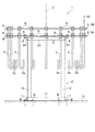
本発明の第一実施形態に係る柱用アンカーボルトの位置決め治具及び鋼製柱脚部の施工方法について図面を用いて詳細に説明する。図1及び図2に示すように、本実施形態に係る柱用アンカーボルトの位置決め治具1は、アンカーフレーム2と、2枚で構成されたテンプレート3と、複数の柱用アンカーボルト4とで主に構成されている。柱用アンカーボルトの位置決め治具1は、鋼製柱41(図9参照)に連結される複数の柱用アンカーボルト4の位置決めを行う治具である。
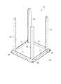
アンカーフレーム2は、柱用アンカーボルト4の高さ位置を定める部材である。アンカーフレーム2は、図3に示すように、基礎底盤10に設置される。基礎底盤10は、例えば、コンクリートで構築されている。アンカーフレーム2は、4本の底部材11と、4本の支持部材12とで構成されている。底部材11及び支持部材12の材料及び形状は特に制限されないが、本実施形態ではいずれも断面L字状の金属部材で形成されている。
底部材11は、平面視矩枠状に配置され、基礎底盤10にボルトBを介して固定されている。支持部材12は、隣り合う底部材11,11で構成された4つの内隅部に立設されている。支持部材12と底部材11とはボルト及びナット等の締結具で接続してもよいが、本実施形態では溶接されている。
[First embodiment]
A method for installing a column anchor bolt positioning jig and a steel column base according to the first embodiment of the present invention will be described in detail with reference to the drawings. As shown in FIGS. 1 and 2, a
The
The
テンプレート3は、図1に示すように、本実施形態では下部テンプレート3Aと、上部テンプレート3Bとで構成されている。下部テンプレート3A及び上部テンプレート3Bは、いずれもリング状かつ板状の金属部材である。下部テンプレート3A及び上部テンプレート3Bは、各柱用アンカーボルト4の上端側において、上下に離間して取り付けられている。下部テンプレート3Aと上部テンプレート3Bは同心となるように配置されている。下部テンプレート3A及び上部テンプレート3Bの中心を通る中心線Zは、鋼製柱41(図9参照)の柱心と重なる線である。
As shown in FIG. 1, the
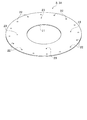
図4に示すように、下部テンプレート3Aの中央には、円形状の開口部21が形成されている。下部テンプレート3Aの外周縁には複数の貫通孔22が間隔をあけて配置されている。貫通孔22は、柱用アンカーボルト4が取り付けられる部位である。貫通孔22の数は特に制限されないが、本実施形態では16個形成されている。また、貫通孔22より内側に、4つの貫通孔23が形成されている。貫通孔23は、アンカーフレーム2が取り付けられる部位である。貫通孔23の個数は特に制限されるものではない。
As shown in FIG. 4, a
上部テンプレート3Bは、貫通孔23が形成されていないことを除いて、下部テンプレート3Aと同一である。なお、下部テンプレート3Aと上部テンプレート3Bは、汎用性を考慮して同一部材としてもよい(両方のテンプレートに貫通孔23を設けてもよい)。
図2に示すように、下部テンプレート3Aは、アンカーフレーム2の上端に連結部材24を介して接合されている。連結部材24は、断面L字状の金属部材である。連結部材24は、矩形枠状に四本配置されており、支持部材12に溶接されている。連結部材24は、ボルトB及びナットN等の締結具を介して下部テンプレート3Aに接続されている。下部テンプレート3Aは、アンカーフレーム2に対して着脱自在になっている。
The
As shown in FIG. 2, the
柱用アンカーボルト4は、図2に示すように、棒状を呈する金属部材である。柱用アンカーボルト4の上端側には、ナットNを螺合するためのネジ溝が形成されている。柱用アンカーボルト4の下端側(先端側)には、J字状を呈する湾曲部4aが形成されている。柱用アンカーボルト4は、下部テンプレート3A及び上部テンプレート3Bを貫通し、下部テンプレート3A及び上部テンプレート3Bの周方向に所定の間隔で取り付けられている。
柱用アンカーボルト4の本数は適宜設定すればよいが、本実施形態では16本用いている。柱用アンカーボルト4のうち、一本だけ上端部の長さ寸法が大きい部材を用いている(符号4X参照)。当該柱用アンカーボルト4Xは、鋼製柱41(図9参照)を建て込む際に、鋼製柱41を案内する機能を備えている。
As shown in FIG. 2, the
The number of
柱用アンカーボルト4のうち下部テンプレート3Aよりも上方は、鋼製柱41(図9参照)に連結される部位である。柱用アンカーボルト4の下端側は打設されるコンクリートに定着し、埋設される部位である。各柱用アンカーボルト4の湾曲部4aは、テンプレート3の中心線Z方向に向けて配置されている。下部テンプレート3A及び上部テンプレート3Bは、柱用アンカーボルト4に螺合された一対のナットN,Nによって挟持されている。
Above the
次に、本実施形態の鋼製柱脚部の施工方法について説明する。鋼製柱脚部の施工方法は、アンカーフレーム設置工程と、下部テンプレート取付工程と、柱用アンカーボルト取付工程と、上部テンプレート取付工程と、配筋工程と、コンクリート打設工程と、補強層形成工程と、テンプレート取外し工程と、建込み工程と、を行う。
アンカーフレーム設置工程は、図3に示すように、基礎底盤10にアンカーフレーム2を設置する工程である。アンカーフレーム設置工程では、4本の底部材11を矩形枠状に組み付けつつ、4本の支持部材12を立設する。底部材11は、ボルトBを介して基礎底盤10に固定する。
Next, a method of installing the steel column base of the present embodiment will be described. The construction method of the steel column base is as follows: anchor frame installation step, lower template installation step, pillar anchor bolt installation step, upper template installation step, reinforcing arrangement step, concrete placing step, and reinforcement layer formation. A process, a template removing process, and a building process are performed.
The anchor frame installation step is a step of installing the
下部テンプレート取付工程は、図5に示すように、アンカーフレーム2の上端に下部テンプレート3Aを取り付ける工程である。下部テンプレート取付工程では、支持部材12の上端に4本の連結部材24を矩形枠状に溶接する。そして、連結部材24の上に下部テンプレート3Aを載置し、連結部材24と下部テンプレート3AとをボルトB及びナットNで締結する。下部テンプレート3Aは、本実施形態では4箇所で接合する。
柱用アンカーボルト取付工程は、図6に示すように、下部テンプレート3Aに柱用アンカーボルト4を取り付ける工程である。柱用アンカーボルト取付工程では、下部テンプレート3Aの各貫通孔22に各柱用アンカーボルト4を挿入し、一対のナットN,Nで挟持する。また、このとき、各柱用アンカーボルト4の湾曲部4aは、中心線Z方向に向くように取り付ける。
The lower template attaching step is a step of attaching the
The pillar anchor bolt attaching step is a step of attaching the
上部テンプレート取付工程は、図7に示すように、柱用アンカーボルト4に上部テンプレート3Bを取り付ける工程である。上部テンプレート取付工程では、上部テンプレート3Bの各貫通孔22に各柱用アンカーボルト4を挿入し、一対のナットN,Nで挟持する。上部テンプレート3Bは、下部テンプレート3Aから上方に所定の距離で離間させる。これにより、柱用アンカーボルトの位置決め治具1が形成される。
The upper template attaching step is a step of attaching the
配筋工程は、柱用アンカーボルトの位置決め治具1の周囲に鉄筋を配筋する工程である。配筋工程では、横筋、縦筋及びフープ筋を配筋する。図面上では、鉄筋の描画を省略している。横筋は、アンカーフレーム2の支持部材12の下部において、格子状に配筋する。縦筋は、L字状を呈する鉄筋を用いる。縦筋は、テンプレート3の周囲に所定の間隔をあけて複数本配筋する。縦筋の上端は、柱用アンカーボルト4の上端よりも上方に位置する長さに設定する。フープ筋は、縦筋の外周に配筋する。フープ筋は、略円形状を呈する。フープ筋は、所定の間隔をあけて高さ方向に複数本配筋する。
The reinforcing arrangement step is a step of arranging reinforcing bars around the
コンクリート打設工程は、図8に示すように、アンカーフレーム2及び柱用アンカーボルト4の周囲にコンクリートCを打設して基礎部40(図9参照)を形成する工程である。コンクリート打設工程では、供給管Kを用いてコンクリートCを打設する。コンクリート打設工程では、本実施形態では、下部テンプレート3Aの近傍となる高さ位置までコンクリートCを打設する。本実施形態では、コンクリート打設工程後に下部テンプレート3A及び上部テンプレート3Bを取り外すため、連結部材24がコンクリートCに接触しない位置までコンクリートCを打設する。
補強層形成工程は、打設して硬化した後の基礎部40の上端と下部テンプレート3Aとの間に所定の厚さの補強層31(図9参照)を形成する工程である。補強層形成工程では、コンクリートCの上端と下部テンプレート3Aとの間の空間に、グラウト材(無収縮モルタル)を圧入する。これにより、補強層31が形成される。なお、補強層31は省略してもよい。
テンプレート取外し工程は、下部テンプレート3A及び上部テンプレート3Bを柱用アンカーボルト4から取り外す工程である。
建込み工程は、図9に示すように、柱用アンカーボルト4に鋼製柱41を接続する工程である。建込み工程では、鋼製柱41のフランジ42に形成された各貫通孔(図示省略)を各柱用アンカーボルト4に挿入しナットNて締結する。以上により、基礎部40に鋼製柱41が連結される。
なお、鋼製柱脚部の施工方法は、前記した工程順に限定されるものではない。例えば、補強層形成工程は、建込み工程を行って柱用アンカーボルト4と鋼製柱41のフランジ42とを連結した後、基礎部40とフランジ42との間に設けた隙間にグラウト材を圧入して補強層を形成してもよい。
As shown in FIG. 8, the concrete placing step is a step of placing concrete C around the
The reinforcing layer forming step is a step of forming a reinforcing layer 31 (see FIG. 9) having a predetermined thickness between the upper end of the
The template removing step is a step of removing the
The installation step is a step of connecting the
In addition, the construction method of the steel column base is not limited to the above-described process order. For example, in the reinforcing layer forming step, after the building step is performed to connect the
以上説明したアンカーボルトの位置決め治具1及び鋼製柱脚部の施工方法によれば、柱用アンカーボルト4の上端側が下部テンプレート3A及び上部テンプレート3Bによって上下方向に二点で支持される。これにより、コンクリートCを打設する際に、柱用アンカーボルト4が傾斜するのを防ぐことができる。また、柱用アンカーボルト4が傾斜するのを防ぐことで、鋼製柱41の建込み精度を高めることができる。
また、本実施形態では、柱用アンカーボルト4の上端側に下部テンプレート3A及び上部テンプレート3Bに取り付ける構造であるため、下部テンプレート3Aが埋設されない高さ位置までコンクリートCを打設した後、下部テンプレート3A及び上部テンプレート3Bを取り外し、当該下部テンプレート3A及び上部テンプレート3Bを再利用することができる。
また、本実施形態では、特殊な部品を用いることなく、少ない部品で簡易に柱用アンカーボルトの位置決め治具1を構成することができるため、低コストで容易に施工することができる。
According to the anchor
Moreover, in this embodiment, since it is the structure attached to the
Further, in this embodiment, the
また、本実施形態では、柱用アンカーボルト4を中心線Zを中心とした円上に複数本形成し、柱用アンカーボルト4の下端側に形成された湾曲部4aを中心線Z方向に向けて配設している。これにより、コンクリートCを柱用アンカーボルト4により強固にかつバランスよく定着させることができる。
また、グラウト材(無収縮モルタル)からなる補強層31を形成することにより、鋼製柱41を支える台座部分の収縮を防ぐことができる。これにより、鋼製柱41の沈下を防ぐことができる。
また、テンプレート3は、中央部分に開口部21のない構成であってもよいが、本実施形態のように開口部21が形成されていることにより、コンクリート打設工程の際に、特に、テンプレート3の下部のコンクリートCの充填状況を確認することができる。これにより、密実な基礎部40を形成することができる。
Further, in the present embodiment, a plurality of
Further, by forming the reinforcing
The
また、特許文献2の構成では、下部テンプレートが柱用アンカーボルトの下部に取り付けられるとともに、打設するコンクリート内に埋設される構成である。そのため、柱用アンカーボルトの周囲に鉄筋を配筋する作業が困難となる。これに対し、本実施形態では、柱用アンカーボルト4の上端側を下部テンプレート3A及び上部テンプレート3Bで取り付ける構成であり、柱用アンカーボルト4の下部にはテンプレートを配置しない。これにより、鉄筋の配筋作業を容易に行うことができる。
Further, in the configuration of
[第二実施形態]
次に、本発明の第二実施形態について説明する。図10は、本発明の第二実施形態に係る柱用アンカーボルトの位置決め治具1Aを示す斜視図である。図10に示すように、第二実施形態に係る柱用アンカーボルトの位置決め治具1Aは、アンカーフレーム2と、テンプレート3’と、複数の柱用アンカーボルト4とで主に構成されている。第二実施形態に係る柱用アンカーボルトの位置決め治具1Aは、テンプレート3’の形状が第一実施形態と相違する。第二実施形態に係る説明では、第一実施形態と共通する部分については説明を省略する。
[Second embodiment]
Next, a second embodiment of the present invention will be described. FIG. 10 is a perspective view showing a positioning jig 1A for a column anchor bolt according to a second embodiment of the present invention. As shown in FIG. 10, a positioning jig 1A for a column anchor bolt according to the second embodiment mainly includes an
テンプレート3’は、下部テンプレート3A’と、上部テンプレート3B’とで構成されている。下部テンプレート3A’及び上部テンプレート3B’は、平面視矩形枠状を呈する金属部材である。下部テンプレート3A’及び上部テンプレート3B’は、一体形成されていてもよいし、例えば、チャンネル材のような複数の金属部材を接続して形成してもよい。下部テンプレート3A’及び上部テンプレート3B’は、柱用アンカーボルト4の上端側に、上下方向に間隔をあけて取り付けられている。下部テンプレート3A’及び上部テンプレート3B’には、柱用アンカーボルト4を挿入するための貫通孔が柱用アンカーボルト4の本数に応じて形成されている。また、下部テンプレート3A’には、アンカーフレーム2を取り付けるための貫通孔が複数個形成されている。
このような柱用アンカーボルトの位置決め治具1A及び柱用アンカーボルトの位置決め治具1Aを用いた鋼製柱脚部の施工方法によっても、第一実施形態と略同等の効果を奏することができる。また、柱用アンカーボルトの位置決め治具1Aは、テンプレート3’が矩形枠状を呈するため、鋼製柱が角柱である場合に好適である。
The template 3 'includes a
The same effect as that of the first embodiment can be obtained by the method for constructing the steel column base using the positioning jig 1A for the column anchor bolt and the positioning jig 1A for the column anchor bolt. . Moreover, the positioning jig 1A of the anchor bolt for a pillar is suitable when the steel pillar is a prism because the template 3 'has a rectangular frame shape.
以上本発明の実施形態について説明したが、本発明の趣旨に反しない範囲において、適宜設計変更が可能である。例えば、本実施形態では上部テンプレート3B(3B’)を一枚設ける構成としたが、上部テンプレート3B(3B’)を複数枚設けてもよい。
また、本実施形態では、一対のナットN,Nで柱用アンカーボルト4に対してテンプレート3を挟持する構成としたが、他の締結具を用いて取り付けてもよい。また、本実施形態では、テンプレート3(3’)に貫通孔22を設けて柱用アンカーボルト4を挿入する構成としたが、貫通孔22を設けずテンプレート3の内縁又は外縁に柱用アンカーボルト4を取り付ける構成としてもよい。
Although the embodiments of the present invention have been described above, design changes can be made as appropriate without departing from the spirit of the present invention. For example, in this embodiment, one
In the present embodiment, the
また、本実施形態では、下部テンプレート3A(3A’)とアンカーフレーム2とを着脱自在に接続したが、下部テンプレート3A(3A’)とアンカーフレーム2とを溶接してもよい。この場合、コンクリート打設工程の際に、下部テンプレート3Aが埋設する位置までコンクリートCを打設する。
In the present embodiment, the
また、本実施形態では、テンプレート3の外縁側のみの周方向に亘って複数の柱用アンカーボルト4を配置したが、内縁側にも周方向に亘って複数の柱用アンカーボルト4を配置してもよい。この場合、鋼製柱41の柱隅部(外縁側)に対応した柱用アンカーボルト4には、大きな引き抜き力が作用するため、十分な定着性能、定着長さが必要である。一方、鋼製柱41の柱芯側(内縁側)の柱用アンカーボルト4には、地震時に発生する繰り返し水平荷重による引き抜き力は柱隅部より小さく、比較的に小さな定着性能、定着長さで対応可能である。本実施形態では、例えば、各柱用アンカーボルト4の埋設長さを容易に変化させることができるため、柱用アンカーボルト4の埋設長さを柱隅部側は長く、柱芯側は短くする作業を容易に行うことができる。また、本実施形態に係る鋼製柱脚部の施工方法では、現場で柱用アンカーボルトの位置決め治具1(1A)を構築したが、他の場所で予め柱用アンカーボルトの位置決め治具1(1A)を構築しておき、現場に設置してもよい。
Further, in the present embodiment, the plurality of
1 柱用アンカーボルトの位置決め治具
2 アンカーフレーム
3 テンプレート
3A 下部テンプレート
3B 上部テンプレート
4 柱用アンカーボルト
4a 湾曲部
10 基礎底盤
40 基礎部
41 鋼製柱
B ボルト
C コンクリート
N ナット
DESCRIPTION OF
Claims (3)
当該柱用アンカーボルトの上端側において上下に間隔をあけて配設された複数のテンプレートと、
基礎底盤に固定され前記柱用アンカーボルトの高さ位置を定めるアンカーフレームと、を備えた柱用アンカーボルトの位置決め治具を含む鋼製柱の脚部構造であって、
前記テンプレートは、前記アンカーフレームに取り付けられる下部テンプレートと、前記下部テンプレートの上方に離間して配設された単数又は複数の上部テンプレートと、を有し、前記下部テンプレート及び前記上部テンプレートは、前記柱用アンカーボルトに螺合された一対のナットでそれぞれ挟持されており、
前記アンカーフレーム及び前記柱用アンカーボルトは、前記下部テンプレートより下方の所定の高さ位置まで打設される基礎部のコンクリートに埋設されており、
前記基礎部のコンクリートと前記鋼製柱のフランジとの間に補強層が形成されていることを特徴とする鋼製柱の脚部構造。 And a pillar for the anchor bolt that will be connected to the lower end of the steel columns,
A plurality of templates arranged at intervals above and below at the upper end side of the pillar anchor bolt ,
Anchor frame fixed to the base floor to determine the height position of the pillar anchor bolt, and a leg structure of a steel pillar including a positioning jig for the pillar anchor bolt having:
The template includes a lower template attached to the anchor frame, and one or more upper templates spaced apart above the lower template, wherein the lower template and the upper template are are clamped respectively to use anchor bolts screwed a pair of nuts,
The anchor frame and the anchor bolts for the pillars are embedded in concrete of a foundation part that is driven to a predetermined height position below the lower template,
A leg structure for a steel column, wherein a reinforcing layer is formed between the concrete of the foundation and the flange of the steel column .
前記柱用アンカーボルトの下端側に形成された湾曲部が、前記中心線方向に向けて配設されていることを特徴とする請求項1に記載の鋼製柱の脚部構造。 The pillar anchor bolts are arranged in plurality around the center line of the template,
The leg structure of a steel column according to claim 1 , wherein a curved portion formed at a lower end side of the column anchor bolt is disposed toward the center line.
前記アンカーフレームに下部テンプレートを取り付ける工程と、
前記下部テンプレートに前記柱用アンカーボルトの上端側を取り付ける工程と、
前記柱用アンカーボルトに、前記下部テンプレートから上方に離間するように単数又は複数の上部テンプレートを取り付ける工程と、
前記アンカーフレーム及び前記柱用アンカーボルトの周囲に、前記下部テンプレートより下方の所定の高さ位置までコンクリートを打設する工程と、
前記下部テンプレート及び前記上部テンプレートを前記柱用アンカーボルトから取り外す工程と、
前記柱用アンカーボルトと鋼製柱の脚部を連結する工程と、を含むことを特徴とする鋼製柱脚部の施工方法。 A step of installing an anchor frame that determines the height position of the anchor bolts for the pillar on the foundation bottom;
Attaching a lower template to the anchor frame;
Attaching the upper end side of the pillar anchor bolt to the lower template,
A step of attaching one or more upper templates to the column anchor bolts so as to be separated upward from the lower template,
A step of casting concrete around the anchor frame and the column anchor bolts to a predetermined height below the lower template ;
Removing the lower template and the upper template from the column anchor bolts;
Connecting the column anchor bolt and the leg of the steel column.
Priority Applications (1)
| Application Number | Priority Date | Filing Date | Title |
|---|---|---|---|
| JP2015187795A JP6632290B2 (en) | 2015-09-25 | 2015-09-25 | Steel column leg structure and steel column leg construction method |
Applications Claiming Priority (1)
| Application Number | Priority Date | Filing Date | Title |
|---|---|---|---|
| JP2015187795A JP6632290B2 (en) | 2015-09-25 | 2015-09-25 | Steel column leg structure and steel column leg construction method |
Publications (2)
| Publication Number | Publication Date |
|---|---|
| JP2017061803A JP2017061803A (en) | 2017-03-30 |
| JP6632290B2 true JP6632290B2 (en) | 2020-01-22 |
Family
ID=58429953
Family Applications (1)
| Application Number | Title | Priority Date | Filing Date |
|---|---|---|---|
| JP2015187795A Active JP6632290B2 (en) | 2015-09-25 | 2015-09-25 | Steel column leg structure and steel column leg construction method |
Country Status (1)
| Country | Link |
|---|---|
| JP (1) | JP6632290B2 (en) |
Families Citing this family (3)
| Publication number | Priority date | Publication date | Assignee | Title |
|---|---|---|---|---|
| CN209129333U (en) * | 2018-07-27 | 2019-07-19 | 中建五局第三建设有限公司 | A kind of dedicated adjustable formwork of floor construction |
| CN114718308A (en) * | 2022-05-19 | 2022-07-08 | 浙江万寿建筑工程有限公司 | Construction method for frame column base sealing mold |
| JP7378861B1 (en) | 2023-02-28 | 2023-11-14 | 小川工業株式会社 | Concrete template and method for manufacturing concrete template |
-
2015
- 2015-09-25 JP JP2015187795A patent/JP6632290B2/en active Active
Also Published As
| Publication number | Publication date |
|---|---|
| JP2017061803A (en) | 2017-03-30 |
Similar Documents
| Publication | Publication Date | Title |
|---|---|---|
| KR101556545B1 (en) | Method for constructing using a double wall Precast Concrete | |
| JP6632290B2 (en) | Steel column leg structure and steel column leg construction method | |
| JP2018115489A (en) | Anchor frame and method of building steel frame structure using the same | |
| JP6382661B2 (en) | Column base structure of steel column and method of standing steel column | |
| JP2009228212A (en) | Device for concrete construction | |
| JP2015101823A (en) | Positioning member and erection method | |
| JP7194531B2 (en) | Seismic isolation upper foundation structure and manufacturing method thereof, footing structure, and seismic isolation foundation construction method | |
| JP6388840B2 (en) | Column beam connection structure and its construction method | |
| JP2006322154A (en) | Foundation construction method of building | |
| JP2016205051A (en) | Construction method for structure | |
| JP5912194B1 (en) | Construction method of wooden building and basic member used in the construction method | |
| JP6435218B2 (en) | Fixing method of joint steel frame in composite structure, construction method and joint structure of joint, anchor bolt fixing jig | |
| JP5345238B1 (en) | Construction method of base-isolated base structure and base-isolated base structure | |
| JP4625692B2 (en) | Building construction method of base-isolated structure with laminated rubber bearing | |
| JP6849491B2 (en) | Exposed column base structure of steel columns and its construction method | |
| JP2021195834A (en) | Column base anchor structure, trestle, and design method for column base anchor structure | |
| JP6102614B2 (en) | Building basic structure | |
| JP6829631B2 (en) | Construction method of column base, reinforcement method of existing column base | |
| JPH0533351A (en) | Steel column base of steel frame structure and execution thereof | |
| JP2008115539A (en) | Flat plate construction method | |
| JP6357332B2 (en) | Construction method of seismic isolation foundation | |
| JP5291643B2 (en) | How to build a wall | |
| JP7165548B2 (en) | Seismic isolation foundation structure and its construction method | |
| JP7017033B2 (en) | Foundation structure and foundation structure construction method | |
| JP6300228B2 (en) | Flat slab structure |
Legal Events
| Date | Code | Title | Description |
|---|---|---|---|
| A621 | Written request for application examination |
Free format text: JAPANESE INTERMEDIATE CODE: A621 Effective date: 20180619 |
|
| A977 | Report on retrieval |
Free format text: JAPANESE INTERMEDIATE CODE: A971007 Effective date: 20190424 |
|
| A131 | Notification of reasons for refusal |
Free format text: JAPANESE INTERMEDIATE CODE: A131 Effective date: 20190514 |
|
| A521 | Written amendment |
Free format text: JAPANESE INTERMEDIATE CODE: A523 Effective date: 20190612 |
|
| TRDD | Decision of grant or rejection written | ||
| A01 | Written decision to grant a patent or to grant a registration (utility model) |
Free format text: JAPANESE INTERMEDIATE CODE: A01 Effective date: 20191119 |
|
| A61 | First payment of annual fees (during grant procedure) |
Free format text: JAPANESE INTERMEDIATE CODE: A61 Effective date: 20191210 |
|
| R150 | Certificate of patent or registration of utility model |
Ref document number: 6632290 Country of ref document: JP Free format text: JAPANESE INTERMEDIATE CODE: R150 |