JP7194531B2 - Seismic isolation upper foundation structure and manufacturing method thereof, footing structure, and seismic isolation foundation construction method - Google Patents

Seismic isolation upper foundation structure and manufacturing method thereof, footing structure, and seismic isolation foundation construction method Download PDF

Info

Publication number
JP7194531B2
JP7194531B2 JP2018150515A JP2018150515A JP7194531B2 JP 7194531 B2 JP7194531 B2 JP 7194531B2 JP 2018150515 A JP2018150515 A JP 2018150515A JP 2018150515 A JP2018150515 A JP 2018150515A JP 7194531 B2 JP7194531 B2 JP 7194531B2
Authority
JP
Japan
Prior art keywords
seismic isolation
foundation structure
concrete
bag
reinforcing bar
Prior art date
Legal status (The legal status is an assumption and is not a legal conclusion. Google has not performed a legal analysis and makes no representation as to the accuracy of the status listed.)
Active
Application number
JP2018150515A
Other languages
Japanese (ja)
Other versions
JP2020026634A (en
Inventor
太郎 中川
毅洋 東
靖史 三浦
泰之 福島
大輔 角田
博之 塩田
徳彦 江藤
勇人 南部
仁 佐々木
直樹 高森
Current Assignee (The listed assignees may be inaccurate. Google has not performed a legal analysis and makes no representation or warranty as to the accuracy of the list.)
Fujita Corp
Original Assignee
Fujita Corp
Priority date (The priority date is an assumption and is not a legal conclusion. Google has not performed a legal analysis and makes no representation as to the accuracy of the date listed.)
Filing date
Publication date
Application filed by Fujita Corp filed Critical Fujita Corp
Priority to JP2018150515A priority Critical patent/JP7194531B2/en
Publication of JP2020026634A publication Critical patent/JP2020026634A/en
Application granted granted Critical
Publication of JP7194531B2 publication Critical patent/JP7194531B2/en
Active legal-status Critical Current
Anticipated expiration legal-status Critical

Links

Images

Description

本発明の一実施形態は、免震装置の上に設けられる基礎構造に関する。 One embodiment of the present invention relates to a foundation structure provided on top of a seismic isolation device.

ビルディング等の建造物の耐震性を高めるために、その基礎部分には免震構造が設けられている。免震構造としては、例えば、下部基礎上に設けられた免震装置の上に、プレキャストコンクリート盤(PCa盤)を配置し、アンカー部材により固定された構造(特許文献1参照)、免震装置上に、鉄筋を定着するための定着部が備えられたプレキャストコンクリート盤を設置した構造(特許文献2参照)、主脚部を固定するための鉄筋を埋め込んだプレキャストコンクリート盤を免震装置上に設けた構造(特許文献3参照)、が開示されている。 In order to improve the earthquake resistance of structures such as buildings, a base isolation structure is provided at the foundation. As a seismic isolation structure, for example, a structure in which a precast concrete board (PCa board) is placed on a seismic isolation device provided on a lower foundation and fixed by an anchor member (see Patent Document 1), a seismic isolation device A structure in which a precast concrete board with fixing parts for fixing reinforcing bars is installed on the top (see Patent Document 2), and a precast concrete board with embedded reinforcing bars for fixing the main legs is placed on the seismic isolation device. A structure provided (see Patent Document 3) is disclosed.

特開2012-067524号公報(特許第5737554号)Japanese Patent Application Laid-Open No. 2012-067524 (Patent No. 5737554) 特開2014-091943号公報(特許第5345238号)Japanese Patent Application Laid-Open No. 2014-091943 (Patent No. 5345238) 特開2011-047201号公報(特許第5232106号)Japanese Patent Application Laid-Open No. 2011-047201 (Patent No. 5232106)

免震装置の上にフーチングと呼ばれる建物の基礎構造を形成するためには、建築現場でコンクリートを打設する必要がある。コンクリートを打設するには、型枠を設置し、型枠用サポートで支持する必要がある。さらに、フーチングと基礎梁の鉄筋が混在し、それに加えてフーチング内に補強筋を介在させることで配筋作業が繁雑となり、施工性が低下するという問題がある。また、免震上部基礎構造を用いて作製されるフーチング構造体において耐震性を向上させることが求められている。 In order to form the foundation structure of the building, called a footing, on the seismic isolation device, it is necessary to cast concrete at the construction site. To pour concrete, formwork must be installed and supported by formwork supports. Furthermore, the reinforcing bars of the footing and the foundation beam are mixed together, and in addition, the interposition of the reinforcing bars in the footing complicates the work of arranging the reinforcing bars, thereby lowering the workability. In addition, it is required to improve the earthquake resistance of the footing structure manufactured using the seismic isolation upper foundation structure.

本発明の目的の一つは、このような課題を解決するための免震上部基礎構造を提供することにある。 One of the objects of the present invention is to provide a seismic isolation upper foundation structure for solving such problems.

本発明の一実施形態に係る免震上部基礎構造は、貫通孔を有するベースプレートと、ベースプレート上のコンクリート部と、コンクリート部に埋設されるベース筋と、貫通孔に合わせて前記ベースプレート上に配置され、上部がコンクリート部から露出される複数の袋状ナットと、複数の袋状ナットのそれぞれの上端に設けられた定着板と、下部がコンクリート部に埋設され、上部がコンクリート部から露出する複数の補強筋と、を有する。 A seismic isolation upper foundation structure according to one embodiment of the present invention includes a base plate having a through hole, a concrete portion on the base plate, a base reinforcement embedded in the concrete portion, and arranged on the base plate in alignment with the through hole. , a plurality of bag-shaped nuts whose upper portions are exposed from the concrete portion; fixing plates provided at the upper ends of the plurality of bag-shaped nuts; and a plurality of lower portions embedded in the concrete portion and upper portions exposed from the concrete portion. and a reinforcing bar.

本発明の一実施形態に係る免震上部基礎構造の作製方法は、ベース筋を配筋し、免震装置のフランジ形状に合わせて上部に定着板が設けられた袋状ナットを立設し、袋状ナットに対応して補強筋を配筋し、ベース筋、袋状ナット、及び補強筋を囲むように型枠を配置し、定着板、袋状ナット及び補強筋の上部が露出するように型枠内にコンクリートを打設することを含み、補強筋は、袋状ナットに隣接し、かつ離間するように配筋することを含む。 A method for manufacturing a seismic isolation upper foundation structure according to an embodiment of the present invention includes: arranging base reinforcement; Reinforcing bars are arranged corresponding to the bag-like nut, and a formwork is arranged so as to surround the base bar, bag-like nut, and reinforcing bars, so that the fixing plate, bag-like nut, and upper parts of the reinforcing bars are exposed. Concrete is poured into the formwork, and the reinforcing bars are placed adjacent to and spaced apart from the bag nuts.

本発明の一実施形態によれば、免震上部基礎構造において、袋状ナットに隣接して補強筋を配置することで、耐震性を高めることができる。 According to one embodiment of the present invention, in the seismic isolation upper foundation structure, the seismic resistance can be improved by arranging reinforcing bars adjacent to the bag-shaped nuts.

本発明の一実施形態に係る免震上部基礎構造を示し、(A)は平面図であり、(B)は断面模式図である。BRIEF DESCRIPTION OF THE DRAWINGS The seismic isolation upper foundation structure which concerns on one Embodiment of this invention is shown, (A) is a top view, (B) is a cross-sectional schematic diagram. 本発明の一実施形態に係る免震上部基礎構造の断面模式図を示す。The cross-sectional schematic diagram of the seismic isolation upper foundation structure which concerns on one Embodiment of this invention is shown. 本発明の一実施形態に係る免震上部基礎構造の補強筋の取り付け構造を示す断面模式図である。It is a cross-sectional schematic diagram which shows the attachment structure of the reinforcing bar of the seismic isolation upper foundation structure which concerns on one Embodiment of this invention. 本発明の一実施形態に係る免震上部基礎構造の立ち上がり部と袋状ナット及び定着板、並びに補強筋の詳細を示す断面図である。FIG. 4 is a cross-sectional view showing details of a rising portion, a bag-like nut, a fixing plate, and reinforcing bars of the seismic isolation upper foundation structure according to one embodiment of the present invention. 本発明の一実施形態に係る免震上部基礎構造に用いられる補強筋の一例を示す。1 shows an example of reinforcing bars used in the seismic isolation upper foundation structure according to one embodiment of the present invention. 本発明の一実施形態に係る免震上部基礎構造の作製方法を説明する断面図であり、(A)はベースプレート上に袋状ナットが配置され、ベース筋及び補強筋が配筋され、型枠が配置された状態を示す平面図であり、(B)はその断面模式図を示す。FIG. 4A is a cross-sectional view illustrating a method of manufacturing a seismic isolation upper foundation structure according to an embodiment of the present invention, and FIG. is a plan view showing a state in which are arranged, and (B) shows a schematic cross-sectional view thereof. 本発明の一実施形態に係る免震上部基礎構造の作製方法を説明する断面図であり、(A)は内側型枠の下端までコンクリートが打設される段階、(B)は外側型枠と内側型枠の間にコンクリートが打設される段階を示す。1 is a cross-sectional view illustrating a method for producing a seismic isolation upper foundation structure according to an embodiment of the present invention, where (A) is the stage where concrete is placed to the lower end of the inner formwork, and (B) is the outer formwork and Fig. 4 shows the stage at which concrete is poured between the inner formwork; 本発明の一実施形態に係るフーチング構造体の断面模式図を示す。1 shows a schematic cross-sectional view of a footing structure according to an embodiment of the present invention; FIG. 本発明の一実施形態に係る免震基礎の施工方法を説明する断面図であり、免震上部基礎構造を免震装置の上に設置する段階を示す。FIG. 4 is a cross-sectional view for explaining the construction method of the seismic isolation foundation according to one embodiment of the present invention, showing the stage of installing the seismic isolation upper foundation structure on the seismic isolation device. 本発明の一実施形態に係る免震基礎の施工方法を説明する断面図であり、免震上部基礎構造の上に梁主筋を配筋する段階を示す。FIG. 4 is a cross-sectional view for explaining the construction method of the seismic isolation foundation according to one embodiment of the present invention, showing a step of arranging main beam reinforcements on the seismic isolation upper foundation structure. 本発明の一実施形態に係る免震基礎の施工方法を説明する断面図であり、基礎梁を形成する段階を示す。FIG. 4 is a cross-sectional view illustrating a construction method for a seismic isolation foundation according to an embodiment of the present invention, showing a stage of forming foundation beams. 本発明の一実施形態に係る免震基礎構造の上に鉄骨基礎梁を設けた一態様を示す断面図である。1 is a cross-sectional view showing one mode in which a steel frame foundation beam is provided on a seismic isolation foundation structure according to one embodiment of the present invention. FIG. 本発明の一実施形態に係る免震上部基礎構造の上に基礎梁を設けた一態様を示す斜視図であり、(A)は基礎梁が鉄筋コンクリート製である場合を示し、(B)は基礎梁がH形鋼である場合を示す。BRIEF DESCRIPTION OF THE DRAWINGS Fig. 1 is a perspective view showing one mode in which foundation beams are provided on a seismic isolation upper foundation structure according to one embodiment of the present invention, (A) shows a case where the foundation beams are made of reinforced concrete, and (B) is a foundation; It shows the case where the beam is H-beam. 本発明の一実施形態に係る免震上部基礎構造を示し、(A)は平面図であり、(B)は断面模式図である。BRIEF DESCRIPTION OF THE DRAWINGS The seismic isolation upper foundation structure which concerns on one Embodiment of this invention is shown, (A) is a top view, (B) is a cross-sectional schematic diagram. 本発明の一実施形態に係る免震上部基礎構造を示し、(A)は平面図であり、(B)は断面模式図である。BRIEF DESCRIPTION OF THE DRAWINGS The seismic isolation upper foundation structure which concerns on one Embodiment of this invention is shown, (A) is a top view, (B) is a cross-sectional schematic diagram. 本発明の一実施形態に係る免震上部基礎構造の断面模式図を示す。The cross-sectional schematic diagram of the seismic isolation upper foundation structure which concerns on one Embodiment of this invention is shown. 本発明の一実施形態に係る免震上部基礎構造を示し、(A)は平面図であり、(B)は断面模式図である。BRIEF DESCRIPTION OF THE DRAWINGS The seismic isolation upper foundation structure which concerns on one Embodiment of this invention is shown, (A) is a top view, (B) is a cross-sectional schematic diagram. 本発明の一実施形態に係る免震上部基礎構造の作製方法を説明する断面図であり、(A)はベースプレート上に袋状ナットが配置され、ベース筋及び補強筋が配筋され、型枠が配置される段階、(B)は型枠の内側にコンクリートが打設される段階を示す。FIG. 4A is a cross-sectional view illustrating a method of manufacturing a seismic isolation upper foundation structure according to an embodiment of the present invention, and FIG. is placed, and (B) shows the step of placing concrete inside the formwork. 本発明の一実施形態に係る免震基礎の施工方法を説明する断面図であり、免震上部基礎構造を免震装置の上に設置する段階を示す。FIG. 4 is a cross-sectional view for explaining the construction method of the seismic isolation foundation according to one embodiment of the present invention, showing the stage of installing the seismic isolation upper foundation structure on the seismic isolation device. 本発明の一実施形態に係る免震基礎の施工方法を説明する断面図であり、免震上部基礎構造の上に梁主筋を配筋する段階を示す。FIG. 4 is a cross-sectional view for explaining the construction method of the seismic isolation foundation according to one embodiment of the present invention, showing a step of arranging main beam reinforcements on the seismic isolation upper foundation structure. 本発明の一実施形態に係る免震基礎の施工方法を説明する断面図であり、基礎梁を形成する段階を示す。FIG. 4 is a cross-sectional view illustrating a construction method for a seismic isolation foundation according to an embodiment of the present invention, showing a stage of forming foundation beams. 本発明の一実施形態に係る免震上部基礎構造を示し、(A)は平面図であり、(B)は断面模式図である。BRIEF DESCRIPTION OF THE DRAWINGS The seismic isolation upper foundation structure which concerns on one Embodiment of this invention is shown, (A) is a top view, (B) is a cross-sectional schematic diagram. 本発明の一実施形態に係る免震上部基礎構造の作製方法を説明する断面図であり、(A)は型枠上に袋状ナットが配置され、ベース筋及び補強筋が配筋される段階、(B)は(B)は型枠の内側にコンクリートが打設される段階を示す。It is a sectional view explaining the manufacturing method of the seismic isolation upper foundation structure according to one embodiment of the present invention, (A) is the stage where the bag-shaped nut is arranged on the formwork and the base reinforcement and the reinforcing reinforcement are arranged. , (B) shows the stage at which concrete is placed inside the formwork. 本発明の一実施形態に係る免震基礎の施工方法を説明する断面図であり、免震上部基礎構造を免震装置の上に設置する段階を示す。FIG. 4 is a cross-sectional view for explaining the construction method of the seismic isolation foundation according to one embodiment of the present invention, showing the stage of installing the seismic isolation upper foundation structure on the seismic isolation device. 本発明の一実施形態に係る免震基礎の施工方法を説明する断面図であり、免震上部基礎構造の上に梁主筋を配筋する段階を示す。FIG. 4 is a cross-sectional view for explaining the construction method of the seismic isolation foundation according to one embodiment of the present invention, showing a step of arranging main beam reinforcements on the seismic isolation upper foundation structure. 本発明の一実施形態に係る免震基礎の施工方法を説明する断面図であり、基礎梁を形成する段階を示す。FIG. 4 is a cross-sectional view illustrating a construction method for a seismic isolation foundation according to an embodiment of the present invention, showing a stage of forming foundation beams. 本発明の一実施形態に係る免震上部基礎構造の作製方法を説明する断面模式図を示す。The cross-sectional schematic diagram explaining the production method of the seismic isolation upper foundation structure which concerns on one Embodiment of this invention is shown.

以下、本発明の実施形態の内容を、図面等を参照しながら説明する。但し、本発明は多くの異なる態様を含み、以下に例示される実施形態の内容に限定して解釈されるものではない。図面は説明をより明確にするため、実際の態様に比べ、各部の幅、厚さ、形状等について模式的に表される場合があるが、それはあくまで一例であって、本発明の内容を限定するものではない。また、本明細書において、ある図面に記載されたある要素と、他の図面に記載されたある要素とが同一又は対応する関係にあるときは、同一の符号(又は符号として記載された数字の後にa、b等を付した符号)を付して、繰り返しの説明を適宜省略することがある。さらに各要素に対する「第1」、「第2」と付記された文字は、各要素を区別するために用いられる便宜的な標識であり、特段の説明がない限りそれ以上の意味を有さない。 Hereinafter, the contents of embodiments of the present invention will be described with reference to the drawings and the like. However, the present invention includes many different aspects and should not be construed as being limited to the content of the embodiments illustrated below. In order to make the description clearer, the drawings may schematically show the width, thickness, shape, etc. of each part compared to the actual embodiment, but this is only an example and does not limit the content of the present invention. not something to do. In addition, in this specification, when a certain element described in a certain drawing and a certain element described in another drawing are the same or have a corresponding relationship, the same reference numerals (or numbers Reference numerals such as a, b, etc. are attached later, and repeated description may be omitted as appropriate. In addition, the letters "first" and "second" for each element are convenient labels used to distinguish each element and have no further meaning unless otherwise specified. .

第1の実施形態:
本実施形態は、免震装置の上部に設けられる基礎構造(以下、「免震上部基礎構造」という。)の構成を示す。以下、本実施形態に係る免震上部基礎構造の構成及びその製造方法、並びに免震上部基礎構造を用いたフーチング構造体について説明する。
First embodiment:
This embodiment shows the configuration of a foundation structure (hereinafter referred to as "base isolation upper foundation structure") provided on the upper part of the seismic isolation device. Hereinafter, the structure of the seismic isolation upper foundation structure which concerns on this embodiment, its manufacturing method, and the footing structure using the seismic isolation upper foundation structure are demonstrated.

(1)免震上部基礎構造
図1(A)は、本実施形態に係る免震上部基礎構造100aの平面図を示し、図1(B)は、その断面構造の模式図を示す。免震上部基礎構造100aは、ベースプレート102、ベース筋116、コンクリート部106、袋状ナット112、袋状ナット112の上部に付された定着板114、及び補強筋115aを含んで構成される。
(1) Seismic Isolation Upper Foundation Structure FIG. 1(A) shows a plan view of a seismic isolation upper foundation structure 100a according to this embodiment, and FIG. 1(B) shows a schematic diagram of its cross-sectional structure. The seismic isolation upper foundation structure 100a includes a base plate 102, a base reinforcement 116, a concrete portion 106, a bag-like nut 112, a fixing plate 114 attached to the upper part of the bag-like nut 112, and a reinforcing bar 115a.

ベースプレート102は、複数の貫通孔104を有する。ベースプレート102における貫通孔104は、免震装置の上部フランジに形成されるアンカーボルトを挿通するための貫通孔に合わせて配置される。例えば、貫通孔104は、ベースプレート102の中心を円心として所定の半径を有する円周上の複数箇所に形成される。ベースプレート102は金属製であり、例えば、鋼鉄によって作製される。ベースプレート102の厚さは任意であるが、10mmから30mm、例えば20mmの厚さを有する。また、図1(A)は、ベースプレート102が矩形である場合を示すが、ベースプレート102の平面的な形状はこれに限定されず、他の多角形又は円形であってもよい。 Base plate 102 has a plurality of through holes 104 . The through-holes 104 in the base plate 102 are aligned with through-holes for inserting anchor bolts formed in the upper flange of the seismic isolation device. For example, the through-holes 104 are formed at a plurality of locations on a circle having a predetermined radius with the center of the base plate 102 as the center of the circle. The base plate 102 is metallic, for example made of steel. The thickness of the base plate 102 is arbitrary, but has a thickness of 10 mm to 30 mm, for example 20 mm. Moreover, although FIG. 1A shows a case where the base plate 102 is rectangular, the planar shape of the base plate 102 is not limited to this, and may be other polygonal or circular shapes.

袋状ナット112は、ベースプレート102上で貫通孔104の配置に合わせて複数個配置される。袋状ナット112の上部には、定着板114が設けられる。定着板114は平板状であり、先端が袋状ナット112の本体から水平に突出するように設けられる。図1(B)に示すように、袋状ナット112は、ベースプレート102上に立設するように設けられる。袋状ナット112は、あらかじめ溶接によってベースプレート102に固定されていてもよい。袋状ナット112を溶接でベースプレート102上に固定しておくことにより、精度良く配置することができ、免震上部基礎構造100aを免震装置上で安定的に保持することができる。ベースプレート102上の袋状ナット112は、下側部分がコンクリート部106に埋設され、上側部分がコンクリート部106から露出するように設けられる。 A plurality of bag-shaped nuts 112 are arranged on the base plate 102 according to the arrangement of the through holes 104 . A fixing plate 114 is provided above the bag-like nut 112 . The fixing plate 114 has a flat plate shape, and is provided so that the tip thereof horizontally protrudes from the main body of the bag-shaped nut 112 . As shown in FIG. 1B, the cap-shaped nut 112 is provided so as to stand on the base plate 102 . The bag-shaped nut 112 may be fixed to the base plate 102 by welding in advance. By fixing the bag-shaped nut 112 on the base plate 102 by welding, it can be arranged with high accuracy, and the seismic isolation upper foundation structure 100a can be stably held on the seismic isolation device. The bag-like nut 112 on the base plate 102 is provided so that the lower portion is embedded in the concrete portion 106 and the upper portion is exposed from the concrete portion 106 .

図1(A)及び図1(B)に示すように、コンクリート部106は、ベースプレート102の上面側に設けられる。図1(B)は、ベースプレート102の上面とコンクリート部106の底面が接するように設けられた形態を示す。また、図2に示すように、コンクリート部106は、ベースプレート102の上面及び側面を覆うように設けられていてもよい。ベースプレート102の上面及び側面が、コンクリート部106に埋設されるようにすることで、免震上部基礎構造100の底面を平坦化することができ、ベースプレート102とコンクリート部106との間に働くせん断力に対する耐性を高めることができる。 As shown in FIGS. 1A and 1B, the concrete portion 106 is provided on the upper surface side of the base plate 102 . FIG. 1B shows a configuration in which the top surface of the base plate 102 and the bottom surface of the concrete portion 106 are in contact with each other. Moreover, as shown in FIG. 2, the concrete portion 106 may be provided so as to cover the upper surface and side surfaces of the base plate 102 . By embedding the upper surface and side surfaces of the base plate 102 in the concrete portion 106, the bottom surface of the seismic isolation upper foundation structure 100 can be flattened, and the shear force acting between the base plate 102 and the concrete portion 106 can increase resistance to

図1(A)及び図1(B)に示すように、コンクリート部106は平板状であっても良いし、ベースプレート102と平行な平板部108と、平板部108から突出する立ち上がり部110を含んで構成されてもよい。立ち上がり部110は、コンクリート部106の周縁部に沿って平板部108の四方を囲むように設けられる。なお、平板部108と立ち上がり部110とは説明の都合上異なる部位として説明されるが、これらはコンクリート部106として一つの構造体を形成するように一体に形成されていてもよい。 As shown in FIGS. 1A and 1B, the concrete portion 106 may have a flat plate shape, and may include a flat plate portion 108 parallel to the base plate 102 and a rising portion 110 projecting from the flat plate portion 108. may consist of The rising portion 110 is provided along the peripheral portion of the concrete portion 106 so as to surround the four sides of the flat plate portion 108 . Although the flat plate portion 108 and the rising portion 110 are described as different portions for convenience of explanation, they may be integrally formed as the concrete portion 106 so as to form one structure.

ベース筋116は複数本がコンクリート部106の中に配筋される。コンクリート部106の表面からベース筋116までの厚さ(かぶり厚さ)は任意であるが、例えば、40mmから60mmの厚さを有する。複数のベース筋116は、コンクリート部106の中で袋状ナット112と干渉しないように、縦横に交差するように設けられる。複数のベース筋116は、交差部において適宜結束線で結束される。このように、免震上部基礎構造は、鉄筋コンクリートで形成される。 A plurality of base reinforcements 116 are arranged in the concrete portion 106 . Although the thickness (covering thickness) from the surface of the concrete portion 106 to the base reinforcement 116 is arbitrary, the thickness is, for example, 40 mm to 60 mm. A plurality of base reinforcements 116 are provided so as to intersect vertically and horizontally so as not to interfere with the bag-like nuts 112 in the concrete portion 106 . The plurality of base muscles 116 are appropriately bound with a binding wire at the intersection. Thus, the seismic isolation upper foundation structure is formed of reinforced concrete.

図1(B)に示すように、ベース筋116は、コンクリート部106の立ち上がり部110で上方に突出するように屈曲された形状を有する。別言すれば、複数のベース筋116のそれぞれは、平板部108で格子状に配筋されると共に、立ち上がり部110の上面から突出するように設けられることで、上方が開口した籠状の形状を有する。ベース筋116がコンクリート部106から突出する部分は、フーチング籠筋118とも呼ばれる。図1(B)に示すように、フーチング籠筋118の先端はU字状に折り曲げられていてもよい。 As shown in FIG. 1B, the base reinforcement 116 has a bent shape that protrudes upward at the rising portion 110 of the concrete portion 106 . In other words, each of the plurality of base reinforcements 116 is arranged in a grid pattern on the flat plate portion 108, and is provided so as to protrude from the upper surface of the rising portion 110, thereby forming a basket-like shape with an open top. have The part where the base reinforcement 116 protrudes from the concrete portion 106 is also called a footing cage reinforcement 118 . As shown in FIG. 1B, the tip of the footing basket reinforcement 118 may be bent in a U shape.

コンクリート部106は、ベース筋が上方へ突出するように屈曲していることで、立ち上がり部110の強度及び耐久性が高められている。図では示さないが、コンクリート部106には、立ち上がり部110に沿った枠状のベース筋が設けられていてもよい。なお、立ち上がり部110の高さは、後述されるように袋状ナット112及び定着板114、並びに補強筋115aの高さより高くなるように設けられる。また、立ち上がり部110の厚さは適宜設定されるが、少なくともフーチング籠筋118のかぶり厚さを満たす程度の幅を有する。 The concrete portion 106 is bent so that the base reinforcement protrudes upward, thereby increasing the strength and durability of the rising portion 110 . Although not shown in the drawing, the concrete portion 106 may be provided with a frame-shaped base reinforcement along the rising portion 110 . The height of the rising portion 110 is set to be higher than the heights of the bag-shaped nut 112, the fixing plate 114, and the reinforcing bars 115a, as will be described later. Also, the thickness of the rising portion 110 is appropriately set, but it has a width that satisfies at least the covering thickness of the basket reinforcing bars 118 of the footing.

袋状ナット112は、下側部分がコンクリート部106に埋設され、上側部分がコンクリート部106から露出するように設けられる。袋状ナット112の上部がコンクリート部106から露出することにより、定着板114も同様にコンクリート部106から露出する。補強筋115aは、少なくとも一部がコンクリート部106に埋設され、他の一部がコンクリート部106から露出するように設けられる。すなわち、補強筋115aは、下側部分がコンクリート部106に埋設され、上側部分がコンクリート部106から露出するように設けられる。 Bag-shaped nut 112 is provided such that its lower portion is embedded in concrete portion 106 and its upper portion is exposed from concrete portion 106 . By exposing the upper portion of bag-shaped nut 112 from concrete portion 106 , fixing plate 114 is also exposed from concrete portion 106 . Reinforcing bar 115 a is provided such that at least a portion thereof is embedded in concrete portion 106 and another portion thereof is exposed from concrete portion 106 . That is, the reinforcing bar 115 a is provided so that the lower portion is embedded in the concrete portion 106 and the upper portion is exposed from the concrete portion 106 .

図1(A)及び図1(B)は、閉鎖型の補強筋115aがコンクリート部106に設けられた態様を示す。図5(A-1)は、閉鎖型の補強筋115aの一例を示す。閉鎖型の補強筋115aは、鉄筋が矩形状に曲折された外観形状を有し、1本の鉄筋が一周曲げ回されて端部が一部重なる環状の形状を有している。また、図5(A-2)は、鉄筋の一端と他端が溶接されたフープ状の形状有する一例を示す。 FIGS. 1(A) and 1(B) show a mode in which a closed reinforcing bar 115a is provided in the concrete portion 106. FIG. FIG. 5(A-1) shows an example of a closed reinforcing bar 115a. The closed-type reinforcing bar 115a has an external shape in which a reinforcing bar is bent into a rectangular shape, and has an annular shape in which one reinforcing bar is bent around once and the ends are partially overlapped. FIG. 5A-2 shows an example of a hoop shape in which one end and the other end of a reinforcing bar are welded.

図1(A)及び図1(B)に示すように、補強筋115aは、袋状ナット112に隣接するように配置される。補強筋115aは、少なくとも一つが袋状ナット112と隣接して配置される。例えば、一つの袋状ナット112に対し、その両側を挟むように2つの補強筋115aが配置されていてもよい。なお、平面視において、補強筋115aは任意の方向に向けて配置することができる。例えば、図1(A)に示すように、平面視において、補強筋115aの一方は、ベース筋116に掛着するために、ベース筋116と垂直な方向に向けて配置することができる。また、補強筋115aの上部は、補強筋固定筋117に掛着される。補強筋固定筋117は、コンクリート部106から露出するように設けられる。 As shown in FIGS. 1A and 1B, the reinforcement 115a is arranged adjacent to the cap-like nut 112. As shown in FIG. At least one of the reinforcing bars 115 a is arranged adjacent to the cap-like nut 112 . For example, two reinforcing bars 115a may be arranged on both sides of one bag-like nut 112 . Note that the reinforcing bars 115a can be arranged in any direction in a plan view. For example, as shown in FIG. 1A, one side of the reinforcing bar 115a can be arranged in a direction perpendicular to the base bar 116 so as to hook onto the base bar 116 in plan view. Also, the upper part of the reinforcing bar 115 a is hooked to the reinforcing bar fixing bar 117 . The reinforcing bar fixing bar 117 is provided so as to be exposed from the concrete portion 106 .

図3は、補強筋115aの取り付け構造の詳細を示す。補強筋115aは、上側部分が補強筋固定筋117に掛けられ、下側部分がベース筋116に掛け渡されるように配置される。ベース筋116はコンクリート部106に埋め込まれ、補強筋固定筋117はコンクリート部106から露出し、平板部108の上方に配置される。ベース筋116及び補強筋固定筋117のこのような配置により、補強筋115aはコンクリート部106の表面から立設するように設けられる。 FIG. 3 shows the details of the mounting structure of the reinforcing bars 115a. The reinforcing bar 115 a is arranged so that the upper part is hung on the reinforcing bar fixing bar 117 and the lower part is hung on the base bar 116 . The base bar 116 is embedded in the concrete portion 106 , and the reinforcing bar fixing bar 117 is exposed from the concrete portion 106 and arranged above the flat plate portion 108 . Due to such arrangement of the base reinforcement 116 and the reinforcement reinforcement reinforcement 117 , the reinforcement reinforcement 115 a is provided so as to stand from the surface of the concrete portion 106 .

補強筋115aは、袋状ナット112に近接して配置される。補強筋115aは、袋状ナット112に接するのではなく、間隙をもって配置される。コンクリート部106は、ベース筋116、補強筋115aが配筋された状態で、袋状ナット112が立てられたベースプレート102上にコンクリートを打設することにより作製される。補強筋115aと袋状ナット112との間隔は、両者の間にコンクリートを構成するセメント及び骨材(粗骨材、細骨材)が十分に流れ込む程度の間隔を有していることが好ましい。例えば、補強筋115aと袋状ナット112との間隔は、30mm~40mm程度の間隔を有していることが好ましい。 The reinforcing bar 115 a is arranged close to the cap-shaped nut 112 . The reinforcing bars 115a are not in contact with the cap-shaped nut 112 but are arranged with a gap. The concrete portion 106 is produced by placing concrete on the base plate 102 on which the bag-like nut 112 is erected, with the base reinforcement 116 and the reinforcing reinforcement 115a arranged. It is preferable that the space between the reinforcing bar 115a and the bag-shaped nut 112 is such that the cement and aggregates (coarse aggregates and fine aggregates) that constitute the concrete flow sufficiently between them. For example, it is preferable that the spacing between the reinforcing bar 115a and the cap-like nut 112 is about 30 mm to 40 mm.

図4は、本発明の一実施形態に係る免震上部基礎構造100aにおける、立ち上がり部110、袋状ナット112、補強筋115aの詳細を示す。図4に示すように、袋状ナット112及び補強筋115aは、コンクリート部106の平板部108に配置される。袋状ナット112の上部及び定着板114、並びに補強筋115aは一部が平板部108から露出し、立ち上がり部110に囲まれるように配置される。図4は、補強筋115aが、鉄筋が矩形状に曲折された閉鎖型である場合を示す。補強筋115aは、袋状ナット112と並置され、平板部108の上面から略垂直に立ち上がるように設けられる。補強筋115aの上部は、補強筋固定筋117に掛けられる。補強筋固定筋117は平板部108の上方に配置され、複数の補強筋115aにより架設されるように設けられる。 FIG. 4 shows the details of the rising portion 110, the bag-shaped nut 112, and the reinforcing bars 115a in the seismic isolation upper foundation structure 100a according to one embodiment of the present invention. As shown in FIG. 4 , the bag-like nut 112 and the reinforcing bars 115 a are arranged on the flat plate portion 108 of the concrete portion 106 . The upper portion of the bag-shaped nut 112 , the fixing plate 114 and the reinforcing bar 115 a are partially exposed from the flat plate portion 108 and arranged so as to be surrounded by the rising portion 110 . FIG. 4 shows a case where the reinforcing bar 115a is a closed type in which the reinforcing bar is bent into a rectangular shape. The reinforcing bar 115 a is juxtaposed with the bag-shaped nut 112 and is provided so as to rise substantially vertically from the upper surface of the flat plate portion 108 . The upper part of the reinforcing bar 115 a is hung on the reinforcing bar fixing bar 117 . The reinforcing bar fixing bar 117 is arranged above the flat plate portion 108 and provided so as to be bridged by a plurality of reinforcing bars 115a.

袋状ナット112の上端には定着板114が設けられる。袋状ナット112は、定着板114の高さ(h1:平板部108の上面から定着板114の上面までの高さ)が、立ち上がり部110の高さ(h3:平板部108の上面から立ち上がり部110の上端までの高さ)より低くなるように設けられる。また、補強筋115aの高さ(h2:平板部108の上面から補強筋115aの上端までの高さ)は、定着板114の高さ(h1)より高く、立ち上がり部110の高さ(h1)より低くなるように設けられる。すなわち、袋状ナット112の定着板114までの高さh1と、補強筋115aの高さh2と、立ち上がり部110の高さh3とは、h1<h2<h3の関係が成立するように設けられる。 A fixing plate 114 is provided at the upper end of the bag-shaped nut 112 . The bag-like nut 112 is configured such that the height of the fixing plate 114 (h1: the height from the upper surface of the flat plate portion 108 to the upper surface of the fixing plate 114) is equal to the height of the rising portion 110 (h3: the height from the upper surface of the flat plate portion 108 to the rising portion). 110). Further, the height of the reinforcing bar 115a (h2: the height from the upper surface of the flat plate portion 108 to the upper end of the reinforcing bar 115a) is higher than the height (h1) of the fixing plate 114, and the height (h1) of the rising portion 110 is higher than the height (h1) of the fixing plate 114. provided to be lower. That is, the height h1 of the bag-shaped nut 112 to the fixing plate 114, the height h2 of the reinforcing bar 115a, and the height h3 of the rising portion 110 are provided so as to satisfy the relationship h1<h2<h3. .

図4において点線で示すように、免震上部基礎構造100aの上にはフーチング131及び基礎梁132が設けられる。基礎梁132が鉄筋コンクリートで作製される場合、コンクリート部106の上に鉄筋が配筋される。この場合、コンクリートのかぶり厚さを確保するため、梁主筋134を支持するスペーサ143が立ち上がり部110の上面に配置される。 As indicated by the dotted line in FIG. 4, a footing 131 and foundation beams 132 are provided on the seismic isolation upper foundation structure 100a. When the foundation beam 132 is made of reinforced concrete, reinforcing bars are arranged on the concrete portion 106 . In this case, a spacer 143 for supporting the beam main reinforcement 134 is arranged on the upper surface of the rising portion 110 in order to ensure the thickness of the concrete cover.

本実施形態に係る免震上部基礎構造100aは、袋状ナット112及び定着板114、並びに補強筋115aが、立ち上がり部110より突出しないように設けられることで、梁主筋134を配筋するときに袋状ナット112及び定着板114、並びに補強筋115aが干渉しないようにすることができる。別言すれば、免震上部基礎構造100aは、立ち上がり部110を有することで、袋状ナット112及び定着板114、並びに補強筋115aをコンクリート部106の表面(平板部108の上面)から突出して設けることができる。 In the seismic isolation upper foundation structure 100a according to the present embodiment, the bag-like nut 112, the fixing plate 114, and the reinforcing bar 115a are provided so as not to protrude from the rising portion 110, so that when the beam main bar 134 is arranged, It is possible to prevent the bag-like nut 112, the fixing plate 114, and the reinforcing bar 115a from interfering with each other. In other words, the seismic isolation upper foundation structure 100a has the rising portion 110 so that the bag-like nut 112, the fixing plate 114, and the reinforcing bar 115a protrude from the surface of the concrete portion 106 (upper surface of the flat plate portion 108). can be provided.

図4は、フーチング131が形成されたとき、アンカー部材(袋状ナット112、及び袋状ナットと締結されるアンカーボルト(図4では図示せず。))に引張応力が作用したときに発生し得るコーン状破壊面DFを点線で示す。補強筋115aは、コーン状破壊面DFを交差するように設けられる。免震上部基礎構造100aは、フーチング131が形成された場合において、コーン状破壊面DFと交差するように設けられた補強筋115aを有することで、コーン状破壊に対する耐性を高めることができる。 FIG. 4 shows that tensile stress is applied to the anchor members (cap-shaped nut 112 and anchor bolts (not shown in FIG. 4) fastened to the cap-shaped nut) when the footing 131 is formed. The resulting cone-shaped fracture surface DF is indicated by a dashed line. The reinforcing bar 115a is provided so as to cross the cone-shaped fracture surface DF. When the footing 131 is formed, the seismic isolation upper foundation structure 100a has reinforcing bars 115a provided so as to intersect with the cone-shaped failure surface DF, thereby increasing resistance to cone-shaped failure.

なお、本実施形態において、コンクリート部106は、免震装置の上で直接的にコンクリートが打設されて形成されたものではなく、プレキャスト製のものであることが好ましい。免震上部基礎構造100aがプレキャストされたコンクリートで形成されることで、建造物の基礎を形成する作業現場において、型枠を配置したり、作業現場を養生したりする手間が省略し、作業効率を向上させることが可能となる。 In the present embodiment, the concrete portion 106 is preferably precast rather than being formed by placing concrete directly on the seismic isolation device. By forming the seismic isolation upper foundation structure 100a with precast concrete, at the work site for forming the foundation of the building, the labor of arranging the formwork and curing the work site is omitted, and the work efficiency is improved. can be improved.

(2)免震上部基礎構造の製造方法
図6及び図7を参照して、図1(A)及び図1(B)に示す免震上部基礎構造100aの作製方法を説明する。本実施形態に係る免震上部基礎構造100aは、プレキャストコンクリート(PCa)工法で作製されるものである。以下においては、プレキャストコンクリート(PCa)工法に基づく作製方法について説明する。
(2) Manufacturing method of seismic isolation upper foundation structure A method of manufacturing the seismic isolation upper foundation structure 100a shown in Figs. 1(A) and 1(B) will be described with reference to Figs. The seismic isolation upper foundation structure 100a according to this embodiment is produced by a precast concrete (PCa) construction method. Below, the manufacturing method based on a precast concrete (PCa) construction method is demonstrated.

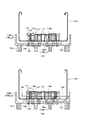
図6(A)及び図6(B)は、ベース筋116が配筋され、免震装置のフランジ形状に合わせて袋状ナット112が立設して設けられ、袋状ナット112に隣接して補強筋115aが配置された段階を示す。袋状ナット112の上面には定着板114が設けられている。袋状ナット112は、貫通孔104が形成されたベースプレート102の上面に配置されていてもよい。さらに、図6(A)及び図6(B)は、ベース筋116、定着板114が設けられた袋状ナット112、補強筋115aを囲むように型枠138(外側型枠138a、内側型枠138b)が設置される段階を示す。なお、図6(A)はこの段階での平面図を示し、図6(B)はこの段階での断面模式図を示す。図6(B)に示す構造のほか、図27に示すように、ベースプレート102を、底面を有する外側型枠138d上に設置し、ベースプレート102の周辺に木材などの間隙充填材141を敷設し、ベースプレート102及び外側型枠138dにはボルトが挿通される貫通口139を有する構造であってもよい。底面を有する外側型枠138dを用いることで、ベースプレート102をより安定的に支持することができる。また、外側型枠138dとベースプレート102との間に間隙充填材141を配置することで、ベースブレート102の位置がずれないようにすることができる。 6(A) and 6(B), the base reinforcement 116 is arranged, the bag-shaped nut 112 is provided upright according to the flange shape of the seismic isolation device, and is adjacent to the bag-shaped nut 112. The stage in which the reinforcing bars 115a are arranged is shown. A fixing plate 114 is provided on the upper surface of the bag-shaped nut 112 . The bag-shaped nut 112 may be arranged on the upper surface of the base plate 102 in which the through hole 104 is formed. 6(A) and 6(B) show a frame 138 (outer frame 138a, inner frame 138a) surrounding the base bar 116, the bag-shaped nut 112 provided with the fixing plate 114, and the reinforcing bar 115a. 138b) is installed. Note that FIG. 6A shows a plan view at this stage, and FIG. 6B shows a schematic cross-sectional view at this stage. Besides the structure shown in FIG. 6(B), as shown in FIG. The base plate 102 and the outer formwork 138d may have through holes 139 through which bolts are inserted. By using the outer formwork 138d having a bottom surface, the base plate 102 can be supported more stably. Further, by arranging the gap filler 141 between the outer mold frame 138d and the base plate 102, the position of the base plate 102 can be prevented from shifting.

ベースプレート102は、土台136の上に支持されていてもよい。袋状ナット112は、貫通孔104の位置に合わせて配置する。袋状ナット112は、ベースプレート102の下面から貫通孔104に挿通される取り付け用のボルトによって仮止めされてもよいし、図2(B)に示すように、溶接によってベースプレート102に固定されてもよい。 Base plate 102 may be supported on base 136 . The bag-like nut 112 is arranged in alignment with the position of the through hole 104 . The bag-shaped nut 112 may be temporarily fixed by a mounting bolt inserted through the through hole 104 from the bottom surface of the base plate 102, or may be fixed to the base plate 102 by welding as shown in FIG. 2(B). good.

定着板114が付けられた袋状ナット112が配置されたベースプレート102上に、ベース筋116が適宜配筋される。ベース筋116は、例えば、図示するように格子状に配筋する。ベース筋116は、フーチング籠筋118に相当する部分が上方に伸びるように配筋される。さらに、袋状ナット112と隣接するように補強筋115aを配筋し、補強筋固定筋117を連通させて固定する。 A base reinforcement 116 is appropriately arranged on the base plate 102 on which the bag-shaped nut 112 with the fixing plate 114 is arranged. The base reinforcements 116 are arranged in a grid pattern, for example, as illustrated. The base reinforcement 116 is arranged so that the part corresponding to the footing basket reinforcement 118 extends upward. Furthermore, the reinforcing bar 115a is arranged so as to be adjacent to the bag-like nut 112, and the reinforcing bar fixing bar 117 is connected and fixed.

ベースプレート102を囲む外側型枠138aと、外側型枠138aの内側に所定の間隔をもって内側型枠138bとが配置される。外側型枠138aは、ベースプレート102の上面部と高さが略一致する下部型枠部分を含んでいてもよい。内側型枠138bは立ち上がり部110を形成するために、ベースプレート102から浮いた状態で支持される。内側型枠138bの下端の高さは、袋状ナット112、定着板114、補強筋115a、及び補強筋固定筋117の高さより低くなるように配置される。外側型枠138aは土台136によって支持され、内側型枠138bは内側型枠固定用締結具140によって支持される。なお、外側型枠138aは、図示されない型枠用サポートによって配置が安定するように支持されていてもよい。外側型枠138a及び内側型枠138bは金属製又は木製であり、内側型枠固定用締結具140としては、例えば、ボルト及びナットが用いられる。 An outer mold frame 138a surrounding the base plate 102 and an inner mold frame 138b are arranged inside the outer mold frame 138a with a predetermined gap therebetween. The outer mold 138a may include a lower mold portion that is substantially flush with the upper surface of the base plate 102. As shown in FIG. The inner formwork 138b is supported in a floating state from the base plate 102 in order to form the raised portion 110. As shown in FIG. The height of the lower end of the inner formwork 138b is arranged so as to be lower than the heights of the bag-like nut 112, the fixing plate 114, the reinforcing bar 115a, and the reinforcing bar fixing bar 117. The outer mold 138a is supported by the base 136 and the inner mold 138b is supported by the inner mold fixing fasteners 140. As shown in FIG. The outer formwork 138a may be supported by a formwork support (not shown) so that its arrangement is stable. The outer formwork 138a and the inner formwork 138b are made of metal or wood, and bolts and nuts, for example, are used as fasteners 140 for fixing the inner formwork.

なお、袋状ナット112、ベース筋116の配筋、補強筋115aの配筋、外側型枠138a及び内側型枠138bを配置する手順は上記に限定されず適宜変更されてもよい。コンクリートを打設する前段階で図6(A)及び図6(B)に示す構造が出来上がっていれば、各部材を設置する順番は変更されてもよい。 The procedure for arranging the bag-shaped nut 112, the base reinforcement 116, the reinforcing reinforcement 115a, and the outer mold frame 138a and the inner mold frame 138b is not limited to the above and may be changed as appropriate. If the structure shown in FIGS. 6(A) and 6(B) has been completed before placing the concrete, the order of installing each member may be changed.

図7(A)は、内側型枠138bの下端又はその近傍までコンクリートを打設して平板部108を形成する段階を示す。コンクリートは、ベース筋116、袋状ナット112の下側部分、補強筋115aの下側部分を埋設し、袋状ナット112の上側部分、定着板114、補強筋115aの上側部分、補強筋固定筋117が露出するように打設される。この段階で打設されたコンクリートが硬化することにより、ベースプレート102上で、ベース筋116、袋状ナット112、補強筋115aが固定される。 FIG. 7(A) shows the stage of forming the flat plate portion 108 by pouring concrete up to or near the lower end of the inner formwork 138b. Concrete embeds the base bar 116, the lower part of the bag-like nut 112, the lower part of the reinforcing bar 115a, and the upper part of the bag-like nut 112, the fixing plate 114, the upper part of the reinforcing bar 115a, and the reinforcing bar fixing bar. It is driven so that 117 is exposed. By hardening the cast concrete at this stage, the base reinforcement 116 , the bag-shaped nut 112 and the reinforcing reinforcement 115 a are fixed on the base plate 102 .

図7(B)は、外側型枠138aと内側型枠138bとの間にコンクリートを打設する段階を示す。外側型枠138aと内側型枠138bとの間にコンクリートを流し込む作業は、平板部108を形成するコンクリートが安定化し、ある程度硬化した状態で行われることが好ましい。外側型枠138aと内側型枠138bとの間に打設されたコンクリートにより、立ち上がり部110が形成される。立ち上がり部110の高さは、外側型枠138aと内側型枠138bとの間に流し込むコンクリートの量によって調整することができる。この場合において、外側型枠138aと内側型枠138bとの間に流し込まれるコンクリートの量は、少なくとも平板部108から突出する定着板114、補強筋115aの上端部、及び補強筋固定筋117の高さより高くなるのに十分な量であることが望ましい。 FIG. 7(B) shows the step of placing concrete between the outer formwork 138a and the inner formwork 138b. The work of pouring concrete between the outer mold frame 138a and the inner mold frame 138b is preferably performed after the concrete forming the flat plate portion 108 is stabilized and hardened to some extent. The raised portion 110 is formed by concrete placed between the outer mold frame 138a and the inner mold frame 138b. The height of the rising portion 110 can be adjusted by adjusting the amount of concrete poured between the outer formwork 138a and the inner formwork 138b. In this case, the amount of concrete poured between the outer formwork 138a and the inner formwork 138b is at least the height of the fixing plate 114 projecting from the flat plate portion 108, the upper end of the reinforcing bar 115a, and the height of the reinforcing bar fixing bar 117. It is desirable to have an amount sufficient to be higher than the height.

コンクリートが硬化した後、外側型枠138a及び内側型枠138bが除去される。このようなプレキャストコンクリート(PCa)工法によって、図1(A)及び図1(B)に示すような免震上部基礎構造100aが作製される。本実施形態で示すように、プレキャストコンクリートを2段階に分けて打設することにより、立ち上がり部110を有すると共に、袋状ナット112の上側部分、定着板114、補強筋115aの上側部分、補強筋固定筋117が露出する免震上部基礎構造100aを作製することができる。なお、本実施形態では、図7(A)及び図7(B)に示すように、コンクリートを2段階で打設する態様を示すが、これに限定されず、コンクリートの1回の打設により平板部108と立ち上がり部110を形成してもよい。 After the concrete has set, the outer formwork 138a and the inner formwork 138b are removed. A seismic isolation upper foundation structure 100a as shown in FIGS. 1(A) and 1(B) is produced by such a precast concrete (PCa) construction method. As shown in this embodiment, precast concrete is placed in two stages to provide the rising portion 110, the upper portion of the bag-shaped nut 112, the fixing plate 114, the upper portion of the reinforcing bar 115a, and the reinforcing bar. A seismic isolation upper foundation structure 100a in which the fixing muscles 117 are exposed can be produced. In this embodiment, as shown in FIGS. 7(A) and 7(B), concrete is placed in two steps. However, the present invention is not limited to this. A flat plate portion 108 and a raised portion 110 may be formed.

本実施形態に係る作製方法によれば、免震上部基礎構造を作製するために作業現場でコンクリートを打設する必要がないので、型枠及び型枠用サポートの設置作業をする必要がなく、煩雑な作業を削減することができる。また、免震上部基礎構造用の鉄筋と、基礎梁用の鉄筋とが混在することを防ぐことができるので、配筋の作業を簡略化することができる。 According to the manufacturing method according to the present embodiment, since it is not necessary to cast concrete at the work site in order to manufacture the seismic isolation upper foundation structure, there is no need to install the formwork and the support for the formwork. Complicated work can be reduced. In addition, since it is possible to prevent the reinforcing bars for the seismic isolation upper foundation structure from being mixed with the reinforcing bars for the foundation beams, it is possible to simplify the work of arranging the reinforcing bars.

さらに、本実施形態に係る免震上部基礎構造は、免震装置の直上で作製するのではなく、工場や作業所内で個別に生産することができるため、コンクリートの品質管理が容易であり、品質のばらつきを小さくすることができるという利点を有する。また、免震上部基礎構造100aを工場で作製する場合は、天候等の影響を受けず計画的に生産することができるため、工期を短縮することができる。さらに、現場でコンクリートを打設する工法に比べ、型枠及び型枠サポートの使用量を削減することができ、現場において煩雑な作業を省略することができ、建設コストを削減することができる。 Furthermore, the seismic isolation upper foundation structure according to the present embodiment is not manufactured directly above the seismic isolation device, but can be produced individually in a factory or work place. has the advantage of being able to reduce the variation of In addition, when the seismic isolation upper foundation structure 100a is manufactured in a factory, it can be produced systematically without being affected by the weather and the like, so that the construction period can be shortened. Furthermore, compared to the method of placing concrete on site, the amount of formwork and formwork support used can be reduced, cumbersome work can be omitted at the site, and construction costs can be reduced.

(3)フーチング構造体
図8は、本発明の一実施形態に係るフーチング構造体200を示す。フーチング構造体200は、免震上部基礎構造100aと、その上に設けられた鉄筋コンクリート製のフーチング131を含む。図8は、フーチング構造体200が免震装置122の上に設置された状態を示す断面図である。
(3) Footing Structure FIG. 8 shows a footing structure 200 according to one embodiment of the present invention. The footing structure 200 includes a seismic isolation upper foundation structure 100a and a reinforced concrete footing 131 provided thereon. FIG. 8 is a cross-sectional view showing a state in which the footing structure 200 is installed on the seismic isolation device 122. As shown in FIG.

免震上部基礎構造100aは、アンカーボルト130によって免震装置122に固定される。免震装置122は、免震ゴム部124と上部フランジ126及び下部フランジ128を含む。アンカーボルト130は、免震装置122の上部フランジ126からベースプレート102の貫通孔104に挿通され、袋状ナット112に螺合される。免震上部基礎構造100aは、アンカーボルト130によって複数箇所が締結されることで、免震装置122の上に安定的に保持される。なお、免震装置122は、免震下部基礎構造120の上に、下部フランジ128を挿通するアンカーボルト130によって固定される。 The seismic isolation upper foundation structure 100 a is fixed to the seismic isolation device 122 by anchor bolts 130 . The seismic isolation device 122 includes a seismic isolation rubber portion 124 , an upper flange 126 and a lower flange 128 . Anchor bolts 130 are inserted from the upper flange 126 of the seismic isolation device 122 through the through holes 104 of the base plate 102 and screwed into the bag-shaped nuts 112 . The seismic isolation upper foundation structure 100 a is stably held on the seismic isolation device 122 by being fastened at multiple locations with anchor bolts 130 . The seismic isolation device 122 is fixed on the seismic isolation lower foundation structure 120 by anchor bolts 130 that pass through the lower flanges 128 .

免震上部基礎構造100aの上にはフーチング131及び基礎梁132が設けられる。フーチング131及び基礎梁132は、梁主筋(図8では図示せず)を埋設するようにコンクリートを打設することで作製される。フーチング131及び基礎梁132を形成するコンクリートは、免震上部基礎構造100aの上面部と密接するように設けられる。すなわち、フーチング131及び基礎梁132を形成するコンクリートは、免震上部基礎構造100aの立ち上がり部110及び平板部108の上面と密接するように設けられる。これにより、コンクリート部106の平板部108と立ち上がり部110とで形成される凹状の領域に、フーチング131及び基礎梁132を形成するコンクリートが充填される。立ち上がり部110から突出するフーチング籠筋118は、フーチング131の中に伸びることで、免震上部基礎構造100aとフーチング131及び基礎梁132との接合強度を高めている。 A footing 131 and a foundation beam 132 are provided on the seismic isolation upper foundation structure 100a. The footing 131 and the foundation beam 132 are produced by placing concrete so as to bury the beam main reinforcement (not shown in FIG. 8). Concrete forming the footing 131 and the foundation beam 132 is provided so as to be in close contact with the upper surface of the seismic isolation upper foundation structure 100a. That is, the concrete forming the footing 131 and the foundation beam 132 is provided so as to be in close contact with the rising portion 110 and the upper surface of the flat plate portion 108 of the seismic isolation upper foundation structure 100a. As a result, the concrete forming the footing 131 and the foundation beam 132 is filled in the concave region formed by the flat plate portion 108 and the rising portion 110 of the concrete portion 106 . The footing cage reinforcement 118 protruding from the rising portion 110 extends into the footing 131 to increase the joint strength between the seismic isolation upper foundation structure 100a, the footing 131 and the foundation beams 132 .

免震上部基礎構造100a及び基礎梁132はコンクリートで形成される。さらに、フーチング籠筋118がフーチング131へ突出するように設けられる。免震上部基礎構造100aの立ち上がり部110は、基礎梁132に横方向の力が作用したとき反作用を生じる部位となり、基礎梁132の横方向の滑りに対して抵抗を生じさせる。これにより、免震上部基礎構造100aは、地震の横揺れに対する建造物の耐性を高めることができる。 The seismic isolation upper foundation structure 100a and foundation beams 132 are made of concrete. Furthermore, the footing cage reinforcement 118 is provided so as to protrude to the footing 131 . The rising portion 110 of the seismic isolation upper foundation structure 100a is a portion that produces a reaction when a lateral force acts on the foundation beam 132, and produces resistance against lateral sliding of the foundation beam 132. FIG. As a result, the seismic isolation upper foundation structure 100a can enhance the resistance of the building to the rolling of an earthquake.

免震上部基礎構造100aにおいて、平板部108から突出する袋状ナット112及び定着板114は、フーチング131の中に埋設される。定着板114は袋状ナット112の本体から突出するように設けられているので、フーチング131及び基礎梁132に作用する縦方向の力に対して抵抗力を生じさせる部位となる。 In the seismic isolation upper foundation structure 100 a , the bag-shaped nut 112 and the fixing plate 114 projecting from the flat plate portion 108 are embedded in the footing 131 . Since the fixing plate 114 is provided so as to protrude from the main body of the bag-like nut 112 , it is a portion that produces a resistance force against vertical force acting on the footing 131 and the foundation beam 132 .

補強筋115aは、図4を参照して説明したように、フーチング131に想定されるコーン状破壊面DFを交差するように配置される。補強筋115aは、コーン状破壊面DFと交差するように配置されることで、コンクリートの脆性を改善し、コーン状破壊に対する耐性が向上するように作用する。 The reinforcing bars 115a are arranged so as to intersect the cone-shaped failure plane DF assumed in the footing 131, as described with reference to FIG. The reinforcing bars 115a are arranged so as to intersect the cone-shaped fracture surface DF, thereby improving the brittleness of concrete and improving the resistance to cone-shaped fracture.

本実施形態に係るフーチング構造体200によれば、補強筋115aがフーチング131に生じ得るコーン状破壊面DFと交差するように設けられることで、アンカーに引張応力が作用した際のコーン状破壊耐性を高めることができる。それにより、免震基礎構造の耐震性を高めることができる。 According to the footing structure 200 according to the present embodiment, the reinforcing bars 115a are provided so as to intersect with the cone-shaped fracture surface DF that can occur in the footing 131, so that the cone-shaped fracture resistance when tensile stress acts on the anchor is increased. can increase As a result, the seismic resistance of the seismic isolation foundation structure can be enhanced.

(4)免震基礎の施工方法
図9乃至図13を参照して、本発明の一実施形態に係る免震上部基礎構造100aを用いた免震基礎の施工方法について説明する。
(4) Construction Method for Base Isolation Foundation A construction method for base isolation foundation using the base isolation upper foundation structure 100a according to one embodiment of the present invention will be described with reference to FIGS. 9 to 13 .

プレキャストコンクリート(PCa)工法で作製された免震上部基礎構造100aは、基礎工事が行われる建設現場の設置場所に搬送される。図9に示すように、免震装置122は、免震下部基礎構造120の上に設置された状態にある。免震上部基礎構造100aは、免震装置122の上部フランジ126の上に設置され、アンカーボルト130によって固定される。 The seismic isolation upper foundation structure 100a manufactured by the precast concrete (PCa) construction method is transported to an installation site at a construction site where foundation work is performed. As shown in FIG. 9 , the seismic isolation device 122 is installed on the seismic isolation lower foundation structure 120 . The seismic isolation upper foundation structure 100 a is installed on the upper flange 126 of the seismic isolation device 122 and fixed by anchor bolts 130 .

その後、図10に示すように、免震上部基礎構造100aの上に、基礎梁を形成するための梁主筋等を配筋する作業が行われる。梁主筋134a、134bは、それぞれ基礎梁の長手方向に配筋される。このとき、免震上部基礎構造100aの立ち上がり部110は、梁主筋134bを支持する部位として利用される。さらに梁主筋134a、134bの周囲には、せん断補強筋(フープ筋ともいう)142が適宜配筋される。梁主筋134a、134bとせん断補強筋142とは結束線で適宜結束される。 After that, as shown in FIG. 10, on the seismic isolation upper foundation structure 100a, the work of arranging beam main reinforcements and the like for forming foundation beams is performed. The beam main reinforcements 134a and 134b are respectively arranged in the longitudinal direction of the foundation beam. At this time, the rising portion 110 of the seismic isolation upper foundation structure 100a is used as a portion for supporting the beam main reinforcement 134b. Further, shear reinforcing bars (also called hoop bars) 142 are appropriately arranged around the beam main bars 134a and 134b. The beam main reinforcements 134a and 134b and the shear reinforcing reinforcements 142 are appropriately bound with binding lines.

図11は、コンクリートを打設してフーチング131及び基礎梁132を作製する段階を示す。梁主筋134a、134bはスペーサ143によって免震上部基礎構造100aの立ち上がり部110の上面から浮いた状態で支持される。梁主筋134a、134b及びせん断補強筋142を囲むように、図示されない型枠及び型枠用サポートを設置し、コンクリートを打設する。コンクリートは、免震上部基礎構造100aの上面側にも打設される。コンクリートは、免震上部基礎構造100aの立ち上がり部110と平板部108とで形成される凹状の領域にも充填される。その結果、袋状ナット112の上側部分、定着板114、補強筋115aの上側部分、及び補強筋固定筋117がコンクリートに埋設される。また、基礎梁132と免震上部基礎構造100aが交差する部分では、立ち上がり部110が基礎梁132のコンクリートの下端に位置するように形成される。基礎梁用のコンクリートを養生させた後、図示されない型枠を除去することで、フーチング構造体200及び基礎梁132が形成される。なお、補強筋115a、袋ナット112及び定着板114と、せん断補強筋142及び梁主筋134a、134bとの間には、30mm以上の間隙を設けることが好ましい。 FIG. 11 shows the stage of pouring concrete to produce footings 131 and foundation beams 132 . The beam main reinforcements 134a and 134b are supported by spacers 143 in a state of floating from the upper surface of the rising portion 110 of the seismic isolation upper foundation structure 100a. A formwork and formwork support (not shown) are installed so as to surround the beam main reinforcements 134a and 134b and the shear reinforcement 142, and concrete is placed. Concrete is also placed on the upper surface side of the seismic isolation upper foundation structure 100a. Concrete is also filled in the recessed region formed by the rising portion 110 and the flat plate portion 108 of the seismic isolation upper foundation structure 100a. As a result, the upper portion of the bag-like nut 112, the fixing plate 114, the upper portion of the reinforcing bar 115a, and the reinforcing bar fixing bar 117 are embedded in the concrete. Also, in the portion where the base beam 132 and the seismic isolation upper foundation structure 100a intersect, the rising portion 110 is formed so as to be positioned at the lower end of the concrete of the base beam 132 . After curing the concrete for the foundation beams, the footing structure 200 and the foundation beams 132 are formed by removing the formwork (not shown). It is preferable to provide a gap of 30 mm or more between the reinforcing bar 115a, the cap nut 112, the fixing plate 114, and the shear reinforcing bar 142 and the beam main bars 134a, 134b.

図13(A)は、免震上部基礎構造100aが免震装置122に取り付けられ、フーチング131及び鉄筋コンクリートで形成された基礎梁132が形成された状態を斜視図で示す。免震装置122の上に形成されたフーチング構造体200は、隣接するフーチング構造体同士を連結するように基礎梁132が水平方向に延設される。なお図13(A)では図示されないが、フーチング131の上には柱脚が垂直方向に設けられる。 FIG. 13(A) is a perspective view showing a state in which the seismic isolation upper foundation structure 100a is attached to the seismic isolation device 122, and footings 131 and foundation beams 132 made of reinforced concrete are formed. The footing structure 200 formed on the seismic isolation device 122 has foundation beams 132 extending horizontally so as to connect adjacent footing structures. Although not shown in FIG. 13A, column bases are vertically provided on the footing 131 .

図12は、基礎梁132が鉄骨材で形成された態様を示す断面図である。基礎梁132に用いることのできる鉄骨材としては各種の形鋼を用いることができる。図12は基礎梁132にH形鋼が用いられた態様を示す。この場合、免震上部基礎構造100aの立ち上がり部110の上面に基礎梁132として用いられる鉄骨材が直接配設される。免震上部基礎構造100aは、立ち上がり部110を有することにより、袋状ナット112、定着板114、補強筋115a、及び補強筋固定筋117と干渉しないように配置することができる。免震上部基礎構造100aの上にはコンクリートが打設され、フーチング131が形成される。なお、補強筋115a、袋ナット112及び定着板114と、鉄骨梁下端との間には、30mm以上の間隙を設けることが好ましい。 FIG. 12 is a cross-sectional view showing a mode in which the foundation beam 132 is made of steel. Various shaped steels can be used as steel frames that can be used for the foundation beams 132 . FIG. 12 shows a mode in which H-section steel is used for the foundation beam 132. FIG. In this case, the steel frame material used as the foundation beam 132 is directly arranged on the upper surface of the rising portion 110 of the seismic isolation upper foundation structure 100a. Since the seismic isolation upper foundation structure 100a has the rising portion 110, it can be arranged so as not to interfere with the bag-shaped nut 112, the fixing plate 114, the reinforcing bar 115a, and the reinforcing bar fixing bar 117. Concrete is placed on the seismic isolation upper foundation structure 100a to form a footing 131 . In addition, it is preferable to provide a gap of 30 mm or more between the reinforcing bar 115a, the cap nut 112, the fixing plate 114, and the lower end of the steel frame beam.

図13(B)は、免震上部基礎構造100aが免震装置122に取り付けられ、さらにフーチング131及び鉄骨材で形成された基礎梁132が形成された状態を示す斜視図である。免震装置122の上に形成されたフーチング構造体200は、隣接するフーチング構造体同士を連結するように基礎梁132が水平方向に延設される。なお図14(B)では図示されないが、フーチング131の上には柱脚が垂直方向に設けられる。 FIG. 13B is a perspective view showing a state in which the seismic isolation upper foundation structure 100a is attached to the seismic isolation device 122, and footings 131 and foundation beams 132 made of steel frames are formed. The footing structure 200 formed on the seismic isolation device 122 has foundation beams 132 extending horizontally so as to connect adjacent footing structures. Although not shown in FIG. 14B, column bases are vertically provided on the footing 131 .

本実施形態に係る免震基礎の施工方法によれば、プレキャストコンクリート(PCa)で作製された免震上部基礎構造100aの上にフーチング131及び基礎梁132を密接して形成することが可能となる。また、平板部108から露出する袋状ナット112及び定着板114は、フーチング131のコンクリートに埋設されることで、縦方向の振動に対して高い耐性を発揮することができる。さらに、フーチング構造体200は、コーン状破壊面と交差するように補強筋115aが配筋されていることにより、コーン状破壊耐性を高めることができる。別言すれば、免震装置122とフーチング構造体200を連結するアンカー(アンカーボルト及び袋状ナット112)に作用する縦方向の引張応力に対して耐性を高めることができる。このように、本実施形態に係る免震基礎の施工方法によれば、耐震性の高い基礎構造を形成することができる。 According to the seismic isolation foundation construction method according to the present embodiment, it is possible to closely form the footing 131 and the foundation beams 132 on the seismic isolation upper foundation structure 100a made of precast concrete (PCa). . Further, the bag-like nut 112 and the fixing plate 114 exposed from the flat plate portion 108 are embedded in the concrete of the footing 131, thereby exhibiting high resistance to vibration in the vertical direction. Furthermore, the footing structure 200 can enhance resistance to cone-shaped failure by arranging reinforcing bars 115a so as to intersect the cone-shaped failure surface. In other words, it is possible to increase the resistance to vertical tensile stress acting on the anchors (anchor bolts and cap-like nuts 112) connecting the seismic isolation device 122 and the footing structure 200. FIG. Thus, according to the construction method of the seismic isolation foundation according to the present embodiment, a foundation structure with high earthquake resistance can be formed.

なお、本実施形態は、免震上部基礎構造100aを、プレキャストコンクリート(PCa)工法で作製する一例を示すが、本発明はこれに限定して解釈されるものではない。 In addition, although this embodiment shows an example which produces the seismic isolation upper foundation structure 100a by a precast concrete (PCa) construction method, this invention is not limited to this and is interpreted.

第2の実施形態:
本実施形態は、第1の実施形態における免震上部基礎構造100aと比較して、補強筋の構成が異なる一例を示す。図14(A)は、本実施形態に係る免震上部基礎構造100bの平面図を示し、図14(B)は断面構造の模式図を示す。以下の説明においては、第1の実施形態と相違する部分を中心に説明する。
Second embodiment:
This embodiment shows an example in which the configuration of reinforcing bars is different from that of the seismic isolation upper foundation structure 100a in the first embodiment. FIG. 14(A) shows a plan view of a seismic isolation upper foundation structure 100b according to this embodiment, and FIG. 14(B) shows a schematic diagram of a cross-sectional structure. In the following description, the differences from the first embodiment will be mainly described.

図14(A)及び図14(B)に示すように免震上部基礎構造100bは、ベースプレート102、ベース筋116、コンクリート部106、袋状ナット112、袋状ナット112の上部に付された定着板114、補強筋115b、及び環状筋119(第1環状筋119aと第2環状筋119b)を含んで構成される。ベースプレート102、ベース筋116、コンクリート部106、袋状ナット112、及び定着板114の構成は第1の実施形態におけるものと同様である。 As shown in FIGS. 14A and 14B, the seismic isolation upper foundation structure 100b includes a base plate 102, a base reinforcement 116, a concrete portion 106, a bag-like nut 112, and fixings attached to the upper part of the bag-like nut 112. It includes a plate 114, a reinforcement 115b, and a circular muscle 119 (a first circular muscle 119a and a second circular muscle 119b). The configurations of the base plate 102, the base reinforcement 116, the concrete portion 106, the bag-shaped nut 112, and the fixing plate 114 are the same as those in the first embodiment.

図14(A)に示すように、環状筋119は、ベースプレート102の中心を円心として所定の半径を有する円周上に配置された複数の袋状ナット112の外側を囲むように設けられる第1環状筋119aと、内側を囲むように設けられる第2環状筋119bとを有する。なお、環状筋とは、環状をなす鉄筋をいうものとする。環状筋は、円形又は複数の屈曲部を有する多角形状を有する。図14(A)は、第1環状筋119a及び第2環状筋119bが、平面視において八角形状を有する態様を示す。 As shown in FIG. 14(A), the annular muscle 119 is provided so as to surround the outer sides of a plurality of cap-like nuts 112 arranged on a circle having a predetermined radius with the center of the base plate 102 as the center of the circle. It has a first circular muscle 119a and a second circular muscle 119b surrounding the inside. It should be noted that the ring-shaped reinforcing bar means a ring-shaped reinforcing bar. The circular muscle has a circular or polygonal shape with multiple bends. FIG. 14A shows a mode in which the first circular muscle 119a and the second circular muscle 119b have an octagonal shape in plan view.

図14(B)に示すように、第1環状筋119a及び第2環状筋119bは、コンクリート部106における平板部108の面上であって、袋状ナット112及び定着板114の高さより高い位置に配置される。また、第1環状筋119a及び第2環状筋119bは、コンクリート部106において立ち上がり部110の高さより低い位置に配置される。第1環状筋119a及び第2環状筋119bは、このような高さに配置されることで、第1の実施形態と同様に、梁主筋を配筋するときに環状筋が干渉しないようにすることができる。 As shown in FIG. 14B, the first circular muscle 119a and the second circular muscle 119b are positioned above the plane of the flat plate portion 108 in the concrete portion 106 and above the height of the bag-like nut 112 and the fixing plate 114. placed in Also, the first circular muscle 119 a and the second circular muscle 119 b are arranged at a position lower than the height of the rising portion 110 in the concrete portion 106 . By arranging the first circular muscle 119a and the second circular muscle 119b at such heights, as in the first embodiment, the circular muscles do not interfere when the beam main reinforcement is arranged. be able to.

補強筋115bは、線状の鉄筋の両端が開放端となるように屈曲された、U字型(又はコの字型)の構造を有する。図5(B)は、このようなU字型の補強筋115bの一例を示す。補強筋115bは、U字型の本体部と、U字型の先端から曲げられた折り曲げ部とを含む。図14(B)に示すように、補強筋115bは、U字型の本体部が第1環状筋119aと第2環状筋119bとに掛けられ、折り曲げ部がベース筋116に掛け渡される。補強筋115bは、環状筋119(第1環状筋19a、第2環状筋119b)とベース筋116とに掛け渡されることで、袋状ナット112に隣接して立設するように配置される。補強筋115bは、環状筋119(第1環状筋19a、第2環状筋119b)及びベース筋116と、結束線で結束されている。 The reinforcing bar 115b has a U-shaped (or U-shaped) structure in which both ends of a linear reinforcing bar are bent to be open ends. FIG. 5B shows an example of such a U-shaped reinforcing bar 115b. The reinforcing bar 115b includes a U-shaped main body portion and a bent portion bent from the U-shaped tip. As shown in FIG. 14(B), the reinforcing bar 115b has a U-shaped main body portion that is hooked to the first circular bar 119a and the second circular bar 119b, and a bent portion that spans the base bar 116. As shown in FIG. The reinforcing bar 115b is arranged to stand adjacent to the bag-shaped nut 112 by being spanned between the circular bar 119 (the first circular bar 19a and the second circular bar 119b) and the base bar 116 . The reinforcing muscle 115b is bound with the circular muscle 119 (the first circular muscle 19a and the second circular muscle 119b) and the base muscle 116 with binding lines.

図14(A)に示すように、補強筋115bは、袋状ナット112に対し、少なくとも一つが隣接するように配置される。コンクリート部106において、補強筋115bは複数個配置される。複数個の補強筋115bは、環状筋119(第1環状筋19a、第2環状筋19b)が連通されることで相互に支え合い、せん断力に対する耐性が高められる。また、補強筋115bは、第1の実施形態と同様に、フーチングのコーン状破壊面を交差するように配置される。それにより、アンカーに引張応力が作用した際のコーン状破壊耐性を高めることができ、免震基礎構造の耐震性を高めることができる。 As shown in FIG. 14A, the reinforcing bars 115b are arranged so that at least one of the reinforcing bars 115b is adjacent to the cap-shaped nut 112. As shown in FIG. In the concrete portion 106, a plurality of reinforcing bars 115b are arranged. The plurality of reinforcing muscles 115b support each other by connecting the circular muscles 119 (the first circular muscle 19a and the second circular muscle 19b), thereby increasing the resistance to shearing force. Further, the reinforcing bars 115b are arranged so as to intersect the cone-shaped fracture surface of the footing, as in the first embodiment. As a result, the cone-shaped fracture resistance when the tensile stress acts on the anchor can be enhanced, and the seismic resistance of the seismic isolation foundation structure can be enhanced.

本実施形態に係る免震上部基礎構造100bは、第1実施形態で説明される製造方法と同様の方法で作製することができる。また、第1の実施形態と同様に、免震上部基礎構造100bの上にフーチングを形成することでフーチング構造体を形成することができる。本実施形態に係る免震上部基礎構造100bを用いたフーチング構造体も、第1の実施形態と同様の作用効果を得ることができる。さらに、本実施形態に係る免震上部基礎構造100bを用いて免震基礎を施工することができる。 The seismic isolation upper foundation structure 100b according to this embodiment can be manufactured by the same method as the manufacturing method described in the first embodiment. Further, similarly to the first embodiment, a footing structure can be formed by forming a footing on the seismic isolation upper foundation structure 100b. The footing structure using the seismic isolation upper foundation structure 100b according to this embodiment can also obtain the same effects as those of the first embodiment. Furthermore, a seismic isolation foundation can be constructed using the seismic isolation upper foundation structure 100b according to the present embodiment.

第3の実施形態:
本実施形態は、第1の実施形態における免震上部基礎構造100aと比較して、補強筋の構成が異なる一例を示す。図15(A)は、本実施形態に係る免震上部基礎構造100cの平面図を示し、図15(B)は断面構造の模式図を示す。以下の説明においては、第1の実施形態と相違する部分を中心に説明する。
Third embodiment:
This embodiment shows an example in which the configuration of reinforcing bars is different from that of the seismic isolation upper foundation structure 100a in the first embodiment. FIG. 15(A) shows a plan view of the seismic isolation upper foundation structure 100c according to this embodiment, and FIG. 15(B) shows a schematic diagram of the cross-sectional structure. In the following description, the differences from the first embodiment will be mainly described.

図15(A)及び図15(B)に示すように免震上部基礎構造100cは、ベースプレート102、ベース筋116、コンクリート部106、袋状ナット112、袋状ナット112の上部に付された定着板114、補強筋115cを含んで構成される。ベースプレート102、ベース筋116、コンクリート部106、袋状ナット112、定着板114、及び補強筋固定筋117の構成は第1の実施形態におけるものと同様である。 As shown in FIGS. 15A and 15B, the seismic isolation upper foundation structure 100c includes a base plate 102, a base reinforcement 116, a concrete portion 106, a bag-like nut 112, and fixings attached to the upper part of the bag-like nut 112. It is configured including a plate 114 and reinforcing bars 115c. The configurations of the base plate 102, the base reinforcement 116, the concrete portion 106, the bag-shaped nut 112, the fixing plate 114, and the reinforcing reinforcement reinforcement 117 are the same as those in the first embodiment.

本実施形態に係る補強筋115cは、線状の鉄筋が少なくとも4箇所で屈曲された鉤型の形状を有する。図5(C)は、このような鉤型の補強筋115cの一例を示す。補強筋115cは、線状の鉄筋の両端から内側に一定の長さで伸びる第1直線部分15aと、一方向に屈曲され直線状に延びる第2直線部分15bと、第2直線部分15bの一端が屈曲されて形成される第3直線部分15cを含む。別言すれば、補強筋115cは、コの字型に屈曲した鉄筋の先端部分が、さらに外側に曲げられた形状とみなすこともできる。 The reinforcing bar 115c according to this embodiment has a hook shape in which a linear reinforcing bar is bent at at least four points. FIG. 5C shows an example of such a hook-shaped reinforcing bar 115c. The reinforcing bar 115c includes a first linear portion 15a extending inward from both ends of the linear reinforcing bar with a constant length, a second linear portion 15b bent in one direction and extending linearly, and one end of the second linear portion 15b. includes a third straight portion 15c formed by bending the . In other words, the reinforcing bar 115c can also be considered to have a shape in which the tip portion of the reinforcing bar bent in a U-shape is further bent outward.

図15(A)及び図15(B)は、補強筋115cが、袋状ナット112に隣接して配置される態様を示す。補強筋115cは袋状ナット112を挟むように配置される。すなわち、一つの袋状ナット112に対して少なくとも2つの補強筋115cが隣接するように配置される。補強筋115cの上部には、補強筋固定筋117が交差するように設けられる。図15(A)は、第1補強筋115c_1と第2補強筋115c_2とが間隙を持って略平行に配置され、両者の間(間隙部分)に袋状ナット112_1が配置される態様を示す。第1補強筋115c_1及び第2補強筋115c_2は、第2直線部分15bが袋状ナット112_1と略平行となるように立設して配置される。第1補強筋固定筋117_1及び第2補強筋固定筋117_2は、第1補強筋115c_1及び第2補強筋115c_2を挿通するように配置され、結束線で結束される。補強筋115cの高さは、定着板114の上に設置した補強筋固定筋117よりも高くすることが好ましい。それにより、定着板114及び袋状ナット112と干渉することなく、定着板114の上部で、補強筋115cと補強筋固定筋117とを結束することができる。補強筋115cは、図4を参照して説明したように、コーン状破壊面を交差するように配置されていることが好ましい。なお、図15(b)に示すように、コンクリート部106が立ち上がり部110を有する場合は、袋状ナット112、定着板114、及び補強筋115cの高さは、立ち上がり部110の高さより低いことが好ましい。 15(A) and 15(B) show a mode in which the reinforcement 115c is arranged adjacent to the cap-like nut 112. FIG. The reinforcing bars 115c are arranged so as to sandwich the bag-like nut 112. As shown in FIG. That is, at least two reinforcing bars 115c are arranged adjacent to one bag-like nut 112. As shown in FIG. Above the reinforcing bar 115c, the reinforcing bar fixing bar 117 is provided so as to intersect. FIG. 15(A) shows a mode in which the first reinforcing bar 115c_1 and the second reinforcing bar 115c_2 are arranged substantially parallel with a gap therebetween, and the bag-like nut 112_1 is arranged between them (gap portion). The first reinforcing bar 115c_1 and the second reinforcing bar 115c_2 are erected and arranged such that the second linear portion 15b is substantially parallel to the bag-like nut 112_1. The first reinforcing bar-fixing bar 117_1 and the second reinforcing bar-fixing bar 117_2 are arranged so as to pass through the first reinforcing bar 115c_1 and the second reinforcing bar 115c_2, and are bound with a binding wire. The reinforcing bar 115 c is preferably higher than the reinforcing bar fixing bar 117 installed on the fixing plate 114 . As a result, the reinforcing bar 115 c and the reinforcing bar fixing bar 117 can be bound above the fixing plate 114 without interfering with the fixing plate 114 and the bag-like nut 112 . The reinforcing bars 115c are preferably arranged to intersect the cone-shaped fracture surface, as described with reference to FIG. In addition, as shown in FIG. 15B, when the concrete portion 106 has a rising portion 110, the height of the bag-like nut 112, the fixing plate 114, and the reinforcing bars 115c must be lower than the height of the rising portion 110. is preferred.

補強筋115cは、結束線によりベース筋116に結束される。補強筋115cをベース筋116に結束するため、補強筋115cは第1直線部分15aがベース筋116と交差するように配置されることが好ましい。例えば、図15(A)に示すように、長手方向(第1直線部分15a、第3直線部分15c)がX方向と平行に配筋される第1補強筋115c_1及び第2補強筋115c_2は、第1直線部15aに相当する部分がY方向に伸びる第1ベース筋116_1及び第2ベース筋116_2と交差するように配置される。そして、第1補強筋115c_1及び第2補強筋115c_2は、第1ベース筋116_1及び第2ベース筋116_2と当該交差部でそれぞれ結束線により結束される。また、第1補強筋115c_1及び第2補強筋115c_2は、第1ベース筋116_1及び第2ベース筋116_2と略平行に配設された第1補強筋固定筋117_1及び第2補強筋固定筋117_2と結束線により結束される。一方、長手方向がY方向と平行な方向に配筋される第3補強筋115c_3及び第4補強筋115c_4は、第1直線部15aに相当する部分がX方向に伸びる第3ベース筋116_3及び第4ベース筋116_4と交差するように配置される。そして、第3補強筋115c_3及び第4補強筋115c_4は、第3ベース筋116_3及び第4ベース筋116_4と当該交差部でそれぞれ結束線により結束される。また、第3補強筋115c_3及び第4補強筋115c_4は、第3ベース筋116_3及び第4ベース筋116_4と略平行に配設された第3補強筋固定筋117_3及び第4補強筋固定筋117_4と結束線により結束される。 The reinforcing bar 115c is bound to the base bar 116 by a binding wire. In order to tie the reinforcing bar 115 c to the base bar 116 , the reinforcing bar 115 c is preferably arranged such that the first straight portion 15 a crosses the base bar 116 . For example, as shown in FIG. 15(A), a first reinforcing bar 115c_1 and a second reinforcing bar 115c_2 whose longitudinal directions (first straight portion 15a, third straight portion 15c) are arranged parallel to the X direction are A portion corresponding to the first linear portion 15a is arranged to intersect the first base bar 116_1 and the second base bar 116_2 extending in the Y direction. Then, the first reinforcing bar 115c_1 and the second reinforcing bar 115c_2 are bound with the first base bar 116_1 and the second base bar 116_2 at the intersections with binding lines, respectively. In addition, the first reinforcing bar 115c_1 and the second reinforcing bar 115c_2 are arranged with the first reinforcing bar fixing bar 117_1 and the second reinforcing bar fixing bar 117_2 which are arranged substantially parallel to the first base bar 116_1 and the second base bar 116_2. It is bound by a binding wire. On the other hand, the third reinforcing bar 115c_3 and the fourth reinforcing bar 115c_4 whose longitudinal direction is parallel to the Y direction are the third base bar 116_3 and the fourth reinforcing bar 116_3 whose portions corresponding to the first straight portions 15a extend in the X direction. It is arranged so as to intersect with the 4 base muscle 116_4. Then, the third reinforcing bar 115c_3 and the fourth reinforcing bar 115c_4 are bound with the third base bar 116_3 and the fourth base bar 116_4 at the intersections with binding lines, respectively. In addition, the third reinforcing bar 115c_3 and the fourth reinforcing bar 115c_4 are connected with the third reinforcing bar fixing bar 117_3 and the fourth reinforcing bar fixing bar 117_4 which are arranged substantially parallel to the third base bar 116_3 and the fourth base bar 116_4. It is bound by a binding wire.

図16は、第1補強筋115c_1及び第2補強筋115c_2(図示されず)と、第3補強筋115c_3及び第4補強筋115c_4、及び補強筋固定筋117の取り付け構造の詳細を示す。図16に示すように、第1補強筋115c_1(及び第2補強筋115c_2)は、第1直線部分15aが第1ベース筋116_1及び第2ベース筋116_2の下側を通るように配筋される。第1補強筋115c_1(及び第2補強筋115c_2)は、第1ベース筋116_1及び第2ベース筋116_2の交差部で結束線により結束される。また、第1補強筋115c_1(及び第2補強筋115c_2)は、第3直線部分15c又はその近傍の屈曲部で、第1補強筋固定筋117_1及び第2補強筋固定筋117_2と結束線により結束される。第3補強筋115c_3及び第4補強筋115c_4は、第1直線部分15aが、図示されない第3ベース筋116_3及び第4ベース筋116_4の下側を通るように配筋される。また、第3補強筋115c_3及び第4補強筋115c_4は、第3直線部分15c又はその近傍で、第3補強筋固定筋117_3及び第4補強筋固定筋117_4と結束線により結束される。このように補強筋をベース筋及び補強筋固定筋と結束して固定することで、安定的に保持することができる。 FIG. 16 shows the details of the attachment structure of the first reinforcing bar 115c_1 and the second reinforcing bar 115c_2 (not shown), the third reinforcing bar 115c_3 and the fourth reinforcing bar 115c_4, and the reinforcing bar fixing bar 117. FIG. As shown in FIG. 16, the first reinforcing bar 115c_1 (and the second reinforcing bar 115c_2) are arranged such that the first straight portion 15a passes under the first base bar 116_1 and the second base bar 116_2. . The first reinforcing bar 115c_1 (and the second reinforcing bar 115c_2) are bound by a binding line at the intersection of the first base bar 116_1 and the second base bar 116_2. In addition, the first reinforcing bar 115c_1 (and the second reinforcing bar 115c_2) are bound to the first reinforcing bar fixing bar 117_1 and the second reinforcing bar fixing bar 117_2 by a binding line at the third straight portion 15c or at the bent portion in the vicinity thereof. be done. The third reinforcing bar 115c_3 and the fourth reinforcing bar 115c_4 are arranged such that the first straight portion 15a passes under the third base bar 116_3 and the fourth base bar 116_4 (not shown). In addition, the third reinforcing bar 115c_3 and the fourth reinforcing bar 115c_4 are bound with the third reinforcing bar fixing bar 117_3 and the fourth reinforcing bar fixing bar 117_4 by binding lines at or near the third straight portion 15c. By binding and fixing the reinforcing bar with the base bar and the reinforcing bar-fixing bar in this way, it is possible to stably hold the reinforcing bar.

第1補強筋115c_1、第2補強筋115c_2、第3補強筋115c_3、及び第4補強筋115c_4の下側部分は、第1ベース筋116_1、第2ベース筋116_2、第3ベース筋116_3、及び第4ベース筋116_4と共にコンクリート部106に埋め込まれ、上側部分がコンクリート部106から露出するように設けられる。第1補強筋115c_1、第2補強筋115c_2、第3補強筋115c_3、及び第4補強筋115c_4は、このような配置によりコンクリート部106の表面から立設するように設けられる。 The lower portions of the first reinforcing bar 115c_1, the second reinforcing bar 115c_2, the third reinforcing bar 115c_3, and the fourth reinforcing bar 115c_4 include the first base bar 116_1, the second base bar 116_2, the third base bar 116_3, and the third base bar 116_3. It is embedded in the concrete part 106 together with the 4-base reinforcement 116_4, and is provided so that the upper part is exposed from the concrete part 106. - 特許庁The first reinforcing bar 115c_1, the second reinforcing bar 115c_2, the third reinforcing bar 115c_3, and the fourth reinforcing bar 115c_4 are provided so as to stand from the surface of the concrete portion 106 by such arrangement.

第1補強筋115c_1及び第2補強筋115c_2は袋状ナット112_1に近接して配置され、第3補強筋115c_3及び第4補強筋115c_4は袋状ナット112_2に近接して配置される。図16に示されるように、第1補強筋115c_1、第2補強筋115c_2、第3補強筋115c_3、及び第4補強筋115c_4のそれぞれは、袋状ナット112_1及び袋状ナット112_2に接するのではなく、間隙をもって配置される。コンクリート部106は、ベース筋116、補強筋115cが配筋された状態で、袋状ナット112が立てられたベースプレート102上にコンクリートを打設することにより作製される。補強筋115cと袋状ナット112との間隔は、両者の間にコンクリートを構成するセメント及び骨材(粗骨材、細骨材)が十分に流れ込む程度の間隔を有していることが好ましい。例えば、補強筋115cと袋状ナット112との間隔は、30mm~40mm程度の間隔を有していることが好ましい。 The first reinforcing bar 115c_1 and the second reinforcing bar 115c_2 are arranged close to the cap-like nut 112_1, and the third reinforcing bar 115c_3 and the fourth reinforcing bar 115c_4 are arranged close to the cap-like nut 112_2. As shown in FIG. 16, each of the first reinforcing bar 115c_1, the second reinforcing bar 115c_2, the third reinforcing bar 115c_3, and the fourth reinforcing bar 115c_4 is in contact with the bag-shaped nut 112_1 and the bag-shaped nut 112_2. , are spaced apart. The concrete portion 106 is produced by placing concrete on the base plate 102 on which the bag-like nut 112 is erected, with the base reinforcement 116 and the reinforcing reinforcement 115c arranged. It is preferable that the space between the reinforcing bar 115c and the bag-shaped nut 112 is such that the cement and aggregates (coarse aggregates and fine aggregates) that constitute the concrete flow sufficiently between them. For example, it is preferable that the spacing between the reinforcing bar 115c and the cap-shaped nut 112 is about 30 mm to 40 mm.

また、第1補強筋115c_1、第2補強筋115c_2、第3補強筋115c_3、及び第4補強筋115c_4の上端は、コンクリート部106における平板部108の面上であって、袋状ナット112及び定着板114の高さより高い位置に配置される。また、第1補強筋115c_1、第2補強筋115c_2、第3補強筋115c_3、及び第4補強筋115c_4は、立ち上がり部110の高さ(h3)より低い位置に配置される。このような高さに配置されることで、第1の実施形態と同様に、梁主筋を配筋するときに環状筋が干渉しないようにすることができる。
Further, the upper ends of the first reinforcing bar 115c_1, the second reinforcing bar 115c_2, the third reinforcing bar 115c_3, and the fourth reinforcing bar 115c_4 are on the surface of the flat plate portion 108 in the concrete portion 106, and the bag-like nut 112 and the fixing It is arranged at a position higher than the height of the plate 114 . Also, the first reinforcing bar 115c_1, the second reinforcing bar 115c_2, the third reinforcing bar 115c_3, and the fourth reinforcing bar 115c_4 are arranged at positions lower than the height (h3) of the rising portion 110. FIG. By arranging at such a height, as in the first embodiment, it is possible to prevent the circular reinforcement from interfering when arranging the beam main reinforcement.

なお、本実施形態では、第1補強筋115c_1及び第2補強筋115c_2の長手方向がX方向と略平行な方向に配筋され、第3補強筋115c_3及び第4補強筋115c_4の長手方向がY方向と略平行なに配列されるものとして説明するが、補強筋115cの配置はこれに限定されず、袋状ナット112を挟むように配筋される複数の補強筋115cが、ベース筋116と交差するように配筋されていればよい。 In this embodiment, the longitudinal directions of the first reinforcing bars 115c_1 and the second reinforcing bars 115c_2 are arranged in a direction substantially parallel to the X direction, and the longitudinal directions of the third reinforcing bars 115c_3 and the fourth reinforcing bars 115c_4 are arranged in the Y direction. Although it is assumed that the reinforcing bars 115c are arranged substantially parallel to the direction, the arrangement of the reinforcing bars 115c is not limited to this. It suffices if the reinforcing bars are arranged so as to cross each other.

このように、ベース筋116と補強筋115cとが相互に結束され、下側部分がコンクリート部に埋設されることで、せん断力に対する耐性を高めることができる。また、補強筋115cは、第1の実施形態と同様に、フーチングのコーン状破壊面を交差するように配置される。それにより、アンカーに引張応力が作用した際のコーン状破壊耐性を高めることができ、免震基礎構造の耐震性を高めることができる。 In this manner, the base reinforcement 116 and the reinforcing reinforcement 115c are bound together, and the lower portion is embedded in the concrete portion, thereby increasing resistance to shearing force. Further, the reinforcing bars 115c are arranged so as to intersect the cone-shaped fracture surface of the footing, as in the first embodiment. As a result, the cone-shaped fracture resistance when the tensile stress acts on the anchor can be enhanced, and the seismic resistance of the seismic isolation foundation structure can be enhanced.

本実施形態に係る免震上部基礎構造100cは、第1実施形態で説明される製造方法と同様の方法で作製することができる。また、第1の実施形態と同様に、免震上部基礎構造100cの上にフーチングを形成することでフーチング構造体を形成することができる。本実施形態に係る免震上部基礎構造100cを用いたフーチング構造体も、第1の実施形態と同様の作用効果を得ることができる。さらに、本実施形態に係る免震上部基礎構造100cを用いて免震基礎を施工することができる。 The seismic isolation upper foundation structure 100c according to this embodiment can be manufactured by the same method as the manufacturing method described in the first embodiment. Further, similarly to the first embodiment, a footing structure can be formed by forming a footing on the seismic isolation upper foundation structure 100c. A footing structure using the seismic isolation upper foundation structure 100c according to this embodiment can also obtain the same effects as those of the first embodiment. Furthermore, a seismic isolation foundation can be constructed using the seismic isolation upper foundation structure 100c according to the present embodiment.

第4の実施形態:
本実施形態は、第1の実施形態における免震上部基礎構造100aと比較して、コンクリート部の構成が異なる一例を示す。具体的には、コンクリート部に立ち上がり部が含まれない構成を示す。以下の説明においては、第1の実施形態と相違する部分を説明し、同一又は類似する要素については省略することがある。
Fourth embodiment:
This embodiment shows an example in which the configuration of the concrete portion is different from that of the seismic isolation upper foundation structure 100a in the first embodiment. Specifically, a configuration in which the concrete portion does not include the rising portion is shown. In the following description, portions different from the first embodiment will be described, and the same or similar elements may be omitted.

(1)免震上部基礎構造
図17(A)は、本実施形態に係る免震上部基礎構造100dの平面図を示し、図17(B)は、その断面構造の模式図を示す。免震上部基礎構造100dは、第1の実施形態と同様に、ベースプレート102、ベース筋116、コンクリート部106、袋状ナット112、袋状ナット112の上部に付された定着板114、及び補強筋115aを含んで構成される。
(1) Seismic Isolation Upper Foundation Structure FIG. 17(A) shows a plan view of a seismic isolation upper foundation structure 100d according to this embodiment, and FIG. 17(B) shows a schematic diagram of its cross-sectional structure. As in the first embodiment, the seismic isolation upper foundation structure 100d includes a base plate 102, a base reinforcement 116, a concrete portion 106, a bag-like nut 112, a fixing plate 114 attached to the upper part of the bag-like nut 112, and reinforcing bars. 115a.

コンクリート部106は平板状であり、一方の面(下面)にベースプレート102が配置される。コンクリート部106の他方の面(上面)では、袋状ナット112及び補強筋115aの一部が突出する。本実施形態においてコンクリート部106には、第1の実施形態で示される立ち上がり部110が設けられていない。したがって、フーチング籠筋118もコンクリート部106の平板面108から上方へ突出するように設けられる。 The concrete portion 106 has a flat plate shape, and the base plate 102 is arranged on one surface (lower surface). On the other surface (upper surface) of the concrete portion 106, the bag-shaped nut 112 and a part of the reinforcement 115a protrude. In this embodiment, the concrete portion 106 is not provided with the rising portion 110 shown in the first embodiment. Therefore, the footing cage reinforcement 118 is also provided so as to protrude upward from the flat plate surface 108 of the concrete portion 106 .

本実施形態においても、免震状部基礎構造110dの上にフーチング構造体が形成された場合において、コーン状破壊面DFと交差するように設けられた補強筋115aを有することで、コーン状破壊に対する耐性を高めることができる。コンクリート部106は、免震装置の上で直接的にコンクリートが打設されて形成されたものではなく、プレキャスト製のものであることが好ましい。コンクリート部106は平板状であるため、型枠の配置及びコンクリートを打設する場合においても、作業が容易なものとなる。 In the present embodiment as well, when the footing structure is formed on the base structure 110d of the seismic isolation section, by having the reinforcing bars 115a provided so as to intersect the cone-shaped fracture surface DF, the cone-shaped fracture can increase resistance to Concrete part 106 is preferably precast rather than being formed by placing concrete directly on the seismic isolation device. Since the concrete portion 106 is in the form of a flat plate, it is easy to arrange the formwork and pour concrete.

なお、ベースプレート102は、図17(A)に示すように、コンクリート部106から突出するように設けられていてもよいし、図2を参照して説明したように、ベースプレート102の上面及び側面がコンクリート部106に覆われていてもよい。また、図17(A)及び図17(B)は、閉鎖型の補強筋115aを示すが、これに代えて、図5(B)に示すU字型の補強筋115b、図5(C)に示す鉤型の補強筋115cを用いることができ、さらに第2の実施形態で示す環状筋119を用いることもできる。 Note that the base plate 102 may be provided so as to protrude from the concrete portion 106 as shown in FIG. 17A, or as described with reference to FIG. It may be covered with the concrete portion 106 . 17(A) and 17(B) show closed-type reinforcing bars 115a, instead of this, U-shaped reinforcing bars 115b shown in FIG. 5(B) and FIG. can use the hook-shaped reinforcing bar 115c shown in FIG. 2, and further, the circular bar 119 shown in the second embodiment can also be used.

(2)免震状部基礎構造の製造方法
図18を参照して、図17(A)及び図17(B)に示す免震上部基礎構造100dの作製方法を説明する。本実施形態に係る免震上部基礎構造100dは、プレキャストコンクリート(PCa)工法で作製されるものである。以下においては、プレキャストコンクリート(PCa)工法に基づく作製方法について説明する。
(2) Manufacturing Method of Base Isolation-like Part Foundation Structure A method of manufacturing the base isolation upper foundation structure 100d shown in FIGS. 17(A) and 17(B) will be described with reference to FIG. The seismic isolation upper foundation structure 100d according to this embodiment is produced by a precast concrete (PCa) construction method. Below, the manufacturing method based on a precast concrete (PCa) construction method is demonstrated.

図18(A)は、ベース筋116が配筋され、免震装置のフランジ形状に合わせて袋状ナット112が立設して設けられ、袋状ナット112に隣接して補強筋115aが配置された段階を示す。袋状ナット112の上面には定着板114が設けられている。袋状ナット112は、貫通孔104が形成されたベースプレート102の上面に配置されていてもよい。さらに、図18は、ベース筋116、定着板114が設けられた袋状ナット112、補強筋115aを囲むように型枠138が設置される段階を示す。 In FIG. 18(A), the base reinforcement 116 is arranged, the bag-like nut 112 is provided upright in accordance with the flange shape of the seismic isolation device, and the reinforcing bar 115a is arranged adjacent to the bag-like nut 112. step. A fixing plate 114 is provided on the upper surface of the bag-shaped nut 112 . The bag-shaped nut 112 may be arranged on the upper surface of the base plate 102 in which the through hole 104 is formed. Further, FIG. 18 shows the step of installing a mold 138 so as to surround the base bar 116, the bag-shaped nut 112 provided with the fixing plate 114, and the reinforcing bar 115a.

図18(B)は、型枠138の中にコンクリートを打設する段階を示す。コンクリートは、ベース筋116、袋状ナット112の下側部分、補強筋115aの下側部分を埋設し、袋状ナット112の上側部分、定着板114、補強筋115aの上側部分、補強筋固定筋117が露出するように打設される。打設されたコンクリートが硬化することによりコンクリート部106が形成される。ベース筋116はコンクリート部106に埋設され、袋状ナット112及び補強筋115aはコンクリート部に固定される。 FIG. 18(B) shows the step of pouring concrete into the formwork 138 . Concrete embeds the base bar 116, the lower part of the bag-like nut 112, the lower part of the reinforcing bar 115a, and the upper part of the bag-like nut 112, the fixing plate 114, the upper part of the reinforcing bar 115a, and the reinforcing bar fixing bar. It is driven so that 117 is exposed. The concrete portion 106 is formed by hardening the placed concrete. The base reinforcement 116 is embedded in the concrete portion 106, and the bag-like nut 112 and the reinforcing reinforcement 115a are fixed to the concrete portion.

コンクリートが硬化した後、型枠138は除去される。このようなプレキャストコンクリート(PCa)工法によって、図17(A)及び図17(B)に示すような免震上部基礎構造100dが作製される。本実施形態で示すように、プレキャストコンクリート(PCa)工法によって、袋状ナット112の上側部分、定着板114、補強筋115aの上側部分、補強筋固定筋117が露出する免震上部基礎構造100dを作製することができる。 After the concrete has set, the formwork 138 is removed. A seismic isolation upper foundation structure 100d as shown in FIGS. 17A and 17B is produced by such a precast concrete (PCa) construction method. As shown in this embodiment, the base isolation upper foundation structure 100d in which the upper part of the bag-shaped nut 112, the fixing plate 114, the upper part of the reinforcing bar 115a, and the reinforcing bar fixing bar 117 are exposed is constructed by the precast concrete (PCa) construction method. can be made.

本実施形態に係る作製方法によれば、コンクリート部106に立ち上がり部110を形成しないこと以外は第1の実施形態と同様であり、同様の作用効果を奏することができる。 The manufacturing method according to the present embodiment is the same as the first embodiment except that the raised portion 110 is not formed on the concrete portion 106, and the same effects can be obtained.

(3)免震基礎の施工方法
図19乃至図21を参照して、本発明の一実施形態に係る免震上部基礎構造100dを用いた免震基礎の施工方法の一例について説明する。
(3) Seismic Isolation Foundation Construction Method An example of a seismic isolation foundation construction method using the seismic isolation upper foundation structure 100d according to one embodiment of the present invention will be described with reference to FIGS. 19 to 21 .

プレキャストコンクリート(PCa)工法で作製された免震上部基礎構造100dは、基礎工事が行われる建設現場の設置場所に搬送される。図19は、免震下部基礎構造120の上に設置された免震装置122の上に、免震上部基礎構造100dがアンカーボルト130によって固定された状態を示す。図19は、さらに、フーチング及び基礎梁を形成するために、免震上部基礎構造100dの周りに型枠138cが配置された状態を示す。型枠138cは、支持体144によって所定の位置に適宜支持される。また、梁主筋を配筋するために、型枠138cの基礎梁の底面を形成する部分にはスペーサ143が配置される。 The seismic isolation upper foundation structure 100d manufactured by the precast concrete (PCa) construction method is transported to an installation site at a construction site where foundation work is performed. FIG. 19 shows a state in which the seismic isolation upper foundation structure 100d is fixed by anchor bolts 130 onto the seismic isolation device 122 installed on the seismic isolation lower foundation structure 120. FIG. FIG. 19 also shows formwork 138c placed around the base isolation upper foundation structure 100d to form the footing and foundation beams. The formwork 138c is appropriately supported at a predetermined position by a support 144. As shown in FIG. Further, spacers 143 are placed in the portions of the formwork 138c that form the bottom surfaces of the foundation beams in order to arrange the beam main reinforcement.

その後、図20に示すように、免震上部基礎構造100dの上に、フーチング及び基礎梁を形成するための梁主筋等を配筋する作業が行われる。梁主筋134a、134bは、それぞれ基礎梁の長手方向に配筋される。梁主筋134a、134bの周囲には、せん断補強筋(フープ筋ともいう)142が適宜配筋される。梁主筋134a、134bとせん断補強筋142とは結束線で適宜結束される。 After that, as shown in FIG. 20, on the seismic isolation upper foundation structure 100d, the work of arranging beam main reinforcement and the like for forming footings and foundation beams is performed. The beam main reinforcements 134a and 134b are respectively arranged in the longitudinal direction of the foundation beam. Shear reinforcing bars (also called hoop bars) 142 are appropriately arranged around the beam main bars 134a and 134b. The beam main reinforcements 134a and 134b and the shear reinforcing reinforcements 142 are appropriately bound with binding lines.

図21は、コンクリートを打設してフーチング131及び基礎梁132を作製する段階を示す。梁主筋134a、134bはスペーサ143によって型枠138cの上面から浮いた状態で支持される。梁主筋134a、134b及びせん断補強筋142を囲むように、図示されない型枠及び型枠用支持体を設置し、コンクリートを打設する。コンクリートは、免震上部基礎構造100dの上面側にも打設される。その結果、袋状ナット112の上側部分、定着板114、補強筋115aの上側部分、及び補強筋仮留め筋補強筋固定筋117がコンクリートに埋設される。基礎梁用のコンクリートを養生させた後、型枠を除去することで、フーチング構造体200及び基礎梁132が形成される。なお、基礎梁は、図12で示すように鉄骨材で形成されてもよい。 FIG. 21 shows the stage of pouring concrete to produce footings 131 and foundation beams 132 . The beam main reinforcements 134a and 134b are supported by spacers 143 in a state of floating from the upper surface of the formwork 138c. A formwork and formwork support (not shown) are installed so as to surround the beam main reinforcements 134a and 134b and the shear reinforcement 142, and concrete is poured. Concrete is also placed on the upper surface side of the seismic isolation upper foundation structure 100d. As a result, the upper portion of the bag-like nut 112, the fixing plate 114, the upper portion of the reinforcing bar 115a, and the reinforcing bar temporary retaining bar reinforcing bar fixing bar 117 are embedded in the concrete. The footing structure 200 and the foundation beam 132 are formed by removing the formwork after curing the concrete for the foundation beam. In addition, the foundation beam may be formed of a steel frame as shown in FIG. 12 .

本実施形態に係る免震基礎の施工方法によれば、プレキャストコンクリート(PCa)で作製された免震上部基礎構造100dの上に、フーチング構造体200及び基礎梁132を形成することができる。免震上部基礎構造100dのコンクリート部106の表面から露出する袋状ナット112及び定着板114は、フーチング131のコンクリートに埋設されることで、縦方向の振動に対して高い耐性を発揮することができる。さらに、フーチング131は、コーン状破壊面と交差するように補強筋115aが配筋されていることにより、コーン状破壊耐性を高めることができる。別言すれば、免震装置122とフーチング131を連結するアンカー(アンカーボルト及び袋状ナット112)に作用する縦方向の引張応力に対して耐性を高めることができる。このように、本実施形態に係る免震基礎の施工方法によれば、耐震性の高い基礎構造を形成することができる。なお、本実施形態は、免震上部基礎構造100dを、プレキャストコンクリート(PCa)工法で作製する一例を示すが、本発明はこれに限定して解釈されるものではない。 According to the seismic isolation foundation construction method according to the present embodiment, the footing structure 200 and the foundation beams 132 can be formed on the seismic isolation upper foundation structure 100d made of precast concrete (PCa). The bag-shaped nut 112 and the fixing plate 114 exposed from the surface of the concrete portion 106 of the seismic isolation upper foundation structure 100d are embedded in the concrete of the footing 131, thereby exhibiting high resistance to vibration in the vertical direction. can. In addition, the footing 131 has reinforcing bars 115a arranged so as to intersect with the cone-shaped fracture surface, so that the cone-shaped fracture resistance can be enhanced. In other words, it is possible to increase the resistance to vertical tensile stress acting on the anchors (anchor bolts and bag-like nuts 112) connecting the seismic isolation device 122 and the footing 131. FIG. Thus, according to the construction method of the seismic isolation foundation according to the present embodiment, a foundation structure with high earthquake resistance can be formed. In addition, although this embodiment shows an example which produces 100 d of seismic isolation upper foundation structures by a precast concrete (PCa) construction method, this invention is not limited and interpreted to this.

第5の実施形態:
本実施形態は、第4の実施形態における免震上部基礎構造100dと比較して、ベースブレートが省略された免震上部基礎構造100eの一例を示す。以下の説明においては、第4の実施形態と相違する部分を中心に説明する。
Fifth embodiment:
This embodiment shows an example of a seismic isolation upper foundation structure 100e in which a base plate is omitted compared to the seismic isolation upper foundation structure 100d in the fourth embodiment. In the following description, the differences from the fourth embodiment will be mainly described.

(1)免震上部基礎構造
図22(A)は、本実施形態に係る免震上部基礎構造100eの平面図を示し、図22(B)は、その断面構造の模式図を示す。免震上部基礎構造100eは、ベース筋116、コンクリート部106、袋状ナット112、袋状ナット112の上部に付された定着板114、及び補強筋115aを含んで構成される。
(1) Seismic Isolation Upper Foundation Structure FIG. 22(A) shows a plan view of a seismic isolation upper foundation structure 100e according to this embodiment, and FIG. 22(B) shows a schematic diagram of its cross-sectional structure. The seismic isolation upper foundation structure 100e includes a base reinforcement 116, a concrete portion 106, a bag-like nut 112, a fixing plate 114 attached to the upper part of the bag-like nut 112, and a reinforcing bar 115a.

免震上部基礎構造100eは、コンクリート部106の下面にベースプレートが設けられない。そのため、袋状ナット112はコンクリート部106を形成するコンクリートによって保持される。免震上部基礎構造100eは、ベースプレートが設けられないものの、袋状ナット112、定着板114、ベース筋116、及び補強筋115aの配置は、第4実施形態におけるものと同様である。 The seismic isolation upper foundation structure 100 e does not have a base plate on the lower surface of the concrete portion 106 . Therefore, bag-shaped nut 112 is held by the concrete forming concrete portion 106 . Although the seismic isolation upper foundation structure 100e is not provided with a base plate, the arrangement of the bag-shaped nut 112, the fixing plate 114, the base reinforcement 116, and the reinforcement reinforcement 115a is the same as in the fourth embodiment.

本実施形態においても、免震状部基礎構造110eの上にフーチング構造体が形成された場合において、コーン状破壊面DFと交差するように補強筋115aが設けられることで、コーン状破壊に対する耐性を高めることができる。コンクリート部106は、免震装置の上で直接的にコンクリートが打設されて形成されたものではなく、プレキャスト製のものであることが好ましい。免震上部基礎構造100eは、ベースプレートが設けられていないことで、薄型化、軽量化を図ることができる。それにより、免震状部基礎構造110eをプレキャストコンクリートで作製した後に、施工現場まで運搬する作業の労力を低減することができる。 In this embodiment as well, when the footing structure is formed on the seismic isolation base structure 110e, the reinforcing bars 115a are provided so as to intersect the cone-shaped fracture surface DF, thereby increasing the resistance to cone-shaped failure. can increase Concrete part 106 is preferably precast rather than being formed by placing concrete directly on the seismic isolation device. Since the seismic isolation upper foundation structure 100e is not provided with a base plate, it can be made thinner and lighter. As a result, after the base structure 110e of the seismic isolation section is manufactured with precast concrete, the work of transporting it to the construction site can be reduced.

なお、本実施形態においても、補強筋115は、図5(A-1)、(A-2)に示すような閉鎖型の補強筋115a、図5(B)に示すU字型の補強筋115b、図5(C)に示す鉤型の補強筋115cを適宜用いることができ、さらに第2の実施形態で示す環状筋119を用いることもできる。 Also in this embodiment, the reinforcing bar 115 is a closed reinforcing bar 115a as shown in FIGS. 5A-1 and 5A-2, and a U-shaped reinforcing bar as shown in FIG. 115b and a hook-shaped reinforcing bar 115c shown in FIG. 5(C) can be used as appropriate, and the circular bar 119 shown in the second embodiment can also be used.

(2)免震状部基礎構造の製造方法
図23(A)及び図23(B)23を参照して、図22(A)及び図22(B)に示す免震上部基礎構造100eの作製方法を説明する。本実施形態に係る免震上部基礎構造100eは、プレキャストコンクリート(PCa)工法で作製されるものである。以下においては、プレキャストコンクリート(PCa)工法に基づく作製方法について説明する。
(2) Manufacturing method of the base structure of the seismic isolation section Referring to FIGS. Explain how. The seismic isolation upper foundation structure 100e according to this embodiment is produced by a precast concrete (PCa) construction method. Below, the manufacturing method based on a precast concrete (PCa) construction method is demonstrated.

図23(A)は、ベース筋116が配筋され、免震装置のフランジ形状に合わせて袋状ナット112が立設して設けられ、袋状ナット112に隣接して補強筋115aが配置された段階を示す。型枠138eは、コンクリート部の底面を形成する下側型枠138e_1と、側面部を形成する側面型枠138e_2とを含む。型枠138eは、下側型枠138e_1が土台136の上に設置される。 In FIG. 23(A), the base reinforcement 116 is arranged, the bag-like nut 112 is provided upright in accordance with the flange shape of the seismic isolation device, and the reinforcing bar 115a is arranged adjacent to the bag-like nut 112. step. The formwork 138e includes a lower formwork 138e_1 that forms the bottom surface of the concrete part, and a side formwork 138e_2 that forms the side parts. As for the formwork 138e, the lower formwork 138e_1 is installed on the base 136. As shown in FIG.

袋状ナット112は、下側型枠138e_1の上に配置され、位置が変動しないように仮留めされる。袋状ナット112を仮留めする方式に限定はなく、締結具を用いて固定してもよいし、袋状ナット112を直立させた状態で保持する治具が用いられてもよい。例えば、図23(A)に示すように、下側型枠138e_1に設けられた挿通孔146に挿通された仮留めボルト148によって、袋状ナット112が仮留めされてもよい。補強筋115a、ベース筋116、補強筋固定筋117の配筋は、第1の実施形態における場合と同様に行われる。 The bag-like nut 112 is placed on the lower formwork 138e_1 and temporarily fastened so as not to change its position. The method of temporarily fastening the bag-like nut 112 is not limited, and it may be fixed using a fastener, or a jig that holds the bag-like nut 112 in an upright state may be used. For example, as shown in FIG. 23(A), the bag-like nut 112 may be temporarily fastened by a temporary fastening bolt 148 inserted through an insertion hole 146 provided in the lower formwork 138e_1. The reinforcing bars 115a, the base bars 116, and the reinforcing bar fixing bars 117 are arranged in the same manner as in the first embodiment.

図23(B)は、型枠138eの中にコンクリートを打設する段階を示す。コンクリートは、ベース筋116、袋状ナット112の下側部分、補強筋115aの下側部分を埋設し、袋状ナット112の上側部分、定着板114、補強筋115aの上側部分、補強筋固定筋117が露出するように打設される。打設されたコンクリートが硬化することによりコンクリート部106が形成される。ベース筋116はコンクリート部106に埋設され、袋状ナット112及び補強筋115aはコンクリート部に固定される。 FIG. 23(B) shows the step of pouring concrete into the formwork 138e. Concrete embeds the base bar 116, the lower part of the bag-like nut 112, the lower part of the reinforcing bar 115a, and the upper part of the bag-like nut 112, the fixing plate 114, the upper part of the reinforcing bar 115a, and the reinforcing bar fixing bar. It is driven so that 117 is exposed. The concrete portion 106 is formed by hardening the placed concrete. The base reinforcement 116 is embedded in the concrete portion 106, and the bag-like nut 112 and the reinforcing reinforcement 115a are fixed to the concrete portion.

コンクリートが硬化した後、袋状ナット112の仮留めに用いた仮留めボルト148が取り除かれ、型枠138が除去される。このようなプレキャストコンクリート(PCa)工法によって、図22(A)及び図22(B)に示すような免震上部基礎構造100eが作製される。本実施形態で示すように、プレキャストコンクリート(PCa)工法によって、袋状ナット112の上側部分、定着板114、補強筋115aの上側部分、補強筋固定筋117が露出する免震上部基礎構造100eを作製することができる。 After the concrete has hardened, the temporary fixing bolts 148 used for temporarily fixing the bag-shaped nuts 112 are removed, and the formwork 138 is removed. A seismic isolation upper foundation structure 100e as shown in FIGS. 22(A) and 22(B) is produced by such a precast concrete (PCa) construction method. As shown in this embodiment, a seismic isolation upper foundation structure 100e in which the upper part of the bag-shaped nut 112, the fixing plate 114, the upper part of the reinforcing bar 115a, and the reinforcing bar fixing bar 117 are exposed is constructed by the precast concrete (PCa) construction method. can be made.

本実施形態に係る免震上部基礎構造100eの作製方法は、ベースプレートを省略すること以外は、第4の実施形態と同様であり、同様の作用効果を得ることができる。さらに、本実施形態においてはベースプレートを用いないことで、袋状ナット112をベースプレートの上に配設した後、さらに内側型枠を設置する必要がないため、工程数が削減され生産性を高めることができる。 The method of manufacturing the seismic isolation upper foundation structure 100e according to this embodiment is the same as that of the fourth embodiment except that the base plate is omitted, and the same effects can be obtained. Furthermore, since the base plate is not used in the present embodiment, it is not necessary to install the inner mold after arranging the bag-like nut 112 on the base plate. can be done.

(3)免震基礎の施工方法
図24乃至図26を参照して、本発明の一実施形態に係る免震上部基礎構造100eを用いた免震基礎の施工方法の一例について説明する。
(3) Seismic Isolation Foundation Construction Method An example of a seismic isolation foundation construction method using the seismic isolation upper foundation structure 100e according to one embodiment of the present invention will be described with reference to FIGS.

プレキャストコンクリート(PCa)工法で作製された免震上部基礎構造100eは、基礎工事が行われる建設現場の設置場所に搬送される。図24は、免震下部基礎構造120の上に設置された免震装置122の上に、免震上部基礎構造100eがアンカーボルト130によって固定された状態を示す。免震上部基礎構造100eは、コンクリート部106が免震装置122の上部フランジ126の上に直接設置される。免震上部基礎構造100eは、袋状ナット112とアンカーボルト130とによって、コンクリート部106と金属製の上部フランジ126とが締結されることにより、安定的に保持される。 The seismic isolation upper foundation structure 100e manufactured by the precast concrete (PCa) construction method is transported to the installation site at the construction site where the foundation work is performed. FIG. 24 shows a state in which the seismic isolation upper foundation structure 100 e is fixed by anchor bolts 130 onto the seismic isolation device 122 installed on the seismic isolation lower foundation structure 120 . The seismic isolation upper foundation structure 100 e has the concrete portion 106 directly installed on the upper flange 126 of the seismic isolation device 122 . The seismic isolation upper foundation structure 100 e is stably held by fastening the concrete portion 106 and the metal upper flange 126 with the bag-like nuts 112 and the anchor bolts 130 .

フーチング及び基礎梁を形成するために、第4の実施形態と同様に、免震上部基礎構造100eの周りに型枠138cが配置される。型枠138cの基礎梁の底面を形成する部分にはスペーサ143が配置される。 Formwork 138c is placed around the seismic isolation upper foundation structure 100e to form footings and foundation beams, as in the fourth embodiment. A spacer 143 is placed on the part of the formwork 138c that forms the bottom surface of the foundation beam.

その後、図25に示すように、免震上部基礎構造100eの上に、基礎梁を形成するための梁主筋等を配筋する作業が行われる。梁主筋134a、134bは、それぞれ基礎梁の長手方向に配筋される。梁主筋134a、134bの周囲には、せん断補強筋142が適宜配筋され、結束線で結束される。また、図25では示されないが、フーチング131を形成するための鉄筋の配筋も行われる。 After that, as shown in FIG. 25, on the seismic isolation upper foundation structure 100e, the work of arranging beam main reinforcement and the like for forming foundation beams is performed. The beam main reinforcements 134a and 134b are respectively arranged in the longitudinal direction of the foundation beam. Around the beam main reinforcements 134a and 134b, shear reinforcements 142 are appropriately arranged and bound with binding lines. Further, although not shown in FIG. 25, reinforcing bars for forming the footing 131 are arranged.

梁主筋134、せん断補強筋142等の配筋が終わった後、免震上部基礎構造100e、及び型枠138cの上に、コンクリートが打設される。梁主筋134a、134b及びせん断補強筋142を囲むように、図示されない型枠及び型枠用支持体を設置し、コンクリートが打設される。 After the beam main reinforcement 134, the shear reinforcing reinforcement 142, and the like are arranged, concrete is placed on the seismic isolation upper foundation structure 100e and the formwork 138c. Formwork and formwork supports (not shown) are installed so as to surround the beam main reinforcements 134a and 134b and the shear reinforcement 142, and concrete is poured.

図25は、コンクリートが打設されてフーチング構造体200及び基礎梁132が形成された段階を示す。基礎梁用のコンクリートを養生させた後、型枠138cを除去することで、フーチング131及び基礎梁132が形成される。なお、基礎梁は、図12で示すように鉄骨材で形成されてもよい。 FIG. 25 shows the stage at which the concrete has been placed to form the footing structure 200 and foundation beams 132 . The footing 131 and the foundation beam 132 are formed by removing the formwork 138c after curing the concrete for the foundation beam. In addition, the foundation beam may be formed of a steel frame as shown in FIG. 12 .

本実施形態に係る免震上部基礎構造100eを用いた免震基礎の施工方法は、ベースプレートを省略すること以外は、第4の実施形態と同様であり、同様の作用効果を得ることができる。袋状ナット112及び補強筋115aは、コンクリート部106及びフーチング131のコンクリートに埋設されるので、ベースブレートが省略された場合においても、同様にコーン状破壊耐性を高めることができる。なお、本実施形態は、免震上部基礎構造100dを、プレキャストコンクリート(PCa)工法で作製する一例を示すが、本発明はこれに限定して解釈されるものではない。 The construction method of the seismic isolation foundation using the seismic isolation upper foundation structure 100e according to this embodiment is the same as that of the fourth embodiment except that the base plate is omitted, and the same effects can be obtained. Since the bag-like nut 112 and the reinforcing bar 115a are embedded in the concrete of the concrete portion 106 and the footing 131, even if the base plate is omitted, the resistance to cone-like fracture can be similarly enhanced. In addition, although this embodiment shows an example which produces 100 d of seismic isolation upper foundation structures by a precast concrete (PCa) construction method, this invention is not limited and interpreted to this.

100・・・免震上部基礎構造、102・・・ベースプレート、104・・・貫通孔、106・・・コンクリート部、108・・・平板部、110・・・立ち上がり部、112・・・袋状ナット、114・・・定着板、115・・・補強筋、116・・・ベース筋、117・・・補強筋固定筋、118・・・フーチング籠筋、119・・・環状筋、120・・・免震下部基礎構造、122・・・免震装置、124・・・免震ゴム部、126・・・上部フランジ、128・・・下部フランジ、130・・・アンカーボルト、131・・・フーチング、132・・・基礎梁、134・・・梁主筋、136・・・土台、138・・・型枠、139・・・貫通孔、140・・・内側型枠固定用締結具、141・・・間隙充填材、142・・・せん断補強筋、143・・・スペーサ、144・・・支持体、146・・・挿通孔、148・・・仮留めボルト、200・・・フーチング構造体 DESCRIPTION OF SYMBOLS 100... Base isolation upper foundation structure, 102... Base plate, 104... Through-hole, 106... Concrete part, 108... Flat plate part, 110... Rising part, 112... Bag shape Nut 114 Fixing plate 115 Reinforcing bar 116 Base bar 117 Reinforcing bar fixing bar 118 Basket bar of footing 119 Circular bar 120・Seismic isolation lower foundation structure, 122... seismic isolation device, 124... seismic isolation rubber part, 126... upper flange, 128... lower flange, 130... anchor bolt, 131... footing , 132... foundation beam, 134... beam main reinforcement, 136... base, 138... formwork, 139... through hole, 140... fastener for fixing inner formwork, 141... Gap filler 142 Shear reinforcement 143 Spacer 144 Support 146 Insertion hole 148 Temporary bolt 200 Footing structure

Claims (15)

貫通孔を有するベースプレートと、
前記ベースプレート上のコンクリート部と、
前記コンクリート部に埋設されるベース筋と、
前記貫通孔に合わせて前記ベースプレート上に配置され、上部が前記コンクリート部から露出される複数の袋状ナットと、
前記複数の袋状ナットのそれぞれの上端に設けられた定着板と、
下部が前記コンクリート部に埋設され、上部が前記コンクリート部から露出する複数の補強筋と、を有し、
前記補強筋は、前記複数の袋状ナットのそれぞれと隣接し、かつ相互に離間するように配置されていることを特徴とする免震上部基礎構造。
a base plate having through holes;
a concrete portion on the base plate;
a base muscle embedded in the concrete portion;
a plurality of bag-like nuts arranged on the base plate so as to match the through holes and having upper portions exposed from the concrete portion;
a fixing plate provided at the upper end of each of the plurality of bag-like nuts;
a plurality of reinforcing bars whose lower part is embedded in the concrete part and whose upper part is exposed from the concrete part ;
The seismic isolation upper foundation structure , wherein the reinforcing bars are arranged so as to be adjacent to each of the plurality of bag-shaped nuts and spaced apart from each other .
前記コンクリート部は、平板部と、前記平板部を囲む立ち上がり部を有し、
前記複数の袋状ナット及び前記複数の補強筋は、前記平板部に設けられている、請求項1に記載の免震上部基礎構造。
The concrete portion has a flat plate portion and a rising portion surrounding the flat plate portion,
The seismic isolation upper foundation structure according to claim 1, wherein the plurality of bag-like nuts and the plurality of reinforcing bars are provided on the flat plate portion.
前記立ち上がり部の高さは、前記複数の袋状ナット及び前記複数の補強筋の上端よりも高い、請求項2に記載の免震上部基礎構造。 The seismic isolation upper substructure according to claim 2, wherein the height of the rising portion is higher than the upper ends of the plurality of cap-shaped nuts and the plurality of reinforcing bars. 前記複数の補強筋は、前記複数の袋状ナットのそれぞれに隣接して少なくとも一つずつ配置される、請求項1乃至3のいずれか一項に記載の免震上部基礎構造。 The seismic isolation upper foundation structure according to any one of claims 1 to 3, wherein at least one of the plurality of reinforcing bars is arranged adjacent to each of the plurality of bag-like nuts. 前記複数の補強筋は、前記複数の袋状ナットと間隙をもって配置される、請求項1乃至4のいずれか一項に記載の免震上部基礎構造。 The seismic isolation upper foundation structure according to any one of claims 1 to 4, wherein the plurality of reinforcing bars are arranged with a gap from the plurality of bag-like nuts. 前記複数の補強筋は、前記ベース筋に掛けるように設けられる、請求項1乃至5のいずれか一項に記載の免震上部基礎構造。 The seismic isolation upper foundation structure according to any one of claims 1 to 5, wherein the plurality of reinforcing bars are provided so as to hang on the base bars. 前記複数の補強筋は、矩形状の閉鎖型である、請求項1乃至6のいずれか一項に記載の免震上部基礎構造。 The seismic isolation upper foundation structure according to any one of claims 1 to 6, wherein the plurality of reinforcing bars are rectangular closed type. 前記複数の補強筋は、複数の屈曲部を有する鉤型である、請求項1乃至6のいずれか一項に記載の免震上部基礎構造。 The seismic isolation upper foundation structure according to any one of claims 1 to 6, wherein the plurality of reinforcing bars are hook-shaped having a plurality of bent portions. 前記複数の補強筋は、前記複数の袋状ナットの少なくとも2つと隣接する、請求項8に記載の免震上部基礎構造。 The seismic isolation upper foundation structure according to claim 8, wherein the plurality of reinforcing bars are adjacent to at least two of the plurality of bag-shaped nuts. 前記コンクリート部上に配置される環状筋をさらに有し、
前記複数の補強筋は、前記環状筋と前記ベース筋とを掛け渡すように設けられる、請求項1乃至5のいずれか一項に記載の免震上部基礎構造。
further comprising a circular muscle disposed on the concrete portion;
The seismic isolation upper foundation structure according to any one of claims 1 to 5, wherein the plurality of reinforcing bars are provided so as to bridge the circular bars and the base bars.
前記複数の補強筋は、U字型の本体部と、前記U字型の先端から曲げられた折り曲げ部とを含み、前記本体部が前記環状筋に掛けられ、前記折り曲げ部が前記ベース筋に掛け渡される、請求項10に記載の免震上部基礎構造。 The plurality of reinforcing bars includes a U-shaped main body portion and a bent portion bent from the tip of the U-shaped, the main body portion being hooked to the circular muscle, and the bent portion being connected to the base muscle. The seismic isolation upper foundation structure according to claim 10, which is spanned. 前記環状筋は八角形状を有する、請求項10又は11に記載の免震上部基礎構造。 The seismic isolation upper foundation structure according to claim 10 or 11, wherein the circular muscle has an octagonal shape. 前記複数の袋状ナットは、前記ベースプレート上に環状に配置され、
前記環状筋は、環状に配置された前記複数の袋状ナットの外郭を囲む第1環状筋と、環状に配置された前記複数の袋状ナットの内郭に配置された第2環状筋を含み、
前記複数の補強筋のそれぞれは、前記第1環状筋と前記第2環状筋とに掛け渡すように配置される、請求項10乃至12のいずれか一項に記載の免震上部基礎構造。
The plurality of cap-like nuts are arranged in a ring on the base plate,
The annular muscle includes a first annular muscle that surrounds the outer shell of the plurality of annularly arranged cap-like nuts, and a second annular muscle that is arranged within the inner shell of the plurality of annularly arranged cap-like nuts. ,
The seismic isolation upper foundation structure according to any one of claims 10 to 12, wherein each of the plurality of reinforcing bars is arranged so as to span the first circular muscle and the second circular muscle.
請求項1乃至13のいずれか一項に記載の免震上部基礎構造の上に、前記コンクリート部及び前記複数の補強筋を埋設するようにフーチングが設けられている、ことを特徴とするフーチング構造体。 A footing is provided on the seismic isolation upper foundation structure according to any one of claims 1 to 13 so as to bury the concrete part and the plurality of reinforcing bars. Footing structure. 前記複数の補強筋の少なくとも一つは、前記フーチングのコーン状破壊面と交差するように設けられている、請求項14に記載のフーチング構造体。
15. The footing structure of claim 14 , wherein at least one of said plurality of reinforcing bars is provided to intersect a conical failure surface of said footing.
JP2018150515A 2018-08-09 2018-08-09 Seismic isolation upper foundation structure and manufacturing method thereof, footing structure, and seismic isolation foundation construction method Active JP7194531B2 (en)

Priority Applications (1)

Application Number Priority Date Filing Date Title
JP2018150515A JP7194531B2 (en) 2018-08-09 2018-08-09 Seismic isolation upper foundation structure and manufacturing method thereof, footing structure, and seismic isolation foundation construction method

Applications Claiming Priority (1)

Application Number Priority Date Filing Date Title
JP2018150515A JP7194531B2 (en) 2018-08-09 2018-08-09 Seismic isolation upper foundation structure and manufacturing method thereof, footing structure, and seismic isolation foundation construction method

Publications (2)

Publication Number Publication Date
JP2020026634A JP2020026634A (en) 2020-02-20
JP7194531B2 true JP7194531B2 (en) 2022-12-22

Family

ID=69622091

Family Applications (1)

Application Number Title Priority Date Filing Date
JP2018150515A Active JP7194531B2 (en) 2018-08-09 2018-08-09 Seismic isolation upper foundation structure and manufacturing method thereof, footing structure, and seismic isolation foundation construction method

Country Status (1)

Country Link
JP (1) JP7194531B2 (en)

Families Citing this family (2)

* Cited by examiner, † Cited by third party
Publication number Priority date Publication date Assignee Title
JP7430092B2 (en) 2020-03-25 2024-02-09 株式会社フジタ Reinforcement bars, seismic isolation upper foundation structure and footing structure
CN111779502B (en) * 2020-07-20 2022-11-11 中铁第四勘察设计院集团有限公司 Tunnel shock insulation structure and construction process

Citations (4)

* Cited by examiner, † Cited by third party
Publication number Priority date Publication date Assignee Title
JP2007077617A (en) 2005-09-13 2007-03-29 Okumura Corp Mounting structure of base isolating device, its construction method, and base plate for mounting base isolating device
JP2011047201A (en) 2009-08-27 2011-03-10 Taisei Corp Method of constructing base isolation structure
JP2012067524A (en) 2010-09-24 2012-04-05 Shimizu Corp Base isolation foundation and construction method therefor
JP2017106236A (en) 2015-12-10 2017-06-15 大成建設株式会社 Structure construction method and structure

Patent Citations (4)

* Cited by examiner, † Cited by third party
Publication number Priority date Publication date Assignee Title
JP2007077617A (en) 2005-09-13 2007-03-29 Okumura Corp Mounting structure of base isolating device, its construction method, and base plate for mounting base isolating device
JP2011047201A (en) 2009-08-27 2011-03-10 Taisei Corp Method of constructing base isolation structure
JP2012067524A (en) 2010-09-24 2012-04-05 Shimizu Corp Base isolation foundation and construction method therefor
JP2017106236A (en) 2015-12-10 2017-06-15 大成建設株式会社 Structure construction method and structure

Also Published As

Publication number Publication date
JP2020026634A (en) 2020-02-20

Similar Documents

Publication Publication Date Title
KR100662811B1 (en) Non-synthetic complex steel pipe columm having tie ends for filling a steel soncrete and construction method thereof
KR20170115760A (en) Method for manufacturing of steel girder coupled with precast-concrete parts on upper flange of steel girder
KR101242395B1 (en) Construction method for rhamen bridge
KR20130026311A (en) Precast bridge post
JP7194531B2 (en) Seismic isolation upper foundation structure and manufacturing method thereof, footing structure, and seismic isolation foundation construction method
KR101183785B1 (en) Fixing structure for column to footing and column-footing connecting structure using the same
KR102072685B1 (en) Bridge using connecting member and method of construction
KR101105883B1 (en) Basic mat constructing method of high rise concrete structure
KR100655654B1 (en) Device for standing in line pc steel wire and pre-stressing method of psc box girder bridge using the same
KR101286112B1 (en) Composite girder with steel pipe and rahmen bridge construction method using the same
JP6632290B2 (en) Steel column leg structure and steel column leg construction method
KR102059435B1 (en) Precast slab beam and rahmen structure construction method therewith
KR101067717B1 (en) Process for producing prestressed concrete girder and concrete girder structure
JP7149772B2 (en) Seismic isolation upper foundation structure and footing structure
JPH09296456A (en) Steel frame column base using reinforcing metal net
JP7149744B2 (en) Seismic isolation upper foundation structure, its fabrication method, and seismic isolation foundation construction method
JP7083285B2 (en) Seismic isolation upper foundation structure and its manufacturing method
JP7270816B2 (en) Seismic isolation upper foundation structure fabrication method and foundation structure fabrication method
JP7430092B2 (en) Reinforcement bars, seismic isolation upper foundation structure and footing structure
JP6300228B2 (en) Flat slab structure
KR102217153B1 (en) Efficient Steel Composite Girder System with Minimized height
JP7321923B2 (en) Structure and its construction method
KR102409371B1 (en) Rib-type PC slab having welded wire mesh with upper end hook and method for manufacturing and construction of the rib-type PC slab
KR102463247B1 (en) Efficient Steel Composite Girder System with Minimized height
JP4823842B2 (en) Precast member for flat plate

Legal Events

Date Code Title Description
A621 Written request for application examination

Free format text: JAPANESE INTERMEDIATE CODE: A621

Effective date: 20210721

A977 Report on retrieval

Free format text: JAPANESE INTERMEDIATE CODE: A971007

Effective date: 20220525

A131 Notification of reasons for refusal

Free format text: JAPANESE INTERMEDIATE CODE: A131

Effective date: 20220531

A601 Written request for extension of time

Free format text: JAPANESE INTERMEDIATE CODE: A601

Effective date: 20220728

A521 Request for written amendment filed

Free format text: JAPANESE INTERMEDIATE CODE: A523

Effective date: 20220829

TRDD Decision of grant or rejection written
A01 Written decision to grant a patent or to grant a registration (utility model)

Free format text: JAPANESE INTERMEDIATE CODE: A01

Effective date: 20221115

A61 First payment of annual fees (during grant procedure)

Free format text: JAPANESE INTERMEDIATE CODE: A61

Effective date: 20221212

R150 Certificate of patent or registration of utility model

Ref document number: 7194531

Country of ref document: JP

Free format text: JAPANESE INTERMEDIATE CODE: R150