JP6632266B2 - Imaging device - Google Patents
Imaging device Download PDFInfo
- Publication number
- JP6632266B2 JP6632266B2 JP2015175020A JP2015175020A JP6632266B2 JP 6632266 B2 JP6632266 B2 JP 6632266B2 JP 2015175020 A JP2015175020 A JP 2015175020A JP 2015175020 A JP2015175020 A JP 2015175020A JP 6632266 B2 JP6632266 B2 JP 6632266B2
- Authority
- JP
- Japan
- Prior art keywords
- clock
- unit
- optical path
- light
- imaging
- Prior art date
- Legal status (The legal status is an assumption and is not a legal conclusion. Google has not performed a legal analysis and makes no representation as to the accuracy of the status listed.)
- Active
Links
Images


Classifications
-
- A—HUMAN NECESSITIES
- A61—MEDICAL OR VETERINARY SCIENCE; HYGIENE
- A61B—DIAGNOSIS; SURGERY; IDENTIFICATION
- A61B3/00—Apparatus for testing the eyes; Instruments for examining the eyes
- A61B3/10—Objective types, i.e. instruments for examining the eyes independent of the patients' perceptions or reactions
- A61B3/102—Objective types, i.e. instruments for examining the eyes independent of the patients' perceptions or reactions for optical coherence tomography [OCT]
-
- A—HUMAN NECESSITIES
- A61—MEDICAL OR VETERINARY SCIENCE; HYGIENE
- A61B—DIAGNOSIS; SURGERY; IDENTIFICATION
- A61B3/00—Apparatus for testing the eyes; Instruments for examining the eyes
- A61B3/0016—Operational features thereof
- A61B3/0025—Operational features thereof characterised by electronic signal processing, e.g. eye models
-
- A—HUMAN NECESSITIES
- A61—MEDICAL OR VETERINARY SCIENCE; HYGIENE
- A61B—DIAGNOSIS; SURGERY; IDENTIFICATION
- A61B3/00—Apparatus for testing the eyes; Instruments for examining the eyes
- A61B3/10—Objective types, i.e. instruments for examining the eyes independent of the patients' perceptions or reactions
- A61B3/12—Objective types, i.e. instruments for examining the eyes independent of the patients' perceptions or reactions for looking at the eye fundus, e.g. ophthalmoscopes
- A61B3/1225—Objective types, i.e. instruments for examining the eyes independent of the patients' perceptions or reactions for looking at the eye fundus, e.g. ophthalmoscopes using coherent radiation
-
- A—HUMAN NECESSITIES
- A61—MEDICAL OR VETERINARY SCIENCE; HYGIENE
- A61B—DIAGNOSIS; SURGERY; IDENTIFICATION
- A61B3/00—Apparatus for testing the eyes; Instruments for examining the eyes
- A61B3/10—Objective types, i.e. instruments for examining the eyes independent of the patients' perceptions or reactions
- A61B3/14—Arrangements specially adapted for eye photography
Landscapes
- Health & Medical Sciences (AREA)
- Life Sciences & Earth Sciences (AREA)
- Engineering & Computer Science (AREA)
- Medical Informatics (AREA)
- Surgery (AREA)
- Biophysics (AREA)
- Ophthalmology & Optometry (AREA)
- Veterinary Medicine (AREA)
- Biomedical Technology (AREA)
- Heart & Thoracic Surgery (AREA)
- Public Health (AREA)
- Molecular Biology (AREA)
- Physics & Mathematics (AREA)
- Animal Behavior & Ethology (AREA)
- General Health & Medical Sciences (AREA)
- Nuclear Medicine, Radiotherapy & Molecular Imaging (AREA)
- Radiology & Medical Imaging (AREA)
- Signal Processing (AREA)
- Eye Examination Apparatus (AREA)
- Investigating Or Analysing Materials By Optical Means (AREA)
Description
本発明は、光干渉断層像を撮像する撮像装置に関する。 The present invention relates to an imaging device that captures an optical coherence tomographic image.
光干渉断層撮像法(Optical Coherence Tomography、以下OCTという)を用いる撮像装置(以下、OCT装置という)が開発されている。OCT装置は、物体へ光を照射し、照射光の波長を変化させ、参照光と物体の異なる深さから戻ってくる反射光とを干渉させ、干渉光の強度(以下、干渉スペクトルと略す)に含まれる周波数成分を分析することによって物体の断層像を得ることができる。OCT装置は例えば眼底検査に用いられる。 2. Description of the Related Art An imaging apparatus (hereinafter, referred to as an OCT apparatus) using optical coherence tomography (hereinafter, referred to as an OCT) has been developed. An OCT apparatus irradiates an object with light, changes the wavelength of the irradiating light, causes the reference light and reflected light returning from different depths of the object to interfere with each other, and the intensity of the interference light (hereinafter, abbreviated as interference spectrum). The tomographic image of the object can be obtained by analyzing the frequency components included in. The OCT apparatus is used for, for example, a fundus examination.
眼底検査においては、眼疾患を早期に発見し治療を開始するためには黄斑から離れた位置にある病変部を発見したいという基本的要求がある。近年この要求に答えるため、眼底検査に用いられるOCT装置においても広画角化が期待されている。一般的に眼球は略球体であるため、眼底の中央部と周辺部では、照射光の光路長が大きく異なってしまう。従ってこの広角化の要求は同時に眼底の所望の深さ範囲の断層像を一度に網羅的に取得したいという要求を発生させることになる。 In fundus examination, there is a basic requirement to find a lesion located away from the macula in order to detect an eye disease early and start treatment. In recent years, in order to meet this demand, an OCT apparatus used for fundus examination is expected to have a wide angle of view. In general, since the eyeball is substantially spherical, the optical path length of irradiation light is largely different between the central part and the peripheral part of the fundus. Therefore, the request for widening the angle simultaneously raises a request to collectively obtain a tomographic image of a desired depth range of the fundus at a time.
これは波長掃引光源を用いたOCT装置(Swept Source OCT装置、以下SS−OCT装置という)においては、光検出器でアナログ信号として検出された時間的に変化する干渉信号をA/D変換器にて高いレートでサンプリングすることと同値である。一般的なSS−OCT装置のサンプルクロックの生成には、サンプルする干渉光を生成する干渉計に加え、より光路長差の大きいクロック生成用干渉計を別途構成しその出力を用いることが広く行われている。このような構成SS−OCT装置においてサンプルレートを上げるには、クロック生成用干渉計の光路長差をさらに大きいものとする必要がある。すなわち、光路長差が長くても干渉するコヒーレンス長の長い光を発生可能な高価な波長掃引光源としを使用しなければならないことになる。加えて、このような高速なサンプリングを行うには広帯域なアナログ帯域を持つ高価なA/D変換器を使用しなければならなかった。 This is because, in an OCT apparatus using a wavelength-swept light source (Swept Source OCT apparatus, hereinafter referred to as an SS-OCT apparatus), a time-varying interference signal detected as an analog signal by an optical detector is converted to an A / D converter. This is equivalent to sampling at a higher rate. In order to generate a sample clock of a general SS-OCT apparatus, it is widely used to separately configure a clock generation interferometer having a larger optical path length difference and use the output in addition to an interferometer that generates interference light to be sampled. Have been done. In order to increase the sample rate in such an SS-OCT apparatus, it is necessary to further increase the optical path length difference of the clock generation interferometer. That is, it is necessary to use an expensive wavelength-swept light source capable of generating light having a long coherence length that interferes even if the optical path length difference is long. In addition, to perform such high-speed sampling, an expensive A / D converter having a wide analog band had to be used.
上述の広角化への対応として、特許文献1では、上述した一般的なサンプルレートを有するSS−OCT装置の一般構成とともに、眼底の断層像の観察領域を広範囲とするために複数の断層像をつなぎ合わせて広範囲の断層像を構成することを開示している。 In order to cope with the above-mentioned wide angle, Patent Literature 1 discloses a general configuration of the SS-OCT apparatus having the above-described general sample rate and a plurality of tomographic images in order to widen the observation region of the tomographic image of the fundus. It discloses that a wide range of tomographic images is constructed by joining.
一方特許文献2では、前述の広画角化という課題への対応策ではないが、OCT装置を構成するために、A/D変換器を2つ用いてインターリーブ動作させる構成が例示されている。
On the other hand,
しかし、特許文献1では、コヒーレンス長の長い光を発生可能な高価な波長掃引光源と広帯域なアナログ帯域を持つ高価なA/D変換器を使用する必要はないが、つなぎ合わせのための画像処理に時間や手間がかかるという欠点がある。また、特許文献2は、インターリーブ動作させる構成が例示するのみで、これを広角化に伴う深さ範囲の断層像を一度に網羅的に取得する課題の解決に用いること、さらにはSS−OCTで要求されるサンプリングタイミングの等波数性をクロックの伝送過程で正しく保持する方法を開示していない。従って、従来のOCT装置の構成では眼底の広範囲の走査を行った際に、眼底の所望の深さ範囲の断層像を一度に網羅的に取得することが難しかった。
However, in Patent Document 1, it is not necessary to use an expensive wavelength-swept light source capable of generating light having a long coherence length and an expensive A / D converter having a wide analog band, but image processing for joining is not required. Has the disadvantage that it takes time and effort.
上述した課題に対して、本発明の目的は、眼底の広範囲で1回の走査を行った際に、眼底の所望の深さ範囲の断層像を網羅的に取得するためのサンプリング方法を提供することである。 In view of the above-described problem, an object of the present invention is to provide a sampling method for comprehensively acquiring a tomographic image of a desired depth range of the fundus when one scan is performed over a wide range of the fundus. That is.
本発明に係る撮像装置の一つは、
射出する光の波長を掃引する光源部から射出された光を眼底に照射する照射光と参照光とに分岐し、前記照射光が照射された前記眼底からの反射光と前記参照光とを干渉する干渉部と、
前記眼底において前記照射光を走査する走査部と、
前記干渉部により干渉して得た干渉光を検出する検出部と、
前記検出部が前記干渉光を検出して得たアナログ信号をデジタル信号に変換する変換部と、
前記光源部から射出された光のうち一部の光が通る光路が第一光路と前記第一光路に対して光路長差を有する第二光路とに分岐された干渉計として構成され、前記変換部が前記アナログ信号を前記光路長差に対応する周波数でサンプリングするためのクロックであって、所定の波数間隔で立ち上がり及び立ち下がりを交互に繰り返すクロックを生成するクロック発生部と、
前記生成されたクロックにより前記変換部がサンプリングした前記アナログ信号を変換して得た前記デジタル信号に基づいて、前記眼底の断層像を取得する断層像取得部と、を有する撮像装置であって、
前記走査部は、前記眼底において前記照射光を走査する角度が空気中で換算して47度以上となるように構成されており、
前記変換部は、前記光路長差に対応する周波数のクロックから得た2つのクロックであって、所定の波数間隔で立ち上がり及び立ち下がりを交互に繰り返す2つのクロックのうち一方に対して他方を反転する反転回路と、前記一方を用いて前記アナログ信号をサンプリングするための第1のA/D変換器と、前記反転された他方を用いて前記アナログ信号をサンプリングするための第2のA/D変換器と、を含み、前記第1のA/D変換器及び前記第2のA/D変換器が前記アナログ信号をサンプリングすることにより、前記光路長差に対応する周波数よりも高い周波数のクロックにより前記アナログ信号をサンプリングするように構成されている。
One of the imaging devices according to the present invention is:
The light emitted from the light source section that sweeps the wavelength of the emitted light is split into irradiation light and reference light that irradiate the fundus, and the reflected light from the fundus irradiated with the irradiation light interferes with the reference light. Interference part,
A scanning unit that scans the irradiation light at the fundus,
A detection unit that detects interference light obtained by interference by the interference unit,
A conversion unit that converts an analog signal obtained by detecting the interference light by the detection unit into a digital signal,
An optical path through which a part of the light emitted from the light source unit passes is configured as an interferometer branched into a first optical path and a second optical path having an optical path length difference with respect to the first optical path, and the conversion is performed. A clock generating unit that generates a clock that is a clock for sampling the analog signal at a frequency corresponding to the optical path length difference, and that alternately repeats rising and falling at predetermined wavenumber intervals ;
An imaging apparatus comprising: a tomographic image acquisition unit configured to acquire a tomographic image of the fundus, based on the digital signal obtained by converting the analog signal sampled by the conversion unit using the generated clock,
The scanning unit is configured such that the angle at which the irradiation light is scanned in the fundus becomes 47 degrees or more in air.
The converting unit is a two clock obtained from a clock of a frequency corresponding to the previous Kihikariro length difference, the other with respect to one of the two clocks repeating rise and fall alternately at predetermined wave number intervals Circuit, a first A / D converter for sampling the analog signal using the one, and a second A / D converter for sampling the analog signal using the inverted one. / D converter, wherein the first A / D converter and the second A / D converter sample the analog signal so that the frequency is higher than the frequency corresponding to the optical path length difference. The analog signal is sampled by the clock.
本発明によれば、眼底の広範囲で1回の走査を行った際に、眼底の所望の深さ範囲の断層像を網羅的に取得するための高速かつ安価なサンプリング方法を提供することができる。 According to the present invention, it is possible to provide a high-speed and inexpensive sampling method for comprehensively acquiring a tomographic image of a desired depth range of the fundus when one scan is performed over a wide range of the fundus. .
以下、本発明の実施形態について、図面を参照して説明する。なお、以下の実施形態は特許請求の範囲に関わる本発明を限定するものではなく、また、本実施形態で説明されている特徴の組み合わせの全てが本発明の解決手段に必須のものとは限らない。例えば、本実施形態に係るOCT装置は、マッハツエンダー干渉計で構成されているが、本発明はこれに限らず、マイケルソン干渉計で構成されても良い。また、本実施形態に係るOCT装置は、参照光路長を変更するように構成されているが、本発明はこれに限らず、参照光と測定光との光路長差を変更するように構成されれば良い。例えば、参照光路長を固定して、測定光路長を変更するように構成しても良い。また、本実施形態において、光源部10は光の波長を変化させる光源であれば特に限定されない。例えば、回折格子やプリズム等を用いた外部共振器型の波長掃引光源、共振器長可変のファブリペローチューナブルフィルタを用いる各種外部共振器型光源をもちいることができる。あるいは、サンプルドグレーティングを用いて波長を変化させるSSG−DBRや、MEMS機構を用いた波長可変のVCSEL(MEMS−VCSEL)などを用いることもできる。また、ファイバレーザーを用いることもできる。ファイバレーザーとしては、分散チューニング方式でもよく、フーリエドメインモードロック方式であってもよい。なお、回折格子やプリズム等を用いた外部共振器型の波長掃引光源としては、共振器に回折格子を設けて光を分光させ、ポリゴンミラーや、回転する円盤上にストライプ状の反射ミラーを設けたものを用いて出射させる光の波長を連続的に変える波長掃引光源などが挙げられる。
Hereinafter, embodiments of the present invention will be described with reference to the drawings. It should be noted that the following embodiments do not limit the present invention related to the claims, and all combinations of the features described in the present embodiments are not necessarily essential to the solution of the present invention. Absent. For example, the OCT apparatus according to the present embodiment is configured by a Mach-Zehnder interferometer, but the present invention is not limited to this, and may be configured by a Michelson interferometer. In addition, the OCT apparatus according to the present embodiment is configured to change the reference optical path length, but the present invention is not limited to this, and is configured to change the optical path length difference between the reference light and the measurement light. Just do it. For example, the configuration may be such that the reference optical path length is fixed and the measurement optical path length is changed. In the present embodiment, the
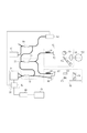
(SS−OCT装置の構成)
図1は、本実施形態における光干渉断層撮像法を用いた撮像装置(OCT装置)の構成例を示す図である。OCT装置は、射出される光周波数が掃引される光源部10と、干渉光を生成するOCT干渉部20と、干渉光を検出する検出部30と、干渉光に基づいて、被検体100の眼底の情報を取得する情報取得部40と、を有している。なお、情報取得部40は、眼底の断層像を取得(生成)する断層像取得部(画像生成部)としても機能する。さらに、OCT装置は、測定アーム50と参照アーム60を有している。
(Configuration of SS-OCT device)
FIG. 1 is a diagram illustrating a configuration example of an imaging apparatus (OCT apparatus) using optical coherence tomography according to the present embodiment. The OCT apparatus includes a
OCT干渉部20は、カプラ21、22を有している。まず、カプラ21は、光源部10から射出された光を眼底へ照射する照射光と参照光とに分岐する。照射光は、測定アーム50を経由して被検体100に照射される。より具体的には、測定アーム50に入射した照射光は、偏光コントローラ51で偏光状態を整えられた後、コリメータ52から空間光として射出される。その後、照射光は、X軸スキャナー53、Y軸スキャナー54、フォーカスレンズ55を介して被検体100の眼底に照射される。なお、X軸スキャナー53、Y軸スキャナー54は眼底を照射光で走査する機能を有する走査部である。走査部によって、照射光の眼底への照射位置が変えられる。そして、眼底からの後方散乱光(反射光)は、再びフォーカスレンズ55、Y軸スキャナー54、X軸スキャナー53、コリメータ52、偏光コントローラ51を経由して測定アーム50から射出される。そして、カプラ21を経由してカプラ22に入射する。
The
一方、参照光は参照アーム60を経由し、カプラ22に入射する。より具体的には、参照アーム60に入射した参照光は、偏光コントローラ61で偏光状態を整えられた後、コリメータ62から空間光として射出される。その後、参照光は分散補償ガラス63、光路長調整光学系64、分散調整プリズムペア65を通り、コリメータレンズ66を介して光ファイバーに入射され、参照アーム60から射出されてカプラ22に入射する。
On the other hand, the reference light enters the
カプラ22で測定アーム50を経由した被検体100の反射光と参照アーム60を通った光とが干渉する。そして、その干渉光を検出部30で検出する。検出部30は、差動検出器31とn個(nは2以上の整数)のA/D変換器を含む変換部32を有している。まず、検出部30では、カプラ22で干渉光を発生させた後すぐに分波された干渉光を差動検出器31で検出する。そして、差動検出器31で電気信号(アナログ信号)に変換されたOCT干渉信号を変換部32でデジタル信号に変換している。そして、デジタル信号が情報取得部40に送られ、デジタル信号に対してフーリエ変換などの周波数分析が行われることで、眼底の情報が得られる。得られた眼底の情報は表示部70によって断層像として表示される。
The reflected light of the subject 100 passing through the
ここで、本実施形態に係る撮像装置は、取得された断層像を解析することにより複数の層をセグメンテーションする解析部を更に有することが好ましく、例えば、情報取得部40を解析部として機能させても良い。このとき、解析部の解析結果に基づいて、複数の層のいずれかの層に沿った平面画像を生成する画像生成部を更に有することが好ましく、例えば、情報取得部40を画像生成部として機能させても良い。そして、平面画像に含まれる眼底の黄斑及び視神経乳頭と断層像に含まれる眼底の黄斑及び視神経乳頭との位置関係が対応付いた状態で、平面画像と断層像とを表示部70に表示させる表示制御部を更に有することが好ましく、例えば、情報取得部40を表示制御部として機能させても良い。これにより、複数の層のいずれかの層に沿った平面画像を広画角の範囲で観察することができるため、診断効率や診断精度を向上することができる。また、眼底の黄斑及び視神経乳頭の断層像を用いて、眼底の黄斑及び視神経乳頭を含む眼底の湾曲情報を演算する演算部を更に有することも好ましく、例えば、情報取得部40を演算部として機能させても良い。これにより、広画角の範囲における眼底の湾曲を定量的に評価できるため、診断効率や診断精度を向上することができる。なお、眼底の黄斑及び視神経乳頭を含む断層像を取得する際には、照射光が1回の走査で黄斑及び視神経乳頭に照射されるように走査部を制御しても良い。また、眼底の3次元断層像を取得した後に、3次元断層像から黄斑及び視神経乳頭を含む断層像を再構成しても良い。
Here, the imaging apparatus according to the present embodiment preferably further includes an analysis unit that performs segmentation on a plurality of layers by analyzing the acquired tomographic image. For example, the
干渉光のサンプリングは、光源部10の外に設けられるkクロック発生部80が発信する等光周波数(等波数)間隔のクロック、いわゆるkクロック信号に基づいて行われる。SS−OCTを含むフーリエドメイン方式のOCTでは、診断に十分な画質を得るために等波数でサンプリングを行うことは不可欠である。したがって、SS−OCTでは、本実施形態のように、kクロック発生部80を設けることが一般的である。k−クロックを用いずとも、例えば光源部10から射出される光周波数が時間に対して正確に線形に変化させれば、等時間間隔のサンプリングでも原則問題は発生しない。しかし、図5(a)に模式的に示すように、一般的な波長可変光源では駆動機構部により共振器長を変化させることにより波長掃引を行っているため時間に対して非線形となるばかりか安定した走引は非常に難しい。又、時として発生するモードホップ(あるタイミングで波長が非連続に変化する現象)による光周波数のずれも生じることから、等時間間隔のサンプリングで正確な距離情報を算出することは困難であるといえる。ただし、本発明はこれに限定されず例えば等間隔でサンプリングし補間等を行なった後、波数空間から実空間へ変換してもかまわない。又、光源部10から射出された光の一部をkクロック発生部80に分岐するために、カプラ90が設けられているが、kクロック発生部80、カプラ90は光源部10に組み込まれていてもよい。
The sampling of the interference light is performed based on a clock at equal optical frequency (equal wave number) intervals, that is, a k-clock signal transmitted from a k-
以上は、被検体100のある1点における断層に関する情報の取得のプロセスであり、このように被検体100の奥行き方向の断層に関する情報を取得することをA−scanと呼ぶ。また、A−scanと直交する方向で被検体の断層に関する情報、すなわち2次元画像を取得するための走査方向をB−scan、更にA−scan、及びB−scanのいずれの走査方向とも直交する方向に走査することをC−scanと呼ぶ。これは、3次元断層像を取得する際に眼底面内に2次元ラスター走査する場合、高速な走査方向がB−scan、B−scanをその直交方向に並べて走査する低速な走査方向をC−scanと呼ぶ。A−scan及びB−scanを行うことで2次元の断層像が得られ、A−scan、B−scan及びC−scanを行うことで、3次元の断層像を得ることができる。B−scan、C−scanは、上述したX軸スキャナー53、Y軸スキャナー54により行われる。
The above is the process of acquiring information on a tomographic slice at a certain point on the subject 100. Acquiring information on a tomographic slice in the depth direction of the subject 100 in this manner is called an A-scan. In addition, the scanning direction for acquiring information on the tomogram of the subject in a direction orthogonal to A-scan, that is, a scanning direction for acquiring a two-dimensional image is orthogonal to any of the scanning directions of B-scan, A-scan, and B-scan. Scanning in the direction is called C-scan. This is because, when performing two-dimensional raster scanning on the fundus oculi when acquiring a three-dimensional tomographic image, the high-speed scanning direction is B-scan, and the low-speed scanning direction in which B-scan is arranged in the orthogonal direction is C-scan. Call it scan. By performing A-scan and B-scan, a two-dimensional tomographic image can be obtained. By performing A-scan, B-scan, and C-scan, a three-dimensional tomographic image can be obtained. The B-scan and the C-scan are performed by the
なお、X軸スキャナー53、Y軸スキャナー54は、それぞれ回転軸が互いに直交するよう配置された偏向ミラーで構成されている。X軸スキャナー53は、X軸方向の走査を行い、Y軸スキャナー54は、Y軸方向の走査を行う。X軸方向、Y軸方向の各方向は、眼球の眼軸方向に対して垂直な方向で、互いに垂直な方向である。また、B−scan、C−scanのようなライン走査方向と、X軸方向またはY軸方向とは、一致していなくてもよい。このため、B−scan、C−scanのライン走査方向は、撮像したい2次元の断層像あるいは3次元の断層像に応じて、適宜決めることができる。
Note that the
また、X軸スキャナー53とY軸スキャナー54をともに駆動させ、偏向ミラーの角度を変えることでさまざまな走査が可能である。例えば、図2(a)、(b)のようなラスター走査でもよいし、図2(c)のように、眼球の一点(例えば黄斑)を複数回通過する方法でもよい。また、図2(d)に示すように眼球の一点(例えば黄斑)を中心としてらせん状に走査を行ってもよい。
In addition, various scans can be performed by driving both the
(走査する角度)
前述のごとく、眼底検査においては広角に撮像したいという要望がある。これを実現するために求められるOCT装置の照射光で走査する範囲(走査角度)について図3の簡単な人眼のモデルを用いて説明する。図3は、眼球を球体として仮定したときの模式図である。眼底の眼球の瞳孔中心にほぼ沿った視軸上に黄斑があり、黄斑から少し離れた位置に視神経乳頭がある。この黄斑と視神経乳頭は、眼底において特に重要な部位である。広角にとは、すなわち、黄斑と視神経乳頭およびその周辺を同一の走査で一度に撮像するということである。
(Scan angle)
As described above, there is a demand for wide-angle imaging in fundus examination. A range (scanning angle) of scanning with irradiation light of the OCT apparatus required to realize this will be described using a simple human eye model in FIG. FIG. 3 is a schematic diagram when the eyeball is assumed to be a sphere. The macula is located on the visual axis substantially along the center of the pupil of the eyeball at the fundus, and the optic disc is located slightly away from the macula. The macula and optic disc are particularly important sites on the fundus. The wide angle means that the macula, the optic papilla and the periphery thereof are imaged at once by the same scan.
標準的な成人の眼底では、黄斑と視神経乳頭間の距離Dは約5.75mmである。照射光は、眼球の瞳孔中心を中心に旋回され、眼底を走査する。黄斑を中心として、視神経乳頭を包含する範囲を同じ走査で撮像する場合、個人差も勘案すると、黄斑と視神経乳頭を結ぶ最短の曲線の長さ(撮像範囲)Lが14mm程度必要である。ここで、この撮像範囲に対応する瞳孔中心を中心に旋回される測定光の振れ角をαとする。成人の眼球の直径の平均は24mm程度なので、撮像範囲Lを14mm以上にするためには、振れ角αは33.4度以上必要になる。この角度は、眼球内の平均屈折率が1.38であることを利用して、空気中の、瞳孔中心に入射する照射光の振れ角βで表すと、arcsin(1.38×sin(33.4度/2))×2≒47度となる。つまり、黄斑を中心に、黄斑と視神経乳頭を同時に撮像するためには、眼底を照射光で線状に走査する場合において、眼底を走査する角度範囲が空気中で換算して47度以上であればよい。なお、以下では、眼底を照射光で線状に走査する場合における眼底を走査する角度範囲を空気中で換算した範囲を画角とする。つまり、振れ角βを画角とする。 In a standard adult fundus, the distance D between the macula and the optic disc is about 5.75 mm. The irradiation light is turned around the center of the pupil of the eyeball and scans the fundus. When the range including the optic papilla is imaged by the same scanning centering on the macula, the length (imaging range) L of the shortest curve connecting the macula and the optic papilla is required to be about 14 mm in consideration of individual differences. Here, the deflection angle of the measurement light turned around the pupil center corresponding to the imaging range is defined as α. Since the average of the diameters of the adult eyeballs is about 24 mm, the deflection angle α needs to be 33.4 degrees or more to make the imaging range L 14 mm or more. Using the fact that the average refractive index in the eyeball is 1.38, the angle is expressed as arcsin (1.38 × sin (33) 0.4 degrees / 2)) × 2 ≒ 47 degrees. In other words, in order to simultaneously image the macula and the optic disc around the macula, when the fundus is linearly scanned with irradiation light, the angle range over which the fundus is scanned should be 47 degrees or more in air. I just need. In the following, a range obtained by converting the angle range in which the fundus is scanned in the air when the fundus is linearly scanned with the irradiation light is defined as an angle of view. That is, the deflection angle β is set as the angle of view.
次に、上記の振れ角βで走査する場合に生じる課題について、図4を用いて説明する。図4は、図3と同様に眼球を球体として仮定したときの模式図である。図4の破線は、走査軌跡を表している。図4で示すように、瞳孔中心から眼球の外壁つまり眼底までの物理的な距離は、黄斑ではa+bであり、黄斑から離れた位置にある部分(角度θ/2の部分)ではaである。a、bは眼軸長の長さTと眼球内の振れ角θを用いると、以下の式で表される。
a=T×cos(θ/2) ・・・式1
a+b=T ・・・式2
このように、瞳孔中心から黄斑までの距離と瞳孔中心から黄斑から離れた位置までの距離とは、bだけ異なる。このbは角度θが大きくなればなるほど、大きくなるため、広画角の眼底検査用のOCT装置では、瞳孔中心から黄斑までの光路長と瞳孔中心から黄斑から離れた周辺の位置までの距離とが大きく異なってしまう。成人の眼軸長Tは個人差が大きく、95%の人が含まれる眼軸長Tの範囲は21mm以上28mm以下である。ここでは、眼軸長Tの値として、その範囲の最大値である28mmを用い、眼球内の振れ角θが33.4度の場合、式1、2からbは約1.2mmとなる。
Next, a problem that occurs when scanning at the above-mentioned deflection angle β will be described with reference to FIG. FIG. 4 is a schematic diagram when the eyeball is assumed to be a sphere similarly to FIG. The dashed line in FIG. 4 represents the scanning trajectory. As shown in FIG. 4, the physical distance from the center of the pupil to the outer wall of the eyeball, that is, the fundus is a + b in the macula, and a in a portion distant from the macula (the angle θ / 2 portion). a and b are expressed by the following equations using the length T of the axial length of the eye and the shake angle θ in the eyeball.
a = T × cos (θ / 2) Equation 1
a + b =
Thus, the distance from the center of the pupil to the macula differs from the distance from the center of the pupil to a position away from the macula by b. Since the angle b increases as the angle θ increases, the OCT apparatus for fundus examination with a wide angle of view has an optical path length from the center of the pupil to the macula and a distance from the center of the pupil to a peripheral position away from the macula. Will be significantly different. The eye axis length T of an adult varies greatly between individuals, and the range of the eye axis length T that includes 95% of the persons is 21 mm or more and 28 mm or less. Here, as the value of the axial length T, 28 mm, which is the maximum value in the range, is used. When the shake angle θ in the eyeball is 33.4 degrees, b is approximately 1.2 mm from
また、眼底検査用のOCT装置で観察する眼底組織は、眼底の表面近傍の網膜とその奥にある脈絡膜である。網膜は最厚部分で0.50mm、脈絡膜は0.30mm程度であるので、眼底検査用のOCT装置は少なくとも0.80mmの深さまで撮像する必要がある。つまり、眼底の表面と脈絡膜との間では、0.8mmの距離の差が生じる。 The fundus tissue observed by the OCT device for fundus examination is the retina near the surface of the fundus and the choroid at the back. Since the retina has a thickness of about 0.50 mm at the thickest portion and a choroid of about 0.30 mm, it is necessary for the OCT apparatus for fundus examination to image to a depth of at least 0.80 mm. That is, there is a difference of 0.8 mm between the surface of the fundus and the choroid.
よって、黄斑と視神経乳頭とを同一の走査で撮像し、かつ視神経乳頭の表面近傍と黄斑の奥にある脈絡膜との情報を得るためには、2×(b+0.80)≒4.0mmの距離差が求められる。この距離差は、空気中の光路差で考えると、4.0mm×1.38≒5.5mmに対応する。つまり、画角47度以上とした場合、得なくてはならない断層情報の深さ範囲(すなわち光路長差)は、空気中で5.5mmとなる。これ以下の深さ範囲しか達成できない場合には眼底周辺部では画像の折り返しが発生するという問題が生じ、正しい撮像が出来ない。一般的に言って、従来市販されているOCT装置では眼底を走査する角度が空気中で換算して約40度程度、深さ範囲(断層像の深さ方向の距離)は脈絡膜―強膜境界まで撮像するため、眼球内で2.6mm程度、空気中で換算して3.6mm程度の深さ範囲に設定されている。従って画角47度以上の広角化を行うことは困難であったと言える。 Accordingly, in order to image the macula and the optic disc with the same scan and obtain information between the vicinity of the surface of the optic disc and the choroid at the back of the macula, a distance of 2 × (b + 0.80) ≒ 4.0 mm A difference is required. This distance difference corresponds to 4.0 mm × 1.38 ≒ 5.5 mm when considered as an optical path difference in the air. That is, when the angle of view is 47 degrees or more, the depth range of the tomographic information (that is, the optical path length difference) that must be obtained is 5.5 mm in the air. If only a depth range smaller than this range can be achieved, there is a problem that image folding occurs around the fundus, and correct imaging cannot be performed. Generally speaking, in conventional OCT apparatuses, the angle at which the fundus is scanned is about 40 degrees in air, and the depth range (the distance in the depth direction of the tomographic image) is the boundary between the choroid and the sclera. The depth range is set to about 2.6 mm in the eyeball and about 3.6 mm in air in order to capture images up to. Therefore, it can be said that it was difficult to widen the angle of view to 47 degrees or more.
(kクロック発生部)
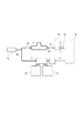
次に、所望の深さ範囲を実現するためのkクロックについて、図6を用いて説明する。図6中の符号は、図1と対応している。kクロック発生部には、例えば、分岐比95:5などのカプラ90により光源から射出される光の一部を分岐し、分岐された光が入射される。その分岐光は、カプラ81によりさらに2つの光路に分岐させ、分岐された光路は第一光路と第二光路として構成される。第一光路と第二光路とは、光路長差82を設けて再びカプラ83で干渉させる。以上がkクロック干渉計である。ここで発生するkクロック干渉信号は、光周波数の時間変化に伴って正弦波となり、かつ光周波数の変化に伴い、この正弦波の周期も時間変化する。図5(b)に示したこの正弦波のゼロクロス点またはピーク点は等波数間隔であるので、これらの点をクロック位置としてサンプリングを行えば波数空間のOCT干渉信号が取得できるのである。
(K clock generator)
Next, k clocks for realizing a desired depth range will be described with reference to FIG. The reference numerals in FIG. 6 correspond to those in FIG. For example, a part of the light emitted from the light source is branched by the
このkクロック干渉信号は、OCT干渉信号をサンプルする変換部32のサンプルクロックとして適切な振幅、電圧へ増幅器等を用いて振幅の補正が行われる。
The k clock interference signal is subjected to amplitude correction using an amplifier or the like to an appropriate amplitude and voltage as a sample clock of the
ここで、kクロックの周波数は、OCT干渉信号のサンプリング周波数であるため、サンプリング定理に基づいて選択される。例えば、図7(a)のようにOCT干渉信号の周波数が、kクロックの周波数の1/2以下であった場合、元の信号を再生できるが、(b)のように1/2以上となった場合、偽の信号を取得することになる。このため、kクロックの周波数は、OCT干渉信号の周波数の2倍以上としなければならない。 Here, since the frequency of the k clock is the sampling frequency of the OCT interference signal, it is selected based on the sampling theorem. For example, when the frequency of the OCT interference signal is less than half the frequency of the k clock as shown in FIG. 7A, the original signal can be reproduced, but as shown in FIG. If so, a false signal will be obtained. For this reason, the frequency of the k clock must be at least twice the frequency of the OCT interference signal.
OCT干渉信号と同一の光源を用いたkクロック干渉計の出力から生成されるkクロックに所望の周波数を与えるには、kクロック干渉計に適切な光路長差を与えればよい。OCT干渉計のサンプル光路は通常、照射光が眼底に照射する光路と反射光が眼底から戻る光路とから成るダブルパスで構成される。これに対して、本実施形態のkクロック干渉計の光路は、図6に示すように、光を分岐させた後、反射させることなく光路長差を設けて再び合波させるというシングルパスで構成されている。したがって、断層像の深さ範囲を空気中で5.5mm以上(眼球内で4.0mm以上)としたい場合には、kクロックの光路長差82は、5.5mmの4倍、すなわち空気中で22mm以上とする必要がある。範囲の4倍以上とすれば良いことになる。
In order to give a desired frequency to the k clock generated from the output of the k clock interferometer using the same light source as the OCT interference signal, an appropriate optical path length difference may be given to the k clock interferometer. The sample optical path of the OCT interferometer is usually constituted by a double path composed of an optical path where the irradiation light irradiates the fundus and an optical path where the reflected light returns from the fundus. On the other hand, as shown in FIG. 6, the optical path of the k-clock interferometer according to the present embodiment is configured by a single path in which light is branched, then the optical path length difference is provided without reflection, and the light is combined again. Have been. Therefore, when it is desired to set the depth range of the tomographic image to be 5.5 mm or more in the air (4.0 mm or more in the eyeball), the optical
(kクロック発生部の干渉計の光路長差とインターリーブ)
しかしながら、このような長いコヒーレンス長の光を発生可能な波長掃引光源は製造が困難かつ非常に高価であり、一般的な眼科機器には不適である。従って、本実施形態に関わるSS−OCT装置では、インターリーブ動作によるサンプリングを行う。インターリーブとは、n個(nは2以上の整数)のA/D変換器を含む変換部32を用いて1つの信号をサンプリングする技術である。一般にA/D変換は、図8(a)に示すようにクロックの立ち上がりエッジまたは立下りエッジのどちらか一方のみで信号を取得している。インターリーブでは、図8(b)に示すように、例えば、位相反転回路などを用いて位相を180度ずらした2つのクロックを2つのA/D変換器に与え、立ち上がりエッジと立下りエッジの両方のエッジで信号を取得することで2倍のサンプリング速度を実現している。すなわち、図10のように、変換部32は、kクロック干渉計の周波数に対応するクロックをn個のA/D変換器に対応するn個のクロックに分割し、分割されたn個のクロックを用いてkクロック干渉計の周波数のn倍の周波数のクロックを生成するように構成されている。なお、図10は、本実施形態に係るインターリーブの回路構成と、干渉信号及びkクロックの様子を表す模式図である。従って、本実施形態においては、kクロックの光路長差82は、空気中で断層像の深さ範囲の2倍の11mm以上とすれば、断層像の深さ範囲を空気中で5.5mm以上(眼球内で4.0mm以上)とすることができる。
(Optical path length difference and interleave of interferometer of k clock generation unit)
However, a wavelength-swept light source capable of generating light having such a long coherence length is difficult and very expensive to manufacture, and is not suitable for general ophthalmic equipment. Therefore, the SS-OCT apparatus according to the present embodiment performs sampling by an interleave operation. The interleaving is a technique of sampling one signal using a
ここで、図10のように変換部32に設けられたn倍の周波数のクロックを生成するためのインターリーブ制御部がインターリーブ動作を切り替えるように構成されても良い。例えば、使用するA/D変換器の数を1つまたは2つまたは4つとするなど複数のパターンを構成しておき、断層像の深さ範囲に応じて各パターンの切り替え制御を行っても良い。
Here, as shown in FIG. 10, the interleave control unit for generating the clock of n times frequency provided in the
SS−OCT装置では画質を高いものとするために等波数間隔で干渉信号を取得することが非常に重要であることは前述した。ところが、kクロック干渉計を用いて、等波数間隔にkクロックを生成した場合であっても、深さ範囲を拡大していくにつれクロック周波数もより高い周波数が要求されることとなり、その伝送過程でこの等波数性が阻害される問題が発生する。前述したインターリーブ動作を行うことで、クロック周波数を半減できるが、それでもシングルエンド信号として伝送した場合、伝送中に信号波形がひずむことで位相ずれが生じると、等波数性が崩れ、断層像上にノイズが発生する要因となる(図9(a))。 As described above, in the SS-OCT apparatus, it is very important to obtain interference signals at equal wave number intervals in order to improve image quality. However, even when k clocks are generated at equal wave number intervals using a k clock interferometer, a higher clock frequency is required as the depth range is expanded, and the transmission process is increased. In this case, a problem that the uniformity is hindered occurs. The clock frequency can be halved by performing the above-described interleaving operation.However, when transmitted as a single-ended signal, if the signal waveform is distorted during transmission and a phase shift occurs, the homogeneity is lost, and the This is a factor that causes noise (FIG. 9A).
したがって、伝送中の波形歪みの影響を少なくするために、kクロックは、例えばLVDS(Low Voltage Differential Signaling)信号などの差動信号85として、すなわち1つの信号を2本の信号線で伝送することが望ましい(図9(b)と(c))。2本の信号線を+側、−側の位相差180度で一対の信号線として結線することにより、この信号線間の電位差が信号レベルとなるため、外部からの同相ノイズが打ち消される(図9(d))。また、差動信号85とすることでスルー・レートが2倍となり、シングルエンド信号に比べてタイミングの不確実さが半分になる。したがって、より高精度に等波数性を保ったままの伝送が可能である。なお、図9は、本実施形態に係るkクロックの周波数に対応するクロックを差動信号として生成することを説明するための図である。
Therefore, in order to reduce the influence of waveform distortion during transmission, the k clock is transmitted as a
ここで、本実施形態に提供可能な実際の数値を用いて、必要なサンプル周波数を示しておく。断層像の深さ範囲(計測距離)Δz、中心波長λc、掃引波長幅Δλとすると、断層像の深さ範囲全体を1度にサンプリングする数であるサンプル数Nは、(4×Δz×Δλ)/λc2から導出される。一方、波長掃引の周波数fAとduty比(1掃引中のOCTとして有効な発光している期間)dとすると、kクロックの周波数fsは、(N×fA)/dから導出される。また、本実施形態に係る光源において、例えば、λc=1040nm、Δλ=110nm、fA=100kHz、d=0.446とする。 Here, the necessary sample frequency is shown using actual numerical values that can be provided in the present embodiment. Assuming that the depth range of the tomographic image (measurement distance) Δz, the center wavelength λc, and the sweep wavelength width Δλ, the number of samples N, which is the number of sampling the entire depth range of the tomographic image at a time, is (4 × Δz × Δλ). ) / Λc 2 . On the other hand, assuming that the frequency fA of the wavelength sweep is a duty ratio (a period during which light emission is effective as OCT during one sweep) d, the frequency fs of the k clock is derived from (N × fA) / d. In the light source according to the present embodiment, for example, λc = 1040 nm, Δλ = 110 nm, fA = 100 kHz, and d = 0.446.
断層像の深さ範囲が空気中で5.5mm(眼球内で4.0mm)である場合に、サンプル数Nは、(4×5.5×106×110)/10402=2237と導出される。また、この場合、kクロックの周波数fsは、(2237×100×103)/0.446=501.57MHzと導出される。ここで、2つのA/D変換器を用いたインターリーブによりサンプリングを行うので、1つのA/D変換器に対するクロック周波数は、501.57MHz/2=250.64MHzである。 When the depth range of the tomographic image is 5.5 mm in the air (4.0 mm in the eyeball), the sample number N is derived as (4 × 5.5 × 10 6 × 110) / 10402 2 = 2237. Is done. In this case, the frequency fs of the k clock is derived as (2237 × 100 × 10 3 ) /0.446=501.57 MHz. Here, since sampling is performed by interleaving using two A / D converters, the clock frequency for one A / D converter is 501.57 MHz / 2 = 250.64 MHz.
又、前述した従来市販されているOCT装置の構成に本実施形態を適用した場合は、次のように考えると良い。深さ範囲が従来の空気中で3.6mm(眼球内で2.6mm)である場合、サンプル数は、(4×3.6×106×110)/10402=1464と導出される。また、この場合、kクロックの周波数fsは、(1464×100×103)/0.446=328.25MHzと導出されるが、本実施形態に従い、2つのA/D変換器を用いたインターリーブによりサンプリングを行った場合には、サンプル数は1464×2=2928となり、kクロックの周波数fsは、328.25×2=656.5MHz。従って空気中で7.2mm(眼球内で5.2mm)の断層像が取得できる。 When the present embodiment is applied to the configuration of the conventional commercially available OCT apparatus described above, the following may be considered. When the depth range is 3.6mm in conventional air (2.6 mm in the eye), the number of samples is derived as (4 × 3.6 × 10 6 × 110) / 1040 2 = 1464. In this case, the frequency fs of the k clock is derived as (1464 × 100 × 10 3 ) /0.446=328.25 MHz. According to the present embodiment, the interleaving using two A / D converters is performed. , The number of samples is 1464 × 2 = 2928, and the frequency fs of the k clock is 328.25 × 2 = 656.5 MHz. Therefore, a tomographic image of 7.2 mm in the air (5.2 mm in the eyeball) can be obtained.
以上説明したように、本実施形態の構成をとれば、クロック信号伝送中の信号波形歪による位相ずれ引き起こす画質の劣化の無い状態で、画角47度以上の広角撮像において必要となる断層像の深さ範囲が空気中で5.5mm(眼球内で4.0mm)を一つのA/D変換器あたりに対するクロック周波数を250.64MHzと、従来市販されているOCT装置で使われているkクロックの周波数328.25MHzよりも低い周波数で達成できる。また、一つのA/D変換器あたりに対するクロック周波数を従来市販されているOCT装置で使われている周波数328.25MHzを用いても空気中で7.2mm(眼球内で5.2mm)の断層像が取得できるということになる。すなわち、眼底の広範囲で1回の走査を行った際に、眼底の所望の深さ範囲の断層像を網羅的に取得することができるのである。 As described above, according to the configuration of the present embodiment, a tomographic image required for wide-angle imaging at an angle of view of 47 degrees or more without deterioration in image quality causing a phase shift due to signal waveform distortion during clock signal transmission. The clock frequency per A / D converter is 5.5 mm in the air with a depth range of 5.5 mm (4.0 mm in the eyeball), and the clock frequency is 250.64 MHz. At a frequency lower than 328.25 MHz. Even if the clock frequency for one A / D converter is 328.25 MHz, which is the frequency used in a conventional OCT apparatus, 7.2 mm in the air (5.2 mm in the eyeball) is used. This means that an image can be obtained. That is, when one scan is performed over a wide range of the fundus, a tomographic image of a desired depth range of the fundus can be comprehensively acquired.
なお、本発明は、眼底の広範囲で1回の走査を行った際に限定されない。すなわち、走査部が、眼底において照射光を走査する角度が空気中で換算して47度以上となるように構成されている場合に限定されない。走査する角度に関係なく、深さ範囲において眼球内で4.0mm以上となる範囲の眼底の断層像を取得したい場合に、kクロック発生部は、インターリーブでサンプリングすることを考慮し、眼球内で4.0mm以上となる範囲に対応する光路長差となるように構成されていれば良い。このとき、上述したように、kクロック発生部は、第二光路がシングルパスで構成されており、かつ、位相を180度ずらした2つのクロックと2つのA/D変換器を用いたインターリーブによるサンプリングを行うのであれば、光路長差が空気中で11mm以上となるように構成されることが好ましい。また、kクロック発生部は、第二光路がダブルパスで構成されていれば、光路長差が空気中で5.5mm以上となるように構成されることが好ましい。また、kクロック発生部は、光路長差をこれらの長さにする代わりに、サンプリングの数やクロックの周波数を疑似的に変更するように構成されても同等の効果を得ることができる。 The present invention is not limited to the case where one scan is performed over a wide range of the fundus. That is, the present invention is not limited to the case where the scanning unit is configured to scan the irradiation light on the fundus at an angle of 47 degrees or more in air. Regardless of the scanning angle, when it is desired to obtain a tomographic image of the fundus within a range of 4.0 mm or more in the depth range of the eyeball, the k clock generation unit considers interleaving sampling, and What is necessary is just to be comprised so that it may become an optical path length difference corresponding to the range which becomes 4.0 mm or more. At this time, as described above, the k clock generating unit performs interleaving using two clocks whose phases are shifted by 180 degrees and two A / D converters, in which the second optical path is configured by a single path. If sampling is performed, it is preferable that the optical path length difference be 11 mm or more in air. In addition, it is preferable that the k clock generation unit be configured such that the optical path length difference becomes 5.5 mm or more in air if the second optical path is configured by a double path. Further, the same effect can be obtained even if the k clock generation unit is configured to artificially change the number of samplings and the frequency of the clock instead of setting the optical path length difference to these lengths.
なお、kクロックの光路長差82は、シングルパスで構成されている場合には空気中で13.8mm、ダブルパスで構成されている場合には空気中で6.9mmとしても良い。このとき、断層像の深さ範囲が空気中で6.9mm以上(眼球内5.0mm以上)となるように構成することができる。また、kクロックの光路長差82は、シングルパスで構成されている場合には空気中で16mm、ダブルパスで構成されている場合には空気中で8mmとしても良い。このとき、断層像の深さ範囲が空気中で8.0mm以上(眼球内5.8mm以上)となるように構成することができる。
The optical
(その他の実施形態)
また、本実施形態に係る撮像装置は、走査する角度の異なる複数の撮像モードを選択する選択部を更に有することが好ましい。このとき、制御部は、選択された撮像モードによって、走査する角度を変更するように走査部を制御する。例えば、黄斑と視神経乳頭とを両方含む断層像として撮像する撮像モード(広画角撮像モード)では走査する角度が47度以上である第1の角度とし、黄斑と視神経乳頭とのいずれか一方を撮像する撮像モード(狭画角撮像モード)では、47度未満である第2の角度まで変更可能とする。
(Other embodiments)
Further, it is preferable that the imaging device according to the present embodiment further includes a selection unit that selects a plurality of imaging modes having different scanning angles. At this time, the control unit controls the scanning unit to change the scanning angle according to the selected imaging mode. For example, in an imaging mode (wide-angle imaging mode) for imaging as a tomographic image including both the macula and the optic disc, the scanning angle is set to a first angle of 47 degrees or more, and one of the macula and the optic disc is set. In the imaging mode for capturing images (narrow angle of view imaging mode), the angle can be changed to a second angle of less than 47 degrees.
またこの時、選択部は走査する角度を変更に基づいて、深さ範囲を同時に4.0mm以上である第1の範囲から眼球内で4.0mm未満である第2の範囲まで変更する。この深さ範囲の変更を行うためのkクロック発生部の構成を図6を用いて以下に説明する。 In addition, at this time, the selection unit changes the depth range from the first range of 4.0 mm or more to the second range of less than 4.0 mm in the eyeball at the same time based on the change of the scanning angle. The configuration of the k clock generator for changing the depth range will be described below with reference to FIG.
前述のごとく、kクロックの周波数はkクロック干渉計の光路長差82に対応する。従って第一光路に対して光路長差を有する第二光路において、例えば、屈折率を変更可能な物質(ガス等)を設ける、ファイバーから一度空気中に光を射出してファイバーに戻すような構成で、ファイバー端同士の光学的な距離を変更する、または、一度ファイバーの外に光を射出する上記構成において、折り返しミラーを複数個用いて、可動ステージに設けた折り返しミラーを光軸方向に移動させる等の方法により光路長差を変更することが出来る。
As described above, the frequency of the k clock corresponds to the optical
このとき、制御部は、選択された撮像モードによって、走査する角度とこの光路長差とを変更するように、走査部と変更部とを制御することになる。この変更部は例えばインターリーブ動作を用いたとき、光路長差が11mm以上である第1の光路長差から11mm未満である第2の光路長差まで変更可能に構成されていることが好ましい。この変更部の盛業は、前述の断層像取得部内のインターリーブ制御部においてインターリーブ動作の切り替えに伴う断層像の深さ範囲切り替えにも用いられる。 At this time, the control unit controls the scanning unit and the changing unit such that the scanning angle and the optical path length difference are changed according to the selected imaging mode. It is preferable that the change unit is configured to be able to change from a first optical path length difference of 11 mm or more to a second optical path length difference of less than 11 mm, for example, when an interleave operation is used. The success of the changing unit is also used for switching the depth range of the tomographic image accompanying the switching of the interleaving operation in the interleave control unit in the above-described tomographic image acquiring unit.
さらに、選択部は、眼の硝子体と網膜と脈絡膜とを含むように撮像する撮像モード(硝子体観察モード)を含む複数の撮像モードのうちいずれかの撮像モードを選択可能に構成されても良い。このとき、眼の硝子体と網膜と脈絡膜とを含むように撮像する撮像モードが選択されると、例えば、深さ範囲において眼球内で4.0mm以上の範囲の眼底の断層像が取得されることが好ましい。この時撮像範囲を広角化することは必須ではないが、本撮影モードにおける深さ範囲切り替えに有効である。これは、眼の硝子体と網膜と脈絡膜とが十分に含まれるように断層撮像するには、深さ範囲において眼球内で4.0mm以上の範囲は必要となるためである。 Furthermore, the selection unit may be configured to be able to select any one of a plurality of imaging modes including an imaging mode (vitreous observation mode) for imaging so as to include the vitreous, retina, and choroid of the eye. good. At this time, when an imaging mode for imaging so as to include the vitreous body, retina, and choroid of the eye is selected, for example, a tomographic image of the fundus in a range of 4.0 mm or more in the eyeball in the depth range is acquired. Is preferred. At this time, it is not essential to widen the imaging range, but it is effective for switching the depth range in the main imaging mode. This is because, in order to perform tomographic imaging so that the vitreous body, retina, and choroid of the eye are sufficiently included, a depth range of 4.0 mm or more in the eyeball is required.
尚、いずれの撮像モードであってもモードの選択により撮像する深さ範囲を変える場合、kクロック発生部は、光路長差を変更する代わりに、後述するサンプリングの数やクロックの周波数を疑似的に変更するように構成されても同等の効果を得ることができる。ここで擬似的とは、例えば、深さ範囲を狭くする場合、kクロック発生部はサンプリングの数やクロックの周波数を少なくするように構成しても良いが、単にデータの間引き等、利用するデータ数減少させるだけでもA−スキャンの距離データの算出時間を短縮できるという効果がある。 When the depth range to be imaged is changed by selecting the mode in any of the imaging modes, the k-clock generation unit simulates the number of samplings and the frequency of the clock described later instead of changing the optical path length difference. The same effect can be obtained even if it is configured to change to. Here, the term “simulated” means that, for example, when the depth range is narrowed, the k clock generation unit may be configured to reduce the number of samplings and the frequency of the clock. There is an effect that the calculation time of the distance data of the A-scan can be shortened by simply reducing the number.
また、本発明は、以下の処理を実行することによっても実現される。即ち、上述した実施形態の機能を実現するソフトウェア(プログラム)を、ネットワーク又は各種記憶媒体を介してシステム或いは装置に供給し、そのシステム或いは装置のコンピュータ(またはCPUやMPU等)がプログラムを読み出して実行する処理である。 The present invention is also realized by executing the following processing. That is, software (program) that realizes the functions of the above-described embodiments is supplied to a system or apparatus via a network or various storage media, and a computer (or CPU, MPU, or the like) of the system or apparatus reads the program and reads the program. This is the process to be performed.
Claims (15)
前記眼底において前記照射光を走査する走査部と、
前記干渉部により干渉して得た干渉光を検出する検出部と、
前記検出部が前記干渉光を検出して得たアナログ信号をデジタル信号に変換する変換部と、
前記光源部から射出された光のうち一部の光が通る光路が第一光路と前記第一光路に対して光路長差を有する第二光路とに分岐された干渉計として構成され、前記変換部が前記アナログ信号を前記光路長差に対応する周波数でサンプリングするためのクロックであって、所定の波数間隔で立ち上がり及び立ち下がりを交互に繰り返すクロックを生成するクロック発生部と、
前記生成されたクロックにより前記変換部がサンプリングした前記アナログ信号を変換して得た前記デジタル信号に基づいて、前記眼底の断層像を取得する断層像取得部と、を有する撮像装置であって、
前記走査部は、前記眼底において前記照射光を走査する角度が空気中で換算して47度以上となるように構成されており、
前記変換部は、前記光路長差に対応する周波数のクロックから得た2つのクロックであって、所定の波数間隔で立ち上がり及び立ち下がりを交互に繰り返す2つのクロックのうち一方に対して他方を反転する反転回路と、前記一方を用いて前記アナログ信号をサンプリングするための第1のA/D変換器と、前記反転された他方を用いて前記アナログ信号をサンプリングするための第2のA/D変換器と、を含み、前記第1のA/D変換器及び前記第2のA/D変換器が前記アナログ信号をサンプリングすることにより、前記光路長差に対応する周波数よりも高い周波数のクロックにより前記アナログ信号をサンプリングするように構成されていることを特徴とする撮像装置。 The light emitted from the light source section that sweeps the wavelength of the emitted light is split into irradiation light and reference light that irradiate the fundus, and the reflected light from the fundus irradiated with the irradiation light interferes with the reference light. Interference part,
A scanning unit that scans the irradiation light at the fundus,
A detection unit that detects interference light obtained by interfering with the interference unit,
A conversion unit that converts an analog signal obtained by detecting the interference light by the detection unit into a digital signal,
An optical path through which a part of the light emitted from the light source unit passes is configured as an interferometer branched into a first optical path and a second optical path having an optical path length difference with respect to the first optical path, and the conversion is performed. A clock generating unit that generates a clock that is a clock for sampling the analog signal at a frequency corresponding to the optical path length difference, and that alternately repeats rising and falling at predetermined wavenumber intervals ;
An imaging apparatus comprising: a tomographic image acquisition unit configured to acquire a tomographic image of the fundus, based on the digital signal obtained by converting the analog signal sampled by the conversion unit using the generated clock,
The scanning unit is configured such that the angle at which the irradiation light is scanned in the fundus becomes 47 degrees or more in air.
The converting unit is a two clock obtained from a clock of a frequency corresponding to the previous Kihikariro length difference, the other with respect to one of the two clocks repeating rise and fall alternately at predetermined wave number intervals Circuit, a first A / D converter for sampling the analog signal using the one, and a second A / D converter for sampling the analog signal using the inverted one. / D converter, wherein the first A / D converter and the second A / D converter sample the analog signal so that the frequency is higher than the frequency corresponding to the optical path length difference. An imaging device configured to sample the analog signal in response to the clock signal.
前記2本の信号線を伝送した2つのクロックに生じるノイズが打ち消されるように、前記2本の信号線が1本の信号線として結線されることによって、信号線を伝送する際にクロックに生じるノイズが低減された状態で、所定の波数間隔で立ち上がり及び立ち下がりを交互に繰り返すクロックが前記変換部に伝送されるように構成されることを特徴とする請求項6に記載の撮像装置。The two signal lines are connected as one signal line so that noise generated in the two clocks transmitted through the two signal lines is canceled, so that the clock is generated when transmitting the signal lines. The imaging apparatus according to claim 6, wherein a clock that alternately rises and falls at predetermined wave number intervals is transmitted to the conversion unit in a state where noise is reduced.
前記制御部は、前記狭画角撮像モードが選択された場合、前記第2の角度で前記照射光が走査されるように前記走査部を制御することを特徴とする請求項8に記載の撮像装置。 Further comprising a selection unit for selecting any one of a plurality of imaging modes including a narrow angle of view imaging mode to image any one of the macula of the fundus and the optic disc,
The imaging device according to claim 8 , wherein the control unit controls the scanning unit so that the irradiation light is scanned at the second angle when the narrow angle-of-view imaging mode is selected. apparatus.
前記制御部は、前記広画角撮像モードが選択された場合、前記第1の角度で前記照射光が走査されるように前記走査部を制御することを特徴とする請求項9に記載の撮像装置。 The plurality of imaging modes further include a wide-angle imaging mode for imaging the macula of the fundus and the optic disc,
The imaging apparatus according to claim 9 , wherein when the wide-angle imaging mode is selected, the control unit controls the scanning unit so that the irradiation light is scanned at the first angle. apparatus.
前記制御部は、前記硝子体観察モードが選択された場合、前記第2の角度で前記照射光が走査されるように前記走査部を制御し、
前記変換部は、前記断層像の深さ範囲が4.0mm以上である範囲になるように、前記アナログ信号をサンプリングするためのクロックを切り替えることを特徴とする請求項9乃至11のいずれか1項に記載の撮像装置。 The plurality of imaging modes may include a vitreous observation mode for observing the nitric transducer body,
The control unit, when the vitreous observation mode is selected, controls the scanning unit so that the irradiation light is scanned at the second angle,
The converting unit, as the depth range of the tomographic image is in the range is 4.0mm or more, any one of claims 9 to 1 1, characterized in that to switch the clock for sampling the analog signal 2. The imaging device according to claim 1.
Priority Applications (2)
| Application Number | Priority Date | Filing Date | Title |
|---|---|---|---|
| JP2015175020A JP6632266B2 (en) | 2015-09-04 | 2015-09-04 | Imaging device |
| US15/246,202 US10537242B2 (en) | 2015-09-04 | 2016-08-24 | Imaging apparatus |
Applications Claiming Priority (1)
| Application Number | Priority Date | Filing Date | Title |
|---|---|---|---|
| JP2015175020A JP6632266B2 (en) | 2015-09-04 | 2015-09-04 | Imaging device |
Publications (3)
| Publication Number | Publication Date |
|---|---|
| JP2017047110A JP2017047110A (en) | 2017-03-09 |
| JP2017047110A5 JP2017047110A5 (en) | 2018-10-25 |
| JP6632266B2 true JP6632266B2 (en) | 2020-01-22 |
Family
ID=58189821
Family Applications (1)
| Application Number | Title | Priority Date | Filing Date |
|---|---|---|---|
| JP2015175020A Active JP6632266B2 (en) | 2015-09-04 | 2015-09-04 | Imaging device |
Country Status (2)
| Country | Link |
|---|---|
| US (1) | US10537242B2 (en) |
| JP (1) | JP6632266B2 (en) |
Families Citing this family (13)
| Publication number | Priority date | Publication date | Assignee | Title |
|---|---|---|---|---|
| JP6685673B2 (en) * | 2015-05-01 | 2020-04-22 | キヤノン株式会社 | Imaging device |
| JP2017201257A (en) * | 2016-05-06 | 2017-11-09 | 株式会社トーメーコーポレーション | Optical tomographic image imaging apparatus |
| CA3048197A1 (en) | 2016-12-21 | 2018-06-28 | Acucela Inc. | Miniaturized mobile, low cost optical coherence tomography system for home based ophthalmic applications |
| EP3574282B1 (en) * | 2017-01-24 | 2021-11-24 | Alcon Inc. | Dynamic mode switching for multi-mode ophthalmic optical coherence tomography |
| CN107661089A (en) * | 2017-09-19 | 2018-02-06 | 北京工业大学 | A kind of domain optical coherence chromatographs continuous dispersion compensation imaging method and system |
| US10767973B2 (en) * | 2017-11-02 | 2020-09-08 | Alcon Inc. | Dual-edge sampling with k-clock to avoid aliasing in optical coherence tomography |
| CN107862661B (en) * | 2017-11-06 | 2019-11-29 | 郑州轻工业学院 | A kind of optical coherence tomography system method for correcting image |
| JP7402866B2 (en) | 2018-06-20 | 2023-12-21 | アキュセラ インコーポレイテッド | Miniaturized mobile low-cost optical coherence tomography system for home ophthalmology applications |
| WO2021134087A1 (en) | 2019-12-26 | 2021-07-01 | Acucela Inc. | Optical coherence tomography patient alignment system for home based ophthalmic applications |
| US10959613B1 (en) | 2020-08-04 | 2021-03-30 | Acucela Inc. | Scan pattern and signal processing for optical coherence tomography |
| US11393094B2 (en) | 2020-09-11 | 2022-07-19 | Acucela Inc. | Artificial intelligence for evaluation of optical coherence tomography images |
| CA3192083A1 (en) | 2020-09-30 | 2022-04-07 | Acucela Inc. | Myopia prediction, diagnosis, planning, and monitoring device |
| US11497396B2 (en) | 2021-03-24 | 2022-11-15 | Acucela Inc. | Axial length measurement monitor |
Family Cites Families (16)
| Publication number | Priority date | Publication date | Assignee | Title |
|---|---|---|---|---|
| JP4369074B2 (en) * | 2001-05-11 | 2009-11-18 | ジーイー・メディカル・システムズ・グローバル・テクノロジー・カンパニー・エルエルシー | High-speed AD conversion signal processing apparatus, digital receiver front-end circuit, and MRI apparatus |
| ES2534572T3 (en) * | 2007-01-10 | 2015-04-24 | Lightlab Imaging, Inc. | Methods and apparatus for scanning optical coherence tomography |
| JP5129562B2 (en) * | 2007-12-27 | 2013-01-30 | 富士フイルム株式会社 | Optical tomographic imaging method and system |
| US8478384B2 (en) * | 2010-01-19 | 2013-07-02 | Lightlab Imaging, Inc. | Intravascular optical coherence tomography system with pressure monitoring interface and accessories |
| JP5727198B2 (en) * | 2010-11-05 | 2015-06-03 | 株式会社ニデック | Ophthalmic equipment |
| JP5735790B2 (en) | 2010-12-02 | 2015-06-17 | 株式会社ニデック | Ophthalmic imaging equipment |
| WO2012098194A1 (en) * | 2011-01-21 | 2012-07-26 | Carl Zeiss Meditec Ag | Methods, systems and applications of variable imaging depth in fourier domain optical coherence tomography |
| US8446308B2 (en) * | 2011-04-21 | 2013-05-21 | Kabushiki Kaisha Toshiba | Apparatus for detection of a leading edge of a photo sensor output signal |
| JP2014016181A (en) * | 2012-07-06 | 2014-01-30 | Canon Inc | Optical coherence tomographic imaging apparatus |
| JP5836493B2 (en) * | 2012-09-07 | 2015-12-24 | 株式会社日立製作所 | Interleaved A / D converter |
| JP2016504589A (en) * | 2012-12-20 | 2016-02-12 | ナサニエル ジェイ. ケンプ, | Optical coherence tomography system reconfigurable between different imaging modes |
| US9295386B2 (en) * | 2013-04-03 | 2016-03-29 | Kabushiki Kaisha Topcon | Ophthalmologic apparatus |
| US20140340634A1 (en) * | 2013-04-05 | 2014-11-20 | Wasatch Photonics, Inc. | Optical coherence tomography systems and methods |
| JP2015102537A (en) * | 2013-11-28 | 2015-06-04 | キヤノン株式会社 | Optical interference tomograph meter |
| JP6292860B2 (en) | 2013-12-17 | 2018-03-14 | キヤノン株式会社 | Optical coherence tomography |
| JP5987186B1 (en) | 2015-06-17 | 2016-09-07 | 学校法人北里研究所 | Wavelength scanning optical coherence tomography apparatus and tomography method |
-
2015
- 2015-09-04 JP JP2015175020A patent/JP6632266B2/en active Active
-
2016
- 2016-08-24 US US15/246,202 patent/US10537242B2/en active Active
Also Published As
| Publication number | Publication date |
|---|---|
| JP2017047110A (en) | 2017-03-09 |
| US20170065169A1 (en) | 2017-03-09 |
| US10537242B2 (en) | 2020-01-21 |
Similar Documents
| Publication | Publication Date | Title |
|---|---|---|
| JP6632266B2 (en) | Imaging device | |
| JP6685673B2 (en) | Imaging device | |
| JP6765786B2 (en) | Image pickup device, operation method of image pickup device, information processing device, and operation method of information processing device | |
| WO2016178298A1 (en) | Imaging apparatus | |
| JP2016209577A (en) | Ophthalmologic imaging device | |
| JP6465557B2 (en) | Tomography equipment | |
| JP2015102537A (en) | Optical interference tomograph meter | |
| JP2017047110A5 (en) | ||
| WO2019035441A1 (en) | Measurement device | |
| JP2015114284A (en) | Optical coherence tomography | |
| JP7146911B2 (en) | Dual Edge Sampling with k Clocks to Avoid Aliasing in Optical Coherence Tomography | |
| CN110199171B (en) | Dynamic mode switching for multi-mode ophthalmic optical coherence tomography | |
| WO2019035426A1 (en) | Measurement device | |
| JP2019063044A (en) | OCT apparatus and OCT apparatus control program | |
| JP2018187038A (en) | Optical coherence tomographic imaging apparatus | |
| JP2020106514A (en) | Optical coherence tomographic imaging device | |
| JP6584125B2 (en) | Imaging device | |
| JP2017096884A (en) | Image capturing device | |
| JP7218122B2 (en) | Ophthalmic imaging device and its control method | |
| JP2012183152A (en) | Method and device for measuring light interference | |
| WO2019082840A1 (en) | Ophthalmological imaging device and control method for same | |
| JP2017096885A (en) | Image capturing device |
Legal Events
| Date | Code | Title | Description |
|---|---|---|---|
| A621 | Written request for application examination |
Free format text: JAPANESE INTERMEDIATE CODE: A621 Effective date: 20180821 |
|
| A521 | Written amendment |
Free format text: JAPANESE INTERMEDIATE CODE: A523 Effective date: 20180912 |
|
| A977 | Report on retrieval |
Free format text: JAPANESE INTERMEDIATE CODE: A971007 Effective date: 20190411 |
|
| A131 | Notification of reasons for refusal |
Free format text: JAPANESE INTERMEDIATE CODE: A131 Effective date: 20190416 |
|
| A521 | Written amendment |
Free format text: JAPANESE INTERMEDIATE CODE: A523 Effective date: 20190617 |
|
| TRDD | Decision of grant or rejection written | ||
| A01 | Written decision to grant a patent or to grant a registration (utility model) |
Free format text: JAPANESE INTERMEDIATE CODE: A01 Effective date: 20191112 |
|
| A61 | First payment of annual fees (during grant procedure) |
Free format text: JAPANESE INTERMEDIATE CODE: A61 Effective date: 20191210 |
|
| R151 | Written notification of patent or utility model registration |
Ref document number: 6632266 Country of ref document: JP Free format text: JAPANESE INTERMEDIATE CODE: R151 |