JP6765786B2 - Image pickup device, operation method of image pickup device, information processing device, and operation method of information processing device - Google Patents
Image pickup device, operation method of image pickup device, information processing device, and operation method of information processing device Download PDFInfo
- Publication number
- JP6765786B2 JP6765786B2 JP2015093998A JP2015093998A JP6765786B2 JP 6765786 B2 JP6765786 B2 JP 6765786B2 JP 2015093998 A JP2015093998 A JP 2015093998A JP 2015093998 A JP2015093998 A JP 2015093998A JP 6765786 B2 JP6765786 B2 JP 6765786B2
- Authority
- JP
- Japan
- Prior art keywords
- light
- analog
- fundus
- interference
- data sets
- Prior art date
- Legal status (The legal status is an assumption and is not a legal conclusion. Google has not performed a legal analysis and makes no representation as to the accuracy of the status listed.)
- Active
Links
Images


Classifications
-
- A—HUMAN NECESSITIES
- A61—MEDICAL OR VETERINARY SCIENCE; HYGIENE
- A61B—DIAGNOSIS; SURGERY; IDENTIFICATION
- A61B3/00—Apparatus for testing the eyes; Instruments for examining the eyes
- A61B3/10—Objective types, i.e. instruments for examining the eyes independent of the patients' perceptions or reactions
- A61B3/102—Objective types, i.e. instruments for examining the eyes independent of the patients' perceptions or reactions for optical coherence tomography [OCT]
Description
本発明は、光干渉断層像を撮像する撮像装置、該撮像装置の作動方法、該撮像装置と接続される情報処理装置、及び該情報処理装置の作動方法に関する。 The present invention relates to an image pickup device that captures an optical interference tomographic image, an operation method of the image pickup device, an information processing device connected to the image pickup device, and an operation method of the information processing device.
光干渉断層撮像法(Optical Coherence Tomography、以下OCTという)を用いる撮像装置(以下、OCT装置という)が開発されている(特許文献1)。OCT装置では、物体へ光を照射し、その際に該照射光の波長を変化させ、該照射光が物体の異なる深さから戻ることで得られる反射光と、該照射光に対応する参照光とを干渉させている。そして、該干渉光の強度の時間波形(以下、干渉スペクトルと略す)に含まれる周波数成分を分析することによって物体の断層に関する情報、具体的には断層像を得ている。このようなOCT装置は、例えば眼底検査に用いられる。 An imaging device (hereinafter referred to as an OCT device) using an optical coherence tomography (hereinafter referred to as OCT) has been developed (Patent Document 1). In the OCT device, the reflected light obtained by irradiating an object with light, changing the wavelength of the irradiation light, and returning the irradiation light from different depths of the object, and the reference light corresponding to the irradiation light. Is interfering with. Then, by analyzing the frequency component included in the time waveform of the intensity of the interference light (hereinafter, abbreviated as the interference spectrum), information on the tomography of the object, specifically, a tomographic image is obtained. Such an OCT device is used, for example, for fundus examination.
眼の疾患は、完治困難な疾患が多いため、眼底の病変部を早期に発見し、病変部が眼底の広範囲にまで進行することを遅らせる治療を早期に開始することが重要である。特に、病変部が黄班にまで進行すると、視覚に甚大な影響を与えるため、病変部が黄班から十分離れた位置にあっても、その病変部を発見したいという要求がある。この要求に答えるため、眼底検査に用いられるOCT装置の広画角化が期待されている。 Since many eye diseases are difficult to cure completely, it is important to detect the lesion in the fundus at an early stage and start treatment to delay the progression of the lesion to a wide area of the fundus at an early stage. In particular, when the lesion progresses to the macula, it has a great effect on vision, so there is a demand to find the lesion even if the lesion is sufficiently distant from the macula. In order to meet this demand, widening the angle of view of the OCT device used for fundus examination is expected.
このような期待に応える技術として、特許文献1では、眼底の断層像の観察領域を広範囲とするために複数の断層像をつなぎ合わせて広範囲の断層像を構成することが開示されている。また、特許文献1には、波長可変光源を用いたOCT装置(Swept Source OCT装置、以下SS−OCT装置という)について開示されており、その波長可変光源として、ファイバーリング共振器、及び波長選択フィルタが例示されている。
As a technique for meeting such expectations,
しかし、特許文献1の方法では、取得した複数の断層像を連続的につなぎ合わせるための画像処理に時間や手間がかかる。そのため、1回の撮像で広範囲にわたる断層情報を取得することが好ましい。この場合、眼球は略球体であるため、眼底の中央部と周辺部では、照射光の光路長が大きく異なってしまう。従って、従来の構成のOCT装置では、断層に関する情報を広範囲にわたって精度よく得ることができない場合がある。
However, in the method of
本発明は上述した課題に対するものであって、1回の走査の撮像範囲を大きくしても断層に関する情報を精度よく取得する撮像装置、該撮像装置の作動方法、該撮像装置と接続される情報処理装置、及び該情報処理装置の作動方法を提供することを目的とする。 The present invention relates to the above-mentioned problems, and is an imaging device that accurately acquires information on a tomographic image even if the imaging range of one scan is increased, an operating method of the imaging device, and information connected to the imaging device. It is an object of the present invention to provide a processing apparatus and a method of operating the information processing apparatus.
以上の課題を解決するために、本発明に係る撮像装置の一つは、
射出する光の波長が掃引される波長掃引光源を含む光源部と、
前記射出された光を被検眼の眼底へ照射する照射光と参照光とに分割し、前記眼底からの前記照射光の反射光と前記参照光とによる干渉光を発生させる干渉部と、
前記干渉光を検出する検出部と、
前記検出された干渉光のアナログ信号を分割して得た少なくとも二つのアナログ信号であって、前記光源部に含まれる同一の波長掃引光源から射出された光に基づく少なくとも二つのアナログ信号をアナログデジタル変換する少なくとも二つの変換部と、
前記アナログデジタル変換して得た少なくとも二つのデータセット各々のインデックスの関連付けを行う関連付け手段と、
前記関連付けられたインデックスを用いて前記少なくとも二つのデータセットを統合して等波数間隔のデータセットを生成する生成手段と、
前記生成された等波数間隔のデータセットを用いて前記眼底の画像を生成する画像生成手段と、
を備えることを特徴とする。
In order to solve the above problems, one of the imaging devices according to the present invention is
A light source unit including a wavelength sweep light source in which the wavelength of the emitted light is swept, and
An interference portion that divides the emitted light into an irradiation light that irradiates the fundus of the eye to be inspected and a reference light, and generates an interference light due to the reflected light of the irradiation light from the fundus and the reference light.
The detection unit that detects the interference light and
At least two analog signals obtained by dividing the analog signal of the detected interference light, and at least two analog signals based on the light emitted from the same wavelength sweep light source included in the light source unit are analog-digital. At least two converters to convert,
An association means for associating the indexes of at least two data sets obtained by the analog-to-digital conversion, and
A generation means that integrates the at least two data sets using the associated index to generate a data set with equal wavenumber intervals.
An image generation means for generating an image of the fundus using the generated data set of equal wave number intervals, and
It is characterized by having.
本発明によれば、1回の走査の撮像範囲を大きくしても断層に関する情報を精度よく取得することができる。 According to the present invention, it is possible to accurately acquire information on a tomographic image even if the imaging range of one scan is increased.
以下、本発明の実施形態について、図面を参照して説明する。以下の説明では本発明として撮像装置の態様を例示しているが、当該撮像装置を作動させる方法の例示としても把握可能である。なお、以下の実施の形態は特許請求の範囲に関わる本発明を限定するものではなく、また、本実施の形態で説明されている特徴の組み合わせの全てが本発明の解決手段に必須のものとは限らない。例えば、本実施形態に係るOCT装置は、マッハツエンダー干渉計で構成されているが、本発明はこれに限らず、マイケルソン干渉計で構成されても良い。また、本実施形態に係るOCT装置は、参照光路長を変更するように構成されているが、本発明はこれに限らず、参照光と測定光との光路長差を変更するように構成されれば良い。例えば、参照光路長を固定して、測定光路長を変更するように構成しても良い。 Hereinafter, embodiments of the present invention will be described with reference to the drawings. In the following description, the embodiment of the image pickup apparatus is illustrated as the present invention, but it can also be grasped as an example of the method of operating the image pickup apparatus. It should be noted that the following embodiments do not limit the present invention relating to the scope of claims, and all combinations of features described in the present embodiments are essential for the means for solving the present invention. Is not always. For example, the OCT apparatus according to the present embodiment is composed of a Mach Zender interferometer, but the present invention is not limited to this, and a Michelson interferometer may be used. Further, the OCT apparatus according to the present embodiment is configured to change the reference optical path length, but the present invention is not limited to this, and is configured to change the optical path length difference between the reference light and the measurement light. Just do it. For example, the reference optical path length may be fixed and the measurement optical path length may be changed.
[第一の実施形態]
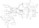
図1は、本発明の第一の実施形態における光干渉断層撮像法を用いた撮像装置(OCT装置)の構成例の概略を示す模式図である。該OCT装置は、光源部10、干渉部20、検出部30、情報取得部40、測定アーム50及び参照アーム60を有する。光源部10から射出される光は、その周波数が掃引される。干渉部20では、後述する反射光と参照光とより干渉光を生成する。検出部30では、この干渉光を検出する。情報取得部40は、検出された干渉光に基づいて、被検眼100の眼底の情報を取得する。
[First Embodiment]
FIG. 1 is a schematic view showing an outline of a configuration example of an imaging device (OCT device) using the optical coherence tomography imaging method according to the first embodiment of the present invention. The OCT device includes a
干渉部20及び測定アーム50について説明する。干渉部20は、カプラ21及びカプラ22を有している。光源部10、カプラ21及び測定アーム50は光ファイバーにより接続される。測定アーム50は、カプラ21側より順に配置されたコリメータレンズ52、X軸スキャナー53、Y軸スキャナー54、及びフォーカスレンズ55を有する。
The
まず、カプラ21は、光源部10から射出された光を眼底へ照射する照射光と参照光とに分岐する。照射光は、測定アーム50を経由して被検眼100に照射される。より具体的には、測定アーム50に入射した照射光は、コリメータレンズ52から空間光として射出される。その後、照射光は、X軸スキャナー53、Y軸スキャナー54、及びフォーカスレンズ55を介して被検体100の眼底に照射される。なお、X軸スキャナー53及びY軸スキャナー54は眼底を照射光で走査する機能を有する走査部である。該走査部によって、照射光の眼底への照射位置が変えられる。そして、眼底からの後方散乱光(反射光)は、再びフォーカスレンズ55、Y軸スキャナー54、X軸スキャナー53、及びコリメータレンズ52を経由して測定アーム50から射出される。射出された反射光は、カプラ21を経由してカプラ22に入射する。
First, the
参照アーム60について説明する。参照アーム60は光ファイバーを介してカプラ21と接続される。参照アーム60は、該カプラ21側より順に配置されたコリメータレンズ62、分散補償ガラス63、光路調整光学系64、分散調整プリズムペア65及びコリメータレンズ66を有する。
The
参照光は光ファイバーを通じて参照アーム60に至り、参照アーム60を経由してカプラ22に入射する。より具体的には、参照アーム60に入射した参照光は、偏光コントローラ61で偏光状態を整えられた後、コリメータ62から空間光として射出される。その後、参照光は分散補償ガラス63を経て光路長調整光学系64に至る。光路調整光学系64は、図中矢印方向に移動することにより参照光の光路長を調整する。光路調整光学系64を経た参照光は分散調整プリズムペア65を通り、コリメータレンズ66を介して光ファイバーに入射される。該光ファイバーはカプラ22に接続されており、参照アーム60から射出された参照光はカプラ22に入射する。
The reference light reaches the
カプラ22で測定アーム50を経由した被検体100の反射光と参照アーム60を通った光とが合波され干渉光が生成される。そして、その干渉光を検出部30で検出する。検出部30は、差動検出器31、位相差発生部33、及びアナログデジタル変換部であるA/D変換器32a及びA/D変換器32bを有している。
The
検出部30では、カプラ22で干渉光を発生させた後すぐに分波された干渉光の各々を差動検出器31で検出する。そして、差動検出器31で為される光電変換により電気信号に変換されたアナログ信号である干渉信号を再度分岐させ、A/D変換器32a及びA/D変換器32bで各々デジタル信号に変換している。A/D変換器32a及び32bによるサンプリングは、内部クロックを用いて等時間間隔に行われる。内部クロックは、A/D変換器32a及び32bの各々に備えられている。
In the
差動検出器31とA/D変換器32bとの間には、A/D変換器32a及び32bの各々が取得する干渉信号に対して位相差を与えるための位相差発生部33が配置されている。該位相差発生部33は同軸ケーブルであり、これが配置されることによってA/D変換器32aとA/D変換器32bとは異なる時刻でアナログ信号である干渉信号のアナログデジタル変換を行うこととなる。各々の変換器より得られたデジタル信号は、情報取得部40に送られる。情報取得部40においてこれらデジタル信号に対してフーリエ変換などの周波数分析が行われることで、眼底の情報が得られる。得られた眼底の情報は、表示部70によって断層像として表示される。
A
なお、以上は、被検眼100のある1点における断層に関する情報の取得のプロセスであり、このように被検眼100の奥行き方向の断層に関する情報を取得することをA−scanと呼ぶ。また、A−scanと直交する方向で被検眼100の断層に関する情報、即ち被検眼100の奥行き方向の2次元画像を取得することをB−scanと呼ぶ。更に、A−scan及びB−scanのいずれの走査方向とも直交する方向で情報を取得することをC−scanと呼ぶ。換言すれば、3次元断層像を取得する際に眼底面内に2次元ラスター走査する場合、高速な走査方向がB−scanであり、更にB−scanをその直交方向に並べて走査する低速な走査方向をC−scanとなる。A−scan及びB−scanを行うことで2次元の断層像が得られ、A−scan、B−scan及びC−scanを行うことで、3次元の断層像を得ることができる。B−scan及びC−scanは、上述したX軸スキャナー53及びY軸スキャナー54に照射光の照射位置を走査することより行われる。
The above is the process of acquiring information on the tomography at one point of the
なお、X軸スキャナー53及びY軸スキャナー54は、それぞれ回転軸が互いに直交するよう配置された偏向ミラーで構成されている。X軸スキャナー53はX軸方向の走査を行い、Y軸スキャナー54はY軸方向の走査を行う。ここでX軸方向及びY軸方向の各方向は、被検眼100の眼球の眼軸方向に対して垂直な方向で、互いに垂直な方向である。また、B−scan及びC−scanのようなライン走査方向と、X軸方向又はY軸方向とは、一致していなくてもよい。このため、B−scan及びC−scanのライン走査方向は、撮像したい2次元の断層像あるいは3次元の断層像に応じて、適宜決めることができる。
The
また、本実施形態では、X軸スキャナー53とY軸スキャナー54とをともに駆動させ、偏向ミラーの角度を変えることでさまざまな照射光の走査が可能である。例えば、図2(a)及び(b)に示すようなラスター走査でもよいし、図2(c)に示すような眼球の一点(例えば黄班)を複数回通過する方法でもよい。また、図2(d)に示すような眼球の一点(例えば黄班)を中心としてらせん状に照射光の走査を行ってもよい。
Further, in the present embodiment, various irradiation lights can be scanned by driving both the
ところで、眼底検査においては、黄班と視神経乳頭とを同一の、つまりは一回の走査で撮像したいという要望がある。これを実現するために求められるOCT装置の照射光で走査する範囲(走査角度)について、図3を用いて説明する。図3は、眼球を球体として仮定したときの模式図である。眼球の瞳孔中心の反対側には黄班がある。また、黄班から少し離れた位置に視神経乳頭がある。この黄班と視神経乳頭は、眼底において特に重要な部位である。 By the way, in fundus examination, there is a desire to image the macula and the optic nerve head in the same manner, that is, in one scan. The range (scanning angle) to be scanned by the irradiation light of the OCT apparatus required to realize this will be described with reference to FIG. FIG. 3 is a schematic view assuming that the eyeball is a sphere. There is a macula on the opposite side of the center of the pupil of the eyeball. In addition, the optic disc is located slightly away from the macula. The macula and optic disc are particularly important sites in the fundus.
標準的な成人の眼底では、黄班と視神経乳頭を包含する距離Dは約5.75mmである。照射光は被検眼100の瞳孔より内部に照射され、眼球の瞳孔中心を中心に旋回されて眼底を走査する。黄班を中心として視神経乳頭を包含する範囲を同じ走査で一度に撮像する場合、個人差も勘案すると、黄班と視神経乳頭を結ぶ最短の曲線の長さ(撮像範囲)Lが14mm程度必要である。
In a standard adult fundus, the distance D including the macula and the optic disc is about 5.75 mm. The irradiation light is emitted inside from the pupil of the
ここで、この撮像範囲に対応する瞳孔中心を中心に旋回される照射光(測定光)の振れ角をαとする。成人の眼球の直径の平均は24mm程度なので、撮像範囲Lを14mm以上にするためには、振れ角αは33.4度以上必要になる。この角度は、眼球内の平均屈折率が1.38であることを利用して、空気中の、瞳孔中心に入射する照射光の振れ角βで表すと、arcsin(1.38×sin(33.4度/2))×2≒47度となる。 Here, let α be the deflection angle of the irradiation light (measurement light) swirled around the center of the pupil corresponding to this imaging range. Since the average diameter of an adult eyeball is about 24 mm, a swing angle α of 33.4 degrees or more is required to make the imaging range L 14 mm or more. This angle is expressed by the deflection angle β of the irradiation light incident on the center of the pupil in the air by utilizing the fact that the average refractive index in the eyeball is 1.38, arcsin (1.38 × sin (33)). .4 degrees / 2)) × 2 ≒ 47 degrees.
つまり、黄班を中心に配置させた状態で、黄班と視神経乳頭とを同時に撮像するために眼底を照射光で線状に走査する場合には、眼底を走査する角度範囲が空気中で換算して47度以上であればよい。なお、以下では、眼底を照射光で線状に走査する場合における眼底を走査する角度範囲を空気中で換算した範囲を画角とする。つまり、振れ角βを画角とする。 In other words, when the fundus is linearly scanned with irradiation light in order to simultaneously image the macula and the optic nerve head with the macula centered, the angle range for scanning the fundus is converted in the air. It may be 47 degrees or more. In the following, the angle of view is the range obtained by converting the angle range for scanning the fundus in the air when the fundus is linearly scanned with the irradiation light. That is, the swing angle β is the angle of view.
次に、上記の振れ角βで走査する場合に生じる課題について、図4を用いて説明する。図4は、図3と同様に眼球を球体として仮定したときの模式図である。図4の破線は、照射光の走査軌跡を表している。図4で示すように、瞳孔中心から眼球の外壁つまり眼底までの物理的な距離は、黄班ではa+bであり、黄班から離れた位置にある部分(角度θ/2の部分)ではaである。a及びbは眼軸長の長さTと眼球内の振れ角θを用いると、各々以下の式で表される。
a=T×cos(θ/2) ・・・式1
a+b=T ・・・式2
Next, the problem that occurs when scanning at the above-mentioned runout angle β will be described with reference to FIG. FIG. 4 is a schematic view when the eyeball is assumed to be a sphere as in FIG. The broken line in FIG. 4 represents the scanning locus of the irradiation light. As shown in FIG. 4, the physical distance from the center of the pupil to the outer wall of the eyeball, that is, the fundus is a + b in the macula, and a in the portion away from the macula (angle θ / 2). is there. a and b are expressed by the following equations using the length T of the axial length and the swing angle θ in the eyeball, respectively.
a = T × cos (θ / 2) ・ ・ ・
a + b = T ・ ・ ・
このように、瞳孔中心から黄班までの距離と瞳孔中心から黄班から離れた位置までの距離とは、距離bだけ異なる。このbは角度θが大きくなればなるほど、大きくなる。従って、広画角の眼底検査用のOCT装置では、瞳孔中心から黄班までの光路長と瞳孔中心から黄班から離れた周辺の位置までの距離とが大きく異なってしまう。成人の眼軸長Tは個人差が大きく、95%の人が含まれる眼軸長Tの範囲は21mm以上28mm以下である。ここでは、眼軸長Tの値として、その範囲の最大値である28mmを用い、眼球内の振れ角θが33.4度の場合、式1、2からbは約1.2mmとなる。
As described above, the distance from the center of the pupil to the macula and the distance from the center of the pupil to the position away from the macula differ by the distance b. This b becomes larger as the angle θ becomes larger. Therefore, in the OCT device for fundus examination with a wide angle of view, the optical path length from the center of the pupil to the macula and the distance from the center of the pupil to the peripheral position away from the macula are significantly different. The axial length T of an adult varies greatly among individuals, and the range of the axial length T including 95% of people is 21 mm or more and 28 mm or less. Here, 28 mm, which is the maximum value in the range, is used as the value of the axial length T, and when the swing angle θ in the eyeball is 33.4 degrees,
また、眼底検査用のOCT装置で観察する眼底組織は、眼底の表面近傍の網膜とその奥にある脈絡膜である。網膜は最厚部分で0.50mm、脈絡膜は0.30mm程度であるので、眼底検査用のOCT装置は少なくとも0.80mmの深さまで撮像する必要がある。つまり、眼底の表面と脈絡膜との間では、0.80mmの距離の差が生じる。 The fundus tissue observed by the OCT device for fundus examination is the retina near the surface of the fundus and the choroid behind it. Since the thickest part of the retina is about 0.50 mm and the choroid is about 0.30 mm, it is necessary for the OCT device for fundus examination to image to a depth of at least 0.80 mm. That is, there is a distance difference of 0.80 mm between the surface of the fundus and the choroid.
よって、黄班と視神経乳頭とを同一の走査で撮像し、かつ視神経乳頭の表面近傍と黄班
の奥にある脈絡膜との情報を得るためには、次のような条件のデータサンプリングが求められる。すなわち、2×(b+0.80)≒4.0mmの距離差が生じても、折り返しのない断層像を得ることが求められる。この距離差は、空気中の光路差で考えると、4.0mm×1.38≒5.5mmに対応する。つまり、画角47度以上としても、精度よく断層情報を得ることができるOCT装置を実現するためには、空気中で5.5mmの光路長差があるときにも折り返しのない断層像を得るような高速なデータサンプリングを等波数間隔で行うことが求められる。
Therefore, in order to image the macula and the optic nerve head with the same scan and obtain information on the choroid near the surface of the optic nerve head and behind the macula, data sampling under the following conditions is required. .. That is, it is required to obtain a tomographic image without folding back even if a distance difference of 2 × (b + 0.80) ≈4.0 mm occurs. This distance difference corresponds to 4.0 mm × 1.38 ≈ 5.5 mm in terms of the optical path difference in the air. That is, in order to realize an OCT device capable of accurately obtaining tomographic information even when the angle of view is 47 degrees or more, a tomographic image without folding back is obtained even when there is an optical path length difference of 5.5 mm in the air. It is required to perform such high-speed data sampling at equal wavenumber intervals.
広画角に眼底を撮像する場合、画角が広くなるので断層像の撮像点数も多くする必要がある。この撮像点数を多くするためには、A−scanを高速に行う必要がある。A−scanレートfaとA/D変換器のサンプリングレートfsの関係は、1A−scanあたりのサンプリングデータ数Na、光源の1A−scanにおける波長掃引時間の割合d、光源中心波長λc、光源掃引波長帯域Δλ、断層像の撮像深さ範囲Δzを用いると、下記式で表される。

例えば、掃引周波数100kHz、波長掃引時間率50%、中心波長1060nm、掃引波長帯域110nm、の波長掃引光源を用いて、撮像深さ5.5mmの断層像を実現するためには、波長掃引の歪量±20%の場合、サンプリングの周波数は約500MHzと導出される。このため、A/D変換器は、約500MHz以上の周波数でA/D変換(サンプリング)可能であることが求められる。また、さらに眼底撮像の広画角化とA−scanの高速化のためには、A−scanレートの増加に比例して、サンプリングレートを高速化しなければならない。そして、高速サンプリングができる高価なA/D変換器を使う必要が生じる。また、単純に複数のA/D変換器を用いてもサンプリングデータが等波数間隔とはならず、良好な断層像を得ることが難しい。本実施形態はこのことを勘案し、複数のA/D変換器を用いて干渉信号のデータサンプリングを行い、各A/D変換器のサンプリングデータを等波数間隔のデータとして統合して、周波数解析を行う事によって良好な眼底の断層像を得ている。
ここで、上述した中心波長、波長幅、撮像深さ等と略同じ値で、波長掃引光源のA−scanレートが約300kHz以上の場合、サンプリングの周波数は約1.0GHz以上と導出される。このとき、A/D変換器がA/D変換(サンプリング)可能な周波数との差分が顕著になり、本実施形態の適用がより好ましい状況となる。すなわち、本実施形態は、光源部が射出する光の周波数の掃引する速度である波長掃引光源のA−scanレートが約300kHz以上の場合に適用されることが好ましい。また、換言すると、本実施形態は、A/D変換器がサンプリングする必要のある周波数が約1.0GHz以上である場合に適用されることが好ましい。
For example, in order to realize a tomographic image with an imaging depth of 5.5 mm using a wavelength sweep light source having a sweep frequency of 100 kHz, a wavelength sweep time rate of 50%, a center wavelength of 1060 nm, and a sweep wavelength band of 110 nm, wavelength sweep distortion is required. When the amount is ± 20%, the sampling frequency is derived as about 500 MHz. Therefore, the A / D converter is required to be capable of A / D conversion (sampling) at a frequency of about 500 MHz or higher. Further, in order to further widen the angle of view of fundus imaging and increase the speed of A-scan, the sampling rate must be increased in proportion to the increase of the A-scan rate. Then, it becomes necessary to use an expensive A / D converter capable of high-speed sampling. Further, even if a plurality of A / D converters are simply used, the sampling data does not have equal wavenumber intervals, and it is difficult to obtain a good tomographic image. In this embodiment, in consideration of this, data sampling of the interference signal is performed using a plurality of A / D converters, and the sampling data of each A / D converter is integrated as data of equal wave number intervals to perform frequency analysis. A good tomographic image of the fundus is obtained by performing.
Here, when the A-scan rate of the wavelength sweep light source is about 300 kHz or more with substantially the same values as the above-mentioned center wavelength, wavelength width, imaging depth, etc., the sampling frequency is derived to be about 1.0 GHz or more. At this time, the difference from the frequency at which the A / D converter can perform A / D conversion (sampling) becomes remarkable, and the application of this embodiment becomes more preferable. That is, this embodiment is preferably applied when the A-scan rate of the wavelength sweep light source, which is the speed at which the frequency of the light emitted by the light source unit is swept, is about 300 kHz or more. In other words, the present embodiment is preferably applied when the frequency that the A / D converter needs to sample is about 1.0 GHz or more.
以下、本発明の第一の実施形態において実行される処理内容について説明する。図5は、被検眼の断層像を生成するまで処理の全体フローを示している。本実施形態では、断層画像の生成において、事前処理である処理210と本測定処理である処理220とを有している。
Hereinafter, the processing content executed in the first embodiment of the present invention will be described. FIG. 5 shows the overall flow of processing until a tomographic image of the eye to be inspected is generated. In the present embodiment, in the generation of the tomographic image, there is a
より詳細には、処理210には、補正用干渉光の検出の処理211、データ関連付けの処理212、そしてリスケーリングマップを作成する処理213が含まれる。まず、処理211において、情報取得部40が、検出部30から送られた補正用干渉光のデジタル信号を受け取る。補正用干渉光には、例えばミラーを用いて得られる干渉光が用いられる。次に、処理212において、A/D変換器32a及び32bが取得した各々のデジタル信号のデータ配列を統合するために、情報取得部40が各データ配列のインデックスを関連付ける処理を行う。処理212については、図6を用いて後述する。
More specifically, the
最後に、処理213において、情報取得部40が、デジタル信号を等波数間隔のデータセットに変換するために用いるリスケーリングマップを作成する。なお、このリスケーリングマップの作成等の事前処理210はOCT装置の起動時に行う、或いは例えば一定期間経過後に行われるOCT装置のメンテナンス時に行うこととし、通常は不図示の記憶部に記憶しておけば良い。本測定時には、当該リスケーリングマップを適宜読み出してこれを用いれば良い。
Finally, in
本測定である処理220では、被検眼100の断層像の生成を行う。まず、処理221において、検出部30が被検眼100を撮像対象とした干渉信号を検出する。次に、処理222において、情報取得部40が、データ配列の統合、等波数間隔データ配列への変換、そしてフーリエ変換などの周波数分析を用いて被検眼100の断層像を生成する。
In the
ここで前述した処理212に関して、図6を用いて詳細に説明する。この処理では、A/D変換器32a及び32bがサンプリングした干渉信号について、各データ配列のインデックスi及びjを関連付けるための関連付けテーブルi’(j)を作成する。まず、情報取得部40が、処理311において、A/D変換器32a及びA/D変換器32b各々がサンプリングしたデジタル信号データ配列Ipre1(i)及びIpre2(j)を取得する。
Here, the
次に、処理312において、干渉信号のデータ配列Ipre1(i)及びIpre2(j)から各データの位相情報Φpre1(i)及びΦpre2(j)を抽出する。具体的には、ヒルベルト変換を用いて位相抽出してから位相接続を行うことで、Φpre1(i)及びΦpre2(j)を単調増加する単一の位相データ配列として得る。
Next, in the
このとき、正確な位相接続をするために、連続する2つのサンプリングデータΦ(i)及びΦ(i+1)の位相差が2π未満であることが望ましい。そのためには、検出部30のサンプリング周波数fsが干渉信号の周波数fよりも高い必要がある。即ち、事前処理において検出部39が検出する補正用干渉信号の周波数は、検出部30が実際に検出する際の検出周波数よりも低く設定されなければならない。
At this time, in order to make an accurate phase connection, it is desirable that the phase difference between two consecutive sampling data Φ (i) and Φ (i + 1) is less than 2π. For that purpose, the sampling frequency fs of the
なお、ここで干渉信号の周波数fとは、A/D変換器32a及び32bがそれぞれ検出する干渉スペクトルの時間変化のことである。そのため、測定アーム50と参照アーム60との光路長差ΔZが以下の式を満たす位置に被検眼100の代わりにミラーを配置して所望の周波数の干渉信号を生成する。
そして、処理313において抽出した位相データ配列Φpre1(i)を用いてフィッティング関数Φpre’1(i)を作成する。最後に、処理314において、A/D変換器32bのj番目のサンプリングデータの位相Φpre2(j)がΦpre2(j)=Φpre’1(i’)となるフィッティング関数上のデータ番号i’を算出する。そして、算出結果を、インデックスiとインデックスjとの関連付けテーブルi’(j)として情報取得部40に記憶する。以上で、A/D変換器32a及び32bがサンプリングしたデータ配列のインデックスの関連付けテーブルの作成を終了する。
Then, the fitting function Φpre'1 (i) is created by using the phase data array Φpre1 (i) extracted in the
次に、図5に示す処理213について説明する。処理213では、リスケーリングマップの作成を行う。リスケーリングマップとは、等波数間隔のデータ配列Ipre1(i”)となるようなデータ配列i”(k)であり。A/D変換器32aが取得した干渉信号のデータ配列Ipre1(i)をもとにi”(k)を算出する。まず、処理312において取得したA/D変換器32aのデジタル信号の位相情報Φpre1(i)を読み出す。次に、下記式で表されるi”(k)をリスケーリングマップとして取得する。
ただし、ΔΦは干渉信号を等波数間隔でリサンプリングする際の連続するデータ間の位相差、Φmaxは位相データ配列の最大値、k=0〜N3−1であり、N3はリサンプリングするデータ点数である。以上でリスケーリングマップの取得が終了する。 However, ΔΦ is the phase difference between continuous data when resampling the interference signal at equal wave number intervals, Φmax is the maximum value of the phase data array, k = 0 to N3-1, and N3 is the number of data points to be resampled. Is. This completes the acquisition of the rescaling map.
以上が事前処理210の内容になる。次に、実際に断層像を生成する本測定処理である処理220の詳細について説明する。
The above is the content of the
図7は、処理220における断層画像の生成処理である処理222の内容を示している。まず、処理510において、情報取得部40が、処理221で検出部30が各々のA/D変換器を通じて検出したデジタル干渉信号I1(i)及びI2(j)を取得する。ただし、i=0〜N1−1、j=0〜N2−1である。このとき、測定アーム50の射出先には実際に断層像を撮像する被検眼100が配置されている。次に、処理511において、A/D変換器32bが取得したデジタル信号I2(j)のデータ番号の振り直しを行う。処理212において作成したインデックスの関連付けテーブルi’(j)を用いて、I’2(i’(j))=I2(j)となるデータ配列を作成する。
FIG. 7 shows the contents of the
次に、処理512において、A/D変換器32aが取得した干渉信号データI1(i)とデータ番号を振り直したA/D変換器32bの取得データI’2(i’(j))とを統合したデータ配列I(t)を作成する。
Next, in the
そして、処理513において、FPN(Fixed patern noise)除去を行う。FPN除去では、例えば、被検眼100からの戻り光がない状態で取得したスペクトルデータを、干渉信号I(t)から減算してI’(t)を得る(t=0、N1+N2−1)。該スペクトルデータは、具体的には、フォーカスレンズ55と被検眼100との間に障害物を配置するなどして、被検眼100への測定光の射出を遮った状態で得る。
Then, in the
FPN除去後、処理514において、リスケーリング処理を行い、等波数間隔のデータ配列I’(k)を取得する。より具体的には、まず、処理513で求めたFPN除去後のデジタル信号I’(t)におけるi”(k)番目の数値を、既知の数値から1Dもしくはスプライン補間等を用いて算出する。リスケーリング処理の補間精度を向上のために、補間計算の前に、干渉信号データI(t)に対して、FFT、ゼロパディング、そして逆FFTを順に行うことも可能である。
After removing the FPN, in the
最後に、処理515として、I’(k)にFFTをかけて断層像を取得する。処理515の前後に、数学的な補償処理や画像補正が行われてもよい。以上の処理を経ることにより、二つのA/D変換器を用いて被検眼100より得た二つのデータ配列を合成して、単一のデータ配列I(t)を得ることができる。これにより、単一のA/D変換器を用いた場合に比べて多くの撮像点数を有したA−scanを行うことが可能となる。
Finally, as
即ち、以上の実施形態によれば、複数のA/D変換器を用いることでより高速サンプリングが可能となる。また、干渉信号の位相情報を用いて、各A/D変換器のサンプリングデータのインデックス関連付けとリスケーリング処理を行うことによって等波数間隔のデータセットを生成することが可能となる。結果、高いA−scanレートで良好な断層像を得ることができ、1回の走査の撮像範囲を大きくしても断層に関する情報を精度よく取得することが可能となる。 That is, according to the above embodiment, higher speed sampling is possible by using a plurality of A / D converters. Further, by using the phase information of the interference signal to perform index association and rescaling processing of the sampling data of each A / D converter, it is possible to generate a data set having equal wavenumber intervals. As a result, a good tomographic image can be obtained at a high A-scan rate, and information on the tomographic image can be accurately acquired even if the imaging range of one scan is increased.
なお、以上に述べた処理212は、情報取得部40内に包含される、少なくとも二つのデータセット各々のインデックスの関連付けを行うデータ関連付け手段により実行される。このインデックスの関連付けに際しては、該データ関連付け手段によってデータセット各々の位相情報を取得し、この位相情報に基づいて該インデックスの関連付けが行われる。なお、本実施形態において、この位相情報はデータセット各々をヒルベルト変換し、この変換後のデータセットより求めている。処理222、より詳細には処理512は、情報取得部40内に包含される、関連付けられたインデックスに基づいて、或いは取得された位相情報に基づいて少なくとも二つのデータセットを統合する統合手段により実行される。処理514におけるリスケーリング処理は、情報取得部40内に包含される、統合されたデータセットを等波数間隔のデータセットに変換するリスケーリング手段により実行される。更に、処理222における画像の生成は、情報取得部40内に包含される、統合されたデータセットに基づいて被検眼の断層像を生成する画像生成手段により実行される。
The
[第二の実施形態]
図8は、本発明の第二の実施形態における光干渉断層撮像法を用いた撮像装置(OCT装置)の構成例の概略を示す模式図である。なお、第一の実施形態と同一の構成要素については、例えば光源部710、干渉部720、検出部730、情報取得部740、測定アーム750、及び参照アーム760のように同一の名称を用いることによりここでの詳細に説明を省略する。
[Second Embodiment]
FIG. 8 is a schematic diagram showing an outline of a configuration example of an imaging device (OCT device) using the optical coherence tomography imaging method according to the second embodiment of the present invention. For the same components as in the first embodiment, the same names are used, for example, the
本第二の実施形態は、第一の実施形態に対して、kクロック発生部780を備える点において異なっている。該kクロック発生部780を配することによって、A/D変換器732aが等波数間隔でのサンプリングを行うこととなる。本実施形態では、A/D変換器732aが等波数間隔サンプリングを行うため、サンプリングデータにおいて線形に位相が増加するデータセットとなる。そのため、後述する位相情報を用いたフィッティング処理において、高次のフィッティングをする必要がなく、リスケーリングマップを作成する必要がなくなることから、計算負荷を低減することができる。
The second embodiment is different from the first embodiment in that it includes a k-
本実施形態に係るOCT装置は、光源部710、干渉部720、検出部730、情報取得部740、測定アーム750及び参照アーム760を有する。射出される光周波数が掃引される光源部710と、干渉光を生成する干渉部720と、干渉光を検出する検出部730と、干渉光に基づいて、被検体100の眼底の情報を取得する情報取得部740と、を有している。さらに、OCT装置は、測定アーム750と参照アーム760を有している。
The OCT apparatus according to the present embodiment includes a
カプラ722で測定アーム750を経由した被検体100の反射光と参照アーム760を通った光とが合成された干渉光が生成される。そして、その干渉光を検出部730で検出する。検出部730は、差動検出器731とアナログデジタル変換部であるA/D変換器732a及びA/D変換器732bを有している。検出部730では、カプラ722で干渉光を発生させた後すぐに分波された干渉光の各々を差動検出器731で検出する。そして、差動検出器731で電気信号に変換された干渉信号を再度分岐させ、A/D変換器732a及びA/D変換器732bで各々デジタル信号に変換している。
Interference light is generated by combining the reflected light of the subject 100 that has passed through the
図8のOCT装置において、A/D変換器732aの干渉信号のサンプリングタイミングは、光源部710の外に設けられるkクロック発生部780が発信するkクロック信号に基づいて等光周波数(等波数)間隔に行われる。一方、A/D変換器732bのサンプリングタイミングは、A/D変換器に備えられた内部クロックによって等時間間隔で行われる。光源部710から射出された光の一部をkクロック発生部780に分岐するために、カプラ790が設けられている。なお、kクロック発生部780、及びカプラ790は光源部710に組み込まれていてもよい。
In the OCT apparatus of FIG. 8, the sampling timing of the interference signal of the A /
A/D変換器各々によりサンプリングされたデジタル信号は、情報取得部740に送られる。情報取得部740においてこれらデジタル信号に対してフーリエ変換などの周波数分析が行われることで、眼底の情報が得られる。得られた眼底の情報は、表示部770によって断層像として表示される。
The digital signal sampled by each of the A / D converters is sent to the
以下、本発明の第二の実施形態において実行される処理内容について説明する。図9は、被検眼の断層像を生成までの処理の全体フローを示している。本実施形態では、断層画像の生成において、事前処理である処理810と本測定処理である処理820とを有している。
Hereinafter, the processing content executed in the second embodiment of the present invention will be described. FIG. 9 shows the overall flow of processing until the tomographic image of the eye to be inspected is generated. In the present embodiment, in the generation of the tomographic image, the
より詳細には、処理810には、補正用干渉光の検出の処理811、及び各A/D変換器がサンプリングしたデータ配列のインデックスを関連付ける処理812が含まれる。まず、処理811において、検出部730が処理812で用いる補正用干渉信号を検出する。該補正用干渉信号を得るための補正用干渉光には、例えばミラーを用いて得られる干渉光が用いられる。次に、処理812において、A/D変換器732a及び732b各々がサンプリングした離散的な干渉信号のデータ配列を統合するために、情報取得部740が各々のデータ配列のインデックスを関連付ける処理を行う。
More specifically, the
画像生成処理である本測定処理820は、干渉信号の検出の処理821と断層像の生成のための処理822とを有する。該処理820では、被検眼100を撮像対象として干渉信号の取得からOCT画像の生成までを行う。まず、処理821において、検出部730が被検眼100を撮像対象とした場合の干渉信号を検出する。次に、処理822において、情報取得部740が、事前処理により得たインデックスの関連付けの結果を用いたデータ配列の統合、等波数間隔データ配列への変換、そしてフーリエ変換などの周波数分析を用いて被検眼100のOCT画像を生成する。
The
なお、前述した処理812は、第一の実施例形態における処理212と同様であり、図6で示される。この処理では、A/D変換器732a及び732bがサンプリングした干渉信号について、各データ配列のインデックスi及びjを関連付けるための関連付けテーブルi’(j)を作成する。まず、情報取得部740が、処理811において、A/D変換器732aがサンプリングした離散的な干渉信号データ配列Ipre1(i)を取得する。一方、処理311において、A/D変換器732bは、kクロック信号に対応するA/D変換器732aとは異なる時刻にサンプリングした干渉信号のデータ配列Ipre2(j)を取得する。
The above-mentioned
次に、処理312において干渉信号のデータ配列Ipre1(i)及びIpre2(j)から各データの位相情報Φpre1(i)及びΦpre2(j)を抽出する。具体的には、ヒルベルト変換を用いて位相抽出してから位相接続を行うことで、Φpre1(i)及びΦpre2(j)を単調増加する単一の位相データ配列として得る。
Next, in the
そして、処理313において抽出した位相データ配列Φpre1(i)を用いてフィッティング関数Φ’pre1(i)を作成する。このとき、A/D変換器732aはkクロック発生部780から発せられたkクロック信号を用いて等波数間隔で行われるため、フィッティング関数Φ’pre1(i)は略線形になる。
Then, the fitting function Φ'pre1 (i) is created by using the phase data array Φpre1 (i) extracted in the
最後に、処理314において、A/D変換器732bのj番目のサンプリングデータの位相Φpre2(j)がΦpre2(j)=Φ’pre1(i’)となるフィッティング関数上のデータ番号i’を算出する。そして、算出結果を、インデックスiとインデックスjとの関連付けテーブルi’(j)として、情報取得部740に記憶する。以上で、A/D変換器732a及び732bがサンプリングした干渉信号に関するデータ配列のインデックス関連付けテーブルの作成を終了する。
Finally, in the
本測定のための処理820は、第一の実施形態における処理220と同様であり、断層像の生成のための処理822の詳細は図7で示される。詳細については第一の実施形態の場合と同様であるため、ここでの説明は省略する。
The
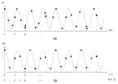
なお、図10は、第二の実施形態における処理514の内容を説明するための概念図である。図10(a)は処理512において統合された干渉信号I(t)(t=0、N1+N2−1)、図10(b)は処理514のリスケーリング処理後の干渉信号I’(k)を示している。横軸は第1のA/D変換器732aのデータ番号、縦軸は干渉信号強度、黒丸は第1のA/D変換器732aのサンプリング点、白丸は第2のA/D変換器732bのサンプリング点、波線は説明のために簡素化した単一周期の干渉信号を表す余弦波である。
Note that FIG. 10 is a conceptual diagram for explaining the contents of the
実際の処理においては、まず、リスケーリング処理後のデータ数N3を決める。一例として、図10(b)では、データ数N3=2×N1であり、サンプリング間隔はΔt=0.5である。次に、図10(b)中の白丸の数値を算出する。より具体的には、(a)中の白丸および黒丸の既存点から1Dもしくはスプライン補間等を用いて算出する。リスケーリング処理の補間精度を向上のために、補間計算の前に、干渉信号データI(t)に対して、FFT、ゼロパディング、そして逆FFTを順に行うことも可能である。 In the actual processing, first, the number of data N3 after the rescaling processing is determined. As an example, in FIG. 10B, the number of data is N3 = 2 × N1, and the sampling interval is Δt = 0.5. Next, the numerical values of the white circles in FIG. 10B are calculated. More specifically, it is calculated from the existing points of the white circle and the black circle in (a) by using 1D or spline interpolation or the like. In order to improve the interpolation accuracy of the rescaling process, it is possible to perform FFT, zero padding, and inverse FFT in order on the interference signal data I (t) before the interpolation calculation.
以上の処理を行うことによって、リスケーリングマップを作成することなく、別々のA/D変換器より得たデータ配列を統合することが可能となる。これにより、高速サンプリングが可能となり、高いA−scanレートで良好な断層像を得ることができ、1回の走査の撮像範囲を大きくしても断層に関する情報を精度よく取得することが可能となる。 By performing the above processing, it is possible to integrate the data sequences obtained from different A / D converters without creating a rescaling map. As a result, high-speed sampling becomes possible, a good tomographic image can be obtained at a high A-scan rate, and information on the tomographic image can be accurately acquired even if the imaging range of one scan is increased. ..
なお、以上の実施形態では、A/D変換器(アナログデジタル変換器)は二つ用いることとしているが、これ以上であっても良い。また、A/D変換器の数を増やした場合、各々の位相をずらすように複数の位相差発生手段を配することが好ましい。検出部に含まれる位相差発生手段は、データセットの各々に対して位相差を与え、該位相差はデータセット各々におけるインデックスの相違を与える。或いは第二の実施形態の場合、少なくとも二つのA/D変換器の内の少なくとも一つのA/D変換器より得られるデータセットを等波数間隔とするようにkクロック発生部を配すると良い。またこの場合、少なくとも二つのA/D変換器の内の他のA/D変換器は等時間間隔のデータセットを供給することが好ましい。 In the above embodiment, two A / D converters (analog-digital converters) are used, but more than this may be used. Further, when the number of A / D converters is increased, it is preferable to arrange a plurality of phase difference generating means so as to shift each phase. The phase difference generating means included in the detection unit gives a phase difference to each of the data sets, and the phase difference gives an index difference in each of the data sets. Alternatively, in the case of the second embodiment, the k-clock generator may be arranged so that the data set obtained from at least one A / D converter among at least two A / D converters has an equal wavenumber interval. Further, in this case, it is preferable that the other A / D converter among at least two A / D converters supplies the data set at equal time intervals.
(その他の実施例)
なお、本発明は上述した実施形態に限定されるものではなく、本発明の趣旨を逸脱しない範囲内において、種々の変形、変更を行って実施することができる。例えば、上記実施形態では、本発明の適用対象として撮像装置及び該撮像装置を作動させる方法を例示している。しかし、光学系、干渉部、A/D変換器等からなる撮像装置と通信可能に接続されて、データセットの生成や統合を行って画像生成を為す情報処理装置或いはその作動方法の態様とすることも可能である。更に、上記実施形態では、被検査物が被検眼眼底の場合について述べているが、眼以外の皮膚や臓器等の被測定物に本発明を適用することも可能である。この場合、本発明は眼科装置以外の、例えば内視鏡等の医療機器としての態様を有する。従って、本発明は眼科装置に例示される検査装置を対象とした撮像装置として把握され、被検眼は被検査物の一態様として把握されることが望ましい。
(Other Examples)
The present invention is not limited to the above-described embodiment, and can be modified and modified in various ways without departing from the spirit of the present invention. For example, in the above embodiment, the image pickup device and the method of operating the image pickup device are exemplified as the application target of the present invention. However, it is an information processing device or an operation method thereof that is communicably connected to an image pickup device including an optical system, an interference unit, an A / D converter, etc., and generates or integrates a data set to generate an image. It is also possible. Further, in the above embodiment, the case where the object to be inspected is the fundus of the eye to be inspected is described, but the present invention can also be applied to the object to be inspected such as skin and organs other than the eye. In this case, the present invention has an aspect as a medical device other than an ophthalmic device, for example, an endoscope. Therefore, it is desirable that the present invention is grasped as an imaging device for an inspection device exemplified by an ophthalmic device, and the eye to be inspected is grasped as an aspect of an object to be inspected.
また、本発明は、上述した実施形態の機能(例えば、上記の各部の処理を各工程に対応させたフローチャートにより示される処理)を実現するソフトウェアのプログラムコードを記録した記憶媒体を、システム或いは装置に供給することによっても実現できる。この場合、そのシステム或いは装置のコンピュータ(又はCPUやMPU)が、コンピュータが読み取り可能に記憶媒体に格納されたプログラムコードを読み出し実行することにより、上述した実施形態の機能を実現する。 Further, the present invention uses a storage medium in which a software program code for realizing the functions of the above-described embodiment (for example, processing shown by a flowchart in which the processing of each part described above is associated with each process) is recorded in a system or an apparatus. It can also be realized by supplying to. In this case, the computer (or CPU or MPU) of the system or device realizes the function of the above-described embodiment by reading and executing the program code stored in the storage medium so that the computer can read it.
10、710:光源部
20、720:干渉部
30、730:検出部
40、740:情報取得部
50、750:測定アーム
60、760:参照アーム
780:kクロック発生部
10,710:
Claims (20)
前記射出された光を被検眼の眼底へ照射する照射光と参照光とに分割し、前記眼底からの前記照射光の反射光と前記参照光とによる干渉光を発生させる干渉部と、
前記干渉光を検出する検出部と、
前記検出された干渉光のアナログ信号を分割して得た少なくとも二つのアナログ信号であって、前記光源部に含まれる同一の波長掃引光源から射出された光に基づく少なくとも二つのアナログ信号をアナログデジタル変換する少なくとも二つの変換部と、
前記アナログデジタル変換して得た少なくとも二つのデータセット各々のインデックスの関連付けを行う関連付け手段と、
前記関連付けられたインデックスを用いて前記少なくとも二つのデータセットを統合して等波数間隔のデータセットを生成する生成手段と、
前記生成された等波数間隔のデータセットを用いて前記眼底の画像を生成する画像生成手段と、
を備えることを特徴とする撮像装置。 A light source unit including a wavelength sweep light source in which the wavelength of the emitted light is swept, and
An interference portion that divides the emitted light into an irradiation light that irradiates the fundus of the eye to be inspected and a reference light, and generates an interference light due to the reflected light of the irradiation light from the fundus and the reference light.
The detection unit that detects the interference light and
At least two analog signals obtained by dividing the analog signal of the detected interference light, and at least two analog signals based on the light emitted from the same wavelength sweep light source included in the light source unit are analog-digital. At least two converters to convert,
An association means for associating the indexes of at least two data sets obtained by the analog-to-digital conversion, and
A generation means that integrates the at least two data sets using the associated index to generate a data set with equal wavenumber intervals.
An image generation means for generating an image of the fundus using the generated data set of equal wave number intervals, and
An imaging device characterized by the above.
前記事前処理において検出する補正用の干渉光より得られる前記アナログ信号の周波数は、前記データセットを検出する際の検出周波数よりも低いことを特徴とする請求項1乃至3のいずれか1項に記載の撮像装置。 The associating means is used in a pre-processing prior to the process of capturing an image of the fundus.
Any one of claims 1 to 3, wherein the frequency of the analog signal obtained from the correction interference light detected in the preprocessing is lower than the detection frequency when detecting the data set. The imaging apparatus according to.
前記射出された光を被検眼の眼底へ照射する照射光と参照光とに分割し、前記眼底からの前記照射光の反射光と前記参照光とによる干渉光を発生させる干渉部と、
前記干渉光を検出する検出部と、
前記検出された干渉光のアナログ信号を分割して得た少なくとも二つのアナログ信号をアナログデジタル変換する少なくとも二つの変換部と、
前記アナログデジタル変換して得た少なくとも二つのデータセットの位相情報を用いて前記少なくとも二つのデータセットを統合して等波数間隔のデータセットを生成する生成手段と、
前記生成された等波数間隔のデータセットを用いて前記眼底の画像を生成する画像生成手段と、
を備えることを特徴とする撮像装置。 A light source unit including a wavelength sweep light source in which the wavelength of the emitted light is swept, and
An interference portion that divides the emitted light into an irradiation light that irradiates the fundus of the eye to be inspected and a reference light, and generates an interference light due to the reflected light of the irradiation light from the fundus and the reference light.
The detection unit that detects the interference light and
At least two conversion units that convert at least two analog signals obtained by dividing the detected analog signal of the interference light into analog-to-digital, and
A generation means for integrating the at least two data sets to generate a data set having equal wavenumber intervals by using the phase information of at least two data sets obtained by the analog-to-digital conversion.
An image generation means for generating an image of the fundus using the generated data set of equal wave number intervals, and
An imaging device characterized by the above.
前記生成手段は、前記関連付けられた少なくとも二つのデータセットを用いて前記等波数間隔のデータセットを生成することを特徴とする請求項6に記載の撮像装置。 Further provided with an association means for associating the at least two data sets using the phase information of each of the at least two data sets.
The imaging apparatus according to claim 6, wherein the generation means uses at least two associated data sets to generate the data set having the same wave number interval.
前記位相差は、前記少なくとも二つのデータセット各々の位相情報に相違を与えることを特徴とする請求項6又は7に記載の撮像装置。 Further provided with a phase difference generating means for generating a phase difference between the at least two analog signals.
The imaging apparatus according to claim 6 or 7, wherein the phase difference gives a difference in the phase information of each of the at least two data sets.
前記少なくとも二つのデータセットの内の他のデータセットは等時間間隔のデータセットであることを特徴とする請求項1乃至9のいずれか1項に記載の撮像装置。 Further, a k-clock generator for generating a clock signal for making at least one of the at least two data sets into a data set having equal wavenumber intervals when detecting at least one data set is provided.
The imaging apparatus according to any one of claims 1 to 9, wherein the other data set among the at least two data sets is a data set at equal time intervals.
前記少なくとも二つの変換部の他の少なくとも一つの変換部は等時間間隔でアナログデジタル変換を行うアナログデジタル変換部であることを特徴とする請求項1乃至9のいずれか1項に記載の撮像装置。 Further, a k clock generator for generating a clock signal for analog-digital conversion of the analog signal sent to at least one converter of the at least two converters at equal wavenumber intervals is provided.
The imaging device according to any one of claims 1 to 9, wherein the other at least one conversion unit of the at least two conversion units is an analog-digital conversion unit that performs analog-to-digital conversion at equal time intervals. ..
前記アナログデジタル変換して得た少なくとも二つのデータセット各々のインデックスの関連付けを行う関連付け手段と、
前記関連付けられたインデックスを用いて前記少なくとも二つのデータセットを統合して等波数間隔のデータセットを生成する生成手段と、
前記生成された等波数間隔のデータセットを用いて前記眼底の画像を生成する画像生成手段と、
を備えることを特徴とする情報処理装置。 A light source unit including a wavelength sweep light source in which the wavelength of the emitted light is swept, an irradiation light for irradiating the emitted light to the fundus of the eye to be inspected, and a reference light are divided, and the reflected light from the fundus At least two analog signals obtained by dividing an interference unit that generates interference light between light and the reference light, a detection unit that detects the interference light, and an analog signal of the detected interference light. An information processing device communicably connected to an imaging device including at least two conversion units that convert at least two analog signals based on light emitted from the same wavelength sweep light source included in the light source unit into analog-digital. There,
An association means for associating the indexes of at least two data sets obtained by the analog-to-digital conversion, and
A generation means that integrates the at least two data sets using the associated index to generate a data set with equal wavenumber intervals.
An image generation means for generating an image of the fundus using the generated data set of equal wave number intervals, and
An information processing device characterized by being equipped with.
前記アナログデジタル変換して得た少なくとも二つのデータセットの位相情報を用いて前記少なくとも二つのデータセットを統合して等波数間隔のデータセットを生成する生成手段と、
前記生成された等波数間隔のデータセットを用いて前記眼底の画像を生成する画像生成手段と、
を備えることを特徴とする情報処理装置。 It is divided into a light source unit including a wavelength sweep light source in which the wavelength of the emitted light is swept, an irradiation light for irradiating the emitted light to the fundus of the eye to be inspected, and a reference light, and reflection of the irradiation light from the fundus. Analog-digital conversion of at least two analog signals obtained by dividing an interference unit that generates interference light between light and the reference light, a detection unit that detects the interference light, and an analog signal of the detected interference light. An information processing device communicatively connected to an imaging device including at least two conversion units.
A generation means for integrating the at least two data sets using the phase information of at least two data sets obtained by the analog-to-digital conversion to generate a data set having equal wavenumber intervals.
An image generation means for generating an image of the fundus using the generated data set of equal wave number intervals, and
An information processing device characterized by being equipped with.
前記生成手段は、前記関連付けられた少なくとも二つのデータセットを用いて前記等波数間隔のデータセットを生成することを特徴とする請求項16に記載の情報処理装置。 Further provided with an association means for associating the at least two data sets using the phase information of each of the at least two data sets.
The information processing apparatus according to claim 16, wherein the generation means uses at least two associated data sets to generate the data set having the same wave number interval.
前記アナログデジタル変換して得た少なくとも二つのデータセット各々のインデックスの関連付けを行う工程と、
前記関連付けられたインデックスを用いて前記少なくとも二つのデータセットを統合して等波数間隔のデータセットを生成する工程と、
前記生成された等波数間隔のデータセットを用いて前記眼底の画像を生成する工程と、
を含むことを特徴とする撮像装置の作動方法。 It is divided into a light source unit including a wavelength sweep light source in which the wavelength of the emitted light is swept, an irradiation light for irradiating the emitted light to the fundus of the eye to be inspected, and a reference light, and reflection of the irradiation light from the fundus. At least two analog signals obtained by dividing an interference unit that generates interference light between light and the reference light, a detection unit that detects the interference light, and an analog signal of the detected interference light. A method of operating an imaging device including at least two conversion units for analog-digital conversion of at least two analog signals based on light emitted from the same wavelength sweep light source included in the light source unit.
The step of associating the indexes of each of at least two data sets obtained by the analog-to-digital conversion, and
The step of integrating the at least two data sets using the associated index to generate a data set having equal wavenumber intervals, and
A step of generating an image of the fundus using the generated data set of equal wavenumber intervals, and
A method of operating an imaging apparatus, which comprises.
前記アナログデジタル変換して得た少なくとも二つのデータセットの位相情報を用いて前記少なくとも二つのデータセットを統合して等波数間隔のデータセットを生成する工程と、
前記生成された等波数間隔のデータセットを用いて前記眼底の画像を生成する工程と、
を含むことを特徴とする撮像装置の作動方法。 It is divided into a light source unit including a wavelength sweep light source in which the wavelength of the emitted light is swept, an irradiation light for irradiating the emitted light to the fundus of the eye to be inspected, and a reference light, and reflection of the irradiation light from the fundus. Analog-digital conversion of at least two analog signals obtained by dividing an interference unit that generates interference light between light and the reference light, a detection unit that detects the interference light, and an analog signal of the detected interference light. A method of operating an imaging device including at least two conversion units.
A step of integrating the at least two data sets using the phase information of at least two data sets obtained by the analog-to-digital conversion to generate a data set having equal wavenumber intervals.
A step of generating an image of the fundus using the generated data set of equal wavenumber intervals, and
A method of operating an imaging apparatus, which comprises.
Priority Applications (2)
| Application Number | Priority Date | Filing Date | Title |
|---|---|---|---|
| JP2015093998A JP6765786B2 (en) | 2015-05-01 | 2015-05-01 | Image pickup device, operation method of image pickup device, information processing device, and operation method of information processing device |
| US15/134,587 US10098536B2 (en) | 2015-05-01 | 2016-04-21 | Imaging apparatus, method of operating an imaging apparatus, information processing apparatus, and storing medium |
Applications Claiming Priority (1)
| Application Number | Priority Date | Filing Date | Title |
|---|---|---|---|
| JP2015093998A JP6765786B2 (en) | 2015-05-01 | 2015-05-01 | Image pickup device, operation method of image pickup device, information processing device, and operation method of information processing device |
Publications (3)
| Publication Number | Publication Date |
|---|---|
| JP2016209182A JP2016209182A (en) | 2016-12-15 |
| JP2016209182A5 JP2016209182A5 (en) | 2018-05-17 |
| JP6765786B2 true JP6765786B2 (en) | 2020-10-07 |
Family
ID=57205495
Family Applications (1)
| Application Number | Title | Priority Date | Filing Date |
|---|---|---|---|
| JP2015093998A Active JP6765786B2 (en) | 2015-05-01 | 2015-05-01 | Image pickup device, operation method of image pickup device, information processing device, and operation method of information processing device |
Country Status (2)
| Country | Link |
|---|---|
| US (1) | US10098536B2 (en) |
| JP (1) | JP6765786B2 (en) |
Families Citing this family (12)
| Publication number | Priority date | Publication date | Assignee | Title |
|---|---|---|---|---|
| CA3048197A1 (en) | 2016-12-21 | 2018-06-28 | Acucela Inc. | Miniaturized mobile, low cost optical coherence tomography system for home based ophthalmic applications |
| JP7218122B2 (en) * | 2017-10-27 | 2023-02-06 | キヤノン株式会社 | Ophthalmic imaging device and its control method |
| JP2019154996A (en) | 2018-03-16 | 2019-09-19 | 株式会社トプコン | Ophthalmologic apparatus and ophthalmologic information processing apparatus |
| JP2019191087A (en) * | 2018-04-27 | 2019-10-31 | 株式会社日立ハイテクサイエンス | Interference signal phase correction method |
| JP7402866B2 (en) | 2018-06-20 | 2023-12-21 | アキュセラ インコーポレイテッド | Miniaturized mobile low-cost optical coherence tomography system for home ophthalmology applications |
| JP7178228B2 (en) | 2018-09-27 | 2022-11-25 | 株式会社トプコン | OPHTHALMIC PHOTOGRAPHIC APPARATUS, CONTROL METHOD, PROGRAM, AND RECORDING MEDIUM THEREOF |
| WO2021134087A1 (en) | 2019-12-26 | 2021-07-01 | Acucela Inc. | Optical coherence tomography patient alignment system for home based ophthalmic applications |
| WO2021245778A1 (en) * | 2020-06-02 | 2021-12-09 | 日本電信電話株式会社 | Ranging device |
| US10959613B1 (en) | 2020-08-04 | 2021-03-30 | Acucela Inc. | Scan pattern and signal processing for optical coherence tomography |
| US11393094B2 (en) | 2020-09-11 | 2022-07-19 | Acucela Inc. | Artificial intelligence for evaluation of optical coherence tomography images |
| CA3192083A1 (en) | 2020-09-30 | 2022-04-07 | Acucela Inc. | Myopia prediction, diagnosis, planning, and monitoring device |
| US11497396B2 (en) | 2021-03-24 | 2022-11-15 | Acucela Inc. | Axial length measurement monitor |
Family Cites Families (21)
| Publication number | Priority date | Publication date | Assignee | Title |
|---|---|---|---|---|
| JP4869896B2 (en) * | 2006-12-07 | 2012-02-08 | 富士フイルム株式会社 | Optical tomographic imaging system |
| JP2009270879A (en) * | 2008-05-02 | 2009-11-19 | Olympus Corp | Optical tomographic image generation device |
| DE102008029479A1 (en) * | 2008-06-20 | 2009-12-24 | Carl Zeiss Meditec Ag | Short-coherence interferometry for distance measurement |
| JP5558735B2 (en) * | 2009-04-13 | 2014-07-23 | キヤノン株式会社 | Optical tomographic imaging apparatus and control method thereof |
| JP5426960B2 (en) * | 2009-08-04 | 2014-02-26 | キヤノン株式会社 | Imaging apparatus and imaging method |
| JP5631032B2 (en) * | 2010-03-19 | 2014-11-26 | キヤノン株式会社 | Image processing apparatus, image processing system, image processing method, and program for causing computer to execute image processing |
| JP5735790B2 (en) | 2010-12-02 | 2015-06-17 | 株式会社ニデック | Ophthalmic imaging equipment |
| EP2485009A1 (en) * | 2011-02-04 | 2012-08-08 | Haag-Streit Ag | Frequency domain OCT |
| WO2012132211A1 (en) * | 2011-03-25 | 2012-10-04 | テルモ株式会社 | Optical image diagnosis apparatus and image-processing method |
| JP5220208B2 (en) * | 2011-03-31 | 2013-06-26 | キヤノン株式会社 | Control device, imaging control method, and program |
| JP6057567B2 (en) * | 2011-07-14 | 2017-01-11 | キヤノン株式会社 | Imaging control apparatus, ophthalmic imaging apparatus, imaging control method, and program |
| JP2013181790A (en) * | 2012-02-29 | 2013-09-12 | Systems Engineering Inc | Method for using sampling clock generation device for frequency scan type oct, and sampling clock generation device for frequency scan type oct |
| JP6143422B2 (en) * | 2012-03-30 | 2017-06-07 | キヤノン株式会社 | Image processing apparatus and method |
| JP2014016181A (en) * | 2012-07-06 | 2014-01-30 | Canon Inc | Optical coherence tomographic imaging apparatus |
| US20140340634A1 (en) * | 2013-04-05 | 2014-11-20 | Wasatch Photonics, Inc. | Optical coherence tomography systems and methods |
| US9046339B2 (en) * | 2013-09-30 | 2015-06-02 | Carl Zeiss Meditec, Inc. | Systems and methods for bidirectional functional optical coherence tomography |
| JP6322042B2 (en) * | 2014-04-28 | 2018-05-09 | キヤノン株式会社 | Ophthalmic photographing apparatus, control method thereof, and program |
| JP6231958B2 (en) * | 2014-08-20 | 2017-11-15 | 株式会社日立エルジーデータストレージ | Optical image measuring device |
| JP6386867B2 (en) * | 2014-10-15 | 2018-09-05 | キヤノン株式会社 | Fundus photographing device |
| JP2016112267A (en) * | 2014-12-16 | 2016-06-23 | キヤノン株式会社 | Ophthalmologic apparatus, image generation method, and program |
| JP6598502B2 (en) * | 2015-05-01 | 2019-10-30 | キヤノン株式会社 | Image generating apparatus, image generating method, and program |
-
2015
- 2015-05-01 JP JP2015093998A patent/JP6765786B2/en active Active
-
2016
- 2016-04-21 US US15/134,587 patent/US10098536B2/en active Active
Also Published As
| Publication number | Publication date |
|---|---|
| US20160321828A1 (en) | 2016-11-03 |
| JP2016209182A (en) | 2016-12-15 |
| US10098536B2 (en) | 2018-10-16 |
Similar Documents
| Publication | Publication Date | Title |
|---|---|---|
| JP6765786B2 (en) | Image pickup device, operation method of image pickup device, information processing device, and operation method of information processing device | |
| US8500279B2 (en) | Variable resolution optical coherence tomography scanner and method for using same | |
| US8425037B2 (en) | Intraoperative imaging system and apparatus | |
| US8783868B2 (en) | Two-dimensional confocal imaging using OCT light source and scan optics | |
| JP6632266B2 (en) | Imaging device | |
| JP6360065B2 (en) | Signal processing method and apparatus in spectral domain interferometry, and spectral domain optical coherence tomography method and apparatus | |
| JP5623028B2 (en) | Imaging method and apparatus for taking optical coherence tomographic image | |
| US20240065552A1 (en) | Intraoral oct with color texture | |
| US10660514B2 (en) | Image processing apparatus and image processing method with generating motion contrast image using items of three-dimensional tomographic data | |
| US9615736B2 (en) | Optical interference tomographic apparatus, and method for controlling optical interference tomographic apparatus | |
| JP6685673B2 (en) | Imaging device | |
| JP2018175258A (en) | Image generating device, image generation method, and program | |
| CN105748041A (en) | System and method for suppressing speckle noise in optic coherence tomography | |
| JP2008289643A (en) | Eye fundus observation apparatus and its control program | |
| JP2015102537A (en) | Optical interference tomograph meter | |
| US20130188196A1 (en) | Lateral distortion corrected optical coherence tomography system | |
| JP6491540B2 (en) | Optical coherence tomography and control method thereof | |
| JP2014045869A (en) | Imaging apparatus, image processing device, and image processing method | |
| JP2007181632A (en) | Fundus observation device | |
| WO2019203091A1 (en) | Image processing device, image processing method, and program | |
| EP2600137B1 (en) | Optical tomographic imaging system and optical tomographic imaging method | |
| JP7218122B2 (en) | Ophthalmic imaging device and its control method | |
| Kamal | Reflective optics-based line-scanning spectral domain optical coherence tomography system | |
| Thakur | Design and implementation of full field-optical coherence tomography on an Olympus IX73 microscope | |
| JP5637720B2 (en) | Tomographic imaging method and tomographic imaging apparatus control device |
Legal Events
| Date | Code | Title | Description |
|---|---|---|---|
| RD05 | Notification of revocation of power of attorney |
Free format text: JAPANESE INTERMEDIATE CODE: A7425 Effective date: 20171214 |
|
| RD04 | Notification of resignation of power of attorney |
Free format text: JAPANESE INTERMEDIATE CODE: A7424 Effective date: 20180126 |
|
| A521 | Written amendment |
Free format text: JAPANESE INTERMEDIATE CODE: A523 Effective date: 20180327 |
|
| A621 | Written request for application examination |
Free format text: JAPANESE INTERMEDIATE CODE: A621 Effective date: 20180327 |
|
| A131 | Notification of reasons for refusal |
Free format text: JAPANESE INTERMEDIATE CODE: A131 Effective date: 20181129 |
|
| A977 | Report on retrieval |
Free format text: JAPANESE INTERMEDIATE CODE: A971007 Effective date: 20181128 |
|
| A521 | Written amendment |
Free format text: JAPANESE INTERMEDIATE CODE: A523 Effective date: 20190123 |
|
| A131 | Notification of reasons for refusal |
Free format text: JAPANESE INTERMEDIATE CODE: A131 Effective date: 20190618 |
|
| A521 | Written amendment |
Free format text: JAPANESE INTERMEDIATE CODE: A523 Effective date: 20190808 |
|
| A131 | Notification of reasons for refusal |
Free format text: JAPANESE INTERMEDIATE CODE: A131 Effective date: 20190905 |
|
| A521 | Written amendment |
Free format text: JAPANESE INTERMEDIATE CODE: A523 Effective date: 20191010 |
|
| A131 | Notification of reasons for refusal |
Free format text: JAPANESE INTERMEDIATE CODE: A131 Effective date: 20200303 |
|
| A521 | Written amendment |
Free format text: JAPANESE INTERMEDIATE CODE: A523 Effective date: 20200327 |
|
| TRDD | Decision of grant or rejection written | ||
| A01 | Written decision to grant a patent or to grant a registration (utility model) |
Free format text: JAPANESE INTERMEDIATE CODE: A01 Effective date: 20200818 |
|
| A61 | First payment of annual fees (during grant procedure) |
Free format text: JAPANESE INTERMEDIATE CODE: A61 Effective date: 20200916 |
|
| R151 | Written notification of patent or utility model registration |
Ref document number: 6765786 Country of ref document: JP Free format text: JAPANESE INTERMEDIATE CODE: R151 |