JP6292860B2 - Optical coherence tomography - Google Patents
Optical coherence tomography Download PDFInfo
- Publication number
- JP6292860B2 JP6292860B2 JP2013260680A JP2013260680A JP6292860B2 JP 6292860 B2 JP6292860 B2 JP 6292860B2 JP 2013260680 A JP2013260680 A JP 2013260680A JP 2013260680 A JP2013260680 A JP 2013260680A JP 6292860 B2 JP6292860 B2 JP 6292860B2
- Authority
- JP
- Japan
- Prior art keywords
- light
- optical coherence
- interference
- clock
- sampling
- Prior art date
- Legal status (The legal status is an assumption and is not a legal conclusion. Google has not performed a legal analysis and makes no representation as to the accuracy of the status listed.)
- Active
Links
Images


Description
本発明は、医用診断などに用いられる光干渉断層計に関する。 The present invention relates to an optical coherence tomography used for medical diagnosis and the like.
波長可変光源を用いた光干渉断層計(Optical CoherenceTomography、以下OCTと略す)では、物体へ光を照射し、照射光の波長を変化させ、参照光と物体の異なる深さから戻ってくる反射光とを干渉させる。そして干渉光の強度の時間波形(干渉信号)に含まれる周波数成分を分析することによって物体の断層に関する情報、例えば断層像を得る。以下では、波長可変光源を用いたOCTをSS−OCTと略すことがある。 In optical coherence tomography (hereinafter abbreviated as OCT) using a wavelength tunable light source, the object is irradiated with light, the wavelength of the irradiated light is changed, and reflected light returning from different depths of the reference light and the object To interfere with. Then, by analyzing the frequency component included in the temporal waveform (interference signal) of the intensity of the interference light, information relating to the tomography of the object, for example, a tomographic image is obtained. Hereinafter, OCT using a wavelength tunable light source may be abbreviated as SS-OCT.
ここで、SS−OCTでは、より深い部位の断層の情報を取得するために、干渉信号のデータを等波数(等周波数)間隔にサンプリングする際に、サンプリングする間隔をより短くする必要がある(特許文献1)。 Here, in SS-OCT, in order to acquire information on a fault in a deeper part, it is necessary to shorten the sampling interval when sampling the data of the interference signal at an equal wave number (equal frequency) interval ( Patent Document 1).
また、特許文献2では観察対象物体上の同じ点を複数回撮影する際の信号のブレを補正する方法が開示されている。 Patent Document 2 discloses a method for correcting signal blurring when photographing the same point on an observation target object a plurality of times.
ところで、特許文献1に開示の技術は、観察物体上の同じ点について干渉信号を複数回取得する際の干渉信号の位相の変動を補正する技術が開示されている。しかし複数回取得した干渉信号の位相の変動を補正するためのサンプリング間隔は変わらず、より深い部位の断層の情報を取得することはできない。また、サンプリング間隔をより短くするためには、高速なAD変換機構を用いる必要があるが、高価であり、また高速化にも限界がある。
By the way, the technique disclosed in
本発明の目的の一つは、上記課題に鑑み、高速で高価なAD変換機構を用いずに、物体の深い部位の情報を取得することである。 One object of the present invention has been made in view of the above problems, without using an expensive AD conversion mechanism at a high speed, and to acquire information of a deep portion of the object.
本発明に係る光干渉断層計の一つは、
出射する光の波長を変化させる光源部と、
前記光源部からの光を物体へ照射する照射光と、参照光とに分波し、前記物体に照射された光の反射光と前記参照光による干渉光を発生させる干渉光学系と、
前記干渉光を受光する光検出部と、
前記光源部から出射された光を用いて、所定の波数間隔の周期のクロック信号を発生させるクロック生成部と、
前記物体上の同じ位置で得た前記干渉光の強度を、前記発生されたクロック信号から得た互いに異なる位相の複数のクロック信号を用いてサンプリングすることにより、前記複数のクロック信号に対応する複数の干渉信号のサンプリングデータを取得し、前記取得された複数の干渉信号のサンプリングデータを用いて前記物体の情報を取得する情報取得部と、を有する。
One of the optical coherence tomographs according to the present invention is:
A light source unit for changing the wavelength of the emitted light;
An interference optical system that demultiplexes the light from the light source unit onto the object and the reference light, and generates reflected light of the light applied to the object and interference light from the reference light;
A light detector that receives the interference light;
A clock generation unit that generates a clock signal having a period of a predetermined wave number interval using light emitted from the light source unit ;
The intensity of the interference light obtained at the same position before SL on the object by sampling using another different phases plurality of clock signals obtained from said generated clock signal, corresponding to said plurality of clock signals An information acquisition unit that acquires sampling data of a plurality of interference signals and acquires information of the object using the acquired sampling data of the plurality of interference signals.
本発明に係る光干渉断層計の一つによれば、高速で高価なAD変換機構を用いずに、物体の深い部位の情報を取得することが可能となる。 According to one of the optical coherence tomography according to the present invention, without using an expensive AD conversion mechanism at high speed, it is possible to obtain information of a deep portion of the object.
以下、本発明の実施形態に係るOCTについて説明するが、本発明はこれらに限られない。 Hereinafter, although OCT which concerns on embodiment of this invention is demonstrated, this invention is not limited to these.
(実施形態1)
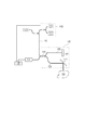
図1は本実施形態に係るOCTの装置構成を示す模式図である。
(Embodiment 1)
FIG. 1 is a schematic diagram showing an OCT apparatus configuration according to this embodiment.
本発明の実施形態1に係るOCTは、光源部としての波長掃引光源101、クロック生成部としてのkクロック(k−clock)系102、干渉光学系103、光検出部104、情報取得部105を有する。
The OCT according to the first embodiment of the present invention includes a wavelength swept
また、本実施形態に係るOCTにおいて、干渉光学系103は参照ミラー107、光導波路109、光カップラ110、走査ミラー111を有する。108は被検体(物体)である。次に、本実施形態に係るOCTを用いて物体の情報を取得する方法について説明する。
In the OCT according to the present embodiment, the interference
まず、干渉光学系103は、出射する光の波長を変化させる波長掃引光源101から出た光を、被検体108へ照射する照射光と参照光とに分波し、被検体108に照射された光の反射光と前記参照光による干渉光を発生させる。光検出部104は干渉光学系103で発生させた干渉光を受光する。また、k−clock系102は、波長掃引光源101から出射する光の波長変化に伴い、等波数間隔でクロック信号(kトリガ信号)を生成して情報取得部105に送信する。
First, the interference
k−clock系102は、等波数間隔で光を透過または反射する波長選択部106で構成可能である。例えば波長選択部106は長さが異なる二つの光路を含む干渉計で構成する。そして、この光路で干渉した光を差動光検出器あるいは通常の光検出器で検出することでk−clock系102を構築できる。
The k-
波長掃引光源101から出射された光をk−clock系102に導くと、波長掃引光源101の波長掃引に伴い、k−clock系固有の一定の光波数毎にk−clock系からkトリガ信号が生成される。干渉光学系103からの干渉信号をこのkトリガ信号に基づいてサンプリングすることにより、干渉信号を等波数間隔で取得することが可能である。
When the light emitted from the wavelength swept
情報取得部105は、干渉信号(干渉光の強度の時間波形)を、受信したkトリガ信号に基づいてサンプリングし、サンプリングしたデータをフーリエ変換して、物体の断層の情報を取得する。ここで、物体の情報は、典型的には断層像であるが、各断層からの反射光強度の数値の絶対値であってもよいし、規格化された値であってもよく、特に限定されない。以下では、物体の情報を物体の断層像として説明する。
The
本実施形態に係る光干渉断層計は、被検体上の同じ位置で、複数回、波長掃引光源101を用いて波長掃引して複数の干渉光を発生させる。 The optical coherence tomometer according to the present embodiment generates a plurality of interference lights by sweeping the wavelength using the wavelength swept light source 101 a plurality of times at the same position on the subject.
情報取得部105は、取得した複数の干渉信号を、互いに異なる位相(タイミング)、かつ、互いに同一の周波数でサンプリングする。干渉信号のサンプリングは、クロック生成部が発生させた、互いに異なる位相、かつ、互いに同一の波数間隔の複数のクロック信号に基づいて行う。例えば、nを自然数、光の波数をΔkとしたときに、n×Δkの波数間隔でクロック信号を生成し、情報取得部はこのクロック信号に基づき、被検体上の同じ位置で、n個の干渉信号を取得する。そして、取得したn個の干渉信号のサンプリング周波数を互いにΔk異なるようにする。
The
上述したように、サンプリングする波数間隔が短いほど、物体の情報を取得する際に、物体のより深い位置の情報を得られる。本実施形態のように、干渉信号を複数取得し、互いに異なるタイミング、かつ、互いに同一の波数間隔でサンプリングすることで、サンプリングする波数間隔を短くする場合と同様の効果が得られる。 As described above, when the wave number interval for sampling is shorter, information on a deeper position of the object can be obtained when the object information is acquired. As in the present embodiment, by obtaining a plurality of interference signals and sampling at different timings and at the same wave number interval, the same effect as in the case of shortening the sampling wave number interval can be obtained.
すなわち、被検体108の同じ位置における、干渉信号のサンプリングデータが複数取得され、各々のデータに基づいて断層像を取得し、それらの断層像を合成する。その結果、物体のより奥深い位置の情報が得られる。
That is, a plurality of sampling data of interference signals at the same position of the
また、被検体108の同じ位置における、干渉信号のサンプリングデータが複数取得され、それら複数のデータを合成することで、サンプリングデータの波数間隔が短くなることと同様の意味をもたらし、物体のより奥深い位置の情報が得られる。
In addition, a plurality of sampling data of the interference signal at the same position of the
また、本実施形態に係るOCTはさらに、被検体108への照射光の照射位置を変える走査ミラー111によって照射光の照射位置を変えることで、物体のある断層面の情報を取得することができる。一つの断層面の情報を取得するための走査をBスキャンという。一方、物体のある位置の断層の情報を取得するための波長掃引動作をAスキャンという。
Further, the OCT according to the present embodiment can acquire information on a tomographic plane where an object is present by changing the irradiation position of the irradiation light by the
走査ミラー111の制御は、不図示の制御部で行ってもよいし、上記情報取得部105が行ってもよい。なお、物体上の同じ位置で、複数の干渉信号を取得するために、物体上の同じ位置で、物体の情報を複数取得した後に、走査ミラー111を用いて照射光の照射位置を変えてもよい。また、物体の同じ位置で、物体の情報を1回取得した後に、走査ミラー111を用いて照射光の照射位置を変えて走査し、同じ走査工程を複数回繰り返すことで、複数の干渉信号を取得してもよい。
The control of the
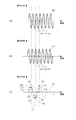
以下、本実施形態に係るOCTについて図2、3を用いて詳細に説明する。図2(a)は、kクロック(k−clock)信号、クロック信号(kトリガ信号)の一例を表す。kクロック信号は、k−clock系における干渉計で生成される、等波数間隔にピークを有する干渉信号である。kトリガ信号は、kクロック信号から生成される等波数間隔のクロック信号である。 Hereinafter, the OCT according to the present embodiment will be described in detail with reference to FIGS. FIG. 2A illustrates an example of a k clock (k-clock) signal and a clock signal (k trigger signal). The k clock signal is an interference signal having a peak at an equal wave number interval, which is generated by an interferometer in the k-clock system. The k trigger signal is a clock signal having an equal wave number interval generated from the k clock signal.
図2(b)は図2(a)のグラフを波数で微分したグラフである。図2(c)は、取得した干渉信号210の一例と、その干渉信号のサンプリング点を表した図である。図3は、図1の被検体108を光の照射方向から見た図である。
FIG. 2B is a graph obtained by differentiating the graph of FIG. FIG. 2C is a diagram showing an example of the acquired
本実施形態では、複数の断層像を取得する際に各々の断層像において干渉光学系103からの干渉信号を取得する際の光源の波数を、前記複数回の撮影ごとに異なる値に設定することが特徴である。
In the present embodiment, when acquiring a plurality of tomographic images, the wave number of the light source when acquiring the interference signal from the interference
例えば、図2に示すように、kクロック102で発生させうる信号201の上り勾配で横軸と交わる点(零クロスの点)202においてkトリガ信号を生成するとする。図2は縦軸がk−clock系102の差動光検出器からの出力、横軸は光の波数である。
For example, as shown in FIG. 2, it is assumed that a k trigger signal is generated at a point (zero cross point) 202 that intersects the horizontal axis with an ascending slope of a
なお、kトリガ信号は等波数間隔で生成されれば良く、kトリガ信号の生成点は上り勾配の零クロスの点に限るものではない。k−clock信号の山の点や谷の点、下り勾配零クロスの点も等波数間隔になっており、これらを用いても良い。上り勾配の零クロスの点、下り勾配の零クロスの点はそれぞれ、図2(a)の曲線において、傾きが正の点、負の点である。 The k trigger signal may be generated at equal wave number intervals, and the generation point of the k trigger signal is not limited to the zero-cross point of the upward gradient. The points of the peaks and valleys of the k-clock signal, and the points of the zero-gradient zero crossing also have equal wave number intervals, and these may be used. The zero-cross point of the upward gradient and the zero-cross point of the downward gradient are a positive point and a negative point, respectively, in the curve of FIG.
k−clock信号の上り勾配の零クロスの点は他にも点203、点204などがあり、これらの点に対応する光源の波数は互いに等間隔に離間しているため、これらの点で等波数間隔にkトリガ信号を生成することが可能である。
There are other points of the zero-crossing of the up-gradient of the k-clock signal, such as
被検体108上の測定対象部位302に対し波長掃引光源101からの光を照射し波長掃引を行い、上述のようにk−clock信号の上り勾配の零クロスの点でのkトリガ信号に基づいて干渉信号をサンプリングする。これにより、干渉信号210上の点211、点212、点213…を取得する。
Wavelength sweep is performed by irradiating the
次に、測定対象部位201に対しk−clock信号の山の点でkトリガを生成し、これに基づいて干渉信号を取得する。これは先の点202、203、204におけるサンプリングと比較してk−clock信号の1/4周期ずれた波数でkトリガを生成しデータサンプリングすることに相当する。
Next, a k-trigger is generated at the peak of the k-clock signal for the
このようなkトリガ信号を生成するためには、たとえばk−clock信号の山の点を検出する電気回路を用いても良い。あるいは電気的な微分回路を用いて、k−clock信号201を微分してk−clock信号230に変換し、この信号の上り勾配の零クロスの点231、点232、点233を検知することも可能である(図2(b))。
In order to generate such a k trigger signal, for example, an electric circuit for detecting a peak point of the k-clock signal may be used. Alternatively, by using an electrical differentiating circuit, the k-
この操作により、干渉信号210上の点214、点215、点216…が取得される。
By this operation, points 214, 215, 216,... On the
同様の操作を繰り返し、干渉信号210上の点217、点218、点219…を取得し更に点220、点221、点222…を取得する。
The same operation is repeated, and points 217, 218, 219... On the
上述の操作により、計4回の干渉信号取得結果を用いて干渉信号210を、1回の波長掃引動作と比較して4倍の密度で等波数間隔に高密度にデータサンプリングすることができる。
By the above-described operation, the
干渉信号を取得する波数間隔を4分の1にする事は、OCTを用いて取得した断層像(以下、OCT像と略すことがる)で4倍の深さの部位まで画像化出来ることに相当し、高深達なOCT像を得る事が可能となる。 The fact that the wave number interval for acquiring the interference signal is reduced to a quarter means that a tomographic image acquired by using OCT (hereinafter abbreviated as an OCT image) can be imaged up to a site four times deeper. Correspondingly, a deep OCT image can be obtained.
また高深達な断層像を得るために、本実施形態ではより高速で高価なAD変換素子を用いるのではなく、同じ速度のAD変換素子を用いつつ、高深達な画像を得ることができるため、装置コストの観点から好適である。 In addition, in order to obtain a high-depth tomogram, in this embodiment, a high-depth image can be obtained while using a high-speed and expensive AD conversion element, but using the same speed AD conversion element. This is preferable from the viewpoint of apparatus cost.
また、本実施形態に係るOCTの特徴は以下の2つである。1つは、後処理でより高密度且つ等波数間隔に取得したデータとして再構成出来るように、複数回の画像取得においてkトリガ信号の生成波数を異ならせる。2つ目は、該複数回の画像取得時のkトリガ生成波数が最終的に互いに等波数間隔に離間しているように設定する。 The OCT according to the present embodiment has the following two features. One is to vary the generated wave number of the k trigger signal in a plurality of image acquisitions so that it can be reconstructed as data acquired at higher density and equal wave number intervals in post-processing. The second setting is such that the k-trigger generated wave numbers at the time of the plurality of image acquisitions are finally separated from each other by equal wave number intervals.
被検体上のある直線310上の複数の点で干渉信号を取得し、直線310の部位の断層像を取得することを考える。
Consider that interference signals are acquired at a plurality of points on a certain
断層画像を取得する工程は通常のOCTでは以下の工程を含む。
(1)被検体のある位置で干渉信号を1回取得する。
(2)(1)の信号取得部位を直線310上で変えながら各点で干渉信号を取得し、断層像を1枚取得する。
The process of acquiring a tomographic image includes the following processes in normal OCT.
(1) An interference signal is acquired once at a position of the subject.
(2) While changing the signal acquisition site of (1) on the
さらに、
(3)(2)の工程を繰り返し多数枚の画像を取得し、後ほど画像処理で重ね合わせノイズを除去する、という工程を追加してもよい。
further,
(3) The process of (2) may be repeated to acquire a large number of images, and a process of removing overlay noise by image processing later may be added.
直線310に対応する断層像を取得するためには、光を照射する点を点302、点303、点304と変え、各点で波長掃引を行い各点での干渉信号を取得する。これをフーリエ変換することで各点での断層像を取得する。各点での断層像を並べて一枚の画像とすることで直線310に対応する断層像が作成出来る。
In order to acquire a tomographic image corresponding to the
従来のOCTではこの4枚の画像の全てにおいて、そのkトリガ信号を生成する波数が互いに同じ位相である。このとき、kトリガ信号を生成する波数間隔を4×Δkとする。つまり干渉信号を取得する際の光源の波数は等波数間隔4×Δkに離間している。このようにして得た複数の干渉信号から断層像を取得し、合成する場合、画質は改善するが、被検体のより奥深い部位での像を取得することはできない。 In the conventional OCT, in all of these four images, the wave numbers for generating the k trigger signal have the same phase. At this time, the wave number interval for generating the k trigger signal is 4 × Δk. That is, the wave number of the light source when acquiring the interference signal is separated by an equal wave number interval of 4 × Δk. When tomographic images are acquired from a plurality of interference signals obtained in this way and synthesized, the image quality is improved, but images at deeper parts of the subject cannot be acquired.
これに対し本実施形態に係るOCTでは、同じ測定部位に対して複数の干渉信号取得を行い、患部の画像を撮影する場合、それぞれの干渉信号を取得する際に、互いに位相が異なるようにkトリガ信号を生成しデータを取得する。 On the other hand, in the OCT according to the present embodiment, when a plurality of interference signals are acquired for the same measurement site and an image of the affected area is captured, the respective phases are different from each other when acquiring each interference signal. Generate trigger signal and acquire data.
同じ測定部位の断層構造に対して4回信号取得する場合、それぞれの信号取得ではデータサンプリングの波数間隔は上記と同様に4×Δkである。 When signals are acquired four times for the tomographic structure of the same measurement site, the data sampling wave number interval is 4 × Δk, as described above, for each signal acquisition.
本実施形態では、上記の4回の信号取得ごとにデータサンプリングの波数がΔkずつ異なるように設定されている。 In the present embodiment, the wave number of data sampling is set to be different by Δk for each of the above four signal acquisitions.
そして結果的に、得られた干渉信号を合成し、データサンプリングの波数間隔がΔkであるような一つの干渉信号を作成する。 As a result, the obtained interference signals are combined to create one interference signal whose data sampling wave number interval is Δk.
上記のように、直線310上の各点において干渉信号を複数回取得し、且つ干渉信号を複数回取得し、そのデータサンプリングの波数間隔をΔkにするためには、いくつかの手法がある。 As described above, there are several methods for acquiring the interference signal at each point on the straight line 310 a plurality of times, acquiring the interference signal a plurality of times, and setting the wave number interval of the data sampling to Δk.
例えば測定対象部位の各点ごとに、k−clock信号におけるデータサンプリングの波数を、k−clock信号の周期の1/4に相当するΔkずつずらしながら4回連続して干渉信号を取得する。そして次に、(2)の工程で測定対象部位上の直線310上の隣の点に移り、再度データサンプリングを4回連続で行う。この工程を繰り返す。この工程を繰り返すことで、ある直線310上の点に対応する干渉信号が得られ、各点ではデータを取得する際の波数がΔkずつ異なる複数の干渉信号を得られる。
For example, for each point of the measurement target region, the interference signal is acquired four times continuously while shifting the wave number of data sampling in the k-clock signal by Δk corresponding to ¼ of the period of the k-clock signal. Then, in the step (2), the process moves to an adjacent point on the
最終的にΔkずつサンプリングする波数が異なる信号を4本取得する順序は、上記のようにΔkずつ逐次ずらして行く取得方法に限るものではない。まずサンプリングする波数が2Δkずつ異なるデータのセットを取得してもよい。 The order of finally acquiring four signals with different wave numbers sampled by Δk is not limited to the acquisition method of sequentially shifting by Δk as described above. First, data sets whose sampling wave numbers are different by 2Δk may be acquired.
(光源部)
本実施形態において、光源部は光の波長を変化させる光源であれば特に限定されない。本実施形態に係るOCTを用いて物体の情報を得るためには、この光源部から出る光の波長を時間とともに所望の波長範囲内で掃引させる必要がある。
(Light source)
In the present embodiment, the light source unit is not particularly limited as long as it is a light source that changes the wavelength of light. In order to obtain object information using the OCT according to the present embodiment, it is necessary to sweep the wavelength of light emitted from the light source unit within a desired wavelength range with time.
本実施形態における光源部として例えば、面発光レーザー、回折格子やプリズム等を用いた外部共振器型の波長掃引光源、共振器長可変のファブリペローチューナブルフィルタを用いる各種外部共振器型光源をもちいることができる。あるいは、サンプルドグレーティングを用いて波長を変化させるSSG−DBRや波長可変のMEMS−VCSELなどを用いることもできる。また、ファイバレーザーを用いることもできる。ファイバレーザーとしては、分散チューニング方式でもよく、フーリエドメインモードロック方式であってもよい。 As the light source unit in the present embodiment, for example, a surface emitting laser, an external resonator type wavelength swept light source using a diffraction grating or a prism, and various external resonator type light sources using a Fabry-Perot tunable filter with a variable resonator length are used. Can be. Or SSG-DBR which changes a wavelength using a sampled grating, MEMS-VCSEL of wavelength variable, etc. can also be used. A fiber laser can also be used. The fiber laser may be a dispersion tuning method or a Fourier domain mode lock method.
回折格子やプリズム等を用いた外部共振器型の波長掃引光源としては、共振器に回折格子を設けて光を分光させ、ポリゴンミラーや、回転する円盤上にストライプ状の反射ミラーを設けたものを用いて出射させる波長を連続的に変え波長掃引光源などが挙げられる。 As an external resonator type wavelength sweep light source using a diffraction grating, a prism, etc., a resonator is provided with a diffraction grating to disperse light, and a polygon mirror or a striped reflection mirror is provided on a rotating disk. A wavelength swept light source or the like may be used by continuously changing the wavelength of light emitted by using.
(光検出部)
本実施形態における光検出部では、干渉光の強度を電圧などの電気の強度に変換するものであれば特に限定されない。干渉信号の情報は、この光検出部で受光電圧の時間波形の情報へと変換される。
(Light detector)
In the light detection part in this embodiment, if the intensity | strength of interference light is converted into the intensity | strength of electricity, such as a voltage, it will not specifically limit. The information of the interference signal is converted into information of the time waveform of the received light voltage by this light detection unit.
(物体)
本実施形態において物体とは、本実施形態に係るOCTによる測定の対象となるものであり種類は特に限定されない。例えば、眼球、皮膚、血管、歯などの生体が挙げられる。
(object)
In the present embodiment, the object is a measurement target by OCT according to the present embodiment, and the type is not particularly limited. Examples include living bodies such as eyeballs, skin, blood vessels, and teeth.
(表示部)
本実施形態に係るOCTは、情報取得部で取得した物体の情報が断層像であり、取得した断層像を表示する表示部を有していてもよい。
(Display section)
In the OCT according to the present embodiment, the object information acquired by the information acquisition unit is a tomographic image, and may include a display unit that displays the acquired tomographic image.
(用途)
上記本実施形態に係るOCTは、眼底の断層像を得るための眼科撮影、皮膚撮影、血管造影、歯科撮影、などの医用診断に用いることができる。
(Use)
The OCT according to the present embodiment can be used for medical diagnosis such as ophthalmic imaging, skin imaging, angiography, and dental imaging for obtaining a tomographic image of the fundus.
(実施形態2)
次に本発明の実施形態2に係るOCTについて説明する。ここでは、実施形態1と異なる点について述べ、共通する事項については説明を省略する。
(Embodiment 2)
Next, OCT according to Embodiment 2 of the present invention will be described. Here, differences from the first embodiment will be described, and description of common matters will be omitted.
実施形態1で説明した、上記(1)の工程においてkトリガ信号を固定し、測定対象部位上の点302において干渉信号を取得する。そして工程(2)で測定対象部位を直線310上の隣の点303に変え、データサンプリングの波数を工程(1)と同じ値に固定したまま1回干渉信号を取得する。この操作を繰り返し、直線310上の各点に対して干渉信号を取得する。
In the step (1) described in the first embodiment, the k trigger signal is fixed, and an interference signal is acquired at the
次に、k−clock信号に対するデータサンプリングの波数を、前述の波数からk−clock信号の周期の1/4であるΔkずらして、上述と同様に直線310上の各点302、点303、…において干渉信号を取得する。
Next, the wave number of data sampling with respect to the k-clock signal is shifted from the aforementioned wave number by Δk which is ¼ of the period of the k-clock signal, and the
そして上記のΔkずつ波数をずらした干渉信号取得を計4回行うことで、最終的に直線310に対し各点でkトリガ信号の位相が異なる複数の干渉信号を得られている状態となる。
The interference signal acquisition with the wave number shifted by Δk is performed a total of four times, so that a plurality of interference signals having different phases of the k trigger signal at each point with respect to the
次に、測定対象物体上の各点に対して、kトリガ信号の位相が互いに異なる複数の干渉信号が得られた後の信号処理について以下に述べる。高深達なOCT像を生成するためには、4×Δkの波数間隔の干渉信号のデータ4つから、波数間隔Δkの1つの干渉信号を合成しこれをフーリエ変換すればよい。 Next, signal processing after a plurality of interference signals having different phases of the k trigger signal are obtained for each point on the measurement target object will be described below. In order to generate a high-depth OCT image, it is only necessary to synthesize one interference signal having a wave number interval Δk from four pieces of interference signal data having a wave number interval of 4 × Δk and Fourier-transform this.
なお、最終的にΔkずつサンプリングの波数が異なる信号を4つ取得する順序は上記のようにΔkずつ逐次ずらして行く取得方法に限るものではない。まず2×Δkずつタイミングがずれたデータのセットを取得してもよい。 The order of finally acquiring four signals having different sampling wavenumbers by Δk is not limited to the acquisition method of sequentially shifting by Δk as described above. First, a data set whose timing is shifted by 2 × Δk may be acquired.
これは最終的に元のデータの波数間隔の1/4の波数間隔のデータを取得する前に、途中で半分の取得間隔のデータを得られ、逐次得られるデータから画像が高深達化されていく様子を確認することが容易であるという理由から好適である。 This is because, before finally acquiring the data of the wave number interval of 1/4 of the wave number interval of the original data, the data of the half acquisition interval is obtained on the way, and the image is deepened from the sequentially obtained data. It is preferable because it is easy to confirm the situation.
上述のように最終的にΔkの波数間隔のデータを得る場合、取得途中でm×Δkの(但しn≠mの整数)波数間隔になるような干渉信号のデータのセットを取得する順序で測定することができる。測定の最終段階まで到達しない途中段階でも多少は深さ方向の撮像域が増大している画像を逐次取得出来るためである。また、上述のように位相が互いに異なるkトリガ信号を用いて、4回取得した干渉信号のそれぞれをフーリエ変換し、各干渉信号からOCT像を一枚一枚構成してもよい。この場合にはデータサンプリングの波数間隔が4×Δkである同じ深さの絵が4枚出来るので、従来と同様に同じ深さの絵を4枚重ねて画質改善に用いることも可能である。 As described above, when the data of the wave number interval of Δk is finally obtained, the measurement is performed in the order of obtaining the data set of the interference signal that becomes the wave number interval of m × Δk (where n ≠ m) during the acquisition. can do. This is because even in the middle stage where the final stage of measurement is not reached, it is possible to sequentially acquire images with a somewhat increased imaging area in the depth direction. Further, as described above, each of the interference signals acquired four times may be Fourier-transformed using k trigger signals having different phases, and an OCT image may be formed one by one from each interference signal. In this case, four pictures having the same depth with a data sampling wave number interval of 4 × Δk can be formed, and therefore, four pictures having the same depth can be overlapped and used for image quality improvement as in the prior art.
つまり本実施形態に係るOCTでは、複数回の干渉信号の取得の際に用いる、サンプリングする波数を互いに異ならせることで、より高密度な波数間隔でサンプリングした干渉信号を再構成でき、高深達化なOCT像を得られる。あるいは上記に加えて、従来と同様に、複数の干渉信号データそれぞれからOCT画像を構成し、これらの絵を重ね合わせて高画質化を行うことも可能である。 In other words, in the OCT according to the present embodiment, the interference signals sampled at higher density wave number intervals can be reconfigured by differentiating the sampling wave numbers used when acquiring the interference signals multiple times, and the depth of the signals is increased. An OCT image can be obtained. Alternatively, in addition to the above, it is also possible to construct an OCT image from each of a plurality of interference signal data and superimpose these pictures to improve the image quality, as in the past.
したがって従来OCTと比較して、高深達化のために高速なAD変換素子は必要なくコスト低減に効果がある。さらにデータ取得後のデータ処理方法の選択肢が増えるメリットもある。 Therefore, as compared with the conventional OCT, a high-speed AD conversion element is not required for increasing the depth, and the cost can be reduced. In addition, there is an advantage that the choice of data processing methods after data acquisition is increased.
また更にこれら両方の操作を両方取り入れ、画像の高深達化と高画質化の両立も可能である。 Furthermore, both of these operations can be incorporated to achieve both high depth of image and high image quality.
つまり、ある部位の同じ画像を40枚撮影し、これを重ねて画像処理する場合、単純に40枚を同じデータサンプリングの波数で取得して画像の高画質化、即ちSN比を高くすることも可能である。しかし本実施形態では、これと同じデータ取得時間において、ある部位の画像を40枚取得し、しかもこの40枚の画像は互いにデータサンプリングのタイミングがΔkずつずれた4枚の組になっている。 In other words, when 40 images of the same part are captured and image processing is performed by superimposing these images, it is possible to simply obtain 40 images with the same data sampling wavenumber to improve the image quality, that is, to increase the SN ratio. Is possible. However, in the present embodiment, 40 images of a certain part are acquired at the same data acquisition time, and the 40 images are in a group of 4 images whose data sampling timings are shifted from each other by Δk.
したがって、この40枚を単純に重ねて従来技術と同様に高SN化も可能であり、4枚分のデータから、4倍の深さまで見える1枚の高深達画像を合成する事も可能である。つまり40枚分のデータから4倍の深さの画像を10枚生成可能である。これらを10枚重ね合わせる画像処理を行うことで、SN比を高くすることができる。 Therefore, this 40 images can be simply overlapped to increase the SN as in the prior art, and it is also possible to synthesize one high depth image that can be seen up to 4 times deep from the data for 4 images. . In other words, ten images that are four times deeper can be generated from 40 pieces of data. By performing image processing to superimpose these 10 sheets, the SN ratio can be increased.
なお、本実施形態では、最終的に深い部位まで画像化する事を想定しているため、SS−OCT装置に含まれる光源の瞬時線幅が十分に細い事が好適である。つまり、最終的に画像化される深さの部位からの反射光に対して可干渉性を有するようなコヒーレンス長を有する光源であることが好適である。 In the present embodiment, since it is assumed that an image is finally formed up to a deep part, it is preferable that the instantaneous line width of the light source included in the SS-OCT apparatus is sufficiently narrow. In other words, it is preferable that the light source has a coherence length that has coherence with respect to the reflected light from the part of the depth to be finally imaged.
また、本実施形態ではもともとのサンプリングする際の波数間隔が4×Δkであったところを、4つのデータを合成して一つのΔkの波数間隔のデータにしている。 In the present embodiment, the original wave number interval at the time of sampling is 4 × Δk, and four pieces of data are combined into one wave number interval data of Δk.
AD変換素子にはいくつかのタイプがあるが、その中の1つの例としては内部にサンプリングアンドホールド回路を有するタイプがある。このタイプの素子では外部からの入力値であるアナログ信号を電圧としてあるコンデンサに取りこむ。コンデンサが充電できたら、次にこのコンデンサの電圧を基にアナログ値をデジタル値に変換し出力する。 There are several types of AD conversion elements, and one of them is a type having a sampling and holding circuit therein. In this type of element, an analog signal which is an input value from the outside is taken as a voltage into a certain capacitor. Once the capacitor is charged, the analog value is converted to a digital value based on the voltage of the capacitor and then output.
アナログ値を取得しデジタル値を出力をするまでの全時間をTとし、このうち上記コンデンサが充電されるまでの時間をt1、コンデンサの電圧を読みとってデジタル値を出力するまでの時間をt2とする。この場合、図9(a)に示すようにT=t1+t2である。このような工程を繰り返してアナログデータを次々とデジタルデータに変換し出力する。 The total time from acquiring the analog value to outputting the digital value is T, of which t1 is the time until the capacitor is charged and t2 is the time until the digital value is output after reading the capacitor voltage. To do. In this case, T = t1 + t2 as shown in FIG. By repeating such a process, analog data is converted into digital data one after another and output.
図9から判るように、AD変換素子がアナログ入力値を読みこむ時間はt1だけであり、残りのt2の時間のアナログ入力値はAD変換素子に取得されていない。 As can be seen from FIG. 9, the time for the AD conversion element to read the analog input value is only t1, and the analog input value for the remaining time t2 is not acquired by the AD conversion element.
したがって、本実施形態のようにkトリガ信号の位相をずらして高密度サンプリングを行うためには、図9(b)に示すような、t1だけずらした時間間隔で次々とサンプリングすればよい。これによりデータ取得間隔をT/t1倍程度に高密度にすることが可能であり好適である。サンプリングアンドホールド回路を有するAD変換素子では、t1はTの1割から2割程度であることが多い。この場合、本実施形態に係るOCTによって最終的に波数間隔が小さいデータサンプリングを行う場合、もともとのデータサンプリングの波数間隔の1/4乃至1/5程度までに設定することが好適であると考えられる。 Therefore, in order to perform high-density sampling by shifting the phase of the k trigger signal as in the present embodiment, it is only necessary to sample one after another at time intervals shifted by t1 as shown in FIG. 9B. As a result, the data acquisition interval can be increased to a high density of about T / t1, which is preferable. In an AD conversion element having a sampling and holding circuit, t1 is often about 10% to 20% of T. In this case, when data sampling is finally performed with a small wave number interval by the OCT according to the present embodiment, it is considered preferable to set the wave number interval to about 1/4 to 1/5 of the original data sampling wave interval. It is done.
さらに、本実施形態に係るOCTは、k−clock信号またはkトリガ信号に対して波長や波数の絶対値を割り付ける、すなわち測定するための測定部112を設けていても良い。測定部112としては、波長掃引光源の発光波長帯域の中に選択波長が1つあるいは2つであるであるような波長選択素子を用いることが好適である。例えばフリースペクトラルレンジ(Free Spectral Range:FSR)が大きく、波長掃引光源の波長掃引帯域の上限近くと下限近くにそれぞれ選択波長が1つずつ存在するようなファブリペローフィルタを用いることができる。
Furthermore, the OCT according to the present embodiment may be provided with a
なお、これらの選択波長はファブリペローフィルタのギャップ長などから予め判っているものとする。 These selected wavelengths are known in advance from the gap length of the Fabry-Perot filter.
あるいは、特定の波長だけを透過するバンドパスフィルタを用いる事もできる。 Alternatively, a bandpass filter that transmits only a specific wavelength can be used.
例えば上記波長選択素子にて波長掃引光源からの透過光強度をモニタリングし、光が選択される時にk−clock信号を同時にモニタリングすれば、k−clock信号から生成される各kトリガ信号に対して光の波長(波数)を割り付けられる。 For example, when the transmitted light intensity from the wavelength swept light source is monitored by the wavelength selection element and the k-clock signal is simultaneously monitored when light is selected, each k trigger signal generated from the k-clock signal is monitored. The wavelength (wave number) of light can be assigned.
このようにk−clock信号に対して光の波数を割り付けることが出来れば、光源の波長掃引開始のタイミング、あるいは終了のタイミングを確認する事ができる。あるいはOCT像を出力するために用いるデータの光周波数に上限下限がある場合にはそれらの光周波数で波長選択素子の透過光強度が増大するように設定し、光源波長をモニタしておくこともできる。さらには波長掃引光源が所望の波長掃引範囲を所望の波長掃引速度で動作出来ているか、などの光源の状態確認に使う事も出来る。 If the wave number of light can be assigned to the k-clock signal in this way, it is possible to confirm the wavelength sweep start timing or end timing of the light source. Alternatively, when there are upper and lower limits on the optical frequency of the data used to output the OCT image, the transmission light intensity of the wavelength selection element is set to increase at those optical frequencies, and the light source wavelength may be monitored. it can. Furthermore, it can also be used to check the state of the light source, such as whether the wavelength swept light source can operate in a desired wavelength sweep range at a desired wavelength sweep speed.
(実施例1)
以下に、本発明の実施例について図4を用いて説明する。
Example 1
Hereinafter, an embodiment of the present invention will be described with reference to FIG.
図4は本実施例に係るOCTの構成を示す構成図である。本実施例にでは被検体は眼底であるとする。光源部としての波長掃引光源部401と、参照部を構成する参照光光路用ファイバ402、干渉部を構成するファイバカップラ403、反射ミラー404を配置する。
FIG. 4 is a configuration diagram showing the configuration of the OCT according to the present embodiment. In this embodiment, it is assumed that the subject is the fundus. A wavelength swept
さらに、検体測定部を構成する検査光光路用ファイバ405、照射集光光学系406、走査ミラー407を接続する。
Further, the inspection light
これに加え、受光用ファイバ408、光検出部としてのフォトディテクタ409、照射用ファイバ410、情報取得部としての信号処理部411、表示部としての画像出力モニタ413を接続する。さらに、信号処理部411はk−clock信号を微分処理する微分回路430、切り替え器431、アナログデジタル変換素子432、演算部433を有する。
In addition, a
そして、光源制御部412を接続した構成によりOCT装置を構成できる。414は検査対象物(物体)である。420、421はファイバに光を結合し、またファイバからの光をコリメートする為のコリメータである。
And an OCT apparatus can be comprised by the structure which connected the light
なお、干渉光学系を構成するファイバは本実施例ではシングルモードファイバで構成するがこの限りではない。また、波長掃引光源部401は図4(b)に示すように、波長掃引光源415、k−clock系417、バンドパスフィルタ418からなる。
Although the fiber constituting the interference optical system is a single mode fiber in this embodiment, this is not restrictive. The wavelength sweep
本実施例では、k−clock系として干渉計の両腕の光路長差が8mmであるマイケルソン干渉計からの光を差動光検出器に導入する系を用いる。この干渉計から出力される干渉信号は光の周波数が18.737GHz毎にkトリガ信号を生成する。波長掃引光源415の波長掃引周波数は50kHz(波長掃引周期は20us)であり、波長掃引範囲は1000nmから1090nmである。したがって、波長掃引光源415の一回の波長掃引あたりのkトリガ信号の生成回数は1321回である。光源の掃引速度は一定に制御され図5に示す様態である。この時、光源から出る光の波長を掃引中のkトリガ信号の生成周波数は66MHzである。したがって、信号処理部内の各素子は信号周波数66MHz以上に対応できる素子を用いる。
In this embodiment, a system that introduces light from a Michelson interferometer in which the optical path length difference between both arms of the interferometer is 8 mm into the differential photodetector is used as the k-clock system. The interference signal output from the interferometer generates a k-trigger signal every light frequency of 18.737 GHz. The wavelength sweep
バンドパスフィルタ418は透過波長が光源の発光スペクトルの短波長端に近い波長1000nmの光を透過する。
The
波長掃引光源415には、光源制御部412から制御信号が入力される。
A control signal is input from the light
波長掃引光源415は光源制御部によりその発振波長や強度及びその時間変化を制御する。
The wavelength swept
波長掃引光源415から出射された光はファイバカップラにおいて参照光光路用ファイバ402及び検査光光路用ファイバ405に分割されて導入される。
The light emitted from the wavelength swept
さらに、参照光光路用ファイバの先端にはコリメータ421が装着され平行光が反射ミラー404に照射される。そして反射ミラー404で光は反射され受光用ファイバに導入されフォトディテクタ409に到達する。
Furthermore, a
同時に、ファイバカップラ403にて検査光光路用ファイバ405に導入された光は検査物体414に照射され、後方散乱光が被験物体の内部及び表面から発生する。
At the same time, the light introduced into the inspection light
後方散乱光は照射集光光学系406を通してファイバカップラからフォトディテクタ409に集光される。
The backscattered light is condensed from the fiber coupler to the
フォトディテクタ409受光された光は信号処理部411にてスペクトル信号に変換され、さらにフーリエ変換を施すことで被験物体の断層情報を取得する。
The light received by the
本実施例では、つぎのようにOCT像を形成する。 In this embodiment, an OCT image is formed as follows.
観察対象物体上の点302に光を照射する。
The
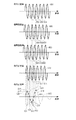
k−clock系417は、k−clock信号601の上り勾配の零クロスの点、例えば点602、点603、点604にてkトリガ信号を生成する。波長掃引光源415を波長掃引し、kトリガ信号を基に干渉信号上の点611、点612、点613を取得する。図6の横軸は光の波数であり、光波数は光の周波数に2πを光速度で割った値を乗ずれば求まる。
The k-
図7は横軸が時間であり、k−clock信号701を図示している。ここで信号710はバンドパスフィルタ418を透過する光の強度であり、時刻711における発光波長が1000nmである。
In FIG. 7, the horizontal axis is time, and the k-
また、時刻711からk−clock信号で3/4周期分進んだ点702で生成されるkトリガは、波長1000nmの光の周波数が299.79THzでありk−clockが18.7GHz周期であることから299.77THzであることがわかる。なお、同様にして点703や点704の光周波数も計算できる。
In addition, the k trigger generated at the
次に切り替え器430によりk−clock信号601を微分回路431に通し、微分したk−clock信号630を生成する。同様にk−clock信号630の上り勾配の零クロスの点、例えば点631、点632、点633にてkトリガ信号を生成し、干渉信号上の点614、点615、点616を取得する。
Next, the k-
さらに切り替え器430によりk−clock信号を微分回路431に通し、k−clock信号650を生成する。同様にk−clock信号650の上り零クロスの点、例えば点651、点652、点653にてkトリガ信号を生成し、干渉信号上の点617、点618、点619を取得する。
Further, the switch 430 passes the k-clock signal to the differentiating
そして切り替え器430によりk−clock信号を微分回路431に通し、k−clock信号670を生成する。同様にk−clock信号670の上り零クロスの点、例えば点671、点672、点673にてkトリガ信号を生成し、干渉信号上の点620、点621、点622を取得する。
Then, the switch 430 passes the k-clock signal through the differentiating
得られた干渉信号上の点611、点612、…、点621、点622のデータを合成し、干渉信号610が生成される。この干渉信号データの取得波数間隔は18.737GHzの1/4の4.684GHzである。
The data of the
そして、この干渉信号をフーリエ変換することで、ある一点での物体の断層情報を取得する。 Then, the tomographic information of the object at a certain point is obtained by Fourier transforming this interference signal.
次に物体に対する照射位置を10um変位させ点303に照射する。そして上記と同様に4回干渉信号を取得し、同様にこの点における、波数間隔4.684GHzのデータによる断層情報を取得する。これらの一連の操作により、断層面310における断層情報を得ることが出来る。
Next, the irradiation position on the object is displaced by 10 μm, and the point 303 is irradiated. Then, the interference signal is acquired four times in the same manner as described above, and similarly, the tomographic information based on the data having the wave number interval of 4.684 GHz at this point is acquired. By these series of operations, tomographic information on the
本実施例に係るOCTによれば、観察対象部位の各点において、k−clockに対するデータ取得波数を異ならせた4つの信号を連続で取得する。このため観察対象物体が動く可能性がある場合など、高速に観察対象物体上のある点あるいは狭い領域の更深達画像を取得したい場合に好適である。 According to the OCT according to the present embodiment, four signals with different data acquisition wave numbers for k-clock are continuously acquired at each point of the observation target region. For this reason, it is suitable for a case where it is desired to acquire a deeper depth image of a certain point or a narrow area on the observation target object at high speed, such as when the observation target object may move.
(実施例2)
以下に、本発明の実施例について説明するが、実施例1と共通する事項については説明を省略する。本実施例に係るOCTの装置構成は図4と同様である。
(Example 2)
Examples of the present invention will be described below, but descriptions of matters common to Example 1 will be omitted. The apparatus configuration of the OCT according to the present embodiment is the same as that shown in FIG.
本実施例では、つぎのようにOCT像を形成する。 In this embodiment, an OCT image is formed as follows.
k−clock系417は、k−clock信号601の上り零クロスの点602、点603、点604…にてkトリガ信号を生成する。
The k-
まず照射位置を点302にし、波長掃引光源415からの光を照射し、kトリガ信号を基に干渉信号の点611、点612、点613を取得する。次に照射位置を点303に移して、同様に干渉信号を取得する。
First, the irradiation position is set to the
この時も干渉信号取得のkトリガは点602、点603、点604…であり、k−clock信号上の上り零クロスの点である。このようにk−clock上のkトリガ生成波数を固定したまま、照射位置を断層面310上の点302、点303、点304…と順次移して行きながら干渉信号を取得する。
Also at this time, the k trigger for acquiring the interference signal is the
この結果、断層面310上の全ての点について、k−clockに対して同じkトリガ生成波数で干渉信号が取得される。
As a result, for all points on the
仮にこの状態でこれらの信号をフーリエ変換すれば、通常のOCTで断層面310の画像を取得する方法と同様であるが、本発明ではさらにkトリガ生成波数を異なる値に設定し、継続して干渉信号を取得する。切り替え器430によりk−clock信号601を微分回路431に通し、k−clock信号630を生成する。同様にk−clock信号630の上り零クロスの点、点631、点632、点633にてkトリガ信号を生成し、断層面310上の点302において干渉信号上の点614、点615、点616を取得する。次に照射位置を点303に移して、同様に干渉信号を取得する。このようにk−clock上のトリガ信号生成タイミングを固定したまま、照射位置を断層面310上の点304、…と順次移しながら干渉信号を取得する。
If these signals are Fourier-transformed in this state, it is the same as the method of acquiring an image of the
さらに切り替え器430によりk−clock信号630を微分回路431に通し、k−clock信号650を生成する。同様にk−clock信号の上り零クロスの点、点651、点652、点653、…にてkトリガ信号を生成し、断層面310上の点302において干渉信号上の点617、点618、点619、…を取得する。次に照射位置を点303に移して、同様に干渉信号を取得する。このようにk−clock上のトリガ信号生成タイミングを固定したまま、照射位置を断層面310上の点304、…と順次移しながら干渉信号を取得する。
Further, the switch 430 passes the k-clock signal 630 through the differentiating
最後に切り替え器430によりk−clock信号650を微分回路431に通し、k−clock信号670を生成する。同様にk−clock信号670の上り零クロスの点、点671、点672、点673、…にてトリガ信号を生成し、断層面310上の点302において干渉信号上の点620、点621、点622、…を取得する。次に照射位置を点303に移して、同様に干渉信号を取得する。このようにk−clock上のトリガ信号生成タイミングを固定したまま、照射位置を断層面310上の点304、…と順次移しながら干渉信号を取得する。
Finally, the switch 430 passes the k-
これらの操作により、断層面310上の全ての点302、点303、点304…に対して、k−clock信号に対するトリガ生成の波数が異なる4つの干渉信号を取得出来る。
By these operations, four interference signals having different trigger generation wave numbers for the k-clock signal can be acquired for all
最終的には例えば点302において干渉信号上の点611、点612、…、点621、点622が得られる。
Finally, for example, at a
これらの点から一つの干渉信号を合成し干渉信号610を生成する。
From these points, one interference signal is combined to generate an
この干渉信号610をフーリエ変換し、OCT画像を得る。このOCT画像は、上述の干渉信号を合成する前の状態の断層像の4倍の深さまで画像化されている。
The
本実施例の装置によれば、最終的に合成する干渉信号を基に断層像が4倍の画像を得られる前の途中の段階において、浅い範囲の画像が逐次得られる手法である為、患部の状態や撮影場所などを随時確認したい場合などに好適である。 According to the apparatus of the present embodiment, an image of a shallow range is sequentially obtained in the middle stage before an image having a quadruple tomogram is obtained based on the interference signal to be finally synthesized. This is suitable when the user wants to check the state of the camera, the shooting location, etc. at any time.
(実施例3)
以下に、本発明の実施例について説明するが、実施例1、2と共通する事項については説明を省略する。
(Example 3)
Examples of the present invention will be described below, but descriptions of matters common to Examples 1 and 2 will be omitted.
本実施例では、図8に示すように、干渉信号を差動検出器を用いて取得する構成となっている。 In this embodiment, as shown in FIG. 8, the interference signal is acquired using a differential detector.
図8において、光源部801と、アイソレータ802、参照部を構成する参照光光路用ファイバ806、偏波コントローラ818、干渉部を構成するファイバカップラ805、反射ミラー807を配置する。コリメータ820、コリメータ821も配置する。図4の系と同様、光源部801には不図示のk−clock系、波長選択素子を含む。
In FIG. 8, a
さらに、検体測定部を構成する検査光光路用ファイバ814、偏波コントローラ819、照射集光光学系815、照射位置走査用ミラー808を接続する。
Further, an inspection light
これに加え、光検出部を構成するファイバカップラ803、ファイバカップラ804、受光用ファイバ816、受光用ファイバ817、バランスフォトディテクタ810、画像処理部を構成する信号処理装置811、画像出力モニタ813を接続する。図4の系と同様、信号処理装置811には不図示の微分回路や切替器、演算素子などを含む。
In addition, a
そして、光源部を構成する光源制御装置812を接続した構成により光干渉断層撮像装置を構成できる。809は検査対象物である。
And the optical coherence tomography apparatus can be comprised by the structure which connected the light
101 光源部(波長掃引光源)
102 クロック生成部(k−clock系)
103 干渉光学系
104 光検出部
105 情報処理部
101 Light source (wavelength swept light source)
102 Clock generator (k-clock system)
103 Interferometric
Claims (24)
前記光源部からの光を物体へ照射する照射光と、参照光とに分波し、前記物体に照射された光の反射光と前記参照光による干渉光を発生させる干渉光学系と、
前記干渉光を受光する光検出部と、
前記光源部から出射された光を用いて、所定の波数間隔の周期のクロック信号を発生させるクロック生成部と、
前記物体上の同じ位置で得た前記干渉光の強度を、前記発生されたクロック信号から得た互いに異なる位相の複数のクロック信号を用いてサンプリングすることにより、前記複数のクロック信号に対応する複数の干渉信号のサンプリングデータを取得し、前記取得された複数の干渉信号のサンプリングデータを用いて前記物体の情報を取得する情報取得部と、
を有する光干渉断層計。 A light source unit for changing the wavelength of the emitted light;
An interference optical system that demultiplexes the light from the light source unit onto the object and the reference light, and generates reflected light of the light applied to the object and interference light from the reference light;
A light detector that receives the interference light;
A clock generation unit that generates a clock signal having a period of a predetermined wave number interval using light emitted from the light source unit ;
The intensity of the interference light obtained at the same position before SL on the object by sampling using another different phases plurality of clock signals obtained from said generated clock signal, corresponding to said plurality of clock signals An information acquisition unit that acquires sampling data of a plurality of interference signals , and acquires information of the object using the acquired sampling data of the plurality of interference signals;
Optical coherence tomography.
前記情報取得部は、前記クロック信号に基づき、前記物体上の同じ位置で、n個の干渉信号を取得し、
取得したn個の干渉信号のサンプリング周波数は互いにΔk異なる請求項1に記載の光干渉断層計。 The clock generation unit generates the clock signal at a wave number interval of n × Δk, where n is a natural number and the wave number of light is Δk,
The information acquisition unit acquires n interference signals at the same position on the object based on the clock signal,
The optical coherence tomometer according to claim 1, wherein sampling frequencies of the acquired n interference signals are different from each other by Δk.
前記波長の変化の過程において、前記光の波数が所定の変化量だけ変化したタイミングで立ち上り及び立ち下りを交互に繰り返すクロック信号を発生させるクロック生成部と、
前記光が物体にて反射してなる反射光と前記光に対応する参照光との干渉光の強度を、前記クロック信号の立ち上りのタイミングでサンプリングして得た第1サンプリングデータ列と、前記クロック信号の立ち下りのタイミングでサンプリングして得た第2サンプリングデータ列と、に基づいて、前記物体の情報を取得する情報取得部と、
を有する光干渉断層計。 A light source unit that generates light having a wavelength changed;
In the process of changing the wavelength, a clock generation unit that generates a clock signal that alternately repeats rising and falling at a timing when the wave number of the light changes by a predetermined change amount; and
A first sampling data string obtained by sampling the intensity of interference light between reflected light obtained by reflecting the light from an object and reference light corresponding to the light at a rising timing of the clock signal; and the clock An information acquisition unit that acquires information on the object based on a second sampling data sequence obtained by sampling at a signal falling timing;
Optical coherence tomography.
前記情報取得部は、前記複数のクロック信号を用いて前記干渉光の強度をサンプリングする1つのアナログデジタル変換素子と、
を更に有する請求項13に記載の光干渉断層計。 As a path through which the clock signal passes, a switch that switches between a path provided with the differentiating circuit and a path not provided with the differentiating circuit;
The information acquisition unit includes one analog-to-digital conversion element that samples the intensity of the interference light using the plurality of clock signals;
The optical coherence tomograph according to claim 13, further comprising:
前記光源部から出射された光を用いて、所定の波数間隔の周期のクロック信号を発生させるステップと、
前記物体上の同じ位置で得た前記干渉光の強度を、前記発生されたクロック信号から得た互いに異なる位相の複数のクロック信号を用いてサンプリングすることにより、前記複数のクロック信号に対応する複数の干渉信号のサンプリングデータを取得するステップと、
前記取得された複数の干渉信号のサンプリングデータを用いて前記物体の情報を取得するステップと、
を有する光干渉断層方法。 Receiving interference light by reflected light and reference light of irradiation light that irradiates an object with light from a light source unit that changes the wavelength of emitted light; and
Using the light emitted from the light source unit to generate a clock signal having a predetermined wave number interval ;
By sampling the interference light intensity obtained at the same position on the object using a plurality of clock signals having different phases obtained from the generated clock signal, a plurality of clock signals corresponding to the plurality of clock signals are obtained. Obtaining sampling data of the interference signal of
Obtaining information of the object using sampling data of the plurality of acquired interference signals;
An optical coherence tomography method.
前記波長の変化の過程において、前記光の波数が所定の変化量だけ変化したタイミングで立ち上り及び立ち下りを交互に繰り返すクロック信号を発生させるステップと、
前記光が物体にて反射してなる反射光と前記光に対応する参照光との干渉光の強度を、前記クロック信号の立ち上りのタイミングでサンプリングして得た第1サンプリングデータ列と、前記クロック信号の立ち下りのタイミングでサンプリングして得た第2サンプリングデータ列と、に基づいて、前記物体の情報を取得するステップと、
を有する光干渉断層方法。 Generating light whose wavelength is changed;
In the process of changing the wavelength, generating a clock signal that alternately repeats rising and falling at the timing when the wave number of the light changes by a predetermined change amount; and
A first sampling data string obtained by sampling the intensity of interference light between reflected light obtained by reflecting the light from an object and reference light corresponding to the light at a rising timing of the clock signal; and the clock Obtaining the information of the object based on a second sampling data sequence obtained by sampling at the timing of signal fall;
An optical coherence tomography method.
Priority Applications (1)
| Application Number | Priority Date | Filing Date | Title |
|---|---|---|---|
| JP2013260680A JP6292860B2 (en) | 2013-12-17 | 2013-12-17 | Optical coherence tomography |
Applications Claiming Priority (1)
| Application Number | Priority Date | Filing Date | Title |
|---|---|---|---|
| JP2013260680A JP6292860B2 (en) | 2013-12-17 | 2013-12-17 | Optical coherence tomography |
Publications (3)
| Publication Number | Publication Date |
|---|---|
| JP2015117978A JP2015117978A (en) | 2015-06-25 |
| JP2015117978A5 JP2015117978A5 (en) | 2017-01-05 |
| JP6292860B2 true JP6292860B2 (en) | 2018-03-14 |
Family
ID=53530832
Family Applications (1)
| Application Number | Title | Priority Date | Filing Date |
|---|---|---|---|
| JP2013260680A Active JP6292860B2 (en) | 2013-12-17 | 2013-12-17 | Optical coherence tomography |
Country Status (1)
| Country | Link |
|---|---|
| JP (1) | JP6292860B2 (en) |
Families Citing this family (6)
| Publication number | Priority date | Publication date | Assignee | Title |
|---|---|---|---|---|
| JP6431400B2 (en) * | 2015-02-18 | 2018-11-28 | 株式会社トプコン | Ophthalmic imaging apparatus and ophthalmic apparatus |
| JP6632266B2 (en) | 2015-09-04 | 2020-01-22 | キヤノン株式会社 | Imaging device |
| JP6679340B2 (en) * | 2016-02-22 | 2020-04-15 | キヤノン株式会社 | Optical coherence tomography |
| JP6767762B2 (en) * | 2016-03-29 | 2020-10-14 | キヤノン株式会社 | Information processing device, control method of information processing device, and execution program of the control method |
| JP7029324B2 (en) * | 2018-03-16 | 2022-03-03 | 株式会社トプコン | Light source control device, ophthalmic device, and light source control method |
| WO2021091671A1 (en) * | 2019-11-07 | 2021-05-14 | Colgate-Palmolive Company | Multi-modal imaging system and method therefor |
Family Cites Families (6)
| Publication number | Priority date | Publication date | Assignee | Title |
|---|---|---|---|---|
| JPH0735688A (en) * | 1993-07-17 | 1995-02-07 | Horiba Ltd | Analyzing method using ftir |
| JP4159338B2 (en) * | 2002-10-18 | 2008-10-01 | 日本テキサス・インスツルメンツ株式会社 | Write pulse generation circuit |
| KR100570632B1 (en) * | 2004-07-06 | 2006-04-12 | 삼성전자주식회사 | Circuits and Method for Recovering Channel Clock, and High Speed Data Transceiver Circuits |
| JP2007101268A (en) * | 2005-09-30 | 2007-04-19 | Fujifilm Corp | Optical tomographic imaging device |
| JP5693101B2 (en) * | 2010-08-30 | 2015-04-01 | キヤノン株式会社 | Image processing apparatus and image processing method |
| JP2013181790A (en) * | 2012-02-29 | 2013-09-12 | Systems Engineering Inc | Method for using sampling clock generation device for frequency scan type oct, and sampling clock generation device for frequency scan type oct |
-
2013
- 2013-12-17 JP JP2013260680A patent/JP6292860B2/en active Active
Also Published As
| Publication number | Publication date |
|---|---|
| JP2015117978A (en) | 2015-06-25 |
Similar Documents
| Publication | Publication Date | Title |
|---|---|---|
| JP6292860B2 (en) | Optical coherence tomography | |
| JP4963708B2 (en) | Optical coherence tomography device | |
| US10066997B2 (en) | Method and device for generating multispectral or hyperspectral light, for hyperspectral imaging and/or for distance measurement and/or 2D or 3D profile measurement of an object by means of spectrometry | |
| JP5626687B2 (en) | 2-beam optical coherence tomography system | |
| JP6125981B2 (en) | Sample clock generator for optical tomographic imaging apparatus, and optical tomographic imaging apparatus | |
| JP6632266B2 (en) | Imaging device | |
| JP6685673B2 (en) | Imaging device | |
| JP2008128708A (en) | Optical tomographic imaging apparatus | |
| JP2008298767A (en) | Image forming method using optical interference tomograph meter, and optical interference tomogram | |
| JP6465557B2 (en) | Tomography equipment | |
| JP2008261778A (en) | Optical tomographic image displaying system and optical tomographic image displaying method | |
| JP2006162485A (en) | Optical tomographic imaging system | |
| US20190290117A1 (en) | Interferometric fundus imaging method | |
| JP2009072280A (en) | Optical tomography imaging system, contact area detecting method, and image processing method using the same | |
| JP5557397B2 (en) | Method and apparatus for imaging translucent materials | |
| US20160047644A1 (en) | Phase-inverted sidelobe-annihilated optical coherence tomography | |
| JP2015114284A (en) | Optical coherence tomography | |
| JP2014115280A (en) | Oct apparatus, ss-oct apparatus and method for acquiring ss-oct image | |
| JP2015117978A5 (en) | ||
| JP6242644B2 (en) | Image measuring method and image measuring apparatus | |
| JP2016090280A (en) | Optical tomographic image imaging device and imaging method using the same | |
| JP7252977B2 (en) | Acquisition device for wavelength-swept optical coherence tomography system | |
| JP7058901B1 (en) | 3D imager | |
| JP2014050761A (en) | Image forming device, and image forming method | |
| JP2011089887A (en) | Optical tomographic image display system |
Legal Events
| Date | Code | Title | Description |
|---|---|---|---|
| A621 | Written request for application examination |
Free format text: JAPANESE INTERMEDIATE CODE: A621 Effective date: 20160923 |
|
| A521 | Written amendment |
Free format text: JAPANESE INTERMEDIATE CODE: A523 Effective date: 20161121 |
|
| A977 | Report on retrieval |
Free format text: JAPANESE INTERMEDIATE CODE: A971007 Effective date: 20170615 |
|
| A131 | Notification of reasons for refusal |
Free format text: JAPANESE INTERMEDIATE CODE: A131 Effective date: 20170725 |
|
| A521 | Written amendment |
Free format text: JAPANESE INTERMEDIATE CODE: A523 Effective date: 20170828 |
|
| TRDD | Decision of grant or rejection written | ||
| A01 | Written decision to grant a patent or to grant a registration (utility model) |
Free format text: JAPANESE INTERMEDIATE CODE: A01 Effective date: 20180116 |
|
| A61 | First payment of annual fees (during grant procedure) |
Free format text: JAPANESE INTERMEDIATE CODE: A61 Effective date: 20180213 |
|
| R151 | Written notification of patent or utility model registration |
Ref document number: 6292860 Country of ref document: JP Free format text: JAPANESE INTERMEDIATE CODE: R151 |