JP6627664B2 - コネクタ - Google Patents
コネクタ Download PDFInfo
- Publication number
- JP6627664B2 JP6627664B2 JP2016134119A JP2016134119A JP6627664B2 JP 6627664 B2 JP6627664 B2 JP 6627664B2 JP 2016134119 A JP2016134119 A JP 2016134119A JP 2016134119 A JP2016134119 A JP 2016134119A JP 6627664 B2 JP6627664 B2 JP 6627664B2
- Authority
- JP
- Japan
- Prior art keywords
- terminal
- coil spring
- wound coil
- obliquely wound
- spring
- Prior art date
- Legal status (The legal status is an assumption and is not a legal conclusion. Google has not performed a legal analysis and makes no representation as to the accuracy of the status listed.)
- Active
Links
Images


Classifications
-
- H—ELECTRICITY
- H01—ELECTRIC ELEMENTS
- H01R—ELECTRICALLY-CONDUCTIVE CONNECTIONS; STRUCTURAL ASSOCIATIONS OF A PLURALITY OF MUTUALLY-INSULATED ELECTRICAL CONNECTING ELEMENTS; COUPLING DEVICES; CURRENT COLLECTORS
- H01R13/00—Details of coupling devices of the kinds covered by groups H01R12/70 or H01R24/00 - H01R33/00
- H01R13/02—Contact members
- H01R13/15—Pins, blades or sockets having separate spring member for producing or increasing contact pressure
- H01R13/187—Pins, blades or sockets having separate spring member for producing or increasing contact pressure with spring member in the socket
-
- H—ELECTRICITY
- H01—ELECTRIC ELEMENTS
- H01R—ELECTRICALLY-CONDUCTIVE CONNECTIONS; STRUCTURAL ASSOCIATIONS OF A PLURALITY OF MUTUALLY-INSULATED ELECTRICAL CONNECTING ELEMENTS; COUPLING DEVICES; CURRENT COLLECTORS
- H01R13/00—Details of coupling devices of the kinds covered by groups H01R12/70 or H01R24/00 - H01R33/00
- H01R13/02—Contact members
- H01R13/15—Pins, blades or sockets having separate spring member for producing or increasing contact pressure
- H01R13/18—Pins, blades or sockets having separate spring member for producing or increasing contact pressure with the spring member surrounding the socket
-
- H—ELECTRICITY
- H01—ELECTRIC ELEMENTS
- H01R—ELECTRICALLY-CONDUCTIVE CONNECTIONS; STRUCTURAL ASSOCIATIONS OF A PLURALITY OF MUTUALLY-INSULATED ELECTRICAL CONNECTING ELEMENTS; COUPLING DEVICES; CURRENT COLLECTORS
- H01R13/00—Details of coupling devices of the kinds covered by groups H01R12/70 or H01R24/00 - H01R33/00
- H01R13/02—Contact members
- H01R13/22—Contacts for co-operating by abutting
- H01R13/24—Contacts for co-operating by abutting resilient; resiliently-mounted
- H01R13/2407—Contacts for co-operating by abutting resilient; resiliently-mounted characterized by the resilient means
- H01R13/2421—Contacts for co-operating by abutting resilient; resiliently-mounted characterized by the resilient means using coil springs
-
- H—ELECTRICITY
- H01—ELECTRIC ELEMENTS
- H01R—ELECTRICALLY-CONDUCTIVE CONNECTIONS; STRUCTURAL ASSOCIATIONS OF A PLURALITY OF MUTUALLY-INSULATED ELECTRICAL CONNECTING ELEMENTS; COUPLING DEVICES; CURRENT COLLECTORS
- H01R13/00—Details of coupling devices of the kinds covered by groups H01R12/70 or H01R24/00 - H01R33/00
- H01R13/62—Means for facilitating engagement or disengagement of coupling parts or for holding them in engagement
- H01R13/629—Additional means for facilitating engagement or disengagement of coupling parts, e.g. aligning or guiding means, levers, gas pressure electrical locking indicators, manufacturing tolerances
- H01R13/631—Additional means for facilitating engagement or disengagement of coupling parts, e.g. aligning or guiding means, levers, gas pressure electrical locking indicators, manufacturing tolerances for engagement only
- H01R13/6315—Additional means for facilitating engagement or disengagement of coupling parts, e.g. aligning or guiding means, levers, gas pressure electrical locking indicators, manufacturing tolerances for engagement only allowing relative movement between coupling parts, e.g. floating connection
-
- H—ELECTRICITY
- H01—ELECTRIC ELEMENTS
- H01R—ELECTRICALLY-CONDUCTIVE CONNECTIONS; STRUCTURAL ASSOCIATIONS OF A PLURALITY OF MUTUALLY-INSULATED ELECTRICAL CONNECTING ELEMENTS; COUPLING DEVICES; CURRENT COLLECTORS
- H01R13/00—Details of coupling devices of the kinds covered by groups H01R12/70 or H01R24/00 - H01R33/00
- H01R13/40—Securing contact members in or to a base or case; Insulating of contact members
- H01R13/42—Securing in a demountable manner
- H01R13/436—Securing a plurality of contact members by one locking piece or operation
- H01R13/4367—Insertion of locking piece from the rear
-
- H—ELECTRICITY
- H01—ELECTRIC ELEMENTS
- H01R—ELECTRICALLY-CONDUCTIVE CONNECTIONS; STRUCTURAL ASSOCIATIONS OF A PLURALITY OF MUTUALLY-INSULATED ELECTRICAL CONNECTING ELEMENTS; COUPLING DEVICES; CURRENT COLLECTORS
- H01R2201/00—Connectors or connections adapted for particular applications
- H01R2201/26—Connectors or connections adapted for particular applications for vehicles
Landscapes
- Details Of Connecting Devices For Male And Female Coupling (AREA)
- Connector Housings Or Holding Contact Members (AREA)
- Storing, Repeated Paying-Out, And Re-Storing Of Elongated Articles (AREA)
Description
前記コネクタハウジングには前記斜め巻きコイルスプリングを収容するバネ収容部が設けられ、前記端子と前記バネ収容部の内壁のうち前記端子と対向する部分との間の対向寸法を、その対向方向と直交する方向における前記斜め巻きコイルスプリングの外径寸法よりも小さくすることで前記回転規制部が構成されている構成としても良い。
実施形態を図1から図9の図面を参照しながら説明する。
本実施形態のコネクタCは、図3に示すように、相手コネクタ70と嵌合接続する。また、コネクタCは、図1に示すように、斜め巻きコイルスプリング10と、端子20と、コネクタハウジング30と、リテーナ50とを備えている。以下の説明では、上下方向については、図3における上側を上側とし、図3における下側を下側とする。また、コネクタC及び相手コネクタ70において、その嵌合方向(互いに近接する側)を前側とし、それぞれにおいて離脱方向を後側とする。
図1及び図4に示すように、端子20を端子収容部35に収容する。端子20を端子収容部35の後端開口から押し込むと、ランス43の凸部43Aを端子20に乗り越えさせるためにランス43が下方に弾性変形する。そして、端子20の係止孔27にランス43の凸部43Aが係止する位置で弾性復帰して、端子20が所定位置に係止される。
本明細書によって開示される技術は上記記述及び図面によって説明した実施形態に限定されるものではなく、例えば次のような種々の態様も含まれる。
(1)上記実施形態では、バネ収容部33内に軸部41が設けられていたが、軸部41がなくても良い。
20…端子
30…コネクタハウジング
31…ハウジング本体部
33…バネ収容部
33A…上面
33B…側面
33C…開口部
35…端子収容部
37…挿入路
41…軸部
50…リテーナ
70…相手コネクタ
71…相手端子
80…相手ハウジング
C…コネクタ
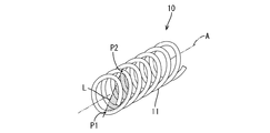
P1…始点
P2…終点
A…巻回軸
Claims (3)
- 平板状の端子と、
導電性の線材が巻回軸に対してらせん状に巻回されており、その巻回軸と前記端子が平行になるように配されて、前記端子と平板状の相手端子との間に挟み込まれる斜め巻きコイルスプリングと、
前記端子と前記斜め巻きコイルスプリングを収容すると共に、前記相手端子を前記端子と平行になるように挿入させる挿入路を有するコネクタハウジングと、
前記コネクタハウジングに設けられ、前記斜め巻きコイルスプリングをその半周分の前記線材とその半周分の始点と終点とを結んだ直線によって定義される半周巻回面が、前記相手端子側がその挿入方向奥側となり前記端子側が前記相手端子の挿入方向手前側になるように前記巻回軸に対して傾く回転姿勢に規制する回転規制部とを備えたコネクタ。 - 前記コネクタハウジングには前記斜め巻きコイルスプリングを収容するバネ収容部が設けられ、
前記端子と前記バネ収容部の内壁のうち前記端子と対向する部分との間の対向寸法を、その対向方向と直交する方向における前記斜め巻きコイルスプリングの外径寸法よりも小さくすることで前記回転規制部が構成されている請求項1に記載のコネクタ。 - 前記バネ収容部には、前記斜め巻きコイルスプリングの前記巻回軸に沿って設けられ、前記斜め巻きコイルスプリング内に挿入された軸部が設けられている請求項2に記載のコネクタ。
Priority Applications (5)
| Application Number | Priority Date | Filing Date | Title |
|---|---|---|---|
| JP2016134119A JP6627664B2 (ja) | 2016-07-06 | 2016-07-06 | コネクタ |
| PCT/JP2017/022642 WO2018008382A1 (ja) | 2016-07-06 | 2017-06-20 | コネクタ |
| DE112017003434.5T DE112017003434T5 (de) | 2016-07-06 | 2017-06-20 | Verbinder |
| US16/314,695 US10644426B2 (en) | 2016-07-06 | 2017-06-20 | Connector |
| CN201780039850.4A CN109417239B (zh) | 2016-07-06 | 2017-06-20 | 连接器 |
Applications Claiming Priority (1)
| Application Number | Priority Date | Filing Date | Title |
|---|---|---|---|
| JP2016134119A JP6627664B2 (ja) | 2016-07-06 | 2016-07-06 | コネクタ |
Publications (2)
| Publication Number | Publication Date |
|---|---|
| JP2018006243A JP2018006243A (ja) | 2018-01-11 |
| JP6627664B2 true JP6627664B2 (ja) | 2020-01-08 |
Family
ID=60912730
Family Applications (1)
| Application Number | Title | Priority Date | Filing Date |
|---|---|---|---|
| JP2016134119A Active JP6627664B2 (ja) | 2016-07-06 | 2016-07-06 | コネクタ |
Country Status (5)
| Country | Link |
|---|---|
| US (1) | US10644426B2 (ja) |
| JP (1) | JP6627664B2 (ja) |
| CN (1) | CN109417239B (ja) |
| DE (1) | DE112017003434T5 (ja) |
| WO (1) | WO2018008382A1 (ja) |
Families Citing this family (2)
| Publication number | Priority date | Publication date | Assignee | Title |
|---|---|---|---|---|
| JP7077875B2 (ja) * | 2018-08-30 | 2022-05-31 | 株式会社デンソー | 電気接続コネクタ |
| EP4439870A1 (en) * | 2023-03-27 | 2024-10-02 | Hypertac S.p.a. | Female contact with at least one new wire assembly |
Family Cites Families (22)
| Publication number | Priority date | Publication date | Assignee | Title |
|---|---|---|---|---|
| US2882514A (en) * | 1955-10-11 | 1959-04-14 | Bell Telephone Labor Inc | Electric circuit connector |
| US3614296A (en) * | 1969-12-24 | 1971-10-19 | John H Blomstrand | Wire connector with frustoconical gripping spring |
| US4462657A (en) * | 1980-04-18 | 1984-07-31 | Eaton Corporation | Compliant electrical connector for flat conductors |
| JPS56174480U (ja) * | 1980-05-27 | 1981-12-23 | ||
| US4632496A (en) * | 1983-09-26 | 1986-12-30 | Williams Robert A | Connector socket |
| JP3076977B2 (ja) * | 1997-07-22 | 2000-08-14 | 日本航空電子工業株式会社 | 電気接続部材 |
| US7316593B2 (en) * | 2005-05-19 | 2008-01-08 | Bal Seal Engineering Co., Inc. | Electrical connector with embedded canted coil spring |
| US7429199B2 (en) * | 2005-08-12 | 2008-09-30 | Burgess James P | Low resistance, low insertion force electrical connector |
| JP4449988B2 (ja) | 2007-02-16 | 2010-04-14 | 三菱電機株式会社 | 接触子装置 |
| EP2267846B1 (en) * | 2008-04-14 | 2014-11-19 | Mitsubishi Electric Corporation | Contactor |
| US20100279558A1 (en) * | 2009-04-29 | 2010-11-04 | Gordon Leon | Electrical contact assemblies with canted coil springs |
| WO2011017432A1 (en) * | 2009-08-05 | 2011-02-10 | Medtronic, Inc. | Connector and contact assemblies for medical devices |
| WO2011034959A2 (en) * | 2009-09-15 | 2011-03-24 | Bal Seal Engineering, Inc. | Variable canted coil spring cross section |
| US8382533B2 (en) * | 2010-07-02 | 2013-02-26 | Lear Corporation | Electrically conducting terminal |
| US8282429B2 (en) * | 2010-07-02 | 2012-10-09 | Lear Corporation | Electrical terminal with coil spring |
| DE202010010827U1 (de) * | 2010-07-29 | 2010-10-21 | Rosenberger Hochfrequenztechnik Gmbh & Co. Kg | Hochstromsteckverbinder |
| US8844126B2 (en) * | 2010-12-23 | 2014-09-30 | Bal Seal Engineering, Inc. | Method of manufacturing an electrical connector |
| US8735751B2 (en) * | 2011-04-26 | 2014-05-27 | Bal Seal Engineering, Inc. | Varying diameter canted coil spring contacts and related methods of forming |
| CN103688416A (zh) * | 2011-05-06 | 2014-03-26 | 安德雷斯·维格 | 电接触元件 |
| JP5782298B2 (ja) * | 2011-05-31 | 2015-09-24 | 住友電気工業株式会社 | 斜め巻きばね及び斜め巻きばね用線材 |
| JP6271924B2 (ja) * | 2013-09-17 | 2018-01-31 | Necプラットフォームズ株式会社 | コネクタ装置、及び、接続方法 |
| JP6340666B2 (ja) * | 2014-08-25 | 2018-06-13 | 北川工業株式会社 | 導電部材 |
-
2016
- 2016-07-06 JP JP2016134119A patent/JP6627664B2/ja active Active
-
2017
- 2017-06-20 US US16/314,695 patent/US10644426B2/en active Active
- 2017-06-20 CN CN201780039850.4A patent/CN109417239B/zh active Active
- 2017-06-20 WO PCT/JP2017/022642 patent/WO2018008382A1/ja not_active Ceased
- 2017-06-20 DE DE112017003434.5T patent/DE112017003434T5/de not_active Withdrawn
Also Published As
| Publication number | Publication date |
|---|---|
| CN109417239A (zh) | 2019-03-01 |
| US10644426B2 (en) | 2020-05-05 |
| JP2018006243A (ja) | 2018-01-11 |
| WO2018008382A1 (ja) | 2018-01-11 |
| DE112017003434T5 (de) | 2019-04-25 |
| CN109417239B (zh) | 2020-06-19 |
| US20190319387A1 (en) | 2019-10-17 |
Similar Documents
| Publication | Publication Date | Title |
|---|---|---|
| JP6183626B2 (ja) | フローティング機構付き同軸コネクタ | |
| CN101325291B (zh) | 扁平型导体用电连接器 | |
| JP4770983B2 (ja) | 同軸コネクタ | |
| JP6860836B2 (ja) | コネクタ | |
| JP5941515B2 (ja) | コネクタ | |
| US9583869B2 (en) | Connector and electrical connection device | |
| EP3547464A1 (en) | Elelctrical connector | |
| JP7402435B2 (ja) | 雌端子 | |
| US10622743B2 (en) | Terminal module with a conductive obliquely wound coil spring held against an electrical contact member and connector having such a terminal module | |
| WO2020017572A1 (ja) | コネクタ及び外導体 | |
| JP6627664B2 (ja) | コネクタ | |
| WO2017110466A1 (ja) | 端子金具及びコネクタ | |
| US10044141B2 (en) | Connector and electrical connection device | |
| JP5660776B2 (ja) | コンタクト | |
| KR102871391B1 (ko) | 접속 단자 | |
| CN110911873B (zh) | 连接端子 | |
| JP6780513B2 (ja) | 端子モジュール | |
| JP6513480B2 (ja) | コネクタ | |
| JP5900544B2 (ja) | コネクタ端子 | |
| JP7318500B2 (ja) | 電気コネクタ及び電気コネクタの製造方法 | |
| JP5044507B2 (ja) | コネクタ | |
| JP2001351759A (ja) | ブラシホルダーアセンブリ | |
| CN120200051A (zh) | 连接器 | |
| JP4353775B2 (ja) | 小型モータの給電装置 | |
| WO2024004891A1 (ja) | コネクタ |
Legal Events
| Date | Code | Title | Description |
|---|---|---|---|
| A621 | Written request for application examination |
Free format text: JAPANESE INTERMEDIATE CODE: A621 Effective date: 20181029 |
|
| TRDD | Decision of grant or rejection written | ||
| A01 | Written decision to grant a patent or to grant a registration (utility model) |
Free format text: JAPANESE INTERMEDIATE CODE: A01 Effective date: 20191105 |
|
| A61 | First payment of annual fees (during grant procedure) |
Free format text: JAPANESE INTERMEDIATE CODE: A61 Effective date: 20191118 |
|
| R150 | Certificate of patent or registration of utility model |
Ref document number: 6627664 Country of ref document: JP Free format text: JAPANESE INTERMEDIATE CODE: R150 |
|
| R250 | Receipt of annual fees |
Free format text: JAPANESE INTERMEDIATE CODE: R250 |
|
| R250 | Receipt of annual fees |
Free format text: JAPANESE INTERMEDIATE CODE: R250 |