JP6619683B2 - Sheet lamination jig, method for producing laminated product, and method for producing sheet-shaped secondary battery - Google Patents

Sheet lamination jig, method for producing laminated product, and method for producing sheet-shaped secondary battery Download PDF

Info

Publication number
JP6619683B2
JP6619683B2 JP2016075641A JP2016075641A JP6619683B2 JP 6619683 B2 JP6619683 B2 JP 6619683B2 JP 2016075641 A JP2016075641 A JP 2016075641A JP 2016075641 A JP2016075641 A JP 2016075641A JP 6619683 B2 JP6619683 B2 JP 6619683B2
Authority
JP
Japan
Prior art keywords
sheet
holding
electrode
sheets
yoke
Prior art date
Legal status (The legal status is an assumption and is not a legal conclusion. Google has not performed a legal analysis and makes no representation as to the accuracy of the status listed.)
Expired - Fee Related
Application number
JP2016075641A
Other languages
Japanese (ja)
Other versions
JP2017185675A (en
JP2017185675A5 (en
Inventor
秀憲 安藤
秀憲 安藤
誠 菊田
誠 菊田
剛一 岩尾
剛一 岩尾
Current Assignee (The listed assignees may be inaccurate. Google has not performed a legal analysis and makes no representation or warranty as to the accuracy of the list.)
Micronics Japan Co Ltd
Original Assignee
Micronics Japan Co Ltd
Priority date (The priority date is an assumption and is not a legal conclusion. Google has not performed a legal analysis and makes no representation as to the accuracy of the date listed.)
Filing date
Publication date
Priority to JP2016075641A priority Critical patent/JP6619683B2/en
Application filed by Micronics Japan Co Ltd filed Critical Micronics Japan Co Ltd
Priority to US16/091,483 priority patent/US10707516B2/en
Priority to CN201780022118.6A priority patent/CN109075372A/en
Priority to EP17778932.8A priority patent/EP3442066B1/en
Priority to KR1020187031983A priority patent/KR102134531B1/en
Priority to CA3020073A priority patent/CA3020073A1/en
Priority to PCT/JP2017/010399 priority patent/WO2017175553A1/en
Priority to TW106111139A priority patent/TWI620364B/en
Publication of JP2017185675A publication Critical patent/JP2017185675A/en
Publication of JP2017185675A5 publication Critical patent/JP2017185675A5/ja
Application granted granted Critical
Publication of JP6619683B2 publication Critical patent/JP6619683B2/en
Expired - Fee Related legal-status Critical Current
Anticipated expiration legal-status Critical

Links

Images

Classifications

    • BPERFORMING OPERATIONS; TRANSPORTING
    • B32LAYERED PRODUCTS
    • B32BLAYERED PRODUCTS, i.e. PRODUCTS BUILT-UP OF STRATA OF FLAT OR NON-FLAT, e.g. CELLULAR OR HONEYCOMB, FORM
    • B32B41/00Arrangements for controlling or monitoring lamination processes; Safety arrangements
    • BPERFORMING OPERATIONS; TRANSPORTING
    • B32LAYERED PRODUCTS
    • B32BLAYERED PRODUCTS, i.e. PRODUCTS BUILT-UP OF STRATA OF FLAT OR NON-FLAT, e.g. CELLULAR OR HONEYCOMB, FORM
    • B32B37/00Methods or apparatus for laminating, e.g. by curing or by ultrasonic bonding
    • B32B37/14Methods or apparatus for laminating, e.g. by curing or by ultrasonic bonding characterised by the properties of the layers
    • B32B37/16Methods or apparatus for laminating, e.g. by curing or by ultrasonic bonding characterised by the properties of the layers with all layers existing as coherent layers before laminating
    • B32B37/18Methods or apparatus for laminating, e.g. by curing or by ultrasonic bonding characterised by the properties of the layers with all layers existing as coherent layers before laminating involving the assembly of discrete sheets or panels only
    • HELECTRICITY
    • H01ELECTRIC ELEMENTS
    • H01MPROCESSES OR MEANS, e.g. BATTERIES, FOR THE DIRECT CONVERSION OF CHEMICAL ENERGY INTO ELECTRICAL ENERGY
    • H01M10/00Secondary cells; Manufacture thereof
    • H01M10/04Construction or manufacture in general
    • H01M10/0404Machines for assembling batteries
    • HELECTRICITY
    • H01ELECTRIC ELEMENTS
    • H01MPROCESSES OR MEANS, e.g. BATTERIES, FOR THE DIRECT CONVERSION OF CHEMICAL ENERGY INTO ELECTRICAL ENERGY
    • H01M50/00Constructional details or processes of manufacture of the non-active parts of electrochemical cells other than fuel cells, e.g. hybrid cells
    • H01M50/40Separators; Membranes; Diaphragms; Spacing elements inside cells
    • H01M50/46Separators, membranes or diaphragms characterised by their combination with electrodes
    • BPERFORMING OPERATIONS; TRANSPORTING
    • B32LAYERED PRODUCTS
    • B32BLAYERED PRODUCTS, i.e. PRODUCTS BUILT-UP OF STRATA OF FLAT OR NON-FLAT, e.g. CELLULAR OR HONEYCOMB, FORM
    • B32B2457/00Electrical equipment
    • HELECTRICITY
    • H01ELECTRIC ELEMENTS
    • H01MPROCESSES OR MEANS, e.g. BATTERIES, FOR THE DIRECT CONVERSION OF CHEMICAL ENERGY INTO ELECTRICAL ENERGY
    • H01M10/00Secondary cells; Manufacture thereof
    • H01M10/04Construction or manufacture in general
    • H01M10/0413Large-sized flat cells or batteries for motive or stationary systems with plate-like electrodes
    • HELECTRICITY
    • H01ELECTRIC ELEMENTS
    • H01MPROCESSES OR MEANS, e.g. BATTERIES, FOR THE DIRECT CONVERSION OF CHEMICAL ENERGY INTO ELECTRICAL ENERGY
    • H01M10/00Secondary cells; Manufacture thereof
    • H01M10/04Construction or manufacture in general
    • H01M10/0436Small-sized flat cells or batteries for portable equipment
    • YGENERAL TAGGING OF NEW TECHNOLOGICAL DEVELOPMENTS; GENERAL TAGGING OF CROSS-SECTIONAL TECHNOLOGIES SPANNING OVER SEVERAL SECTIONS OF THE IPC; TECHNICAL SUBJECTS COVERED BY FORMER USPC CROSS-REFERENCE ART COLLECTIONS [XRACs] AND DIGESTS
    • Y02TECHNOLOGIES OR APPLICATIONS FOR MITIGATION OR ADAPTATION AGAINST CLIMATE CHANGE
    • Y02EREDUCTION OF GREENHOUSE GAS [GHG] EMISSIONS, RELATED TO ENERGY GENERATION, TRANSMISSION OR DISTRIBUTION
    • Y02E60/00Enabling technologies; Technologies with a potential or indirect contribution to GHG emissions mitigation
    • Y02E60/10Energy storage using batteries
    • YGENERAL TAGGING OF NEW TECHNOLOGICAL DEVELOPMENTS; GENERAL TAGGING OF CROSS-SECTIONAL TECHNOLOGIES SPANNING OVER SEVERAL SECTIONS OF THE IPC; TECHNICAL SUBJECTS COVERED BY FORMER USPC CROSS-REFERENCE ART COLLECTIONS [XRACs] AND DIGESTS
    • Y02TECHNOLOGIES OR APPLICATIONS FOR MITIGATION OR ADAPTATION AGAINST CLIMATE CHANGE
    • Y02PCLIMATE CHANGE MITIGATION TECHNOLOGIES IN THE PRODUCTION OR PROCESSING OF GOODS
    • Y02P70/00Climate change mitigation technologies in the production process for final industrial or consumer products
    • Y02P70/50Manufacturing or production processes characterised by the final manufactured product

Description

本発明は、複数のシート間に部品が挿入された積層製品を製造する技術に関する。   The present invention relates to a technique for manufacturing a laminated product in which components are inserted between a plurality of sheets.

特許文献1には、正極箔と、負極箔と、セパレータとを交互に積層する積層装置が開示されている。特許文献1の積層装置は、積層台と、積層台に正極箔、負極箔、及びセパレータなどのシート体を吸着搬送する搬送装置と、シート体を保持する保持機構を備えている。   Patent Document 1 discloses a laminating apparatus that alternately laminates positive foils, negative foils, and separators. The lamination apparatus of Patent Document 1 includes a lamination table, a conveyance device that adsorbs and conveys a sheet body such as a positive foil, a negative electrode foil, and a separator to the lamination table, and a holding mechanism that holds the sheet body.

特開2014−78464号公報JP 2014-78464 A

特許文献1では、搬送装置により、正極箔、負極箔、セパレータを積層装置に搬送している。例えば、セパレータ積層工程では、搬送装置がセパレータを積層装置まで搬送する。そして、保持機構を退避位置に移動して、セパレータが積層される。セパレータ積層工程が終わり、負極箔積層工程になると、搬送装置が負極箔を吸着保持して、積層装置に搬送する。そして、保持機構を退避位置に移動して、負極箔が積層される。   In Patent Document 1, a positive foil, a negative foil, and a separator are conveyed to a laminating apparatus by a conveying device. For example, in the separator stacking step, the transport device transports the separator to the stacking device. Then, the separator is stacked by moving the holding mechanism to the retracted position. When the separator laminating step is finished and the negative electrode foil laminating step is started, the conveying device sucks and holds the negative electrode foil and conveys it to the laminating device. Then, the holding mechanism is moved to the retracted position, and the negative electrode foil is laminated.

しかしながら、特許文献1では、積層工程毎に、搬送装置がシート体を搬送する必要が生じてしまうという問題がある。すなわち、1枚毎に、シート体をピック&プレース作業が必要となり、製造時間が長くなってしまう。特に積層枚数が多いほど、搬送に必要な合計時間が長くなり、生産性が低下してしまう。   However, in patent document 1, there exists a problem that a conveyance apparatus will need to convey a sheet | seat body for every lamination process. That is, for each sheet, the sheet body needs to be picked and placed, and the manufacturing time becomes long. In particular, the greater the number of stacked layers, the longer the total time required for conveyance and the lower the productivity.

本発明は、上記の課題に鑑みてなされたものであり、積層された複数のシート間に部品が配置された積層製品を簡便に製造することができる技術を提供することを目的とする。   This invention is made | formed in view of said subject, and it aims at providing the technique which can manufacture simply the laminated product by which components are arrange | positioned between several laminated | stacked sheets.

本実施形態の一態様に係るシート積層治具は、積層された複数のシート間に部品が配置された積層製品を製造するためのシート積層治具であって、ステージと、複数のシートを保持するシート保持側面を有し、前記シート保持側面が前記ステージ上のワークスペースに向かうように前記ステージの上に配置されたシート保持部と、複数の部品を保持する部品保持側面を有し、前記部品保持側面が前記ワークスペースを介して前記シート保持側面と対向配置されるように、前記ステージの上に配置された部品保持部と、前記複数のシートを前記シート保持側面に沿って保持するシート保持ガイドと、前記複数の部品を前記部品保持側面に沿って保持する部品保持ガイドと、前記シート保持部に設けられ、前記複数のシートの端部において、前記複数のシート間に隙間を生じさせる磁力を発生させる磁気回路と、を備えたものである。
ものである。
A sheet stacking jig according to an aspect of the present embodiment is a sheet stacking jig for manufacturing a stacked product in which components are arranged between a plurality of stacked sheets, and holds a stage and a plurality of sheets. A sheet holding side that is disposed on the stage so that the sheet holding side faces a work space on the stage, and a component holding side that holds a plurality of parts, A component holding unit disposed on the stage so that a component holding side surface is disposed to face the sheet holding side surface via the work space, and a sheet that holds the plurality of sheets along the sheet holding side surface. A holding guide, a component holding guide for holding the plurality of components along the component holding side surface, and provided in the sheet holding portion, and at an end portion of the plurality of sheets, A magnetic circuit for generating magnetic force to cause the gap between the number of sheets, those provided with.
Is.

上記のシート積層治具において、前記シート保持側面に沿った前記複数のシートの内の一枚のシートを前記ワークスペースに向けて倒すよう、前記磁気回路の磁力によって前記複数のシート間に隙間が生じた状態で、前記一枚のシートを把持するシート把持部材をさらに備えていてもよい。   In the sheet stacking jig, a gap is formed between the plurality of sheets by the magnetic force of the magnetic circuit so that one of the plurality of sheets along the sheet holding side surface is tilted toward the work space. In the generated state, a sheet gripping member that grips the single sheet may be further provided.

上記のシート積層治具において、前記磁気回路は、第1の方向に並んで配置された複数の磁石であって、隣り合う磁石の同極同士が向かうように配置された複数の磁石と、前記各磁石の両端側に配置された第1継鉄と、前記各第1継鉄に対応する位置に配置された非磁性材と、前記磁石に対応する位置に配置された第2継鉄と、を有していてもよい。   In the above sheet stacking jig, the magnetic circuit is a plurality of magnets arranged side by side in a first direction, and a plurality of magnets arranged so that the same poles of adjacent magnets face each other, A first yoke disposed on both ends of each magnet; a nonmagnetic material disposed at a position corresponding to each first yoke; a second yoke disposed at a position corresponding to the magnet; You may have.

上記のシート積層治具において、前記複数の磁石が永久磁石であり、前記第2継鉄と前記非磁性材とが前記第1の方向に移動可能に設けられていてもよい。   In the sheet stacking jig, the plurality of magnets may be permanent magnets, and the second yoke and the nonmagnetic material may be provided to be movable in the first direction.

上記のシート積層治具において、前記第1の方向が前記シート保持側面に沿った方向であり、3つ以上の前記永久磁石が前記第1の方向に並んで配置されており、前記第1の方向において、前記シート保持側面の一端部に配置された前記永久磁石の磁力より、前記シート保持側面の中央部分、及び前記シート保持側面の他端部に配置された前記永久磁石の磁力が弱くなっていてもよい。   In the sheet stacking jig, the first direction is a direction along the sheet holding side surface, and three or more permanent magnets are arranged side by side in the first direction. In the direction, the magnetic force of the permanent magnet disposed at the center portion of the sheet holding side surface and the other end portion of the sheet holding side surface is weaker than the magnetic force of the permanent magnet disposed at one end portion of the sheet holding side surface. It may be.

上記のシート積層治具において、前記複数の磁石が電磁石であってもよい。   In the sheet stacking jig, the plurality of magnets may be electromagnets.

上記のシート積層治具において、3つ以上の前記電磁石が前記第1の方向に並んで配置されており、前記第1の方向が前記シート保持側面に沿った方向であり、前記第1の方向において、前記シート保持側面の端部に配置された前記電磁石の磁力より、前記前記シート保持側面の中央部分、及び前記シート保持側面の他端部に配置された前記電磁石の磁力の方が弱くなるように、前記電磁石に電流を流すようにしてもよい。   In the sheet stacking jig, three or more electromagnets are arranged side by side in the first direction, and the first direction is a direction along the sheet holding side surface, and the first direction In this case, the magnetic force of the electromagnet arranged at the central portion of the sheet holding side surface and the other end of the sheet holding side surface is weaker than the magnetic force of the electromagnet arranged at the end portion of the sheet holding side surface. Thus, a current may be passed through the electromagnet.

上記のシート積層治具において、前記部品保持側面に沿った保持された前記複数の部品と、前記部品保持側面との間に挿入される部品めくり部材をさらに備え、前記部品めくり部材の挿入方向に沿って、前記複数の部品が並んで配置されており、前記部品めくり部材が前記複数の部品の中からを部品を1つずつ前記ワークスペースに向けて倒していくようにしてもよい。請求項1〜7のいずれか1項に記載のシート積層治具。   In the above sheet stacking jig, the sheet stacking jig further includes a component turning member inserted between the plurality of components held along the component holding side surface and the component holding side surface, and the component turning member is inserted in the insertion direction of the component turning member. The plurality of components may be arranged side by side, and the component turning member may be configured to tilt the components one by one toward the workspace one by one from the plurality of components. The sheet | seat lamination jig | tool of any one of Claims 1-7.

上記のシート積層治具において、前記磁気回路は、永久磁石と、前記永久磁石の一端部側に配置された第1継鉄と、他端部側に配置された第2継鉄と、前記永久磁石の上端部側に配置された第1非磁性体と、下端部側に配置された第2非磁性体と、を有していてもよい。   In the sheet stacking jig, the magnetic circuit includes a permanent magnet, a first yoke disposed on one end side of the permanent magnet, a second yoke disposed on the other end side, and the permanent magnet. You may have the 1st nonmagnetic body arrange | positioned at the upper end part side of a magnet, and the 2nd nonmagnetic body arrange | positioned at the lower end part side.

上記のシート積層治具において、前記永久磁石は、前記シート保持側面の第1の方向に沿った回転軸を中心として回転可能であるようにしてもよい。   In the sheet stacking jig, the permanent magnet may be rotatable about a rotation axis along a first direction of the sheet holding side surface.

本実施形態の一態様に係る製造方法は、上記のシート積層治具を用いて、積層製品を製造する製造方法であって、前記ステージの上に、前記シート保持部と前記複数のシートとを設置する工程と、前記ワークスペースに配置された前記複数のシートを持ち上げることで、前記複数のシートを前記シート保持側面に沿って保持する工程と、前記ステージの上に、前記部品保持部と前記複数の部品とを設置する工程と、前記ワークスペースに配置された前記複数の部品を持ち上げることで、前記複数の部品を前記部品保持側面に沿って保持する工程と、前記磁気回路を用いて、前記複数のシートの端部において、前記複数のシート間に隙間を生じさせる工程と、前記複数のシート間に隙間を生じさせた状態で前記ワークスペースに向けて、前記複数のシートのうちの最表面のシートを倒した後、前記最表面のシートの上に前記複数の部品の内の1つ以上の部品を倒す工程と、を備えたものである。   The manufacturing method which concerns on 1 aspect of this embodiment is a manufacturing method which manufactures a laminated product using said sheet | seat lamination jig | tool, Comprising: On the said stage, the said sheet | seat holding part and said several sheet | seat are provided. A step of installing, a step of holding the plurality of sheets along the sheet holding side surface by lifting the plurality of sheets arranged in the workspace, and the component holding unit and the stage on the stage Using the magnetic circuit, a step of installing a plurality of components, a step of holding the plurality of components along the component holding side surface by lifting the plurality of components arranged in the workspace, A step of creating a gap between the plurality of sheets at an end portion of the plurality of sheets, and a step of forming the gap between the plurality of sheets toward the work space. After defeating the sheet on the uppermost surface of the sheet, in which and a step to defeat one or more parts of the plurality of parts on the sheet of the uppermost surface.

本実施形態の一態様に係る製造方法は、上記のシート積層治具を用いて、積層製品を製造する製造方法であって、前記永久磁石の一方の極を前記第1非磁性体、及び他方の極を前記第2非磁性体に対応する位置に配置させた状態で、前記シートを前記シート保持側面に保持する第1工程と、前記永久磁石を前記回転軸に沿って回転させて、前記永久磁石の一方の極を前記第1継鉄に対応する位置、及び他方の極を前記第2継鉄に対応する位置に移動させる第2工程と、を行うものである。     A manufacturing method according to an aspect of the present embodiment is a manufacturing method for manufacturing a laminated product using the sheet stacking jig described above, wherein one pole of the permanent magnet is connected to the first non-magnetic body and the other. In a state where the pole is disposed at a position corresponding to the second nonmagnetic material, the first step of holding the sheet on the sheet holding side surface, and rotating the permanent magnet along the rotation axis, A second step of moving one pole of the permanent magnet to a position corresponding to the first yoke and moving the other pole to a position corresponding to the second yoke.

上記の製造方法によって、シート状二次電池を製造するシート状二次電池の製造方法であって、前記シートが充電層を備える単位電池シートであり、前記部品が前記単位電池シートに接続される電極であるものである。   A sheet-like secondary battery manufacturing method for manufacturing a sheet-like secondary battery by the above-described manufacturing method, wherein the sheet is a unit battery sheet including a charging layer, and the component is connected to the unit battery sheet. It is an electrode.

本発明によれば、積層された複数のシート間に部品が配置された積層製品を簡便に製造することができる技術を提供することができる。   ADVANTAGE OF THE INVENTION According to this invention, the technique which can manufacture simply the laminated product by which components are arrange | positioned between several laminated | stacked sheets can be provided.

積層製品であるシート状二次電池の構成を模式的に示す平面図である。It is a top view which shows typically the structure of the sheet-like secondary battery which is a laminated product. 積層製品であるシート状二次電池の構成を模式的に示す側面断面図である。It is side surface sectional drawing which shows typically the structure of the sheet-like secondary battery which is a laminated product. 二次電池の構成を模式的に示す側面断面図である。It is side surface sectional drawing which shows the structure of a secondary battery typically. 磁気回路の基本構成を示す図である。It is a figure which shows the basic composition of a magnetic circuit. 実施の形態1にかかるシート積層治具の構成を示す斜視図である。FIG. 3 is a perspective view illustrating a configuration of a sheet stacking jig according to the first embodiment. 実施の形態1にかかるシート積層治具の構成を示す斜視図である。FIG. 3 is a perspective view illustrating a configuration of a sheet stacking jig according to the first embodiment. シート積層治具の要部を模式的に示す斜視図である。It is a perspective view which shows typically the principal part of a sheet | seat lamination jig | tool. シート載置状態を模式的に示す側面断面図である。It is side surface sectional drawing which shows a sheet | seat mounting state typically. シート保持状態を模式的に示す側面断面図である。It is side surface sectional drawing which shows a sheet | seat holding state typically. 電極載置状態を模式的に示す側面断面図である。It is side surface sectional drawing which shows an electrode mounting state typically. 電極保持状態を模式的に示す側面断面図である。It is side surface sectional drawing which shows an electrode holding state typically. シート保持状態から1枚のシートを倒す様子を模式的に示す側面断面図である。It is side surface sectional drawing which shows typically a mode that one sheet | seat is brought down from a sheet | seat holding state. 電極保持状態から1つの電極を倒す様子を模式的に示す側面断面図である。It is side surface sectional drawing which shows typically a mode that one electrode is brought down from an electrode holding state. シート保持部に設けられた磁気回路の構成を模式的に示す側面図である。It is a side view which shows typically the structure of the magnetic circuit provided in the sheet | seat holding | maintenance part. ワークスペース側から見た磁気回路の構成を模式的に示す図である。It is a figure which shows typically the structure of the magnetic circuit seen from the workspace side. 分離状態におけるシート保持部の構成を模式的に示す側面図である。。It is a side view which shows typically the structure of the sheet | seat holding | maintenance part in a isolation | separation state. . 非分離状態において、磁気回路が発生する磁力線を示す図である。It is a figure which shows the magnetic force line which a magnetic circuit generate | occur | produces in a non-separation state. 分離状態において、磁気回路が発生する磁力線を示す図である。It is a figure which shows the magnetic force line which a magnetic circuit generate | occur | produces in a separation state. 積層製品の製造方法を示すフローチャートである。It is a flowchart which shows the manufacturing method of a laminated product. 電極用パレットを移動する工程を説明するための図であるIt is a figure for demonstrating the process of moving the pallet for electrodes. 実施の形態2におけるシート積層治具の磁気回路の構成を示す図である。6 is a diagram illustrating a configuration of a magnetic circuit of a sheet stacking jig in Embodiment 2. FIG. 図4とは、異なる磁気回路の基本構成を模式的に示す図である。FIG. 4 is a diagram schematically showing a basic configuration of a different magnetic circuit. 図22に示す磁気回路での第1工程を説明するための図である。It is a figure for demonstrating the 1st process in the magnetic circuit shown in FIG. 図22に示す磁気回路での第2工程を説明するための図である。It is a figure for demonstrating the 2nd process in the magnetic circuit shown in FIG.

以下、本発明の実施形態の一例について図面を参照して説明する。以下の説明は、本発明の好適な実施形態を示すものであって、本発明の技術的範囲が以下の実施形態に限定されるものではない。   Hereinafter, an example of an embodiment of the present invention will be described with reference to the drawings. The following description shows preferred embodiments of the present invention, and the technical scope of the present invention is not limited to the following embodiments.

実施の形態1.
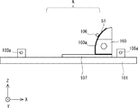
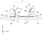
まず、本実施の形態にかかる製造方法による製造される積層製品の一例であるシート状二次電池の構成について、図1、図2を用いて説明する。図1は、シート状二次電池500の構成を示す平面図である。図2はシート状二次電池500の側面断面図である。
Embodiment 1 FIG.
First, the configuration of a sheet-like secondary battery that is an example of a laminated product manufactured by the manufacturing method according to the present embodiment will be described with reference to FIGS. 1 and 2. FIG. 1 is a plan view showing a configuration of a sheet-like secondary battery 500. FIG. 2 is a side sectional view of the sheet-like secondary battery 500.

シート状二次電池500は、複数のシート50と、複数の電極30とを有している。図2に示すように、複数のシート50は互いに積層されている。それぞれのシート50は、後述するように、充電層等を備える単位電池シートである。隣接する2枚のシート50の間に、電極30が挿入されている。すなわち、厚さ方向(図2の上下方向)において、シート50と電極30とが交互に配置されている。電極30は、図1における左右方向を長手方向とする帯状のシート電極となっている。   The sheet-like secondary battery 500 includes a plurality of sheets 50 and a plurality of electrodes 30. As shown in FIG. 2, the plurality of sheets 50 are stacked on each other. Each sheet 50 is a unit battery sheet including a charging layer and the like, as will be described later. The electrode 30 is inserted between the two adjacent sheets 50. That is, the sheets 50 and the electrodes 30 are alternately arranged in the thickness direction (vertical direction in FIG. 2). The electrode 30 is a belt-like sheet electrode whose longitudinal direction is the left-right direction in FIG.

平面視において、複数の電極30は、互いにずれて配置されており、櫛歯電極を構成している。すなわち、平面視において、複数の電極30が重ならないように配置されている。図1に示すように、平面視において、それぞれの電極30の一部がシート50からはみ出している。電極30のシート50からはみ出した部分がタブ部31となる。そして、複数の電極30のタブ部31同士をタブリード(不図示)等で接続することで、単位電池シートであるシート50同士が並列又は直列に接続される。   In the plan view, the plurality of electrodes 30 are arranged so as to be shifted from each other, and constitute a comb electrode. That is, the plurality of electrodes 30 are arranged so as not to overlap in a plan view. As shown in FIG. 1, a part of each electrode 30 protrudes from the sheet 50 in plan view. A portion of the electrode 30 that protrudes from the sheet 50 is a tab portion 31. Then, by connecting the tab portions 31 of the plurality of electrodes 30 with tab leads (not shown) or the like, the sheets 50 that are unit battery sheets are connected in parallel or in series.

各シート50は、例えば、100mm×100mmの大きさ、10μmの厚さを有している。図1では、6枚のシート50が積層されているが、シート50の積層数は特に限定されるものではない。例えば10枚のシート50を積み重ねることができる。シート50は、例えば、SUSシートなどの磁性体シートである。   Each sheet 50 has, for example, a size of 100 mm × 100 mm and a thickness of 10 μm. In FIG. 1, six sheets 50 are stacked, but the number of stacked sheets 50 is not particularly limited. For example, ten sheets 50 can be stacked. The sheet 50 is a magnetic sheet such as a SUS sheet, for example.

なお、図1、図2では、2つのシート50の間に1つの電極30が配置されている構成を示したが、シート50間に配置される電極30の数は、2以上であってもよい。すなわち、2つ以上の電極30をシート50間に配置してもよい。さらに、全てのシート50間に電極30を配置しなくてもよい。例えば、シート2枚毎に、あるいは3枚毎に電極30を配置してもよい。また、シート50間に配置される部品は電極30に限定されるものではない。例えば、絶縁材、接着材などのシート状の部品をシート50間に配置してもよい。   1 and 2 show a configuration in which one electrode 30 is disposed between two sheets 50, the number of electrodes 30 disposed between the sheets 50 may be two or more. Good. That is, two or more electrodes 30 may be disposed between the sheets 50. Furthermore, it is not necessary to arrange the electrodes 30 between all the sheets 50. For example, the electrodes 30 may be arranged every two sheets or every three sheets. Further, the parts arranged between the sheets 50 are not limited to the electrodes 30. For example, sheet-like components such as an insulating material and an adhesive material may be disposed between the sheets 50.

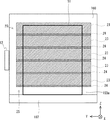
図3は、1枚のシート50に形成された電池構造を示す断面図である。シート50は、基材511上に、n型金属酸化物半導体層512、エネルギーを充電する充電層513、p型金属酸化物半導体層514、及び第2電極515がこの順序で積層された積層構造を有している。   FIG. 3 is a cross-sectional view showing a battery structure formed on one sheet 50. The sheet 50 has a stacked structure in which an n-type metal oxide semiconductor layer 512, a charge layer 513 for charging energy, a p-type metal oxide semiconductor layer 514, and a second electrode 515 are stacked in this order on a substrate 511. have.

基材511は金属などの導電性物質などにより形成され、第1電極として機能する。本実施形態では、基材511が負極となっている。基材511には、例えば、SUSシートなどの金属箔シートを用いることができる。   The base material 511 is formed of a conductive material such as metal and functions as a first electrode. In this embodiment, the base material 511 is a negative electrode. For the base material 511, for example, a metal foil sheet such as a SUS sheet can be used.

基材511の上には、n型金属酸化物半導体層512が形成されている。n型金属酸化物半導体層512の材料としては、例えば、二酸化チタン(TiO)を使用することが可能である。 An n-type metal oxide semiconductor layer 512 is formed over the base material 511. As a material of the n-type metal oxide semiconductor layer 512, for example, titanium dioxide (TiO 2 ) can be used.

充電層513の材料としては、微粒子のn型金属酸化物半導体を使用することが可能である。n型金属酸化物半導体は、紫外線照射により、充電機能を備えた層となる。充電層513は、n型金属酸化物半導体と絶縁性物質とを含む物質からなる。充電層513で使用可能なn型金属酸化物半導体材料としては、二酸化チタン、酸化スズ、酸化亜鉛が好適である。二酸化チタン、酸化スズ、及び酸化亜鉛のうちいずれか2つを組み合わせた材料、あるいは3つを組み合わせた材料を使用することが可能である。   As a material for the charge layer 513, a fine-particle n-type metal oxide semiconductor can be used. The n-type metal oxide semiconductor becomes a layer having a charging function when irradiated with ultraviolet rays. The charge layer 513 is made of a material containing an n-type metal oxide semiconductor and an insulating material. As the n-type metal oxide semiconductor material that can be used in the charge layer 513, titanium dioxide, tin oxide, and zinc oxide are suitable. It is possible to use a material combining any two of titanium dioxide, tin oxide, and zinc oxide, or a material combining three.

充電層513上には、p型金属酸化物半導体層514が形成されているp型金属酸化物半導体層514の材料としては、酸化ニッケル(NiO)、及び銅アルミ酸化物(CuAlO)等を使用することが可能である。 As the material of the p-type metal oxide semiconductor layer 514 on which the p-type metal oxide semiconductor layer 514 is formed on the charging layer 513, nickel oxide (NiO), copper aluminum oxide (CuAlO 2 ), or the like is used. It is possible to use.

p型金属酸化物半導体層514の上には、第2電極515が形成されている。第2電極515は正極となっている。第2電極515には、金属膜などの導電膜が用いられる。第2電極515として、CrとPdの積層膜、またはAl膜など抵抗を低くできる成膜を行う。また、第2電極としては、クロム(Cr)又は銅(Cu)等の金属電極を用いることができる。他の金属電極として、アルミニウム(Al)を含む銀(Ag)合金膜等がある。その形成方法としては、スパッタリング、イオンプレーティング、電子ビーム蒸着、真空蒸着、化学蒸着等の気相成膜法を挙げることができる。また、金属電極は電解メッキ法、無電解メッキ法等により形成することができる。メッキに使用される金属としては、一般に銅、銅合金、ニッケル、アルミ、銀、金、亜鉛又はスズ等を使用することが可能である。   A second electrode 515 is formed on the p-type metal oxide semiconductor layer 514. The second electrode 515 is a positive electrode. A conductive film such as a metal film is used for the second electrode 515. As the second electrode 515, a film that can reduce the resistance, such as a laminated film of Cr and Pd, or an Al film is formed. In addition, a metal electrode such as chromium (Cr) or copper (Cu) can be used as the second electrode. Examples of other metal electrodes include a silver (Ag) alloy film containing aluminum (Al). Examples of the forming method include vapor phase film forming methods such as sputtering, ion plating, electron beam evaporation, vacuum evaporation, and chemical vapor deposition. The metal electrode can be formed by an electrolytic plating method, an electroless plating method, or the like. In general, copper, copper alloy, nickel, aluminum, silver, gold, zinc, tin or the like can be used as a metal used for plating.

なお、本実施形態における基材511上の積層順は、反対でもよい。例えば、基材511を正極となる導電材料により形成し、第2電極515を負極としてもよい。この場合、n型金属酸化物半導体層512とp型金属酸化物半導体層514の位置を入れ替えればよい。すなわち、充電層513の下には、p型金属酸化物半導体層が配置され、上にはn型金属酸化物半導体層が配置されいてもよい。   Note that the order of stacking on the substrate 511 in this embodiment may be reversed. For example, the base material 511 may be formed using a conductive material that serves as a positive electrode, and the second electrode 515 may be used as a negative electrode. In this case, the positions of the n-type metal oxide semiconductor layer 512 and the p-type metal oxide semiconductor layer 514 may be interchanged. That is, a p-type metal oxide semiconductor layer may be disposed under the charging layer 513, and an n-type metal oxide semiconductor layer may be disposed thereon.

充電層513には、絶縁性物質とn型金属酸化物半導体とを混在した材料を用いている。以下、充電層513について詳細に説明する。充電層513は、絶縁性物質の材料として、シリコーンオイルを使用している。また、n型金属酸化物半導体の材料として、二酸化チタンを使用している。   The charge layer 513 is formed using a material in which an insulating material and an n-type metal oxide semiconductor are mixed. Hereinafter, the charge layer 513 will be described in detail. The charge layer 513 uses silicone oil as a material for the insulating substance. In addition, titanium dioxide is used as a material for the n-type metal oxide semiconductor.

充電層513に使用されるn型金属酸化物半導体の材料として、二酸化チタン、酸化スズ、酸化亜鉛を使用することが可能である。n型金属酸化物半導体は、これらの金属の脂肪族酸塩から製造工程で分解して生成される。このため、金属の脂肪族酸塩としては、酸化性雰囲気下で紫外線を照射すること、又は焼成することにより分解又は燃焼し、金属酸化物に変化しうるものが使用される。   As a material of the n-type metal oxide semiconductor used for the charging layer 513, titanium dioxide, tin oxide, or zinc oxide can be used. The n-type metal oxide semiconductor is produced by decomposition from an aliphatic acid salt of these metals in the manufacturing process. For this reason, as a metal aliphatic acid salt, what can be decomposed | disassembled or burned by irradiating an ultraviolet-ray in oxidizing atmosphere, or by baking, and can change into a metal oxide is used.

また、脂肪族酸塩は、加熱により分解又は燃焼しやすく、溶剤溶解性が高く、分解又は燃焼後の膜の組成が緻密であり、取り扱い易く安価であり、金属との塩の合成が容易である等の理由から、脂肪族酸と金属との塩が好ましい。   In addition, aliphatic acid salts are easy to decompose or burn by heating, have high solvent solubility, have a dense film composition after decomposition or combustion, are easy to handle and inexpensive, and are easy to synthesize salts with metals. For some reasons, a salt of an aliphatic acid and a metal is preferred.

そして、図3に示したシート50を単位電池シートとして、シート50を積層することで、シート状二次電池500の大容量化を図ることができる。例えば、複数のシート50を並列に接続する場合、第2電極515同士が向かい合うように2枚のシート50を積層して、シート50の間に電極30を挿入する。もちろん、基材511同士が向かい合うように2枚のシート50を積層して、複数のシート50を並列接続してもよい。このようにすることで、2つのシート50の同極同士が電極30で接続されるため、複数のシート50を並列に接続することができる。   And the sheet | seat 50 shown in FIG. 3 is used as a unit battery sheet, and the sheet | seat 50 can be increased in capacity | capacitance by laminating | stacking the sheet | seat 50. For example, when a plurality of sheets 50 are connected in parallel, two sheets 50 are stacked so that the second electrodes 515 face each other, and the electrode 30 is inserted between the sheets 50. Of course, two sheets 50 may be laminated so that the base materials 511 face each other, and a plurality of sheets 50 may be connected in parallel. By doing in this way, since the same polarity of the two sheets 50 is connected by the electrode 30, a plurality of sheets 50 can be connected in parallel.

また、複数のシート50を直列に接続する場合、第2電極515と基材511とが向かい合うように2枚のシート50を積層して、シート50の間に電極30を挿入する。このようにすることで、一方のシート50の第2電極515(正極)と他方のシート50の基材511(負極)とが接続されるため、複数のシートを直接に接続することができる。   When connecting a plurality of sheets 50 in series, the two sheets 50 are laminated so that the second electrode 515 and the substrate 511 face each other, and the electrode 30 is inserted between the sheets 50. By doing in this way, since the 2nd electrode 515 (positive electrode) of one sheet | seat 50 and the base material 511 (negative electrode) of the other sheet | seat 50 are connected, a some sheet | seat can be connected directly.

なお、図3では、基材511の一方の面にのみ、n型金属酸化物半導体層512、エネルギーを充電する充電層513、p型金属酸化物半導体層514、及び第2電極515が形成されているが、基材511の両面にn型金属酸化物半導体層512、充電層513、p型金属酸化物半導体層514、及び第2電極515が形成されていてもよい。   In FIG. 3, the n-type metal oxide semiconductor layer 512, the charge layer 513 for charging energy, the p-type metal oxide semiconductor layer 514, and the second electrode 515 are formed only on one surface of the base material 511. However, the n-type metal oxide semiconductor layer 512, the charge layer 513, the p-type metal oxide semiconductor layer 514, and the second electrode 515 may be formed on both surfaces of the base material 511.

上記したように、複数のシート50を積層し、シート50間に電極30を配置する。そして、電極30のタブ部31をタブリードで接続する。こうすることで、多数のシート50を並列又は直列に接続することができる。よって、複数のシート50が積層されたシート状二次電池500の大容量化を図ることができる。   As described above, the plurality of sheets 50 are stacked, and the electrode 30 is disposed between the sheets 50. And the tab part 31 of the electrode 30 is connected by a tab lead. By doing so, a large number of sheets 50 can be connected in parallel or in series. Therefore, the capacity of the sheet-like secondary battery 500 in which the plurality of sheets 50 are stacked can be increased.

本実施の形態では、シート状二次電池500の製造工程において、積層されたシート50間に電極30を配置するシート積層治具が用いられている。さらに、シート分離治具には、シートを分離するための磁気回路が設けられている。以下、シート分離治具を説明する前に、磁気回路の基本構成を説明する。   In the present embodiment, in the manufacturing process of the sheet-like secondary battery 500, a sheet stacking jig that arranges the electrodes 30 between the stacked sheets 50 is used. Further, the sheet separating jig is provided with a magnetic circuit for separating the sheets. Hereinafter, the basic configuration of the magnetic circuit will be described before describing the sheet separating jig.

図4は、磁気回路20の基本構成を示す図である。磁気回路20は、複数のシート50を分離するための磁力を発生するように配置される。具体的には、磁気回路20の上に複数のシート50が配置される。そして、磁気回路20が発生する磁力によって、複数のシート50の端部において、シート50間の隙間が大きくなる。   FIG. 4 is a diagram showing a basic configuration of the magnetic circuit 20. The magnetic circuit 20 is arranged so as to generate a magnetic force for separating the plurality of sheets 50. Specifically, a plurality of sheets 50 are arranged on the magnetic circuit 20. And the clearance gap between the sheets 50 becomes large in the edge part of the some sheet | seat 50 with the magnetic force which the magnetic circuit 20 generate | occur | produces.

磁気回路20は、永久磁石21と第1継鉄22と第2継鉄23と非磁性材24とを備えている。図4では、2つの永久磁石21がZ方向に並んで配置されている。ここで、2つの永久磁石21は同極同士が向かい合うように配置されている。図4では、2つの永久磁石21のS極同士が向かい合って配置されている。   The magnetic circuit 20 includes a permanent magnet 21, a first yoke 22, a second yoke 23, and a nonmagnetic material 24. In FIG. 4, two permanent magnets 21 are arranged side by side in the Z direction. Here, the two permanent magnets 21 are arranged so that the same poles face each other. In FIG. 4, the S poles of the two permanent magnets 21 are arranged to face each other.

磁気回路20は、2つの第1継鉄22を有している。2つの第1継鉄22は、左側の永久磁石21の両端に配置されている。よって、右側の第1継鉄22は、2つの永久磁石21の間に配置されている。2つの第1継鉄22は、右側の永久磁石21から左側の永久磁石21に向かう磁力線の向きを制御する。   The magnetic circuit 20 has two first yokes 22. The two first yokes 22 are arranged at both ends of the left permanent magnet 21. Therefore, the first yoke 22 on the right side is disposed between the two permanent magnets 21. The two first yokes 22 control the direction of the lines of magnetic force from the right permanent magnet 21 to the left permanent magnet 21.

磁気回路20は、3つの非磁性材24を有している。右側の非磁性材24と真ん中の非磁性材24が永久磁石21に対応する位置に配置される。換言すると、この2つの非磁性材24が、Z方向において、永久磁石21のN極とS極との間の中央位置(図4におけるN極とS極との間に点線)に配置される。つまり、非磁性材24は、Z方向における永久磁石21の中央位置に配置される。   The magnetic circuit 20 has three nonmagnetic materials 24. The right nonmagnetic material 24 and the middle nonmagnetic material 24 are disposed at positions corresponding to the permanent magnet 21. In other words, the two nonmagnetic materials 24 are arranged at a central position between the north pole and the south pole of the permanent magnet 21 in the Z direction (dotted line between the north pole and the south pole in FIG. 4). . That is, the nonmagnetic material 24 is disposed at the center position of the permanent magnet 21 in the Z direction.

また、第2継鉄23が第1継鉄22に対応する位置に配置される。Z方向における第2継鉄23の大きさは、第1継鉄22よりも大きくなっている。よって、右側の第2継鉄23は右側の第1継鉄22に対応する位置から左側の永久磁石21に対応する位置まで延在する。ここで、第2継鉄23のそれぞれは、永久磁石21の両極に対応する位置には、配置されない。   Further, the second yoke 23 is arranged at a position corresponding to the first yoke 22. The size of the second yoke 23 in the Z direction is larger than that of the first yoke 22. Therefore, the right second yoke 23 extends from a position corresponding to the right first yoke 22 to a position corresponding to the left permanent magnet 21. Here, each of the second yokes 23 is not disposed at a position corresponding to both poles of the permanent magnet 21.

すなわち、右の第2継鉄23は、右の第1継鉄22に対応する位置、及び左右の永久磁石21のS極に対応する位置のみに配置される。これにより、右側の第1継鉄22の両端に配置される永久磁石21の磁力が右側の第1継鉄22に集中し、更に、この集中した磁力が右側の第1継鉄22に接触している右側の第2継鉄23に集中する。   That is, the right second yoke 23 is disposed only at a position corresponding to the right first yoke 22 and a position corresponding to the S pole of the left and right permanent magnets 21. Thereby, the magnetic force of the permanent magnet 21 arranged at both ends of the right first yoke 22 is concentrated on the right first yoke 22, and this concentrated magnetic force is in contact with the right first yoke 22. Concentrate on the right second yoke 23.

この様に、磁気回路20で発生する磁力が特定方向に集中することにより、X方向における磁力線が大きくなり、第2継鉄23の表面を通って、シート50まで到達する。磁気回路20による磁力により、複数のシート50を反らせることができる。磁気回路20が発生させた磁力線Bの形は、放物線のようになっており、この放物線に沿ってシート50を反らせることができる。さらに、適切な磁力を発生して、シート50毎に反り量が変わるようにすることができる。これにより、シート50の端部において、シート50間の隙間を広くすることができる。よって、例えば、作業者がシート50の端部をピンセットなどで把持しやすくなるので、複数のシート50から1枚のシート50を容易に分離することができる。   As described above, the magnetic force generated in the magnetic circuit 20 is concentrated in a specific direction, so that the magnetic lines of force in the X direction increase and reach the sheet 50 through the surface of the second yoke 23. The plurality of sheets 50 can be warped by the magnetic force generated by the magnetic circuit 20. The shape of the magnetic lines of force B generated by the magnetic circuit 20 is a parabola, and the sheet 50 can be warped along the parabola. Furthermore, it is possible to generate an appropriate magnetic force so that the amount of warpage varies for each sheet 50. Thereby, the gap between the sheets 50 can be widened at the end of the sheet 50. Therefore, for example, the operator can easily grip the end of the sheet 50 with tweezers or the like, so that one sheet 50 can be easily separated from the plurality of sheets 50.

次に、本実施形態にかかるシート積層治具の構成について、図5〜図7を用いて説明する。図5、及び図6は、シート積層治具100の構成を示す斜視図である。図7は、シート積層治具100の一部の構成を省略して示す斜視図である。なお、図7では、積層された複数のシート50を積層体51として図示している。図5〜図7では、鉛直方向をZ方向、水平面をXY平面とするXYZ直交座標系を用いて説明する。   Next, the structure of the sheet | seat lamination jig | tool concerning this embodiment is demonstrated using FIGS. 5 and 6 are perspective views showing the configuration of the sheet stacking jig 100. FIG. FIG. 7 is a perspective view in which a part of the configuration of the sheet stacking jig 100 is omitted. In FIG. 7, a plurality of stacked sheets 50 are illustrated as a stacked body 51. 5 to 7, description will be made using an XYZ orthogonal coordinate system in which the vertical direction is the Z direction and the horizontal plane is the XY plane.

シート積層治具100は、ステージ101と、電極保持部102、電極保持ガイド103と、電極用パレット104、電極めくり棒105と、シート保持ガイド106、シート用パレット107、ピンセット108と、位置決めブロック109と、シート保持部160と、を備えている。   The sheet stacking jig 100 includes a stage 101, an electrode holding unit 102, an electrode holding guide 103, an electrode pallet 104, an electrode turning bar 105, a sheet holding guide 106, a sheet pallet 107, tweezers 108, and a positioning block 109. And a sheet holding unit 160.

ステージ101の上のある一定の領域が、複数のシート50を積層して、シート状二次電池500を製造するためのワークスペースAとなる。すなわち、ワークスペースAにおいて、シート50の上に電極30を配置する工程と、電極30の上にシート50を配置する工程とが交互に繰り返し行われる。これにより、図2に示したようなシート状二次電池500が製造される。なお、矩形状のシート50の端辺は、X方向、及びY方向に平行となっている。   A certain area on the stage 101 becomes a work space A for stacking a plurality of sheets 50 to manufacture the sheet-like secondary battery 500. That is, in the work space A, the step of arranging the electrode 30 on the sheet 50 and the step of arranging the sheet 50 on the electrode 30 are alternately and repeatedly performed. Thereby, the sheet-like secondary battery 500 as shown in FIG. 2 is manufactured. Note that the end sides of the rectangular sheet 50 are parallel to the X direction and the Y direction.

ステージ101の上には、電極保持部102とシート保持部160とが取り付けられている。電極保持部102とシート保持部160とは、ワークスペースAを介して対向配置されている。図5では、電極保持部102は、ワークスペースAの−X側に配置され、シート保持部160はワークスペースAの+X側に配置されている。このように、電極保持部102とシート保持ガイド106とは、X方向に離間して配置されている。   On the stage 101, an electrode holding unit 102 and a sheet holding unit 160 are attached. The electrode holding unit 102 and the sheet holding unit 160 are disposed to face each other with the work space A interposed therebetween. In FIG. 5, the electrode holding unit 102 is arranged on the −X side of the work space A, and the sheet holding unit 160 is arranged on the + X side of the work space A. As described above, the electrode holding unit 102 and the sheet holding guide 106 are arranged to be separated from each other in the X direction.

電極保持部102は、複数の電極30を保持する電極保持側面102aを有している。電極保持部102は、電極保持側面102aがワークスペースAに向かうように取り付けられている。すなわち、電極保持部102のワークスペースA側の側面が、電極保持側面102aとなる。図5では、電極保持側面102aに保持された電極30を電極30aとして、破線で示す。そして、シート状二次電池500を製造工程において、電極保持側面102aに保持された電極30aが1つずつ、ワークスペースAに配置されたシート50の上に倒される。こうすることで、シート50の上に電極30が配置される。なお、電極保持部102による電極30の保持動作については後述する。   The electrode holding unit 102 has an electrode holding side surface 102 a that holds the plurality of electrodes 30. The electrode holding portion 102 is attached so that the electrode holding side surface 102a faces the work space A. That is, the side surface on the work space A side of the electrode holding portion 102 becomes the electrode holding side surface 102a. In FIG. 5, the electrode 30 held on the electrode holding side surface 102a is indicated by a broken line as an electrode 30a. In the manufacturing process of the sheet-like secondary battery 500, the electrodes 30 a held on the electrode holding side surface 102 a are brought down one by one on the sheet 50 disposed in the work space A. By doing so, the electrode 30 is disposed on the sheet 50. The holding operation of the electrode 30 by the electrode holding unit 102 will be described later.

シート保持部160は、複数のシート50を保持するシート保持側面160aを有している。シート保持部160は、シート保持側面160aがワークスペースAを介して電極保持側面102aと対向配置されるように取り付けられている。すなわち、シート保持部160のワークスペースA側の側面が、シート保持側面160aとなる。図5、図6において、シート保持側面160aに保持されたシート50をシート50aとして示す。そして、シート状二次電池500を製造工程において、シート保持側面160aに保持されたシート50aが1枚ずつ、ワークスペースAに配置された電極30の上に倒される。こうすることで、電極30の上にシート50が配置される。なお、シート保持部160によるシート50の保持動作については後述する。   The sheet holding unit 160 has a sheet holding side surface 160 a that holds a plurality of sheets 50. The sheet holding unit 160 is attached so that the sheet holding side surface 160a is disposed to face the electrode holding side surface 102a with the work space A interposed therebetween. That is, the side surface on the work space A side of the sheet holding portion 160 becomes the sheet holding side surface 160a. 5 and 6, the sheet 50 held on the sheet holding side surface 160a is shown as a sheet 50a. In the manufacturing process of the sheet-like secondary battery 500, the sheets 50 a held on the sheet holding side surface 160 a are brought down one by one on the electrode 30 disposed in the work space A. By doing so, the sheet 50 is disposed on the electrode 30. The holding operation of the sheet 50 by the sheet holding unit 160 will be described later.

上記のように、ワークスペースAを挟んで、電極保持側面102aとシート保持側面160aとが向かい合うように配置されている。換言すると、ワークスペースAは電極保持側面102aとシート保持側面160aとの間に配置された領域となる。電極保持側面102aとシート保持側面160aとは、上側に行くほど、離れるように湾曲している。図5に示すように、電極保持側面102aは、上側(+Z方向側)に行くほど、−X側に位置するよう湾曲している。図6に示すように、シート保持側面160aは、上側に行くほど、+X側に位置するよう湾曲している。   As described above, the electrode holding side surface 102a and the sheet holding side surface 160a are arranged to face each other across the work space A. In other words, the work space A is an area disposed between the electrode holding side surface 102a and the sheet holding side surface 160a. The electrode holding side surface 102a and the sheet holding side surface 160a are curved so as to be separated from each other toward the upper side. As shown in FIG. 5, the electrode holding side surface 102a is curved so as to be positioned on the −X side as it goes upward (+ Z direction side). As shown in FIG. 6, the sheet holding side surface 160a is curved so as to be positioned on the + X side as it goes upward.

さらに、ステージ101とシート保持部160との間には、シート用パレット107が配置されている。シート用パレット107はシート50に対応する大きさの板状の部材である。シート用パレット107には、積層された複数のシート50が載置されている。そして、シート用パレット107の上に載置されたシート50の上に、シート保持部160が配置されている。シート保持部160は、シート50の+X側の端部の上に配置されている。すなわち、シート50、及びシート用パレット107は、シート保持部160から−X側にはみ出すように配置されている。シート用パレット107とシート保持部160とで、複数のシート50の一端を挟持している。   Further, a sheet pallet 107 is disposed between the stage 101 and the sheet holding unit 160. The sheet pallet 107 is a plate-like member having a size corresponding to the sheet 50. A plurality of stacked sheets 50 are placed on the sheet pallet 107. A sheet holding unit 160 is disposed on the sheet 50 placed on the sheet pallet 107. The sheet holding unit 160 is disposed on the + X side end of the sheet 50. That is, the sheet 50 and the sheet pallet 107 are arranged so as to protrude from the sheet holding unit 160 to the −X side. One end of the plurality of sheets 50 is held between the sheet pallet 107 and the sheet holding unit 160.

シート用パレット107は、矩形状の板状部材であり、その四隅近傍に位置決めブロック109が配置されている。図7に示すように、積層体51、及びシート用パレット107の角部が位置決めブロック109に当接するように配置される。このようにすることで、積層体51が所定の位置に配置される。   The sheet pallet 107 is a rectangular plate-like member, and positioning blocks 109 are arranged in the vicinity of the four corners thereof. As shown in FIG. 7, the laminated body 51 and the corners of the sheet pallet 107 are arranged so as to contact the positioning block 109. By doing in this way, the laminated body 51 is arrange | positioned in a predetermined position.

図5、図6に示すように、ステージ101には、回転軸106aを介して、シート保持ガイド106が取り付けられている。シート保持ガイド106は所望の形状に屈曲した棒状の金属又は樹脂によって形成されている。シート保持ガイド106は、回転軸106a周りに回転する。回転軸106aは、シート保持部160の+X側に配置されている。そして、シート保持ガイド106は、回転軸106aから、シート保持部160の−X側まで延びている。シート保持ガイド106の一部は、シート保持部160のシート保持側面160a側に配置される。   As shown in FIGS. 5 and 6, a sheet holding guide 106 is attached to the stage 101 via a rotation shaft 106 a. The sheet holding guide 106 is formed of a rod-shaped metal or resin bent into a desired shape. The sheet holding guide 106 rotates around the rotation shaft 106a. The rotation shaft 106 a is disposed on the + X side of the sheet holding unit 160. The sheet holding guide 106 extends from the rotation shaft 106 a to the −X side of the sheet holding unit 160. A part of the sheet holding guide 106 is disposed on the sheet holding side surface 160 a side of the sheet holding unit 160.

そして、シート保持ガイド106が、シート用パレット107上に配置されたシート50を持ち上げることで、複数のシート50がシート保持側面160aに沿って保持される。シート保持側面160aは、湾曲しているため、シート50は湾曲して保持される。   Then, the sheet holding guide 106 lifts the sheet 50 arranged on the sheet pallet 107, whereby the plurality of sheets 50 are held along the sheet holding side surface 160a. Since the sheet holding side surface 160a is curved, the sheet 50 is held curved.

ここで、シート保持ガイド106によって、複数のシート50をシート保持側面160aに沿って保持する保持動作について、図8、図9を用いて説明する。図8はシート保持ガイド106がシート50を保持する前の状態(以下、シート載置状態とする)を模式的に示す側面断面図である。すなわち、シート載置状態では、積層体51がシート用パレット107の上に載置されている。図9はシート保持部160とシート保持ガイド106とがシート50を保持した後の状態(以下、シート保持状態とする)を模式的に示す側面断面図である。なお、図8、図9では、積層された複数のシート50を積層体51として示している。また、図8、図9に示す状態では、電極保持部102等がステージ101に取り付けられていない。   Here, a holding operation for holding the plurality of sheets 50 along the sheet holding side surface 160a by the sheet holding guide 106 will be described with reference to FIGS. FIG. 8 is a side sectional view schematically showing a state before the sheet holding guide 106 holds the sheet 50 (hereinafter referred to as a sheet placement state). That is, in the sheet placement state, the stacked body 51 is placed on the sheet pallet 107. FIG. 9 is a side cross-sectional view schematically showing a state after the sheet holding unit 160 and the sheet holding guide 106 hold the sheet 50 (hereinafter referred to as a sheet holding state). In FIGS. 8 and 9, a plurality of stacked sheets 50 are shown as a stacked body 51. Further, in the state shown in FIGS. 8 and 9, the electrode holding portion 102 or the like is not attached to the stage 101.

図8に示すように、シート載置状態では、シート用パレット107の上に、積層体51の全体が載置されている。そして、積層体51の+X側の端部が、シート用パレット107とシート保持部160との間に配置されている。積層体51の下には、シート保持ガイド106が配置されている。すなわち、ワークスペースAにおいて、シート保持ガイド106は、シート用パレット107と積層体51との間に配置されている。積層体51は、シート保持ガイド106を乗り越えるように、シート用パレット107上に載置されている。そして、シート保持ガイド106を回転軸106a周りに回転させる。なお、図8では、Y方向に沿った回転軸106a周りに、シート保持ガイド106が回転動作する。ワークスペースAにおいて、シート保持ガイド106が矢印Bの方向に跳ね上げられる。   As shown in FIG. 8, the entire stacked body 51 is placed on the sheet pallet 107 in the sheet placement state. Then, the + X side end of the laminate 51 is disposed between the sheet pallet 107 and the sheet holding unit 160. A sheet holding guide 106 is disposed under the stacked body 51. That is, in the work space A, the sheet holding guide 106 is disposed between the sheet pallet 107 and the stacked body 51. The laminated body 51 is placed on a sheet pallet 107 so as to get over the sheet holding guide 106. Then, the sheet holding guide 106 is rotated around the rotation shaft 106a. In FIG. 8, the sheet holding guide 106 rotates around the rotation axis 106a along the Y direction. In the work space A, the sheet holding guide 106 is flipped up in the direction of arrow B.

これにより、ワークスペースAにおいて、シート保持ガイド106が上方向に移動して、図9に示すシート保持状態となる。図8に示したシート載置状態では、シート保持ガイド106は、積層体51の下側に配置されている。このため、シート保持ガイド106を矢印Bの方向に回転させると、シート保持ガイド106が積層体51を持ち上げる。そして、シート保持ガイド106がシート保持側面160aの近傍まで移動する。これにより、積層体51がシート保持部160のシート保持側面160aに沿った状態で保持される。すなわち、積層体51は、シート保持側面160aに沿った状態となり、シート保持側面160aとシート保持ガイド106との間で保持される。   As a result, in the work space A, the sheet holding guide 106 moves upward, and the sheet holding state shown in FIG. 9 is obtained. In the sheet placement state illustrated in FIG. 8, the sheet holding guide 106 is disposed below the stacked body 51. For this reason, when the sheet holding guide 106 is rotated in the direction of arrow B, the sheet holding guide 106 lifts the stacked body 51. Then, the sheet holding guide 106 moves to the vicinity of the sheet holding side surface 160a. Thereby, the stacked body 51 is held in a state along the sheet holding side surface 160 a of the sheet holding unit 160. That is, the stacked body 51 is in a state along the sheet holding side surface 160 a and is held between the sheet holding side surface 160 a and the sheet holding guide 106.

このように、シート保持ガイド106を動作させることで、シート載置状態と、シート保持状態とが切り替わる。すなわち、シート保持ガイド106を回転軸106a周りに回転させることで、積層体51をシート用パレット107から持ち上げた状態で保持することができる。シート保持状態では、積層体51がシート保持側面160aに沿った状態で保持される。すなわち、積層体51がシート保持側面160aとシート保持ガイド106との間に挟持される。このように、シート保持ガイド106は、ワークスペースAに配置された積層体51を持ち上げることで、積層体51をシート保持側面160aに沿って保持する。   As described above, by operating the sheet holding guide 106, the sheet placement state and the sheet holding state are switched. That is, by rotating the sheet holding guide 106 around the rotation shaft 106 a, the stacked body 51 can be held in a state where it is lifted from the sheet pallet 107. In the sheet holding state, the laminated body 51 is held in a state along the sheet holding side surface 160a. That is, the laminated body 51 is sandwiched between the sheet holding side surface 160 a and the sheet holding guide 106. In this way, the sheet holding guide 106 holds the laminated body 51 along the sheet holding side surface 160a by lifting the laminated body 51 arranged in the work space A.

図5〜図7の説明に戻る。ステージ101と電極保持部102との間には、電極用パレット104が配置されている。電極用パレット104の上には、電極30の−X側の端部が載置される板状の部材である(図7参照)。電極用パレット104の上には、電極30のタブ部31(図1、図2参照)が載置されることになる。すなわち、電極30は、電極保持部102から+X側にはみ出している。電極30の上には、電極保持部102が配置されている。したがって、電極用パレット104と電極保持部102とが電極30の一端を挟持している。   Returning to the description of FIGS. An electrode pallet 104 is disposed between the stage 101 and the electrode holder 102. On the electrode pallet 104, a plate-like member on which an end portion on the −X side of the electrode 30 is placed (see FIG. 7). On the electrode pallet 104, the tab portion 31 (see FIGS. 1 and 2) of the electrode 30 is placed. That is, the electrode 30 protrudes from the electrode holding portion 102 to the + X side. An electrode holding unit 102 is disposed on the electrode 30. Therefore, the electrode pallet 104 and the electrode holding portion 102 sandwich one end of the electrode 30.

電極30は、電極用パレット104の上から、シート用パレット107の上まで延在している。図7に示すように、電極用パレット104には、貫通穴104aが設けられている。また、ステージ101には、スライドピン101aが取り付けられている。さらに、ステージ101には、X方向に沿って長穴101bが設けられている。スライドピン101aは、長穴101b、及び貫通穴104aに、挿入されている。よって、スライドピン101aを長穴101bに沿ってスライド移動させることで、シート用パレット107がX方向に沿ってスライド移動する。なお、シート用パレット107のスライド移動については後述する。   The electrode 30 extends from the top of the electrode pallet 104 to the top of the sheet pallet 107. As shown in FIG. 7, the electrode pallet 104 is provided with a through hole 104a. In addition, a slide pin 101 a is attached to the stage 101. Further, the stage 101 is provided with a long hole 101b along the X direction. The slide pin 101a is inserted into the long hole 101b and the through hole 104a. Therefore, by sliding the slide pin 101a along the long hole 101b, the sheet pallet 107 slides along the X direction. The sliding movement of the sheet pallet 107 will be described later.

上記のように、電極保持部102は、ワークスペースAに向かって配置された電極保持側面102aを有している。電極保持側面102aに沿って、電極30aが保持される。電極保持側面102aは、溝102bを有している。溝102bは、Y方向に沿って形成されている。溝102bには、後述する電極めくり棒105が挿入される。したがって、電極めくり棒105は、電極30aと電極保持側面102aとの間に挿入される。   As described above, the electrode holding portion 102 has the electrode holding side surface 102a arranged toward the work space A. The electrode 30a is held along the electrode holding side surface 102a. The electrode holding side surface 102a has a groove 102b. The groove 102b is formed along the Y direction. An electrode turning rod 105 described later is inserted into the groove 102b. Therefore, the electrode turning bar 105 is inserted between the electrode 30a and the electrode holding side surface 102a.

ステージ101には、回転軸103aを介して、電極保持ガイド103が取り付けられている。電極保持ガイド103は、回転軸103a周りに回転する。回転軸103aは、電極保持部102の−X側に配置されている。そして、電極保持ガイド103は、回転軸103aから、電極保持部102の+X側まで延びている。電極保持ガイド103の一部は、電極保持部102の電極保持側面102a側に配置される。電極保持ガイド103は所望の形状(図5、図6ではコの字形状)に屈曲した棒状の金属又は樹脂によって形成されている。   An electrode holding guide 103 is attached to the stage 101 via a rotating shaft 103a. The electrode holding guide 103 rotates around the rotation shaft 103a. The rotation shaft 103 a is disposed on the −X side of the electrode holding unit 102. The electrode holding guide 103 extends from the rotating shaft 103a to the + X side of the electrode holding portion 102. A part of the electrode holding guide 103 is disposed on the electrode holding side surface 102 a side of the electrode holding portion 102. The electrode holding guide 103 is made of a rod-like metal or resin bent into a desired shape (a U-shape in FIGS. 5 and 6).

そして、電極保持部102が、ワークスペースAに配置された電極30を持ち上げることで、複数の電極30が電極保持側面102aに沿って保持される。電極保持側面102aは、湾曲しているため、電極30も湾曲して保持される。   And the electrode holding part 102 lifts the electrode 30 arrange | positioned in the work space A, and the some electrode 30 is hold | maintained along the electrode holding side surface 102a. Since the electrode holding side surface 102a is curved, the electrode 30 is also held curved.

ここで、電極保持ガイド103によって、複数の電極30を電極保持側面102aに沿って保持する保持動作について、図10、図11を用いて説明する。図10は電極保持ガイド103が電極30を保持する前の状態(以下、電極載置状態とする)を模式的に示す側面断面図である。図11は電極保持ガイド103が電極30を保持した後の状態(以下、電極保持状態とする)を模式的に示す側面断面図である。   Here, the holding operation of holding the plurality of electrodes 30 along the electrode holding side surface 102a by the electrode holding guide 103 will be described with reference to FIGS. FIG. 10 is a side sectional view schematically showing a state before the electrode holding guide 103 holds the electrode 30 (hereinafter referred to as an electrode mounting state). FIG. 11 is a side sectional view schematically showing a state after the electrode holding guide 103 holds the electrode 30 (hereinafter referred to as an electrode holding state).

図10に示すように、電極載置状態では、電極用パレット104の上に、電極30の一端(−X側の端部)が載置されている。さらに、電極30の他端(+X側の端部)はシート用パレット107の上に載置されている。電極30の下には、電極保持ガイド103が配置されている。すなわち、ワークスペースAにおいて、電極保持ガイド103は、ステージ101と電極30との間に配置されている。そして、電極保持ガイド103を回転軸103a周りに回転させる。なお、図10では、Y方向に沿った回転軸103a周りに、電極保持ガイド103が回転動作する。ワークスペースAにおいて、電極保持ガイド103が矢印Cの方向に跳ね上げられる。   As shown in FIG. 10, in the electrode placement state, one end (end on the −X side) of the electrode 30 is placed on the electrode pallet 104. Furthermore, the other end (the end on the + X side) of the electrode 30 is placed on the sheet pallet 107. An electrode holding guide 103 is disposed under the electrode 30. That is, in the work space A, the electrode holding guide 103 is disposed between the stage 101 and the electrode 30. Then, the electrode holding guide 103 is rotated around the rotation axis 103a. In FIG. 10, the electrode holding guide 103 rotates around the rotation axis 103a along the Y direction. In the workspace A, the electrode holding guide 103 is flipped up in the direction of arrow C.

これにより、ワークスペースAにおいて、電極保持ガイド103が上方向に移動して、図11に示す電極保持状態になる。図10に示した電極保持状態では、ワークスペースAにおいて、電極保持ガイド103は、電極30の下側に配置されている。このため、電極保持ガイド103を矢印Cの方向に回転させると、電極保持ガイド103が電極30を持ち上げる。そして、シート保持ガイド106がシート保持側面160aの近傍に移動する。これにより、電極30が電極保持部102の電極保持部102に沿った状態で保持される。すなわち、電極30は、電極保持部102に沿った状態となり、電極保持部102と電極保持ガイド103との間で保持される。   As a result, in the work space A, the electrode holding guide 103 moves upward, and the electrode holding state shown in FIG. 11 is obtained. In the electrode holding state illustrated in FIG. 10, the electrode holding guide 103 is disposed below the electrode 30 in the work space A. For this reason, when the electrode holding guide 103 is rotated in the direction of arrow C, the electrode holding guide 103 lifts the electrode 30. Then, the sheet holding guide 106 moves to the vicinity of the sheet holding side surface 160a. As a result, the electrode 30 is held in a state along the electrode holding portion 102 of the electrode holding portion 102. That is, the electrode 30 is in a state along the electrode holding portion 102 and is held between the electrode holding portion 102 and the electrode holding guide 103.

このように、電極保持ガイド103を回転動作させることで、電極載置状態と、電極保持状態とが切り替わる。すなわち、電極保持ガイド103を回転軸103a周りに回転させることで、シート用パレット107から電極30を持ち上げた状態で保持することができる。電極保持状態では、電極30が電極保持側面102aに沿った状態で保持される。すなわち、複数の電極30が電極保持側面102aと電極保持ガイド103との間に挟持される。   Thus, by rotating the electrode holding guide 103, the electrode mounting state and the electrode holding state are switched. That is, by rotating the electrode holding guide 103 around the rotation shaft 103a, the electrode 30 can be held in a state where it is lifted from the sheet pallet 107. In the electrode holding state, the electrode 30 is held in a state along the electrode holding side surface 102a. That is, the plurality of electrodes 30 are sandwiched between the electrode holding side surface 102 a and the electrode holding guide 103.

図11には、シート保持状態、かつ、電極保持状態の構成が示されている。すなわち、図11では、電極30が電極保持ガイド103によって跳ね上げられた状態となり、かつ、積層体51がシート保持ガイド106によって跳ね上げられた状態となっている。この状態から、シート50と電極30とを交互に倒していく。すなわち、1枚のシート50を倒す工程と、1枚の電極30を倒す工程とが交互に繰り返される。このようにすることで、図1、図2に示したシート状二次電池500が製造される。   FIG. 11 shows the configuration of the sheet holding state and the electrode holding state. That is, in FIG. 11, the electrode 30 is in a state of being flipped up by the electrode holding guide 103, and the stacked body 51 is in a state of being lifted up by the sheet holding guide 106. From this state, the sheet 50 and the electrode 30 are alternately tilted. That is, the process of defeating one sheet 50 and the process of depressing one electrode 30 are alternately repeated. By doing in this way, the sheet-like secondary battery 500 shown in FIG. 1, FIG. 2 is manufactured.

シート積層治具100は、電極めくり棒105、及びピンセット108を有している。ピンセット108は、1枚のシート50を把持するために設けられたシート把持部材の一例である。図6に示すように、ピンセット108が、シート保持部160に保持されたシート50aの端部を把持する。シート50aの端部を把持したピンセット108をワークスペースAに向けて操作することで、1枚のシート50aをめくることができる。具体的には、図12の矢印Dに示すように、ピンセット108を用いて1枚のシート50をシート保持ガイド106の下側に抜くことで、シート保持部160と電極保持ガイド103によるシート50の保持が解放される。これにより、1枚のシート50がシート用パレット107の上に倒される。このように、シート保持部160に保持されている積層体51から1枚のシート50を分離することで、ワークスペースAにおいて、シート50がシート用パレット107上に1枚ずつ配置される。   The sheet stacking jig 100 includes an electrode turning bar 105 and tweezers 108. The tweezers 108 is an example of a sheet gripping member provided for gripping one sheet 50. As shown in FIG. 6, the tweezers 108 grips the end portion of the sheet 50 a held by the sheet holding unit 160. By operating the tweezers 108 holding the end of the sheet 50a toward the work space A, one sheet 50a can be turned. Specifically, as shown by an arrow D in FIG. 12, by pulling out one sheet 50 to the lower side of the sheet holding guide 106 using the tweezers 108, the sheet 50 by the sheet holding unit 160 and the electrode holding guide 103 is used. Is released. As a result, one sheet 50 is brought down on the sheet pallet 107. In this manner, by separating one sheet 50 from the stacked body 51 held by the sheet holding unit 160, the sheets 50 are arranged one by one on the sheet pallet 107 in the work space A.

電極めくり棒105は、溝102bに挿入される。図11では、溝102bはY方向に沿って設けられているため、電極めくり棒105の挿入方向はY方向となっている。図5に示すように、電極めくり棒105は、電極30aと電極保持部102との間に挿入される。電極めくり棒105を電極保持側面102aから離すように操作する。具体的には、図13の矢印Eに示すように、電極めくり棒105を用いて1つの電極30を電極保持ガイド103の下側に抜くことで、電極30がシート用パレット107の上に倒される。これにより、電極保持部102と電極保持ガイド103による電極30の保持が解放される。したがって、電極30がワークスペースA上に配置されたシート50の上に配置される。   The electrode turning bar 105 is inserted into the groove 102b. In FIG. 11, since the groove 102b is provided along the Y direction, the insertion direction of the electrode turning bar 105 is the Y direction. As shown in FIG. 5, the electrode turning bar 105 is inserted between the electrode 30 a and the electrode holding portion 102. The electrode turning bar 105 is operated so as to be separated from the electrode holding side surface 102a. Specifically, as shown by an arrow E in FIG. 13, the electrode 30 is pulled down on the sheet pallet 107 by pulling one electrode 30 below the electrode holding guide 103 using the electrode turning bar 105. It is. Thereby, the holding of the electrode 30 by the electrode holding part 102 and the electrode holding guide 103 is released. Therefore, the electrode 30 is disposed on the sheet 50 disposed on the work space A.

ここで、電極めくり棒105が挿入される溝102bはY方向に沿って形成されている。さらに、図5に示したように、Y方向において、複数の電極30がずれて配置されている。したがって、電極めくり棒105が1つずつ電極30をめくることができる。すなわち、Y方向における電極めくり棒105の挿入位置を深めていくことで、電極めくり棒105が−Y側の電極30から1枚ずつ電極30をめくることができる。具体的には、まず、最も−Y側の電極30の位置まで電極めくり棒105を挿入して、1つ目の電極30の保持を解放する。次に、−Y側から2つ目の電極30の位置まで電極めくり棒105を挿入して、2つ目の電極30の保持を解放する。このように、溝102bに電極めくり棒105を徐々に深く挿入していくことで、−Y側から順番に1つずつ電極30の保持を解放することができる。   Here, the groove 102b into which the electrode turning bar 105 is inserted is formed along the Y direction. Further, as shown in FIG. 5, the plurality of electrodes 30 are shifted from each other in the Y direction. Therefore, the electrode turning bar 105 can turn the electrodes 30 one by one. That is, by deepening the insertion position of the electrode turning bar 105 in the Y direction, the electrode turning bar 105 can turn the electrodes 30 one by one from the −Y side electrode 30. Specifically, first, the electrode turning bar 105 is inserted to the position of the electrode 30 on the most −Y side, and the holding of the first electrode 30 is released. Next, the electrode turning bar 105 is inserted from the −Y side to the position of the second electrode 30 to release the holding of the second electrode 30. Thus, by gradually inserting the electrode turning bar 105 into the groove 102b, the holding of the electrodes 30 can be released one by one in order from the -Y side.

上記のように、ワークスペースAにシート50と電極30とを交互に配置していくことで、図1、図2に示したシート状二次電池500が製造される。ここで、シート保持状態において、積層体51から1枚のシート50をめくる場合、まず、図12に示すように、磁気回路20を使用して、積層体51からシート50を分離させる。これにより、シート保持ガイド106の上において、シート50間の隙間が広くしている(図12の破線の丸参照)。   As described above, the sheet-like secondary battery 500 shown in FIGS. 1 and 2 is manufactured by alternately arranging the sheets 50 and the electrodes 30 in the work space A. Here, when turning one sheet 50 from the laminated body 51 in the sheet holding state, first, as shown in FIG. 12, the magnetic circuit 20 is used to separate the sheet 50 from the laminated body 51. As a result, the gap between the sheets 50 is widened on the sheet holding guide 106 (see the dotted circle in FIG. 12).

シート保持部160は、積層体51から1枚のシート50を分離するための磁気回路20を有している。そして、シート保持部160は、磁気回路20の磁力を用いて、積層体51から1枚ずつシート50を分離する。以下、シート保持部160に設けられた磁気回路の構成について、図14、図15を用いて説明する。図14は、シート保持部160と磁気回路20の構成を模式的に示す側面図である。図15は、ワークスペースA側から見たシート保持部160と磁気回路20の構成を模式的に示す平面図である。   The sheet holding unit 160 includes a magnetic circuit 20 for separating one sheet 50 from the stacked body 51. Then, the sheet holding unit 160 separates the sheets 50 one by one from the stacked body 51 using the magnetic force of the magnetic circuit 20. Hereinafter, the configuration of the magnetic circuit provided in the sheet holding unit 160 will be described with reference to FIGS. 14 and 15. FIG. 14 is a side view schematically showing the configuration of the sheet holding unit 160 and the magnetic circuit 20. FIG. 15 is a plan view schematically showing the configuration of the sheet holding unit 160 and the magnetic circuit 20 as viewed from the work space A side.

なお、以下の説明において、図9、図10、図11、図14の様に、シート50を分離する前の積層体51の状態を「非分離状態」と言う。また、図12、図13、後述する図16の様に、シート50を分離した後の積層体51の状態を「分離状態」と言う。   In the following description, as shown in FIGS. 9, 10, 11, and 14, the state of the stacked body 51 before the sheet 50 is separated is referred to as a “non-separated state”. In addition, as shown in FIGS. 12 and 13 and FIG. 16 described later, the state of the laminated body 51 after the sheet 50 is separated is referred to as a “separated state”.

シート保持部160は、レバー12(図15参照)と、磁気回路20とを備えている。図2に示すように、シート保持部160は、+Y側のXZ平面に沿った側面には、レバー12が設けられている。レバー12は、後述するように、磁気回路20のスライド部25をZ方向に沿ってスライド移動するために設けられている。   The sheet holding unit 160 includes the lever 12 (see FIG. 15) and the magnetic circuit 20. As shown in FIG. 2, the sheet holding unit 160 is provided with a lever 12 on the side surface along the XZ plane on the + Y side. As will be described later, the lever 12 is provided to slide the slide portion 25 of the magnetic circuit 20 along the Z direction.

シート保持部160には、磁気回路20が収容されている。磁気回路20は、永久磁石21、第1継鉄22、及びスライド部25を備えている。スライド部25は、第2継鉄23と非磁性材24とを備えている。   The sheet holding unit 160 houses the magnetic circuit 20. The magnetic circuit 20 includes a permanent magnet 21, a first yoke 22, and a slide portion 25. The slide portion 25 includes a second yoke 23 and a nonmagnetic material 24.

磁気回路20は、複数の永久磁石21を有している。複数の永久磁石21は、シート保持側面160a内の第1の方向に並んで配置されている。図14、図15では、第1の方向として、Z方向が設定され、複数の永久磁石21がX方向に沿って配置されている。第1の方向は、Z方向に限定されない。。第1の方向として、シート保持側面160aに沿った方向を設定することができる。ここで「シート保持側面160aに沿った方向」には、上述のZ方向に加えて、Z方向から+Y側に傾いた方向やZ方向から−Y側に傾いた方向も含まれる。   The magnetic circuit 20 has a plurality of permanent magnets 21. The plurality of permanent magnets 21 are arranged side by side in the first direction in the sheet holding side surface 160a. 14 and 15, the Z direction is set as the first direction, and a plurality of permanent magnets 21 are arranged along the X direction. The first direction is not limited to the Z direction. . As the first direction, a direction along the sheet holding side surface 160a can be set. Here, the “direction along the sheet holding side surface 160a” includes, in addition to the Z direction described above, a direction inclined from the Z direction to the + Y side and a direction inclined from the Z direction to the −Y side.

また、複数の永久磁石21は、隣り合う磁石の同極同士が向かい合うように配置されている。図14に示されている例では、下から1番目と3番目の永久磁石21では、S極が+Z側、N極が−Z側に配置されている。一方、上から1番目3番目の永久磁石21では、N極が+Z側、S極が−Z側に配置されている。   Moreover, the some permanent magnet 21 is arrange | positioned so that the same pole of an adjacent magnet may face each other. In the example shown in FIG. 14, in the first and third permanent magnets 21 from the bottom, the S pole is arranged on the + Z side and the N pole is arranged on the −Z side. On the other hand, in the first and third permanent magnets 21 from the top, the N pole is arranged on the + Z side and the S pole is arranged on the −Z side.

このように配置することにより、上から1番目と2番目の永久磁石21が、S極同士が向かい合いように配置される。また、上から2番目と3番目の永久磁石21が、N極同士が向かい合いように配置される。また、上から、3番目と4番目の永久磁石21が、S極同士が向かい合うように配置される。   By arranging in this way, the first and second permanent magnets 21 from the top are arranged so that the south poles face each other. The second and third permanent magnets 21 from the top are arranged so that the N poles face each other. From the top, the third and fourth permanent magnets 21 are arranged so that the south poles face each other.

この様な配置を実現させる永久磁石21として、図14に示すような棒磁石を挙げることができるが、永久磁石21は棒磁石に限定されない。また、図14では、4つの永久磁石21が並んで配置されている例を示しているが、永久磁石21の数は特に限定されるものではない。上から1番目の永久磁石の磁力が一番強く、上から2〜4番目の永久磁石の磁力は1番目の永久磁石よりも弱くなるように設定してある。   As the permanent magnet 21 that realizes such an arrangement, a bar magnet as shown in FIG. 14 can be cited, but the permanent magnet 21 is not limited to a bar magnet. FIG. 14 shows an example in which four permanent magnets 21 are arranged side by side, but the number of permanent magnets 21 is not particularly limited. The magnetic force of the first permanent magnet from the top is the strongest, and the magnetic force of the second to fourth permanent magnets from the top is set to be weaker than that of the first permanent magnet.

各永久磁石21の両端側には、第1継鉄22が配置されている。すなわち、Z方向において、永久磁石21と第1継鉄22が交互に配置されている。図14では、5個の第1継鉄22がZ方向に沿って配置されている。第1継鉄22は、永久磁石21からの磁力線の向きを制御する。   First yokes 22 are arranged on both end sides of each permanent magnet 21. That is, the permanent magnets 21 and the first yokes 22 are alternately arranged in the Z direction. In FIG. 14, five first yokes 22 are arranged along the Z direction. The first yoke 22 controls the direction of the magnetic lines of force from the permanent magnet 21.

スライド部25は、永久磁石21の−X側に配置されている。すなわち、X方向において、永久磁石21と積層体51との間には、スライド部25が配置されている。スライド部25は、第2継鉄23と非磁性材24とを有している。第2継鉄23は、永久磁石21からの磁力線の流れを制御する。永久磁石21からの磁力線は、非磁性材24内を通過することはできない。   The slide portion 25 is disposed on the −X side of the permanent magnet 21. That is, the slide portion 25 is disposed between the permanent magnet 21 and the laminated body 51 in the X direction. The slide part 25 has a second yoke 23 and a nonmagnetic material 24. The second yoke 23 controls the flow of magnetic lines of force from the permanent magnet 21. The lines of magnetic force from the permanent magnet 21 cannot pass through the nonmagnetic material 24.

非磁性体24は、第1継鉄22に対応する位置に配置されている。また、第2継鉄23は、各永久磁石21に対応する位置に配置されている。Z方向において、非磁性材24と第2継鉄23とは、交互に配置されている。図14で示される例ではスライド部25は、5個の第2継鉄23と、5個の非磁性材24を有している。   The nonmagnetic body 24 is disposed at a position corresponding to the first yoke 22. The second yoke 23 is disposed at a position corresponding to each permanent magnet 21. In the Z direction, the nonmagnetic material 24 and the second yoke 23 are alternately arranged. In the example shown in FIG. 14, the slide portion 25 has five second yokes 23 and five nonmagnetic materials 24.

Z方向において、永久磁石21と第2継鉄23とはほぼ同じ大きさとなっている。Z方向において、永久磁石21と第2継鉄23とは同じ位置に配置されている。また、Z方向において、第1継鉄22と非磁性材24とはほぼ同じ大きさとなっている。また、Z方向において、第1継鉄22と非磁性材24とは同じ位置に配置されている。   In the Z direction, the permanent magnet 21 and the second yoke 23 are substantially the same size. In the Z direction, the permanent magnet 21 and the second yoke 23 are arranged at the same position. In the Z direction, the first yoke 22 and the nonmagnetic material 24 have substantially the same size. Moreover, the 1st yoke 22 and the nonmagnetic material 24 are arrange | positioned in the same position in the Z direction.

この様に、永久磁石21、第1継鉄22、第2継鉄23、及び非磁性材24を配置することで、永久磁石21から第1継鉄22を介した磁力が第2継鉄23に達しないように、及び永久磁石21から第2継鉄23を介した磁力が第1継鉄22に達しないようにすることができる。この様な図14で示されるスライド部25の配置を以下の説明で「初期状態」と言う。   In this manner, by arranging the permanent magnet 21, the first yoke 22, the second yoke 23, and the nonmagnetic material 24, the magnetic force from the permanent magnet 21 through the first yoke 22 can be increased. It is possible to prevent the magnetic force from the permanent magnet 21 via the second yoke 23 from reaching the first yoke 22. Such an arrangement of the slide part 25 shown in FIG. 14 is referred to as an “initial state” in the following description.

X方向において、永久磁石21と積層体51との間に、第2継鉄23が配置される。また、X方向において、第1継鉄22と積層体51との間に、非磁性材24が配置される。   The second yoke 23 is disposed between the permanent magnet 21 and the laminated body 51 in the X direction. Further, the nonmagnetic material 24 is disposed between the first yoke 22 and the laminated body 51 in the X direction.

図16は、分離状態における構成を模式的に示す側面断面図である。スライド部25は、シート保持部160に対してZ方向に移動可能に取り付けられている。すなわち、スライド部25は、シート保持部160内において、Z方向(第1の方向)にスライドする。具体的には、レバー12を操作することで、スライド部25がZ方向に沿ってスライドする。図16に、スライド部25をスライドした状態が示されている。この様な図16で示されるスライド部25の配置を以下の説明で「スライド状態」と言う。   FIG. 16 is a side cross-sectional view schematically showing the configuration in the separated state. The slide part 25 is attached to the sheet holding part 160 so as to be movable in the Z direction. That is, the slide unit 25 slides in the Z direction (first direction) within the sheet holding unit 160. Specifically, by operating the lever 12, the slide part 25 slides along the Z direction. FIG. 16 shows a state in which the slide unit 25 is slid. Such an arrangement of the slide portion 25 shown in FIG. 16 is referred to as a “slide state” in the following description.

レバー12を操作すると、図14に示す状態からスライド部25が−Z方向に移動する。つまり、スライド部25が「初期状態」から「スライド状態」に移動し、これにより、積層体51は図14に示す非分離状態から、図16に示す分離状態になる。   When the lever 12 is operated, the slide portion 25 moves in the −Z direction from the state shown in FIG. That is, the slide part 25 moves from the “initial state” to the “slide state”, whereby the stacked body 51 changes from the non-separated state shown in FIG. 14 to the separated state shown in FIG.

Z方向において、永久磁石21及び第1継鉄22に対する第2継鉄23、及び永久磁石21及び第1継鉄22に対する非磁性材24の相対位置が変化する。「初期状態」から「スライド状態」では、Z方向における永久磁石21と第1継鉄22との合計大きさのほぼ半分だけ、スライド部25が移動している。したがって、非磁性材24が永久磁石21に対応する位置に移動する。より具体的には、非磁性材24が永久磁石21に対応する位置に移動する。換言すると、非磁性材24が、Z方向において、永久磁石21のN極とS極との間の中央位置(図16におけるN極とS極との間に点線)の位置まで移動する。非磁性材24は、Z方向における永久磁石21の中央位置に配置される。   In the Z direction, the relative positions of the second yoke 23 with respect to the permanent magnet 21 and the first yoke 22 and the nonmagnetic material 24 with respect to the permanent magnet 21 and the first yoke 22 change. In the “sliding state” from the “initial state”, the sliding portion 25 is moved by almost half of the total size of the permanent magnet 21 and the first yoke 22 in the Z direction. Therefore, the nonmagnetic material 24 moves to a position corresponding to the permanent magnet 21. More specifically, the nonmagnetic material 24 moves to a position corresponding to the permanent magnet 21. In other words, the nonmagnetic material 24 moves in the Z direction to a central position between the north pole and the south pole of the permanent magnet 21 (a dotted line between the north pole and the south pole in FIG. 16). The nonmagnetic material 24 is disposed at the center position of the permanent magnet 21 in the Z direction.

また、第2継鉄23が第1継鉄22に対応する位置に移動する。Z方向における第2継鉄23の大きさは、第1継鉄22よりも大きくなっている。よって、第2継鉄23は第1継鉄22に対応する位置から永久磁石21に対応する位置まで延在する。ここで、第2継鉄23のそれぞれは、永久磁石21の両極に対応する位置には、配置されない。例えば、下から2番目の第2継鉄23は、第1継鉄22、及び永久磁石21のS極に対応する位置のみに位置する。下から3番目の第2継鉄23は、第1継鉄22、及び永久磁石21のN極に対応する位置のみに位置する。このように、第2継鉄23は、第1継鉄22に対応する位置から、永久磁石21の一方の磁極に対応する位置まで延在する。これにより、第1継鉄22の両端に配置される永久磁石21の磁力が第1継鉄22に集中し、更に、この集中した磁力が第1継鉄22に接触している第2継鉄23に集中する。   Further, the second yoke 23 moves to a position corresponding to the first yoke 22. The size of the second yoke 23 in the Z direction is larger than that of the first yoke 22. Therefore, the second yoke 23 extends from a position corresponding to the first yoke 22 to a position corresponding to the permanent magnet 21. Here, each of the second yokes 23 is not disposed at a position corresponding to both poles of the permanent magnet 21. For example, the second yoke 23 that is second from the bottom is located only at a position corresponding to the first yoke 22 and the south pole of the permanent magnet 21. The third second yoke 23 from the bottom is located only at the position corresponding to the first yoke 22 and the north pole of the permanent magnet 21. Thus, the second yoke 23 extends from a position corresponding to the first yoke 22 to a position corresponding to one magnetic pole of the permanent magnet 21. Thereby, the magnetic force of the permanent magnet 21 arrange | positioned at the both ends of the 1st yoke 22 concentrates on the 1st yoke 22, Furthermore, the 2nd yoke in which this concentrated magnetic force is contacting the 1st yoke 22 Concentrate on 23.

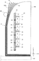
この様に、磁気回路20で発生する磁力が特定方向に集中することにより、X方向における磁力線が大きくなり、第2継鉄23の表面を通って、積層体51まで到達する。よって、磁気回路20による磁力により、積層体51を反らせることができる。ここで、図17、及び図18を用いて、磁気回路20において発生する磁力線について説明する。図17は、非分離状態での構成を示す側面図である。図18は、分離状態での構成を示す側面図である。すなわち、図17は、図14に示す非分離状態での磁力線Fを示し、図18は、図16に示す分離状態での磁力線Gを示している。   As described above, the magnetic force generated in the magnetic circuit 20 is concentrated in a specific direction, so that the magnetic lines of force in the X direction increase and reach the laminated body 51 through the surface of the second yoke 23. Therefore, the stacked body 51 can be warped by the magnetic force generated by the magnetic circuit 20. Here, the lines of magnetic force generated in the magnetic circuit 20 will be described with reference to FIGS. 17 and 18. FIG. 17 is a side view showing a configuration in a non-separated state. FIG. 18 is a side view showing the configuration in the separated state. That is, FIG. 17 shows the lines of magnetic force F in the non-separated state shown in FIG. 14, and FIG. 18 shows the lines of magnetic force G in the separated state shown in FIG.

図17では、1つの第2継鉄23が1つの永久磁石21のN極及びS極に対応する位置に配置されている。したがって、永久磁石21からの磁力線Fが第2継鉄23の内部を通る。すなわち、永久磁石21のN極から出た磁力線Fが第2継鉄23の内部を通って、永久磁石21のS極に戻る。したがって、スライド部25よりも−X側に磁力が生じない。よって、積層体51に磁力が与えられない。   In FIG. 17, one second yoke 23 is disposed at a position corresponding to the N pole and S pole of one permanent magnet 21. Accordingly, the magnetic field lines F from the permanent magnet 21 pass through the second yoke 23. That is, the lines of magnetic force F emitted from the north pole of the permanent magnet 21 pass through the second yoke 23 and return to the south pole of the permanent magnet 21. Therefore, no magnetic force is generated on the −X side from the slide portion 25. Therefore, no magnetic force is applied to the stacked body 51.

一方、図18では、1つの第2継鉄23が2つの永久磁石21の同極に対応する位置に配置されている。例えば、下から3番目の第2継鉄23は、下から2番目の永久磁石21のN極から、下から3番目の永久磁石21のN極に対応する位置に渡って形成されている。隣接する2つの第2継鉄23の間には、非磁性材24が配置されている。非磁性材24の内部を、磁力線Gが通過しない。したがって、永久磁石21のN極から延びる磁力線Gは、第2継鉄23の表面を通り抜ける。そして、磁力線Gは、非磁性材24の−X側の空間を通過して、永久磁石21のS極に戻る。磁力線Gは放物線のような軌道となる。したがって、磁力線Gがスライド部25を通過して積層体51に到達する。よって、積層体51に磁力が与えられる。   On the other hand, in FIG. 18, one second yoke 23 is disposed at a position corresponding to the same polarity of the two permanent magnets 21. For example, the third second yoke 23 from the bottom is formed from the N pole of the second permanent magnet 21 from the bottom to the position corresponding to the N pole of the third permanent magnet 21 from the bottom. A nonmagnetic material 24 is disposed between two adjacent second yokes 23. The lines of magnetic force G do not pass through the inside of the nonmagnetic material 24. Therefore, the magnetic field lines G extending from the N pole of the permanent magnet 21 pass through the surface of the second yoke 23. Then, the magnetic lines of force G pass through the space on the −X side of the nonmagnetic material 24 and return to the S pole of the permanent magnet 21. The magnetic field lines G have a trajectory like a parabola. Accordingly, the magnetic lines of force G pass through the slide portion 25 and reach the stacked body 51. Therefore, a magnetic force is applied to the stacked body 51.

また、磁気回路20において、3つ以上の永久磁石21がZ方向に並んで配置されている。そして、Z方向において、シート保持側面160aの上端部分に配置された永久磁石21の磁力より、シート保持側面160aの中央部分、及び下端部分に配置された永久磁石21の磁力の方が弱くなっている。   In the magnetic circuit 20, three or more permanent magnets 21 are arranged side by side in the Z direction. In the Z direction, the magnetic force of the permanent magnets 21 arranged at the central part and the lower part of the sheet holding side surface 160a is weaker than the magnetic force of the permanent magnet 21 arranged at the upper end portion of the sheet holding side surface 160a. Yes.

このように、3つ以上の永久磁石21が適切な磁力を発生するように設定することで、シート50の上端部に対する磁力がシート50の中央部分、及び下端部に対する磁力よりも強くなる。よって、複数のシート50を適切に反らせることができる。これにより、シート50の上端部において、シート50間の隙間を広くすることができるので、積層体51からシート50を容易に分離することができる。   As described above, by setting the three or more permanent magnets 21 to generate an appropriate magnetic force, the magnetic force on the upper end portion of the sheet 50 becomes stronger than the magnetic force on the central portion and the lower end portion of the sheet 50. Therefore, the plurality of sheets 50 can be appropriately warped. Thereby, since the gap between the sheets 50 can be widened at the upper end portion of the sheet 50, the sheet 50 can be easily separated from the stacked body 51.

このように、図16、図18に示すスライド状態(分離状態)では、積層体51に磁力が加わる。これにより、図16に示すように、積層体51がシート保持側面160aから離れるように、積層体51の反りが大きくなる。さらに、シート50毎に反り量が変わる。最も−X側のシート50は最も反り量が大きくなる。+X側のシート50ほど、反り量が小さくなる。したがって、積層体51の端部において、シート50間に隙間が生じる。これにより、積層体51からシート50が分離された「分離状態」となる。   Thus, in the sliding state (separated state) shown in FIGS. 16 and 18, magnetic force is applied to the stacked body 51. Thereby, as shown in FIG. 16, warpage of the stacked body 51 is increased so that the stacked body 51 is separated from the sheet holding side surface 160 a. Further, the amount of warpage changes for each sheet 50. The most -X side sheet 50 has the largest amount of warpage. The warp amount of the sheet 50 on the + X side decreases. Accordingly, a gap is generated between the sheets 50 at the end of the laminated body 51. As a result, a “separated state” in which the sheet 50 is separated from the laminate 51 is obtained.

「分離状態」になると、積層体51からシート50を一枚ずつ分離することができる。すなわち、ピンセット108によりシート50をめくる際に、2枚以上のシート50を一緒にめくることがなくなる。シート50の端部をピンセット108で挟みやすくなる。このように、シート保持部160の磁気回路20によって、容易に積層体51から1枚のシート50を分離することができる。よって、積層体51から簡単にシート50を1枚ずつ取ることができる。   In the “separated state”, the sheets 50 can be separated from the laminated body 51 one by one. That is, when turning the sheet 50 with the tweezers 108, two or more sheets 50 are not turned together. It becomes easy to pinch the end of the sheet 50 with the tweezers 108. As described above, the single sheet 50 can be easily separated from the stacked body 51 by the magnetic circuit 20 of the sheet holding unit 160. Therefore, the sheets 50 can be easily taken from the laminated body 51 one by one.

また、シート50の反り量は、特に1番上の永久磁石21(シート保持側面160aの上端部分に配置された永久磁石21)の磁力の強さを変更する等によって調整することができる。あるいは、第1継鉄22や第2継鉄23の大きさなどによって、磁力を調整することも可能である。また、スライド部25のスライド量によって、シート50の反り量を調整することも可能である。シート50が着磁しない程度の時間、及び磁力で処理することが好ましい。フェライト、ネオジムなどの永久磁石の種類により、磁力線の強弱があるが、原理として、磁石であれば、種類によらず使用可能である。   The amount of warpage of the sheet 50 can be adjusted by changing the strength of the magnetic force of the uppermost permanent magnet 21 (permanent magnet 21 disposed at the upper end portion of the sheet holding side surface 160a). Alternatively, the magnetic force can be adjusted depending on the size of the first yoke 22 and the second yoke 23. Further, the amount of warpage of the sheet 50 can be adjusted by the amount of slide of the slide portion 25. It is preferable to treat the sheet 50 with a time and magnetic force that do not cause the sheet 50 to be magnetized. Depending on the type of permanent magnets such as ferrite and neodymium, the magnetic field lines may be strong or weak, but in principle, any magnet can be used regardless of the type.

以下、本実施の形態にかかるシート積層治具100による効果について説明する。上記のように、ステージ101には、シート保持部160と電極保持部102とが対向配置されている。すなわち、本実施の形態では、シート50を吸着搬送する搬送装置、及びシート50を保持する保持機構等が必要ないので、装置全体を小型にすることができる。換言すると、本実施の形態では、装置の設置スペースを小さくすることができる。   Hereinafter, the effect by the sheet | seat lamination jig | tool 100 concerning this Embodiment is demonstrated. As described above, the sheet holding unit 160 and the electrode holding unit 102 are disposed opposite to each other on the stage 101. That is, in the present embodiment, since the conveying device that sucks and conveys the sheet 50, the holding mechanism that holds the sheet 50, and the like are not necessary, the entire apparatus can be reduced in size. In other words, in this embodiment, the installation space of the apparatus can be reduced.

さらに、シート保持部160、及び電極保持部102から交互にシート50、及び電極30をワークスペースAに倒すことで、シート50間に電極30が挿入された積層製品を製造している。このようにすることで、シート50をピック&プレースを行う機構を不要とすることができる。よって、少ない部品点数で製造することができる。これにより、積層製品を容易に製造することができる。   Furthermore, the laminated product in which the electrode 30 is inserted between the sheets 50 is manufactured by alternately tilting the sheet 50 and the electrode 30 from the sheet holding unit 160 and the electrode holding unit 102 to the work space A. In this way, a mechanism for picking and placing the sheet 50 can be eliminated. Therefore, it can be manufactured with a small number of parts. Thereby, a laminated product can be manufactured easily.

また、本実施の形態では、磁気回路20を用いて積層体51から1枚のシート50を分離している。このようにすることで、ピンセット108を使用して、積層体51の最表面から1枚のシート50を簡単に把持することができるので、シート50をワークスペースAに1枚ずつ容易に倒すことができる。   In the present embodiment, one sheet 50 is separated from the laminate 51 using the magnetic circuit 20. In this way, since one sheet 50 can be easily grasped from the outermost surface of the laminate 51 using the tweezers 108, the sheets 50 can be easily brought down to the work space A one by one. Can do.

また、本実施の形態では、複数のシート50が積層された積層体51をまとめて搬送することができる。したがって、1枚毎にシート50をピック&プレース作業を行う必要がなくなるため、生産性を向上することができる。これにより、積層された複数のシート間に部品が配置された積層製品を簡便に製造することができる。さらに、本実施の形態では、複数の電極30をまとめて搬送することができる。よって、生産性をより向上することができる。   Moreover, in this Embodiment, the laminated body 51 on which the some sheet | seat 50 was laminated | stacked can be conveyed collectively. Therefore, it is not necessary to perform the pick-and-place operation for each sheet 50, so that productivity can be improved. Thereby, the laminated product by which components are arrange | positioned between several laminated | stacked sheets can be manufactured simply. Further, in the present embodiment, a plurality of electrodes 30 can be transported together. Therefore, productivity can be further improved.

さらに、シート50の端部は、シート用パレット107とシート保持部160との間に挟持されている。また、電極30の端部は、電極用パレット104と電極保持部102との間に挟持されている。これにより、ワークスペースAに、シート50と電極30とを交互にワークスペースAに倒していく際に、シート50と電極30との位置ずれを防止させながら積層させることができる。また、積層された複数のシート50の端部を溶接などで接合して、位置ずれを防止してもよい。   Further, the end portion of the sheet 50 is sandwiched between the sheet pallet 107 and the sheet holding unit 160. The end of the electrode 30 is sandwiched between the electrode pallet 104 and the electrode holding part 102. Thereby, when the sheet 50 and the electrode 30 are alternately brought down to the work space A in the work space A, the sheets 50 and the electrode 30 can be stacked while preventing positional deviation. Further, the end portions of the plurality of stacked sheets 50 may be joined by welding or the like to prevent positional deviation.

次に、本実施の形態にかかるシート積層治具100を用いて、積層製品であるシート状二次電池500を製造する製造方法について、図19を用いて説明する。図19は、積層製品の製造方法を示すフローチャートである。   Next, the manufacturing method which manufactures the sheet-like secondary battery 500 which is a laminated product using the sheet | seat lamination jig | tool 100 concerning this Embodiment is demonstrated using FIG. FIG. 19 is a flowchart showing a method for manufacturing a laminated product.

まず、ステージ101の上に、積層体51、及びシート保持部160を設置する(S11)。すなわち、図8に示すように、積層体51が載置されたシート用パレット107、及びシート保持部160をステージ101に固定する。ここで、シート用パレット107は位置決めブロック109に当接するように、ステージ101に取り付けられている。これにより、シート載置状態となり、ワークスペースAに積層体51が配置される。   First, the laminated body 51 and the sheet holding unit 160 are installed on the stage 101 (S11). That is, as shown in FIG. 8, the sheet pallet 107 on which the laminated body 51 is placed and the sheet holding unit 160 are fixed to the stage 101. Here, the sheet pallet 107 is attached to the stage 101 so as to contact the positioning block 109. As a result, the sheet is placed and the laminate 51 is disposed in the work space A.

そして、シート保持ガイド106を用いて、積層体51をシート保持部160に保持する(S12)。すなわち、図8の矢印Bのように、シート保持ガイド106がワークスペースAに配置された積層体51を持ち上げる。こうすることで、シート保持状態となり、図9に示すように、積層体51がシート保持側面160aに沿って保持される。   Then, the laminate 51 is held on the sheet holding unit 160 using the sheet holding guide 106 (S12). That is, as indicated by an arrow B in FIG. 8, the sheet holding guide 106 lifts the stacked body 51 arranged in the work space A. By doing so, the sheet is held, and the laminate 51 is held along the sheet holding side surface 160a as shown in FIG.

次に、電極30、及び電極保持部102をステージ101の上に、設置する(S13)。すなわち、図10に示すように、複数の電極30が載置された電極用パレット104、及び電極保持部102をステージ101に固定する。これにより、電極載置状態となり、ワークスペースAに複数の電極30が配置される。ここでは、上記したように、図7に示すスライドピン101aが、電極用パレット104の貫通穴104aに挿入される。   Next, the electrode 30 and the electrode holding part 102 are installed on the stage 101 (S13). That is, as shown in FIG. 10, the electrode pallet 104 on which the plurality of electrodes 30 are placed and the electrode holding unit 102 are fixed to the stage 101. Thereby, it will be in an electrode mounting state and a plurality of electrodes 30 will be arranged in work space A. Here, as described above, the slide pin 101 a shown in FIG. 7 is inserted into the through hole 104 a of the electrode pallet 104.

そして、電極保持ガイド103を用いて、複数の電極30を電極保持部102に保持する(S14)。すなわち、図10の矢印Cのように、電極保持ガイド103がワークスペースAに配置された複数の電極30を持ち上げる。こうすることで、電極保持状態となり、図11に示すように、複数の電極30が電極保持側面102aに沿って保持される。   Then, the electrode holding guide 103 is used to hold the plurality of electrodes 30 on the electrode holding unit 102 (S14). That is, as indicated by an arrow C in FIG. 10, the electrode holding guide 103 lifts the plurality of electrodes 30 arranged in the work space A. By doing so, the electrode is held, and the plurality of electrodes 30 are held along the electrode holding side surface 102a as shown in FIG.

次に、シート保持部160とシート保持ガイド106との間に保持されている複数のシート50から1枚のシート50を分離する(S15)。すなわち、ユーザ又はモータがレバー12を回転させることで、スライド部25を初期状態からスライド状態に移動させる。これにより、複数のシート50が非分離状態から分離状態になる。   Next, one sheet 50 is separated from the plurality of sheets 50 held between the sheet holding unit 160 and the sheet holding guide 106 (S15). That is, the user or motor rotates the lever 12 to move the slide unit 25 from the initial state to the slide state. Thereby, the some sheet | seat 50 will be in a separation state from a non-separation state.

分離状態では、Z方向において、非磁性材24が永久磁石21の磁極間の位置に対応する位置とし、かつ第2継鉄23が第1継鉄22に対応する位置となっている。磁気回路20が発生する磁力が積層体51に加わる。よって、積層体51において、シート50同士の端部間に隙間が生じる。これにより、積層体51から1枚ずつシート50を容易に分離することができる。したがって、積層された複数のシート50は、図12、及び図16に示すように反った状態となる。   In the separated state, in the Z direction, the nonmagnetic material 24 is at a position corresponding to the position between the magnetic poles of the permanent magnet 21, and the second yoke 23 is at a position corresponding to the first yoke 22. Magnetic force generated by the magnetic circuit 20 is applied to the stacked body 51. Therefore, a gap is generated between the end portions of the sheets 50 in the stacked body 51. Accordingly, the sheets 50 can be easily separated from the stacked body 51 one by one. Therefore, the plurality of stacked sheets 50 are warped as shown in FIGS. 12 and 16.

非分離状態とは、詳細には積層体51のシート50のそれぞれがほぼ平行になっており、シート50間の隙間が狭くなった状態である。また、分離状態とは、詳細には、磁気回路20の磁力によって、積層体51のシート50のそれぞれが異なる角度に反っており、シート50間の隙間が広くなった状態である。積層体51を分離状態とすることで、積層体51からシート50を1枚ずつ容易に分離することができる。   Specifically, the non-separated state is a state in which each of the sheets 50 of the laminated body 51 is substantially parallel and a gap between the sheets 50 is narrowed. Further, in detail, the separated state is a state in which the sheets 50 of the stacked body 51 are warped at different angles by the magnetic force of the magnetic circuit 20, and the gap between the sheets 50 is widened. By setting the stacked body 51 in the separated state, the sheets 50 can be easily separated from the stacked body 51 one by one.

なお、ステップS11〜S15の順番は特に限定されるものではない。例えば、ステップS13、S14を実施した後、ステップS11、ステップS12を実施してもよい。さらに、ステップS15のシート50の分離工程は、積層体51を保持した後であれば、電極30の保持工程(ステップS13)よりも前に行ってもよい。   Note that the order of steps S11 to S15 is not particularly limited. For example, step S11 and step S12 may be performed after performing step S13 and S14. Furthermore, the separation process of the sheet 50 in step S15 may be performed before the electrode 30 holding process (step S13) as long as the laminated body 51 is held.

次に、シート50と電極30とを交互に倒していく(S16)。すなわち、シート50間に隙間が生じた状態でワークスペースAに向けて1枚のシート50を倒した後、シート50の上に1つの電極30を倒す。具体的には、ピンセット108、及び電極めくり棒105を用いて、1枚のシート50と1つの電極30をワークスペースAに向けて倒す。シート50を倒す場合、図12に示す矢印Dの方向に、シート50をめくる。こうすることで、積層体51から1枚のシート50を容易に分離することができる。1つの電極30を倒す場合、図13に示す矢印Eの方向に複数の電極30から1つの電極30をめくる。こうすることで、1つの電極30を容易に倒すことができる。   Next, the sheet 50 and the electrode 30 are alternately tilted (S16). That is, after one sheet 50 is tilted toward the work space A with a gap between the sheets 50, one electrode 30 is tilted on the sheet 50. Specifically, one sheet 50 and one electrode 30 are tilted toward the work space A using the tweezers 108 and the electrode turning bar 105. When the sheet 50 is tilted, the sheet 50 is turned in the direction of the arrow D shown in FIG. By doing so, one sheet 50 can be easily separated from the laminate 51. When one electrode 30 is tilted, one electrode 30 is turned from the plurality of electrodes 30 in the direction of arrow E shown in FIG. By doing so, one electrode 30 can be easily brought down.

なお、本実施の形態では、Z方向において、シート50と電極30とが交互に配置されている例を示している。つまり、シート50と電極30を交互に倒す例を説明している。しかしながら、シート50間に配置される電極30の数は1つではなく、設計に応じて変更することができる。   In the present embodiment, an example is shown in which the sheets 50 and the electrodes 30 are alternately arranged in the Z direction. That is, an example in which the sheet 50 and the electrode 30 are alternately tilted is described. However, the number of electrodes 30 arranged between the sheets 50 is not one, and can be changed according to the design.

例えば、2枚のシート50を倒す工程と、1つの電極30を倒す工程とを交互に行うようにしてもよい。この場合、一部のシート50間に電極30が配置されなくなる。   For example, the step of tilting two sheets 50 and the step of tilting one electrode 30 may be performed alternately. In this case, the electrode 30 is not disposed between some sheets 50.

また、反対に、1枚のシート50を倒す工程と、2つ以上の電極30を倒す工程を交互に行うようにしてもよい。この場合、シート50間に2つ以上の電極30を配置することができる。このように、シート状二次電池500の設計に応じて、シート50を倒す工程数と電極30を倒す工程数とを変更する。こうすることにより、シート50に挟まれる電極30の数を変更することができる。   On the contrary, the step of tilting one sheet 50 and the step of tilting two or more electrodes 30 may be performed alternately. In this case, two or more electrodes 30 can be disposed between the sheets 50. Thus, according to the design of the sheet-like secondary battery 500, the number of steps for tilting the sheet 50 and the number of steps for tilting the electrode 30 are changed. By doing so, the number of electrodes 30 sandwiched between the sheets 50 can be changed.

全てのシート50及び電極30を倒したら、電極用パレット104を移動する(S17)。これにより、電極用パレット104、及び電極保持部102がシート保持部160に近づくように移動される。具体的には、図7に示す状態から、スライドピン101aを長穴101bに沿ってスライド移動させる。これにより、図20に示す状態となる。スライドピン101aは、電極用パレット104、及び電極保持部102に挿入されているため、電極用パレット104、及び電極保持部102が+X方向に沿って移動する。したがって、電極30が+X方向に移動する。このようにすることで、シート50間に挟まれている電極30が所定の位置まで差し込まれる。つまり、電極30とシートとが所定の面積だけ重複する。なお、電極用パレット104をスライド移動する前に、電極用パレット104の移動の妨げにならないように、予め電極保持ガイド103を電極保持側面102aの前から移動してもよい。   When all the sheets 50 and the electrodes 30 are tilted, the electrode pallet 104 is moved (S17). Accordingly, the electrode pallet 104 and the electrode holding unit 102 are moved so as to approach the sheet holding unit 160. Specifically, the slide pin 101a is slid along the elongated hole 101b from the state shown in FIG. As a result, the state shown in FIG. 20 is obtained. Since the slide pin 101a is inserted into the electrode pallet 104 and the electrode holding part 102, the electrode pallet 104 and the electrode holding part 102 move along the + X direction. Therefore, the electrode 30 moves in the + X direction. By doing in this way, the electrode 30 pinched | interposed between the sheets 50 is inserted to a predetermined position. That is, the electrode 30 and the sheet overlap by a predetermined area. In addition, before the electrode pallet 104 is slid, the electrode holding guide 103 may be moved in advance from the front of the electrode holding side surface 102a so as not to hinder the movement of the electrode pallet 104.

さらに、図20に示すように、電極30に位置決め穴33が形成されていてもよい、位置決め穴33には、位置決めピン104bが挿入される。位置決めピン104bは、電極用パレット104に設けられている。これにより、電極30の端部は固定される。このため、電極用パレット104を移動した際に、電極30とシート50との摩擦で、電極30のシート50に対する位置ずれを防止することができる。したがって、電極用パレット104の移動により、所定の面積だけ電極30とシート50とを重複させ、所定の面積だけシート50からタブ部31をはみ出させることができる。   Furthermore, as shown in FIG. 20, the positioning pin 104b is inserted in the positioning hole 33 in which the positioning hole 33 may be formed in the electrode 30. The positioning pins 104b are provided on the electrode pallet 104. Thereby, the edge part of the electrode 30 is fixed. For this reason, when the electrode pallet 104 is moved, it is possible to prevent displacement of the electrode 30 with respect to the sheet 50 due to friction between the electrode 30 and the sheet 50. Therefore, by moving the electrode pallet 104, the electrode 30 and the sheet 50 can be overlapped by a predetermined area, and the tab portion 31 can be protruded from the sheet 50 by a predetermined area.

なお、上記の説明では、電極めくり棒105が、Y方向に並んで配置された電極30を1枚ずつめくることで、電極30を倒したが、電極を倒す方法は、これに限られるものではない。例えば、電極保持部102の−X側にエア噴出孔を配置することにより、電極30を倒すようしてもよい。具体的に、各電極30に対応させて、エア噴出孔、及びエアバルブを設ける。電極30とエア噴出孔とを1対1に対応させて配置させてもよい。あるいは、複数の電極30に対して1つのエア噴出孔を配置させてもよい。そして、複数のエアバルブを制御して、倒す電極30に対応したエア噴出孔からエアを噴出するようにしてもよい。エア噴出孔からのエアによって、電極30を1つずつ、又は複数ずつワークスペースAに向けて倒することができる。このようにすることで、電極30を倒す工程を容易に自動化することができる。   In the above description, the electrode turning rod 105 is turned over by turning the electrodes 30 arranged side by side in the Y direction one by one. However, the method of turning the electrodes is not limited to this. Absent. For example, the electrode 30 may be tilted by disposing an air ejection hole on the −X side of the electrode holding portion 102. Specifically, an air ejection hole and an air valve are provided corresponding to each electrode 30. The electrodes 30 and the air ejection holes may be arranged in a one-to-one correspondence. Alternatively, one air ejection hole may be arranged for the plurality of electrodes 30. Then, a plurality of air valves may be controlled so that air is ejected from the air ejection holes corresponding to the electrode 30 to be tilted. The electrodes 30 can be brought down toward the work space A one by one or plural by air from the air ejection holes. By doing in this way, the process of defeating the electrode 30 can be easily automated.

また、複数の電極30が、Y方向に並んで配置されるのではなく、複数の電極30が重なって保持されている場合もある。この場合、シート保持部160に収容されている磁気回路20と実質的に同様の磁気回路20を、電極保持側面102aに沿って電極保持部102内に収容する。そして、シート50と同様に、磁気回路の磁力により電極30を分離するようにしてもよい。この場合、電極30を磁性材料により形成する。   In addition, the plurality of electrodes 30 may not be arranged side by side in the Y direction, but the plurality of electrodes 30 may be held in an overlapping manner. In this case, the magnetic circuit 20 substantially the same as the magnetic circuit 20 accommodated in the sheet holding unit 160 is accommodated in the electrode holding unit 102 along the electrode holding side surface 102a. And like the sheet | seat 50, you may make it isolate | separate the electrode 30 with the magnetic force of a magnetic circuit. In this case, the electrode 30 is formed of a magnetic material.

また、上記の説明では、−X側のみから、電極30をシート50に挿入する構成について説明したが、電極30の挿入方向を2方向以上としてもよい。例えば、−X側からだけでなく、さらに+Y側及び−Y側の少なくとも1つの方向からシート50に挿入してもよい。すなわち、シート50の2端辺又は3端辺にタブ部31が配置されることになる。この場合、上記のシート積層治具100に対して、+Y側及び−Y側の少なくとも1つの方向からワークスペースAに向かうように電極保持部102を追加すればよい。   In the above description, the configuration in which the electrode 30 is inserted into the sheet 50 from only the −X side has been described, but the insertion direction of the electrode 30 may be two or more directions. For example, the sheet 50 may be inserted not only from the −X side but also from at least one of the + Y side and the −Y side. That is, the tab portion 31 is arranged on the second end side or the third end side of the sheet 50. In this case, the electrode holding unit 102 may be added to the above-described sheet stacking jig 100 from the at least one direction on the + Y side and the −Y side toward the work space A.

実施の形態2.
本実施の形態では、磁気回路20に永久磁石ではなく、電磁石を用いる。本実施の形態にかかるシート積層治具100に用いられた磁気回路20について、図21を用い説明する。図21は、磁気回路20を模式的に示す図である。なお、シート積層治具100の基本的構成は、実施の形態1と同様であるため、適宜説明を省略する。本実施の形態では、図18等で示した永久磁石21が電磁石26に置き換わっている。また、電磁石26により磁力線を発生させているため、スライド部25を省略することもできる。
Embodiment 2. FIG.
In the present embodiment, an electromagnet is used for the magnetic circuit 20 instead of a permanent magnet. The magnetic circuit 20 used in the sheet stacking jig 100 according to the present embodiment will be described with reference to FIG. FIG. 21 is a diagram schematically showing the magnetic circuit 20. Since the basic configuration of the sheet stacking jig 100 is the same as that of the first embodiment, the description thereof is omitted as appropriate. In the present embodiment, the permanent magnet 21 shown in FIG. 18 and the like is replaced with an electromagnet 26. Moreover, since the magnetic lines of force are generated by the electromagnet 26, the slide portion 25 can be omitted.

複数の第1継鉄22の間には、複数の電磁石26が配置されている。複数の電磁石26は、Z方向を軸とするソレノイドコイルである。したがって、Z方向において、電磁石26の一端がS極となり、他端がN極となる。複数の電磁石26は、それぞれスイッチ27を介して、電源28と1対1で接続されている。隣接する電磁石26同士では、流れる電流の向きが反対となっている。すなわち、隣接する2つの電磁石26では、電源28の正極と負極が反対に接続されている。よって、複数の電磁石26は、それぞれ、同極同士が向かい合うように配置された磁石となる。   A plurality of electromagnets 26 are arranged between the plurality of first yokes 22. The plurality of electromagnets 26 are solenoid coils having the Z direction as an axis. Therefore, in the Z direction, one end of the electromagnet 26 is an S pole and the other end is an N pole. The plurality of electromagnets 26 are connected to the power supply 28 on a one-to-one basis via the switch 27. The direction of the flowing current is opposite between the adjacent electromagnets 26. That is, in the two adjacent electromagnets 26, the positive electrode and the negative electrode of the power source 28 are connected oppositely. Therefore, the plurality of electromagnets 26 are magnets arranged so that the same poles face each other.

各電源28から各電磁石26に電流を流すことで、実施の形態1と同様の磁力線Gを発生させることができる。よって、実施の形態1と同様に、積層体51から1枚ずつシート50を容易に分離することができる。本実施の形態では、スイッチ27のON/OFFのみで、分離状態と非分離状態とを切り替えることができる。第2継鉄23、非磁性材24をスライドさせる機構が不要となる。よって、装置構成を簡素化することが可能となる。また、シート50の反り量は、電源28から電磁石26に流れる電流量によって、調整してもよい。   By causing a current to flow from each power supply 28 to each electromagnet 26, the magnetic lines of force G similar to those in the first embodiment can be generated. Therefore, as in the first embodiment, the sheets 50 can be easily separated from the stacked body 51 one by one. In the present embodiment, the separation state and the non-separation state can be switched only by turning ON / OFF the switch 27. A mechanism for sliding the second yoke 23 and the nonmagnetic material 24 becomes unnecessary. Therefore, the apparatus configuration can be simplified. Further, the amount of warpage of the sheet 50 may be adjusted by the amount of current flowing from the power source 28 to the electromagnet 26.

磁気回路20において、3つ以上の電磁石26がZ方向に並んで配置されている。そして、Z方向において、シート保持側面160aの一端部分に配置された電磁石26の磁力よりシート保持側面160aの中央部分及び他端部分に配置された永久磁石21の磁力の方が弱くなるように、所定の電流を供給する。す具体的には、シート保持側面160aの一端部分の電磁石26に流す電流が、シート保持側面160aの中央部分、及び他端部分の電磁石26に流す電流よりも高くなっている。あるいは、シート保持側面160aの一端部分の電磁石26の巻き数が、シート保持側面160aの中央部分及び他端部分の電磁石26の巻き数よりも多くなっている。このように、3つ以上の電磁石26が適切な磁力を発生するように調整する。こうすることで、シート50の上端部に対する磁力が、シート50の中央部分及び下端部における磁力強くなる。よって、複数のシート50を適切に反らせることができる。これにより、シート50の端部において、シート50間の隙間を広くすることができるので、積層体51からシート50を容易に分離することができる。   In the magnetic circuit 20, three or more electromagnets 26 are arranged in the Z direction. And, in the Z direction, the magnetic force of the permanent magnets 21 arranged at the center portion and the other end portion of the sheet holding side surface 160a is weaker than the magnetic force of the electromagnet 26 arranged at one end portion of the sheet holding side surface 160a. A predetermined current is supplied. Specifically, the current flowing through the electromagnet 26 at one end of the sheet holding side surface 160a is higher than the current flowing through the electromagnet 26 at the central portion and the other end portion of the sheet holding side surface 160a. Alternatively, the number of turns of the electromagnet 26 at one end portion of the sheet holding side surface 160a is larger than the number of turns of the electromagnet 26 at the center portion and the other end portion of the sheet holding side surface 160a. In this way, the adjustment is made so that the three or more electromagnets 26 generate an appropriate magnetic force. By doing so, the magnetic force on the upper end portion of the sheet 50 becomes stronger at the central portion and lower end portion of the sheet 50. Therefore, the plurality of sheets 50 can be appropriately warped. Thereby, since the clearance gap between the sheets 50 can be enlarged in the edge part of the sheet | seat 50, the sheet | seat 50 can be isolate | separated from the laminated body 51 easily.

また、実施の形態1において、複数の永久磁石21を配置させる第1の方向、各永久磁石21の磁力、及びスライド部25のスライド量の組み合わせを、シート50の材料等を考慮して、変更させることもできる。
例えば、シート50を透磁率の低い材料とする場合、シート保持側面160aの端部に配置される永久磁石21の磁力を、シート50を透磁率の高い材料とする場合と比べて強く設定し、且つ、スライド量を多く設定することもできる。また、シート50が透磁率の高い材料とする場合は、シート50を透磁率の低い材料とする場合と比べて弱く設定し、且つ、スライド量を少なく設定することもできる
In the first embodiment, the combination of the first direction in which the plurality of permanent magnets 21 are arranged, the magnetic force of each permanent magnet 21, and the slide amount of the slide portion 25 is changed in consideration of the material of the sheet 50 and the like. It can also be made.
For example, when the sheet 50 is made of a material having a low magnetic permeability, the magnetic force of the permanent magnet 21 disposed at the end portion of the sheet holding side surface 160a is set stronger than the case where the sheet 50 is made of a material having a high magnetic permeability, In addition, a large slide amount can be set. Further, when the sheet 50 is made of a material having a high magnetic permeability, the sheet 50 can be set weaker than the case where the sheet 50 is made of a material having a low magnetic permeability, and the sliding amount can be set small.

つまり、シート50の材料に応じて、シート50が着磁しない最大の磁力を設定できるので、積層体51からシート50を効率良く分離させることができる。   That is, according to the material of the sheet 50, the maximum magnetic force at which the sheet 50 is not magnetized can be set, so that the sheet 50 can be efficiently separated from the laminate 51.

また、実施の形態2において、複数の電磁石26を配置させる第1の方向、各電磁石に流す電流の量、及びスライド部25のスライド量の組み合わせを、積層体51のシート残数等を考慮して、変更させることもできる。例えば、積層体51のシート残数が少なくなるに従って、電磁石26に流す電流を少なくし、且つスライド量も少なくすることもできる。このよう設定すると、シート残数が少なくなった積層体51の端部に強い磁場が加わらないので、積層体51からシート50を効率良く分離させることができる。

In the second embodiment, the combination of the first direction in which the plurality of electromagnets 26 are arranged, the amount of current flowing through each electromagnet, and the slide amount of the slide portion 25 is considered in consideration of the remaining number of sheets of the stacked body 51 and the like. Can also be changed. For example, as the remaining number of sheets of the stacked body 51 decreases, the current flowing through the electromagnet 26 can be reduced and the sliding amount can be reduced. With this setting, a strong magnetic field is not applied to the end portion of the stacked body 51 in which the remaining number of sheets is reduced, so that the sheet 50 can be efficiently separated from the stacked body 51.

実施の形態3.
本実施の形態にかかるシート分離治具では、磁気回路の構成が実施の形態1、2と異なっている。ここで、実施の形態3のシート分離治具に用いられる磁気回路20Aの構成について、図22を用いて説明する。図22は、図4の磁気回路20とは異なる基本原理を有する磁気回路20Aを示す図である。
Embodiment 3 FIG.
In the sheet separating jig according to the present embodiment, the configuration of the magnetic circuit is different from that of the first and second embodiments. Here, the configuration of the magnetic circuit 20A used in the sheet separating jig according to the third embodiment will be described with reference to FIG. FIG. 22 is a diagram showing a magnetic circuit 20A having a basic principle different from that of the magnetic circuit 20 of FIG.

磁気回路20Aは、永久磁石2と、永久磁石2の下端部側に配置された第1継鉄3aと、上端部側に配置された第2継鉄3bとを有している。また、磁気回路20Aは、X方向において、永久磁石2の一端部側に配置された第1非磁性体4aと、他端部側に配置された第2非磁性体4bとを有している。   The magnetic circuit 20A includes the permanent magnet 2, a first yoke 3a disposed on the lower end side of the permanent magnet 2, and a second yoke 3b disposed on the upper end side. Further, the magnetic circuit 20A includes a first nonmagnetic body 4a disposed on one end side of the permanent magnet 2 and a second nonmagnetic body 4b disposed on the other end side in the X direction. .

図22に示すように、第1継鉄3aと第2継鉄3bとは、永久磁石2を挟んでZ方向に沿って対向するように配置されている。すなわち、第1継鉄3aが永久磁石2に対して−Z側に配置され、第2継鉄3bが+Z側に配置されている。   As shown in FIG. 22, the first yoke 3a and the second yoke 3b are arranged so as to face each other along the Z direction with the permanent magnet 2 interposed therebetween. That is, the first yoke 3a is arranged on the −Z side with respect to the permanent magnet 2, and the second yoke 3b is arranged on the + Z side.

永久磁石2は、Y方向を軸方向とする円柱形状を有している。図22では、下半円側がN極となり、上半円側がS極となっている。永久磁石2は、第1継鉄3a、第2継鉄3b、第1非磁性体4a、及び第2非磁性体4bに囲まれた状態で、シート保持側面160a(図22では不図示)の第1の方向に沿った回転軸6周りに回転可能となるように本体部1に収容されている。ここで、第1の方向とは、例えば、Y軸と平行な方向、或いはY軸に対して±X方向に所定角度回転させた方向を示す。永久磁石2を回転させることで、N極及びS極の位置が変化する。   The permanent magnet 2 has a cylindrical shape whose axial direction is the Y direction. In FIG. 22, the lower semicircle side is the N pole and the upper semicircle side is the S pole. The permanent magnet 2 is surrounded by the first yoke 3a, the second yoke 3b, the first non-magnetic body 4a, and the second non-magnetic body 4b, on the sheet holding side surface 160a (not shown in FIG. 22). It is accommodated in the main body 1 so as to be rotatable around the rotation axis 6 along the first direction. Here, the first direction indicates, for example, a direction parallel to the Y axis or a direction rotated by a predetermined angle in the ± X direction with respect to the Y axis. By rotating the permanent magnet 2, the positions of the N pole and the S pole are changed.

次に、磁気回路20Aを用いて複数のシート50から1枚のシート50を分離させる方法を、2つの工程に分けて説明する。後述する第一工程、及び第二工程では、永久磁石2の回転角度が異なっている。   Next, a method for separating one sheet 50 from a plurality of sheets 50 using the magnetic circuit 20A will be described in two steps. The rotation angle of the permanent magnet 2 is different in a first step and a second step described later.

第一工程.
図23に示すように、第1工程では、N極を−X側に配置された第1非磁性体4aに対応した位置、及びS極を+X側に配置された第2非磁性体4bに対応した位置に配置させた状態で、積層体51をシート保持側面160aに配置する。この位置に永久磁石2が配置されている場合、磁力線はシート保持部160から外に達することがなく、複数のシート50の何れにも磁力線が達していない状態である。したがって、永久磁石2のN極からS極に向けての磁力線が、第1継鉄3a、又は第2継鉄3bの内部を通る。よって、磁力線Cはート保持側面160aを通過しない。
First step.
As shown in FIG. 23, in the first step, the position corresponding to the first nonmagnetic body 4a arranged on the −X side of the N pole and the second nonmagnetic body 4b arranged on the + X side of the S pole The laminated body 51 is arranged on the sheet holding side surface 160a in a state of being arranged at the corresponding position. When the permanent magnet 2 is disposed at this position, the magnetic force lines do not reach the outside from the sheet holding unit 160, and no magnetic force lines reach any of the plurality of sheets 50. Therefore, the magnetic lines of force from the north pole to the south pole of the permanent magnet 2 pass through the first yoke 3a or the second yoke 3b. Therefore, the magnetic field lines C do not pass through the iron holding side surface 160a.

なお、図23では、N極が+X側、S極が−X側に配置されているが、N極とS極とは左右反対に配置されていてもよい。すなわち、N極が−X側、S極が+X側に配置されていてもよい。、すなわち、永久磁石2の一方の極を第1非磁性体4a、他方の極を第2非磁性体4bに対応する位置に配置した状態で、シート50をート保持側面160aに配置すればよい。   In FIG. 23, the N pole is arranged on the + X side and the S pole is arranged on the −X side, but the N pole and the S pole may be arranged on the left and right sides. That is, the N pole may be arranged on the −X side and the S pole may be arranged on the + X side. That is, when the sheet 50 is disposed on the seat holding side surface 160a in a state where one pole of the permanent magnet 2 is disposed at a position corresponding to the first nonmagnetic body 4a and the other pole is disposed at the second nonmagnetic body 4b. Good.

第二工程.
第二工程では、回転軸6に沿って、永久磁石2を反時計周りに90度だけ回転させて、N極を第1継鉄3aに対応する位置、及びS極を第2継鉄3bに対応する位置に移動させる(つまり、永久磁石21が図22に示す状態となる)。これにより、図24に示す構成になる。この位置に永久磁石が配置されている場合、N極が第1継鉄3aによって強められ、第S極が第2継鉄3bによって強められるので、N極からS極に向けての磁力線Dがート保持側面160aに達する。
Second step.
In the second step, the permanent magnet 2 is rotated counterclockwise by 90 degrees along the rotation axis 6 so that the N pole corresponds to the first yoke 3a and the S pole to the second yoke 3b. It moves to a corresponding position (that is, the permanent magnet 21 is in the state shown in FIG. 22). Thus, the configuration shown in FIG. 24 is obtained. When the permanent magnet is arranged at this position, the N pole is strengthened by the first yoke 3a, and the S pole is strengthened by the second yoke 3b, so that the magnetic field lines D from the N pole toward the S pole are It reaches the sheet holding side 160a.

この磁力線Dにより、複数のシート50間に隙間が生じる。換言すると、永久磁石2を回転させることにより、複数のシート50から1枚のシート50を分離することができる。   The magnetic field lines D cause gaps between the plurality of sheets 50. In other words, one sheet 50 can be separated from the plurality of sheets 50 by rotating the permanent magnet 2.

また、永久磁石2を回転させる角度によって、シート保持側面160aに達する磁力の大きさを変更することができる。例えば、シート50数が少ない場合、シート50の数が多い場合より、永久磁石2の回転する角度を小さく設定し、シート保持側面160aに達する磁力を小さくすることもできる。したがって、永久磁石2の回転角度は90度に限らず、任意の角度に設定することができる。   Further, the magnitude of the magnetic force reaching the sheet holding side surface 160a can be changed by the angle at which the permanent magnet 2 is rotated. For example, when the number of sheets 50 is small, the rotation angle of the permanent magnet 2 can be set smaller than when the number of sheets 50 is large, and the magnetic force reaching the sheet holding side surface 160a can be reduced. Therefore, the rotation angle of the permanent magnet 2 is not limited to 90 degrees and can be set to an arbitrary angle.

なお、第二工程では、回転軸6に沿って、永久磁石2を反時計周りでなく、時計周りに90度だけ回転させて、N極を第2継鉄3bに対応する位置、及びS極を第1継鉄3aに対応する位置に移動させてもよい。このように永久磁石2を回転さても、N極が第2継鉄3bによって強められ、S極が第1継鉄3aによって強められるので、N極からS極に向けての磁力線がート保持側面160aに達する。従って、第二工程では、永久磁石2を回転軸6に沿って回転させて、永久磁石2の一方の極を第1継鉄3aに対応する位置、他方の極を第2継鉄3bに対応する位置に移動させる。   In the second step, the permanent magnet 2 is rotated by 90 degrees clockwise instead of counterclockwise along the rotation axis 6 so that the N pole corresponds to the second yoke 3b, and the S pole May be moved to a position corresponding to the first yoke 3a. Thus, even if the permanent magnet 2 is rotated, the N pole is strengthened by the second yoke 3b and the S pole is strengthened by the first yoke 3a, so that the magnetic lines of force from the N pole toward the S pole are maintained. Reach side 160a. Therefore, in the second step, the permanent magnet 2 is rotated along the rotation axis 6 so that one pole of the permanent magnet 2 corresponds to the first yoke 3a and the other pole corresponds to the second yoke 3b. Move to the position to be.

実施の形態1に示される永久磁石21を有する磁気回路20、及び実施の形態2に示される電磁石26を有する磁気回路20に変えて、図22〜24に示される磁気回路20Aを有する磁気回路20Aを適用することもできる。この場合、回転軸6を、図1及び図2で示されるY方向或いはY軸に対して±X方向に所定角度回転させた方向に、又は第1の方向を図14及び15で示されるZ方向或いはZ方向から+Y側に傾いた方向やZ方向から−Y側に傾いた方向に設定するように、シート保持部160に磁気回路20Aを収容する。   Instead of the magnetic circuit 20 having the permanent magnet 21 shown in the first embodiment and the magnetic circuit 20 having the electromagnet 26 shown in the second embodiment, a magnetic circuit 20A having a magnetic circuit 20A shown in FIGS. Can also be applied. In this case, the rotary shaft 6 is rotated in the Y direction shown in FIGS. 1 and 2 by a predetermined angle in the ± X direction with respect to the Y axis, or the first direction is shown in FIGS. The magnetic circuit 20A is accommodated in the sheet holding unit 160 so as to be set in the direction, the direction inclined to the + Y side from the Z direction, or the direction inclined to the -Y side from the Z direction.

以上、本発明の実施形態の一例を説明したが、本発明はその目的と利点を損なうことのない適宜の変形を含み、更に、上記の実施形態による限定は受けない。   As mentioned above, although an example of embodiment of this invention was demonstrated, this invention includes the appropriate deformation | transformation which does not impair the objective and advantage, Furthermore, the limitation by said embodiment is not received.

100 シート積層治具
101 ステージ
102 電極保持部
102a 電極保持側面
102b 溝
103 電極保持ガイド
104 電極用パレット
105 電極めくり棒
106 シート保持ガイド
107 シート用パレット
108 ピンセット
109 位置決めブロック
160 シート保持部
160a シート保持側面
30 電極
50 シート
51 積層体
12 レバー
20 磁気回路
21 永久磁石
22 第1継鉄
23 第2継鉄
24 非磁性材
25 スライド部
26 電磁石
27 スイッチ
28 電源
500 シート状二次電池
DESCRIPTION OF SYMBOLS 100 Sheet lamination jig | tool 101 Stage 102 Electrode holding part 102a Electrode holding side surface 102b Groove 103 Electrode holding guide 104 Electrode pallet 105 Electrode turning bar 106 Sheet holding guide 107 Sheet pallet 108 Tweezers 109 Positioning block 160 Sheet holding part 160a Sheet holding side DESCRIPTION OF SYMBOLS 30 Electrode 50 Sheet | seat 51 Laminated body 12 Lever 20 Magnetic circuit 21 Permanent magnet 22 1st yoke 23 2nd yoke 24 Nonmagnetic material 25 Slide part 26 Electromagnet 27 Switch 28 Power supply 500 Sheet-like secondary battery

Claims (13)

積層された複数のシート間に部品が配置された積層製品を製造するためのシート積層治具であって、
ステージと、
複数のシートを保持するシート保持側面を有し、前記シート保持側面が前記ステージ上のワークスペースに向かうように前記ステージの上に配置されたシート保持部と、
複数の部品を保持する部品保持側面を有し、前記部品保持側面が前記ワークスペースを介して前記シート保持側面と対向配置されるように、前記ステージの上に配置された部品保持部と、
前記複数のシートを前記シート保持側面に沿って保持するシート保持ガイドと、
前記複数の部品を前記部品保持側面に沿って保持する部品保持ガイドと、
前記シート保持部に設けられ、前記複数のシートの端部において、前記複数のシート間に隙間を生じさせる磁力を発生させる磁気回路と、を備えたシート積層治具。
A sheet stacking jig for manufacturing a stacked product in which components are arranged between a plurality of stacked sheets,
Stage,
A sheet holding portion that holds a plurality of sheets, and a sheet holding portion that is disposed on the stage so that the sheet holding side faces a work space on the stage;
A component holding side that holds a plurality of components, and a component holding unit that is arranged on the stage such that the component holding side surface is arranged to face the sheet holding side surface via the work space;
A sheet holding guide for holding the plurality of sheets along the sheet holding side surface;
A component holding guide for holding the plurality of components along the component holding side surface;
And a magnetic circuit that is provided in the sheet holding portion and generates a magnetic force that generates gaps between the plurality of sheets at end portions of the plurality of sheets.
前記シート保持側面に沿った前記複数のシートの内の一枚のシートを前記ワークスペースに向けて倒すよう、前記磁気回路の磁力によって前記複数のシート間に隙間が生じた状態で、前記一枚のシートを把持するシート把持部材をさらに備えた請求項1に記載のシート積層治具。   The one sheet in a state where a gap is generated between the plurality of sheets by the magnetic force of the magnetic circuit so that one of the plurality of sheets along the sheet holding side surface is tilted toward the work space. The sheet stacking jig according to claim 1, further comprising a sheet gripping member that grips the sheet. 前記磁気回路は、
第1の方向に並んで配置された複数の磁石であって、隣り合う磁石の同極同士が向かうように配置された複数の磁石と、
前記各磁石の両端側に配置された第1継鉄と、
前記各第1継鉄に対応する位置に配置された非磁性材と、
前記磁石に対応する位置に配置された第2継鉄と、を有している請求項1、又は2に記載のシート積層治具。
The magnetic circuit is:
A plurality of magnets arranged side by side in the first direction, and a plurality of magnets arranged so that the same poles of adjacent magnets face each other;
A first yoke disposed on both ends of each magnet;
A non-magnetic material disposed at a position corresponding to each first yoke;
The sheet lamination jig according to claim 1, further comprising a second yoke disposed at a position corresponding to the magnet.
前記複数の磁石が永久磁石であり、
前記第2継鉄と前記非磁性材とが前記第1の方向に移動可能に設けられている請求項3に記載のシート積層治具。
The plurality of magnets are permanent magnets;
The sheet stacking jig according to claim 3, wherein the second yoke and the nonmagnetic material are provided so as to be movable in the first direction.
前記第1の方向が前記シート保持側面に沿った方向であり、
3つ以上の前記永久磁石が前記第1の方向に並んで配置されており、
前記第1の方向において、前記シート保持側面の一端部に配置された前記永久磁石の磁力より、前記シート保持側面の中央部分、及び前記シート保持側面の他端部に配置された前記永久磁石の磁力が弱い、請求項4記載のシート積層治具。
The first direction is a direction along the sheet holding side surface;
Three or more permanent magnets are arranged side by side in the first direction;
In the first direction, from the magnetic force of the permanent magnet disposed at one end of the sheet holding side surface, the permanent magnet disposed at the central portion of the sheet holding side surface and the other end portion of the sheet holding side surface. The sheet | seat lamination jig | tool of Claim 4 with a weak magnetic force.
前記複数の磁石が電磁石である請求項3に記載のシート積層治具。   The sheet stacking jig according to claim 3, wherein the plurality of magnets are electromagnets. 3つ以上の前記電磁石が前記第1の方向に並んで配置されており、
前記第1の方向が前記シート保持側面に沿った方向であり、
前記第1の方向において、前記シート保持側面の端部に配置された前記電磁石の磁力より、前記前記シート保持側面の中央部分、及び前記シート保持側面の他端部に配置された前記電磁石の磁力の方が弱くなるように、前記電磁石に電流を流す請求項6に記載のシート積層治具。
Three or more electromagnets are arranged side by side in the first direction;
The first direction is a direction along the sheet holding side surface;
In the first direction, the magnetic force of the electromagnet disposed at the center portion of the sheet holding side surface and the other end portion of the sheet holding side surface, based on the magnetic force of the electromagnet disposed at the end portion of the sheet holding side surface. The sheet | seat lamination jig | tool of Claim 6 which sends an electric current through the said electromagnet so that may become weaker.
前記部品保持側面に沿った保持された前記複数の部品と、前記部品保持側面との間に挿入される部品めくり部材をさらに備え、
前記部品めくり部材の挿入方向に沿って、前記複数の部品が並んで配置されており、
前記部品めくり部材が前記複数の部品の中から部品を1つずつ前記ワークスペースに向けて倒していく請求項1〜7のいずれか1項に記載のシート積層治具。
A component turning member inserted between the plurality of components held along the component holding side surface and the component holding side surface;
The plurality of components are arranged side by side along the insertion direction of the component turning member,
The sheet laminating jig according to any one of claims 1 to 7, wherein the component turning member tilts components one by one from the plurality of components toward the work space.
前記磁気回路は、
永久磁石と、
前記永久磁石の一端部側に配置された第1継鉄と、他端部側に配置された第2継鉄と、
前記永久磁石の上端部側に配置された第1非磁性体と、下端部側に配置された第2非磁性体と、を有している、請求項1、又は2に記載のシート積層治具。
The magnetic circuit is:
With permanent magnets,
A first yoke disposed on one end side of the permanent magnet, a second yoke disposed on the other end side,
The sheet lamination treatment according to claim 1 or 2, comprising a first nonmagnetic body disposed on the upper end side of the permanent magnet and a second nonmagnetic body disposed on the lower end side. Ingredients.
前記永久磁石は、前記シート保持側面の第1の方向に沿った回転軸を中心として回転可能である請求項9に記載のシート積層治具。   The sheet stacking jig according to claim 9, wherein the permanent magnet is rotatable about a rotation axis along a first direction of the sheet holding side surface. 請求項1〜8のいずれか1項に記載のシート積層治具を用いて、積層製品を製造する製造方法であって、
前記ステージの上に、前記シート保持部と前記複数のシートとを設置する工程と、
前記ワークスペースに配置された前記複数のシートを持ち上げることで、前記複数のシートを前記シート保持側面に沿って保持する工程と、
前記ステージの上に、前記部品保持部と前記複数の部品とを設置する工程と、
前記ワークスペースに配置された前記複数の部品を持ち上げることで、前記複数の部品を前記部品保持側面に沿って保持する工程と、
前記磁気回路を用いて、前記複数のシートの端部において、前記複数のシート間に隙間を生じさせる工程と、
前記複数のシート間に隙間を生じさせた状態で前記ワークスペースに向けて、前記複数のシートのうちの最表面のシートを倒した後、前記最表面のシートの上に前記複数の部品の内の1つ以上の部品を倒す工程と、を備えた積層製品の製造方法。
A manufacturing method for manufacturing a laminated product using the sheet lamination jig according to any one of claims 1 to 8,
Installing the sheet holding unit and the plurality of sheets on the stage;
Holding the plurality of sheets along the sheet holding side surface by lifting the plurality of sheets disposed in the workspace; and
Installing the component holding part and the plurality of components on the stage;
Holding the plurality of components along the component holding side by lifting the plurality of components arranged in the workspace; and
Creating gaps between the plurality of sheets at the ends of the plurality of sheets using the magnetic circuit;
After depressing the outermost sheet of the plurality of sheets toward the work space with a gap formed between the plurality of sheets, the inside of the plurality of parts on the outermost sheet And a step of defeating one or more parts.
請求項10に記載のシート積層治具を用いて、積層製品を製造する製造方法であって、
前記永久磁石の一方の極を前記第1非磁性体、及び他方の極を前記第2非磁性体に対応する位置に配置させた状態で、前記シートを前記シート保持側面に保持する第1工程と、
前記永久磁石を前記回転軸に沿って回転させて、前記永久磁石の一方の極を前記第1継鉄に対応する位置、及び他方の極を前記第2継鉄に対応する位置に移動させる第2工程と、を行う積層製品の製造方法。
A production method for producing a laminated product using the sheet lamination jig according to claim 10,
A first step of holding the sheet on the sheet holding side surface in a state where one pole of the permanent magnet is disposed at a position corresponding to the first non-magnetic body and the other pole is associated with the second non-magnetic body. When,
The permanent magnet is rotated along the rotation axis, and one pole of the permanent magnet is moved to a position corresponding to the first yoke, and the other pole is moved to a position corresponding to the second yoke. The manufacturing method of the laminated product which performs 2 processes.
請求項11、又は12に記載の積層製品の製造方法によって、シート状二次電池を製造するシート状二次電池の製造方法であって、
前記シートが充電層を備える単位電池シートであり、
前記部品が前記単位電池シートに接続される電極であるシート状二次電池の製造方法。
A method for producing a sheet-like secondary battery for producing a sheet-like secondary battery by the method for producing a laminated product according to claim 11 or 12 ,
The sheet is a unit battery sheet provided with a charge layer,
The manufacturing method of the sheet-like secondary battery whose said components are the electrodes connected to the said unit battery sheet.
JP2016075641A 2016-04-05 2016-04-05 Sheet lamination jig, method for producing laminated product, and method for producing sheet-shaped secondary battery Expired - Fee Related JP6619683B2 (en)

Priority Applications (8)

Application Number Priority Date Filing Date Title
JP2016075641A JP6619683B2 (en) 2016-04-05 2016-04-05 Sheet lamination jig, method for producing laminated product, and method for producing sheet-shaped secondary battery
CN201780022118.6A CN109075372A (en) 2016-04-05 2017-03-15 Fixture, the manufacturing method of laminate and the manufacturing method of sheet-type secondary battery is laminated in sheet material
EP17778932.8A EP3442066B1 (en) 2016-04-05 2017-03-15 Sheet lamination jig, laminated product production method, and sheet-type secondary battery production method
KR1020187031983A KR102134531B1 (en) 2016-04-05 2017-03-15 Sheet laminated jig, method of manufacturing a laminated product, and method of manufacturing a sheet-shaped secondary battery
US16/091,483 US10707516B2 (en) 2016-04-05 2017-03-15 Sheet layering jig, method for manufacturing layered product, and method for manufacturing sheet-shaped secondary cell
CA3020073A CA3020073A1 (en) 2016-04-05 2017-03-15 Sheet layering jig, method for manufacturing layered product, and method for manufacturing sheet-shaped secondary cell
PCT/JP2017/010399 WO2017175553A1 (en) 2016-04-05 2017-03-15 Sheet lamination jig, laminated product production method, and sheet-type secondary battery production method
TW106111139A TWI620364B (en) 2016-04-05 2017-03-31 Sheet layering jig, method for manufacturing layered product, and method for manufacturing sheet-shaped secondary cell

Applications Claiming Priority (1)

Application Number Priority Date Filing Date Title
JP2016075641A JP6619683B2 (en) 2016-04-05 2016-04-05 Sheet lamination jig, method for producing laminated product, and method for producing sheet-shaped secondary battery

Publications (3)

Publication Number Publication Date
JP2017185675A JP2017185675A (en) 2017-10-12
JP2017185675A5 JP2017185675A5 (en) 2019-03-07
JP6619683B2 true JP6619683B2 (en) 2019-12-11

Family

ID=60001082

Family Applications (1)

Application Number Title Priority Date Filing Date
JP2016075641A Expired - Fee Related JP6619683B2 (en) 2016-04-05 2016-04-05 Sheet lamination jig, method for producing laminated product, and method for producing sheet-shaped secondary battery

Country Status (8)

Country Link
US (1) US10707516B2 (en)
EP (1) EP3442066B1 (en)
JP (1) JP6619683B2 (en)
KR (1) KR102134531B1 (en)
CN (1) CN109075372A (en)
CA (1) CA3020073A1 (en)
TW (1) TWI620364B (en)
WO (1) WO2017175553A1 (en)

Families Citing this family (7)

* Cited by examiner, † Cited by third party
Publication number Priority date Publication date Assignee Title
CN107978787B (en) * 2017-12-22 2020-04-21 台州市黄岩日隆模具厂(普通合伙) New energy battery assembly quality
KR102607280B1 (en) * 2019-02-01 2023-11-27 주식회사 엘지에너지솔루션 Battery assembly capable of simultaneous application of mechanical pressing and magnetic pressing to battery cell
JP7095654B2 (en) 2019-05-23 2022-07-05 トヨタ自動車株式会社 Metal leaf manufacturing method
JP6888654B2 (en) 2019-08-23 2021-06-16 トヨタ自動車株式会社 Laminate holding device
GB2588389B (en) * 2019-10-18 2022-05-04 Dyson Technology Ltd Battery pack and battery module
JP7318536B2 (en) 2020-01-08 2023-08-01 トヨタ自動車株式会社 METHOD AND APPARATUS FOR MANUFACTURING METAL FOIL
US11688551B2 (en) * 2020-01-24 2023-06-27 Toyota Jidosha Kabushiki Kaisha Method for producing metal foils

Family Cites Families (14)

* Cited by examiner, † Cited by third party
Publication number Priority date Publication date Assignee Title
JPH0355554Y2 (en) * 1986-05-15 1991-12-11
JP2608002B2 (en) * 1991-12-28 1997-05-07 松下電器産業株式会社 Magnet chuck
JPH0812107A (en) 1994-06-28 1996-01-16 Matsushita Electric Works Ltd Separating method of resin plate
JP2008201559A (en) * 2007-02-22 2008-09-04 Yachiyo Industry Co Ltd Separation method for steel plate and separation taking-out device
JP5128890B2 (en) * 2007-10-02 2013-01-23 カネテック株式会社 Peeling jig and peeling device
JP2012056648A (en) * 2010-09-06 2012-03-22 Ihi Corp Sheet stacking device
JP5714295B2 (en) * 2010-10-26 2015-05-07 Amaz技術コンサルティング合同会社 Laminate manufacturing apparatus and method
JP5997877B2 (en) * 2011-04-07 2016-09-28 株式会社京都製作所 Laminating apparatus and laminating method
JP5709221B2 (en) 2012-10-12 2015-04-30 Ckd株式会社 Laminating equipment
JP6171489B2 (en) * 2013-03-29 2017-08-02 日本電気株式会社 Manufacturing method of mounted object, continuous mounting apparatus and mounting method
US20150162590A1 (en) * 2013-12-06 2015-06-11 Semiconductor Energy Laboratory Co., Ltd. Power storage device, method for manufacturing the same, and electronic device
JP6217456B2 (en) * 2014-02-28 2017-10-25 株式会社豊田自動織機 Method for manufacturing electrode assembly
US10297867B2 (en) * 2014-03-19 2019-05-21 Sekisui Chemical Co., Ltd. Sheet-laminated lithium ion secondary battery and production method for sheet-laminated lithium ion secondary battery
JP6425241B2 (en) 2014-10-09 2018-11-21 国立研究開発法人 海上・港湾・航空技術研究所 Method for estimating fluctuation torque or fluctuation thrust of a real ship from free running model test and free running model ship test device used therefor

Also Published As

Publication number Publication date
JP2017185675A (en) 2017-10-12
TWI620364B (en) 2018-04-01
WO2017175553A1 (en) 2017-10-12
US10707516B2 (en) 2020-07-07
EP3442066A1 (en) 2019-02-13
EP3442066B1 (en) 2020-07-01
KR20180130559A (en) 2018-12-07
KR102134531B1 (en) 2020-07-21
TW201742302A (en) 2017-12-01
EP3442066A4 (en) 2019-11-27
US20190123376A1 (en) 2019-04-25
CN109075372A (en) 2018-12-21
CA3020073A1 (en) 2017-10-12

Similar Documents

Publication Publication Date Title
JP6619683B2 (en) Sheet lamination jig, method for producing laminated product, and method for producing sheet-shaped secondary battery
WO2017150198A1 (en) Sheet separation device, sheet separation method, and manufacturing method for sheet-like secondary battery
JP6819652B2 (en) Battery material laminating device
JP5953083B2 (en) Laminating apparatus and laminating method
JP5110632B2 (en) Manufacturing method of laminated battery and manufacturing apparatus thereof
TWI621723B (en) Deposition mask, deposition apparatus, deposition method, and manufacturing method of organic EL display device
JP5217503B2 (en) Sheet laminating apparatus and sheet laminating method
JP6354869B2 (en) Sheet laminating apparatus and sheet laminating method
JP2017185675A5 (en)
CN106984728A (en) System, process and equipment for automatically processing non-ferric object
KR101676942B1 (en) Magnetic substance holding device
JP2007287436A (en) Fuel-cell stack lamination method and stack device for manufacturing fuel cell
KR20190089761A (en) Stacking device and stacking method
JP7319792B2 (en) Processing method for ceramic chip components, manufacturing method for multilayer ceramic electronic component, and manufacturing method for multilayer ceramic electronic component package
JP2014186830A (en) Method for placing sheet and method for manufacturing laminated battery
JP5128890B2 (en) Peeling jig and peeling device
JP7359191B2 (en) Lamination device and method
WO2019176507A1 (en) Flat motor
JP2020089109A (en) Magnetic carrier, and control method
JP2012222186A (en) Transfer system of magnetic sheet, carrier and transfer method of magnetic sheet
JP2017174677A (en) Electrode lamination device
JP2018073632A (en) Transport device

Legal Events

Date Code Title Description
A521 Request for written amendment filed

Free format text: JAPANESE INTERMEDIATE CODE: A523

Effective date: 20190122

A621 Written request for application examination

Free format text: JAPANESE INTERMEDIATE CODE: A621

Effective date: 20190122

TRDD Decision of grant or rejection written
A01 Written decision to grant a patent or to grant a registration (utility model)

Free format text: JAPANESE INTERMEDIATE CODE: A01

Effective date: 20191105

A61 First payment of annual fees (during grant procedure)

Free format text: JAPANESE INTERMEDIATE CODE: A61

Effective date: 20191115

R150 Certificate of patent or registration of utility model

Ref document number: 6619683

Country of ref document: JP

Free format text: JAPANESE INTERMEDIATE CODE: R150

LAPS Cancellation because of no payment of annual fees