JP6617841B2 - Mobile radiography system - Google Patents
Mobile radiography system Download PDFInfo
- Publication number
- JP6617841B2 JP6617841B2 JP2018565182A JP2018565182A JP6617841B2 JP 6617841 B2 JP6617841 B2 JP 6617841B2 JP 2018565182 A JP2018565182 A JP 2018565182A JP 2018565182 A JP2018565182 A JP 2018565182A JP 6617841 B2 JP6617841 B2 JP 6617841B2
- Authority
- JP
- Japan
- Prior art keywords
- battery
- mobile
- main body
- reinforcing member
- space
- Prior art date
- Legal status (The legal status is an assumption and is not a legal conclusion. Google has not performed a legal analysis and makes no representation as to the accuracy of the status listed.)
- Active
Links
Images

Classifications
-
- A—HUMAN NECESSITIES
- A61—MEDICAL OR VETERINARY SCIENCE; HYGIENE
- A61B—DIAGNOSIS; SURGERY; IDENTIFICATION
- A61B6/00—Apparatus or devices for radiation diagnosis; Apparatus or devices for radiation diagnosis combined with radiation therapy equipment
- A61B6/44—Constructional features of apparatus for radiation diagnosis
- A61B6/4405—Constructional features of apparatus for radiation diagnosis the apparatus being movable or portable, e.g. handheld or mounted on a trolley
-
- A—HUMAN NECESSITIES
- A61—MEDICAL OR VETERINARY SCIENCE; HYGIENE
- A61B—DIAGNOSIS; SURGERY; IDENTIFICATION
- A61B6/00—Apparatus or devices for radiation diagnosis; Apparatus or devices for radiation diagnosis combined with radiation therapy equipment
- A61B6/56—Details of data transmission or power supply, e.g. use of slip rings
Landscapes
- Life Sciences & Earth Sciences (AREA)
- Health & Medical Sciences (AREA)
- Engineering & Computer Science (AREA)
- Medical Informatics (AREA)
- Pathology (AREA)
- Heart & Thoracic Surgery (AREA)
- High Energy & Nuclear Physics (AREA)
- Physics & Mathematics (AREA)
- Nuclear Medicine, Radiotherapy & Molecular Imaging (AREA)
- Optics & Photonics (AREA)
- Veterinary Medicine (AREA)
- Radiology & Medical Imaging (AREA)
- Biomedical Technology (AREA)
- Biophysics (AREA)
- Molecular Biology (AREA)
- Surgery (AREA)
- Animal Behavior & Ethology (AREA)
- General Health & Medical Sciences (AREA)
- Public Health (AREA)
- Computer Networks & Wireless Communication (AREA)
- Apparatus For Radiation Diagnosis (AREA)
Description
この発明は、移動型放射線撮影装置に関する。 The present invention relates to a mobile radiography apparatus.
このような移動型放射線撮影装置の一種である移動型X線撮影装置は、回診用X線撮影装置とも呼称され、病室間を移動してX線撮影を行うものである。この移動型X線撮影装置は、前輪および後輪を有する本体と、本体に立設された支柱と、X線管およびコリメータよりなるX線照射部を支持した状態で支柱に沿って昇降する昇降部材と、X線照射部から照射され被検者を通過したX線を検出するX線検出器と、本体内部に配設されたバッテリと、を備えている。 A mobile X-ray imaging apparatus, which is a type of such mobile radiography apparatus, is also called a round-trip X-ray imaging apparatus and moves between hospital rooms to perform X-ray imaging. This mobile X-ray imaging apparatus is a lift that moves up and down along a column while supporting an X-ray irradiator comprising a main body having a front wheel and a rear wheel, a column erected on the body, and an X-ray tube and a collimator. A member, an X-ray detector that detects X-rays irradiated from the X-ray irradiation unit and passed through the subject, and a battery disposed inside the main body are provided.
このような移動型X線撮影装置においては、本体内に配設されたバッテリは、移動型X線撮影装置の移動のために車輪を駆動させる電力、および、X線管からX線を照射するための電力の供給源である。そして、これらの電力は、予め外部電源から電源コードおよび充電回路を介してバッテリに蓄えられている(特許文献1参照)。 In such a mobile X-ray imaging apparatus, a battery disposed in the main body emits X-rays from the power for driving the wheels to move the mobile X-ray imaging apparatus and the X-ray tube. It is a power supply source. These electric powers are stored in advance in a battery from an external power source via a power cord and a charging circuit (see Patent Document 1).
このような移動型X線撮影装置は、病棟間を移動して連続してX線撮影を実行する必要性から、本体内部に配設されたバッテリは大型化し、また、その重量も大きなものとなっている。このため、移動型X線撮影装置の本体を構成するシャーシの内部にバッテリを収納したいという要請がある。 In such a mobile X-ray imaging apparatus, since the X-ray imaging needs to be continuously performed by moving between hospital wards, the battery disposed inside the main body is increased in size and weight. It has become. For this reason, there is a demand for storing a battery in the chassis constituting the main body of the mobile X-ray imaging apparatus.
シャーシ内にバッテリを収納する時には、一般的に、バッテリは前輪と後輪との間に配置されることになる。一方、移動型X線撮影装置を走行させる時には、前輪および後輪は、床面の凹凸等により床面からの衝撃を受け、シャーシに対してねじれ方向の力が付与される。この力によりシャーシにねじれが生じた時には、本体に立設された支柱に揺れが生じ、支柱と連結された昇降部材や、この昇降部材により支持されたX線照射部が大きく揺れるという問題が生ずる。 When the battery is stored in the chassis, the battery is generally disposed between the front wheel and the rear wheel. On the other hand, when the mobile X-ray imaging apparatus is driven, the front wheels and the rear wheels receive an impact from the floor surface due to the unevenness of the floor surface, and a force in the twisting direction is applied to the chassis. When the chassis is twisted due to this force, the pillars erected on the main body are swayed, and there is a problem that the lifting member connected to the pillars and the X-ray irradiation unit supported by the lifting member are greatly shaken. .
この発明は上記課題を解決するためになされたものであり、シャーシ内にバッテリを収納した場合においても、昇降部材や放射線照射部の揺れを防止し、安定して走行させることが可能な移動型放射線撮影装置を提供することを目的とする。 The present invention has been made to solve the above-described problem, and even when a battery is housed in a chassis, the movable member that prevents the elevating member and the radiation irradiating portion from shaking and can be stably run. An object is to provide a radiation imaging apparatus.
請求項1に記載の発明は、前輪および後輪を有する本体と、前記本体に立設された支柱と、放射線照射部を支持した状態で前記支柱に沿って昇降する昇降部材と、前記本体内部に配設されたバッテリと、を備えた移動型放射線撮影装置において、前記本体を構成するシャーシは、前記前輪と連結される前部構造体と、前記後輪と連結される後部構造体と、前記前部構造体と前記後部構造体との間に前記バッテリを収納可能なスペースを形成するとともに、当該スペースの左右両側方に開口部を形成した状態で、前記前部構造体と前記後部構造体とを連結する床材と、前記前部構造体と前記後部構造体とを、前記バッテリを収納可能なスペースの中央領域において連結する補強部材と、を備え、複数のバッテリを、前記バッテリを収納可能なスペースの左右両側方に形成された開口部から、当該スペース内に収納することを特徴とする。 The invention according to claim 1 includes a main body having a front wheel and a rear wheel, a support column erected on the main body, a lifting member that moves up and down along the support column while supporting a radiation irradiation unit, and the interior of the main body In the mobile radiography apparatus including the battery, the chassis constituting the main body includes a front structure coupled to the front wheel, a rear structure coupled to the rear wheel, A space in which the battery can be accommodated is formed between the front structure and the rear structure, and the front structure and the rear structure are formed with openings on the left and right sides of the space. A floor member that connects the body, and a reinforcing member that connects the front structure and the rear structure in a central region of a space in which the battery can be stored, and a plurality of batteries are connected to the battery. Storable storage From the opening formed on the left and right both sides of over scan, characterized in that accommodated in the space.
請求項2に記載の発明は、請求項1に記載の発明において、前記前部構造体と前記後部構造体とは、前記バッテリの上部に配置される上部床材と、前記バッテリの下部に配置される下部床材とにより連結されており、前記補強部材は、前記上部床材または前記下部床材の少なくとも一方に固定されている。 According to a second aspect of the present invention, in the first aspect of the invention, the front structure and the rear structure are disposed in an upper flooring disposed in an upper part of the battery and in a lower part of the battery. The reinforcing member is fixed to at least one of the upper floor material or the lower floor material.
請求項3に記載の発明は、請求項2に記載の発明において、前記補強部材は、中空状の形状を有する。 According to a third aspect of the present invention, in the second aspect of the present invention, the reinforcing member has a hollow shape.
請求項4に記載の発明は、請求項1から請求項3のいずれかに記載の発明において、前記前部構造体は、前記支柱を鉛直軸周りに回転可能に支持するための円筒形支持部材を備え、前記補強部材は、前記円筒形支持部材に連結されている。 According to a fourth aspect of the present invention, in the invention according to any one of the first to third aspects, the front structure includes a cylindrical support member for supporting the support column rotatably about a vertical axis. The reinforcing member is coupled to the cylindrical support member.
請求項1に記載の発明によれば、前部構造体と後部構造体とをバッテリを収納可能なスペースの中央領域において連結する補強部材の作用により、シャーシ内にバッテリを収納した場合においても、昇降部材や放射線照射部の揺れを防止することができる。これにより、移動型放射線撮影装置を安定して走行させることが可能となる。 According to the invention described in claim 1, even when the battery is stored in the chassis by the action of the reinforcing member that connects the front structure and the rear structure in the central region of the space in which the battery can be stored, It is possible to prevent the elevating member and the radiation irradiation unit from shaking. As a result, the mobile radiation imaging apparatus can be stably driven.
請求項2に記載の発明によれば、補強部材を上部床材および/または下部床材に固定されることから、床材と補強部材の作用により、ねじれ剛性を高めることが可能となる。
According to the invention described in
請求項3に記載の発明によれば、補強部材の剛性を高めながら、その重量を小さなものとすることが可能となる。 According to the third aspect of the present invention, it is possible to reduce the weight of the reinforcing member while increasing the rigidity of the reinforcing member.
請求項4に記載の発明によれば、円筒形支持部材と補強部材の作用により、ねじれ剛性をさらに高めることが可能となる。 According to the fourth aspect of the present invention, the torsional rigidity can be further increased by the action of the cylindrical support member and the reinforcing member.
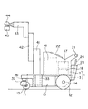
以下、この発明の実施の形態を図面に基づいて説明する。図1は、この発明に係る移動型放射線撮影装置としての移動型X線撮影装置の概要図である。 Hereinafter, embodiments of the present invention will be described with reference to the drawings. FIG. 1 is a schematic diagram of a mobile X-ray imaging apparatus as a mobile radiation imaging apparatus according to the present invention.
この移動型X線撮影装置は、ボディ2とシャーシ3とから構成される本体1を備える。この移動型X線撮影装置におけるシャーシ3の進行方向の前方側には、方向変更用の車輪である左右一対の前輪11が、回転自在な連結部材36および前輪支持部材37を介して、軸13を中心に回転可能に配設されている。また、この移動型X線撮影装置におけるシャーシ3の進行方向の後方側には、駆動用の車輪である左右一対の後輪12が、図示しないモータの駆動により、各々個別に回転する左右一対の軸14を中心に回転可能に配設されている。そして、シャーシ3における前輪11と後輪12の間の位置には、バッテリ15が配設されている。
The mobile X-ray imaging apparatus includes a main body 1 including a
本体1を構成するシャーシ3の進行方向の前方側には、支柱41が立設されており、この支柱41には、第1昇降部材42および第2昇降部材43が、昇降可能な状態で配設されている。第2昇降部材43は、側面視において略L字状の形状を有し、その先端には、X線管44とコリメータ45からなるX線照射部が配設されている。X線管44およびコリメータ45は、第1昇降部材42および第2昇降部材43の昇降動作に伴って昇降する。支柱41の下端部は円柱状の形状を有し、シャーシ3に形成された円筒形支持部材33により、鉛直軸周りに回転可能に支持されている。X線管44およびコリメータ45は、支柱41の回転に伴って、第2昇降部材43とともに旋回する。
A
本体1を構成するボディ2には、本体1の進行方向を操作するための操作ハンドル21と、表示部および操作部として機能するLCDタッチパネル22と、X線管44から照射され被検者を通過したX線を検出するためのフラットパネルディテクタ等のX線検出器24を収納するための収納部23とが配設されている。また、ボディ2の内部には、X線管44に高電圧を供給するための高電圧部16と、X線検出器24により検出したX線画像を画像処理するための画像処理部17と、後輪12を駆動するモータを制御するモータ制御部18とが配設されている。
The
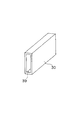
図2は、本体1を構成するシャーシ3を、バッテリ15とともに示す斜視図である。
FIG. 2 is a perspective view showing the
このシャーシ3は、前部構造体32と後部構造体31とを、上部床材35および下部床材34により連結した構造を有する。前部構造体32は、上述した連結部材36、前輪支持部材37および軸13を介して、前輪11と連結されている。前部構造体32は、上述した円筒形支持部材33を有している。また、後部構造体31には、後輪12を取り付けた減速機とモータとを取り付けるための孔部38が形成されており、これにより後部構造体31は後輪12と連結されている。
The
上部床材35および下部床材34は、前部構造体32と後部構造体31との間に、一対のバッテリ15を収納可能なスペースを形成するとともに、このスペースの左右両側方に開口部を形成した状態で、前部構造体32と後部構造体31とを連結している。これにより、上部床材35、下部床材34、前部構造体32および後部構造体31により、バッテリ15の収納スペースが形成される。そして、バッテリ15の収納スペース内には、前部構造体32と後部構造体31とを、バッテリ15の収納スペースの中央部において連結する補強部材30が配設されている。
The
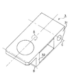
図3は、補強部材30の斜視図である。
FIG. 3 is a perspective view of the reinforcing
この補強部材30は、内部に空間39が形成された金属板よりなる中空状の形状を有する。金属板を中空状とすることにより、剛性を高めながら、その重量を小さなものとすることが可能となる。この補強部材30の先端は、前部構造体32における円筒形支持部材33に連結されている。また、この補強部材30の後端は、後部構造体31に連結されている。また、この補強部材30の上面は、上部床材35に固定されている。さらに、この補強部材30の下面は、下部床材34に固定されている。
The reinforcing
以上のような構成を有する移動型X線撮影装置において、本体1に対してバッテリ15を装着する時には、図示しないコネクタ等により本体1側と一対のバッテリ15側とを電気的に接続した上で、各バッテリ15を、シャーシ3におけるバッテリ15の収納スペースの左右両側方に形成された開口部から収納スペース内に収納する。これにより、大型で重量の大きなバッテリ15を、移動型X線撮影装置の本体1の下方のシャーシ3の内部に収納することが可能となる。このため、重量の大きなバッテリ15を本体1の下方に配置することができることから、移動型X線撮影装置を安定して走行させることが可能となる。
In the mobile X-ray imaging apparatus having the above-described configuration, when the
このとき、一対のバッテリ15を、バッテリ15の収納スペースの左右両側方に形成された開口部を介して収納スペース内に収納する構成であることから、本体1におけるボディ2内に、高電圧部16、画像処理部17、モータ制御部18等が配設されていた場合においても、これらの部材を取り外すことなく、バッテリ15を装着し、あるいは、交換することが可能となる。
At this time, since the pair of
図4は、シャーシ3におけるねじれの発生状態を示す説明図である。
FIG. 4 is an explanatory diagram showing a state of occurrence of twisting in the
上述した移動型X線撮影装置を走行させた場合においては、一対の前輪11および一対の後輪12は、床面の凹凸等により床面からの衝撃を受け、シャーシ3に対してねじれ方向の力が付与される。これにより、シャーシ3に対しては、図4において矢印Aで示すように、前輪11からの入力点(前輪11への力がシャーシ3に働く点)を繋ぐ線Bと後輪12からの入力点(後輪12への力がシャーシ3に働く点)を繋ぐ線Cとに対して直交する方向を向く軸を中心にねじれを生じる力が付与される。しかしながら、この発明に係る移動型X線撮影装置においては、前部構造体32と後部構造体31とを連結する補強部材30の作用により、シャーシ3に対するねじれの発生が抑制される。このため、支柱41の揺れが抑制され、第1、第2昇降部材42、43や、X線管44およびコリメータ45が大きく揺れることを防止し、移動型X線撮影装置を安定して走行させることが可能となる。
When the above-described mobile X-ray imaging apparatus is run, the pair of
特に、上述した移動型X線撮影装置においては、補強部材30の上面が上部床材35に固定され、補強部材30の下面が下部床材34に固定されていることから、これらの上部床材35、下部床材34および補強部材30により、断面が略H字状の構造体が構成され、シャーシ3に生ずるねじれを有効に防止することが可能となる。
In particular, in the mobile X-ray imaging apparatus described above, the upper surface of the reinforcing
さらに、上述した移動型X線撮影装置においては、補強部材30の先端が、前部構造体32における円筒形支持部材33に連結されている。この円筒形支持部材33は、通常、直径が30センチメートル以上の金属製円筒部材から構成されており、図4に示す矢印A方向のねじれに対して極めて強い構造体となっている。これにより、シャーシ3に生ずるねじれをさらに有効に防止することが可能となる。
Further, in the above-described mobile X-ray imaging apparatus, the distal end of the reinforcing
なお、上述した実施形態においては、補強部材30をバッテリ15の収納スペースの中央部に配置しているが、補強部材30の位置は、バッテリ15を収納可能なスペースの中央領域であれば、中央部から左右方向にある程度移動させてもよい。例えば、上述した実施形態においては、バッテリ15の収納スペースの両側に形成された開口部から、同一サイズの一対のバッテリ15を収納している。しかしながら、一対のバッテリ15のサイズが異なる場合には、補強部材30の配置を中央部から左右方向に移動させてもよい。また、例えば、右側方から2個のバッテリを収納し、左側方から3個のバッテリを収納する場合等においても、補強部材30の位置を、バッテリを収納可能なスペースの中央部から左右方向に移動させてもよい。補強部材30は、バッテリを収納可能なスペースの中央領域に配置されていればよい。またバッテリ15は1個のバッテリではなく複数のバッテリの集合体でも良い。
In the above-described embodiment, the reinforcing
また、上述した実施形態においては、補強部材30を上部床材35と下部床材34の両方に固定しているが、これらのうちのいずれか一方と固定するようにしてもよい。また、十分な強度を得られる場合には、補強部材30を上部床材35および下部床材34に対して固定しない構成を採用してもよい。
Moreover, in the embodiment mentioned above, although the
また、上述した実施形態においては、第1昇降部材42および第2昇降部材43により、X線管44およびコリメータ45よりなるX線照射部を昇降させているが、第1昇降部材42と第2昇降部材43を使用するかわりに、単一の昇降部材、あるいは、3個以上の昇降部材を使用し、この昇降部材によりX線照射部を昇降させてもよい。
In the above-described embodiment, the X-ray irradiation unit including the
また、上述した実施形態においては、側面視において略L字状の形状を有する第2昇降部材43によりX線管44およびコリメータ45からなるX線照射部を支持しているが、X線照射部を支持する支持部材としては、その他の任意の形状のものを使用することが可能である。
In the above-described embodiment, the X-ray irradiation unit including the
1 本体
2 ボディ
3 シャーシ
11 前輪
12 後輪
13 軸
14 軸
15 バッテリ
30 補強部材
31 後部構造体
32 前部構造体
33 円筒形支持部材
34 下部床材
35 上部床材
36 連結部材
37 前輪支持部材
39 空間
41 支柱
42 第1昇降部材
43 第2昇降部材
44 X線管
45 コリメータDESCRIPTION OF SYMBOLS 1
Claims (4)
前記本体を構成するシャーシは、
前記前輪と連結される前部構造体と、
前記後輪と連結される後部構造体と、
前記前部構造体と前記後部構造体との間に前記バッテリを収納可能なスペースを形成するとともに、当該スペースの左右両側方に開口部を形成した状態で、前記前部構造体と前記後部構造体とを連結する床材と、
前記前部構造体と前記後部構造体とを、前記バッテリを収納可能なスペースの中央領域において連結する補強部材と、
を備え、
複数のバッテリを、前記バッテリを収納可能なスペースの左右両側方に形成された開口部から、当該スペース内に収納することを特徴とする移動型放射線撮影装置。A main body having a front wheel and a rear wheel; a support column erected on the main body; a lifting member that moves up and down along the support column while supporting a radiation irradiation unit; and a battery disposed inside the main body. In the mobile radiography apparatus provided,
The chassis constituting the main body is:
A front structure coupled to the front wheel;
A rear structure coupled to the rear wheel;
A space in which the battery can be stored is formed between the front structure and the rear structure, and the front structure and the rear structure are formed with openings on the left and right sides of the space. Flooring connecting the body,
A reinforcing member that connects the front structure and the rear structure in a central region of a space in which the battery can be stored;
With
A mobile radiographic apparatus characterized in that a plurality of batteries are accommodated in the space from openings formed on both left and right sides of the space in which the battery can be accommodated.
前記前部構造体と前記後部構造体とは、前記バッテリの上部に配置される上部床材と、前記バッテリの下部に配置される下部床材とにより連結されており、
前記補強部材は、前記上部床材または前記下部床材の少なくとも一方に固定されている移動型放射線撮影装置。The mobile radiation imaging apparatus according to claim 1,
The front structure and the rear structure are connected to each other by an upper flooring disposed at the top of the battery and a lower flooring disposed at the bottom of the battery,
The reinforcing member is a mobile radiography apparatus fixed to at least one of the upper floor material or the lower floor material.
前記補強部材は、中空状の形状を有する移動型放射線撮影装置。The mobile radiation imaging apparatus according to claim 2,
The reinforcing member is a mobile radiographic apparatus having a hollow shape.
前記前部構造体は、前記支柱を鉛直軸周りに回転可能に支持するための円筒形支持部材を備え、
前記補強部材は、前記円筒形支持部材に連結されている移動型放射線撮影装置。
In the mobile radiography apparatus according to any one of claims 1 to 3,
The front structure includes a cylindrical support member for rotatably supporting the support column around a vertical axis,
The mobile radiography apparatus, wherein the reinforcing member is connected to the cylindrical support member.
Applications Claiming Priority (1)
| Application Number | Priority Date | Filing Date | Title |
|---|---|---|---|
| PCT/JP2017/003895 WO2018142557A1 (en) | 2017-02-03 | 2017-02-03 | Portable radiation imaging apparatus |
Publications (2)
| Publication Number | Publication Date |
|---|---|
| JPWO2018142557A1 JPWO2018142557A1 (en) | 2019-06-27 |
| JP6617841B2 true JP6617841B2 (en) | 2019-12-11 |
Family
ID=63039407
Family Applications (1)
| Application Number | Title | Priority Date | Filing Date |
|---|---|---|---|
| JP2018565182A Active JP6617841B2 (en) | 2017-02-03 | 2017-02-03 | Mobile radiography system |
Country Status (4)
| Country | Link |
|---|---|
| US (1) | US10772588B2 (en) |
| JP (1) | JP6617841B2 (en) |
| CN (1) | CN110035698B (en) |
| WO (1) | WO2018142557A1 (en) |
Families Citing this family (4)
| Publication number | Priority date | Publication date | Assignee | Title |
|---|---|---|---|---|
| US10772588B2 (en) * | 2017-02-03 | 2020-09-15 | Shimadzu Corporation | Portable radiation imaging apparatus |
| CN110251149A (en) * | 2019-07-31 | 2019-09-20 | 曹顺山 | A kind of mobile X-ray unit |
| CN112494059B (en) * | 2020-12-01 | 2022-01-28 | 深圳市宝润科技有限公司 | Mobile X-ray machine |
| US12458308B2 (en) | 2022-12-07 | 2025-11-04 | GE Precision Healthcare LLC | Mobile x-ray device with telescopic column including counterbalancing compression spring mechanism |
Family Cites Families (20)
| Publication number | Priority date | Publication date | Assignee | Title |
|---|---|---|---|---|
| JP2000041976A (en) * | 1998-07-31 | 2000-02-15 | Shimadzu Corp | Mobile X-ray equipment |
| CN2480820Y (en) * | 2001-06-29 | 2002-03-06 | 刘毅 | Photoelectric cell X-ray sensor |
| JP2005006888A (en) * | 2003-06-19 | 2005-01-13 | Canon Inc | Radiation imaging equipment |
| US20050135560A1 (en) * | 2003-12-17 | 2005-06-23 | Ehud Dafni | Portable computed tomography scanner and methods thereof |
| JP2007289408A (en) | 2006-04-25 | 2007-11-08 | Shimadzu Corp | X-ray imaging apparatus for round trip, receiving antenna position detection apparatus, and wireless power supply apparatus thereof |
| CN102065768A (en) * | 2008-07-10 | 2011-05-18 | 株式会社日立医疗器械 | Mobile X-ray apparatus |
| JP4829949B2 (en) * | 2008-10-22 | 2011-12-07 | 東芝Itコントロールシステム株式会社 | Battery inspection device |
| JP5442307B2 (en) * | 2009-04-22 | 2014-03-12 | 株式会社日立メディコ | Mobile X-ray device |
| CN102232839A (en) * | 2010-04-30 | 2011-11-09 | 富士胶片株式会社 | Movable radiation image detection device |
| WO2012032688A1 (en) * | 2010-09-10 | 2012-03-15 | 株式会社島津製作所 | Mobile radiography device |
| US8459868B2 (en) * | 2010-11-23 | 2013-06-11 | General Electric Company | Portable X-ray machine with drive wheel suspension |
| JP5827857B2 (en) * | 2011-09-28 | 2015-12-02 | 富士フイルム株式会社 | Radiation image detection device |
| US9198270B2 (en) * | 2011-11-18 | 2015-11-24 | Virtual Imaging, Inc. | Radiographic imaging apparatus with distributed antenna system |
| JP2014073309A (en) * | 2012-10-05 | 2014-04-24 | Canon Inc | Mobile radiation generation apparatus and mobile radiation imaging system |
| JP6142534B2 (en) * | 2013-01-08 | 2017-06-07 | 株式会社島津製作所 | X-ray equipment |
| US10058303B2 (en) * | 2014-04-03 | 2018-08-28 | Hitachi, Ltd. | Mobile X-ray imaging apparatus |
| JP2015208573A (en) * | 2014-04-28 | 2015-11-24 | キヤノン株式会社 | Radiation generator |
| JP6488455B2 (en) * | 2014-08-28 | 2019-03-27 | トーレック株式会社 | Power supply system and medical X-ray system |
| JP6145899B2 (en) * | 2015-07-16 | 2017-06-14 | 富士フイルム株式会社 | Radiation imaging equipment |
| US10772588B2 (en) * | 2017-02-03 | 2020-09-15 | Shimadzu Corporation | Portable radiation imaging apparatus |
-
2017
- 2017-02-03 US US16/476,303 patent/US10772588B2/en active Active
- 2017-02-03 WO PCT/JP2017/003895 patent/WO2018142557A1/en not_active Ceased
- 2017-02-03 JP JP2018565182A patent/JP6617841B2/en active Active
- 2017-02-03 CN CN201780071604.7A patent/CN110035698B/en active Active
Also Published As
| Publication number | Publication date |
|---|---|
| CN110035698B (en) | 2023-04-04 |
| US20190350544A1 (en) | 2019-11-21 |
| JPWO2018142557A1 (en) | 2019-06-27 |
| CN110035698A (en) | 2019-07-19 |
| WO2018142557A1 (en) | 2018-08-09 |
| US10772588B2 (en) | 2020-09-15 |
Similar Documents
| Publication | Publication Date | Title |
|---|---|---|
| JP6617841B2 (en) | Mobile radiography system | |
| JP2014533188A5 (en) | ||
| JP5911213B2 (en) | X-ray CT system | |
| JP6438333B2 (en) | Mobile X-ray equipment | |
| US10993682B2 (en) | Radiographic imaging apparatus comprising a leg unit having three or more wheel units | |
| JP4902581B2 (en) | Control console with multiple usage positions | |
| CN103732144B (en) | The control method of the mobile X-ray diagnostic equipment and the mobile X-ray diagnostic equipment | |
| US10980500B2 (en) | Mobile radiographic imaging apparatus | |
| US20180110490A1 (en) | Mobile x-ray imaging apparatus | |
| JP4797899B2 (en) | Mobile X-ray equipment | |
| US20140098938A1 (en) | Mobile x-ray imaging apparatus | |
| US10674977B2 (en) | Radiographic imaging apparatus | |
| JP2019037476A (en) | Movable type radiographic apparatus | |
| CN108778133B (en) | Mobile radiation system | |
| WO2014088042A1 (en) | X-ray computed tomographic device | |
| CN114776983B (en) | A mobile device for ray detector | |
| JP2009012510A (en) | Carriage | |
| JP2005162113A (en) | Caster and mobile medical image diagnostic device | |
| WO2021085245A1 (en) | Mobile radiography device | |
| WO2013145822A1 (en) | Mobile x-ray device and method for taking out flat plate detector | |
| JP5414408B2 (en) | Mobile X-ray device | |
| JPH0471538A (en) | Mobile x-ray device | |
| IT202300003399A1 (en) | REMOTE CONTROL TABLE FOR THE TREATMENT OF RADIOLOGICAL EXAMINATIONS | |
| JP2008061780A (en) | X-ray equipment | |
| JP2017035167A (en) | Mobile x-ray apparatus |
Legal Events
| Date | Code | Title | Description |
|---|---|---|---|
| A621 | Written request for application examination |
Free format text: JAPANESE INTERMEDIATE CODE: A621 Effective date: 20190226 |
|
| TRDD | Decision of grant or rejection written | ||
| A01 | Written decision to grant a patent or to grant a registration (utility model) |
Free format text: JAPANESE INTERMEDIATE CODE: A01 Effective date: 20191015 |
|
| A61 | First payment of annual fees (during grant procedure) |
Free format text: JAPANESE INTERMEDIATE CODE: A61 Effective date: 20191028 |
|
| R151 | Written notification of patent or utility model registration |
Ref document number: 6617841 Country of ref document: JP Free format text: JAPANESE INTERMEDIATE CODE: R151 |