WO2021085245A1 - Mobile radiography device - Google Patents
Mobile radiography device Download PDFInfo
- Publication number
- WO2021085245A1 WO2021085245A1 PCT/JP2020/039423 JP2020039423W WO2021085245A1 WO 2021085245 A1 WO2021085245 A1 WO 2021085245A1 JP 2020039423 W JP2020039423 W JP 2020039423W WO 2021085245 A1 WO2021085245 A1 WO 2021085245A1
- Authority
- WO
- WIPO (PCT)
- Prior art keywords
- steering
- caster
- mobile radiography
- casters
- free
- Prior art date
Links
Images


Classifications
-
- A—HUMAN NECESSITIES
- A61—MEDICAL OR VETERINARY SCIENCE; HYGIENE
- A61B—DIAGNOSIS; SURGERY; IDENTIFICATION
- A61B6/00—Apparatus for radiation diagnosis, e.g. combined with radiation therapy equipment
- A61B6/44—Constructional features of apparatus for radiation diagnosis
- A61B6/4429—Constructional features of apparatus for radiation diagnosis related to the mounting of source units and detector units
- A61B6/4435—Constructional features of apparatus for radiation diagnosis related to the mounting of source units and detector units the source unit and the detector unit being coupled by a rigid structure
- A61B6/4441—Constructional features of apparatus for radiation diagnosis related to the mounting of source units and detector units the source unit and the detector unit being coupled by a rigid structure the rigid structure being a C-arm or U-arm
-
- A—HUMAN NECESSITIES
- A61—MEDICAL OR VETERINARY SCIENCE; HYGIENE
- A61B—DIAGNOSIS; SURGERY; IDENTIFICATION
- A61B6/00—Apparatus for radiation diagnosis, e.g. combined with radiation therapy equipment
- A61B6/44—Constructional features of apparatus for radiation diagnosis
- A61B6/4405—Constructional features of apparatus for radiation diagnosis the apparatus being movable or portable, e.g. handheld or mounted on a trolley
-
- A—HUMAN NECESSITIES
- A61—MEDICAL OR VETERINARY SCIENCE; HYGIENE
- A61B—DIAGNOSIS; SURGERY; IDENTIFICATION
- A61B6/00—Apparatus for radiation diagnosis, e.g. combined with radiation therapy equipment
- A61B6/10—Application or adaptation of safety means
-
- A—HUMAN NECESSITIES
- A61—MEDICAL OR VETERINARY SCIENCE; HYGIENE
- A61B—DIAGNOSIS; SURGERY; IDENTIFICATION
- A61B6/00—Apparatus for radiation diagnosis, e.g. combined with radiation therapy equipment
- A61B6/10—Application or adaptation of safety means
- A61B6/102—Protection against mechanical damage, e.g. anti-collision devices
- A61B6/105—Braking or locking devices
-
- A—HUMAN NECESSITIES
- A61—MEDICAL OR VETERINARY SCIENCE; HYGIENE
- A61B—DIAGNOSIS; SURGERY; IDENTIFICATION
- A61B6/00—Apparatus for radiation diagnosis, e.g. combined with radiation therapy equipment
- A61B6/44—Constructional features of apparatus for radiation diagnosis
- A61B6/4476—Constructional features of apparatus for radiation diagnosis related to motor-assisted motion of the source unit
- A61B6/4482—Constructional features of apparatus for radiation diagnosis related to motor-assisted motion of the source unit involving power assist circuits
-
- A—HUMAN NECESSITIES
- A61—MEDICAL OR VETERINARY SCIENCE; HYGIENE
- A61B—DIAGNOSIS; SURGERY; IDENTIFICATION
- A61B6/00—Apparatus for radiation diagnosis, e.g. combined with radiation therapy equipment
- A61B6/54—Control of apparatus or devices for radiation diagnosis
-
- A—HUMAN NECESSITIES
- A61—MEDICAL OR VETERINARY SCIENCE; HYGIENE
- A61B—DIAGNOSIS; SURGERY; IDENTIFICATION
- A61B6/00—Apparatus for radiation diagnosis, e.g. combined with radiation therapy equipment
- A61B6/58—Testing, adjusting or calibrating apparatus or devices for radiation diagnosis
- A61B6/586—Detection of faults or malfunction of the device
-
- B—PERFORMING OPERATIONS; TRANSPORTING
- B60—VEHICLES IN GENERAL
- B60B—VEHICLE WHEELS; CASTORS; AXLES FOR WHEELS OR CASTORS; INCREASING WHEEL ADHESION
- B60B33/00—Castors in general; Anti-clogging castors
- B60B33/04—Castors in general; Anti-clogging castors adjustable, e.g. in height; linearly shifting castors
- B60B33/06—Castors in general; Anti-clogging castors adjustable, e.g. in height; linearly shifting castors mounted retractably
- B60B33/063—Castors in general; Anti-clogging castors adjustable, e.g. in height; linearly shifting castors mounted retractably by linear movement parallel to swivel axis
-
- B—PERFORMING OPERATIONS; TRANSPORTING
- B62—LAND VEHICLES FOR TRAVELLING OTHERWISE THAN ON RAILS
- B62B—HAND-PROPELLED VEHICLES, e.g. HAND CARTS OR PERAMBULATORS; SLEDGES
- B62B3/00—Hand carts having more than one axis carrying transport wheels; Steering devices therefor; Equipment therefor
- B62B3/001—Steering devices
-
- B—PERFORMING OPERATIONS; TRANSPORTING
- B62—LAND VEHICLES FOR TRAVELLING OTHERWISE THAN ON RAILS
- B62B—HAND-PROPELLED VEHICLES, e.g. HAND CARTS OR PERAMBULATORS; SLEDGES
- B62B3/00—Hand carts having more than one axis carrying transport wheels; Steering devices therefor; Equipment therefor
- B62B3/008—Hand carts having more than one axis carrying transport wheels; Steering devices therefor; Equipment therefor having more than two axes
-
- B—PERFORMING OPERATIONS; TRANSPORTING
- B62—LAND VEHICLES FOR TRAVELLING OTHERWISE THAN ON RAILS
- B62B—HAND-PROPELLED VEHICLES, e.g. HAND CARTS OR PERAMBULATORS; SLEDGES
- B62B2301/00—Wheel arrangements; Steering; Stability; Wheel suspension
- B62B2301/04—Wheel arrangements; Steering; Stability; Wheel suspension comprising a wheel pivotable about a substantially vertical axis, e.g. swivelling castors
- B62B2301/044—Wheel arrangements; Steering; Stability; Wheel suspension comprising a wheel pivotable about a substantially vertical axis, e.g. swivelling castors arranged remote from the longitudinal centreline of the hand propelled vehicle
Definitions
- This disclosure relates to a mobile radiography apparatus.
- a mobile radiography apparatus having an irradiation unit for irradiating radiation and a traveling carriage portion is known (see JP-A-2011-87923).
- the dolly portion is provided with a plurality of casters, and a support portion and a main body portion that support an arm provided with an irradiation portion are mounted.
- the steering caster is a caster to which the steering is combined, and the steering angle is given by the operation of the steering. This makes it possible to fix the traveling direction of the bogie portion by operating the steering wheel.
- the free caster is not connected to the steering wheel, and the steering angle changes subordinately according to the force applied to the bogie.
- Such a mobile radiography device may be used in a hospital room or an operating room in addition to being used in a radiography room.
- the mobile radiography apparatus When photographing a patient who is difficult to move to the imaging room, the mobile radiography apparatus is carried into the patient's room and used in the patient's room.
- a moving image of a treatment target site of a patient undergoing surgery is taken, it is carried into the operating room and used in the operating room.
- the operability required for the trolley portion changes according to each usage scene.
- the hospital room is smaller than the imaging room, it is required to have a smaller turn than the imaging room.
- the orientation of the trolley can be easily changed by pushing and pulling the mobile radiography device from various directions without having to bother to operate the steering wheel. There is a request to let me do it.
- imaging may be performed while sequentially moving the imaging position along the body axis of the patient. In such a case, if the bogie portion fluctuates, it is not possible to take an appropriate picture. Therefore, there is a demand to fix the traveling direction of the bogie portion by fixing the steering position.
- the technology according to the present disclosure provides a mobile radiography apparatus capable of changing the operability of the trolley portion according to the usage situation.
- the mobile radiography apparatus is provided with an irradiation unit for irradiating radiation, a carriage unit on which the irradiation unit is mounted and capable of traveling, a carriage portion, and is connected to a steering wheel.
- Steering casters whose steering angle is given by steering operation, and free casters which are provided on the bogie and are not connected to the steering wheel and whose steering angle changes subordinately according to the direction of the force applied to the bogie.
- the operability of the bogie can be changed according to the usage situation by selectively switching the ground contact state of the free caster and the steering caster by the switching mechanism.
- the bogie can be turned in a small turn, while by grounding the steering casters, the traveling direction of the bogie can be fixed. If it is easy to turn around, it is easy to use when using it in a small hospital room. If the direction of travel can be fixed, it is convenient when continuous shooting is performed while moving the shooting position.
- the mobile radiography apparatus is the mobile radiography apparatus according to the first aspect, in which the switching mechanism raises and lowers the free caster with respect to the steering caster to bring the free caster up and down to the first ground contact state. 2 Switch between the grounded state.
- the steering caster is heavier than the free caster because it is connected to the steering wheel.
- the ground contact state of the caster can be easily switched with a light force as compared with the configuration in which the steering caster side is raised and lowered.
- the mobile radiography apparatus is the mobile radiography apparatus according to the second aspect, and the switching mechanism has a pedal for raising and lowering the free caster.
- the free caster can be raised and lowered by stepping on the pedal with the foot, it is possible to switch the ground contact state of the caster while manually operating the mobile radiography apparatus.
- the mobile radiography apparatus is the mobile radiography apparatus according to any one of the first to third aspects, in which the first ground contact state is provided in addition to the free casters and the steering casters. In both the second grounding state and the second grounding state, a constant grounding caster is provided to ground the floor.
- the always-grounded casters are provided, so that the bogie portion can be stably driven even when one of the free casters and the steering casters is separated from the floor. be able to.
- the bogie portion can be stably driven even when one of the free casters and the steering casters is separated from the floor. be able to.
- the mobile radiography apparatus is the main body of the mobile radiography apparatus according to the fourth aspect, wherein the carriage portion has an arm for supporting the irradiation portion and a control unit for controlling the irradiation portion.
- the always-grounded caster is a caster whose steering angle changes subordinately like a free caster, and the side where the arm is provided is in front of the bogie and the main body is provided. When the side facing is the rear of the bogie, the casters are always in contact with the ground, the steering casters, and the free casters from the front to the rear of the bogie.
- the steering casters can be arranged at a position close to the position of the center of gravity of the main body portion. As a result, it is possible to prevent the posture of the main body from becoming unstable when the steering is operated.
- the mobile radiography apparatus is the mobile radiography apparatus according to the fifth aspect, in which the steering casters are arranged at the center of gravity in the front-rear direction of the carriage portion.
- the mobile radiography apparatus is the mobile radiography apparatus according to the fifth or sixth aspect, wherein the arm has two ends, and one end of the arm has two ends.
- An irradiation unit is provided, and an image receiving unit that receives radiation emitted from the irradiation unit and transmitted through the subject is provided at the other end of the arm.
- the mobile radiography apparatus is the mobile radiography apparatus according to any one of the first to seventh aspects, in a second ground contact state in which the steering caster is separated from the floor. It has a steering lock mechanism that locks the operation by steering.
- the above configuration has a steering lock mechanism that locks the operation by steering when the steering caster is separated from the floor.
- a steering lock mechanism that locks the operation by steering when the steering caster is separated from the floor.
- the handle for pushing and pulling the carriage portion is a steering wheel. Is provided separately.
- FIG. 2 is a side view showing a state in which the arm of the mobile radiography apparatus shown in FIG. 2A is rotated in the direction of arrow M1.
- FIG. 2 is a side view showing a state in which the arm of the mobile radiography apparatus shown in FIG. 2A is rotated in the direction of arrow M2.
- FIG. 3 is a front view showing a state in which the arm of the mobile radiography apparatus shown in FIG. 3A is rotated in the direction of arrow N1.
- FIG. 3 is a front view showing a state in which the arm of the mobile radiography apparatus shown in FIG. 3A is rotated by 180 ° in the direction of arrow N2. It is an overall side view which shows the 1st grounding state of the mobile radiography apparatus which concerns on an example of Embodiment. It is an overall side view which shows the 2nd grounding state of the mobile radiography apparatus which concerns on an example of Embodiment. It is a top view which shows the mobile radiography apparatus which concerns on an example of Embodiment.
- FIG. 3 is a plan view showing a state in which the steering of the mobile radiography apparatus shown in FIG. 6 is operated in one direction.
- FIG. 5 is a plan view showing a state in which the steering of the mobile radiography apparatus shown in FIG.
- FIG. 6 is operated in another direction. It is a perspective view which shows the switching mechanism of the mobile radiography apparatus which concerns on an example of Embodiment. It is an exploded perspective view of the switching mechanism shown in FIG. It is a side view which shows the switching mechanism in the 1st grounding state. It is a side view which shows the switching mechanism in the 2nd grounding state. It is a perspective view which shows the unlocked state of the steering by the steering lock mechanism. It is a perspective view which shows the locked state of the steering by the steering lock mechanism.
- the mobile radiography apparatus according to an example of the embodiment of the present disclosure will be described with reference to the drawings.
- the arrow X indicates the front-back direction of the mobile radiography apparatus
- the arrow Y indicates the width direction of the mobile radiography apparatus
- the arrow Z indicates the vertical direction.
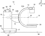
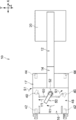
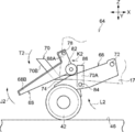
- the mobile radiography apparatus 10 of the present embodiment shown in FIG. 1 is an apparatus for photographing a radiographic image of a subject H.
- the mobile radiation photographing apparatus 10 can, for example, take a moving image and a still image of the subject H.
- the moving image shooting is performed, for example, when displaying the treatment target site of the subject H as a moving image (also referred to as fluoroscopic photography or the like) during surgery.
- a moving image of the subject H is displayed on a monitor (not shown) installed separately from the mobile radiation photographing device 10.
- a monitor not shown
- still image shooting it is possible to display the shot still image on the monitor and save it in the memory in the mobile radiography apparatus 10.
- the mobile radiography apparatus 10 includes an arm 12 (called a C arm or the like) having a C-shaped (arc-shaped) side surface, and a main body 16 to which a support portion 14 is attached. have.
- the arm 12, the support portion 14, and the main body portion 16 are mounted on the carriage portion 17.
- the side of the mobile radiography apparatus 10 where the arm 12 is provided is the front of the mobile radiography apparatus 10
- the side where the main body 16 is provided is the rear of the mobile radiography apparatus 10. ..
- the arm 12 has two end portions, an irradiation portion 18 is provided at one end of the arm 12, and an image receiving portion 20 is provided at the other end.
- the arm 12 can hold the irradiation unit 18 and the image receiving unit 20 in a facing posture.
- a space is secured between the irradiation unit 18 and the image receiving unit 20 so that the subject H and the sleeper S on which the subject H is lying can be inserted.
- the direction in which the irradiation unit 18 and the image receiving unit 20 are provided is the front of the arm 12, and the support 14 side is the rear of the arm 12. May be called.
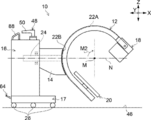
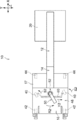
- the arm 12 can orbitally rotate about the axis M (the axis parallel to the Y axis) with respect to the orbital portion 22B provided on the support portion 14. Further, the arm 12 is rotatable about an axis N (an axis parallel to the X axis) with respect to the bearing portion 23 provided on the main body portion 16.
- the track portion 22B has an arc shape having the same radius as the arc of the arm 12.
- a fitting portion 22A that fits into the track portion 22B is provided on the outer peripheral portion of the arm 12.
- the fitting portion 22A has an arc shape that follows the shape of the arm 12.
- the track portion 22B has, for example, a groove shape, and a convex fitting portion 22A is fitted.
- the fitting portion 22A formed on the arm 12 slides along the track portion 22B formed on the support portion 14.
- the arm 12 can orbitally rotate with respect to the support portion 14 and the main body portion 16 with the axis M at the center of the arc of the arm 12 as the center of rotation.
- the arm 12 can be orbitally rotated around the axis M in the direction of arrow M1 (counterclockwise in FIG. 2B) and in the direction of arrow M2 (clockwise in FIG. 2C), respectively.
- the irradiation unit 18 and the image receiving unit 20 provided at both ends of the arm 12 can be rotated around the body axis (axis parallel to the Y axis) of the subject H (see FIG. 1) in a posture of facing each other.
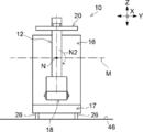
- one end of a support shaft 24 extending in the front-rear direction (X direction) of the mobile radiography apparatus 10 is fixed to the arm 12.
- the other end of the support shaft 24 is supported by the main body portion 16 via a bearing portion 23.
- the support shaft 24 rotates about the axis N with respect to the bearing portion 23, as shown in FIGS. 3A to 3C, the arm 12 and the support portion 14 have the main body portion with the axis N of the support shaft 24 as the center of rotation. It is said that the axis can be rotated with respect to 16.
- this posture is called an overtube posture or the like.
- the radiation tube 32 is located below the subject H. For this reason, this posture is called the undertube posture.
- the overtube posture can have a wider distance between the irradiation unit 18 and the subject H (see FIG. 1) than the undertube posture. This makes it possible to capture a relatively wide area in the overtube posture. Therefore, the overtube posture is mainly used when taking a still image of the subject H.
- the undertube posture the radiation emitted from the irradiation unit 18 is partially shielded by the sleeper S or the like. As a result, in the undertube posture, the exposure dose of the operator, the operator, or the like (not shown) around the subject H (see FIG. 1) can be reduced. Therefore, the undertube posture is used when shooting a moving image of the subject H in which continuous irradiation of radiation is performed.
- the main body 16 of the mobile radiography apparatus 10 includes a control unit 28 that controls each part of the mobile radiography apparatus 10 such as the irradiation unit 18, and a touch panel type operation panel 30, for example. Have.
- the main body 16 includes various switches (not shown) such as a power switch of the mobile radiography apparatus 10, a power supply circuit for supplying electric power to each part of the mobile radiography apparatus 10, a battery, and the like.
- the operation panel 30 functions as an operation unit for operating each part by inputting an operation instruction to each part of the mobile radiography apparatus 10, and also has various types such as a warning message and a radiation image output from the image receiving unit 20. It functions as a display unit that displays information.
- the control unit 28 controls the tube voltage, tube current, radiation irradiation time, and the like of the radiation tube 32 by transmitting a control signal to the radiation tube 32 of the irradiation unit 18, which will be described later.
- the energy of radiation is controlled by the control unit 28 controlling the tube voltage.
- the radiation dose is controlled by the control unit 28 controlling the tube current and the irradiation time.
- the control unit 28 controls the radiation tube 32 through a high voltage generator (not shown).
- the photographing conditions including the tube voltage, the tube current, the irradiation time and the like are set through the operation panel 30.
- the control unit 28 operates the irradiation unit 18 based on the set imaging conditions.
- the control unit 28 enables the irradiation unit 18 to shoot a moving image of the subject H by causing the irradiation unit 18 to continuously irradiate the irradiation unit 18 with radiation for moving image shooting.
- the control unit 28 operates the detector of the image receiving unit 20 described later in synchronization with the irradiation for moving image shooting of the irradiation unit 18.
- the irradiation time is basically not set as a shooting condition, and instructions for starting and ending movie shooting are given through the operation panel 30.
- the control unit 28 starts irradiation of radiation from the irradiation unit 18 under preset shooting conditions.
- the detector repeats the image detection operation at a preset frame rate while the movie shooting irradiation is being performed.
- the image output by the detector is transmitted to the control unit 28.
- the control unit 28 sequentially outputs the received images to a monitor (not shown). As a result, the moving image of the subject H is displayed on the monitor.
- control unit 28 makes it possible to shoot a still image of the subject H by causing the irradiation unit 18 to irradiate the irradiation unit 18 with radiation for a shorter period of time than the irradiation for moving image shooting. To do.
- the control unit 28 operates the detector of the image receiving unit 20 in synchronization with the irradiation timing of the still image irradiation of the irradiation unit 18.
- the instruction for still image shooting is given, for example, through an irradiation switch (not shown) connected to the control unit 28.
- the irradiation time is, for example, on the order of several tens of milliseconds to several hundreds of milliseconds.
- the control unit 28 operates the irradiation unit 18 based on preset shooting conditions. In the case of still image shooting, since the irradiation time is set in the shooting conditions, the irradiation of the irradiation unit 18 ends when the set irradiation time elapses.
- the detector starts outputting the detected image when the irradiation is completed.
- the image output by the detector is transmitted to the control unit 28.
- the control unit 28 stores still image data in a memory (not shown).
- the saved still image is displayed on a monitor (not shown).
- the still image of the subject H is displayed on the monitor.
- the still image may be displayed on the operation panel 30 in order to confirm the still image taken immediately after the shooting.
- the irradiation unit 18 includes a radiation source 31 and an irradiation field limiting device 34.
- the radiation source 31 includes a radiation tube 32 that generates radiation. Radiation is, for example, X-rays.
- the radiation tube 32 generates radiation by colliding electrons generated from the cathode with a target (anode). The position where the electrons collide with the target is the focal point where the radiation is emitted.
- an irradiation field limiting device 34 is provided below the radiation source 31.
- the irradiation field limiter 34 (also referred to as a collimator or the like) has a rectangular irradiation opening 34A.
- the radiation generated in the radiation tube 32 is applied to the subject H through the irradiation opening 34A.
- the irradiation field limiter 34 can adjust the opening area of the irradiation opening 34A.
- the irradiation field limiter 34 has, for example, four shielding plates (not shown) that shield the radiation. Each side of each of the four shielding plates corresponds to each side of the irradiation opening 34A, and defines the irradiation opening 34A. By changing the position of the shielding plate, the opening area of the irradiation opening 34A is adjusted, and the irradiation field of the radiation emitted from the irradiation unit 18 is changed.
- the irradiation unit 18 is rotatable with respect to the arm 12 with the axis of the rotation shaft 36 extending in the width direction (Y direction in FIG. 1) of the mobile radiography apparatus 10 as the center of rotation. Specifically, a pair of mounting plates 38 (only one is shown in FIG. 1) are fixed to one end of the arm 12.
- the pair of mounting plates 38 are arranged so as to sandwich both sides of the irradiation unit 18 in the width direction, and are connected to both side surfaces of the irradiation unit 18 in the width direction.
- a rotating shaft 36 is projected from each side surface of the irradiation unit 18 facing each mounting plate 38, and the rotating shaft 36 is supported by a pair of mounting plates 38 via bearings (not shown).
- the irradiation unit 18 can rotate with respect to the mounting plate 38 with the axis of the rotation shaft 36 as the center of rotation, and the direction of the irradiation opening 34A of the irradiation unit 18 can be changed in the front-rear direction of the arm 12. ..
- the direction of the irradiation opening 34A By changing the direction of the irradiation opening 34A, the irradiation direction of radiation can be changed.
- the irradiation unit 18 is connected to the control unit 28 of the main body 16 and a power supply circuit (not shown) by a cable (not shown) in which a signal line for transmitting a control signal and a power supply line for power supply are wired. There is.
- the image receiving unit 20 is provided at the other end of the arm 12, which is a position facing the irradiation unit 18.
- the image receiving portion 20 is non-detachably fixed to the other end of the arm 12, but the image receiving portion 20 may be detachably attached to the other end of the arm 12. ..
- the image receiving unit 20 is provided with a detector inside the housing.
- the image receiving unit 20 includes an image receiving surface 20A that receives radiation emitted from the irradiation unit 18 and transmitted through the subject H. Radiation carrying information on the subject H is incident on the image receiving surface 20A.
- the detector is, for example, a digital radiography (DR; Digital Radiography) type flat panel detector (FPD; flat panel detector).
- the FPD has a detection surface in which a plurality of pixels are arranged two-dimensionally, and a thin film transistor (TFT) panel (not shown) for driving the pixels.
- Radiation is incident on the detection surface of the detector through the image receiving surface 20A.
- the detector converts the incident radiation into an electric signal and outputs a radiation image showing the subject H based on the converted electric signal.
- an indirect conversion type in which radiation is converted into visible light by a scintillator and the converted visible light is converted into an electric signal is used.
- the detector may be a direct conversion type that directly converts radiation into an electric signal.
- the image receiving unit 20 may be a configuration other than the configuration using the FPD, and for example, a configuration in which an image intensifier (I; Image Intensifier) and a camera are combined can be adopted.
- I image intensifier
- the image receiving unit 20 is connected to the control unit 28 of the main body 16 and a power supply circuit (not shown) by a cable (not shown) in which a signal line for transmitting a control signal and a power supply line for power supply are wired. There is.
- the carriage portion 17 has a rectangular shape in a plan view and is attached to the lower surface of the main body portion 16.
- the main body 16, the arm 12, and the irradiation unit 18 and the image receiving unit 20 supported by the arm 12 of the mobile radiography apparatus 10 are all mounted on the carriage unit 17.
- the bogie section 17 is provided with a plurality of casters 26 at the bottom so that it can run. Therefore, the mobile radiography apparatus 10 can travel in, for example, in an operating room or a ward by being pushed by an operator by hand.
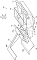
- the caster 26 is composed of a pair of steering casters 40, a pair of free casters 42, and a pair of constantly grounded casters 44. That is, the carriage portion 17 has a total of six casters 26.
- each caster 26 is arranged in the order of the always-grounded caster 44, the steering caster 40, and the free caster 42 from the front to the rear of the carriage section 17, that is, from the front to the rear of the mobile radiography apparatus 10. ing.
- a pair of always-ground casters 44 are provided at both ends in the width direction (Y direction in FIG. 6) of the carriage portion 17 in front of the carriage portion 17.
- the pair of steering casters 40 are provided at substantially the center of the carriage portion 17 in the front-rear direction, that is, at both ends of the carriage portion 17 in the width direction (Y direction in FIG. 6) at the position of the center of gravity in the front-rear direction of the entire mobile radiography apparatus 10.
- Each part is provided.
- a pair of free casters 42 are provided at both ends in the width direction (Y direction in FIG. 6) of the carriage portion 17 behind the carriage portion 17.
- Each of the pair of free casters 42 rotates independently about the axle D1 extending in the horizontal direction (Y direction) and turns independently about the turning axis H1 extending in the vertical direction (Z direction). Further, the pair of free casters 42 are not connected to the steering wheel 48 provided on the main body portion 16 and will be described later, and the steering angle changes subordinately according to the direction of the force applied to the bogie portion 17.
- the pair of constantly grounded casters 44 are casters that are constantly grounded on the floor 46 shown in FIG.
- “always” means that the vehicle is grounded in both the first grounded state and the second grounded state, which will be described later. Therefore, for example, when the carriage portion 17 is tilted, the always-ground caster 44 is also separated from the floor 46.
- the always-grounded caster 44 has the same configuration as the free caster 42. That is, each of the pair of constantly grounded casters 44 rotates independently about the axle D2 extending in the horizontal direction (Y direction) and independently centering on the turning shaft H2 extending in the vertical direction (Z direction). Turn. Then, similarly to the free caster 42, the steering angle changes subordinately according to the direction of the force applied to the bogie portion 17.
- Each of the pair of steering casters 40 rotates independently around the axle D3 extending in the horizontal direction (Y direction). Further, the pair of steering casters 40 are connected to a steering 48, which will be described later, provided in the main body 16, and a steering angle is given by operating the steering 48. By operating the steering wheel 48, the pair of steering casters 40 are both interlocked to turn in the same direction.
- the main body 16 is provided with a steering 48 that gives a steering angle to the steering casters 40.
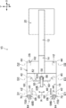
- the steering 48 includes a lever 50 and a link mechanism 52 that transmits the rotation of the lever 50 to a pair of steering casters 40.
- the lever 50 is attached to the main body 16 via, for example, a pedestal 54 fixed to the upper surface of the main body 16.
- the lever 50 is a grip that is erected on the pedestal 54 and is rotatably attached to the pedestal 54 about an axis, and a grip that extends radially outward (horizontally) from the rotary shaft 50A.
- a part 50B and a part 50B are provided. The operator operates the lever 50 by grasping the grip portion 50B by hand and rotating it around the axis of the rotating shaft 50A.
- the lever 50 has a range of about 90 ° to the left and right about the axis of the rotation axis 50A from the reference position where the extension direction of the grip portion 50B of the lever 50 is the front-back direction (X direction) of the mobile radiography apparatus 10. It is rotatable.
- the rotation angle of the lever 50 can be adjusted to any angle within the rotatable range.
- the link mechanism 52 connects the shaft 56 whose upper end is fixed to the rotating shaft 50A of the lever 50, the pinion 58 fixed to the lower end of the shaft 56, the rack 60 that meshes with the pinion 58, and the rack 60 and the steering caster 40. It is equipped with a tie rod 62.
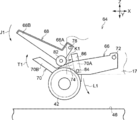
- the carriage portion 17 is provided with a switching mechanism 64.
- the switching mechanism 64 selectively switches between the first ground contact state and the second ground contact state by moving the free caster 42 up and down with respect to the steering caster 40.
- the first ground contact state is a ground contact state in which the free caster 42 is separated from the floor 46 and the steering caster 40 is grounded on the floor 46.
- the second ground contact state is a ground contact state in which the free caster 42 is grounded to the floor 46 and the steering caster 40 is separated from the floor 46, as shown in FIG.
- the switching mechanism 64 includes a movable frame 66 and a first pedal 68 and a second pedal 70 as pedals for raising and lowering the free caster 42.
- the front end portion (front end portion) of the movable frame 66 is rotatably fixed around the axis of the shaft 72 with respect to the shaft 72 via a bearing portion (not shown).
- the shaft 72 extends in the width direction (Y direction) of the carriage portion 17 shown in FIG. 4, and both ends in the axial direction are fixed to the carriage portion 17.
- a free caster 42 is attached to the rear end portion (rear end portion) of the movable frame 66. That is, the free caster 42 is attached to the carriage portion 17 via the movable frame 66.
- the movable frame 66 rotates about a shaft 72 provided at the front end portion. Due to the rotation about the shaft 72, the rear end portion of the movable frame 66 moves up and down in the vertical direction (Z direction) while drawing an arc. The rear end portion of the movable frame 66 is urged upward in the vertical direction (Z direction) by an urging member (not shown).
- a pair of slopes 74 are formed on the upper surface of the rear end portion of the movable frame 66.
- the height of the pair of slopes 74 gradually increases from the rear end portion to the front end portion of the movable frame 66.
- a groove 76 is formed between the pair of slopes 74.
- the first pedal 68 includes a base portion 68A provided at the front end portion (front end portion) of the first pedal 68 and a tread surface 68B provided at the rear end portion (front end portion) of the first pedal 68. , Is equipped.
- the base portion 68A is rotatably fixed around the axis of the shaft 78 with respect to the shaft 78 via a bearing portion (not shown).
- the shaft 78 extends in the width direction (Y direction) of the carriage portion 17 shown in FIG. 4, and both ends in the axial direction are fixed to the carriage portion 17.
- a bearing shaft 80 extending in parallel with the shaft 78 is fixed to the lower part of the shaft 78 in the base portion 68A of the first pedal 68.
- a pair of bearings 82 are rotatably fixed to the bearing shaft 80 around the axis of the bearing shaft 80.
- the pair of bearings 82 can rotate coaxially with each other, and are provided at intervals in the axial direction of the bearing shaft 80. Further, the pair of bearings 82 are movably mounted on the pair of slopes 74 formed on the movable frame 66 along the slopes 74.
- the tread 68B of the first pedal 68 is integrally fixed to the base 68A, and can rotate around the axis of the shaft 78 together with the base 68A. Further, as shown in FIGS. 4 to 6, the tread 68B of the first pedal 68 projects to the rear side of the bogie portion 17. As a result, the operator can step on the tread 68B of the first pedal 68 from the outside of the mobile radiography apparatus 10.
- the second pedal 70 includes a base portion 70A provided at the front end portion (front end portion) of the second pedal 70 and a rear end portion (front side end portion) of the second pedal 70. It is provided with a tread 70B provided at the end).
- the base 70A is arranged in a groove 76 formed between a pair of slopes 74 of the movable frame 66, and is rotatably fixed around the axis of the shaft 84 with respect to the shaft 84 via a bearing portion (not shown). There is.
- the shaft 84 extends in the width direction (Y direction) of the carriage portion 17 shown in FIG. 4, and both ends in the axial direction are fixed to the movable frame 66.
- a contact portion 86 is provided on the upper portion of the shaft 84 in the base portion 70A of the second pedal 70.
- the contact portion 86 projects upward from the groove 76 of the movable frame 66 in the vertical direction (Z direction) and is located between the pair of slopes 74. As a result, the contact portion 86 can come into contact with the pair of bearings 82 that move on the pair of slopes 74.
- the tread 70B of the second pedal 70 is integrally fixed to the base 70A, and can rotate around the axis of the shaft 84 together with the base 70A. Further, as shown in FIG. 6, the tread surface 70B of the second pedal 70 projects to the rear side of the bogie portion 17, similarly to the tread surface 68B of the first pedal 68. As a result, the operator can step on the tread surface 70B of the second pedal 70 from the outside of the mobile radiography apparatus 10 with his / her foot.
- the operator steps on the tread 68B of the first pedal 68 with his / her foot to lower the free caster 42 with respect to the steering caster 40.
- the first pedal 68 moves in the arrow J1 direction around the axis of the shaft 78 (counterclockwise in FIG. 10). Rotate to.
- the bearing 82 provided at the base portion 68A of the first pedal 68 moves forward (in the direction of arrow K1 in FIG. 10) along the slope 74 of the movable frame 66.
- the height of the slope 74 gradually increases from the rear end portion to the front end portion of the movable frame 66. Therefore, when the bearing 82 moves forward, the slope 74 is pushed downward by the bearing 82 in the vertical direction (Z direction). As a result, the movable frame 66 rotates around the axis of the shaft 72 in the direction of arrow L1 (counterclockwise in FIG. 10), so that the rear end portion of the movable frame 66 is lowered.
- a free caster 42 is attached to the lower surface of the rear end of the movable frame 66. Therefore, when the rear end portion of the movable frame 66 is lowered, the free caster 42 is lowered with respect to the bogie portion 17, that is, the steering caster 40 shown in FIG. As a result, as shown in FIGS. 5 and 11, the free caster 42 is in contact with the floor 46, and the free caster 42 is located below the steering caster 40. As a result, the steering caster 40 is separated from the floor 46.
- the operator steps on the tread surface 70B of the second pedal 70 with his / her foot to raise the free caster 42 with respect to the steering caster 40.
- the second pedal 70 moves in the arrow T2 direction around the axis of the shaft 84 (counterclockwise in FIG. 11). Rotate to.
- the contact portion 86 provided on the base portion 70A of the second pedal 70 also rotates around the axis of the shaft 84 in the direction of arrow T2.
- a free caster 42 is attached to the lower surface of the rear end of the movable frame 66. Therefore, as the rear end portion of the movable frame 66 rises, the free caster 42 rises with respect to the bogie portion 17, that is, the steering caster 40 shown in FIG. As a result, as shown in FIGS. 4 and 10, the free caster 42 is separated from the floor 46, and the free caster 42 is located above the steering caster 40. As a result, the steering caster 40 comes into contact with the floor 46.
- a pair of handles 88 for pushing and pulling the main body 16 (dolly 17) are fixed to the upper surface of the main body 16.
- the handle 88 is, for example, a bar handle composed of a cylindrical bar having a substantially circular cross section.
- the handle 88 extends in the front-rear direction (X direction) of the main body 16, and both ends in the extending direction are fixed to the upper surface of the main body 16. Further, as shown in FIG. 6, the pair of handles 88 are provided at both ends in the width direction (Y direction in FIG. 6) behind the main body portion 16.
- the pair of handles 88 are each gripped and pushed and pulled by the operator when the mobile radiography apparatus 10 is moved.
- the shape and fixed position of the handle 88 are not limited to the embodiments, and a shape that is easy to grip and a position that is easy to grip are appropriately selected.
- the steering 48 is provided with a steering lock mechanism 90 that locks the operation by the steering 48 in the second ground contact state in which the steering caster 40 shown in FIG. 4 is separated from the floor 46. ing.
- the steering lock mechanism 90 locks the rotation of the lever 50 constituting the steering 48 with respect to the pedestal 54, as an example.
- the steering lock mechanism 90 includes a pin hole 92A formed on the upper surface of the pedestal 54, a pin hole 92B formed in a flange portion 94 which is a contact portion between the lever 50 and the pedestal 54, and a lever 50.
- the lock pin 96 is inserted into the pin hole 92B of the above.
- the pin hole 92B of the flange portion 94 of the lever 50 has substantially the same diameter as the pin hole 92A of the pedestal 54, and penetrates the flange portion 94 in the vertical direction (Z direction).
- the grip portion 50B of the lever 50 is at a reference position (the position where the extension direction of the grip portion 50B of the lever 50 is the front-rear direction (X direction) of the mobile radiography apparatus 10). Is formed at a position communicating with the pin hole 92A of the pedestal 54.
- the lever 50 can rotate about the axis of the rotating shaft 50A with respect to the pedestal 54.
- the steering caster 40 (see FIG. 4) can be operated by the lever 50 constituting the steering 48.
- the lock pin 96 may be manually inserted into the pin hole 92A, or may be electrically inserted into the pin hole 92A by using, for example, a solenoid (not shown).
- the steering caster 40 whose steering angle is given by the operation of the steering 48 and the free caster whose steering angle changes subordinately according to the direction of the force applied to the carriage portion 17. 42 and are provided in the carriage portion 17. Further, the switching mechanism 64 makes it possible to selectively switch between the first grounded state and the second grounded state of the caster 26.
- the operability of the bogie portion 17 can be changed according to the usage scene by selectively switching the ground contact state of the free caster 42 and the steering caster 40 by the switching mechanism 64.
- the traveling direction of the carriage portion 17 can be fixed. If the traveling direction of the trolley portion 17 can be fixed, it is convenient to perform continuous shooting while moving the shooting position.
- the carriage portion 17 can be stably moved along the body axis direction of the subject H. Since the steering angle of the steering caster 40 can be fixed by operating the steering 48, the bogie portion 17 does not sway when the bogie portion 17 is moved, and the traveling direction is stable.
- the bogie portion 17 can be turned in a small turn.
- the orientation of the trolley portion 17 can be changed in a narrow space. Therefore, it is easy to use when the mobile radiography apparatus 10 is used in a narrow hospital room.
- the switching mechanism 64 switches the ground contact state between the free caster 42 and the steering caster 40
- the configuration is simple.
- a method of switching between an enabled state and an invalid state of the input of the operating force from the steering 48 to the steering caster 40 can be considered while the steering caster 40 is in contact with the ground.
- the invalid state is, in short, a state in which the steering caster 40 functions as a free caster.
- the mechanism for switching the ground contact state is easier to simplify the configuration than the mechanism for switching between the valid state and the invalid state of the input of the operating force from the steering 48.
- the switching mechanism 64 switches between the first ground contact state and the second ground contact state by moving the free caster 42 up and down with respect to the steering caster 40.
- the weight of the steering caster 40 is heavier than that of the free caster 42.
- the switching mechanism 64 by raising and lowering the free caster 42 side by the switching mechanism 64, the ground contact state of the caster 26 can be easily switched with a light force as compared with the configuration in which the steering caster 40 side is raised and lowered.
- the switching mechanism 64 has a first pedal 68 and a second pedal 70 as pedals for raising and lowering the free caster 42. Therefore, since the free caster 42 can be raised and lowered by stepping on the first pedal 68 or the second pedal 70 with a foot, it is possible to switch the ground contact state of the caster 26 while manually operating the mobile radiography apparatus 10. It becomes.
- the pedal is composed of two pedals, a first pedal 68 and a second pedal 70, and when one of the pedals is lowered, the other is raised.
- the free caster 42 is lowered by lowering the pedal, and the free caster 42 is raised by raising the pedal.
- the work of pulling up the pedal has a larger load than the work of pushing down the pedal.
- both the operation of raising the free caster 42 and the operation of lowering the free caster 42 can be realized by stepping on (pushing down) the pedal. .. Therefore, it becomes easy to switch the ground contact state of the caster 26.
- the bogie portion 17 is provided with a constant grounding caster 44 that is grounded to the floor 46 in both the first grounding state and the second grounding state. There is.
- the bogie portion 17 can be stably driven. Further, when the ground contact state of the free caster 42 and the steering caster 40 is switched, the posture of the carriage portion 17 is suppressed from becoming unstable.
- the always-grounded casters 44, the steering casters 40, and the free casters 42 are arranged in this order from the front to the rear of the bogie portion 17.
- the steering casters 40 By arranging the steering casters 40 between the constantly grounded casters 44 and the free casters 42 in this way, the steering casters 40 can be arranged at a position close to the position of the center of gravity of the main body portion 16. As a result, it is possible to prevent the posture of the main body 16 from becoming unstable when the steering 48 is operated.
- the steering caster 40 is arranged at the position of the center of gravity of the entire mobile radiography apparatus 10 in the front-rear direction of the carriage portion 17. As a result, it is possible to further prevent the posture of the main body 16 from becoming unstable when the steering 48 is operated.
- the arm 12 of the mobile radiography apparatus 10 of the present embodiment has two end portions, an irradiation portion 18 is provided at one end, and an image receiving portion 20 is provided at the other end. Therefore, the irradiation unit 18 and the image receiving unit 20 can be integrally held by the arm 12. Thereby, for example, it is possible to take a picture while moving the carriage portion 17 in the body axis direction of the subject H during the operation.
- the steering lock mechanism 90 for locking the operation by the steering 48 is provided. Therefore, for example, in the second ground contact state where the steering caster 40 is separated from the floor 46, the steering lock mechanism 90 makes the lever 50 non-rotatable with respect to the pedestal 54 (main body 16), thereby rotating the steering caster 40. It can be impossible. As a result, it is possible to prevent the steering caster 40 from moving and the posture of the mobile radiography apparatus 10 from becoming unstable when the main body 16 is moved by the free caster 42.
- the handle 88 for pushing and pulling the bogie portion 17 is provided separately from the lever 50 constituting the steering 48. In this way, by providing the handle 88 separately from the lever 50, it is easy to operate when the carriage portion 17 is driven by the free caster 42.
- the constantly grounded caster 44 is a caster whose steering angle changes subordinately like the free caster 42.
- the constant ground caster 44 may be a fixed caster that cannot turn.
- the bogie portion 17 does not necessarily have to be always provided with a grounding caster 44.
- the always-ground casters 44 are not provided, for example, by providing three or more steering casters 40 and three or more free casters 42 on the carriage portion 17, the carriage portion 17 can be stably traveled.
- the arrangement of each caster 26 is not limited to the above embodiment, and the steering caster 40 may be arranged behind the constantly grounded caster 44 and the free caster 42.
- the free caster 42 is raised and lowered by the switching mechanism 64, but the steering caster 40 may be raised and lowered by the switching mechanism 64.
- the handle 88 is provided on the upper surface of the main body portion 16.
- the mobile radiography apparatus 10 may be moved by pushing and pulling the lever 50 of the steering wheel 48 or directly pushing and pulling the main body 16 without providing the handle 88.
- the link mechanism 52 of the steering 48 is composed of the shaft 56, the pinion 58, the rack 60, and the tie rod 62, but the configuration of the link mechanism 52 is not limited to the above embodiment and is not limited to the above embodiment. It is possible to use the link mechanism of.
- the steering lock mechanism 90 is configured to lock the rotation of the lever 50 constituting the steering 48.
- the steering lock mechanism 90 may be configured to lock the rotation of any of the mechanisms constituting the steering 48 and the steering caster 40, and may be, for example, a stopper that locks the rotation of the steering caster 40.
- the steering caster 40 can be allowed to move when the main body 16 is moved by the free caster 42, it is not always necessary to provide the steering lock mechanism 90.
- a C arm having a C-shaped side surface has been described as an example, but a U-arm having a U-shaped side surface may also be used.
- the arm 12 may be an I-arm having an I-shaped side surface provided with only the irradiation portion 18 at one end.
- the irradiation unit 18 and the image receiving unit 20 are provided at both ends of the arm 12, but the arm 12 does not necessarily have to be provided with the image receiving unit 20, and at least only the irradiation unit 18 is provided. It suffices if it is done.
- X-rays have been described as an example of radiation, but the radiation is not limited to X-rays and may be ⁇ -rays or the like.
Abstract
A radiography device comprising: an irradiation unit that emits radiation; a movable carriage unit on which the irradiation unit is installed; a steering caster which is provided on the carriage unit and connected to a steering wheel, and to which a steering angle is given by a steering wheel operation; a free caster which is provided on the carriage unit and is not connected to the steering wheel, and the steering angle of which changes passively according to the direction of the force applied to the carriage unit; and a switching mechanism that selectively switches between a first ground contact state in which the free caster is separated from the floor and the steering caster is brought into contact with the floor, and a second ground contact state in which the free caster is brought into contact with the floor and the steering caster is separated from the floor.
Description
本開示は、移動型放射線撮影装置に関する。
This disclosure relates to a mobile radiography apparatus.
放射線を照射する照射部と、走行可能な台車部とを有する移動型放射線撮影装置が知られている(特開2011-87923号公報参照)。台車部は、複数のキャスターが設けられており、照射部が設けられたアームを支持する支持部及び本体部が搭載される。
A mobile radiography apparatus having an irradiation unit for irradiating radiation and a traveling carriage portion is known (see JP-A-2011-87923). The dolly portion is provided with a plurality of casters, and a support portion and a main body portion that support an arm provided with an irradiation portion are mounted.
特開2011-87923号公報に記載の移動型放射線撮影装置(X線撮影装置)の台車部には、ステアリングキャスター(主輪)とフリーキャスター(補助輪)との2種類のキャスターが設けられている。ステアリングキャスターは、ステアリングが結合されたキャスターであり、ステアリングの操作によって舵角が与えられる。これにより、ステアリングの操作によって台車部の進行方向を固定することが可能となる。フリーキャスターは、ステアリングと連結されておらず、台車部に付与される力に応じて従動的に舵角が変化する。
Two types of casters, a steering caster (main wheel) and a free caster (training wheel), are provided on the carriage portion of the mobile radiography apparatus (X-ray imaging apparatus) described in Japanese Patent Application Laid-Open No. 2011-87923. There is. The steering caster is a caster to which the steering is combined, and the steering angle is given by the operation of the steering. This makes it possible to fix the traveling direction of the bogie portion by operating the steering wheel. The free caster is not connected to the steering wheel, and the steering angle changes subordinately according to the force applied to the bogie.
このような移動型放射線撮影装置は、撮影室で使用される他、病室及び手術室で使用される場合がある。撮影室への移動が困難な患者を撮影する場合には、移動型放射線撮影装置は患者の病室内に運び込まれて病室内で使用される。また、手術中の患者の処置対象部位を動画撮影する場合には、手術室内に運び込まれて手術室内で使用される。こうした複数の使用場面で移動型放射線撮影装置を使用することを考えた場合、各使用場面に応じて台車部に求められる操作性は変化する。
Such a mobile radiography device may be used in a hospital room or an operating room in addition to being used in a radiography room. When photographing a patient who is difficult to move to the imaging room, the mobile radiography apparatus is carried into the patient's room and used in the patient's room. In addition, when a moving image of a treatment target site of a patient undergoing surgery is taken, it is carried into the operating room and used in the operating room. When considering the use of the mobile radiography apparatus in such a plurality of usage situations, the operability required for the trolley portion changes according to each usage scene.
例えば、病室は、撮影室と比べて狭いため、撮影室と比較してより小回りが利くことが求められる。また、ベッドなどの障害物が多い狭い病室内で使用する場合は、わざわざステアリングを操作することなく、様々な方向から移動型放射線撮影装置を押し引きすることにより、台車部の向きを簡単に変化させたいという要望がある。一方、手術中においては、例えば、患者の体軸に沿って撮影位置を順次移動させながら撮影を行う場合もある。このような場合は、台車部がふらつくと適切な撮影を行うことができないため、ステアリングの位置を固定することによって台車部の進行方向を固定させたいという要望がある。
For example, since the hospital room is smaller than the imaging room, it is required to have a smaller turn than the imaging room. In addition, when using in a narrow hospital room with many obstacles such as a bed, the orientation of the trolley can be easily changed by pushing and pulling the mobile radiography device from various directions without having to bother to operate the steering wheel. There is a request to let me do it. On the other hand, during surgery, for example, imaging may be performed while sequentially moving the imaging position along the body axis of the patient. In such a case, if the bogie portion fluctuates, it is not possible to take an appropriate picture. Therefore, there is a demand to fix the traveling direction of the bogie portion by fixing the steering position.
特開2011-87923号公報に記載の移動型放射線撮影装置は、ステアリングキャスターが常時接地されているため、台車部の進行方向はステアリングの位置によって固定されてしまう。そのため、ステアリングの操作をしないと台車部の向きを変化させにくいため、台車部の小回りが利かず、狭い病室内で使用する場合には使い勝手がよくない。一方、ステアリングキャスターを設けずに、フリーキャスターのみの台車部を用いた場合は、小回りは利く反面、台車部の進行方向を固定させたい場合には使い勝手がよくない。このように、使用場面に応じて台車部に求められる操作性は変化する。
In the mobile radiography apparatus described in Japanese Patent Application Laid-Open No. 2011-87923, since the steering caster is always in contact with the ground, the traveling direction of the carriage portion is fixed by the position of the steering wheel. Therefore, since it is difficult to change the orientation of the trolley portion without operating the steering wheel, the trolley portion does not have a small turn, and it is not convenient when used in a narrow hospital room. On the other hand, when the bogie portion with only free casters is used without providing the steering casters, the small turning is effective, but the usability is not good when the traveling direction of the bogie portion is to be fixed. In this way, the operability required of the bogie changes depending on the usage situation.
本開示に係る技術は、使用場面に応じて台車部の操作性を変化させることが可能な移動型放射線撮影装置を提供する。
The technology according to the present disclosure provides a mobile radiography apparatus capable of changing the operability of the trolley portion according to the usage situation.
本開示の第1態様に係る移動型放射線撮影装置は、放射線を照射する照射部と、照射部が搭載され、かつ、走行可能な台車部と、台車部に設けられ、かつ、ステアリングと連結され、ステアリングの操作によって舵角が与えられるステアリングキャスターと、台車部に設けられ、ステアリングと連結されておらず、台車部に加わる力の向きに応じて従動的に舵角が変化するフリーキャスターと、フリーキャスターを床から離間させ、かつ、ステアリングキャスターを床に接地させる第1接地状態と、フリーキャスターを床に接地させ、かつ、ステアリングキャスターを床から離間させる第2接地状態と、を選択的に切り替える切り替え機構と、を備えている。
The mobile radiography apparatus according to the first aspect of the present disclosure is provided with an irradiation unit for irradiating radiation, a carriage unit on which the irradiation unit is mounted and capable of traveling, a carriage portion, and is connected to a steering wheel. , Steering casters whose steering angle is given by steering operation, and free casters which are provided on the bogie and are not connected to the steering wheel and whose steering angle changes subordinately according to the direction of the force applied to the bogie. Selectively select a first ground contact state in which the free casters are separated from the floor and the steering casters are grounded on the floor, and a second ground contact state in which the free casters are grounded on the floor and the steering casters are separated from the floor. It is equipped with a switching mechanism for switching.
上記構成によれば、切り替え機構によってフリーキャスター及びステアリングキャスターの接地状態を選択的に切り替えることで、使用場面に応じて台車部の操作性を変化させることができる。
According to the above configuration, the operability of the bogie can be changed according to the usage situation by selectively switching the ground contact state of the free caster and the steering caster by the switching mechanism.
すなわち、台車部の操作性について、フリーキャスターを接地させることで、台車部の小回りが利くようになる一方、ステアリングキャスターを接地させることで、台車部の進行方向を固定することができる。小回りが利くと、狭い病室内で使用する場合には使い勝手がよい。進行方向を固定できると、撮影位置を移動しながら連続的な撮影を行う場合に使い勝手がよい。
That is, regarding the operability of the bogie, by grounding the free casters, the bogie can be turned in a small turn, while by grounding the steering casters, the traveling direction of the bogie can be fixed. If it is easy to turn around, it is easy to use when using it in a small hospital room. If the direction of travel can be fixed, it is convenient when continuous shooting is performed while moving the shooting position.
本開示の第2態様に係る移動型放射線撮影装置は、第1態様に係る移動型放射線撮影装置において、切り替え機構は、フリーキャスターをステアリングキャスターに対して昇降させることにより、第1接地状態と第2接地状態とを切り替える。
The mobile radiography apparatus according to the second aspect of the present disclosure is the mobile radiography apparatus according to the first aspect, in which the switching mechanism raises and lowers the free caster with respect to the steering caster to bring the free caster up and down to the first ground contact state. 2 Switch between the grounded state.
一般的に、ステアリングキャスターは、ステアリングに連結されているため、フリーキャスターに比べて重さが重い。ここで、上記構成によれば、切り替え機構によってフリーキャスター側を昇降させることで、ステアリングキャスター側を昇降させる構成と比較して、軽い力で容易にキャスターの接地状態を切り替えることができる。
Generally, the steering caster is heavier than the free caster because it is connected to the steering wheel. Here, according to the above configuration, by raising and lowering the free caster side by the switching mechanism, the ground contact state of the caster can be easily switched with a light force as compared with the configuration in which the steering caster side is raised and lowered.
本開示の第3態様に係る移動型放射線撮影装置は、第2態様に係る移動型放射線撮影装置において、切り替え機構は、フリーキャスターを昇降させるペダルを有する。
The mobile radiography apparatus according to the third aspect of the present disclosure is the mobile radiography apparatus according to the second aspect, and the switching mechanism has a pedal for raising and lowering the free caster.
上記構成によれば、ペダルを足で踏んでフリーキャスターを昇降させることができるため、移動型放射線撮影装置を手で操作しながらキャスターの接地状態を切り替えることが可能となる。
According to the above configuration, since the free caster can be raised and lowered by stepping on the pedal with the foot, it is possible to switch the ground contact state of the caster while manually operating the mobile radiography apparatus.
本開示の第4態様に係る移動型放射線撮影装置は、第1態様~第3態様のいずれか1つの態様に係る移動型放射線撮影装置において、フリーキャスター及びステアリングキャスターに加えて、第1接地状態及び第2接地状態のいずれにおいても床に接地する常時接地キャスターが設けられている。
The mobile radiography apparatus according to the fourth aspect of the present disclosure is the mobile radiography apparatus according to any one of the first to third aspects, in which the first ground contact state is provided in addition to the free casters and the steering casters. In both the second grounding state and the second grounding state, a constant grounding caster is provided to ground the floor.
上記構成によれば、フリーキャスター及びステアリングキャスターに加えて、常時接地キャスターが設けられているため、フリーキャスター及びステアリングキャスターの一方が床から離間している場合でも、台車部を安定して走行させることができる。また、フリーキャスターとステアリングキャスターの接地状態を切り替える際に、台車部の姿勢が不安定になることも抑制される。
According to the above configuration, in addition to the free casters and the steering casters, the always-grounded casters are provided, so that the bogie portion can be stably driven even when one of the free casters and the steering casters is separated from the floor. be able to. In addition, when switching the ground contact state between the free casters and the steering casters, it is possible to prevent the posture of the bogie from becoming unstable.
本開示の第5態様に係る移動型放射線撮影装置は、第4態様に係る移動型放射線撮影装置において、台車部には、照射部を支持するアームと、照射部を制御する制御部を有する本体部とが搭載されており、常時接地キャスターは、フリーキャスターと同様に従動的に舵角が変化するキャスターであり、アームが設けられている側を台車部の前方、かつ、本体部が設けられている側を台車部の後方とした場合において、台車部の前方から後方にかけて、常時接地キャスター、ステアリングキャスター、及びフリーキャスターの順に配置されている。
The mobile radiography apparatus according to the fifth aspect of the present disclosure is the main body of the mobile radiography apparatus according to the fourth aspect, wherein the carriage portion has an arm for supporting the irradiation portion and a control unit for controlling the irradiation portion. The always-grounded caster is a caster whose steering angle changes subordinately like a free caster, and the side where the arm is provided is in front of the bogie and the main body is provided. When the side facing is the rear of the bogie, the casters are always in contact with the ground, the steering casters, and the free casters from the front to the rear of the bogie.
上記構成によれば、本体部の前後方向において、常時接地キャスターとフリーキャスターの間にステアリングキャスターを配置することで、ステアリングキャスターを本体部の重心位置に近い位置に配置することができる。これにより、ステアリングを操作する際に本体部の姿勢が不安定になることを抑制することができる。
According to the above configuration, by arranging the steering casters between the constantly grounded casters and the free casters in the front-rear direction of the main body portion, the steering casters can be arranged at a position close to the position of the center of gravity of the main body portion. As a result, it is possible to prevent the posture of the main body from becoming unstable when the steering is operated.
本開示の第6態様に係る移動型放射線撮影装置は、第5態様に係る移動型放射線撮影装置において、台車部の前後方向において、ステアリングキャスターは重心位置に配置されている。
The mobile radiography apparatus according to the sixth aspect of the present disclosure is the mobile radiography apparatus according to the fifth aspect, in which the steering casters are arranged at the center of gravity in the front-rear direction of the carriage portion.
上記構成によれば、ステアリングキャスターを移動型放射線撮影装置全体における重心位置に配置することで、ステアリングを操作する際に本体部の姿勢が不安定になることをより抑制することができる。
According to the above configuration, by arranging the steering casters at the position of the center of gravity in the entire mobile radiography apparatus, it is possible to further suppress the posture of the main body from becoming unstable when operating the steering.
本開示の第7態様に係る移動型放射線撮影装置は、第5態様又は第6態様に係る移動型放射線撮影装置において、アームは、2つの端部を有しており、アームの一端には、照射部が設けられており、アームの他端には、照射部から照射され被写体を透過した放射線を受ける受像部が設けられている。
The mobile radiography apparatus according to the seventh aspect of the present disclosure is the mobile radiography apparatus according to the fifth or sixth aspect, wherein the arm has two ends, and one end of the arm has two ends. An irradiation unit is provided, and an image receiving unit that receives radiation emitted from the irradiation unit and transmitted through the subject is provided at the other end of the arm.
上記構成によれば、照射部と受像部とをアームに一体的に保持することが可能である。そのため、例えば、手術中に被写体の体軸方向に台車部を移動させながら、撮影を行うことが可能である。
According to the above configuration, it is possible to integrally hold the irradiation unit and the image receiving unit on the arm. Therefore, for example, it is possible to take a picture while moving the carriage portion in the body axis direction of the subject during the operation.
本開示の第8態様に係る移動型放射線撮影装置は、第1態様~第7態様のいずれか1つの態様に係る移動型放射線撮影装置において、ステアリングキャスターが床から離間する第2接地状態において、ステアリングによる操作をロックするステアリングロック機構を有する。
The mobile radiography apparatus according to the eighth aspect of the present disclosure is the mobile radiography apparatus according to any one of the first to seventh aspects, in a second ground contact state in which the steering caster is separated from the floor. It has a steering lock mechanism that locks the operation by steering.
上記構成によれば、ステアリングキャスターが床から離間している場合に、ステアリングによる操作をロックするステアリングロック機構を有している。これにより、フリーキャスターによって本体部を移動させている際に、ステアリングキャスターが動いて、移動型放射線撮影装置の姿勢が不安定になることを抑制することができる。
According to the above configuration, it has a steering lock mechanism that locks the operation by steering when the steering caster is separated from the floor. As a result, it is possible to prevent the steering caster from moving and the posture of the mobile radiographing apparatus from becoming unstable when the main body is moved by the free casters.
本開示の第9態様に係る移動型放射線撮影装置は、第1態様~第8態様のいずれか1つの態様に係る移動型放射線撮影装置において、台車部を押し引きするためのハンドルが、ステアリングとは別に設けられている。
In the mobile radiography apparatus according to the ninth aspect of the present disclosure, in the mobile radiography apparatus according to any one of the first to eighth aspects, the handle for pushing and pulling the carriage portion is a steering wheel. Is provided separately.
上記構成によれば、ステアリングとは別に台車部を押し引きするためのハンドルを設けることで、フリーキャスターによって台車部を走行させる際に操作しやすい。
According to the above configuration, by providing a handle for pushing and pulling the bogie part separately from the steering wheel, it is easy to operate when the bogie part is driven by the free casters.
本開示に係る技術によれば、使用場面に応じて台車部の操作性を変化させることが可能となる。
According to the technology according to the present disclosure, it is possible to change the operability of the trolley portion according to the usage situation.
以下、本開示の実施形態の一例に係る移動型放射線撮影装置について、図面を参照して説明する。なお、図中において、矢印Xは移動型放射線撮影装置の前後方向、矢印Yは移動型放射線撮影装置の幅方向、矢印Zは鉛直方向を指す。
Hereinafter, the mobile radiography apparatus according to an example of the embodiment of the present disclosure will be described with reference to the drawings. In the figure, the arrow X indicates the front-back direction of the mobile radiography apparatus, the arrow Y indicates the width direction of the mobile radiography apparatus, and the arrow Z indicates the vertical direction.
(移動型放射線撮影装置の全体構成)
図1に示す本実施形態の移動型放射線撮影装置10は、被写体Hの放射線画像を撮影する装置である。移動型放射線撮影装置10は、例えば、被写体Hの動画撮影および静止画撮影が可能である。動画撮影は、例えば、手術の際に被写体Hの処置対象部位を動画で表示する場合(透視撮影等とも呼ばれる)に行われる。動画撮影においては、例えば、移動型放射線撮影装置10とは別に設置された図示しないモニタに被写体Hの動画が表示される。もちろん、撮影した動画のデータを移動型放射線撮影装置10のメモリ内に保存することも可能である。また、静止画撮影の場合も、撮影した静止画をモニタに表示したり、移動型放射線撮影装置10内のメモリ内に保存したりすることが可能である。 (Overall configuration of mobile radiography equipment)
Themobile radiography apparatus 10 of the present embodiment shown in FIG. 1 is an apparatus for photographing a radiographic image of a subject H. The mobile radiation photographing apparatus 10 can, for example, take a moving image and a still image of the subject H. The moving image shooting is performed, for example, when displaying the treatment target site of the subject H as a moving image (also referred to as fluoroscopic photography or the like) during surgery. In moving image shooting, for example, a moving image of the subject H is displayed on a monitor (not shown) installed separately from the mobile radiation photographing device 10. Of course, it is also possible to store the captured moving image data in the memory of the mobile radiography apparatus 10. Further, in the case of still image shooting, it is possible to display the shot still image on the monitor and save it in the memory in the mobile radiography apparatus 10.
図1に示す本実施形態の移動型放射線撮影装置10は、被写体Hの放射線画像を撮影する装置である。移動型放射線撮影装置10は、例えば、被写体Hの動画撮影および静止画撮影が可能である。動画撮影は、例えば、手術の際に被写体Hの処置対象部位を動画で表示する場合(透視撮影等とも呼ばれる)に行われる。動画撮影においては、例えば、移動型放射線撮影装置10とは別に設置された図示しないモニタに被写体Hの動画が表示される。もちろん、撮影した動画のデータを移動型放射線撮影装置10のメモリ内に保存することも可能である。また、静止画撮影の場合も、撮影した静止画をモニタに表示したり、移動型放射線撮影装置10内のメモリ内に保存したりすることが可能である。 (Overall configuration of mobile radiography equipment)
The
図1に示すように、移動型放射線撮影装置10は、側面形状がC字形状(円弧形状)とされたアーム12(Cアーム等と呼ばれる)と、支持部14が取り付けられる本体部16と、を有している。アーム12、支持部14、及び本体部16は、台車部17に搭載されている。なお、以下において、移動型放射線撮影装置10におけるアーム12が設けられている側を移動型放射線撮影装置10の前方、本体部16が設けられている側を移動型放射線撮影装置10の後方とする。
As shown in FIG. 1, the mobile radiography apparatus 10 includes an arm 12 (called a C arm or the like) having a C-shaped (arc-shaped) side surface, and a main body 16 to which a support portion 14 is attached. have. The arm 12, the support portion 14, and the main body portion 16 are mounted on the carriage portion 17. In the following, the side of the mobile radiography apparatus 10 where the arm 12 is provided is the front of the mobile radiography apparatus 10, and the side where the main body 16 is provided is the rear of the mobile radiography apparatus 10. ..
(アームの構成)
アーム12は2つの端部を有しており、アーム12の一端には照射部18が設けられ、他端には受像部20が設けられている。アーム12は、照射部18と受像部20とを対向する姿勢で保持することが可能である。照射部18と受像部20との間には被写体H及び被写体Hが仰臥される寝台Sを挿入可能な間隔が確保されている。なお、以下、アーム12の側面視(図1においてY方向から見る方向)にて、照射部18及び受像部20が設けられている方向をアーム12の前方、支持部14側をアーム12の後方と呼ぶことがある。 (Arm configuration)
Thearm 12 has two end portions, an irradiation portion 18 is provided at one end of the arm 12, and an image receiving portion 20 is provided at the other end. The arm 12 can hold the irradiation unit 18 and the image receiving unit 20 in a facing posture. A space is secured between the irradiation unit 18 and the image receiving unit 20 so that the subject H and the sleeper S on which the subject H is lying can be inserted. Hereinafter, in the side view of the arm 12 (the direction viewed from the Y direction in FIG. 1), the direction in which the irradiation unit 18 and the image receiving unit 20 are provided is the front of the arm 12, and the support 14 side is the rear of the arm 12. May be called.
アーム12は2つの端部を有しており、アーム12の一端には照射部18が設けられ、他端には受像部20が設けられている。アーム12は、照射部18と受像部20とを対向する姿勢で保持することが可能である。照射部18と受像部20との間には被写体H及び被写体Hが仰臥される寝台Sを挿入可能な間隔が確保されている。なお、以下、アーム12の側面視(図1においてY方向から見る方向)にて、照射部18及び受像部20が設けられている方向をアーム12の前方、支持部14側をアーム12の後方と呼ぶことがある。 (Arm configuration)
The
図2Aに示すように、アーム12は、支持部14に設けられた軌道部22Bに対して、軸線M(Y軸と平行な軸線)を中心として軌道回転可能とされている。また、アーム12は、本体部16に設けられた軸受け部23に対して、軸線N(X軸と平行な軸線)を中心として軸回転可能とされている。
As shown in FIG. 2A, the arm 12 can orbitally rotate about the axis M (the axis parallel to the Y axis) with respect to the orbital portion 22B provided on the support portion 14. Further, the arm 12 is rotatable about an axis N (an axis parallel to the X axis) with respect to the bearing portion 23 provided on the main body portion 16.
具体的には、軌道部22Bは、アーム12の円弧と同じ半径を持つ円弧形状をしている。一方、アーム12の外周部には、軌道部22Bに嵌合する嵌合部22Aが設けられている。嵌合部22Aは、アーム12の形状に沿った円弧形状をしている。軌道部22Bは、例えば溝形状であり、凸状の嵌合部22Aが嵌合する。
Specifically, the track portion 22B has an arc shape having the same radius as the arc of the arm 12. On the other hand, a fitting portion 22A that fits into the track portion 22B is provided on the outer peripheral portion of the arm 12. The fitting portion 22A has an arc shape that follows the shape of the arm 12. The track portion 22B has, for example, a groove shape, and a convex fitting portion 22A is fitted.
図2Aに示すように、アーム12に形成された嵌合部22Aが支持部14に形成された軌道部22Bに沿って摺動する。これにより、アーム12は、アーム12の円弧中心の軸線Mを回転中心として、支持部14及び本体部16に対して軌道回転可能とされている。
As shown in FIG. 2A, the fitting portion 22A formed on the arm 12 slides along the track portion 22B formed on the support portion 14. As a result, the arm 12 can orbitally rotate with respect to the support portion 14 and the main body portion 16 with the axis M at the center of the arc of the arm 12 as the center of rotation.
すなわち、図2B及び図2Cに示すように、アーム12を軸線M回りに矢印M1方向(図2Bにおける反時計回り)及び矢印M2方向(図2Cにおける時計回り)にそれぞれ軌道回転させることが可能とされている。これにより、アーム12の両端に設けられた照射部18及び受像部20を対向させた姿勢で被写体H(図1参照)の体軸(Y軸と平行な軸)回りに回転させることができる。
That is, as shown in FIGS. 2B and 2C, the arm 12 can be orbitally rotated around the axis M in the direction of arrow M1 (counterclockwise in FIG. 2B) and in the direction of arrow M2 (clockwise in FIG. 2C), respectively. Has been done. As a result, the irradiation unit 18 and the image receiving unit 20 provided at both ends of the arm 12 can be rotated around the body axis (axis parallel to the Y axis) of the subject H (see FIG. 1) in a posture of facing each other.
また、図2Aに示すように、アーム12には、移動型放射線撮影装置10の前後方向(X方向)に延びる支持軸24の一端が固定されている。この支持軸24の他端は、軸受け部23を介して本体部16に支持されている。支持軸24が軸受け部23に対して軸線Nを中心に回転することにより、図3A~図3Cに示すように、支持軸24の軸線Nを回転中心として、アーム12及び支持部14が本体部16に対して軸回転可能とされている。
Further, as shown in FIG. 2A, one end of a support shaft 24 extending in the front-rear direction (X direction) of the mobile radiography apparatus 10 is fixed to the arm 12. The other end of the support shaft 24 is supported by the main body portion 16 via a bearing portion 23. As the support shaft 24 rotates about the axis N with respect to the bearing portion 23, as shown in FIGS. 3A to 3C, the arm 12 and the support portion 14 have the main body portion with the axis N of the support shaft 24 as the center of rotation. It is said that the axis can be rotated with respect to 16.
すなわち、図3B及び図3Cに示すように、アーム12を軸線N回りに矢印N1方向(図3Bにおける反時計回り)又は矢印N2方向(図3Cにおける時計回り)に軸回転させることが可能とされている。これにより、アーム12の両端に設けられた照射部18及び受像部20の被写体H(図1参照)に対する上下方向(Z軸方向)の位置を反転させることができる。
That is, as shown in FIGS. 3B and 3C, it is possible to rotate the arm 12 around the axis N in the direction of arrow N1 (counterclockwise in FIG. 3B) or in the direction of arrow N2 (clockwise in FIG. 3C). ing. As a result, the positions of the irradiation unit 18 and the image receiving unit 20 provided at both ends of the arm 12 in the vertical direction (Z-axis direction) with respect to the subject H (see FIG. 1) can be reversed.
ここで、図3Aに示す照射部18が受像部20より上に配置されたアーム12の姿勢は、照射部18に含まれる放射線管32(図1参照)が被写体Hの上方に位置する。このため、この姿勢はオーバーチューブ姿勢などと呼ばれる。一方、図3Cに示す照射部18が受像部20より下に配置されたアーム12の姿勢は、放射線管32が被写体Hの下方に位置する。このため、この姿勢はアンダーチューブ姿勢と呼ばれる。
Here, in the posture of the arm 12 in which the irradiation unit 18 shown in FIG. 3A is arranged above the image receiving unit 20, the radiation tube 32 (see FIG. 1) included in the irradiation unit 18 is located above the subject H. Therefore, this posture is called an overtube posture or the like. On the other hand, in the posture of the arm 12 in which the irradiation unit 18 shown in FIG. 3C is arranged below the image receiving unit 20, the radiation tube 32 is located below the subject H. For this reason, this posture is called the undertube posture.
オーバーチューブ姿勢は、アンダーチューブ姿勢と比較して、照射部18と被写体H(図1参照)との間の距離を広くとることができる。これにより、オーバーチューブ姿勢では、比較的広範な領域を撮影することが可能である。このため、オーバーチューブ姿勢は、主に被写体Hの静止画撮影時に用いられる。一方、アンダーチューブ姿勢は、照射部18から照射される放射線が寝台S等によって一部遮蔽される。これにより、アンダーチューブ姿勢では、被写体H(図1参照)の周囲にいる術者又は操作者等(図示せず)の被ばく量を低減することができる。このため、アンダーチューブ姿勢は、放射線の継続的な照射が行われる、被写体Hの動画撮影時に用いられる。
The overtube posture can have a wider distance between the irradiation unit 18 and the subject H (see FIG. 1) than the undertube posture. This makes it possible to capture a relatively wide area in the overtube posture. Therefore, the overtube posture is mainly used when taking a still image of the subject H. On the other hand, in the undertube posture, the radiation emitted from the irradiation unit 18 is partially shielded by the sleeper S or the like. As a result, in the undertube posture, the exposure dose of the operator, the operator, or the like (not shown) around the subject H (see FIG. 1) can be reduced. Therefore, the undertube posture is used when shooting a moving image of the subject H in which continuous irradiation of radiation is performed.
(本体部の構成)
図1に示すように、移動型放射線撮影装置10の本体部16は、照射部18等の移動型放射線撮影装置10の各部を制御する制御部28と、例えばタッチパネル式の操作パネル30と、を有している。その他、本体部16は、移動型放射線撮影装置10の電源スイッチ等の図示しない各種のスイッチ、移動型放射線撮影装置10の各部に電力を供給する電源回路、及びバッテリ等を備えている。 (Structure of the main body)
As shown in FIG. 1, themain body 16 of the mobile radiography apparatus 10 includes a control unit 28 that controls each part of the mobile radiography apparatus 10 such as the irradiation unit 18, and a touch panel type operation panel 30, for example. Have. In addition, the main body 16 includes various switches (not shown) such as a power switch of the mobile radiography apparatus 10, a power supply circuit for supplying electric power to each part of the mobile radiography apparatus 10, a battery, and the like.
図1に示すように、移動型放射線撮影装置10の本体部16は、照射部18等の移動型放射線撮影装置10の各部を制御する制御部28と、例えばタッチパネル式の操作パネル30と、を有している。その他、本体部16は、移動型放射線撮影装置10の電源スイッチ等の図示しない各種のスイッチ、移動型放射線撮影装置10の各部に電力を供給する電源回路、及びバッテリ等を備えている。 (Structure of the main body)
As shown in FIG. 1, the
操作パネル30は、移動型放射線撮影装置10の各部に操作指示を入力することで各部を操作する操作部として機能するとともに、例えば警告メッセージ、及び受像部20から出力された放射線画像等の各種の情報を表示する表示部として機能する。
The operation panel 30 functions as an operation unit for operating each part by inputting an operation instruction to each part of the mobile radiography apparatus 10, and also has various types such as a warning message and a radiation image output from the image receiving unit 20. It functions as a display unit that displays information.
(制御部の構成)
制御部28は、後述する照射部18の放射線管32に制御信号を送信することで、放射線管32の管電圧、管電流、及び放射線の照射時間等を制御する。制御部28が管電圧を制御することにより、放射線のエネルギーが制御される。また、制御部28が管電流及び照射時間を制御することにより、放射線の線量が制御される。実際には、放射線管32に対しては高電圧が印加されるため、制御部28は、図示しない高電圧発生装置を通じて放射線管32を制御する。撮影に際しては、操作パネル30を通じて、管電圧、管電流及び照射時間などを含む撮影条件が設定される。制御部28は、設定された撮影条件に基づいて照射部18を動作させる。 (Structure of control unit)
Thecontrol unit 28 controls the tube voltage, tube current, radiation irradiation time, and the like of the radiation tube 32 by transmitting a control signal to the radiation tube 32 of the irradiation unit 18, which will be described later. The energy of radiation is controlled by the control unit 28 controlling the tube voltage. Further, the radiation dose is controlled by the control unit 28 controlling the tube current and the irradiation time. In reality, since a high voltage is applied to the radiation tube 32, the control unit 28 controls the radiation tube 32 through a high voltage generator (not shown). At the time of photographing, the photographing conditions including the tube voltage, the tube current, the irradiation time and the like are set through the operation panel 30. The control unit 28 operates the irradiation unit 18 based on the set imaging conditions.
制御部28は、後述する照射部18の放射線管32に制御信号を送信することで、放射線管32の管電圧、管電流、及び放射線の照射時間等を制御する。制御部28が管電圧を制御することにより、放射線のエネルギーが制御される。また、制御部28が管電流及び照射時間を制御することにより、放射線の線量が制御される。実際には、放射線管32に対しては高電圧が印加されるため、制御部28は、図示しない高電圧発生装置を通じて放射線管32を制御する。撮影に際しては、操作パネル30を通じて、管電圧、管電流及び照射時間などを含む撮影条件が設定される。制御部28は、設定された撮影条件に基づいて照射部18を動作させる。 (Structure of control unit)
The
制御部28は、照射部18から放射線を継続的に照射させる動画撮影用照射を照射部18に実行させることで、被写体Hの動画撮影を可能とする。動画撮影に際しては、制御部28は、照射部18の動画撮影用照射に同期して、後述する受像部20の検出器を動作させる。動画撮影の場合は撮影条件として、基本的に、照射時間は設定されず、動画撮影の開始及び終了の指示は、操作パネル30を通じて行われる。制御部28は、動画撮影の開始の指示が入力されると、予め設定された撮影条件で照射部18から放射線の照射を開始する。
The control unit 28 enables the irradiation unit 18 to shoot a moving image of the subject H by causing the irradiation unit 18 to continuously irradiate the irradiation unit 18 with radiation for moving image shooting. At the time of moving image shooting, the control unit 28 operates the detector of the image receiving unit 20 described later in synchronization with the irradiation for moving image shooting of the irradiation unit 18. In the case of moving image shooting, the irradiation time is basically not set as a shooting condition, and instructions for starting and ending movie shooting are given through the operation panel 30. When the instruction to start moving image shooting is input, the control unit 28 starts irradiation of radiation from the irradiation unit 18 under preset shooting conditions.
動画撮影において、動画撮影用照射が行われている間、検出器は、予め設定されたフレームレートで画像検出動作を繰り返す。検出器が出力する画像は、制御部28に送信される。制御部28は、受信した画像を、順次、図示しないモニタに出力する。これにより、モニタに被写体Hの動画が表示される。
In movie shooting, the detector repeats the image detection operation at a preset frame rate while the movie shooting irradiation is being performed. The image output by the detector is transmitted to the control unit 28. The control unit 28 sequentially outputs the received images to a monitor (not shown). As a result, the moving image of the subject H is displayed on the monitor.
また、制御部28は、動画撮影用照射よりも短時間の間、照射部18から放射線を照射させる静止画撮影用照射を照射部18に実行させることで、被写体Hの静止画撮影を可能とする。
Further, the control unit 28 makes it possible to shoot a still image of the subject H by causing the irradiation unit 18 to irradiate the irradiation unit 18 with radiation for a shorter period of time than the irradiation for moving image shooting. To do.
静止画撮影において、制御部28は、照射部18の静止画用照射の照射タイミングに同期して、受像部20の検出器を動作させる。静止画撮影の指示は、例えば、制御部28に接続された図示しない照射スイッチを通じて行われる。静止画撮影の場合、照射時間は、例えば、数十ミリ秒から数百ミリ秒のオーダである。制御部28は、静止画撮影の指示が入力されると、予め設定された撮影条件に基づいて照射部18を動作させる。静止画撮影の場合は、撮影条件において照射時間が設定されているため、設定された照射時間が経過すると照射部18の照射は終了する。
In still image shooting, the control unit 28 operates the detector of the image receiving unit 20 in synchronization with the irradiation timing of the still image irradiation of the irradiation unit 18. The instruction for still image shooting is given, for example, through an irradiation switch (not shown) connected to the control unit 28. In the case of still image shooting, the irradiation time is, for example, on the order of several tens of milliseconds to several hundreds of milliseconds. When an instruction for still image shooting is input, the control unit 28 operates the irradiation unit 18 based on preset shooting conditions. In the case of still image shooting, since the irradiation time is set in the shooting conditions, the irradiation of the irradiation unit 18 ends when the set irradiation time elapses.
検出器は、照射が終了すると、検出した画像の出力を開始する。検出器が出力する画像は、制御部28に送信される。制御部28は、図示しないメモリに静止画のデータを保存する。そして、保存した静止画が、図示しないモニタに表示される。これにより、モニタに被写体Hの静止画が表示される。また、撮影直後に撮影した静止画を確認するために、操作パネル30に静止画を表示してもよい。
The detector starts outputting the detected image when the irradiation is completed. The image output by the detector is transmitted to the control unit 28. The control unit 28 stores still image data in a memory (not shown). Then, the saved still image is displayed on a monitor (not shown). As a result, the still image of the subject H is displayed on the monitor. Further, the still image may be displayed on the operation panel 30 in order to confirm the still image taken immediately after the shooting.
(照射部の構成)
照射部18は、放射線源31と照射野限定器34とを備えている。放射線源31は、放射線を発生する放射線管32を備えている。放射線は例えばX線である。放射線管32は、陰極から発生する電子をターゲット(陽極)に衝突させることにより、放射線を発生する。ターゲットにおいて電子が衝突する位置が、放射線が放射される焦点となる。 (Structure of irradiation part)
Theirradiation unit 18 includes a radiation source 31 and an irradiation field limiting device 34. The radiation source 31 includes a radiation tube 32 that generates radiation. Radiation is, for example, X-rays. The radiation tube 32 generates radiation by colliding electrons generated from the cathode with a target (anode). The position where the electrons collide with the target is the focal point where the radiation is emitted.
照射部18は、放射線源31と照射野限定器34とを備えている。放射線源31は、放射線を発生する放射線管32を備えている。放射線は例えばX線である。放射線管32は、陰極から発生する電子をターゲット(陽極)に衝突させることにより、放射線を発生する。ターゲットにおいて電子が衝突する位置が、放射線が放射される焦点となる。 (Structure of irradiation part)
The
また、放射線源31の下方には照射野限定器34が設けられている。照射野限定器34(コリメータ等とも呼ばれる)は、矩形状の照射開口34Aを有している。放射線管32で発生した放射線は、照射開口34Aを通って被写体Hへ照射される。照射野限定器34は、照射開口34Aの開口面積を調整することができる。照射野限定器34は、例えば放射線を遮蔽する図示しない4枚の遮蔽板を有している。4枚の遮蔽板は、それぞれの一辺が照射開口34Aの各辺に対応しており、照射開口34Aを画定する。この遮蔽板の位置を変えることにより、照射開口34Aの開口面積が調整され、照射部18から照射される放射線の照射野が変更される。
Further, an irradiation field limiting device 34 is provided below the radiation source 31. The irradiation field limiter 34 (also referred to as a collimator or the like) has a rectangular irradiation opening 34A. The radiation generated in the radiation tube 32 is applied to the subject H through the irradiation opening 34A. The irradiation field limiter 34 can adjust the opening area of the irradiation opening 34A. The irradiation field limiter 34 has, for example, four shielding plates (not shown) that shield the radiation. Each side of each of the four shielding plates corresponds to each side of the irradiation opening 34A, and defines the irradiation opening 34A. By changing the position of the shielding plate, the opening area of the irradiation opening 34A is adjusted, and the irradiation field of the radiation emitted from the irradiation unit 18 is changed.
また、照射部18は、移動型放射線撮影装置10の幅方向(図1におけるY方向)に延びる回転軸36の軸線を回転中心として、アーム12に対して回転可能とされている。具体的には、アーム12の一端には、一対の取付板38(図1には一方のみ図示)が固定されている。
Further, the irradiation unit 18 is rotatable with respect to the arm 12 with the axis of the rotation shaft 36 extending in the width direction (Y direction in FIG. 1) of the mobile radiography apparatus 10 as the center of rotation. Specifically, a pair of mounting plates 38 (only one is shown in FIG. 1) are fixed to one end of the arm 12.
一対の取付板38は、照射部18の幅方向の両側を挟み込むように配置され、照射部18の幅方向の両側面と連結される。各取付板38に対向する照射部18の各側面には、回転軸36がそれぞれ突設されており、この回転軸36は図示しない軸受けを介して一対の取付板38にそれぞれ支持されている。これにより、回転軸36の軸線を回転中心として、照射部18が取付板38に対して回転可能となり、照射部18の照射開口34Aの向きをアーム12の前後方向に変化させることが可能となる。照射開口34Aの向きを変化させることにより、放射線の照射方向を変化させることができる。
The pair of mounting plates 38 are arranged so as to sandwich both sides of the irradiation unit 18 in the width direction, and are connected to both side surfaces of the irradiation unit 18 in the width direction. A rotating shaft 36 is projected from each side surface of the irradiation unit 18 facing each mounting plate 38, and the rotating shaft 36 is supported by a pair of mounting plates 38 via bearings (not shown). As a result, the irradiation unit 18 can rotate with respect to the mounting plate 38 with the axis of the rotation shaft 36 as the center of rotation, and the direction of the irradiation opening 34A of the irradiation unit 18 can be changed in the front-rear direction of the arm 12. .. By changing the direction of the irradiation opening 34A, the irradiation direction of radiation can be changed.
なお、照射部18は、制御信号を送信するための信号線、及び電力供給用の電源線が配線された図示しないケーブルによって、本体部16の制御部28及び図示しない電源回路等に接続されている。
The irradiation unit 18 is connected to the control unit 28 of the main body 16 and a power supply circuit (not shown) by a cable (not shown) in which a signal line for transmitting a control signal and a power supply line for power supply are wired. There is.
(受像部の構成)
図1に示すように、受像部20は、照射部18と対向する位置である、アーム12の他端に設けられている。なお、本実施形態では、受像部20は、アーム12の他端に着脱不可能に固定されているが、受像部20は、アーム12の他端に対して着脱可能に取り付けられていてもよい。 (Structure of image receiving part)
As shown in FIG. 1, theimage receiving unit 20 is provided at the other end of the arm 12, which is a position facing the irradiation unit 18. In the present embodiment, the image receiving portion 20 is non-detachably fixed to the other end of the arm 12, but the image receiving portion 20 may be detachably attached to the other end of the arm 12. ..
図1に示すように、受像部20は、照射部18と対向する位置である、アーム12の他端に設けられている。なお、本実施形態では、受像部20は、アーム12の他端に着脱不可能に固定されているが、受像部20は、アーム12の他端に対して着脱可能に取り付けられていてもよい。 (Structure of image receiving part)
As shown in FIG. 1, the
受像部20は、筐体内に検出器を備えている。受像部20は、照射部18から照射され被写体Hを透過した放射線を受ける受像面20Aを備えている。受像面20Aには、被写体Hの情報が担持された放射線が入射する。
The image receiving unit 20 is provided with a detector inside the housing. The image receiving unit 20 includes an image receiving surface 20A that receives radiation emitted from the irradiation unit 18 and transmitted through the subject H. Radiation carrying information on the subject H is incident on the image receiving surface 20A.
検出器は、例えば、デジタルラジオグラフィ(DR;Digital Radiography)方式のフラットパネルディテクタ(FPD;flat panel detector)である。FPDは、複数の画素を2次元に配列した検出面と、画素を駆動するための図示しない薄膜トランジスタ(TFT;thin film transistor)パネルと、を有している。受像面20Aを通じて検出器の検出面に放射線が入射する。検出器は、入射した放射線を電気信号に変換し、変換された電気信号に基づいて被写体Hを示す放射線画像を出力する。検出器としては、例えば、放射線をシンチレータによって可視光に変換し、変換された可視光を電気信号に変換する間接変換型が使用される。なお、検出器としては、放射線を直接電気信号に変換する直接変換型でもよい。また、受像部20としては、FPDを用いる構成以外でもよく、例えば、イメージインテンシファイア(I.I;Image Intensifier)とカメラを組み合わせた構成を採用することも可能である。
The detector is, for example, a digital radiography (DR; Digital Radiography) type flat panel detector (FPD; flat panel detector). The FPD has a detection surface in which a plurality of pixels are arranged two-dimensionally, and a thin film transistor (TFT) panel (not shown) for driving the pixels. Radiation is incident on the detection surface of the detector through the image receiving surface 20A. The detector converts the incident radiation into an electric signal and outputs a radiation image showing the subject H based on the converted electric signal. As the detector, for example, an indirect conversion type in which radiation is converted into visible light by a scintillator and the converted visible light is converted into an electric signal is used. The detector may be a direct conversion type that directly converts radiation into an electric signal. Further, the image receiving unit 20 may be a configuration other than the configuration using the FPD, and for example, a configuration in which an image intensifier (I; Image Intensifier) and a camera are combined can be adopted.
なお、受像部20は、制御信号を送信するための信号線、及び電力供給用の電源線が配線された図示しないケーブルによって、本体部16の制御部28及び図示しない電源回路等に接続されている。
The image receiving unit 20 is connected to the control unit 28 of the main body 16 and a power supply circuit (not shown) by a cable (not shown) in which a signal line for transmitting a control signal and a power supply line for power supply are wired. There is.
(台車部の構成)
図4~図6に示すように、台車部17は、平面視で矩形状であり、本体部16の下面に取り付けられている。移動型放射線撮影装置10の本体部16、アーム12、及びアーム12に支持された照射部18と受像部20は、全て台車部17に搭載されている。 (Structure of dolly part)
As shown in FIGS. 4 to 6, thecarriage portion 17 has a rectangular shape in a plan view and is attached to the lower surface of the main body portion 16. The main body 16, the arm 12, and the irradiation unit 18 and the image receiving unit 20 supported by the arm 12 of the mobile radiography apparatus 10 are all mounted on the carriage unit 17.
図4~図6に示すように、台車部17は、平面視で矩形状であり、本体部16の下面に取り付けられている。移動型放射線撮影装置10の本体部16、アーム12、及びアーム12に支持された照射部18と受像部20は、全て台車部17に搭載されている。 (Structure of dolly part)
As shown in FIGS. 4 to 6, the
台車部17は、下部に複数のキャスター26が設けられており、走行可能となっている。このため、移動型放射線撮影装置10は、操作者が手で押すことによって例えば手術室内又は病棟内等で走行可能である。
The bogie section 17 is provided with a plurality of casters 26 at the bottom so that it can run. Therefore, the mobile radiography apparatus 10 can travel in, for example, in an operating room or a ward by being pushed by an operator by hand.
図6に示すように、キャスター26は、一対のステアリングキャスター40と、一対のフリーキャスター42と、一対の常時接地キャスター44と、によって構成されている。すなわち、台車部17は、合計で6つのキャスター26を有している。各々のキャスター26は、台車部17において、台車部17の前方から後方にかけて、すなわち移動型放射線撮影装置10の前方から後方にかけて、常時接地キャスター44、ステアリングキャスター40、及びフリーキャスター42の順に配置されている。
As shown in FIG. 6, the caster 26 is composed of a pair of steering casters 40, a pair of free casters 42, and a pair of constantly grounded casters 44. That is, the carriage portion 17 has a total of six casters 26. In the carriage section 17, each caster 26 is arranged in the order of the always-grounded caster 44, the steering caster 40, and the free caster 42 from the front to the rear of the carriage section 17, that is, from the front to the rear of the mobile radiography apparatus 10. ing.
具体的には、一対の常時接地キャスター44は、台車部17の前方において、台車部17の幅方向(図6におけるY方向)の両端部にそれぞれ設けられている。また、一対のステアリングキャスター40は、台車部17の前後方向の略中央、すなわち移動型放射線撮影装置10全体における前後方向の重心位置において、台車部17の幅方向(図6におけるY方向)の両端部にそれぞれ設けられている。さらに、一対のフリーキャスター42は、台車部17の後方において、台車部17の幅方向(図6におけるY方向)の両端部にそれぞれ設けられている。
Specifically, a pair of always-ground casters 44 are provided at both ends in the width direction (Y direction in FIG. 6) of the carriage portion 17 in front of the carriage portion 17. Further, the pair of steering casters 40 are provided at substantially the center of the carriage portion 17 in the front-rear direction, that is, at both ends of the carriage portion 17 in the width direction (Y direction in FIG. 6) at the position of the center of gravity in the front-rear direction of the entire mobile radiography apparatus 10. Each part is provided. Further, a pair of free casters 42 are provided at both ends in the width direction (Y direction in FIG. 6) of the carriage portion 17 behind the carriage portion 17.
一対のフリーキャスター42のそれぞれは、水平方向(Y方向)に延びる車軸D1を中心に独立して回転し、かつ、鉛直方向(Z方向)に延びる旋回軸H1を中心に独立して旋回する。また、一対のフリーキャスター42は、本体部16に設けられた後述するステアリング48と連結されておらず、台車部17に加わる力の向きに応じて従動的に舵角が変化する。
Each of the pair of free casters 42 rotates independently about the axle D1 extending in the horizontal direction (Y direction) and turns independently about the turning axis H1 extending in the vertical direction (Z direction). Further, the pair of free casters 42 are not connected to the steering wheel 48 provided on the main body portion 16 and will be described later, and the steering angle changes subordinately according to the direction of the force applied to the bogie portion 17.
一対の常時接地キャスター44は、図4に示す床46に常時接地しているキャスターである。ここで、常時とは、後述する第1接地状態及び第2接地状態のいずれにおいても接地していることを意味する。そのため、例えば、台車部17を傾けた場合は、常時接地キャスター44も床46から離間する。本実施形態では、常時接地キャスター44は、フリーキャスター42と同様の構成である。すなわち、一対の常時接地キャスター44のそれぞれは、水平方向(Y方向)に延びる車軸D2を中心に独立して回転し、かつ、鉛直方向(Z方向)に延びる旋回軸H2を中心に独立して旋回する。そして、フリーキャスター42と同様に、台車部17に加わる力の向きに応じて従動的に舵角が変化する。
The pair of constantly grounded casters 44 are casters that are constantly grounded on the floor 46 shown in FIG. Here, "always" means that the vehicle is grounded in both the first grounded state and the second grounded state, which will be described later. Therefore, for example, when the carriage portion 17 is tilted, the always-ground caster 44 is also separated from the floor 46. In the present embodiment, the always-grounded caster 44 has the same configuration as the free caster 42. That is, each of the pair of constantly grounded casters 44 rotates independently about the axle D2 extending in the horizontal direction (Y direction) and independently centering on the turning shaft H2 extending in the vertical direction (Z direction). Turn. Then, similarly to the free caster 42, the steering angle changes subordinately according to the direction of the force applied to the bogie portion 17.
一対のステアリングキャスター40のそれぞれは、水平方向(Y方向)に延びる車軸D3を中心に独立して回転する。また、一対のステアリングキャスター40は、本体部16に設けられた後述するステアリング48に連結されており、ステアリング48の操作によって舵角が与えられる。一対のステアリングキャスター40は、ステアリング48の操作によって、両方が連動して同じ方向に旋回する。
Each of the pair of steering casters 40 rotates independently around the axle D3 extending in the horizontal direction (Y direction). Further, the pair of steering casters 40 are connected to a steering 48, which will be described later, provided in the main body 16, and a steering angle is given by operating the steering 48. By operating the steering wheel 48, the pair of steering casters 40 are both interlocked to turn in the same direction.
(ステアリングの構成)
図4~図6に示すように、本体部16には、ステアリングキャスター40に舵角を与えるステアリング48が設けられている。ステアリング48は、レバー50と、レバー50の回転を一対のステアリングキャスター40に伝達するリンク機構52と、を備えている。 (Steering configuration)
As shown in FIGS. 4 to 6, themain body 16 is provided with a steering 48 that gives a steering angle to the steering casters 40. The steering 48 includes a lever 50 and a link mechanism 52 that transmits the rotation of the lever 50 to a pair of steering casters 40.
図4~図6に示すように、本体部16には、ステアリングキャスター40に舵角を与えるステアリング48が設けられている。ステアリング48は、レバー50と、レバー50の回転を一対のステアリングキャスター40に伝達するリンク機構52と、を備えている。 (Steering configuration)
As shown in FIGS. 4 to 6, the
図4及び図5に示すように、レバー50は、例えば、本体部16の上面に固定された台座54を介して本体部16に取り付けられている。レバー50は、台座54上に立設され、台座54に対して軸線周りに回転可能に取り付けられた回転軸50Aと、回転軸50Aから、回転軸50Aの径方向外側(水平方向)に延びる把持部50Bと、を備えている。操作者は、把持部50Bを手で握って回転軸50Aの軸線周りに回転させることで、レバー50を操作する。
As shown in FIGS. 4 and 5, the lever 50 is attached to the main body 16 via, for example, a pedestal 54 fixed to the upper surface of the main body 16. The lever 50 is a grip that is erected on the pedestal 54 and is rotatably attached to the pedestal 54 about an axis, and a grip that extends radially outward (horizontally) from the rotary shaft 50A. A part 50B and a part 50B are provided. The operator operates the lever 50 by grasping the grip portion 50B by hand and rotating it around the axis of the rotating shaft 50A.
レバー50は、レバー50の把持部50Bの延出方向が移動型放射線撮影装置10の前後方向(X方向)となる基準位置から回転軸50Aの軸線を中心として左右にそれぞれ約90°の範囲で回転可能となっている。レバー50の回転角度は、回転可能範囲内において、任意の角度に調整することができる。
The lever 50 has a range of about 90 ° to the left and right about the axis of the rotation axis 50A from the reference position where the extension direction of the grip portion 50B of the lever 50 is the front-back direction (X direction) of the mobile radiography apparatus 10. It is rotatable. The rotation angle of the lever 50 can be adjusted to any angle within the rotatable range.
リンク機構52は、上端がレバー50の回転軸50Aに固定されたシャフト56と、シャフト56の下端に固定されたピニオン58と、ピニオン58に噛み合うラック60と、ラック60とステアリングキャスター40とを繋ぐタイロッド62と、を備えている。
The link mechanism 52 connects the shaft 56 whose upper end is fixed to the rotating shaft 50A of the lever 50, the pinion 58 fixed to the lower end of the shaft 56, the rack 60 that meshes with the pinion 58, and the rack 60 and the steering caster 40. It is equipped with a tie rod 62.
回転軸50Aの軸線周りに操作者がレバー50の把持部50Bを左右(図6における矢印R方向)に回転させると、レバー50の回転軸50Aが軸線周りに回転し、回転軸50Aに固定されたリンク機構52のシャフト56、及びシャフト56に固定されたピニオン58が回転軸50Aの回転に伴って回転する。ピニオン58が回転すると、ピニオン58に噛み合うラック60がピニオン58の回転に連動して台車部17の幅方向(図6におけるY方向)に移動する。ラック60の移動がタイロッド62を介してステアリングキャスター40に伝わることで、ステアリングキャスター40が旋回する。
When the operator rotates the grip portion 50B of the lever 50 left and right (in the direction of arrow R in FIG. 6) around the axis of the rotating shaft 50A, the rotating shaft 50A of the lever 50 rotates around the axis and is fixed to the rotating shaft 50A. The shaft 56 of the link mechanism 52 and the pinion 58 fixed to the shaft 56 rotate with the rotation of the rotating shaft 50A. When the pinion 58 rotates, the rack 60 that meshes with the pinion 58 moves in the width direction (Y direction in FIG. 6) of the carriage portion 17 in conjunction with the rotation of the pinion 58. The movement of the rack 60 is transmitted to the steering caster 40 via the tie rod 62, so that the steering caster 40 turns.
具体的には、図7Aに示すように、レバー50を左方向(矢印R1方向)に回転させた場合には、リンク機構52のラック60が左側(矢印Y1)に移動し、一対のステアリングキャスター40がそれぞれ右方向(矢印S1方向)に回転する。これにより、台車部17を右方向に移動させることが可能となる。
Specifically, as shown in FIG. 7A, when the lever 50 is rotated in the left direction (arrow R1 direction), the rack 60 of the link mechanism 52 moves to the left side (arrow Y1), and the pair of steering casters. Each of the 40s rotates in the right direction (arrow S1 direction). As a result, the carriage portion 17 can be moved to the right.
一方、図7Bに示すように、レバー50を右方向(矢印R2方向)に回転させた場合には、リンク機構52のラック60が右側(矢印Y2方向)に移動し、一対のステアリングキャスター40がそれぞれ左方向(矢印S2)に回転する。これにより、台車部17を左方向に移動させることが可能となる。
On the other hand, as shown in FIG. 7B, when the lever 50 is rotated in the right direction (arrow R2 direction), the rack 60 of the link mechanism 52 moves to the right (arrow Y2 direction), and the pair of steering casters 40 move. Each rotates to the left (arrow S2). As a result, the carriage portion 17 can be moved to the left.
(切り替え機構の構成)
また、図4~図6に示すように、台車部17には、切り替え機構64が設けられている。切り替え機構64は、フリーキャスター42をステアリングキャスター40に対して昇降させることにより、第1接地状態と第2接地状態とを選択的に切り替える。 (Configuration of switching mechanism)
Further, as shown in FIGS. 4 to 6, thecarriage portion 17 is provided with a switching mechanism 64. The switching mechanism 64 selectively switches between the first ground contact state and the second ground contact state by moving the free caster 42 up and down with respect to the steering caster 40.
また、図4~図6に示すように、台車部17には、切り替え機構64が設けられている。切り替え機構64は、フリーキャスター42をステアリングキャスター40に対して昇降させることにより、第1接地状態と第2接地状態とを選択的に切り替える。 (Configuration of switching mechanism)
Further, as shown in FIGS. 4 to 6, the
ここで、第1接地状態とは、図4に示すように、フリーキャスター42を床46から離間させ、かつ、ステアリングキャスター40を床46に接地させる接地状態である。また、第2接地状態とは、図5に示すように、フリーキャスター42を床46に接地させ、かつ、ステアリングキャスター40を床46から離間させる接地状態である。
Here, as shown in FIG. 4, the first ground contact state is a ground contact state in which the free caster 42 is separated from the floor 46 and the steering caster 40 is grounded on the floor 46. Further, the second ground contact state is a ground contact state in which the free caster 42 is grounded to the floor 46 and the steering caster 40 is separated from the floor 46, as shown in FIG.
具体的には、切り替え機構64は、図8及び図9に示すように、可動フレーム66と、フリーキャスター42を昇降させるペダルとしての第1ペダル68及び第2ペダル70と、を備えている。
Specifically, as shown in FIGS. 8 and 9, the switching mechanism 64 includes a movable frame 66 and a first pedal 68 and a second pedal 70 as pedals for raising and lowering the free caster 42.
可動フレーム66の前端部(前方側の端部)は、図示しない軸受け部を介して軸72に対して軸72の軸線周りに回転可能に固定されている。軸72は、図4に示す台車部17の幅方向(Y方向)に延びており、軸方向の両端部が台車部17に固定されている。一方、可動フレーム66の後端部(後方側の端部)には、フリーキャスター42が取り付けられている。すなわち、フリーキャスター42は、可動フレーム66を介して台車部17に取り付けられている。
The front end portion (front end portion) of the movable frame 66 is rotatably fixed around the axis of the shaft 72 with respect to the shaft 72 via a bearing portion (not shown). The shaft 72 extends in the width direction (Y direction) of the carriage portion 17 shown in FIG. 4, and both ends in the axial direction are fixed to the carriage portion 17. On the other hand, a free caster 42 is attached to the rear end portion (rear end portion) of the movable frame 66. That is, the free caster 42 is attached to the carriage portion 17 via the movable frame 66.
可動フレーム66は、前端部に設けられている軸72を中心に回転する。軸72を中心とする回転によって、可動フレーム66の後端部は、円弧を描きながら鉛直方向(Z方向)に上下動する。なお、可動フレーム66の後端部は、図示しない付勢部材によって、鉛直方向(Z方向)における上方に向けて付勢されている。
The movable frame 66 rotates about a shaft 72 provided at the front end portion. Due to the rotation about the shaft 72, the rear end portion of the movable frame 66 moves up and down in the vertical direction (Z direction) while drawing an arc. The rear end portion of the movable frame 66 is urged upward in the vertical direction (Z direction) by an urging member (not shown).
また、可動フレーム66の後端部の上面には、一対のスロープ74が形成されている。一対のスロープ74は、可動フレーム66の後端部から前端部にかけて、高さが徐々に高くなっている。さらに、一対のスロープ74間には、溝76が形成されている。
Further, a pair of slopes 74 are formed on the upper surface of the rear end portion of the movable frame 66. The height of the pair of slopes 74 gradually increases from the rear end portion to the front end portion of the movable frame 66. Further, a groove 76 is formed between the pair of slopes 74.
第1ペダル68は、第1ペダル68の前端部(前方側の端部)に設けられた基部68Aと、第1ペダル68の後端部(前方側の端部)に設けられた踏面68Bと、を備えている。基部68Aは、図示しない軸受け部を介して軸78に対して軸78の軸線周りに回転可能に固定されている。軸78は、図4に示す台車部17の幅方向(Y方向)に延びており、軸方向両端部が台車部17に固定されている。
The first pedal 68 includes a base portion 68A provided at the front end portion (front end portion) of the first pedal 68 and a tread surface 68B provided at the rear end portion (front end portion) of the first pedal 68. , Is equipped. The base portion 68A is rotatably fixed around the axis of the shaft 78 with respect to the shaft 78 via a bearing portion (not shown). The shaft 78 extends in the width direction (Y direction) of the carriage portion 17 shown in FIG. 4, and both ends in the axial direction are fixed to the carriage portion 17.
また、第1ペダル68の基部68Aにおける軸78の下部には、軸78に平行に伸びるベアリング軸80が固定されている。このベアリング軸80には、一対のベアリング82がベアリング軸80の軸線周りに回転可能に固定されている。
Further, a bearing shaft 80 extending in parallel with the shaft 78 is fixed to the lower part of the shaft 78 in the base portion 68A of the first pedal 68. A pair of bearings 82 are rotatably fixed to the bearing shaft 80 around the axis of the bearing shaft 80.
一対のベアリング82は、互いに同軸回転可能であり、ベアリング軸80の軸方向に間隔をあけて設けられている。また、一対のベアリング82は、可動フレーム66に形成された一対のスロープ74上に、スロープ74に沿って移動可能に載置されている。
The pair of bearings 82 can rotate coaxially with each other, and are provided at intervals in the axial direction of the bearing shaft 80. Further, the pair of bearings 82 are movably mounted on the pair of slopes 74 formed on the movable frame 66 along the slopes 74.
第1ペダル68の踏面68Bは、基部68Aに一体的に固定されており、基部68Aとともに軸78の軸線周りに回転可能となっている。また、図4~図6に示すように、第1ペダル68の踏面68Bは、台車部17の後方側に突出している。これにより、移動型放射線撮影装置10の外部から、第1ペダル68の踏面68Bを操作者が足で踏むことが可能となっている。
The tread 68B of the first pedal 68 is integrally fixed to the base 68A, and can rotate around the axis of the shaft 78 together with the base 68A. Further, as shown in FIGS. 4 to 6, the tread 68B of the first pedal 68 projects to the rear side of the bogie portion 17. As a result, the operator can step on the tread 68B of the first pedal 68 from the outside of the mobile radiography apparatus 10.
図8及び図9に示すように、第2ペダル70は、第2ペダル70の前端部(前方側の端部)に設けられた基部70Aと、第2ペダル70の後端部(前方側の端部)に設けられた踏面70Bと、を備えている。基部70Aは、可動フレーム66の一対のスロープ74間に形成された溝76内に配置されており、図示しない軸受け部を介して軸84に対して軸84の軸線周りに回転可能に固定されている。軸84は、図4に示す台車部17の幅方向(Y方向)に延びており、軸方向両端部が可動フレーム66に固定されている。
As shown in FIGS. 8 and 9, the second pedal 70 includes a base portion 70A provided at the front end portion (front end portion) of the second pedal 70 and a rear end portion (front side end portion) of the second pedal 70. It is provided with a tread 70B provided at the end). The base 70A is arranged in a groove 76 formed between a pair of slopes 74 of the movable frame 66, and is rotatably fixed around the axis of the shaft 84 with respect to the shaft 84 via a bearing portion (not shown). There is. The shaft 84 extends in the width direction (Y direction) of the carriage portion 17 shown in FIG. 4, and both ends in the axial direction are fixed to the movable frame 66.
また、第2ペダル70の基部70Aにおける軸84の上部には、当接部86が設けられている。当接部86は、可動フレーム66の溝76から鉛直方向(Z方向)上側に突出しており、一対のスロープ74間に位置している。これにより、一対のスロープ74上を移動する一対のベアリング82に当接部86が当接可能となっている。
Further, a contact portion 86 is provided on the upper portion of the shaft 84 in the base portion 70A of the second pedal 70. The contact portion 86 projects upward from the groove 76 of the movable frame 66 in the vertical direction (Z direction) and is located between the pair of slopes 74. As a result, the contact portion 86 can come into contact with the pair of bearings 82 that move on the pair of slopes 74.
第2ペダル70の踏面70Bは、基部70Aに一体的に固定されており、基部70Aとともに軸84の軸線周りに回転可能となっている。また、図6に示すように、第2ペダル70の踏面70Bは、第1ペダル68の踏面68Bと同様に、台車部17の後方側に突出している。これにより、移動型放射線撮影装置10の外部から第2ペダル70の踏面70Bを操作者が足で踏むことが可能となっている。
The tread 70B of the second pedal 70 is integrally fixed to the base 70A, and can rotate around the axis of the shaft 84 together with the base 70A. Further, as shown in FIG. 6, the tread surface 70B of the second pedal 70 projects to the rear side of the bogie portion 17, similarly to the tread surface 68B of the first pedal 68. As a result, the operator can step on the tread surface 70B of the second pedal 70 from the outside of the mobile radiography apparatus 10 with his / her foot.
第1接地状態から第2接地状態に切り替える場合には、操作者が足で第1ペダル68の踏面68Bを踏むことにより、フリーキャスター42をステアリングキャスター40に対して下降させる。具体的には、図10に示すように、操作者が足で第1ペダル68の踏面68Bを踏むと、第1ペダル68が軸78の軸線周りに矢印J1方向(図10における反時計周り)に回転する。このとき、第1ペダル68の基部68Aに設けられたベアリング82が、可動フレーム66のスロープ74に沿って前方(図10における矢印K1方向)に移動する。
When switching from the first ground contact state to the second ground contact state, the operator steps on the tread 68B of the first pedal 68 with his / her foot to lower the free caster 42 with respect to the steering caster 40. Specifically, as shown in FIG. 10, when the operator steps on the tread 68B of the first pedal 68 with his / her foot, the first pedal 68 moves in the arrow J1 direction around the axis of the shaft 78 (counterclockwise in FIG. 10). Rotate to. At this time, the bearing 82 provided at the base portion 68A of the first pedal 68 moves forward (in the direction of arrow K1 in FIG. 10) along the slope 74 of the movable frame 66.
スロープ74は、可動フレーム66の後端部から前端部にかけて高さが徐々に高くなっている。このため、ベアリング82が前方に移動すると、スロープ74がベアリング82によって鉛直方向(Z方向)下側に押される。これにより、可動フレーム66が軸72の軸線周りに矢印L1方向(図10における反時計周り)に回転することで、可動フレーム66の後端部が下降する。
The height of the slope 74 gradually increases from the rear end portion to the front end portion of the movable frame 66. Therefore, when the bearing 82 moves forward, the slope 74 is pushed downward by the bearing 82 in the vertical direction (Z direction). As a result, the movable frame 66 rotates around the axis of the shaft 72 in the direction of arrow L1 (counterclockwise in FIG. 10), so that the rear end portion of the movable frame 66 is lowered.
また、第1ペダル68のベアリング82が可動フレーム66のスロープ74に沿って前方へ移動すると、一対のスロープ74間に設けられた第2ペダル70の当接部86にベアリング82が当接する(図11参照)。このベアリング82によって当接部86が前方に押されることで、第2ペダル70が軸84の軸線周りに矢印T1方向(図10における時計周り)に回転する。これにより、第2ペダル70の踏面70Bが上昇し、第1ペダル68の踏面68Bよりも鉛直方向(Z方向)上側に位置する(図11参照)。
Further, when the bearing 82 of the first pedal 68 moves forward along the slope 74 of the movable frame 66, the bearing 82 comes into contact with the contact portion 86 of the second pedal 70 provided between the pair of slopes 74 (FIG. FIG. 11). When the contact portion 86 is pushed forward by the bearing 82, the second pedal 70 rotates around the axis of the shaft 84 in the direction of arrow T1 (clockwise in FIG. 10). As a result, the tread 70B of the second pedal 70 rises and is located above the tread 68B of the first pedal 68 in the vertical direction (Z direction) (see FIG. 11).
可動フレーム66の後端部の下面には、フリーキャスター42が取り付けられている。このため、可動フレーム66の後端部が下降することで、フリーキャスター42が台車部17、すなわち図5に示すステアリングキャスター40に対して下降する。これにより、図5及び図11に示すように、フリーキャスター42が床46に接地し、かつ、フリーキャスター42がステアリングキャスター40よりも下方に位置する。これにより、ステアリングキャスター40が床46から離間する。
A free caster 42 is attached to the lower surface of the rear end of the movable frame 66. Therefore, when the rear end portion of the movable frame 66 is lowered, the free caster 42 is lowered with respect to the bogie portion 17, that is, the steering caster 40 shown in FIG. As a result, as shown in FIGS. 5 and 11, the free caster 42 is in contact with the floor 46, and the free caster 42 is located below the steering caster 40. As a result, the steering caster 40 is separated from the floor 46.
一方、第2接地状態から第1接地状態に切り替える場合には、操作者が足で第2ペダル70の踏面70Bを踏むことにより、フリーキャスター42をステアリングキャスター40に対して上昇させる。具体的には、図11に示すように、操作者が足で第2ペダル70の踏面70Bを踏むと、第2ペダル70が軸84の軸線周りに矢印T2方向(図11における反時計周り)に回転する。このとき、第2ペダル70の基部70Aに設けられた当接部86も軸84の軸線周りに矢印T2方向に回転する。
On the other hand, when switching from the second ground contact state to the first ground contact state, the operator steps on the tread surface 70B of the second pedal 70 with his / her foot to raise the free caster 42 with respect to the steering caster 40. Specifically, as shown in FIG. 11, when the operator steps on the tread surface 70B of the second pedal 70 with his / her foot, the second pedal 70 moves in the arrow T2 direction around the axis of the shaft 84 (counterclockwise in FIG. 11). Rotate to. At this time, the contact portion 86 provided on the base portion 70A of the second pedal 70 also rotates around the axis of the shaft 84 in the direction of arrow T2.
当接部86が矢印T2方向に移動すると、第1ペダル68のベアリング82が当接部86に押され、第1ペダル68が軸78の軸線周りに矢印J2方向(図11における時計周り)に回転する。これにより、ベアリング82が可動フレーム66のスロープ74に沿って後方(図11における矢印K2方向)に移動し、かつ、第1ペダル68の踏面68Bが上昇する。
When the contact portion 86 moves in the direction of arrow T2, the bearing 82 of the first pedal 68 is pushed by the contact portion 86, and the first pedal 68 moves around the axis of the shaft 78 in the direction of arrow J2 (clockwise in FIG. 11). Rotate. As a result, the bearing 82 moves rearward (in the direction of arrow K2 in FIG. 11) along the slope 74 of the movable frame 66, and the tread 68B of the first pedal 68 rises.
ベアリング82が後方に移動すると、ベアリング82によって鉛直方向(Z方向)下側に押されていたスロープ74が、図示しない付勢部材の付勢力によって鉛直方向(Z方向)上側に上昇する。これにより、可動フレーム66が軸72の軸線周りに矢印L2方向(図11における時計周り)に回転することで、可動フレーム66の後端部が上昇する。
When the bearing 82 moves rearward, the slope 74 pushed downward in the vertical direction (Z direction) by the bearing 82 rises upward in the vertical direction (Z direction) due to the urging force of an urging member (not shown). As a result, the movable frame 66 rotates around the axis of the shaft 72 in the direction of arrow L2 (clockwise in FIG. 11), so that the rear end portion of the movable frame 66 rises.
可動フレーム66の後端部の下面には、フリーキャスター42が取り付けられている。このため、可動フレーム66の後端部が上昇することで、フリーキャスター42が台車部17、すなわち図4に示すステアリングキャスター40に対して上昇する。これにより、図4及び図10に示すように、フリーキャスター42が床46から離間し、かつ、フリーキャスター42がステアリングキャスター40よりも上方に位置する。これにより、ステアリングキャスター40が床46に接地する。
A free caster 42 is attached to the lower surface of the rear end of the movable frame 66. Therefore, as the rear end portion of the movable frame 66 rises, the free caster 42 rises with respect to the bogie portion 17, that is, the steering caster 40 shown in FIG. As a result, as shown in FIGS. 4 and 10, the free caster 42 is separated from the floor 46, and the free caster 42 is located above the steering caster 40. As a result, the steering caster 40 comes into contact with the floor 46.
(ハンドルの構成)
また、図4及び図5に示すように、本体部16の上面には、本体部16(台車部17)を押し引きするための一対のハンドル88が固定されている。ハンドル88は、例えば断面が略円形の円柱バーで構成されるバーハンドルである。 (Structure of handle)
Further, as shown in FIGS. 4 and 5, a pair ofhandles 88 for pushing and pulling the main body 16 (dolly 17) are fixed to the upper surface of the main body 16. The handle 88 is, for example, a bar handle composed of a cylindrical bar having a substantially circular cross section.
また、図4及び図5に示すように、本体部16の上面には、本体部16(台車部17)を押し引きするための一対のハンドル88が固定されている。ハンドル88は、例えば断面が略円形の円柱バーで構成されるバーハンドルである。 (Structure of handle)
Further, as shown in FIGS. 4 and 5, a pair of
ハンドル88は本体部16の前後方向(X方向)に延びており、延出方向の両端部が本体部16の上面に固定されている。また、図6に示すように、一対のハンドル88は、本体部16の後方において、幅方向(図6におけるY方向)の両端部にそれぞれ設けられている。
The handle 88 extends in the front-rear direction (X direction) of the main body 16, and both ends in the extending direction are fixed to the upper surface of the main body 16. Further, as shown in FIG. 6, the pair of handles 88 are provided at both ends in the width direction (Y direction in FIG. 6) behind the main body portion 16.
一対のハンドル88は、移動型放射線撮影装置10を移動させる際に、操作者によってそれぞれ把持されて押し引きされる。なお、ハンドル88の形状、及び固定位置等は実施形態に限らず、把持し易い形状及び把持し易い位置が適宜選択される。
The pair of handles 88 are each gripped and pushed and pulled by the operator when the mobile radiography apparatus 10 is moved. The shape and fixed position of the handle 88 are not limited to the embodiments, and a shape that is easy to grip and a position that is easy to grip are appropriately selected.
(ステアリングロック機構の構成)
また、図12A及び図12Bに示すように、ステアリング48には、図4に示すステアリングキャスター40が床46から離間する第2接地状態において、ステアリング48による操作をロックするステアリングロック機構90が設けられている。 (Structure of steering lock mechanism)
Further, as shown in FIGS. 12A and 12B, the steering 48 is provided with asteering lock mechanism 90 that locks the operation by the steering 48 in the second ground contact state in which the steering caster 40 shown in FIG. 4 is separated from the floor 46. ing.
また、図12A及び図12Bに示すように、ステアリング48には、図4に示すステアリングキャスター40が床46から離間する第2接地状態において、ステアリング48による操作をロックするステアリングロック機構90が設けられている。 (Structure of steering lock mechanism)
Further, as shown in FIGS. 12A and 12B, the steering 48 is provided with a
本実施形態では、ステアリングロック機構90は、一例として、ステアリング48を構成するレバー50の台座54に対する回転をロックする。具体的には、ステアリングロック機構90は、台座54の上面に形成されたピン孔92Aと、レバー50の台座54との当接部であるフランジ部94に形成されたピン孔92Bと、レバー50のピン孔92Bに挿通されたロックピン96と、を備えている。レバー50のフランジ部94のピン孔92Bは、台座54のピン孔92Aと略同じ径であり、フランジ部94を鉛直方向(Z方向)に貫通している。
In the present embodiment, the steering lock mechanism 90 locks the rotation of the lever 50 constituting the steering 48 with respect to the pedestal 54, as an example. Specifically, the steering lock mechanism 90 includes a pin hole 92A formed on the upper surface of the pedestal 54, a pin hole 92B formed in a flange portion 94 which is a contact portion between the lever 50 and the pedestal 54, and a lever 50. The lock pin 96 is inserted into the pin hole 92B of the above. The pin hole 92B of the flange portion 94 of the lever 50 has substantially the same diameter as the pin hole 92A of the pedestal 54, and penetrates the flange portion 94 in the vertical direction (Z direction).
ここで、レバー50のピン孔92Bは、例えばレバー50の把持部50Bが基準位置(レバー50の把持部50Bの延出方向が移動型放射線撮影装置10の前後方向(X方向)となる位置)にある場合に、台座54のピン孔92Aに連通する位置に形成されている。
Here, in the pin hole 92B of the lever 50, for example, the grip portion 50B of the lever 50 is at a reference position (the position where the extension direction of the grip portion 50B of the lever 50 is the front-rear direction (X direction) of the mobile radiography apparatus 10). Is formed at a position communicating with the pin hole 92A of the pedestal 54.
図12Aに示すように、台座54のピン孔92Aとレバー50のピン孔92Bとが連通していない状態、すなわちレバー50の把持部50Bが基準位置に無い状態では、レバー50のピン孔92Bに挿通されたロックピン96を台座54のピン孔92Aに挿入することができない。
As shown in FIG. 12A, when the pin hole 92A of the pedestal 54 and the pin hole 92B of the lever 50 do not communicate with each other, that is, when the grip portion 50B of the lever 50 is not in the reference position, the pin hole 92B of the lever 50 is inserted. The inserted lock pin 96 cannot be inserted into the pin hole 92A of the pedestal 54.
このため、レバー50は、台座54に対して回転軸50Aの軸線周りに回転可能となる。この場合、ステアリング48を構成するレバー50によってステアリングキャスター40(図4参照)を操作することが可能となる。
Therefore, the lever 50 can rotate about the axis of the rotating shaft 50A with respect to the pedestal 54. In this case, the steering caster 40 (see FIG. 4) can be operated by the lever 50 constituting the steering 48.
一方、図12Bに示すように、台座54のピン孔92Aとレバー50のピン孔92Bとが連通している状態、すなわちレバー50の把持部50Bが基準位置にある状態では、レバー50のピン孔92Bに挿通されたロックピン96を台座54のピン孔92Aに挿入することができる。
On the other hand, as shown in FIG. 12B, when the pin hole 92A of the pedestal 54 and the pin hole 92B of the lever 50 communicate with each other, that is, when the grip portion 50B of the lever 50 is in the reference position, the pin hole of the lever 50 The lock pin 96 inserted through the 92B can be inserted into the pin hole 92A of the pedestal 54.
このため、ロックピン96を上から押し込んでロックピン96の先端部を台座54のピン孔92A内に位置させることで、レバー50が台座54に対して回転不可能となる。この場合、ステアリング48によるステアリングキャスター40(図4参照)の操作がロックされる。なお、ロックピン96は、手動にてピン孔92Aに挿通させてもよく、例えば図示しないソレノイド等を用いて電動でピン孔92Aに挿通させてもよい。
Therefore, by pushing the lock pin 96 from above and positioning the tip of the lock pin 96 in the pin hole 92A of the pedestal 54, the lever 50 cannot rotate with respect to the pedestal 54. In this case, the operation of the steering caster 40 (see FIG. 4) by the steering 48 is locked. The lock pin 96 may be manually inserted into the pin hole 92A, or may be electrically inserted into the pin hole 92A by using, for example, a solenoid (not shown).
(作用効果)
本実施形態の移動型放射線撮影装置10によれば、ステアリング48の操作によって舵角が与えられるステアリングキャスター40と、台車部17に加わる力の向きに応じて従動的に舵角が変化するフリーキャスター42と、が台車部17に設けられている。また、切り替え機構64によって、キャスター26の第1接地状態と第2接地状態とが選択的に切り替え可能となっている。 (Action effect)
According to themobile radiography apparatus 10 of the present embodiment, the steering caster 40 whose steering angle is given by the operation of the steering 48 and the free caster whose steering angle changes subordinately according to the direction of the force applied to the carriage portion 17. 42 and are provided in the carriage portion 17. Further, the switching mechanism 64 makes it possible to selectively switch between the first grounded state and the second grounded state of the caster 26.
本実施形態の移動型放射線撮影装置10によれば、ステアリング48の操作によって舵角が与えられるステアリングキャスター40と、台車部17に加わる力の向きに応じて従動的に舵角が変化するフリーキャスター42と、が台車部17に設けられている。また、切り替え機構64によって、キャスター26の第1接地状態と第2接地状態とが選択的に切り替え可能となっている。 (Action effect)
According to the
このため、切り替え機構64によってフリーキャスター42及びステアリングキャスター40の接地状態を選択的に切り替えることで、使用場面に応じて台車部17の操作性を変化させることができる。
Therefore, the operability of the bogie portion 17 can be changed according to the usage scene by selectively switching the ground contact state of the free caster 42 and the steering caster 40 by the switching mechanism 64.
すなわち、フリーキャスター42を床46から離間させ、かつ、ステアリングキャスター40を床46に接地させる第1接地状態とすることで、台車部17の進行方向を固定することができる。台車部17の進行方向を固定できると、撮影位置を移動しながら連続的な撮影を行う場合に使い勝手がよい。
That is, by separating the free caster 42 from the floor 46 and setting the steering caster 40 in the first ground contact state where the steering caster 40 is grounded to the floor 46, the traveling direction of the carriage portion 17 can be fixed. If the traveling direction of the trolley portion 17 can be fixed, it is convenient to perform continuous shooting while moving the shooting position.
例えば、被写体Hの体軸方向に沿って撮影部位を変化させながら撮影を行う場合は、台車部17を被写体Hの体軸方向に沿って安定して移動させることができると使い勝手がよい。ステアリングキャスター40はステアリング48の操作によって舵角を固定できるため、台車部17を移動させる際に台車部17がふらつくことがなく、進行方向が安定する。
For example, when shooting while changing the shooting portion along the body axis direction of the subject H, it is convenient if the carriage portion 17 can be stably moved along the body axis direction of the subject H. Since the steering angle of the steering caster 40 can be fixed by operating the steering 48, the bogie portion 17 does not sway when the bogie portion 17 is moved, and the traveling direction is stable.
一方、フリーキャスター42を床46に接地させ、かつ、ステアリングキャスター40を床46から離間させる第2接地状態とすることで、台車部17の小回りが利くようになる。台車部17の小回りが利くと、台車部17の向きを狭いスペースで変化させることができる。このため、移動型放射線撮影装置10を狭い病室内で使用する場合には使い勝手がよい。
On the other hand, by grounding the free caster 42 on the floor 46 and setting the steering caster 40 in the second grounded state so as to separate it from the floor 46, the bogie portion 17 can be turned in a small turn. When the trolley portion 17 has a small turn, the orientation of the trolley portion 17 can be changed in a narrow space. Therefore, it is easy to use when the mobile radiography apparatus 10 is used in a narrow hospital room.
また、切り替え機構64は、フリーキャスター42とステアリングキャスター40の接地状態を切り替えるため、構成が簡単である。例えば、切り替え機構としては、ステアリングキャスター40を接地させた状態で、ステアリングキャスター40に対するステアリング48からの操作力の入力の有効状態と無効状態とを切り替える方法が考えられる。無効状態とは、要するに、ステアリングキャスター40をフリーキャスターとして機能させる状態である。このようにステアリング48からの操作力の入力の有効状態と無効状態とを切り替える機構よりも、接地状態を切り替える機構の方が構成を簡略化しやすい。
Further, since the switching mechanism 64 switches the ground contact state between the free caster 42 and the steering caster 40, the configuration is simple. For example, as the switching mechanism, a method of switching between an enabled state and an invalid state of the input of the operating force from the steering 48 to the steering caster 40 can be considered while the steering caster 40 is in contact with the ground. The invalid state is, in short, a state in which the steering caster 40 functions as a free caster. As described above, the mechanism for switching the ground contact state is easier to simplify the configuration than the mechanism for switching between the valid state and the invalid state of the input of the operating force from the steering 48.
また、本実施形態によれば、切り替え機構64は、フリーキャスター42をステアリングキャスター40に対して昇降させることにより、第1接地状態と第2接地状態とを切り替える。一般的に、ステアリングキャスター40は、ステアリング48に連結されているため、フリーキャスター42に比べて重さが重い。本実施形態によれば、切り替え機構64によってフリーキャスター42側を昇降させることで、ステアリングキャスター40側を昇降させる構成と比較して、軽い力で容易にキャスター26の接地状態を切り替えることができる。
Further, according to the present embodiment, the switching mechanism 64 switches between the first ground contact state and the second ground contact state by moving the free caster 42 up and down with respect to the steering caster 40. Generally, since the steering caster 40 is connected to the steering 48, the weight of the steering caster 40 is heavier than that of the free caster 42. According to the present embodiment, by raising and lowering the free caster 42 side by the switching mechanism 64, the ground contact state of the caster 26 can be easily switched with a light force as compared with the configuration in which the steering caster 40 side is raised and lowered.
さらに、切り替え機構64は、フリーキャスター42を昇降させるペダルとしての第1ペダル68及び第2ペダル70を有している。このため、第1ペダル68又は第2ペダル70を足で踏んでフリーキャスター42を昇降させることができるため、移動型放射線撮影装置10を手で操作しながらキャスター26の接地状態を切り替えることが可能となる。
Further, the switching mechanism 64 has a first pedal 68 and a second pedal 70 as pedals for raising and lowering the free caster 42. Therefore, since the free caster 42 can be raised and lowered by stepping on the first pedal 68 or the second pedal 70 with a foot, it is possible to switch the ground contact state of the caster 26 while manually operating the mobile radiography apparatus 10. It becomes.
特に本実施形態によれば、ペダルが第1ペダル68及び第2ペダル70の2つのペダルで構成されており、ペダルの一方を下降させると他方が上昇する。一般的に、1つのペダルでフリーキャスター42を昇降させる場合には、ペダルを下げることでフリーキャスター42を下降させ、かつ、ペダルを上げることでフリーキャスター42を上昇させる。しかし、ペダルを引き上げる作業は、ペダルを押し下げる作業に比べて負荷が大きい。
In particular, according to the present embodiment, the pedal is composed of two pedals, a first pedal 68 and a second pedal 70, and when one of the pedals is lowered, the other is raised. Generally, when raising and lowering the free caster 42 with one pedal, the free caster 42 is lowered by lowering the pedal, and the free caster 42 is raised by raising the pedal. However, the work of pulling up the pedal has a larger load than the work of pushing down the pedal.
ここで、本実施形態によれば、2つのペダルを組み合わせることで、フリーキャスター42を上昇させる操作及びフリーキャスター42を下降させる操作の双方を、ペダルを踏む(押し下げる)ことによって実現することができる。このため、キャスター26の接地状態を切り替えることが容易となる。
Here, according to the present embodiment, by combining the two pedals, both the operation of raising the free caster 42 and the operation of lowering the free caster 42 can be realized by stepping on (pushing down) the pedal. .. Therefore, it becomes easy to switch the ground contact state of the caster 26.
また、本実施形態において、台車部17には、フリーキャスター42及びステアリングキャスター40に加えて、第1接地状態及び第2接地状態のいずれにおいても床46に接地する常時接地キャスター44が設けられている。
Further, in the present embodiment, in addition to the free casters 42 and the steering casters 40, the bogie portion 17 is provided with a constant grounding caster 44 that is grounded to the floor 46 in both the first grounding state and the second grounding state. There is.
このため、フリーキャスター42及びステアリングキャスター40の一方が床46から離間している場合でも、台車部17を安定して走行させることができる。また、フリーキャスター42とステアリングキャスター40の接地状態を切り替える際に、台車部17の姿勢が不安定になることも抑制される。
Therefore, even when one of the free caster 42 and the steering caster 40 is separated from the floor 46, the bogie portion 17 can be stably driven. Further, when the ground contact state of the free caster 42 and the steering caster 40 is switched, the posture of the carriage portion 17 is suppressed from becoming unstable.
また、本実施形態によれば、台車部17の前方から後方にかけて、常時接地キャスター44、ステアリングキャスター40、及びフリーキャスター42の順に配置されている。このように、常時接地キャスター44とフリーキャスター42の間にステアリングキャスター40を配置することで、ステアリングキャスター40を本体部16の重心位置に近い位置に配置することができる。これにより、ステアリング48を操作する際に本体部16の姿勢が不安定になることを抑制することができる。
Further, according to the present embodiment, the always-grounded casters 44, the steering casters 40, and the free casters 42 are arranged in this order from the front to the rear of the bogie portion 17. By arranging the steering casters 40 between the constantly grounded casters 44 and the free casters 42 in this way, the steering casters 40 can be arranged at a position close to the position of the center of gravity of the main body portion 16. As a result, it is possible to prevent the posture of the main body 16 from becoming unstable when the steering 48 is operated.
特に本実施形態によれば、台車部17の前後方向において、ステアリングキャスター40は移動型放射線撮影装置10全体における重心位置に配置されている。これにより、ステアリング48を操作する際に本体部16の姿勢が不安定になることをより抑制することができる。
In particular, according to the present embodiment, the steering caster 40 is arranged at the position of the center of gravity of the entire mobile radiography apparatus 10 in the front-rear direction of the carriage portion 17. As a result, it is possible to further prevent the posture of the main body 16 from becoming unstable when the steering 48 is operated.
また、本実施形態の移動型放射線撮影装置10のアーム12は、2つの端部を有しており、一端に照射部18が設けられており、他端に受像部20が設けられている。このため、照射部18と受像部20とをアーム12に一体的に保持することが可能である。これにより例えば、手術中に被写体Hの体軸方向に台車部17を移動させながら、撮影を行うことが可能である。
Further, the arm 12 of the mobile radiography apparatus 10 of the present embodiment has two end portions, an irradiation portion 18 is provided at one end, and an image receiving portion 20 is provided at the other end. Therefore, the irradiation unit 18 and the image receiving unit 20 can be integrally held by the arm 12. Thereby, for example, it is possible to take a picture while moving the carriage portion 17 in the body axis direction of the subject H during the operation.
また、本実施形態の移動型放射線撮影装置10によれば、ステアリング48による操作をロックするステアリングロック機構90を有している。このため、例えばステアリングキャスター40が床46から離間する第2接地状態において、ステアリングロック機構90によってレバー50を台座54(本体部16)に対して回転不可能とすることで、ステアリングキャスター40を回転不可能とすることができる。これにより、フリーキャスター42によって本体部16を移動させている際に、ステアリングキャスター40が動いて、移動型放射線撮影装置10の姿勢が不安定になることを抑制することができる。
Further, according to the mobile radiography apparatus 10 of the present embodiment, the steering lock mechanism 90 for locking the operation by the steering 48 is provided. Therefore, for example, in the second ground contact state where the steering caster 40 is separated from the floor 46, the steering lock mechanism 90 makes the lever 50 non-rotatable with respect to the pedestal 54 (main body 16), thereby rotating the steering caster 40. It can be impossible. As a result, it is possible to prevent the steering caster 40 from moving and the posture of the mobile radiography apparatus 10 from becoming unstable when the main body 16 is moved by the free caster 42.
また、本実施形態によれば、台車部17を押し引きするためのハンドル88が、ステアリング48を構成するレバー50とは別に設けられている。このように、レバー50とは別にハンドル88を設けることで、フリーキャスター42によって台車部17を走行させる際に操作しやすい。
Further, according to the present embodiment, the handle 88 for pushing and pulling the bogie portion 17 is provided separately from the lever 50 constituting the steering 48. In this way, by providing the handle 88 separately from the lever 50, it is easy to operate when the carriage portion 17 is driven by the free caster 42.
<その他の実施形態>
以上、本開示の実施形態の一例について記述したが、本開示は上記の実施形態に何ら限定されるものではなく、本開示の要旨を逸脱しない範囲において種々なる態様で実施し得る。 <Other Embodiments>
Although an example of the embodiment of the present disclosure has been described above, the present disclosure is not limited to the above embodiment, and can be implemented in various modes without departing from the gist of the present disclosure.
例えば、上記実施形態では、常時接地キャスター44がフリーキャスター42と同様に従動的に舵角が変化するキャスターであった。しかし、常時接地キャスター44は、旋回不能な固定キャスターであってもよい。
For example, in the above embodiment, the constantly grounded caster 44 is a caster whose steering angle changes subordinately like the free caster 42. However, the constant ground caster 44 may be a fixed caster that cannot turn.
また、台車部17には、必ずしも常時接地キャスター44が設けられている必要はない。常時接地キャスター44を設けない場合には、例えばステアリングキャスター40及びフリーキャスター42を台車部17にそれぞれ3つ以上設けることで、台車部17を安定して走行させることができる。また、各々のキャスター26の配置も、上記実施形態には限らず、ステアリングキャスター40を常時接地キャスター44及びフリーキャスター42より後方に配置してもよい。
Further, the bogie portion 17 does not necessarily have to be always provided with a grounding caster 44. When the always-ground casters 44 are not provided, for example, by providing three or more steering casters 40 and three or more free casters 42 on the carriage portion 17, the carriage portion 17 can be stably traveled. Further, the arrangement of each caster 26 is not limited to the above embodiment, and the steering caster 40 may be arranged behind the constantly grounded caster 44 and the free caster 42.
また、上記実施形態では、切り替え機構64によってフリーキャスター42を昇降させていたが、切り替え機構64によってステアリングキャスター40を昇降させる構成としてもよい。
Further, in the above embodiment, the free caster 42 is raised and lowered by the switching mechanism 64, but the steering caster 40 may be raised and lowered by the switching mechanism 64.
また、上記実施形態では、本体部16の上面にハンドル88が設けられていた。しかし、ハンドル88を設けずに、ステアリング48のレバー50を押し引きする、又は本体部16を直接押し引きすることで、移動型放射線撮影装置10を移動させる構成としてもよい。
Further, in the above embodiment, the handle 88 is provided on the upper surface of the main body portion 16. However, the mobile radiography apparatus 10 may be moved by pushing and pulling the lever 50 of the steering wheel 48 or directly pushing and pulling the main body 16 without providing the handle 88.
また、上記実施形態では、ステアリング48のリンク機構52が、シャフト56、ピニオン58、ラック60、及びタイロッド62で構成されていたが、リンク機構52の構成は上記実施形態に限らず、他の公知のリンク機構を用いることが可能である。
Further, in the above embodiment, the link mechanism 52 of the steering 48 is composed of the shaft 56, the pinion 58, the rack 60, and the tie rod 62, but the configuration of the link mechanism 52 is not limited to the above embodiment and is not limited to the above embodiment. It is possible to use the link mechanism of.
また、上記実施形態では、ステアリングロック機構90は、ステアリング48を構成するレバー50の回転をロックする構成であった。しかし、ステアリングロック機構90は、ステアリング48を構成する各機構、及びステアリングキャスター40のいずれかの回転をロックする構成とされていればよく、例えばステアリングキャスター40の旋回をロックするストッパ等でもよい。
Further, in the above embodiment, the steering lock mechanism 90 is configured to lock the rotation of the lever 50 constituting the steering 48. However, the steering lock mechanism 90 may be configured to lock the rotation of any of the mechanisms constituting the steering 48 and the steering caster 40, and may be, for example, a stopper that locks the rotation of the steering caster 40.
さらに、フリーキャスター42によって本体部16を移動させている際に、ステアリングキャスター40が動くことを許容できる場合には、必ずしもステアリングロック機構90を設ける必要はない。
Further, if the steering caster 40 can be allowed to move when the main body 16 is moved by the free caster 42, it is not always necessary to provide the steering lock mechanism 90.
また、上記実施形態では、アーム12として、側面形状がC字形状のCアームを例に説明したが、側面形状がU字形状のUアームでもよい。さらに、アーム12は、一端に照射部18のみが設けられた側面形状がI字形状のIアームでもよい。
Further, in the above embodiment, as the arm 12, a C arm having a C-shaped side surface has been described as an example, but a U-arm having a U-shaped side surface may also be used. Further, the arm 12 may be an I-arm having an I-shaped side surface provided with only the irradiation portion 18 at one end.
また、上記実施形態では、アーム12の両端に照射部18及び受像部20がそれぞれ設けられていたが、アーム12に必ずしも受像部20が設けられていなくてもよく、少なくとも照射部18だけが設けられていればよい。
Further, in the above embodiment, the irradiation unit 18 and the image receiving unit 20 are provided at both ends of the arm 12, but the arm 12 does not necessarily have to be provided with the image receiving unit 20, and at least only the irradiation unit 18 is provided. It suffices if it is done.
なお、上記実施形態では、放射線としてX線を例に説明したが、X線に限らず、γ線等であってもよい。
In the above embodiment, X-rays have been described as an example of radiation, but the radiation is not limited to X-rays and may be γ-rays or the like.
2019年10月31日に出願された日本国特許出願2019-199331号の開示は、その全体が参照により本明細書に取り込まれる。本明細書に記載されたすべての文献、特許出願、および技術規格は、個々の文献、特許出願、および技術規格が参照により取り込まれることが具体的かつ個々に記された場合と同程度に、本明細書中に参照により取り込まれる。
The disclosure of Japanese Patent Application No. 2019-199331 filed on October 31, 2019 is incorporated herein by reference in its entirety. All documents, patent applications, and technical standards described herein are to the same extent as if the individual documents, patent applications, and technical standards were specifically and individually stated to be incorporated by reference. Incorporated herein by reference.
Claims (9)
- 放射線を照射する照射部と、
前記照射部が搭載され、かつ、走行可能な台車部と、
前記台車部に設けられ、かつ、ステアリングと連結され、前記ステアリングの操作によって舵角が与えられるステアリングキャスターと、
前記台車部に設けられ、前記ステアリングと連結されておらず、前記台車部に加わる力の向きに応じて従動的に舵角が変化するフリーキャスターと、
前記フリーキャスターを床から離間させ、かつ、前記ステアリングキャスターを前記床に接地させる第1接地状態と、前記フリーキャスターを前記床に接地させ、かつ、前記ステアリングキャスターを前記床から離間させる第2接地状態と、を選択的に切り替える切り替え機構と、
を備えている移動型放射線撮影装置。 Irradiation part that irradiates radiation and
A bogie unit on which the irradiation unit is mounted and capable of traveling, and
A steering caster provided on the bogie, connected to the steering wheel, and given a steering angle by the operation of the steering wheel.
A free caster provided on the bogie, which is not connected to the steering, and whose steering angle changes subordinately according to the direction of the force applied to the bogie.
A first grounding state in which the free casters are separated from the floor and the steering casters are grounded on the floor, and a second grounding state in which the free casters are grounded on the floor and the steering casters are separated from the floor. A switching mechanism that selectively switches between states and
A mobile radiography device equipped with. - 前記切り替え機構は、前記フリーキャスターを前記ステアリングキャスターに対して昇降させることにより、前記第1接地状態と前記第2接地状態とを切り替える、請求項1に記載の移動型放射線撮影装置。 The mobile radiography apparatus according to claim 1, wherein the switching mechanism switches between the first ground contact state and the second ground contact state by raising and lowering the free caster with respect to the steering caster.
- 前記切り替え機構は、前記フリーキャスターを昇降させるペダルを有する、請求項2に記載の移動型放射線撮影装置。 The mobile radiography apparatus according to claim 2, wherein the switching mechanism has a pedal for raising and lowering the free caster.
- 前記フリーキャスター及び前記ステアリングキャスターに加えて、前記第1接地状態及び前記第2接地状態のいずれにおいても前記床に接地する常時接地キャスターが設けられている、請求項1~3のいずれか1項に記載の移動型放射線撮影装置。 Any one of claims 1 to 3, wherein in addition to the free caster and the steering caster, a constant grounding caster that touches the floor in both the first grounding state and the second grounding state is provided. The mobile radiography apparatus described in 1.
- 前記台車部には、前記照射部を支持するアームと、前記照射部を制御する制御部を有する本体部とが搭載されており、
前記常時接地キャスターは、前記フリーキャスターと同様に従動的に舵角が変化するキャスターであり、
前記アームが設けられている側を前記台車部の前方、かつ、前記本体部が設けられている側を前記台車部の後方とした場合において、
前記台車部の前方から後方にかけて、前記常時接地キャスター、前記ステアリングキャスター、及び前記フリーキャスターの順に配置されている、
請求項4に記載の移動型放射線撮影装置。 The bogie portion is equipped with an arm that supports the irradiation unit and a main body portion that has a control unit that controls the irradiation unit.
The constant contact caster is a caster whose steering angle changes subordinately like the free caster.
When the side on which the arm is provided is the front of the bogie and the side on which the main body is provided is the rear of the bogie.
From the front to the rear of the bogie, the always-grounded casters, the steering casters, and the free casters are arranged in this order.
The mobile radiography apparatus according to claim 4. - 前記台車部の前後方向において、前記ステアリングキャスターは重心位置に配置されている、請求項5に記載の移動型放射線撮影装置。 The mobile radiography apparatus according to claim 5, wherein the steering caster is arranged at a position of the center of gravity in the front-rear direction of the carriage portion.
- 前記アームは、2つの端部を有しており、
前記アームの一端には、前記照射部が設けられており、
前記アームの他端には、前記照射部から照射され被写体を透過した前記放射線を受ける受像部が設けられている、
請求項5又は6に記載の移動型放射線撮影装置。 The arm has two ends and
The irradiation portion is provided at one end of the arm.
At the other end of the arm, an image receiving portion that receives the radiation emitted from the irradiation portion and transmitted through the subject is provided.
The mobile radiography apparatus according to claim 5 or 6. - 前記ステアリングキャスターが前記床から離間する前記第2接地状態において、前記ステアリングによる操作をロックするステアリングロック機構を有する、請求項1~7のいずれか1項に記載の移動型放射線撮影装置。 The mobile radiography apparatus according to any one of claims 1 to 7, further comprising a steering lock mechanism that locks the operation by the steering in the second ground contact state in which the steering caster is separated from the floor.
- 前記台車部を押し引きするためのハンドルが、前記ステアリングとは別に設けられている、請求項1~8のいずれか1項に記載の移動型放射線撮影装置。 The mobile radiography apparatus according to any one of claims 1 to 8, wherein a handle for pushing and pulling the trolley portion is provided separately from the steering wheel.
Priority Applications (4)
| Application Number | Priority Date | Filing Date | Title |
|---|---|---|---|
| JP2021553465A JP7220801B2 (en) | 2019-10-31 | 2020-10-20 | mobile radiography equipment |
| EP20882558.8A EP4052991B1 (en) | 2019-10-31 | 2020-10-20 | Mobile radiography device |
| CN202080073620.1A CN114630620A (en) | 2019-10-31 | 2020-10-20 | Mobile radiographic imaging device |
| US17/718,274 US20220233157A1 (en) | 2019-10-31 | 2022-04-11 | Mobile radiography apparatus |
Applications Claiming Priority (2)
| Application Number | Priority Date | Filing Date | Title |
|---|---|---|---|
| JP2019199331 | 2019-10-31 | ||
| JP2019-199331 | 2019-10-31 |
Related Child Applications (1)
| Application Number | Title | Priority Date | Filing Date |
|---|---|---|---|
| US17/718,274 Continuation US20220233157A1 (en) | 2019-10-31 | 2022-04-11 | Mobile radiography apparatus |
Publications (1)
| Publication Number | Publication Date |
|---|---|
| WO2021085245A1 true WO2021085245A1 (en) | 2021-05-06 |
Family
ID=75714492
Family Applications (1)
| Application Number | Title | Priority Date | Filing Date |
|---|---|---|---|
| PCT/JP2020/039423 WO2021085245A1 (en) | 2019-10-31 | 2020-10-20 | Mobile radiography device |
Country Status (5)
| Country | Link |
|---|---|
| US (1) | US20220233157A1 (en) |
| EP (1) | EP4052991B1 (en) |
| JP (1) | JP7220801B2 (en) |
| CN (1) | CN114630620A (en) |
| WO (1) | WO2021085245A1 (en) |
Families Citing this family (1)
| Publication number | Priority date | Publication date | Assignee | Title |
|---|---|---|---|---|
| CN115804611B (en) * | 2023-02-03 | 2023-08-18 | 中国人民解放军北部战区总医院 | Driving chassis for X-ray machine and X-ray machine |
Citations (7)
| Publication number | Priority date | Publication date | Assignee | Title |
|---|---|---|---|---|
| JPH01232936A (en) * | 1988-03-14 | 1989-09-18 | Toshiba Corp | Moving type x-ray diagnostic apparatus |
| JPH0439168U (en) * | 1990-08-01 | 1992-04-02 | ||
| US5503416A (en) * | 1994-03-10 | 1996-04-02 | Oec Medical Systems, Inc. | Undercarriage for X-ray diagnostic equipment |
| JPH08336514A (en) * | 1995-06-14 | 1996-12-24 | Hitachi Medical Corp | Mobile x-ray system |
| JP2005224516A (en) * | 2004-02-16 | 2005-08-25 | Hitachi Medical Corp | Moving x-ray apparatus |
| JP2011087923A (en) | 2009-10-23 | 2011-05-06 | Ge Medical Systems Global Technology Co Llc | X-ray imaging apparatus |
| JP2019199331A (en) | 2018-05-17 | 2019-11-21 | コニカミノルタ株式会社 | forklift |
Family Cites Families (2)
| Publication number | Priority date | Publication date | Assignee | Title |
|---|---|---|---|---|
| WO2018060511A2 (en) * | 2016-09-30 | 2018-04-05 | Koninklijke Philips N.V. | Docking viewing system for mobile x-ray systems |
| US10485499B2 (en) * | 2017-04-17 | 2019-11-26 | General Electric Company | Method and systems for a compact integrated monitor arm for an imaging system |
-
2020
- 2020-10-20 EP EP20882558.8A patent/EP4052991B1/en active Active
- 2020-10-20 JP JP2021553465A patent/JP7220801B2/en active Active
- 2020-10-20 CN CN202080073620.1A patent/CN114630620A/en active Pending
- 2020-10-20 WO PCT/JP2020/039423 patent/WO2021085245A1/en unknown
-
2022
- 2022-04-11 US US17/718,274 patent/US20220233157A1/en active Pending
Patent Citations (7)
| Publication number | Priority date | Publication date | Assignee | Title |
|---|---|---|---|---|
| JPH01232936A (en) * | 1988-03-14 | 1989-09-18 | Toshiba Corp | Moving type x-ray diagnostic apparatus |
| JPH0439168U (en) * | 1990-08-01 | 1992-04-02 | ||
| US5503416A (en) * | 1994-03-10 | 1996-04-02 | Oec Medical Systems, Inc. | Undercarriage for X-ray diagnostic equipment |
| JPH08336514A (en) * | 1995-06-14 | 1996-12-24 | Hitachi Medical Corp | Mobile x-ray system |
| JP2005224516A (en) * | 2004-02-16 | 2005-08-25 | Hitachi Medical Corp | Moving x-ray apparatus |
| JP2011087923A (en) | 2009-10-23 | 2011-05-06 | Ge Medical Systems Global Technology Co Llc | X-ray imaging apparatus |
| JP2019199331A (en) | 2018-05-17 | 2019-11-21 | コニカミノルタ株式会社 | forklift |
Also Published As
| Publication number | Publication date |
|---|---|
| CN114630620A (en) | 2022-06-14 |
| EP4052991A4 (en) | 2022-12-21 |
| US20220233157A1 (en) | 2022-07-28 |
| JP7220801B2 (en) | 2023-02-10 |
| JPWO2021085245A1 (en) | 2021-05-06 |
| EP4052991B1 (en) | 2023-11-01 |
| EP4052991A1 (en) | 2022-09-07 |
Similar Documents
| Publication | Publication Date | Title |
|---|---|---|
| US10993682B2 (en) | Radiographic imaging apparatus comprising a leg unit having three or more wheel units | |
| US10667772B2 (en) | Radiation-irradiation device | |
| US20180235558A1 (en) | Radiation irradiation device | |
| US20120076264A1 (en) | Portable radiation imaging system | |
| JP2007313252A (en) | X-ray device for bedside examination | |
| JP2014073310A (en) | Mobile x-ray imaging apparatus | |
| WO2021085245A1 (en) | Mobile radiography device | |
| US10674977B2 (en) | Radiographic imaging apparatus | |
| JP2015131009A (en) | X-ray apparatus | |
| WO2017017949A1 (en) | Radiation-emitting device | |
| EP0506172B1 (en) | X-ray examination apparatus and console system suitable for use in such an X-ray examination apparatus | |
| US10258300B2 (en) | Radiation irradiation device | |
| JP6400170B2 (en) | Mobile X-ray imaging device | |
| JP2011083649A (en) | Portable x-ray equipment | |
| JP3142429U (en) | Mobile X-ray imaging device | |
| US11241205B2 (en) | Radiography apparatus | |
| JP7237453B2 (en) | X-ray diagnostic equipment | |
| JPWO2020035927A1 (en) | Surgical mobile X-ray device | |
| JP2002191588A (en) | X-ray radiographing base | |
| JP2021053168A (en) | Radiographic apparatus and control method of radiographic apparatus | |
| JPH09266902A (en) | X-ray imaging device | |
| JP2003061943A (en) | X-ray image detector | |
| JP2018046917A (en) | X-ray inspection apparatus | |
| JP2009254627A (en) | Radiographic imaging apparatus |
Legal Events
| Date | Code | Title | Description |
|---|---|---|---|
| 121 | Ep: the epo has been informed by wipo that ep was designated in this application |
Ref document number: 20882558 Country of ref document: EP Kind code of ref document: A1 |
|
| ENP | Entry into the national phase |
Ref document number: 2021553465 Country of ref document: JP Kind code of ref document: A |
|
| NENP | Non-entry into the national phase |
Ref country code: DE |
|
| ENP | Entry into the national phase |
Ref document number: 2020882558 Country of ref document: EP Effective date: 20220531 |