JP6617450B2 - Piezoelectric drive, motor and robot - Google Patents
Piezoelectric drive, motor and robot Download PDFInfo
- Publication number
- JP6617450B2 JP6617450B2 JP2015133550A JP2015133550A JP6617450B2 JP 6617450 B2 JP6617450 B2 JP 6617450B2 JP 2015133550 A JP2015133550 A JP 2015133550A JP 2015133550 A JP2015133550 A JP 2015133550A JP 6617450 B2 JP6617450 B2 JP 6617450B2
- Authority
- JP
- Japan
- Prior art keywords
- piezoelectric
- conductor layer
- electrode
- piezoelectric vibrator
- vibrator
- Prior art date
- Legal status (The legal status is an assumption and is not a legal conclusion. Google has not performed a legal analysis and makes no representation as to the accuracy of the status listed.)
- Active
Links
Images


Description
本発明は、圧電駆動装置、モーターおよびロボットに関する。 The present invention relates to a piezoelectric drive device, a motor, and a robot.
従来から、圧電素子を用いた圧電アクチュエーター(圧電駆動装置)や、これを用いたモーターが知られている。例えば、特許文献1には、片方の端部を固定し他方の端部を自由にした弾性板の長手方向縦振動一次モードの共振振動と、長手方向の屈曲振動高次モードの共振振動を使用し、該弾性板に接して配置されたローラーを回転させる超音波モーターが開示されている。
Conventionally, a piezoelectric actuator (piezoelectric drive device) using a piezoelectric element and a motor using the same are known. For example,
特許文献1の超音波モーターにおいては、固定部(支持治具)の剛性や質量が不十分であると、振動エネルギーが固定部側に漏れてしまい、振動子の変位量が減少してしまう。そのため、大きな出力を得るためには、固定部側への振動エネルギーの漏れを抑制できるように、大きくて硬い固定部が必要であった。
In the ultrasonic motor of
本発明は、以上のような技術的課題に鑑みてなされたものである。本発明のいくつかの態様によれば、大きな出力を得られる圧電駆動装置、モーターおよびロボットを提供することができる。 The present invention has been made in view of the above technical problems. According to some aspects of the present invention, it is possible to provide a piezoelectric drive device, a motor, and a robot that can obtain a large output.
本発明は前述の課題の少なくとも一部を解決するためになされたものであり、以下の態様または適用例として実現することが可能である。 SUMMARY An advantage of some aspects of the invention is to solve at least a part of the problems described above, and the invention can be implemented as the following aspects or application examples.
[適用例1]
本適用例に係る圧電駆動装置は、
2つの同一形状の圧電振動子の組が1組以上、1つの固定板に固定されている圧電駆動装置であって、
前記圧電振動子は、
前記固定板に固定される固定部と、圧電素子が設けられている振動体部と、前記固定部と前記振動体部とを接続する接続部と、を備えている振動板と、
前記振動板に取り付けられまたは前記振動板と接触し、かつ、被駆動体に接触される接触部と、
を有し、
前記振動板の主面に平行かつ互いに直交する2つの方向をX方向およびY方向とし、前記振動板の主面に垂直な方向をZ方向とし、
前記固定部、前記振動体部および前記接触部が、前記X方向に沿って設けられ、
前記2つの同一形状の圧電振動子は、互いに逆位相で駆動される、圧電駆動装置である。
[Application Example 1]
The piezoelectric drive device according to this application example is
A piezoelectric drive device in which one or more sets of two piezoelectric vibrators having the same shape are fixed to one fixed plate,
The piezoelectric vibrator is
A diaphragm comprising: a fixed portion fixed to the fixed plate; a vibrating body portion provided with a piezoelectric element; and a connecting portion connecting the fixed portion and the vibrating body portion;
A contact portion attached to or in contact with the diaphragm and in contact with the driven body;
Have
Two directions parallel to and orthogonal to the main surface of the diaphragm are defined as an X direction and a Y direction, and a direction perpendicular to the main surface of the diaphragm is defined as a Z direction.
The fixed portion, the vibrating body portion, and the contact portion are provided along the X direction,
The two identically shaped piezoelectric vibrators are piezoelectric driving devices that are driven in opposite phases to each other.
本適用例によれば、2つの同一形状の圧電振動子は、互いに逆位相で駆動されるので、固定板に与える応力の方向が逆方向に作用して打ち消し合う。したがって、固定板への振
動エネルギーの漏れを低減できるので、大きな出力を得られる圧電駆動装置を実現できる。また、固定板を小さくすることができる。
According to this application example, the two piezoelectric vibrators having the same shape are driven in opposite phases to each other, so that the directions of stress applied to the fixed plate act in opposite directions to cancel each other. Accordingly, since leakage of vibration energy to the fixed plate can be reduced, a piezoelectric driving device that can obtain a large output can be realized. Further, the fixed plate can be made small.
[適用例2]
上述の圧電駆動装置において、
前記2つの同一形状の圧電振動子は、前記Y方向に並んで配置されていてもよい。
[Application Example 2]
In the above piezoelectric drive device,
The two identically shaped piezoelectric vibrators may be arranged side by side in the Y direction.
本適用例によれば、固定板の同一面に2つの圧電振動子を配置するので、製造が容易な圧電駆動装置を実現できる。また、特にリニアモーターに適した圧電駆動装置を実現できる。 According to this application example, since the two piezoelectric vibrators are arranged on the same surface of the fixed plate, a piezoelectric drive device that can be easily manufactured can be realized. In addition, a piezoelectric driving device particularly suitable for a linear motor can be realized.
[適用例3]
上述の圧電駆動装置において、
前記2つの同一形状の圧電振動子の前記固定部は、一体として構成されていてもよい。
[Application Example 3]
In the above piezoelectric drive device,
The fixed portions of the two piezoelectric vibrators having the same shape may be integrally formed.
本適用例によれば、2つの圧電振動子を同一の製造プロセスで製造できるので2つの圧電振動子の特性のばらつきを小さくできる。したがって、固定板への振動エネルギーの漏れをさらに低減できるので、大きな出力を得られる圧電駆動装置を実現できる。 According to this application example, since the two piezoelectric vibrators can be manufactured by the same manufacturing process, the variation in characteristics of the two piezoelectric vibrators can be reduced. Therefore, since leakage of vibration energy to the fixed plate can be further reduced, a piezoelectric drive device that can obtain a large output can be realized.
[適用例4]
上述の圧電駆動装置において、
前記圧電振動子は、前記振動体部の前記主面上に設けられ、
前記2つの同一形状の圧電振動子は、前記固定板の+Z方向側の面と−Z方向側の面に、互いの圧電素子が形成されていない面どうし、または、圧電素子が形成されている面どうしが向かい合うように、配置されていてもよい。
[Application Example 4]
In the above piezoelectric drive device,
The piezoelectric vibrator is provided on the main surface of the vibrator part,
In the two identically shaped piezoelectric vibrators, the surfaces where the piezoelectric elements are not formed on the surface on the + Z direction side and the surface on the −Z direction side of the fixed plate, or piezoelectric elements are formed. You may arrange | position so that surfaces may face each other.
本適用例によれば、被駆動体としてY方向を回転軸とするローターを用いる場合に、ローターの半径によらずに接触部を接触させることができる。また、複数の圧電駆動装置をY方向に並べて用いることも可能となる。したがって、大きな出力を得られる圧電駆動装置を実現できる。 According to this application example, when a rotor having a rotation axis in the Y direction is used as the driven body, the contact portion can be brought into contact without depending on the radius of the rotor. It is also possible to use a plurality of piezoelectric drive devices side by side in the Y direction. Therefore, it is possible to realize a piezoelectric driving device that can obtain a large output.
[適用例5]
本適用例に係るモーターは、
上述の圧電駆動装置と、
前記被駆動体と、
を備えている、モーターである。
[Application Example 5]
The motor according to this application example is
The piezoelectric drive device described above;
The driven body;
It is a motor equipped with.
本適用例によれば、大きな出力を得られる圧電駆動装置を用いているので、大きな出力を得られるモーターを実現できる。 According to this application example, since the piezoelectric driving device capable of obtaining a large output is used, a motor capable of obtaining a large output can be realized.
[適用例6]
本適用例に係るロボットは、
複数のリンク部と、
前記複数のリンク部を接続する関節部と、
前記関節部を前記被駆動体として駆動する、上述のいずれかの圧電駆動装置と、
を備えている、ロボットである。
[Application Example 6]
The robot according to this application example is
A plurality of link parts;
A joint part connecting the plurality of link parts;
One of the above-described piezoelectric driving devices that drives the joint as the driven body;
It is a robot equipped with.
本適用例によれば、大きな出力を得られる圧電駆動装置を用いているので、大きな出力を得られるロボットを実現できる。 According to this application example, since the piezoelectric driving device capable of obtaining a large output is used, a robot capable of obtaining a large output can be realized.
以下、本発明の好適な実施形態について図面を用いて詳細に説明する。用いる図面は説明の便宜上のものである。なお、以下に説明する実施形態は、特許請求の範囲に記載された本発明の内容を不当に限定するものではない。また以下で説明される構成の全てが本発明の必須構成要件であるとは限らない。 DESCRIPTION OF EMBODIMENTS Hereinafter, preferred embodiments of the present invention will be described in detail with reference to the drawings. The drawings used are for convenience of explanation. The embodiments described below do not unduly limit the contents of the present invention described in the claims. Also, not all of the configurations described below are essential constituent requirements of the present invention.
1.圧電駆動装置
1−1.第1実施形態
図1は、第1実施形態に係る圧電駆動装置1を模式的に示す斜視図である。
1. Piezoelectric drive device 1-1. First Embodiment FIG. 1 is a perspective view schematically showing a
本実施形態に係る圧電駆動装置1は、2つの同一形状の圧電振動子11および圧電振動子12の組が1組以上、1つの固定板20に固定されている圧電駆動装置1である。図1に示される例は、2つの同一形状の圧電振動子11および圧電振動子12の組が1組である場合であるが、2組以上であってもよい。固定板20は、ステンレス鋼などの剛性が高い材料で形成されることが好ましい。
The
圧電振動子11は、固定板20に固定される固定部111と、圧電素子が設けられている振動体部112と、固定部111と振動体部112とを接続する接続部113と、を備えている振動板110と、振動板110に取り付けられまたは振動板110と接触し、かつ、被駆動体に接触される接触部114と、を有する。
The
圧電振動子12は、固定板20に固定される固定部121と、圧電素子が設けられている振動体部122と、固定部121と振動体部122とを接続する接続部123と、を備えている振動板120と、振動板120に取り付けられまたは振動板120と接触し、かつ、被駆動体に接触される接触部124と、を有する。
The
接触部114および接触部124は、被駆動体と接触して、被駆動体に力を与えるための部材である。接触部114および接触部124は、セラミックス(例えばアルミナAl2O3、ジルコニアZrO2、窒化ケイ素Si3N)などの耐久性がある材料で形成されることが好ましい。
The
図1に示される例では、振動板110および振動板120の主面に平行かつ互いに直交する2つの方向をX方向およびY方向とし、振動板110および振動板120の主面に垂直な方向をZ方向としている。
In the example shown in FIG. 1, two directions parallel to and orthogonal to the main surfaces of
図1に示される例では、Y方向から振動板110および接触部114を見た場合に、固
定部111、接続部113、振動体部112および接触部114が、この順にX方向に沿って設けられている。これによって、被駆動体に大きな力を与えることができる。
In the example shown in FIG. 1, when the
図1に示される例では、Y方向から振動板120および接触部124を見た場合に、固定部121、接続部123、振動体部122および接触部124が、この順にX方向に沿って設けられている。これによって、被駆動体に大きな力を与えることができる。
In the example shown in FIG. 1, when the
図2は、振動板110および振動板120を模式的に示す平面図である。図3は、図2のA−A線における断面図である。
FIG. 2 is a plan view schematically showing the
振動板110および振動板120は、基板1001と、基板1001の上に形成された第1電極1002と、第1電極1002の上に形成された圧電体1003と、圧電体1003の上に形成された第2電極1004と、を備えている。第1電極1002と第2電極1004は、圧電体1003を挟持している。
The
基板1001は、第1電極1002と圧電体1003と第2電極1004を成膜プロセスで形成するための基板として使用される。また、基板1001は機械的な振動を行う振動板としての機能も有する。基板1001は、例えば、Si,Al2O3,ZrO2などで形成することができる。Si製の基板1001として、例えば半導体製造用のSiウェハーを利用することが可能である。この実施形態において、基板1001の平面形状は長方形である。基板1001の厚みは、例えば10μm以上700μm以下の範囲とすることが好ましい。基板1001の厚みを10μm以上とすれば、基板1001上の成膜処理の際に基板1001を比較的容易に取扱うことができる。また、基板1001の厚みを700μm以下とすれば、薄膜で形成された圧電体1003の伸縮に応じて、基板1001を容易に振動させることができる。
The
第1電極1002は、基板1001上に形成された1つの連続的な導電体層として形成されている。一方、第2電極1004は、図2に示されるように、6つの導電体層(電極S1、電極I1、電極Z1、電極S2、電極I2および電極Z2)に区分されている。図1の例では、第1電極1002および第2電極1004は、いずれも長方形の平面形状を有している。第1電極1002および第2電極1004は、例えばスパッタリングによって形成される薄膜である。第1電極1002および第2電極1004の材料としては、例えばAl(アルミニウム)や、Ni(ニッケル)、Au(金)、Pt(白金)、Ir(イリジウム)などの導電性の高い任意の材料を利用可能である。なお、第1電極1002を1つの連続的な導電体層とする代わりに、第2電極1004と実質的に同じ平面形状を有する6つの導電体層に区分してもよい。なお、第2電極1004の間の電気的接続のための配線(または配線層および絶縁層)と、第1電極1002および第2電極1004と駆動回路との間の電気的接続のための配線(または配線層および絶縁層)とは、図2および図3では図示が省略されている。
The
圧電体1003は、第2電極1004と実質的に同じ平面形状を有する5つの圧電体層として形成されている。この代わりに、圧電体1003を、第1電極1002と実質的に同じ平面形状を有する1つの連続的な圧電体層として形成してもよい。第1電極1002と圧電体1003と第2電極1004との積層構造によって、それぞれ3つの圧電素子から構成される圧電振動子11および圧電振動子12が構成される。
The
圧電体1003は、例えばゾル−ゲル法やスパッタリング法によって形成される薄膜である。圧電体1003の材料としては、例えば、ABO3型のペロブスカイト構造を採るセラミックスなど、圧電効果を示す任意の材料を利用可能である。ABO3型のペロブスカイト構造を採るセラミックスとしては、例えばチタン酸ジルコン酸鉛(PZT)、チタ
ン酸バリウム、チタン酸鉛、ニオブ酸カリウム、ニオブ酸リチウム、タンタル酸リチウム、タングステン酸ナトリウム、酸化亜鉛、チタン酸バリウムストロンチウム(BST)、タンタル酸ストロンチウムビスマス(SBT)、メタニオブ酸鉛、亜鉛ニオブ酸鉛、スカンジウムニオブ酸鉛等を用いることが可能である。またセラミック以外の圧電効果を示す材料、例えばポリフッ化ビニリデン、水晶等を用いることも可能である。圧電体1003の厚みは、例えば50nm(0.05μm)以上20μm以下の範囲とすることが好ましい。この範囲の厚みを有する圧電体1003の薄膜は、成膜プロセスを利用して容易に形成することができる。圧電体1003の厚みを0.05μm以上とすれば、圧電体1003の伸縮に応じて十分に大きな力を発生することができる。また、圧電体1003の厚みを20μm以下とすれば、圧電駆動装置1を十分に小型化することができる。
The
本実施形態において、2つの同一形状の圧電振動子11および圧電振動子12は、互いに逆位相で駆動される。
In the present embodiment, two identically shaped
図4は、圧電振動子11および圧電振動子12を駆動する駆動回路の回路図である。
FIG. 4 is a circuit diagram of a drive circuit that drives the
図4において、電源VS0および電源VS180は、互いに位相が180度ずれた交流電圧を出力する。 In FIG. 4, the power supply VS0 and the power supply VS180 output alternating voltages whose phases are shifted by 180 degrees.
圧電振動子11の電極S1および電極I1には、電源VS0からの交流電圧が抵抗R1を介して入力される。圧電振動子11の電極Z1には、電源VS180からの交流電圧が抵抗R2を介して入力される。
An AC voltage from the power source VS0 is input to the electrode S1 and the electrode I1 of the
圧電振動子12の電極S2および電極I2には、電源VS180からの交流電圧が抵抗R2を介して入力される。圧電振動子12の電極Z2には、電源VS0からの交流電圧が抵抗R1を介して入力される。
An AC voltage from the power source VS180 is input to the electrode S2 and the electrode I2 of the
圧電振動子11および圧電振動子12の第1電極1002には、接地電位が共通に入力される。
A ground potential is commonly input to the
図4に示される例では、圧電振動子11の電極S1および電極I1の近傍の圧電体1003が伸びるときには、圧電振動子11の電極Z1の近傍の圧電体1003が縮む。また、圧電振動子11の電極S1および電極I1の近傍の圧電体1003が縮むときには、圧電振動子11の電極Z1の近傍の圧電体1003が伸びる。
In the example shown in FIG. 4, when the
図4に示される例では、圧電振動子12の電極S2および電極I2の近傍の圧電体1003が伸びるときには、圧電振動子12の電極Z2の近傍の圧電体1003が縮む。また、圧電振動子12の電極S2および電極I2の近傍の圧電体1003が縮むときには、圧電振動子12の電極Z2の近傍の圧電体1003が伸びる。
In the example shown in FIG. 4, when the
図5は、第1実施形態の圧電駆動装置1の動作の様子を模式的に示す斜視図である。図5においては、圧電振動子11および圧電振動子12の屈曲の大きさは誇張して描かれている。
FIG. 5 is a perspective view schematically showing an operation state of the
図5に示される例は、圧電振動子11の電極S1および電極I1の近傍の圧電体1003が伸びていて、圧電振動子11の電極Z1の近傍の圧電体1003が縮んでいる状態である。また、圧電振動子12の電極S2および電極I2の近傍の圧電体1003が縮んでいて、圧電振動子12の電極Z2の近傍の圧電体1003が伸びている状態である。
In the example shown in FIG. 5, the
圧電振動子11が伸縮することによって、接触部114は、XY平面内で楕円の軌跡を
描く。また、圧電振動子12が伸縮することによって、接触部124は、XY平面内で楕円の軌跡を描く。この動作によって、接触部114または接触部124と接触する被駆動体をY方向に送り出すことができる。
As the
本実施形態によれば、2つの同一形状の圧電振動子11および圧電振動子12は、互いに逆位相で駆動されるので、固定板20に与える応力の方向が逆方向に作用して打ち消し合う。したがって、固定板20への振動エネルギーの漏れを低減できるので、大きな出力を得られる圧電駆動装置1を実現できる。また、固定板20の体積および質量を小さくすることができる。
According to the present embodiment, the two
本実施形態において、2つの同一形状の圧電振動子11および圧電振動子12は、Y方向に並んで配置されている。
In the present embodiment, the two
本実施形態によれば、固定板20の同一面に2つの圧電振動子11および圧電振動子12を配置するので、製造が容易な圧電駆動装置1を実現できる。また、特にリニアモーターに適した圧電駆動装置1を実現できる。
According to the present embodiment, since the two
本実施形態において、2つの同一形状の圧電振動子11の固定部111および圧電振動子12の固定部121は、一体として構成されていている。
In the present embodiment, the fixed
本実施形態によれば、2つの圧電振動子11および圧電振動子12を同一の製造プロセスで製造できるので2つの圧電振動子11および圧電振動子12の特性のばらつきを小さくできる。したがって、固定板20への振動エネルギーの漏れをさらに低減できるので、大きな出力を得られる圧電駆動装置1を実現できる。
According to this embodiment, since the two
1−2.第2実施形態
図6は、第2実施形態に係る圧電駆動装置2を模式的に示す斜視図である。第1実施形態に係る圧電駆動装置1と同様の構成には同一の符号を付し、詳細な説明を省略する。
1-2. Second Embodiment FIG. 6 is a perspective view schematically showing a
第2実施形態に係る圧電駆動装置2は、圧電振動子11および圧電振動子12の固定板20に対する配置が圧電駆動装置1とは異なり、他の構成は圧電駆動装置1と同様である。
The
圧電振動子11および圧電振動子12の積層構成は、図3に示される構成と同様である。圧電振動子11の第2電極1004は、+Y方向に向かって、電極Z1、電極I1、電極S1の順に設けられている。圧電振動子12の第2電極1004は、+Y方向に向かって、電極Z2、電極I2、電極S2の順に設けられている。圧電振動子11および圧電振動子12を駆動する駆動回路は、図4に示される構成と同一である。
The laminated structure of the
本実施形態において、圧電振動子11に設けられている圧電振動子は、振動板110の振動体部112の一方の主面上に設けられている。また、圧電振動子12に設けられている圧電振動子は、振動板120の振動体部122の一方の主面上に設けられている。
In the present embodiment, the piezoelectric vibrator provided in the
2つの同一形状の圧電振動子11および圧電振動子12は、固定板20の+Z方向側の面と−Z方向側の面に、互いの圧電素子が形成されていない面どうし、または、圧電素子が形成されている面どうしが向かい合うように、配置されている。
The two
図7は、第2実施形態の圧電駆動装置2の動作の様子を模式的に示す斜視図である。図7においては、圧電振動子11および圧電振動子12の屈曲の大きさは誇張して描かれている。
FIG. 7 is a perspective view schematically showing an operation state of the
図7に示される例は、圧電振動子11の電極S1および電極I1の近傍の圧電体1003が伸びていて、圧電振動子11の電極Z1の近傍の圧電体1003が縮んでいる状態である。また、圧電振動子12の電極S2および電極I2の近傍の圧電体1003が縮んでいて、圧電振動子12の電極Z2の近傍の圧電体1003が伸びている状態である。
In the example shown in FIG. 7, the
圧電振動子11が伸縮することによって、接触部114は、XY平面内で楕円の軌跡を描く。また、圧電振動子12が伸縮することによって、接触部124は、XY平面内で楕円の軌跡を描く。この動作によって、接触部114または接触部124と接触する被駆動体をY方向に送り出すことができる。
As the
本実施形態においても、2つの同一形状の圧電振動子11および圧電振動子12は、互いに逆位相で駆動されるので、固定板20に与える応力の方向が逆方向に作用して打ち消し合う。したがって、固定板20への振動エネルギーの漏れを低減できるので、大きな出力を得られる圧電駆動装置1を実現できる。また、固定板20の体積および質量を小さくすることができる。
Also in this embodiment, the two
また、本実施形態によれば、被駆動体としてY方向を回転軸とするローターを用いる場合に、ローターの半径によらずに接触部114または接触部124を接触させることができる。また、複数の圧電駆動装置2をY方向に並べて用いることも可能となる。したがって、大きな出力を得られる圧電駆動装置2を実現できる。
Further, according to the present embodiment, when a rotor having a rotation axis in the Y direction is used as the driven body, the
1−3.シミュレーション例
有限要素法によるシミュレーション結果を表1に示す。固定板の材質はステンレス鋼、固定板の大きさはX方向5mm、Y方向5mm、Z方向1mmとした。また、圧電振動子の材質はシリコン、圧電振動子の大きさはX方向2.5mm、Y方向1mm、Z方向0.2mmとした。
1-3. Simulation Example Table 1 shows the simulation results by the finite element method. The material of the fixing plate was stainless steel, and the size of the fixing plate was 5 mm in the X direction, 5 mm in the Y direction, and 1 mm in the Z direction. The material of the piezoelectric vibrator was silicon, and the size of the piezoelectric vibrator was 2.5 mm in the X direction, 1 mm in the Y direction, and 0.2 mm in the Z direction.
表1において、先端変位比率および出力は、圧電振動子が1個の場合を100%とした場合の相対値を示した。圧電振動子の「2個同一面」は、図1に示される構成であり、「2個両面」は、図6に示される構成である。位相の「同位相」は、図4に示される駆動回路のVS0とVS180との位相差が0度である場合であり、「逆位相」は位相差が180度である場合である。 In Table 1, the tip displacement ratio and output indicate relative values when the number of piezoelectric vibrators is one and 100%. The “two identical surfaces” of the piezoelectric vibrator have the configuration shown in FIG. 1, and the “two double surfaces” have the configuration shown in FIG. The “in-phase” phase is when the phase difference between VS0 and VS180 of the drive circuit shown in FIG. 4 is 0 degree, and the “reverse phase” is when the phase difference is 180 degrees.

表1に示されるように、同位相である場合には、圧電振動子を2個用いても、出力が200%を下回るのに対し、逆位相である場合には、出力が200%を上回っている。したがって、2つの圧電振動子を逆位相で駆動することによって、大きな出力を得られる圧電駆動装置を実現できることが確認できた。 As shown in Table 1, when the phase is the same, the output is less than 200% even when two piezoelectric vibrators are used, whereas when the phase is opposite, the output exceeds 200%. ing. Therefore, it was confirmed that a piezoelectric driving device capable of obtaining a large output can be realized by driving the two piezoelectric vibrators in opposite phases.
2.モーター
図8は、本実施形態に係るモーター50を模式的に示す平面図である。
2. Motor FIG. 8 is a plan view schematically showing a
本実施形態に係るモーター50は、上述の圧電駆動装置1と、被駆動体500と、を備えている。図8に示される例では、モーター50は、被駆動体500を直線運動させるリニアモーターである。被駆動体500は、圧電駆動装置1の動作中に、接触部114および接触部124の少なくとも一方に接触するように設けられている。圧電駆動装置1は、圧電振動子11および圧電振動子12の伸縮によって、被駆動体500をY方向に移動させることができる。
The
本実施形態によれば、大きな出力を得られる圧電駆動装置1を用いているので、大きな出力を得られるモーター50を実現できる。
According to this embodiment, since the
圧電駆動装置1に代えて圧電駆動装置2を用いても、同様の効果を奏する。また、被駆動体500は、回転運動するローターとして構成されていてもよい。
Even when the
3.ロボット
図9は、上述の圧電駆動装置1を利用したロボット2050の一例を示す説明図である。ロボット2050は、複数のリンク部2012(「リンク部材」とも呼ぶ)と、それらリンク部2012の間を回動または屈曲可能な状態で接続する複数の関節部2020とを備えたアーム2010(「腕部」とも呼ぶ)を有している。それぞれの関節部2020には、上述した圧電駆動装置1が内蔵されており、圧電駆動装置1は、関節部2020を被駆動体として駆動する。本実施形態においては、圧電駆動装置1を用いて関節部2020を任意の角度だけ回動または屈曲させることが可能である。アーム2010の先端には、ロボットハンド2000が接続されている。ロボットハンド2000は、一対の把持部2003を備えている。ロボットハンド2000にも圧電駆動装置1が内蔵されており、圧電駆動装置1を用いて把持部2003を開閉して物を把持することが可能である。また、ロボットハンド2000とアーム2010との間にも圧電駆動装置1が設けられており、圧電駆動装置1を用いてロボットハンド2000をアーム2010に対して回転させることも可能である。
3. Robot FIG. 9 is an explanatory diagram showing an example of a
図10は、図9に示したロボット2050の手首部分の説明図である。手首の関節部2020は、手首回動部2022を挟持しており、手首回動部2022に手首のリンク部2012が、手首回動部2022の中心軸O周りに回動可能に取り付けられている。手首回動部2022は、圧電駆動装置1を備えており、圧電駆動装置1は、手首のリンク部2012およびロボットハンド2000を中心軸O周りに回動させる。ロボットハンド2000には、複数の把持部2003が立設されている。把持部2003の基端部はロボットハンド2000内で移動可能となっており、この把持部2003の根元の部分に圧電駆動装置1が搭載されている。このため、圧電駆動装置1を動作させることで、把持部2003を移動させて対象物を把持することができる。
FIG. 10 is an explanatory diagram of the wrist portion of the
なお、ロボットとしては、単腕のロボットに限らず、腕の数が2以上の多腕ロボットにも圧電駆動装置1を適用可能である。ここで、手首の関節部2020やロボットハンド2000の内部には、圧電駆動装置1の他に、力覚センサーやジャイロセンサー等の各種装置に電力を供給する電力線や、信号を伝達する信号線等が含まれ、非常に多くの配線が必要になる。したがって、関節部2020やロボットハンド2000の内部に配線を配置することは非常に困難だった。しかしながら、上述した実施形態の圧電駆動装置1は、通常の電動モーターや、従来の圧電駆動装置よりも大きな出力を得られて、装置の大きさも小さくできるので、関節部2020(特に、アーム2010の先端の関節部)やロボットハンド2000のような小さな空間でも配線を配置することが可能になる。
Note that the robot is not limited to a single-arm robot, and the
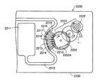
図11は、上述の圧電駆動装置1を利用した送液ポンプ2200の一例を示す説明図である。送液ポンプ2200は、ケース2230内に、リザーバー2211と、チューブ2212と、圧電駆動装置1と、ローター2222と、減速伝達機構2223と、カム2202と、複数のフィンガー2213、2214、2215、2216、2217、2218、2219と、が設けられている。リザーバー2211は、輸送対象である液体を収容するための収容部である。チューブ2212は、リザーバー2211から送り出される液体を輸送するための管である。圧電駆動装置1は、ローター2222の側面に押し付けた状態で設けられており、圧電駆動装置1がローター2222を回転駆動する。ローター2222の回転力は減速伝達機構2223を介してカム2202に伝達される。フィンガー2213から2219はチューブ2212を閉塞させるための部材である。カム2202が回転すると、カム2202の突起部2202Aによってフィンガー2213から2219が順番に放射方向外側に押される。フィンガー2213から2219は、輸送方向上流側(リザーバー2211側)から順にチューブ2212を閉塞する。これにより、チューブ2212内の液体が順に下流側に輸送される。こうすれば、ごく僅かな量を精度良く送液可能で、しかも小型な送液ポンプ2200を実現することができる。なお、各部材の配置は図示されたものには限られない。また、フィンガーなどの部材を備えず、ローター2222に設けられたボールなどがチューブ2212を閉塞する構成であってもよい。上述のような送液ポンプ2200は、インシュリンなどの薬液を人体に投与する投薬装置などに活用できる。ここで、上述した実施形態の圧電駆動装置1を用いることにより、従来の圧電駆動装置よりも大きな出力を得られて、装置の大きさも小さくできるので、投薬装置を小型化できる。
FIG. 11 is an explanatory view showing an example of a
本発明は本実施形態に限定されず、本発明の要旨の範囲内で種々の変形実施が可能である。 The present invention is not limited to the present embodiment, and various modifications can be made within the scope of the gist of the present invention.
上述した実施形態および変形例は一例であって、これらに限定されるわけではない。例えば、各実施形態および各変形例を適宜組み合わせることも可能である。 The above-described embodiments and modifications are merely examples, and the present invention is not limited to these. For example, it is possible to appropriately combine each embodiment and each modification.
本発明は、実施形態で説明した構成と実質的に同一の構成(例えば、機能、方法および結果が同一の構成、あるいは目的および効果が同一の構成)を含む。また、本発明は、実施形態で説明した構成の本質的でない部分を置き換えた構成を含む。また、本発明は、実施形態で説明した構成と同一の作用効果を奏する構成または同一の目的を達成することができる構成を含む。また、本発明は、実施形態で説明した構成に公知技術を付加した構成を含む。 The present invention includes configurations that are substantially the same as the configurations described in the embodiments (for example, configurations that have the same functions, methods, and results, or configurations that have the same objects and effects). In addition, the invention includes a configuration in which a non-essential part of the configuration described in the embodiment is replaced. In addition, the present invention includes a configuration that achieves the same effect as the configuration described in the embodiment or a configuration that can achieve the same object. In addition, the invention includes a configuration in which a known technique is added to the configuration described in the embodiment.
1,2…圧電駆動装置、11,12…圧電振動子、20…固定板、50…モーター、110…振動板、111…固定部、112…振動体部、113…接続部、114…接触部、120…振動板、121…固定部、122…振動体部、123…接続部、124…接触部、500…被駆動体、1001…基板、1002…第1電極、1003…圧電体、1004…第2電極、2000…ロボットハンド、2003…把持部、2010…アーム、2012…リンク部、2020…関節部、2022…手首回動部、2050…ロボット、2200…送液ポンプ、2202…カム、2202A…突起部、2211…リザーバー、2212…チューブ、2213…フィンガー、2222…ローター、2223…減速伝達機構、2230…ケース、I1,I2,S1,S2,Z1,Z2…電極、R1,R2…抵抗、VS0,VS180…電源
DESCRIPTION OF
Claims (6)
前記第1圧電振動子と前記第2圧電振動子とは、
前記固定板に固定される固定部、圧電素子が設けられている振動体部、および前記固定部と前記振動体部とを接続する接続部を備えている振動板と、
前記振動板に配置され、被駆動体に接触する接触部と、
を備え、
前記振動板の主面に平行かつ互いに直交する2つの方向をX方向およびY方向とし、 前記振動板の主面に垂直な方向をZ方向としたとき、
前記第1圧電振動子と前記第2圧電振動子とには、前記固定部、前記振動体部および前記接触部が、前記X方向に沿って設けられ、
前記第1圧電振動子は、
第1電極と、
第1導電体層、第2導電体層、および第3導電体層を含む第2電極と、
前記第1電極と前記第2電極との間に設けられた第1圧電体と、
を有し、
前記第2圧電振動子は、
第3電極と、
第4導電体層、第5導電体層、および第6導電体層を含む第4電極と、
前記第3電極と前記第4電極との間に設けられた第2圧電体と、
を有し、
前記第1導電体層、前記第2導電体層、前記第3導電体層は、前記Y方向に沿って前記第1導電体層、前記第2導電体層、前記第3導電体層の順に配置され、
前記第4導電体層、前記第5導電体層、前記第6導電体層は、前記Y方向に沿って前記第4導電体層、前記第5導電体層、前記第6導電体層の順に配置され、
前記第2導電体層、前記第3導電体層、および前記第4導電体層には、第1交流電圧が入力され、
前記第1導電体層、前記第5導電体層、および前記第6導電体層には、前記第1交流電圧から位相が180度ずれた第2交流電圧が入力され、
前記第1電極と前記第3電極とには、接地電位が入力される、圧電駆動装置。 A piezoelectric drive device comprising a first piezoelectric vibrator and the second piezoelectric vibrator is fixed to a solid Teiita,
The first piezoelectric vibrator and the second piezoelectric vibrator are:
A vibration plate having a fixed portion fixed to the fixed plate, a vibration body portion provided with a piezoelectric element, and a connection portion connecting the fixed portion and the vibration body portion;
A contact portion disposed on the diaphragm and in contact with the driven body;
Equipped with a,
When two directions parallel to and orthogonal to the main surface of the diaphragm are defined as an X direction and a Y direction, and a direction perpendicular to the main surface of the diaphragm is defined as a Z direction,
The first piezoelectric vibrator and the second piezoelectric vibrator are provided with the fixed portion, the vibrating body portion, and the contact portion along the X direction,
The first piezoelectric vibrator is
A first electrode;
A second electrode including a first conductor layer, a second conductor layer, and a third conductor layer;
A first piezoelectric body provided between the first electrode and the second electrode;
Have
The second piezoelectric vibrator is
A third electrode;
A fourth electrode including a fourth conductor layer, a fifth conductor layer, and a sixth conductor layer;
A second piezoelectric body provided between the third electrode and the fourth electrode;
Have
The first conductor layer, the second conductor layer, and the third conductor layer are arranged in the order of the first conductor layer, the second conductor layer, and the third conductor layer along the Y direction. Arranged,
The fourth conductor layer, the fifth conductor layer, and the sixth conductor layer are arranged in the order of the fourth conductor layer, the fifth conductor layer, and the sixth conductor layer along the Y direction. Arranged,
A first AC voltage is input to the second conductor layer, the third conductor layer, and the fourth conductor layer,
A second AC voltage whose phase is shifted by 180 degrees from the first AC voltage is input to the first conductor layer, the fifth conductor layer, and the sixth conductor layer.
A piezoelectric driving device in which a ground potential is input to the first electrode and the third electrode .
前記第1圧電振動子と前記第2圧電振動子とは、前記Y方向に並んで配置されている、圧電駆動装置。 The piezoelectric drive device according to claim 1 ,
The previous SL said first piezoelectric vibrator second piezoelectric vibrators are arranged side by side in the Y-direction, the piezoelectric drive device.
前記第1圧電振動子の前記固定部と前記第2圧電振動子の前記固定部とは、一体として構成されている、圧電駆動装置。 The piezoelectric drive device according to claim 2,
The piezoelectric driving device, wherein the fixed portion of the first piezoelectric vibrator and the fixed portion of the second piezoelectric vibrator are configured as a single unit.
前記圧電素子は、前記振動体部の主面上に設けられ、
前記第1圧電振動子と前記第2圧電振動子とは、前記固定板の+Z方向側の面と−Z方向側の面に、互いの前記圧電素子が形成されていない面どうし、または、前記圧電素子が形成されている面どうしが向かい合うように、配置されている、圧電駆動装置。 The piezoelectric drive device according to claim 1,
The piezoelectric element is provided on a main surface of the vibrating body part ,
The previous SL first piezoelectric vibrator and the second piezoelectric vibrator, wherein a + Z direction side surface and the -Z direction side surface of the fixing plate, each other face not another of said piezoelectric elements are formed, or, A piezoelectric driving device arranged such that surfaces on which the piezoelectric elements are formed face each other.
前記被駆動体と、
を備えている、モーター。 A piezoelectric driving device according to any one of claims 1 to 4,
The driven body;
Equipped with a motor.
前記複数のリンク部を接続する関節部と、
前記関節部を前記被駆動体として駆動する、請求項1ないし4のいずれか1項に記載の圧電駆動装置と、
を備えている、ロボット。
A plurality of link parts;
A joint part connecting the plurality of link parts;
The piezoelectric drive device according to claim 1, wherein the joint portion is driven as the driven body.
Equipped with a robot.
Priority Applications (2)
| Application Number | Priority Date | Filing Date | Title |
|---|---|---|---|
| JP2015133550A JP6617450B2 (en) | 2015-07-02 | 2015-07-02 | Piezoelectric drive, motor and robot |
| US15/194,943 US10256749B2 (en) | 2015-07-02 | 2016-06-28 | Piezoelectric actuator, motor, robot, and method of driving piezoelectric actuator |
Applications Claiming Priority (1)
| Application Number | Priority Date | Filing Date | Title |
|---|---|---|---|
| JP2015133550A JP6617450B2 (en) | 2015-07-02 | 2015-07-02 | Piezoelectric drive, motor and robot |
Publications (3)
| Publication Number | Publication Date |
|---|---|
| JP2017017895A JP2017017895A (en) | 2017-01-19 |
| JP2017017895A5 JP2017017895A5 (en) | 2018-08-02 |
| JP6617450B2 true JP6617450B2 (en) | 2019-12-11 |
Family
ID=57831242
Family Applications (1)
| Application Number | Title | Priority Date | Filing Date |
|---|---|---|---|
| JP2015133550A Active JP6617450B2 (en) | 2015-07-02 | 2015-07-02 | Piezoelectric drive, motor and robot |
Country Status (1)
| Country | Link |
|---|---|
| JP (1) | JP6617450B2 (en) |
Family Cites Families (9)
| Publication number | Priority date | Publication date | Assignee | Title |
|---|---|---|---|---|
| JPS60148384A (en) * | 1984-01-10 | 1985-08-05 | Kanto Jidosha Kogyo Kk | Vibration wave motor |
| JP3334450B2 (en) * | 1995-10-12 | 2002-10-15 | 松下電器産業株式会社 | Piezoelectric actuator and pyroelectric infrared sensor using the same |
| JPH09135585A (en) * | 1995-11-08 | 1997-05-20 | Nikon Corp | Vibrating actuator |
| SE0002885D0 (en) * | 2000-08-11 | 2000-08-11 | Piezomotor Uppsala Ab | Fine walking actuator |
| US7355325B2 (en) * | 2006-06-15 | 2008-04-08 | Piezomotor Uppsala Ab | Wide frequency range electromechanical actuator |
| DE112010006073T5 (en) * | 2010-12-20 | 2013-10-10 | Piezomotor Uppsala Ab | Electromechanical motor |
| DE102011087801B4 (en) * | 2011-02-22 | 2013-04-25 | Physik Instrumente (Pi) Gmbh & Co. Kg | ultrasonic motor |
| JP2013240172A (en) * | 2012-05-14 | 2013-11-28 | Seiko Epson Corp | Piezoelectric motor, robot hand, robot, electronic component transport device, electronic component inspection device, liquid-sending pump, printer, electronic watch, projector, transport device |
| DE102013107154B4 (en) * | 2013-07-08 | 2020-09-10 | Physik Instrumente (Pi) Gmbh & Co. Kg | Drive device |
-
2015
- 2015-07-02 JP JP2015133550A patent/JP6617450B2/en active Active
Also Published As
| Publication number | Publication date |
|---|---|
| JP2017017895A (en) | 2017-01-19 |
Similar Documents
| Publication | Publication Date | Title |
|---|---|---|
| JP6405785B2 (en) | Piezoelectric drive device, robot, and drive method thereof | |
| JP2017017916A (en) | Piezoelectric driving device, robot, and driving method of piezoelectric driving device | |
| US10179405B2 (en) | Piezoelectric drive device, robot, and drive method thereof | |
| JP6439466B2 (en) | Piezoelectric driving device, robot, and robot driving method | |
| JP2016182016A (en) | Piezoelectric drive device and drive method therefor, robot and drive method therefor | |
| JP2017175696A (en) | Control circuit of piezoelectric drive device, piezoelectric drive device, ultrasonic motor, robot, hand, and pump | |
| JP6766328B2 (en) | Piezoelectric drive, robots, and methods of driving piezoelectric drives | |
| JP6442913B2 (en) | Piezoelectric drive device, robot, and drive method thereof | |
| JP2016143755A (en) | Piezoelectric element drive circuit and robot | |
| US10256749B2 (en) | Piezoelectric actuator, motor, robot, and method of driving piezoelectric actuator | |
| JP2016040990A (en) | Piezoelectric drive device, robot, and drive method therefor | |
| JP6601174B2 (en) | Piezoelectric actuators, stacked actuators, piezoelectric motors, robots, hands and liquid pumps | |
| JP2016082835A (en) | Piezoelectric drive device, finger assist device and robot | |
| JP6617450B2 (en) | Piezoelectric drive, motor and robot | |
| JP2016040989A (en) | Piezoelectric drive device and drive method of the same, robot and drive method of the robot | |
| JP6662007B2 (en) | Piezo drives, motors, robots, and pumps | |
| JP6617449B2 (en) | Piezoelectric drive device, motor, robot, and drive method of piezoelectric drive device | |
| JP6702482B2 (en) | Piezoelectric driving device and driving method thereof, robot and driving method thereof | |
| JP2017103956A (en) | Piezoelectric driving device, motor, robot, and pump | |
| JP2017005925A (en) | Piezoelectric driving device for motor, motor, robot and pump | |
| JP2017135935A (en) | Piezoelectric actuator, piezoelectric motor, robot, hand and feed pump | |
| JP6432369B2 (en) | Piezoelectric driving device, robot, and robot driving method | |
| JP2017169416A (en) | Ultrasonic motor, robot, hand, and pump | |
| JP2017103954A (en) | Piezoelectric driving device, motor, robot, and pump | |
| JP6554845B2 (en) | Piezoelectric driving device, robot and driving method thereof |
Legal Events
| Date | Code | Title | Description |
|---|---|---|---|
| A521 | Written amendment |
Free format text: JAPANESE INTERMEDIATE CODE: A523 Effective date: 20180625 |
|
| A621 | Written request for application examination |
Free format text: JAPANESE INTERMEDIATE CODE: A621 Effective date: 20180625 |
|
| A977 | Report on retrieval |
Free format text: JAPANESE INTERMEDIATE CODE: A971007 Effective date: 20190320 |
|
| A131 | Notification of reasons for refusal |
Free format text: JAPANESE INTERMEDIATE CODE: A131 Effective date: 20190403 |
|
| A521 | Written amendment |
Free format text: JAPANESE INTERMEDIATE CODE: A523 Effective date: 20190529 |
|
| TRDD | Decision of grant or rejection written | ||
| A01 | Written decision to grant a patent or to grant a registration (utility model) |
Free format text: JAPANESE INTERMEDIATE CODE: A01 Effective date: 20191015 |
|
| A61 | First payment of annual fees (during grant procedure) |
Free format text: JAPANESE INTERMEDIATE CODE: A61 Effective date: 20191028 |
|
| R150 | Certificate of patent or registration of utility model |
Ref document number: 6617450 Country of ref document: JP Free format text: JAPANESE INTERMEDIATE CODE: R150 |