JP2017103956A - Piezoelectric driving device, motor, robot, and pump - Google Patents
Piezoelectric driving device, motor, robot, and pump Download PDFInfo
- Publication number
- JP2017103956A JP2017103956A JP2015236651A JP2015236651A JP2017103956A JP 2017103956 A JP2017103956 A JP 2017103956A JP 2015236651 A JP2015236651 A JP 2015236651A JP 2015236651 A JP2015236651 A JP 2015236651A JP 2017103956 A JP2017103956 A JP 2017103956A
- Authority
- JP
- Japan
- Prior art keywords
- piezoelectric
- vibrating body
- driving device
- contact portion
- drive device
- Prior art date
- Legal status (The legal status is an assumption and is not a legal conclusion. Google has not performed a legal analysis and makes no representation as to the accuracy of the status listed.)
- Withdrawn
Links
Images


Abstract
Description
本発明は、圧電駆動装置、モーター、ロボット、およびポンプに関する。 The present invention relates to a piezoelectric drive device, a motor, a robot, and a pump.
圧電素子により振動体を振動させて被駆動体を駆動する圧電アクチュエーター(圧電駆動装置)は、磁石やコイルが不要のため、様々な分野で利用されている。 Piezoelectric actuators (piezoelectric driving devices) that drive a driven body by vibrating a vibrating body by a piezoelectric element are used in various fields because they do not require a magnet or a coil.
このような圧電駆動装置において、過渡的な振動の防止、超音波振動子と被駆動体部材との点接触の防止、および電力効率の向上などを目的として、圧電駆動装置の被駆動体との接触部近傍にバネ領域を設けることが記載されている(例えば特許文献1〜3参照)。 In such a piezoelectric driving device, for the purpose of preventing transient vibration, preventing point contact between the ultrasonic vibrator and the driven member, and improving power efficiency, the piezoelectric driving device is connected to the driven member of the piezoelectric driving device. It is described that a spring region is provided in the vicinity of the contact portion (see, for example, Patent Documents 1 to 3).
しかしながら、特許文献1〜3には、バネ領域があるという定性的なことしか記載されておらず、具体的なバネ領域のバネ定数や押圧による変形量などについては、言及されていない。 However, Patent Documents 1 to 3 describe only the qualitative fact that there is a spring region, and do not mention a specific spring constant of the spring region, a deformation amount due to pressing, or the like.
本発明のいくつかの態様に係る目的の1つは、接触部のバネ定数を特定することにより、接触部の磨耗を抑制することができる圧電駆動装置を提供することにある。また、本発明のいくつかの態様に係る目的の1つは、上記の圧電駆動装置を含むモーター、ロボット、またはポンプを提供することにある。 One of the objects according to some aspects of the present invention is to provide a piezoelectric drive device that can suppress wear of a contact portion by specifying a spring constant of the contact portion. Another object of some embodiments of the present invention is to provide a motor, a robot, or a pump including the piezoelectric driving device described above.
本発明は上述の課題の少なくとも一部を解決するためになされたものであり、以下の態様又は適用例として実現することができる。 SUMMARY An advantage of some aspects of the invention is to solve at least a part of the problems described above, and the invention can be implemented as the following aspects or application examples.
[適用例1]
本発明に係る圧電駆動装置の一態様は、
固定部、および圧電素子が設けられ前記固定部に支持された振動体部を有する基板と、
被駆動体に接触し、前記振動体部の動きを前記被駆動体に伝える接触部と、
を含み、
前記接触部は、前記振動体部の屈曲方向と直交する方向における端部に設けられ、
前記接触部の前記屈曲方向におけるバネ定数をKTとし、前記接触部の前記屈曲方向における最大変位量をXTmaxとし、前記接触部と前記被駆動体との間の静止摩擦力をFSとすると、
KT×XTmax<FS
の関係を満たす。
[Application Example 1]
One aspect of the piezoelectric drive device according to the present invention is:
A fixed portion, and a substrate having a vibrating body portion provided with a piezoelectric element and supported by the fixed portion;
A contact portion that contacts the driven body and transmits the movement of the vibrating body portion to the driven body;
Including
The contact portion is provided at an end portion in a direction orthogonal to the bending direction of the vibrating body portion,
The spring constant in the bending direction of the contact portion and K T, the maximum displacement amount in the bent direction of the contact portion and X Tmax, the static frictional force between the driven member and the contact portion and the F S Then
K T × X Tmax <F S
Satisfy the relationship.
このような圧電駆動装置では、接触部は、滑ることなく被駆動体と接触することができる。これにより、このような圧電駆動装置では、接触部の磨耗を抑制することができる。 In such a piezoelectric drive device, the contact portion can contact the driven body without slipping. Thereby, in such a piezoelectric drive device, wear of the contact portion can be suppressed.
[適用例2]
適用例1において、
前記接触部は、先端部と、前記先端部と前記振動体部との間に設けられた接着剤部と、を有し、
前記振動体部は、前記先端部側に突出し前記先端部に接する突出部を有していてもよい。
[Application Example 2]
In application example 1,
The contact portion includes a tip portion, and an adhesive portion provided between the tip portion and the vibrating body portion,
The vibrating body portion may have a protruding portion that protrudes toward the tip portion and contacts the tip portion.
このような圧電駆動装置では、接触部の屈曲方向のバネ定数と、接触部の屈曲方向と直交する方向のバネ定数と、を独立して調整することができる。 In such a piezoelectric drive device, the spring constant in the bending direction of the contact portion and the spring constant in the direction orthogonal to the bending direction of the contact portion can be adjusted independently.
[適用例3]
適用例1において、
前記接触部は、先端部と、前記先端部と前記振動体部との間に設けられた接着剤部と、を有し、
前記先端部は、前記振動体部側に突出し前記振動体部に接する突出部を有していてもよい。
[Application Example 3]
In application example 1,
The contact portion includes a tip portion, and an adhesive portion provided between the tip portion and the vibrating body portion,
The tip portion may have a protruding portion that protrudes toward the vibrating body portion and contacts the vibrating body portion.
このような圧電駆動装置では、接触部の屈曲方向のバネ定数と、接触部の屈曲方向と直交する方向のバネ定数と、を独立して調整することができる。 In such a piezoelectric drive device, the spring constant in the bending direction of the contact portion and the spring constant in the direction orthogonal to the bending direction of the contact portion can be adjusted independently.
[適用例4]
本発明に係るモーターの一態様は、
適用例1ないし3のいずれか1例に記載の圧電駆動装置と、
前記圧電駆動装置によって回転されるローターと、
を含む。
[Application Example 4]
One aspect of the motor according to the present invention is:
The piezoelectric drive device according to any one of Application Examples 1 to 3,
A rotor rotated by the piezoelectric drive device;
including.
このようなモーターでは、本発明に係る圧電駆動装置を含むことができる。 Such a motor can include a piezoelectric drive according to the present invention.
[適用例5]
本発明に係るロボットの一態様は、
複数のリンク部と、
複数の前記リンク部を接続する関節部と、
複数の前記リンク部を前記関節部で回動させる適用例1ないし3のいずれか1例に記載の圧電駆動装置と、
を含む。
[Application Example 5]
One aspect of the robot according to the present invention is:
A plurality of link parts;
A joint part connecting a plurality of the link parts;
The piezoelectric drive device according to any one of Application Examples 1 to 3, in which a plurality of the link portions are rotated at the joint portions,
including.
このようなロボットでは、本発明に係る圧電駆動装置を含むことができる。 Such a robot can include the piezoelectric driving device according to the present invention.
[適用例6]
本発明に係るポンプの一態様は、
適用例1ないし3のいずれか1例に記載の圧電駆動装置と、
液体を輸送するチューブと、
前記圧電駆動装置の駆動によって前記チューブを閉鎖する複数のフィンガーと、
を含む。
[Application Example 6]
One aspect of the pump according to the present invention is:
The piezoelectric drive device according to any one of Application Examples 1 to 3,
A tube that transports the liquid;
A plurality of fingers for closing the tube by driving the piezoelectric driving device;
including.
このようなポンプでは、本発明に係る圧電駆動装置を含むことができる。 Such a pump can include a piezoelectric drive according to the present invention.
以下、本発明の好適な実施形態について、図面を用いて詳細に説明する。なお、以下に説明する実施形態は、特許請求の範囲に記載された本発明の内容を不当に限定するものではない。また、以下で説明される構成の全てが本発明の必須構成要件であるとは限らない。 DESCRIPTION OF EMBODIMENTS Hereinafter, preferred embodiments of the present invention will be described in detail with reference to the drawings. The embodiments described below do not unduly limit the contents of the present invention described in the claims. In addition, not all of the configurations described below are essential constituent requirements of the present invention.
1. 圧電駆動装置
まず、本実施形態に係る圧電駆動装置について、図面を参照しながら説明する。図1は、本実施形態に係る圧電駆動装置100を模式的に示す平面図である。図2は、本実施形態に係る圧電駆動装置100を模式的に示す図1のII−II線断面である。図3は、本実施形態に係る圧電駆動装置100の接触部20近傍を模式的に示す斜視図である。
1. Piezoelectric Drive Device First, a piezoelectric drive device according to the present embodiment will be described with reference to the drawings. FIG. 1 is a plan view schematically showing a
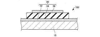
圧電駆動装置100は、図1〜図3に示すように、基板10と、接触部20と、圧電素子30と、を含む。
As shown in FIGS. 1 to 3, the
基板10は、例えば、シリコン基板と、シリコン基板上に設けられた酸化シリコン層と、酸化シリコン層上に設けられた酸化ジルコニウム層と、の積層体から構成されている。
The
基板10は、図1に示すように、振動体部12と、固定部14と、第1接続部16と、第2接続部18と、を有している。図示の例では、振動体部12の平面形状(基板10の厚さ方向からみた形状)は、略長方形である。振動体部12上には、圧電素子30が設けられ、振動体部12は、圧電素子30の変形により振動することができる。固定部14は、接続部16,18を介して、振動体部12を支持している。固定部14は、例えば、外部部材(図示せず)に固定されている。図示の例では、接続部16,18は、振動体部12の長手方向における中央部から、該長手方向と直交する方向に延出し、固定部14に接続されている。
As shown in FIG. 1, the
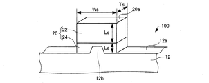
接触部20は、振動体部12の長手方向(以下、単に「長手方向」ともいう)における端部12aに設けられている。長手方向は、振動体部12の屈曲方向と直交する方向である。図3に示す例では、振動体部12は、端部12aに、接触部20の先端部22側に突出する突出部12bを有している。接触部20は、例えば、突出部12bに嵌合して設けられている。図示の例では、突出部12bは、先端部22と離間している。なお、便宜上、図1および後述する図5では、突出部12bの図示を省略している。
The
接触部20は、先端20aを有し、接触部20は、先端20aにおいて被駆動部材(後述する図5に示すローター4)と接触して、振動体部12の動きを被駆動部材に伝える部材である。ローター4の形状は、例えば、円柱状、球状である。
The
接触部20は、先端20aを構成する先端部22と、先端部22と振動体部12との間に設けられた接着剤部24と、を有している。先端部22の材質は、例えば、セラミックス(具体的にはアルミナ(Al2O3)、ジルコニア(ZrO2)、窒化ケイ素(Si3N)、またはこれらの混合物など)である。図示の例では、先端部22の形状は、直方体である。接着剤部24は、先端部22と振動体部12とを接着させる接着剤によって構成されている。
The
図3に示す例では、接触部20の先端部22および接着剤部24の長手方向と直交する幅方向の長さをWs、先端部22および接着剤部24の長手方向および幅方向と直交する方向の長さをTs、先端部22の長手方向の長さをLs、接着剤部24の長手方向の長さをLaとしている。
In the example shown in FIG. 3, the length in the width direction perpendicular to the longitudinal direction of the
長さWsは、例えば、0.1mm以上0.5mm以下である。長さTsは、例えば、0.1mm以上0.5mm以下である。長さLsは、例えば、0.1mm以上0.5mm以下である。長さLaは、例えば、0.5μm以上15μm以下である。より具体的には、Ws=0.2mm、Ts=0.2mmm、Ls=0.1mm、La=3μmである。 The length Ws is, for example, not less than 0.1 mm and not more than 0.5 mm. The length Ts is, for example, not less than 0.1 mm and not more than 0.5 mm. The length Ls is, for example, not less than 0.1 mm and not more than 0.5 mm. The length La is, for example, not less than 0.5 μm and not more than 15 μm. More specifically, Ws = 0.2 mm, Ts = 0.2 mm, Ls = 0.1 mm, and La = 3 μm.
圧電素子30は、図2に示すように、基板10上に設けられている。具体的には、圧電素子30は、振動体部12上に設けられている。圧電素子30は、第1電極32と、圧電体層34と、第2電極36と、を有している。
The
第1電極32は、振動体部12上に設けられている。図1に示す例では、第1電極32の平面形状は、長方形である。第1電極32は、振動体部12上に設けられたイリジウム層と、イリジウム層上に設けられた白金層と、によって構成されていてもよい。イリジウム層の厚さは、例えば、5nm以上100nm以下である。白金層の厚さは、例えば、50nm以上300nm以下である。なお、第1電極32は、Ti、Pt、Ta、Ir、Sr、In、Sn、Au、Al、Fe、Cr、Ni、Cuなどからなる金属層、またはこれらの2種以上を混合または積層したものであってもよい。第1電極32は、圧電体層34に電圧を印加するための一方の電極である。
The
圧電体層34は、第1電極32上に設けられている。図示の例では、圧電体層34の平面形状は、長方形である。圧電体層34の厚さは、例えば、50nm以上20μm以下であり、好ましくは、1μm以上7μm以下である。このように、圧電素子30は、薄膜圧電素子である。圧電体層34の厚さが50nmより小さいと、圧電駆動装置100の出力が小さくなる場合がある。具体的には、出力を上げようとして圧電体層34への印加電圧を高くすると、圧電体層34が絶縁破壊を起こす場合がある。圧電体層34の厚さが20μmより大きいと、圧電体層34にクラックが生じる場合がある。
The
圧電体層34としては、ペロブスカイト型酸化物の圧電材料を用いる。具体的には、圧電体層34の材質は、例えば、チタン酸ジルコン酸鉛(Pb(Zr,Ti)O3:PZT)、ニオブ酸チタン酸ジルコン酸鉛(Pb(Zr,Ti,Nb)O3:PZTN)である。圧電体層34は、電極32,36によって電圧が印加されることにより、変形(伸縮)することができる。
As the
第2電極36は、圧電体層34上に設けられている。図示の例では、第2電極36の平面形状は、長方形である。第2電極36は、圧電体層34上に設けられた密着層と、密着層上に設けられた導電層と、によって構成されていてもよい。密着層の厚さは、例えば、10nm以上100nm以下である。密着層は、例えば、TiW層、Ti層、Cr層、NiCr層や、これらの積層体である。導電層の厚さは、例えば、1μm以上10μm以下
である。導電層は、例えば、Cu層、Au層、Al層やこれらの積層体である。第2電極36は、圧電体層34に電圧を印加するための他方の電極である。
The
圧電素子30は、複数設けられている。図1に示す例では、圧電素子30は、5つ設けられている(圧電素子30a,30b,30c,30d,30e)。平面視において(基板10の厚さ方向からみて)、例えば、圧電素子30a〜30dの面積は同じであり、圧電素子30eは、圧電素子30a〜30dよりも大きな面積を有している。圧電素子30eは、振動体部12の短手方向の中央部において、振動体部12の長手方向に沿って設けられている。圧電素子30a,30b,30c,30dは、振動体部12の四隅に設けられている。図示の例では、圧電素子30a〜30eにおいて、第1電極32は、1つの連続的な導電層として設けられている。
A plurality of
なお、図示はしないが、圧電駆動装置100は、圧電素子30を覆うように設けられた絶縁層や、第1電極32と電気的に接続された第1配線層、および第2電極36と電気的に接続された第2配線層を有していてもよい。
Although not shown, the
図4は、圧電駆動装置100を説明するための等価回路を示す図である。圧電素子30は、3つのグループに分けられる。第1グループは、2つの圧電素子30a,30dを有する。第2グループは、2つの圧電素子30b,30cを有する。第3グループは、1つの圧電素子30eのみを有する。図4に示すように、第1グループの圧電素子30a,30dは、互いに並列に接続され、駆動回路110に接続されている。第2グループの圧電素子30b,30cは、互いに並列に接続され、駆動回路110に接続されている。第3グループの圧電素子30eは、単独で駆動回路110に接続されている。
FIG. 4 is a diagram showing an equivalent circuit for explaining the
駆動回路110は、5つの圧電素子30a,30b,30c,30d,30eのうちの所定の圧電素子、例えば、圧電素子30a,30d,30eの第1電極32と第2電極36との間に周期的に変化する交流電圧または脈流電圧を印加する。これにより、圧電駆動装置100は、振動体部12を超音波振動させて、接触部20に接触するローター(被駆動部材)を所定の回転方向に回転させることができる。ここで、「脈流電圧」とは、交流電圧にDCオフセットを付加した電圧を意味し、脈流電圧の電圧(電界)の向きは、一方の電極から他方の電極に向かう一方向である。
The
なお、電界の向きは、第1電極32から第2電極36に向かうよりも第2電極36から第1電極32に向かう方が好ましい。また、圧電素子30b,30c,30eの電極32,36間に交流電圧または脈流電圧を印加することにより、接触部20に接触するローターを逆方向に回転させることができる。
The direction of the electric field is preferably from the
図5は、圧電駆動装置100の振動体部12の動作を説明するための図である。圧電駆動装置100の接触部20は、図5に示すように、被駆動部材としてのローター4の外周に接触している。駆動回路110は、圧電素子30a,30dの電極32,36間に交流電圧または脈流電圧を印加する。これにより、圧電素子30a,30dは、矢印xの方向に伸縮する。これに応じて、振動体部12は、振動体部12の平面内で屈曲振動して蛇行形状(S字形状)に変形する。さらに、駆動回路110は、圧電素子30eの電極32,36間に交流電圧または脈流電圧を印加する。これにより、圧電素子30eは、矢印yの方向に伸縮する。これにより、振動体部12は、振動体部12の平面内で縦振動する。上記のような振動体部12の屈曲振動および縦振動によって、振動体部12の接触部20との境界部(接続部)は、矢印zのように楕円運動する。その結果、ローター4は、その中心4aの周りに所定の方向R(図示の例では時計回り方向)に回転する。
FIG. 5 is a diagram for explaining the operation of the vibrating
なお、駆動回路110が、圧電素子30b,30c,30eの電極32,36間に交流
電圧または脈流電圧を印加する場合には、ローター4は、方向Rとは反対方向(反時計回り方向)に回転する。
When the
また、振動体部12の屈曲振動の共振周波数と縦振動の共振周波数とは、同じであることが好ましい。これにより、圧電駆動装置100は、効率よくローター4を回転させることができる。
Moreover, it is preferable that the resonance frequency of the bending vibration and the resonance frequency of the longitudinal vibration of the vibrating
図5に示すように、本実施形態に係るモーター120は、本発明に係る圧電駆動装置(図示の例では圧電駆動装置100)と、圧電駆動装置100によって回転されるローター4と、を含む。ローター4の材質は、例えば、セラミックスである。図示の例では、ローター4の形状は、円柱状である。
As shown in FIG. 5, the
図6は、圧電駆動装置100の振動体部12の動作を、より詳細に説明するため図である。振動体部12は、図6に示すように、状態(A)から状態(F)まで順に変形し、再び状態(A)に戻る。この動作を、圧電駆動装置100が駆動している間(圧電素子30に電圧が印加されている間)繰り返す。なお、図6において、破線で示した長方形は、圧電駆動装置100が駆動していない状態での振動体部12(具体的には、便宜上、突出部12bが設けられていない振動体部12)を示している。
FIG. 6 is a diagram for explaining the operation of the vibrating
図6では、振動体部12の接触部20との境界部(例えば突出部12b)が描く楕円をzで示している。突出部12bは、時計回りに回転する。ローター4は、反時計回りに回転する。ローター4の回転速度は、ほぼ一定である。ローター4表面の移動速度は、突出部12bの屈曲方向速度の平均(圧電駆動装置100が駆動され、接触部20の先端20aがローター4と接触している間の平均)とほぼ同じである。
In FIG. 6, an ellipse drawn by a boundary portion (for example, the protruding
状態(A)は、振動体部12が縦方向(長手方向)に最も縮んだ状態であり、接触部20とローター4とは、離間している。状態(A)では、突出部12bの第1方向(図6の左側へ向かう方向)への移動速度は、最大(圧電駆動装置100が駆動している間で最大)となる。
State (A) is a state in which the vibrating
状態(B)を経て、状態(C)において、接触部20は、ローター4と接触している。状態(C)では、図示の例では、接触部20の先端20a全面がローター4と接触している。状態(C)では、突出部12bは、第2方向(図6の右側へ向かう方向)へ移動する。しかし、突出部12bの移動速度は、ローター4の回転速度よりも小さいため、接着剤部24が変形して、突出部12bは、先端部22よりも遅れた状態となる。接着剤部24は、例えば、先端部22のヤング率よりも小さいヤング率を有している。
After the state (B), in the state (C), the
状態(D)では、振動体部12が縦方向に最も伸びた状態であり、突出部12bの第2方向への移動速度は、最大となる。そのため、状態(E)では、接着剤部24が変形して、突出部12bは、先端部22よりも進んだ状態となる。状態(E)では、接触部20の先端20a全面がローター4と接触している。
In the state (D), the vibrating
そして、状態(F)では、接触部20は、ローター4と離間し、再び、状態(A)に戻る。
In the state (F), the
ここで、圧電駆動装置100では、接触部20の屈曲方向におけるバネ定数をKTとし、接触部20の屈曲方向における最大変位量をXTmaxとし、接触部20とローター4との間の静止摩擦力をFSとすると、下記式(1)を満たす。
Here, the
KT×XTmax<FS ・・・ (1) K T × X Tmax <F S (1)
そのため、圧電駆動装置100では、状態(C)〜状態(E)において、接触部20は、滑ることなくローター4と接触することができる。状態(C)および状態(E)における先端部22速度とローター4の速度との差は、例えば、接着剤部24が変形する(弾性変形する)ことにより吸収することができる。
Therefore, in the
なお、接触部20の屈曲方向における最大変位量XTmaxとは、振動体部12が屈曲方向に変形していない状態を基準とした(例えば状態(D))、屈曲方向(第1方向、第2方向)における突出部12bの変位量である。具体的には、最大変位量XTmaxは、突出部12bが描く楕円zの屈曲方向成長さの半分である。図示の例では、最大変位量XTmaxは、長軸の長さの半分と同一である。
The maximum displacement amount XTmax in the bending direction of the
圧電駆動装置100は、例えば、以下の特徴を有する。
The
圧電駆動装置100では、式(1)を満たす。そのため、接触部20は、滑ることなくローター4と接触することができる。これにより、圧電駆動装置100では、接触部20の磨耗を抑制することができる。その結果、圧電駆動装置100では、接触部20の長寿命化を図ることができる。例えば接触部が大きい場合は、接触部が少々磨耗しても圧電駆動装置の特性に大きな変化はないが、本実施形態に係る圧電駆動装置100の接触部20は、例えば、Ws=0.2mm、Ts=0.2mmm、Ls=0.1mm、La=3μmと小型であり、接触部20が少し磨耗するだけで圧電駆動装置100の特性が変化してしまう場合がある。したがって、小型な接触部20では、磨耗の抑制が重要となる。
The
さらに、圧電駆動装置100では、接触部20がローター4に対して滑らないので、振動体部12の変形による復元力を低減させることなく、効率よく該復元力をローター4に伝えることができる。さらに、圧電駆動装置100では、接触部20のローター4との接触する部分が、状態(C)〜状態(E)において、ローター4に対して変位しないので、ローター4の回転速度やトルクの変動を小さくすることができ、安定して駆動することができる。
Further, in the
圧電駆動装置100では、例えば、突出部12bが描く楕円zの上半分側(ローター4側の半分側)において、接触部20をローター4に接させ、楕円zの下半分側(ローター4とは反対側の半分側)において、接触部20をローターと離間させることができる。これにより、圧電駆動装置100は、振動体部12の変形による復元力を、効率よくローター4に伝えることができる。
In the
2. 圧電駆動装置の製造方法
次に、本実施形態に係る圧電駆動装置の製造方法について、図面を参照しながら説明する。
2. Next, a method for manufacturing a piezoelectric drive device according to the present embodiment will be described with reference to the drawings.
図1および図2に示すように、基板10の振動体部12上に第1電極32を形成する。第1電極32は、例えば、スパッタ法、CVD(Chemical Vapor Deposition)法、真空蒸着法などによる成膜、およびパターニング(フォトリソグラフィーおよびエッチングによるパターニング)により形成される。
As shown in FIGS. 1 and 2, the
次に、第1電極32上に圧電体層34を形成する。圧電体層34、例えば、液相法による前駆体層の形成と該前駆体層の結晶化とを繰り返した後、パターニングすることによって形成される。液相法とは、薄膜(圧電体層)の構成材料を含む原料液を用いて薄膜材料を成膜する方法であり、具体的には、ゾルゲル法やMOD(Metal Organic
Deposition)法などである。結晶化は、酸素雰囲気において、例えば、70
0℃〜800℃の熱処理により行われる。
Next, the
Deposition) method and the like. Crystallization is performed in an oxygen atmosphere, for example, 70
The heat treatment is performed at 0 ° C to 800 ° C.
次に、圧電体層34に第2電極36を形成する。第2電極36は、例えば、第1電極32と同じ方法で形成される。なお、図示はしないが、第2電極36のパターニングと圧電体層34のパターニングとは、同一の工程として行われてもよい。
Next, the
以上の工程により、基板10の振動体部12上に、圧電素子30を形成することができる。
Through the above steps, the
次に、接着剤部24を介して、先端部22を振動体部12の端部12aに接着させる。これにより、端部12aに接触部20を設けることができる。
Next, the
以上の工程により、圧電駆動装置100を製造することができる。
The
3. 圧電駆動装置の変形例
3.1. 第1変形例
次に、本実施形態の第1変形例に係る圧電駆動装置について、図面を参照しながら説明する。図7は、本実施形態の第1変形例に係る圧電駆動装置200を模式的に示す平面図である。
3. Modified example of piezoelectric drive device 3.1. First Modification Next, a piezoelectric drive device according to a first modification of the present embodiment will be described with reference to the drawings. FIG. 7 is a plan view schematically showing a
以下、本実施形態の第1変形例に係る圧電駆動装置200において、本実施形態に係る圧電駆動装置100の構成部材と同様の機能を有する部材については同一の符号を付し、その詳細な説明を省略する。このことは、以下に示す本実施形態の第2変形例に係る圧電駆動装置においても同様である。
Hereinafter, in the
上述した圧電駆動装置100では、図3に示すように、振動体部12の端部12aには、突出部12bが設けられていた。これに対し、圧電駆動装置200では、図7に示すように、端部12aには、突出部12bは設けられていない。
In the
圧電駆動装置200では、圧電駆動装置100と同様に、接触部20の磨耗を抑制することができる。
In the
なお、図7に示す例では、先端部22の形状は直方体であるが、先端部22の形状は、図8に示すように半球状であってもよく、図9に示すように球状であってもよい。図9に示す例では、振動体部12の端部12aに切り欠き13が設けられ、切り欠き13に接着剤部24が充填されている。
In the example shown in FIG. 7, the shape of the
3.2. 第2変形例
次に、本実施形態の第2変形例に係る圧電駆動装置について、図面を参照しながら説明する。図10は、本実施形態の第2変形例に係る圧電駆動装置300を模式的に示す平面図である。
3.2. Second Modified Example Next, a piezoelectric driving device according to a second modified example of the present embodiment will be described with reference to the drawings. FIG. 10 is a plan view schematically showing a
上述した圧電駆動装置100では、図3に示すように、振動体部12は、端部12aに突出部12bを有し、突出部12bは、先端部22と離間していた。これに対し、圧電駆動装置300では、図10に示すように、振動体部12は、先端部22側に突出し先端部22に接する突出部12bを有している。突出部12bは、端部12aの短手方向における中央部に設けられている。長手方向および幅方向と直交する方向の長さにおいて、突出部12bと接着剤部24とは、同じ長さである。図10に示す例では、突出部12bの幅方向の長さをWtとしている。長さWtは、例えば、1μm以上50μ以下であり、より具体的には、20μmである。
In the
圧電駆動装置300では、圧電駆動装置100と同様に、接触部20の磨耗を抑制することができる。さらに、圧電駆動装置300では、突出部12bにより、接触部20の長手方向のバネ定数と、接触部20の屈曲方向のバネ定数と、を独立して調整することができる(詳細は後述する「4. 実験例」参照)。
In the
なお、図11に示すように、振動体部12は突出部12bを有しておらず、先端部22は、振動体部12側に突出し振動体部12に接する突出部12bを有していてもよい。
As shown in FIG. 11, the vibrating
4. 実験例
以下に実験例を示し、本発明をより具体的に説明する。なお、本発明は、以下の実験例によって何ら限定されるものではない。
4). Experimental Example An experimental example is shown below to describe the present invention more specifically. The present invention is not limited by the following experimental examples.
4.1. バネ定数に関する計算
接触部とローターとの間の静止摩擦係数をμs、接触部とローターとの間の静止摩擦力をFS、接触部の屈曲方向における最大変位量をXTmax、接触部の先端を縦方向に押し当てた(押圧した)押圧力をFPr、接触部の屈曲方向のバネ定数をKTとした。接触部が最大に変位したときでも、ローターに対して滑らない条件は、下記式(2)となる。したがって、静止摩擦係数μs=0.5、最大変位量XTmax=1μm、押圧力FPr=0.5Nとした場合は、下記式(3)を満たせば、接触部が屈曲方向に最大に変位したときでも、接触部はローターに対して滑らない。
4.1. Calculation concerning spring constant The coefficient of static friction between the contact portion and the rotor is μs, the static friction force between the contact portion and the rotor is F S , the maximum displacement amount in the bending direction of the contact portion is X Tmax , and the tip of the contact portion Was pressed (pressed) in the vertical direction as F Pr , and the spring constant in the bending direction of the contact portion as KT . Even when the contact portion is displaced to the maximum, the condition that does not slip with respect to the rotor is the following equation (2). Therefore, when the static friction coefficient μs = 0.5, the maximum displacement amount X Tmax = 1 μm, and the pressing force F Pr = 0.5N, the contact portion is displaced to the maximum in the bending direction if the following expression (3) is satisfied. Even when this is done, the contact portion does not slip relative to the rotor.
FS=μs×FPr>KT×XTmax ・・・ (2)
KT<(μs×FPr)/XTmax=2.5×105N/m ・・・ (3)
F S = μs × F Pr > K T × X Tmax (2)
K T <(μs × F Pr ) / X Tmax = 2.5 × 10 5 N / m (3)
4.2. バネ定数に関するシミュレーション
4.2.1. 図7に示すようなモデルでのシミュレーション
上述した図7に示すような接触部をモデルとして、接触部の先端に長手方向に1Nを印加したときの接触部の変形量を有限要素法によるシミュレーションで求めた。そして、求めた変形量からバネ定数を算出した。接触部の先端部としては、アルミナを想定した。各寸法およびヤング率は、下記の通りである。
4.2. Simulation on spring constant 4.2.1. Simulation with a model as shown in FIG. 7 Using the contact portion as shown in FIG. 7 as a model, the deformation amount of the contact portion when 1N is applied to the tip of the contact portion in the longitudinal direction is simulated by a finite element method. Asked. Then, the spring constant was calculated from the obtained deformation amount. Alumina was assumed as the tip of the contact portion. Each dimension and Young's modulus are as follows.
先端部のヤング率:3.7×10¹¹N/m2
先端部および接着剤部の長さWs:200μm
先端部および接着剤部の長さTs:200μm
先端部の長さLs:100μm
接着剤部のヤング率:3×10⁷N/m2
接着剤部の長さLa:3μm
Young's modulus at the tip: 3.7 × 10 11 N / m 2
Length Ws of tip part and adhesive part: 200 μm
Length Ts of tip part and adhesive part: 200 μm
Tip length Ls: 100 μm
Young's modulus of the adhesive part: 3 × 10 7 N / m 2
Adhesive length La: 3 μm
下記表1は、シミュレーションで求めた変位量とバネ定数との関係を示している。表1より、上記のような条件では、屈曲方向のバネ定数を、上記の「4.1.」の計算で求めた、2.5×10⁵N/mよりも小さくできることがわかった。 Table 1 below shows the relationship between the amount of displacement determined by simulation and the spring constant. From Table 1, it was found that under the above conditions, the spring constant in the bending direction can be made smaller than 2.5 × 10 5 N / m obtained by the calculation of “4.1.” Above.

4.2.2. 図10に示すようなモデルでのシミュレーション
次に、上述した図10に示すような接触部をモデルとして、上記の「4.2.1.」と同じシミュレーションを行った。下記に示す条件以外は、上記の「4.2.1.」と同じ条件でシミュレーションを行った。振動体部としては、シリコンを想定した。
4.2.2. Simulation with Model as shown in FIG. 10 Next, the same simulation as the above “4.2.1.” Was performed using the contact portion as shown in FIG. A simulation was performed under the same conditions as in the above “4.2.1.” Except for the conditions shown below. As the vibrating part, silicon was assumed.
接着剤部の長さLa:10μm
振動体部の(突起部の)ヤング率:1.59×11N/m2
突起部の長さWt:20μm
Adhesive length La: 10 μm
Young's modulus of the vibrating body (projection): 1.59 × 11 N / m 2
Projection length Wt: 20 μm
下記表2は、シミュレーションで求めた変位量とバネ定数との関係を示している。表2より、屈曲方向のバネ定数を2.5×10⁵N/mよりも小さくしつつ、長手方向のバネ定数を、図7に示したモデルとは異なる値にできることがわかった。すなわち、突起部を設けることにより、接触部の長手方向のバネ定数と屈曲方向のバネ定数とを、独立して調整することができることがわかった。 Table 2 below shows the relationship between the amount of displacement determined by simulation and the spring constant. Table 2 shows that the spring constant in the longitudinal direction can be set to a value different from the model shown in FIG. 7 while the spring constant in the bending direction is made smaller than 2.5 × 10 5 N / m. That is, it has been found that by providing the protrusions, the spring constant in the longitudinal direction and the spring constant in the bending direction of the contact part can be adjusted independently.
5. 圧電駆動装置を用いた装置
本発明に係る圧電駆動装置は、共振を利用することで被駆動体に対して大きな力を与えることができるものであり、各種の装置に適用可能である。本発明に係る圧電駆動装置は、例えば、ロボット(電子部品搬送装置(ICハンドラー)も含む)、投薬用ポンプ、時計のカレンダー送り装置、印刷装置の紙送り機構等の各種の機器における駆動装置として用いることが出来る。以下、代表的な実施の形態について説明する。以下では、本発明に係る圧電駆動装置として、圧電駆動装置100を含む装置について説明する。
5). Device Using Piezoelectric Drive Device The piezoelectric drive device according to the present invention can apply a large force to a driven body by utilizing resonance, and can be applied to various devices. The piezoelectric drive device according to the present invention is, for example, as a drive device in various devices such as a robot (including an electronic component transfer device (IC handler)), a dosing pump, a calendar feeding device for a clock, and a paper feeding mechanism for a printing device. Can be used. Hereinafter, representative embodiments will be described. Hereinafter, an apparatus including the
5.1. ロボット
図12は、圧電駆動装置100を利用したロボット2050を説明するための図である。ロボット2050は、複数本のリンク部2012(「リンク部材」とも呼ぶ)と、それらリンク部2012の間を回動または屈曲可能な状態で接続する複数の関節部2020と、を備えたアーム2010(「腕部」とも呼ぶ)を有している。
5.1. Robot FIG. 12 is a diagram for explaining a
それぞれの関節部2020には、圧電駆動装置100が内蔵されており、圧電駆動装置100を用いて関節部2020を任意の角度だけ回動または屈曲させることが可能である。アーム2010の先端には、ロボットハンド2000が接続されている。ロボットハンド2000は、一対の把持部2003を備えている。ロボットハンド2000にも圧電駆動装置100が内蔵されており、圧電駆動装置100を用いて把持部2003を開閉して物を把持することが可能である。また、ロボットハンド2000とアーム2010との間にも圧電駆動装置100が設けられており、圧電駆動装置100を用いてロボットハンド2000をアーム2010に対して回転させることも可能である。
Each
図13は、図12に示したロボット2050の手首部分を説明するための図である。手首の関節部2020は、手首回動部2022を挟持しており、手首回動部2022に手首のリンク部2012が、手首回動部2022の中心軸O周りに回動可能に取り付けられている。手首回動部2022は、圧電駆動装置100を備えており、圧電駆動装置100は
、手首のリンク部2012およびロボットハンド2000を中心軸O周りに回動させる。ロボットハンド2000には、複数の把持部2003が立設されている。把持部2003の基端部はロボットハンド2000内で移動可能となっており、この把持部2003の根元の部分に圧電駆動装置100が搭載されている。このため、圧電駆動装置100を動作させることで、把持部2003を移動させて対象物を把持することができる。なお、ロボットとしては、単腕のロボットに限らず、腕の数が2以上の多腕ロボットにも圧電駆動装置100を適用可能である。
FIG. 13 is a view for explaining a wrist portion of the
ここで、手首の関節部2020やロボットハンド2000の内部には、圧電駆動装置100の他に、力覚センサーやジャイロセンサー等の各種装置に電力を供給する電力線や、信号を伝達する信号線等が含まれ、非常に多くの配線が必要になる。したがって、関節部2020やロボットハンド2000の内部に配線を配置することは非常に困難だった。しかしながら、圧電駆動装置100は、通常の電動モーターよりも駆動電流を小さくできるので、関節部2020(特に、アーム2010の先端の関節部)やロボットハンド2000のような小さな空間でも配線を配置することが可能になる。
Here, in the wrist joint 2020 and the
5.2. ポンプ
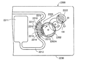
図14は、圧電駆動装置100を利用した送液ポンプ2200の一例を示す説明するための図である。送液ポンプ2200は、ケース2230内に、リザーバー2211と、チューブ2212と、圧電駆動装置100と、ローター2222と、減速伝達機構2223と、カム2202と、複数のフィンガー2213,2214,2215,2216,2217,2218,2219と、を含む。
5.2. Pump FIG. 14 is a diagram for explaining an example of a
リザーバー2211は、輸送対象である液体を収容するための収容部である。チューブ2212は、リザーバー2211から送り出される液体を輸送するための管である。圧電駆動装置100の接触部20は、ローター2222の側面に押し付けた状態で設けられており、圧電駆動装置100がローター2222を回転駆動する。ローター2222の回転力は減速伝達機構2223を介してカム2202に伝達される。フィンガー2213から2219はチューブ2212を閉塞させるための部材である。カム2202が回転すると、カム2202の突起部2202Aによってフィンガー2213から2219が順番に放射方向外側に押される。フィンガー2213から2219は、輸送方向上流側(リザーバー2211側)から順にチューブ2212を閉塞する。これにより、チューブ2212内の液体が順に下流側に輸送される。こうすれば、ごく僅かな量を精度良く送液可能で、しかも小型な送液ポンプ2200を実現することができる。
The
なお、各部材の配置は図示されたものには限られない。また、フィンガーなどの部材を備えず、ローター2222に設けられたボールなどがチューブ2212を閉塞する構成であってもよい。上記のような送液ポンプ2200は、インシュリンなどの薬液を人体に投与する投薬装置などに活用できる。ここで、圧電駆動装置100を用いることにより、通常の電動モーターよりも駆動電流を小さくできるので、投薬装置の消費電力を抑制することができる。したがって、投薬装置を電池駆動する場合は、特に有効である。
In addition, arrangement | positioning of each member is not restricted to what was illustrated. Further, a member such as a finger may not be provided, and a ball or the like provided on the
本発明は、本願に記載の特徴や効果を有する範囲で一部の構成を省略したり、各実施形態や変形例を組み合わせたりしてもよい。 In the present invention, a part of the configuration may be omitted within a range having the characteristics and effects described in the present application, or each embodiment or modification may be combined.
本発明は、実施の形態で説明した構成と実質的に同一の構成(例えば、機能、方法及び結果が同一の構成、あるいは目的及び効果が同一の構成)を含む。また、本発明は、実施の形態で説明した構成の本質的でない部分を置き換えた構成を含む。また、本発明は、実施の形態で説明した構成と同一の作用効果を奏する構成又は同一の目的を達成することができる構成を含む。また、本発明は、実施の形態で説明した構成に公知技術を付加した構
成を含む。
The present invention includes configurations that are substantially the same as the configurations described in the embodiments (for example, configurations that have the same functions, methods, and results, or configurations that have the same objects and effects). In addition, the invention includes a configuration in which a non-essential part of the configuration described in the embodiment is replaced. In addition, the present invention includes a configuration that exhibits the same operational effects as the configuration described in the embodiment or a configuration that can achieve the same object. Further, the invention includes a configuration in which a known technique is added to the configuration described in the embodiment.
4…ローター、4a…中心、10…基板、12…振動体部、12a…端部、12b…突出部、13…切り欠き、14…固定部、16…第1接続部、18…第2接続部、20…接触部、20a…先端、22…先端部、24…接着剤部、30,30a,30b,30c,30d,30e…圧電素子、32…第1電極、34…圧電体層、36…第2電極、100…圧電駆動装置、110…駆動回路、120…モーター、200,300…圧電駆動装置、2000…ロボットハンド、2003…把持部、2010…アーム、2012…リンク部、2020…関節部、2050…ロボット、2200…送液ポンプ、2202…カム、2202A…突起部、2211…リザーバー、2212…チューブ、2213,2214,2215,2216,2217,2218,2219…フィンガー、2222…ローター、2223…減速伝達機構、2230…ケース
DESCRIPTION OF
Claims (6)
被駆動体に接触し、前記振動体部の動きを前記被駆動体に伝える接触部と、
を含み、
前記接触部は、前記振動体部の屈曲方向と直交する方向における端部に設けられ、
前記接触部の前記屈曲方向におけるバネ定数をKTとし、前記接触部の前記屈曲方向における最大変位量をXTmaxとし、前記接触部と前記被駆動体との間の静止摩擦力をFSとすると、
KT×XTmax<FS
の関係を満たす、圧電駆動装置。 A fixed portion, and a substrate having a vibrating body portion provided with a piezoelectric element and supported by the fixed portion;
A contact portion that contacts the driven body and transmits the movement of the vibrating body portion to the driven body;
Including
The contact portion is provided at an end portion in a direction orthogonal to the bending direction of the vibrating body portion,
The spring constant in the bending direction of the contact portion and K T, the maximum displacement amount in the bent direction of the contact portion and X Tmax, the static frictional force between the driven member and the contact portion and the F S Then
K T × X Tmax <F S
Piezoelectric drive device that satisfies the above relationship.
前記接触部は、先端部と、前記先端部と前記振動体部との間に設けられた接着剤部と、を有し、
前記振動体部は、前記先端部側に突出し前記先端部に接する突出部を有している、圧電駆動装置。 In claim 1,
The contact portion includes a tip portion, and an adhesive portion provided between the tip portion and the vibrating body portion,
The piezoelectric drive device, wherein the vibrating body portion has a protruding portion that protrudes toward the distal end side and contacts the distal end portion.
前記接触部は、先端部と、前記先端部と前記振動体部との間に設けられた接着剤部と、を有し、
前記先端部は、前記振動体部側に突出し前記振動体部に接する突出部を有している、圧電駆動装置。 In claim 1,
The contact portion includes a tip portion, and an adhesive portion provided between the tip portion and the vibrating body portion,
The piezoelectric drive device, wherein the tip portion has a protruding portion that protrudes toward the vibrating body portion and contacts the vibrating body portion.
前記圧電駆動装置によって回転されるローターと、
を含む、モーター。 A piezoelectric driving device according to any one of claims 1 to 3,
A rotor rotated by the piezoelectric drive device;
Including a motor.
複数の前記リンク部を接続する関節部と、
複数の前記リンク部を前記関節部で回動させる請求項1ないし3のいずれか1項に記載の圧電駆動装置と、
を含む、ロボット。 A plurality of link parts;
A joint part connecting a plurality of the link parts;
The piezoelectric drive device according to any one of claims 1 to 3, wherein a plurality of the link portions are rotated by the joint portions;
Including robots.
液体を輸送するチューブと、
前記圧電駆動装置の駆動によって前記チューブを閉鎖する複数のフィンガーと、
を含む、ポンプ。 A piezoelectric driving device according to any one of claims 1 to 3,
A tube that transports the liquid;
A plurality of fingers for closing the tube by driving the piezoelectric driving device;
Including a pump.
Priority Applications (3)
| Application Number | Priority Date | Filing Date | Title |
|---|---|---|---|
| JP2015236651A JP2017103956A (en) | 2015-12-03 | 2015-12-03 | Piezoelectric driving device, motor, robot, and pump |
| CN201611089232.4A CN106877733B (en) | 2015-12-03 | 2016-11-30 | Piezoelectric drive device, motor, robot, and pump |
| US15/367,553 US10601345B2 (en) | 2015-12-03 | 2016-12-02 | Piezoelectric driving device, motor, robot, and pump |
Applications Claiming Priority (1)
| Application Number | Priority Date | Filing Date | Title |
|---|---|---|---|
| JP2015236651A JP2017103956A (en) | 2015-12-03 | 2015-12-03 | Piezoelectric driving device, motor, robot, and pump |
Publications (2)
| Publication Number | Publication Date |
|---|---|
| JP2017103956A true JP2017103956A (en) | 2017-06-08 |
| JP2017103956A5 JP2017103956A5 (en) | 2018-12-06 |
Family
ID=59015784
Family Applications (1)
| Application Number | Title | Priority Date | Filing Date |
|---|---|---|---|
| JP2015236651A Withdrawn JP2017103956A (en) | 2015-12-03 | 2015-12-03 | Piezoelectric driving device, motor, robot, and pump |
Country Status (1)
| Country | Link |
|---|---|
| JP (1) | JP2017103956A (en) |
Cited By (1)
| Publication number | Priority date | Publication date | Assignee | Title |
|---|---|---|---|---|
| JP2019092280A (en) * | 2017-11-14 | 2019-06-13 | Tdk株式会社 | Piezoelectric actuator |
-
2015
- 2015-12-03 JP JP2015236651A patent/JP2017103956A/en not_active Withdrawn
Cited By (1)
| Publication number | Priority date | Publication date | Assignee | Title |
|---|---|---|---|---|
| JP2019092280A (en) * | 2017-11-14 | 2019-06-13 | Tdk株式会社 | Piezoelectric actuator |
Similar Documents
| Publication | Publication Date | Title |
|---|---|---|
| JP6405785B2 (en) | Piezoelectric drive device, robot, and drive method thereof | |
| JP6467809B2 (en) | Piezoelectric driving device and driving method thereof, robot and driving method thereof | |
| JP2017017916A (en) | Piezoelectric driving device, robot, and driving method of piezoelectric driving device | |
| JP6641944B2 (en) | Piezoelectric drive device for motor and method of manufacturing the same, motor, robot, and pump | |
| JP2016182016A (en) | Piezoelectric drive device and drive method therefor, robot and drive method therefor | |
| JP2016152705A (en) | Piezoelectric drive device, robot, and driving methods thereof | |
| JP2017175696A (en) | Control circuit of piezoelectric drive device, piezoelectric drive device, ultrasonic motor, robot, hand, and pump | |
| CN106877733B (en) | Piezoelectric drive device, motor, robot, and pump | |
| JP2017069998A (en) | Piezoelectric drive device, manufacturing method for the same, motor, robot and pump | |
| JP2016082834A (en) | Piezoelectrically-actuated device, actuation method for the same, robot and actuation method for the same | |
| JP6766328B2 (en) | Piezoelectric drive, robots, and methods of driving piezoelectric drives | |
| JP2017022814A (en) | Piezoelectric drive device, robot, and driving method of piezoelectric drive device | |
| JP2016143755A (en) | Piezoelectric element drive circuit and robot | |
| JP2016040990A (en) | Piezoelectric drive device, robot, and drive method therefor | |
| JP2017103956A (en) | Piezoelectric driving device, motor, robot, and pump | |
| JP6601174B2 (en) | Piezoelectric actuators, stacked actuators, piezoelectric motors, robots, hands and liquid pumps | |
| JP2016040994A (en) | Piezoelectric drive device, robot, and drive method therefor | |
| JP2016040984A (en) | Piezoelectric drive device and drive method of the same, robot and drive method of the robot | |
| JP6662007B2 (en) | Piezo drives, motors, robots, and pumps | |
| JP2017103954A (en) | Piezoelectric driving device, motor, robot, and pump | |
| JP6641910B2 (en) | Piezoelectric driving device and manufacturing method thereof, motor, robot, and pump | |
| JP6641943B2 (en) | Piezoelectric drive device for motor and method of manufacturing the same, motor, robot, and pump | |
| JP2017005925A (en) | Piezoelectric driving device for motor, motor, robot and pump | |
| JP6702482B2 (en) | Piezoelectric driving device and driving method thereof, robot and driving method thereof | |
| JP2017118625A (en) | Piezoelectric drive device, manufacturing method for the same, motor, robot and pump |
Legal Events
| Date | Code | Title | Description |
|---|---|---|---|
| A521 | Request for written amendment filed |
Free format text: JAPANESE INTERMEDIATE CODE: A523 Effective date: 20181024 |
|
| A621 | Written request for application examination |
Free format text: JAPANESE INTERMEDIATE CODE: A621 Effective date: 20181024 |
|
| A131 | Notification of reasons for refusal |
Free format text: JAPANESE INTERMEDIATE CODE: A131 Effective date: 20190723 |
|
| A977 | Report on retrieval |
Free format text: JAPANESE INTERMEDIATE CODE: A971007 Effective date: 20190717 |
|
| A761 | Written withdrawal of application |
Free format text: JAPANESE INTERMEDIATE CODE: A761 Effective date: 20190905 |