JP6601174B2 - Piezoelectric actuators, stacked actuators, piezoelectric motors, robots, hands and liquid pumps - Google Patents
Piezoelectric actuators, stacked actuators, piezoelectric motors, robots, hands and liquid pumps Download PDFInfo
- Publication number
- JP6601174B2 JP6601174B2 JP2015222564A JP2015222564A JP6601174B2 JP 6601174 B2 JP6601174 B2 JP 6601174B2 JP 2015222564 A JP2015222564 A JP 2015222564A JP 2015222564 A JP2015222564 A JP 2015222564A JP 6601174 B2 JP6601174 B2 JP 6601174B2
- Authority
- JP
- Japan
- Prior art keywords
- piezoelectric
- piezoelectric actuator
- substrates
- piezoelectric elements
- actuator
- Prior art date
- Legal status (The legal status is an assumption and is not a legal conclusion. Google has not performed a legal analysis and makes no representation as to the accuracy of the status listed.)
- Active
Links
- 239000007788 liquid Substances 0.000 title claims description 12
- 239000000758 substrate Substances 0.000 claims description 71
- 239000010410 layer Substances 0.000 claims description 49
- 239000012790 adhesive layer Substances 0.000 claims description 7
- PXHVJJICTQNCMI-UHFFFAOYSA-N nickel Substances [Ni] PXHVJJICTQNCMI-UHFFFAOYSA-N 0.000 description 25
- 239000000463 material Substances 0.000 description 13
- 238000010586 diagram Methods 0.000 description 12
- 238000007747 plating Methods 0.000 description 12
- 229910052759 nickel Inorganic materials 0.000 description 10
- 210000000707 wrist Anatomy 0.000 description 8
- 238000000034 method Methods 0.000 description 7
- KDLHZDBZIXYQEI-UHFFFAOYSA-N palladium Substances [Pd] KDLHZDBZIXYQEI-UHFFFAOYSA-N 0.000 description 7
- 239000011248 coating agent Substances 0.000 description 6
- 238000000576 coating method Methods 0.000 description 6
- 239000010931 gold Substances 0.000 description 6
- 238000004519 manufacturing process Methods 0.000 description 6
- 238000000059 patterning Methods 0.000 description 6
- 239000011241 protective layer Substances 0.000 description 6
- 239000010949 copper Substances 0.000 description 5
- PCHJSUWPFVWCPO-UHFFFAOYSA-N gold Chemical compound [Au] PCHJSUWPFVWCPO-UHFFFAOYSA-N 0.000 description 5
- 229910052737 gold Inorganic materials 0.000 description 5
- RYGMFSIKBFXOCR-UHFFFAOYSA-N Copper Chemical compound [Cu] RYGMFSIKBFXOCR-UHFFFAOYSA-N 0.000 description 4
- 239000000919 ceramic Substances 0.000 description 4
- 229910052802 copper Inorganic materials 0.000 description 4
- 229940079593 drug Drugs 0.000 description 4
- 239000003814 drug Substances 0.000 description 4
- 238000005530 etching Methods 0.000 description 4
- 229910052763 palladium Inorganic materials 0.000 description 4
- 239000010409 thin film Substances 0.000 description 4
- 230000005540 biological transmission Effects 0.000 description 3
- 238000001354 calcination Methods 0.000 description 3
- 239000003638 chemical reducing agent Substances 0.000 description 3
- 230000000694 effects Effects 0.000 description 3
- -1 palladium ions Chemical class 0.000 description 3
- BASFCYQUMIYNBI-UHFFFAOYSA-N platinum Substances [Pt] BASFCYQUMIYNBI-UHFFFAOYSA-N 0.000 description 3
- 229920005989 resin Polymers 0.000 description 3
- 239000011347 resin Substances 0.000 description 3
- 238000005245 sintering Methods 0.000 description 3
- 238000000992 sputter etching Methods 0.000 description 3
- 229910018072 Al 2 O 3 Inorganic materials 0.000 description 2
- XKRFYHLGVUSROY-UHFFFAOYSA-N Argon Chemical compound [Ar] XKRFYHLGVUSROY-UHFFFAOYSA-N 0.000 description 2
- 229910001369 Brass Inorganic materials 0.000 description 2
- VEQPNABPJHWNSG-UHFFFAOYSA-N Nickel(2+) Chemical compound [Ni+2] VEQPNABPJHWNSG-UHFFFAOYSA-N 0.000 description 2
- 239000004642 Polyimide Substances 0.000 description 2
- XLOMVQKBTHCTTD-UHFFFAOYSA-N Zinc monoxide Chemical compound [Zn]=O XLOMVQKBTHCTTD-UHFFFAOYSA-N 0.000 description 2
- 238000005452 bending Methods 0.000 description 2
- 230000015572 biosynthetic process Effects 0.000 description 2
- 239000010951 brass Substances 0.000 description 2
- 239000003054 catalyst Substances 0.000 description 2
- 230000001747 exhibiting effect Effects 0.000 description 2
- NOESYZHRGYRDHS-UHFFFAOYSA-N insulin Chemical compound N1C(=O)C(NC(=O)C(CCC(N)=O)NC(=O)C(CCC(O)=O)NC(=O)C(C(C)C)NC(=O)C(NC(=O)CN)C(C)CC)CSSCC(C(NC(CO)C(=O)NC(CC(C)C)C(=O)NC(CC=2C=CC(O)=CC=2)C(=O)NC(CCC(N)=O)C(=O)NC(CC(C)C)C(=O)NC(CCC(O)=O)C(=O)NC(CC(N)=O)C(=O)NC(CC=2C=CC(O)=CC=2)C(=O)NC(CSSCC(NC(=O)C(C(C)C)NC(=O)C(CC(C)C)NC(=O)C(CC=2C=CC(O)=CC=2)NC(=O)C(CC(C)C)NC(=O)C(C)NC(=O)C(CCC(O)=O)NC(=O)C(C(C)C)NC(=O)C(CC(C)C)NC(=O)C(CC=2NC=NC=2)NC(=O)C(CO)NC(=O)CNC2=O)C(=O)NCC(=O)NC(CCC(O)=O)C(=O)NC(CCCNC(N)=N)C(=O)NCC(=O)NC(CC=3C=CC=CC=3)C(=O)NC(CC=3C=CC=CC=3)C(=O)NC(CC=3C=CC(O)=CC=3)C(=O)NC(C(C)O)C(=O)N3C(CCC3)C(=O)NC(CCCCN)C(=O)NC(C)C(O)=O)C(=O)NC(CC(N)=O)C(O)=O)=O)NC(=O)C(C(C)CC)NC(=O)C(CO)NC(=O)C(C(C)O)NC(=O)C1CSSCC2NC(=O)C(CC(C)C)NC(=O)C(NC(=O)C(CCC(N)=O)NC(=O)C(CC(N)=O)NC(=O)C(NC(=O)C(N)CC=1C=CC=CC=1)C(C)C)CC1=CN=CN1 NOESYZHRGYRDHS-UHFFFAOYSA-N 0.000 description 2
- 229910052451 lead zirconate titanate Inorganic materials 0.000 description 2
- 229910001453 nickel ion Inorganic materials 0.000 description 2
- 229920001721 polyimide Polymers 0.000 description 2
- 238000003980 solgel method Methods 0.000 description 2
- 210000003857 wrist joint Anatomy 0.000 description 2
- WSMQKESQZFQMFW-UHFFFAOYSA-N 5-methyl-pyrazole-3-carboxylic acid Chemical compound CC1=CC(C(O)=O)=NN1 WSMQKESQZFQMFW-UHFFFAOYSA-N 0.000 description 1
- ZAMOUSCENKQFHK-UHFFFAOYSA-N Chlorine atom Chemical compound [Cl] ZAMOUSCENKQFHK-UHFFFAOYSA-N 0.000 description 1
- 239000004593 Epoxy Substances 0.000 description 1
- 102000004877 Insulin Human genes 0.000 description 1
- 108090001061 Insulin Proteins 0.000 description 1
- 239000002033 PVDF binder Substances 0.000 description 1
- OAICVXFJPJFONN-UHFFFAOYSA-N Phosphorus Chemical compound [P] OAICVXFJPJFONN-UHFFFAOYSA-N 0.000 description 1
- 229910004298 SiO 2 Inorganic materials 0.000 description 1
- VNSWULZVUKFJHK-UHFFFAOYSA-N [Sr].[Bi] Chemical compound [Sr].[Bi] VNSWULZVUKFJHK-UHFFFAOYSA-N 0.000 description 1
- NIXOWILDQLNWCW-UHFFFAOYSA-N acrylic acid group Chemical group C(C=C)(=O)O NIXOWILDQLNWCW-UHFFFAOYSA-N 0.000 description 1
- 239000000853 adhesive Substances 0.000 description 1
- 230000001070 adhesive effect Effects 0.000 description 1
- 229910052782 aluminium Inorganic materials 0.000 description 1
- XAGFODPZIPBFFR-UHFFFAOYSA-N aluminium Chemical compound [Al] XAGFODPZIPBFFR-UHFFFAOYSA-N 0.000 description 1
- PNEYBMLMFCGWSK-UHFFFAOYSA-N aluminium oxide Inorganic materials [O-2].[O-2].[O-2].[Al+3].[Al+3] PNEYBMLMFCGWSK-UHFFFAOYSA-N 0.000 description 1
- 229910052786 argon Inorganic materials 0.000 description 1
- 229910002113 barium titanate Inorganic materials 0.000 description 1
- JRPBQTZRNDNNOP-UHFFFAOYSA-N barium titanate Chemical compound [Ba+2].[Ba+2].[O-][Ti]([O-])([O-])[O-] JRPBQTZRNDNNOP-UHFFFAOYSA-N 0.000 description 1
- 230000015556 catabolic process Effects 0.000 description 1
- 239000000460 chlorine Substances 0.000 description 1
- 229910052801 chlorine Inorganic materials 0.000 description 1
- 230000008602 contraction Effects 0.000 description 1
- 238000009770 conventional sintering Methods 0.000 description 1
- NKZSPGSOXYXWQA-UHFFFAOYSA-N dioxido(oxo)titanium;lead(2+) Chemical compound [Pb+2].[O-][Ti]([O-])=O NKZSPGSOXYXWQA-UHFFFAOYSA-N 0.000 description 1
- 238000001312 dry etching Methods 0.000 description 1
- 239000000428 dust Substances 0.000 description 1
- 230000005684 electric field Effects 0.000 description 1
- 239000007789 gas Substances 0.000 description 1
- 230000001771 impaired effect Effects 0.000 description 1
- 239000012212 insulator Substances 0.000 description 1
- 229940125396 insulin Drugs 0.000 description 1
- 238000010884 ion-beam technique Methods 0.000 description 1
- 229910052741 iridium Inorganic materials 0.000 description 1
- GKOZUEZYRPOHIO-UHFFFAOYSA-N iridium atom Chemical compound [Ir] GKOZUEZYRPOHIO-UHFFFAOYSA-N 0.000 description 1
- 238000010030 laminating Methods 0.000 description 1
- 238000003475 lamination Methods 0.000 description 1
- JQJCSZOEVBFDKO-UHFFFAOYSA-N lead zinc Chemical compound [Zn].[Pb] JQJCSZOEVBFDKO-UHFFFAOYSA-N 0.000 description 1
- HFGPZNIAWCZYJU-UHFFFAOYSA-N lead zirconate titanate Chemical compound [O-2].[O-2].[O-2].[O-2].[O-2].[Ti+4].[Zr+4].[Pb+2] HFGPZNIAWCZYJU-UHFFFAOYSA-N 0.000 description 1
- GQYHUHYESMUTHG-UHFFFAOYSA-N lithium niobate Chemical compound [Li+].[O-][Nb](=O)=O GQYHUHYESMUTHG-UHFFFAOYSA-N 0.000 description 1
- 229910052751 metal Inorganic materials 0.000 description 1
- 239000002184 metal Substances 0.000 description 1
- 239000011368 organic material Substances 0.000 description 1
- 230000001590 oxidative effect Effects 0.000 description 1
- 239000011574 phosphorus Substances 0.000 description 1
- 229910052698 phosphorus Inorganic materials 0.000 description 1
- 229910052697 platinum Inorganic materials 0.000 description 1
- 230000010287 polarization Effects 0.000 description 1
- 229920002981 polyvinylidene fluoride Polymers 0.000 description 1
- UKDIAJWKFXFVFG-UHFFFAOYSA-N potassium;oxido(dioxo)niobium Chemical compound [K+].[O-][Nb](=O)=O UKDIAJWKFXFVFG-UHFFFAOYSA-N 0.000 description 1
- 239000000843 powder Substances 0.000 description 1
- 239000002244 precipitate Substances 0.000 description 1
- 238000003825 pressing Methods 0.000 description 1
- 239000000047 product Substances 0.000 description 1
- 239000010453 quartz Substances 0.000 description 1
- 239000002994 raw material Substances 0.000 description 1
- 238000006479 redox reaction Methods 0.000 description 1
- 229910052706 scandium Inorganic materials 0.000 description 1
- SIXSYDAISGFNSX-UHFFFAOYSA-N scandium atom Chemical compound [Sc] SIXSYDAISGFNSX-UHFFFAOYSA-N 0.000 description 1
- VYPSYNLAJGMNEJ-UHFFFAOYSA-N silicon dioxide Inorganic materials O=[Si]=O VYPSYNLAJGMNEJ-UHFFFAOYSA-N 0.000 description 1
- 229920002050 silicone resin Polymers 0.000 description 1
- XMVONEAAOPAGAO-UHFFFAOYSA-N sodium tungstate Chemical compound [Na+].[Na+].[O-][W]([O-])(=O)=O XMVONEAAOPAGAO-UHFFFAOYSA-N 0.000 description 1
- 238000004544 sputter deposition Methods 0.000 description 1
- 238000003860 storage Methods 0.000 description 1
- CZXRMHUWVGPWRM-UHFFFAOYSA-N strontium;barium(2+);oxygen(2-);titanium(4+) Chemical compound [O-2].[O-2].[O-2].[O-2].[Ti+4].[Sr+2].[Ba+2] CZXRMHUWVGPWRM-UHFFFAOYSA-N 0.000 description 1
- 238000011144 upstream manufacturing Methods 0.000 description 1
- 239000011787 zinc oxide Substances 0.000 description 1
Images


Classifications
-
- H—ELECTRICITY
- H02—GENERATION; CONVERSION OR DISTRIBUTION OF ELECTRIC POWER
- H02N—ELECTRIC MACHINES NOT OTHERWISE PROVIDED FOR
- H02N2/00—Electric machines in general using piezoelectric effect, electrostriction or magnetostriction
- H02N2/10—Electric machines in general using piezoelectric effect, electrostriction or magnetostriction producing rotary motion, e.g. rotary motors
- H02N2/103—Electric machines in general using piezoelectric effect, electrostriction or magnetostriction producing rotary motion, e.g. rotary motors by pressing one or more vibrators against the rotor
-
- H—ELECTRICITY
- H10—SEMICONDUCTOR DEVICES; ELECTRIC SOLID-STATE DEVICES NOT OTHERWISE PROVIDED FOR
- H10N—ELECTRIC SOLID-STATE DEVICES NOT OTHERWISE PROVIDED FOR
- H10N30/00—Piezoelectric or electrostrictive devices
- H10N30/50—Piezoelectric or electrostrictive devices having a stacked or multilayer structure
-
- H—ELECTRICITY
- H02—GENERATION; CONVERSION OR DISTRIBUTION OF ELECTRIC POWER
- H02N—ELECTRIC MACHINES NOT OTHERWISE PROVIDED FOR
- H02N2/00—Electric machines in general using piezoelectric effect, electrostriction or magnetostriction
- H02N2/02—Electric machines in general using piezoelectric effect, electrostriction or magnetostriction producing linear motion, e.g. actuators; Linear positioners ; Linear motors
-
- B—PERFORMING OPERATIONS; TRANSPORTING
- B25—HAND TOOLS; PORTABLE POWER-DRIVEN TOOLS; MANIPULATORS
- B25J—MANIPULATORS; CHAMBERS PROVIDED WITH MANIPULATION DEVICES
- B25J15/00—Gripping heads and other end effectors
- B25J15/02—Gripping heads and other end effectors servo-actuated
- B25J15/0253—Gripping heads and other end effectors servo-actuated comprising parallel grippers
- B25J15/0293—Gripping heads and other end effectors servo-actuated comprising parallel grippers having fingers directly connected to actuator
-
- B—PERFORMING OPERATIONS; TRANSPORTING
- B25—HAND TOOLS; PORTABLE POWER-DRIVEN TOOLS; MANIPULATORS
- B25J—MANIPULATORS; CHAMBERS PROVIDED WITH MANIPULATION DEVICES
- B25J9/00—Programme-controlled manipulators
- B25J9/10—Programme-controlled manipulators characterised by positioning means for manipulator elements
- B25J9/12—Programme-controlled manipulators characterised by positioning means for manipulator elements electric
- B25J9/123—Linear actuators
-
- F—MECHANICAL ENGINEERING; LIGHTING; HEATING; WEAPONS; BLASTING
- F04—POSITIVE - DISPLACEMENT MACHINES FOR LIQUIDS; PUMPS FOR LIQUIDS OR ELASTIC FLUIDS
- F04B—POSITIVE-DISPLACEMENT MACHINES FOR LIQUIDS; PUMPS
- F04B43/00—Machines, pumps, or pumping installations having flexible working members
- F04B43/08—Machines, pumps, or pumping installations having flexible working members having tubular flexible members
- F04B43/09—Pumps having electric drive
- F04B43/095—Piezo-electric drive
-
- H—ELECTRICITY
- H02—GENERATION; CONVERSION OR DISTRIBUTION OF ELECTRIC POWER
- H02N—ELECTRIC MACHINES NOT OTHERWISE PROVIDED FOR
- H02N2/00—Electric machines in general using piezoelectric effect, electrostriction or magnetostriction
- H02N2/0005—Electric machines in general using piezoelectric effect, electrostriction or magnetostriction producing non-specific motion; Details common to machines covered by H02N2/02 - H02N2/16
- H02N2/001—Driving devices, e.g. vibrators
- H02N2/003—Driving devices, e.g. vibrators using longitudinal or radial modes combined with bending modes
- H02N2/004—Rectangular vibrators
-
- H—ELECTRICITY
- H02—GENERATION; CONVERSION OR DISTRIBUTION OF ELECTRIC POWER
- H02N—ELECTRIC MACHINES NOT OTHERWISE PROVIDED FOR
- H02N2/00—Electric machines in general using piezoelectric effect, electrostriction or magnetostriction
- H02N2/02—Electric machines in general using piezoelectric effect, electrostriction or magnetostriction producing linear motion, e.g. actuators; Linear positioners ; Linear motors
- H02N2/026—Electric machines in general using piezoelectric effect, electrostriction or magnetostriction producing linear motion, e.g. actuators; Linear positioners ; Linear motors by pressing one or more vibrators against the driven body
-
- H—ELECTRICITY
- H02—GENERATION; CONVERSION OR DISTRIBUTION OF ELECTRIC POWER
- H02N—ELECTRIC MACHINES NOT OTHERWISE PROVIDED FOR
- H02N2/00—Electric machines in general using piezoelectric effect, electrostriction or magnetostriction
- H02N2/22—Methods relating to manufacturing, e.g. assembling, calibration
-
- H—ELECTRICITY
- H10—SEMICONDUCTOR DEVICES; ELECTRIC SOLID-STATE DEVICES NOT OTHERWISE PROVIDED FOR
- H10N—ELECTRIC SOLID-STATE DEVICES NOT OTHERWISE PROVIDED FOR
- H10N30/00—Piezoelectric or electrostrictive devices
- H10N30/01—Manufacture or treatment
- H10N30/05—Manufacture of multilayered piezoelectric or electrostrictive devices, or parts thereof, e.g. by stacking piezoelectric bodies and electrodes
- H10N30/053—Manufacture of multilayered piezoelectric or electrostrictive devices, or parts thereof, e.g. by stacking piezoelectric bodies and electrodes by integrally sintering piezoelectric or electrostrictive bodies and electrodes
-
- H—ELECTRICITY
- H10—SEMICONDUCTOR DEVICES; ELECTRIC SOLID-STATE DEVICES NOT OTHERWISE PROVIDED FOR
- H10N—ELECTRIC SOLID-STATE DEVICES NOT OTHERWISE PROVIDED FOR
- H10N30/00—Piezoelectric or electrostrictive devices
- H10N30/01—Manufacture or treatment
- H10N30/06—Forming electrodes or interconnections, e.g. leads or terminals
-
- H—ELECTRICITY
- H10—SEMICONDUCTOR DEVICES; ELECTRIC SOLID-STATE DEVICES NOT OTHERWISE PROVIDED FOR
- H10N—ELECTRIC SOLID-STATE DEVICES NOT OTHERWISE PROVIDED FOR
- H10N30/00—Piezoelectric or electrostrictive devices
- H10N30/20—Piezoelectric or electrostrictive devices with electrical input and mechanical output, e.g. functioning as actuators or vibrators
- H10N30/202—Piezoelectric or electrostrictive devices with electrical input and mechanical output, e.g. functioning as actuators or vibrators using longitudinal or thickness displacement combined with bending, shear or torsion displacement
- H10N30/2023—Piezoelectric or electrostrictive devices with electrical input and mechanical output, e.g. functioning as actuators or vibrators using longitudinal or thickness displacement combined with bending, shear or torsion displacement having polygonal or rectangular shape
-
- H—ELECTRICITY
- H10—SEMICONDUCTOR DEVICES; ELECTRIC SOLID-STATE DEVICES NOT OTHERWISE PROVIDED FOR
- H10N—ELECTRIC SOLID-STATE DEVICES NOT OTHERWISE PROVIDED FOR
- H10N30/00—Piezoelectric or electrostrictive devices
- H10N30/80—Constructional details
- H10N30/85—Piezoelectric or electrostrictive active materials
- H10N30/853—Ceramic compositions
- H10N30/8536—Alkaline earth metal based oxides, e.g. barium titanates
-
- H—ELECTRICITY
- H10—SEMICONDUCTOR DEVICES; ELECTRIC SOLID-STATE DEVICES NOT OTHERWISE PROVIDED FOR
- H10N—ELECTRIC SOLID-STATE DEVICES NOT OTHERWISE PROVIDED FOR
- H10N30/00—Piezoelectric or electrostrictive devices
- H10N30/80—Constructional details
- H10N30/87—Electrodes or interconnections, e.g. leads or terminals
- H10N30/871—Single-layered electrodes of multilayer piezoelectric or electrostrictive devices, e.g. internal electrodes
Description
本発明は、圧電アクチュエーター及びこれらを用いた各種の装置に関する。 The present invention relates to piezoelectric actuators and various devices using them.
シム材の両面に圧電体が接着され、その周囲が樹脂で覆われている圧電アクチュエーターが知られている(例えば、特許文献1)。 A piezoelectric actuator is known in which a piezoelectric body is bonded to both surfaces of a shim material and the periphery thereof is covered with a resin (for example, Patent Document 1).
特許文献1の圧電アクチュエーターは、圧電体が、シム材の両面(外側)にあるため、外傷を受けるおそれがある。とくに圧電体を薄膜とした場合には、圧電体の外傷により、その機能が損なわれる可能性がある。 In the piezoelectric actuator of Patent Document 1, since the piezoelectric body is on both surfaces (outside) of the shim material, there is a risk of being damaged. In particular, when the piezoelectric body is a thin film, the function may be impaired due to the damage of the piezoelectric body.
本発明は、上述の課題を解決するためになされたものであり、以下の形態として実現することが可能である。本発明の一形態によれば、圧電アクチュエーターが提供される。この圧電アクチュエーターは、平面視で一部が重なって配置されている2つの基板と、圧電体を備えた複数の圧電素子であって、前記平面視で前記2つの基板が重なっている領域において、前記2つの基板の面上であって、前記2つの基板が互いに向かい合う側の面上の少なくとも四隅に配置された圧電体を有する複数の圧電素子と、前記2つの基板の面上に分離して配置された前記複数の圧電素子のそれぞれ一部を覆っている被覆部と、を備える。この形態によれば、圧電素子は、被覆部に覆われていることに加え、少なくとも一部が重なって配置されている2つの基板の互いに向かい合う側の面上少なくとも四隅に配置された圧電体を有する複数の圧電素子を備えるので、2つの基板によっても保護され、外傷を受け難い。さらに、圧電アクチュエーターの振動部が振動部の平面内で屈曲して蛇行形状(S字形状)に変形できる。 The present invention has been made to solve the above-described problems, and can be realized as the following forms. According to one aspect of the invention, a piezoelectric actuator is provided. The piezoelectric actuator includes two substrates that are partially overlapped in a plan view, and a plurality of piezoelectric elements including a piezoelectric body, and in the region in which the two substrates overlap in the plan view, A plurality of piezoelectric elements having piezoelectric bodies disposed on at least four corners on the surfaces of the two substrates, the surfaces of the two substrates facing each other, and separated on the surfaces of the two substrates A covering portion covering a part of each of the plurality of arranged piezoelectric elements. According to this aspect, in addition to being covered by the covering portion, the piezoelectric element includes piezoelectric bodies disposed at least at four corners on the surfaces of the two substrates facing each other, at least partially overlapping each other. Since it has a plurality of piezoelectric elements, it is protected by two substrates and is not easily damaged. Furthermore, the vibration part of the piezoelectric actuator can be bent in the plane of the vibration part and deformed into a meandering shape (S-shape).
(1)本発明の一形態によれば、圧電アクチュエーターが提供される。この圧電アクチュエーターは、2つの基板と、前記2つの基板の間に配置されている圧電素子と、前記圧電素子の少なくとも一部を覆っている被覆部と、を備える。この形態によれば、圧電素子は、2つの基板と被覆部により保護されるので外傷を受け難い。 (1) According to one aspect of the present invention, a piezoelectric actuator is provided. The piezoelectric actuator includes two substrates, a piezoelectric element disposed between the two substrates, and a covering portion that covers at least a part of the piezoelectric element. According to this embodiment, the piezoelectric element is protected by the two substrates and the covering portion, and thus is not easily damaged.
(2)本発明の一形態によれば、圧電アクチュエーターが提供される。この圧電アクチュエーターは、平面視で少なくとも一部が重なって配置されている2つの基板と、前記平面視で前記2つの基板が重なっている領域において、前記2つの基板が互いに向かい合う側の面上にそれぞれ配置されている圧電素子と、前記2つの圧電素子のそれぞれ少なくとも一部を覆っている被覆部と、を備える。この形態によれば、圧電素子は、被覆部に覆われていることに加え、少なくとも一部が重なって配置されている2つの基板の互いに向かい合う側の面上にそれぞれ配置されているので、2つの基板によっても保護され、外傷を受け難い。 (2) According to one aspect of the present invention, a piezoelectric actuator is provided. The piezoelectric actuator has two substrates that are arranged so that at least a part thereof overlaps in a plan view, and a region where the two substrates overlap in a plan view on a surface on which the two substrates face each other. Each of the piezoelectric elements is disposed, and a covering portion that covers at least a part of each of the two piezoelectric elements. According to this embodiment, in addition to being covered with the covering portion, the piezoelectric elements are arranged on the surfaces of the two substrates facing each other of at least a part of the two substrates. It is protected by two substrates and is not easily damaged.
(3)上記形態において、前記2つの被覆部の間に接着層が配置されていてもよい。この形態によれば、2つの被覆部の間に接着層が配置されていているので、2つの被覆部が剥がれにくく、圧電素子が保護されやすい。 (3) In the above aspect, an adhesive layer may be disposed between the two covering portions. According to this embodiment, since the adhesive layer is disposed between the two covering portions, the two covering portions are difficult to peel off, and the piezoelectric element is easily protected.
(4)上記形態において、前記基板は、振動部と、前記振動部を支持する支持部と、を有し、前記2つの圧電素子は、前記振動部に設けられていてもよい。この形態によれば、支持部の振動を低減するとともに、基板の強度を上げることが出来る。 (4) In the above aspect, the substrate may include a vibration part and a support part that supports the vibration part, and the two piezoelectric elements may be provided in the vibration part. According to this embodiment, it is possible to reduce the vibration of the support portion and increase the strength of the substrate.
(5)上記形態において、前記被覆部は、前記圧電素子の全体を覆っていてもよい。この形態によれば、被覆部は、圧電素子の全体を覆っているので、圧電素子が保護され易い。 (5) In the above aspect, the covering portion may cover the entire piezoelectric element. According to this aspect, since the covering portion covers the entire piezoelectric element, the piezoelectric element is easily protected.
(6)上記形態において、前記被覆部は、前記支持部の周囲の少なくとも一部を覆っていてもよい。この形態によれば、前記被覆部は、前記支持部の周囲の少なくとも一部を覆っているので、支持部も保護できる。 (6) In the above aspect, the covering portion may cover at least a part of the periphery of the support portion. According to this aspect, since the covering portion covers at least a part of the periphery of the support portion, the support portion can also be protected.
(7)上記形態において、前記振動部の先端に、突出している領域を有してもよい。この形態によれば、突出している領域を用いて振動部の振動を他の部材に伝えることが可能となる。 (7) The said form WHEREIN: You may have the area | region which protrudes in the front-end | tip of the said vibration part. According to this form, it becomes possible to transmit the vibration of the vibration part to another member using the protruding region.
(8)上記形態において、前記振動部と前記支持部とを繋いで配置されている配線層と、前記配線層と電気的に接続され、前記支持部に接続されている回路基板とを備えてもよい。回路基板は支持部に接続されるので、振動部の振動の影響が回路基板に及びにくい。 (8) In the above-described embodiment, a wiring layer arranged by connecting the vibration part and the support part, and a circuit board electrically connected to the wiring layer and connected to the support part are provided. Also good. Since the circuit board is connected to the support part, the influence of the vibration of the vibration part hardly reaches the circuit board.
(9)本発明の一形態によれば、積層アクチュエーターが提供される。この積層アクチュエーターは、上記形態のいずれかに記載の複数の圧電アクチュエーターが積層されている。この形態によれば、積層アクチュエーターの駆動力を大きく出来る。 (9) According to one aspect of the present invention, a laminated actuator is provided. This laminated actuator is formed by laminating a plurality of piezoelectric actuators according to any of the above embodiments. According to this embodiment, the driving force of the laminated actuator can be increased.
本発明は、種々の形態で実現することが可能であり、例えば、圧電アクチュエーター、積層アクチュエーターの他、圧電アクチュエーターまたは積層アクチュエーターを備える圧電モーター、圧電モーターを備えるロボット、ハンド、送液ポンプ等様々な形態で実現することができる。 The present invention can be realized in various forms. For example, in addition to a piezoelectric actuator and a laminated actuator, a piezoelectric motor having a piezoelectric actuator or a laminated actuator, a robot having a piezoelectric motor, a hand, a liquid feed pump, and the like. It can be realized in the form.
・第1の実施形態:
図1Aは、圧電アクチュエーター10の概略構成を示す平面図である。圧電アクチュエーター10は、圧電素子110a,110b,110c,110d,110eと、基板200と、凸部材20と、を備える。基板200は、振動部210と、振動部210を支持する支持部220とを有する。振動部210は略長方形形状を有しており、圧電素子110a,110b,110c,110d,110eを配置している。圧電素子110eは、略長方形形状に構成されており、振動部210の幅方向の中央において、振動部210の長手方向に沿って構成されている。圧電素子110a,110b,110c,110dは、振動部210の四隅の位置に構成されている。支持部220は、振動部210の約半分を囲うように構成されており、支持部220の端部は、振動部210と、振動部210の長辺の中央で接続されている。支持部220のうちの振動部210と接続されている端部を「第1接続部222」、「第2接続部223」と呼び、第1接続部222、第2接続部223以外の部分を「固定部221」と呼ぶ。振動部210と支持部220との間には、隙間205が構成されている。圧電素子110a〜110eに電圧を印加すると圧電素子110a〜110eが伸縮し、振動部210が振動するが、隙間205は、この振動によっても振動部210が支持部220の固定部221と接触しない大きさに構成されている。振動部210の支持部220に囲われていない側の短辺には、凸部材20が配置されている。すなわち、振動部210の先端に突出した形状の領域が配置されている。凸部材20は、セラミックス(例えばAl2O3)などの耐久性がある材料で構成することが好ましい。
First embodiment:
FIG. 1A is a plan view showing a schematic configuration of the
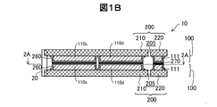
図1Bは、図1Aの圧電アクチュエーター10の1B−1B断面図である。圧電アクチュエーター10は、2つの圧電アクチュエーターユニット100を備える。2つの圧電アクチュエーターユニット100は、それぞれ、基板200と、基板200上に配置された5つの圧電素子110a〜110eを備える。なお、図1Bでは、2つの圧電素子110c,110dが図示され、他の3つの圧電素子110a,110b,110eは図示されていない。圧電素子110a〜110eは、平面視(図1A)で2枚の基板200が重なっている領域(振動部210の領域)において、2枚の基板200が互いに向かい合う側の面上にそれぞれ配置されている。また、同一の符号を付した2つの圧電素子、例えば、2つの圧電素子110aは、2枚の基板200の平面視で、互いに重なって見える位置にある。他の圧電素子110b〜110eについても同様である。2つの圧電アクチュエーターユニット100は、基板200を外側にして、圧電素子110a〜110eを2枚の基板200で挟むようにして配置されている。圧電素子110a〜110eは、保護層260により覆われている。ここで「保護層260」を「被覆部260」とも呼ぶ。2つの圧電アクチュエーターユニット100の被覆部260同士が、接着層270により接着されることにより、圧電アクチュエーター10が構成される。図1Aでは、凸部材20の形状について説明しなかったが、凸部材20は、略円柱形状をしており、2つの基板200に跨がっている。但し、凸部材20を球形状、楕円体形状として、各基板200のそれぞれ設ける様にしても良い。
1B is a 1B-1B cross-sectional view of the
圧電アクチュエーター10は、図1Bに示すように、支持部220の上にも、圧電素子110a〜110eと同じような層構造を有する圧電素子構造111を備える。ここで、圧電アクチュエーター10が基板200支持部220の上に圧電素子構造111を備えない場合、2つの支持部220は、隙間を空けて配置されることになる。一方、振動部210では、2枚の基板200の間に圧電素子110a〜110eが配置される。そのため、支持部220の上に圧電素子構造111を備えない場合、振動部210と支持部220とで厚さが異なる為、支持部220において、圧電アクチュエーターユニット100同士が接触せず、構造が不安定となる場合がある。支持部220の上に、圧電素子構造111を備えると、振動部210と支持部220とで厚さがほぼ一致し、支持部220においても、圧電アクチュエーターユニット100同士が接触するため、構造が安定しやすい。なお、圧電素子構造111に電圧が印加されて、伸張、収縮すると支持部220が振動するおそれがあるので、圧電素子構造111は、その圧電体に電圧が印加されないように、あるいは電圧が印加されても伸張、収縮しないように、構成されていることが好ましい。例えば、圧電素子構造111の圧電体を挟む2枚の電極を接地する、あるいは、短絡すればよい。
As shown in FIG. 1B, the
図1Cは、圧電アクチュエーター10の側面図である。図1Cでは、図示の都合上、振動部210における側面図を図示し、支持部220(図1A,1B)における側面図を省略している。図1Cからわかるように、被覆部260は、圧電素子110a〜110eの側面までも覆っている。
FIG. 1C is a side view of the
図2Aは、1つの圧電アクチュエーターユニット100の上面図である。図2Aでは、振動部210を図示し、支持部220は、第1接続部222と第2接続部223の一部を除き、図示が省略されている。さらに、圧電アクチュエーターユニット100のそれぞれの圧電素子110a〜110eは、被覆部260により覆われている。なお、第1接続部222と第2接続部223と接する領域では、被覆部260が無く、被覆部260は、圧電素子110a〜110eの周囲の少なくとも一部を覆っていると言える。なお、被覆部260は、圧電素子110a〜110eの周囲を全部覆っていても良い。
FIG. 2A is a top view of one
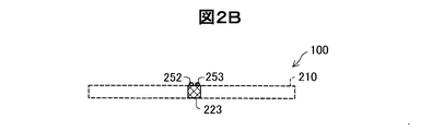
図2Bは、1つの圧電アクチュエーターユニット100の第2接続部223における断面図である。なお、図2Bでは、振動部210を破線で示している。振動部210上の圧電素子110a〜110e及び被覆部260は省略している。第2接続部223の上に配線252、253が見えるが、第2接続部223の上には、被覆部260は配置されていない。図示しないが、同様に、第1接続部222の上にも、被覆部260は配置されていない。このように、被覆部260は、圧電素子110a〜110eの全部を覆っている必要はなく、それらの周囲の一部(例えば配線252、253の部分)は覆っていなくてもよい。なお、被覆部260は、圧電素子110a〜110eの周囲を全部覆っていても良い。
FIG. 2B is a cross-sectional view of the second connecting
図3は、圧電アクチュエーターユニット100の断面を詳細に示す説明図である。圧電アクチュエーターユニット100は、基板200の上に絶縁層201、第1電極130、圧電体140、第2電極150、絶縁層240、配線層250、保護層260(被覆部260)の順に各部材が配置されている。絶縁層201は、基板200を他の電極(第1電極130と第2電極150と配線層250)から絶縁する。第1電極130と圧電体140と第2電極150は、圧電素子110a〜110eを構成する。絶縁層240は、圧電素子110a〜110eを覆い絶縁する。但し、絶縁層240は、圧電素子110a〜110eの第1電極130と第2電極150を、配線層250に接触させるためのコンタクトホールを備える。配線層250は、第1電極130と第2電極150に通電するための配線を構成する。保護層260(被覆部260)は、上述したように、圧電素子110a〜110eを保護する。
FIG. 3 is an explanatory diagram showing in detail the cross section of the
図4は、圧電アクチュエーターの製造工程を示すフローチャートである。図5は、圧電アクチュエーターユニットの製造工程を示す説明図である。ステップS100では、基板200上に絶縁層201を形成する。基板200として例えばSiウェハーを利用することができる。1枚のSiウェハー上には、圧電アクチュエーターユニット100を複数個形成することが可能である。絶縁層201としては、例えば、基板200の表面を熱酸化して形成されるSiO2層を利用することができる。なお、図1B等では、絶縁層201の図示が省略されている。絶縁層201としてアルミナ(Al2O3),アクリルやポリイミドなどの有機材料を用いることができる。なお、基板200が絶縁体である場合には、絶縁層201を形成する工程は省略可能である。
FIG. 4 is a flowchart showing a manufacturing process of the piezoelectric actuator. FIG. 5 is an explanatory view showing a manufacturing process of the piezoelectric actuator unit. In step S <b> 100, the insulating
ステップS110では、第1電極130を形成し、パターニングする。第1電極130の材料としては、Al(アルミニウム)や、Ni(ニッケル),Au(金),Pt(白金),Ir(イリジウム),Cu(銅)などの導電性の高い任意の材料を利用可能である。第1電極130は、例えば、スパッタリングにより形成でき、パターニングは、例えば、エッチングにより行うことが出来る。
In step S110, the
ステップS120では、第1電極130の上に圧電体140を形成し、パターニングする。圧電体140の材料としては、ABO3型のペロブスカイト構造を採るセラミックスなど、圧電効果を示す任意の材料を利用可能である。ABO3型のペロブスカイト構造を採るセラミックスとしては、例えばチタン酸ジルコン酸鉛(PZT),チタン酸バリウム,チタン酸鉛,ニオブ酸カリウム,ニオブ酸リチウム,タンタル酸リチウム,タングステン酸ナトリウム,酸化亜鉛,チタン酸バリウムストロンチウム(BST),タンタル酸ストロンチウムビスマス(SBT),メタニオブ酸鉛,亜鉛ニオブ酸鉛,スカンジウムニオブ酸鉛等を用いることが可能である。またセラミック以外の圧電効果を示す材料、例えばポリフッ化ビニリデン,水晶等を用いることも可能である。
In step S120, the
圧電体140の形成は、例えばゾル−ゲル法を用いて行うことが可能である。すなわち、圧電体材料のゾルゲル溶液を基板200(第1電極130)の上に滴下し、基板200を高速回転させることにより、第1電極130の上にゾルゲル溶液の薄膜を形成する。その後、200〜300℃の温度で仮焼きして第1電極130の上に圧電体材料の第1層を形成する。その後、ゾルゲル溶液の滴下、高速回転、仮焼き、のサイクルを複数回繰り返すことによって、第1電極130の上に所望の厚さまで圧電体層を形成する。なお、1サイクルで形成される圧電体の一層の厚みは、ゾルゲル溶液の粘度や、基板200の回転速度にも依存するが、約50nm〜150nmの厚さとなる。所望の厚さまで圧電体層を形成した後、600℃〜1000℃の温度で焼結することにより、圧電体140を形成する。焼結後の圧電体140の厚さを、50nm(0.05μm)以上20μm以下とすれば、小型の圧電アクチュエーター10を実現できる。なお、圧電体140の厚さを0.05μm以上とすれば、圧電体140の伸縮に応じて十分に大きな力を発生することができる。また、圧電体140の厚さを20μm以下とすれば、圧電体140に印加する電圧を600V以下としても十分に大きな力を発生することができる。その結果、圧電アクチュエーター10を駆動するための駆動回路(図示せず)を安価な素子で構成できる。なお、圧電体の厚さを400nm以上としてもよく、この場合、圧電素子で発生する力を大きく出来る。なお、仮焼きや焼結の温度、時間は、一例であり、圧電体材料により、適宜選択される。
The formation of the
ゾル−ゲル法を用いて圧電体材料の薄膜を形成した後に焼結した場合には、原料粉末を混合して焼結する従来の焼結法と比較して、(a)薄膜を形成しやすい、(b)格子方向を揃えて結晶化し易い、(c)圧電体の耐圧を向上できる、というメリットがある。 In the case of sintering after forming a thin film of piezoelectric material using the sol-gel method, (a) it is easier to form a thin film as compared with a conventional sintering method in which raw material powders are mixed and sintered. (B) It is easy to crystallize by aligning the lattice direction, and (c) it is possible to improve the breakdown voltage of the piezoelectric body.
第1の実施形態では、ステップS120において、アルゴンイオンビームを用いたイオンミリングにより、圧電体140のパターニングを行っている。なお、イオンミリングを用いてパターニングを行う代わりに、他の任意のパターニング方法(例えば、塩素系のガスを用いたドライエッチング)によりパターニングを行っても良い。
In the first embodiment, in step S120, the
ステップS130では、圧電体140の上に第2電極150を形成し、パターニングする。第2電極150の形成及びパターニングは、第1電極130と同様に、エッチングにより行うことが出来る。
In step S130, the
ステップS140では、第2電極150の上に絶縁層240を形成し、パターニングしてコンタクトホールを形成する。ステップS150では、絶縁層240の上に、銅または真鍮を用いて配線層250を形成し、配線層250をパターニングして配線を形成する。
In step S140, an insulating
図6は、配線層250による配線のパターンを示す説明図である。配線層250は、4つの配線251,252,253,254を有している。これらの配線251〜254は、固定部221から接続部222,または223を通って振動部210に渡るように形成されている。すなわち、配線251〜254は、振動部210と支持部220とを繋いで配置されている。第1配線251は、振動部210において、圧電素子110a,110d(図1)の第2電極150と接続される。同様に、第2配線252は、振動部210において、圧電素子110b,110cの第2電極150と接続され、第3配線253は、振動部210において、圧電素子110eの第2電極150と接続され、第4配線254は、振動部210において、圧電素子110a,110b,110c,110d,110eの第1電極130と接続される。また、これらの配線251〜254は、支持部220において、回路基板と接続される。なお、配線251〜254は、固定部221の圧電素子構造111とは接続されていない。
FIG. 6 is an explanatory diagram showing a wiring pattern by the
ステップS160では、保護層260(被覆部260)を形成する。被覆部260は、例えば、JCR(ジャンクション・コーティング・レジン)のようなシリコ−ン樹脂で形成される。なお、JCRの代わりに、エポキシ、ポリイミドなどの樹脂材料を用いて形成されてもよい。
In step S160, the protective layer 260 (covering portion 260) is formed. The covering
ステップS170では、エッチングにより、個々の基板200の形状を形成すると同時に、振動部210と、支持部220との間に隙間205を形成し、凸部材20を取り付けるための凹部216を形成する。
In step S <b> 170, the shape of each
図7は、2つの圧電アクチュエーターユニット100を用いて圧電アクチュエーター10を製造する工程を示す説明図である。ステップS180では、2つの圧電アクチュエーターユニット100を、互いに基板200が外側、圧電素子110a〜110eが内側を向き、同一符号の部材が面対称となるように配置する。その後、接着層270を用いて2つの圧電アクチュエーターユニット100の被覆部260同士を接着する。圧電素子110a〜110eは、被覆部260で覆われると共に、2枚の基板200に挟まれるので、ゴミなどによる外傷を受け難くなる。ステップS190では、凹部216に凸部材20を接着剤で接着する。
FIG. 7 is an explanatory diagram showing a process of manufacturing the
図8は、圧電アクチュエーター10と回路基板(図示せず)との接続部の説明図である。圧電アクチュエーター10は、支持部220において、外部の回路基板と接続される。支持部220では、支持部220(基板200)の上に絶縁層(図3の絶縁層201、図8では図示が省略)が形成され、その上に、圧電素子構造111、絶縁層240、配線252(図8のB−B断面では、配線層250の配線251〜254のうちの第2配線252が見えている)、保護層260(被覆部260)が順次形成されている。なお、なお、図5に示す工程では説明しなかったが、圧電アクチュエーターユニット100では、エッチングやイオンミリングを用いてパターニングを行っているため、積層方向から見たときの外形が上層ほど小さくなっている。第2配線252は、圧電素子構造111の上から、支持部220の圧電素子構造111の形成されていない位置まで、形成されている。2つの第2配線252の間には、無電解ニッケルめっき層280が形成されている。無電解ニッケルめっき層280の上には、金めっき層290が形成されている。
FIG. 8 is an explanatory diagram of a connection portion between the
図9は、圧電アクチュエーターと回路基板とを接続する工程を示す説明図である。ここでは、第2配線252を例にとって説明するが、他の配線251、253、254についても同様である。ステップS200では、第2配線252に無電解ニッケルめっき層280を形成する。無電解ニッケルめっき層280の形成では、先ず、パラジウムイオンを含む触媒溶液に圧電アクチュエーター10の端部を浸漬する。第2配線252は、銅または真鍮で形成されているため、銅の一部がパラジウムで置換されパラジウム金属が第2配線252に吸着する。
FIG. 9 is an explanatory diagram illustrating a process of connecting the piezoelectric actuator and the circuit board. Here, the
次に、圧電アクチュエーター10の端部を無電解ニッケル−リンめっき液に浸漬する。無電解ニッケル−リンめっき液は、ニッケルイオン(Ni2+)と、次亜リン酸イオン(H2PO2 −)とを含む。ニッケルイオン(Ni2+)と、次亜リン酸イオン(H2PO2 −)とは、パラジウムを触媒として以下の酸化還元反応を起こし、還元されたニッケルが第2配線252上に析出する。ニッケルは、第2配線252に沿って析出するため、基板200(支持部220)に沿って、基板200よりも外縁側に突き出る凸部285を有する形状となる。なお、ニッケルは、析出するときに、リンを含んでも良い。
Ni2+ + H2PO2 − + H2O → Ni + H2PO3 − + H2
Next, the end of the
Ni 2+ + H 2 PO 2 − + H 2 O → Ni + H 2 PO 3 − + H 2
ステップS210では、無電解ニッケルめっき層280上に金めっき層290を形成する。ステップS220では、圧電アクチュエーター10と回路基板300とを接合する。回路基板300は、フレキシブル基板上に配線が形成された構造を有する。金めっき層290を有する凸部285を回路基板300に押しつけることで、凸部285を回路基板300に食い込ませ、圧電アクチュエーター10と回路基板300とを接合し、電気的に接続させる。
In step S210, a
図10は、圧電アクチュエーター10の等価回路を示す説明図である。なお、圧電アクチュエーター10は、2つの圧電アクチュエーターユニット100を有しているが、図10では、一方の圧電アクチュエーターユニット100のみを図示している。図10から分かるように、5つの圧電素子110a〜110eの第1電極130は、配線254に接続され、回路基板300に接続されている。圧電素子110a,110dの第2電極150は、配線251に接続され、回路基板300に接続されている。圧電素子110b,110cの第2電極150は、配線252に接続され、回路基板300に接続されている。圧電素子110eの第2電極150は、配線253に接続され、回路基板300に接続されている。すなわち、圧電素子110は、3つのグループに分けられる。第1グループは、2つの圧電素子110a,110dを有する。第2グループは、2つの圧電素子110b,110cを有する。第3グループは、1つの圧電素子110eのみを有する。第1グループの圧電素子110a,110dは、互いに並列に接続され、回路基板300に接続されている。第2グループの圧電素子110b,110cは、互いに並列に接続され、回路基板300に接続されている。並列接続すると、各圧電素子110a〜110dに掛かる電圧を大きく出来る。第3グループの圧電素子110eは、単独で回路基板300に接続されている。なお、第1グループの圧電素子110a,110dは直列に接続されていても良い。この場合、電圧が印加されたときの圧電素子110aと110dの分極の向きは同じであることが好ましい。第2グループの圧電素子110b,110cについても同様に直列に接続されていてもよい。直列接続すると、容量を小さく出来る。
FIG. 10 is an explanatory diagram showing an equivalent circuit of the
回路基板300から、5つの圧電素子110a〜110eのうちの所定の圧電素子、例えば第1グループの圧電素子110a,110dの第1電極130と第2電極150との間に周期的に変化する交流電圧又は脈流電圧を印加することにより、圧電アクチュエーター10を超音波振動させて、凸部材20に接触するローター(被駆動体、被駆動部材)を所定の回転方向に回転させることが可能である。ここで、「脈流電圧」とは、交流電圧にDCオフセットを付加した電圧を意味し、脈流電圧の電圧(電界)の向きは、一方の電極から他方の電極に向かう一方向である。電流の向きは、第1電極130から第2電極150に向かうよりも第2電極150から第1電極130に向かう方が好ましい。また、第2グループの圧電素子110b,110cの第1電極130と第2電極150との間に交流電圧又は脈流電圧を印加することにより、凸部材20に接触するローターを逆方向に回転させることが可能である。すなわち、圧電アクチュエーター10は、圧電モーターとして機能する。
An alternating current that periodically changes between the
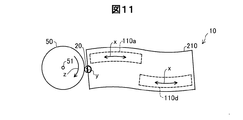
図11は、圧電アクチュエーター10の動作の例を示す説明図である。支持部220については、図示の都合上、省略している。圧電アクチュエーター10の凸部材20は、被駆動部材としてのローター50の外周に接触している。図11に示す例では、第1グループの2つの圧電素子110a,110dに交流電圧又は脈流電圧を印加しており、圧電素子110a,110dは図11の矢印xの方向に伸縮する。これに応じて、圧電アクチュエーター10の振動部210が振動部210の平面内で屈曲して蛇行形状(S字形状)に変形し、凸部材20の先端が矢印yの向きに往復運動するか、又は、楕円運動する。その結果、ローター50は、その中心51の周りに所定の方向z(図11では時計回り方向)に回転する。なお、回路基板300が、第2グループの2つの圧電素子110b,110c(図10)に交流電圧又は脈流電圧を印加する場合には、ローター50は逆方向に回転する。なお、中央の圧電素子110eに、交流電圧又は脈流電圧を印加すれば、圧電アクチュエーター10が長手方向に伸縮するので、凸部材20からローター50に与える力をより大きくすることが可能である。なお、圧電アクチュエーター10のこのような動作については、特開2004−320979号公報(又は、対応する米国特許第7224102号)に記載されており、その開示内容は参照により組み込まれる。
FIG. 11 is an explanatory diagram showing an example of the operation of the
以上、第1の実施形態によれば、圧電アクチュエーター10は、2枚の基板200の間に配置されている圧電素子110a〜110eと、圧電素子110a〜110eの周囲の少なくとも一部を覆っている被覆部260と、を備える。その結果、圧電素子110a〜110eは、2枚の基板200と被覆部260により保護されるので外傷を受け難い。
As described above, according to the first embodiment, the
また、第1の実施形態によれば、圧電アクチュエーター10は、平面視で少なくとも一部が重なって配置されている2枚の基板200と、平面視で2枚の基板200が重なっている領域(振動部210の領域)において、2枚の基板200が互いに向かい合う側の面上にそれぞれ配置されている圧電素子110a〜110eと、それぞれの圧電アクチュエーターユニット100において、圧電素子110a〜110eを覆っている被覆部260と、を備える。この形態によれば、圧電素子110a〜110eは、被覆部260に覆われていることに加え、少なくとも一部が重なって配置されている2枚の基板200の互いに向かい合う側の面上にそれぞれ配置されているので、2枚の基板200によっても保護され、外傷を受け難い。
In addition, according to the first embodiment, the
第1の実施形態によれば、各圧電アクチュエーターユニット100の圧電素子110a〜110eを覆っている被覆部260は、互いに接着層270で接着されていているので、2つの被覆部260が剥がれにくく、圧電素子110a〜110eが保護されやすい。
According to the first embodiment, since the covering
第1の実施形態によれば、基板200は、振動部210と、支持部220と、を有し、圧電素子110a〜110eは、振動部210に設けられていているので、支持部220の振動を低減するとともに、基板200の強度を上げることが出来る。
According to the first embodiment, the
上記形態において、被覆部260は、振動部210と、支持部220との接続部221,222において圧電素子110a〜110eを覆っていなかったが、圧電素子110a〜110eの全体を覆ってもよい。被覆部260は、圧電素子110a〜110eの全体を覆っていれば、圧電素子110a〜110eが更に保護され易い。
In the above embodiment, the covering
上記形態において、被覆部260が支持部220の周囲の少なくとも一部を覆う構成を採用しても良い。被覆部260は、支持部220の周囲の少なくとも一部を覆っていれば、支持部220を保護できる。
In the above embodiment, a configuration in which the covering
・第2の実施形態:
図12は、第2の実施形態の圧電アクチュエーター11を示す説明図である。第1の実施形態の圧電アクチュエーター10は、2つの圧電アクチュエーターユニット100を備えていたが、第2の実施形態の圧電アクチュエーター11は、圧電アクチュエーターユニット100を1つのみ備え、第1の実施形態の2つ目の圧電アクチュエーターユニット100の代わりに、圧電素子が配置されていない基板200を備えている。すなわち、第1の圧電アクチュエーターユニット100の圧電素子110a〜110eを、第1の圧電アクチュエーターユニット100の基板200と、圧電素子が配置されていない基板200とで挟んでいる。
Second embodiment:
FIG. 12 is an explanatory diagram illustrating the piezoelectric actuator 11 according to the second embodiment. The
第2の実施形態の圧電アクチュエーター11は、2枚の基板200と、2枚の基板200の間に配置されている圧電素子110a〜110eと、圧電素子の周囲の少なくとも一部を覆っている被覆部260と、を備える。第2の実施形態の圧電アクチュエーター11によれば、圧電素子110a〜110eは、2枚の基板200と被覆部260により保護される効果が高くなるので、第1の実施形態の圧電アクチュエーター10と同様に、外傷を受け難い。
The piezoelectric actuator 11 according to the second embodiment includes two
・第3の実施形態:
図13は、第3の実施形態の積層アクチュエーター12を示す説明図である。第1の実施形態では、圧電アクチュエーター10について説明した。この圧電アクチュエーター10を複数個用いて、基板200の面の法線方向に積層して、積層アクチュエーター12を構成することが可能である。なお、第2の実施形態の圧電アクチュエーター11を複数個用いて基板200の面の法線方向に積層してもよい。
Third embodiment:
FIG. 13 is an explanatory diagram illustrating the
・他の実施形態:
上述した圧電アクチュエーター10は、共振を利用することで被駆動部材に対して大きな力を与えることができるものであり、各種の装置に適用可能である。圧電アクチュエーター10は、例えば、ロボット(電子部品搬送装置(ICハンドラー)も含む)、投薬用ポンプ、時計のカレンダー送り装置、印刷装置(例えば紙送り機構。ただし、ヘッドに利用される圧電アクチュエーターでは、振動板を共振させないので、ヘッドには適用不可である。)等の各種の機器における駆動装置として用いることが出来る。以下、代表的な実施の形態について説明する。
Other embodiments:
The
図14は、上述の圧電アクチュエーター10を利用したロボット2050の一例を示す説明図である。ロボット2050は、複数本のリンク部2012(「リンク部材」とも呼ぶ)と、それらリンク部2012の間を回動又は屈曲可能な状態で接続する複数の関節部2020とを備えたアーム2010(「腕部」とも呼ぶ)を有している。それぞれの関節部2020には、上述した圧電アクチュエーター10が内蔵されており、圧電アクチュエーター10を用いて関節部2020を任意の角度だけ回動又は屈曲させることが可能である。アーム2010の先端には、ハンド2000が接続されている。ハンド2000は、一対の把持部2003を備えている。ハンド2000にも圧電アクチュエーター10が内蔵されており、圧電アクチュエーター10を用いて把持部2003を開閉して物を把持することが可能である。また、ハンド2000とアーム2010との間にも圧電アクチュエーター10が設けられており、圧電アクチュエーター10を用いてハンド2000をアーム2010に対して回転させることも可能である。
FIG. 14 is an explanatory view showing an example of a
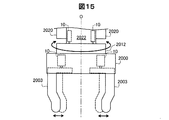
図15は、図14に示したロボット2050の手首部分の説明図である。手首の関節部2020は、手首回動部2022を挟持しており、手首回動部2022に手首のリンク部2012が、手首回動部2022の中心軸O周りに回動可能に取り付けられている。手首回動部2022は、圧電アクチュエーター10を備えており、圧電アクチュエーター10は、手首のリンク部2012及びハンド2000を中心軸O周りに回動させる。ハンド2000には、複数の把持部2003が立設されている。把持部2003の基端部はハンド2000内で移動可能となっており、この把持部2003の根元の部分に圧電アクチュエーター10が搭載されている。このため、圧電アクチュエーター10を動作させることで、把持部2003を移動させて対象物を把持することができる。
FIG. 15 is an explanatory diagram of the wrist portion of the
なお、ロボットとしては、単腕のロボットに限らず、腕の数が2以上の多腕ロボットにも圧電アクチュエーター10を適用可能である。ここで、手首の関節部2020やハンド2000の内部には、圧電アクチュエーター10の他に、力覚センサーやジャイロセンサー等の各種装置に電力を供給する電力線や、信号を伝達する信号線等が含まれ、非常に多くの配線が必要になる。従って、関節部2020やハンド2000の内部に配線を配置することは非常に困難だった。しかしながら、上述した実施形態の圧電アクチュエーター10は、通常の電動モーターや、従来の圧電駆動装置よりも駆動電流を小さくできるので、関節部2020(特に、アーム2010の先端の関節部)やハンド2000のような小さな空間でも配線を配置することが可能になる。
Note that the robot is not limited to a single-arm robot, and the
上記説明では、ハンド2000を備えるロボット2050を例にとって説明したが、ハンド2000は、ロボット2050の部品としてのみならず、単独の製品として構成されていても良い。
In the above description, the
図16は、上述の圧電アクチュエーター10を利用した指アシスト装置1000を示す説明図である。指アシスト装置1000は、第1の指アシスト部1001と、第2の指アシスト部1002と、ベース部材1003と、を備え、指700に装着される。第1の指アシスト部1001は、圧電アクチュエーター10と、減速機501と、指支持部701と、を備える。第2の指アシスト部1002は、圧電アクチュエーター10と、減速機502と、指支持部702と、バンド703と、を備える。バンド703を除き、第1の指アシスト部1001と第2の指アシスト部1002とは、ほぼ同じ構成である。バンド703は、指700の腹側から第2の指アシスト部1002を固定する。なお、バンド703は、第1の指アシスト部1001にも、設けられるが、図16では省略されている。指アシスト装置1000は、圧電アクチュエーター10により、指700の屈伸をアシストする。なお、本実施形態では、指アシスト装置1000は、指700の屈伸をアシストするものとして説明したが、指700の代わりにロボットのハンドを用い、ハンドと指アシスト装置1000とを一体化してもよい。この場合、ハンドが、圧電アクチュエーター10により駆動され、屈伸する。
FIG. 16 is an explanatory diagram showing a
図17は、上述の圧電アクチュエーター10を利用した送液ポンプ2200の一例を示す説明図である。送液ポンプ2200は、ケース2230内に、リザーバー2211と、チューブ2212と、圧電アクチュエーター10と、ローター2222と、減速伝達機構2223と、カム2202と、複数のフィンガー2213、2214、2215、2216、2217、2218、2219と、が設けられている。リザーバー2211は、輸送対象である液体を収容するための収容部である。チューブ2212は、リザーバー2211から送り出される液体を輸送するための管である。圧電アクチュエーター10の凸部材20は、ローター2222の側面に押し付けた状態で設けられており、圧電アクチュエーター10がローター2222を回転駆動する。ローター2222の回転力は減速伝達機構2223を介してカム2202に伝達される。フィンガー2213から2219はチューブ2212を閉塞させるための部材である。カム2202が回転すると、カム2202の突起部2202Aによってフィンガー2213から2219が順番に放射方向外側に押される。フィンガー2213から2219は、輸送方向上流側(リザーバー2211側)から順にチューブ2212を閉塞する。これにより、チューブ2212内の液体が順に下流側に輸送される。こうすれば、極く僅かな量を精度良く送液可能で、しかも小型な送液ポンプ2200を実現することができる。なお、各部材の配置は図示されたものには限られない。また、フィンガーなどの部材を備えず、ローター2222に設けられたボールなどがチューブ2212を閉塞する構成であってもよい。上記のような送液ポンプ2200は、インシュリンなどの薬液を人体に投与する投薬装置などに活用できる。ここで、上述した実施形態の圧電アクチュエーター10を用いることにより、従来の圧電駆動装置よりも駆動電流が小さくなるので、投薬装置の消費電力を抑制することができる。従って、投薬装置を電池駆動する場合は、特に有効である。
FIG. 17 is an explanatory diagram showing an example of a
以上、いくつかの実施例に基づいて本発明の実施の形態について説明してきたが、上記した発明の実施の形態は、本発明の理解を容易にするためのものであり、本発明を限定するものではない。本発明は、その趣旨並びに特許請求の範囲を逸脱することなく、変更、改良され得るとともに、本発明にはその等価物が含まれることはもちろんである。 The embodiments of the present invention have been described above based on some examples. However, the above-described embodiments of the present invention are for facilitating the understanding of the present invention and limit the present invention. It is not a thing. The present invention can be changed and improved without departing from the spirit and scope of the claims, and it is needless to say that the present invention includes equivalents thereof.
10,11…圧電アクチュエーター、12…積層アクチュエーター、20…凸部材、50…ローター、51…中心、100…圧電アクチュエーターユニット、110a,110b,110c,110d,110e…圧電素子、111…圧電素子構造、130…第1電極、140…圧電体、150…第2電極、200…基板、201…絶縁層、205…隙間、210…振動部、216…凹部、220…支持部、221…固定部、222…第1接続部、223…第2接続部、240…絶縁層、250…配線層、251…第1配線、252…第2配線、253…第3配線、254…第4配線、260…保護層(被覆部)、270…接着層、280…無電解ニッケルめっき層、285…凸部、290…金めっき層、300…回路基板、501,502…減速機、700…指、701,702…指支持部、703…バンド、1000…指アシスト装置、1001,1002…指アシスト部、1003…ベース部材、2000…ハンド、2003…把持部、2010…アーム、2012…リンク部、2020…関節部、2022…手首回動部、2050…ロボット、2200…送液ポンプ、2202…カム、2202A…突起部、2211…リザーバー、2212…チューブ、2213…フィンガー、2222…ローター、2223…減速伝達機構
DESCRIPTION OF
Claims (12)
圧電体を備えた複数の圧電素子であって、前記平面視で前記2つの基板が重なっている領域において、前記2つの基板の面上であって、前記2つの基板が互いに向かい合う側の面上の少なくとも四隅に配置された圧電体を有する複数の圧電素子と、
前記2つの基板の面上に分離して配置された前記複数の圧電素子のそれぞれ一部を覆っている被覆部と、
を備える、圧電アクチュエーター。 Two substrates that are partially overlapped in plan view;
A plurality of piezoelectric elements each including a piezoelectric body, in a region where the two substrates overlap in a plan view, on a surface of the two substrates and on a surface on the side where the two substrates face each other a plurality of piezoelectric elements having at least four corners placed by piezoelectric body,
A covering portion covering a part of each of the plurality of piezoelectric elements arranged separately on the surfaces of the two substrates ;
A piezoelectric actuator comprising:
前記複数の圧電素子は、前記振動部に設けられている、請求項1または2に記載の圧電アクチュエーター。 The substrate includes a vibration part and a support part that supports the vibration part,
It said plurality of piezoelectric elements, wherein is provided on the vibrating section, a piezoelectric actuator according to claim 1 or 2.
前記配線層と電気的に接続され、前記支持部に接続されている回路基板と、
を備える、請求項3乃至6のいずれか一項に記載の圧電アクチュエーター。 A wiring layer arranged to connect the vibrating part and the support part;
A circuit board electrically connected to the wiring layer and connected to the support;
A piezoelectric actuator according to any one of claims 3 to 6 , comprising:
Priority Applications (4)
| Application Number | Priority Date | Filing Date | Title |
|---|---|---|---|
| JP2015222564A JP6601174B2 (en) | 2015-11-13 | 2015-11-13 | Piezoelectric actuators, stacked actuators, piezoelectric motors, robots, hands and liquid pumps |
| CN201610959198.5A CN106849741B (en) | 2015-11-13 | 2016-11-03 | Piezoelectric actuator, laminated actuator, piezoelectric motor, robot, and robot hand |
| US15/349,202 US10497854B2 (en) | 2015-11-13 | 2016-11-11 | Piezoelectric actuator, stacked actuator, piezoelectric motor, robot, hand, and liquid transport pump |
| EP16198426.5A EP3176842B1 (en) | 2015-11-13 | 2016-11-11 | Piezoelectric actuator, piezoelectric motor, robot, and hand thereof |
Applications Claiming Priority (1)
| Application Number | Priority Date | Filing Date | Title |
|---|---|---|---|
| JP2015222564A JP6601174B2 (en) | 2015-11-13 | 2015-11-13 | Piezoelectric actuators, stacked actuators, piezoelectric motors, robots, hands and liquid pumps |
Publications (3)
| Publication Number | Publication Date |
|---|---|
| JP2017093194A JP2017093194A (en) | 2017-05-25 |
| JP2017093194A5 JP2017093194A5 (en) | 2018-11-08 |
| JP6601174B2 true JP6601174B2 (en) | 2019-11-06 |
Family
ID=57286380
Family Applications (1)
| Application Number | Title | Priority Date | Filing Date |
|---|---|---|---|
| JP2015222564A Active JP6601174B2 (en) | 2015-11-13 | 2015-11-13 | Piezoelectric actuators, stacked actuators, piezoelectric motors, robots, hands and liquid pumps |
Country Status (4)
| Country | Link |
|---|---|
| US (1) | US10497854B2 (en) |
| EP (1) | EP3176842B1 (en) |
| JP (1) | JP6601174B2 (en) |
| CN (1) | CN106849741B (en) |
Families Citing this family (2)
| Publication number | Priority date | Publication date | Assignee | Title |
|---|---|---|---|---|
| KR102049990B1 (en) * | 2013-03-28 | 2019-12-03 | 삼성전자주식회사 | Fusion protein comprising anti-c-Met antibody and VEGF binding fragment |
| JP6946893B2 (en) * | 2017-09-22 | 2021-10-13 | セイコーエプソン株式会社 | Piezoelectric drive devices, piezoelectric motors, robots, electronic component transfer devices, printers and projectors |
Family Cites Families (30)
| Publication number | Priority date | Publication date | Assignee | Title |
|---|---|---|---|---|
| US6108274A (en) * | 1995-12-15 | 2000-08-22 | Innovative Transducers, Inc. | Acoustic sensor and array thereof |
| JP3184117B2 (en) | 1997-05-23 | 2001-07-09 | セイコーインスツルメンツ株式会社 | Ultrasonic motor and electronic device with ultrasonic motor |
| DE19817038A1 (en) * | 1998-04-17 | 1999-10-21 | Philips Patentverwaltung | Piezomotor |
| JP4904656B2 (en) * | 2001-09-27 | 2012-03-28 | パナソニック株式会社 | Thin film piezoelectric element and method for manufacturing the same |
| JP3846271B2 (en) * | 2001-11-05 | 2006-11-15 | 松下電器産業株式会社 | Thin film piezoelectric element and manufacturing method thereof |
| JP2003272324A (en) * | 2002-03-15 | 2003-09-26 | Matsushita Electric Ind Co Ltd | Thin film piezoelectric element and manufacturing method therefor, and actuator |
| JP4145760B2 (en) | 2002-10-03 | 2008-09-03 | セイコーエプソン株式会社 | Piezoelectric actuator unit and manufacturing method thereof |
| US7132723B2 (en) * | 2002-11-14 | 2006-11-07 | Raytheon Company | Micro electro-mechanical system device with piezoelectric thin film actuator |
| US7068474B2 (en) * | 2002-12-03 | 2006-06-27 | Matsushita Electric Industrial Co., Ltd. | Thin film piezoelectric element; actuator, head support mechanism, and disc recording and reproducing device using the thin film piezoelectric element; and method of manufacturing the thin film piezoelectric element |
| JP2004320979A (en) | 2003-04-03 | 2004-11-11 | Seiko Epson Corp | Driving device and electric equipment |
| JP4141990B2 (en) | 2004-07-12 | 2008-08-27 | セイコーエプソン株式会社 | Piezoelectric actuators and equipment |
| JP2006080318A (en) | 2004-09-10 | 2006-03-23 | Nec Tokin Corp | Piezoelectric actuator |
| DE102004044138A1 (en) * | 2004-09-13 | 2006-03-30 | Robert Bosch Gmbh | Needle-shaped force sensor |
| JP2006340503A (en) * | 2005-06-02 | 2006-12-14 | Seiko Epson Corp | Piezoelectric actuator and apparatus equipped with it |
| JP4762109B2 (en) * | 2006-10-24 | 2011-08-31 | 株式会社日本自動車部品総合研究所 | Spark plug for internal combustion engine |
| JP2008147219A (en) | 2006-12-06 | 2008-06-26 | Nano Control:Kk | Laminated piezoelectric actuator, its driving method, positioning sensor, and displacement sensor |
| JP2008218953A (en) | 2007-03-08 | 2008-09-18 | Seiko Epson Corp | Piezoelectric vibrating body, electronic device, and manufacturing method of piezoelectric vibrating body |
| KR101319258B1 (en) * | 2007-04-19 | 2013-10-18 | 에스케이플래닛 주식회사 | Writable electronic paper display device and method for manufacturing thereof |
| JP2009128351A (en) | 2007-11-19 | 2009-06-11 | Microstone Corp | Vibrator used in gyro sensor |
| KR20120063345A (en) * | 2010-12-07 | 2012-06-15 | 삼성전기주식회사 | Haptic driving assembly and electronic device using the same |
| JP5665522B2 (en) | 2010-12-20 | 2015-02-04 | キヤノン株式会社 | Vibrating body and vibration type driving device |
| JP6008077B2 (en) | 2011-12-06 | 2016-10-19 | セイコーエプソン株式会社 | Actuators, robots, electronic component transfer devices, and electronic component inspection devices |
| DE102012212832A1 (en) * | 2012-07-23 | 2014-01-23 | Hilti Aktiengesellschaft | Assembly for a cable feedthrough |
| JP6172971B2 (en) | 2013-02-27 | 2017-08-02 | オリンパス株式会社 | Driving device and imaging device |
| KR102037068B1 (en) * | 2013-04-02 | 2019-10-30 | 삼성디스플레이 주식회사 | Energy recovery system for recovering pressure energy of touch input for a touch screen panel |
| JP6079931B2 (en) * | 2014-04-18 | 2017-02-15 | 株式会社村田製作所 | Press sensor |
| CN104022679B (en) * | 2014-06-25 | 2016-09-07 | 哈尔滨工业大学 | Clipping vertical curved composite ultrasonic motor oscillator |
| CN105375812A (en) * | 2014-08-13 | 2016-03-02 | 精工爱普生株式会社 | Piezoelectric driving device and driving method therefor, and robot and driving method therefor |
| JP6431984B2 (en) * | 2015-07-27 | 2018-11-28 | 富士フイルム株式会社 | Electroacoustic transducer film and method for producing the same, electroacoustic transducer, flexible display, vocal cord microphone, and sensor for musical instrument |
| JP6676935B2 (en) * | 2015-11-13 | 2020-04-08 | セイコーエプソン株式会社 | Electric devices, piezoelectric motors, robots, hands and liquid pumps |
-
2015
- 2015-11-13 JP JP2015222564A patent/JP6601174B2/en active Active
-
2016
- 2016-11-03 CN CN201610959198.5A patent/CN106849741B/en active Active
- 2016-11-11 EP EP16198426.5A patent/EP3176842B1/en active Active
- 2016-11-11 US US15/349,202 patent/US10497854B2/en active Active
Also Published As
| Publication number | Publication date |
|---|---|
| CN106849741B (en) | 2020-02-21 |
| EP3176842B1 (en) | 2022-03-02 |
| EP3176842A3 (en) | 2017-08-23 |
| EP3176842A2 (en) | 2017-06-07 |
| US10497854B2 (en) | 2019-12-03 |
| US20170141290A1 (en) | 2017-05-18 |
| JP2017093194A (en) | 2017-05-25 |
| CN106849741A (en) | 2017-06-13 |
Similar Documents
| Publication | Publication Date | Title |
|---|---|---|
| JP6405785B2 (en) | Piezoelectric drive device, robot, and drive method thereof | |
| JP6676935B2 (en) | Electric devices, piezoelectric motors, robots, hands and liquid pumps | |
| JP6398454B2 (en) | Piezoelectric drive device, robot, and drive method thereof | |
| JP6439466B2 (en) | Piezoelectric driving device, robot, and robot driving method | |
| JP2017017916A (en) | Piezoelectric driving device, robot, and driving method of piezoelectric driving device | |
| JP2017175696A (en) | Control circuit of piezoelectric drive device, piezoelectric drive device, ultrasonic motor, robot, hand, and pump | |
| US10147866B2 (en) | Piezoelectric driving device and driving method therefor, and robot and driving method therefor | |
| JP2017103953A (en) | Piezoelectric driving device for motor and manufacturing method of the same, motor, robot, and pump | |
| US20170008167A1 (en) | Piezoelectric drive device, robot, and method for driving piezoelectric drive device | |
| JP6601174B2 (en) | Piezoelectric actuators, stacked actuators, piezoelectric motors, robots, hands and liquid pumps | |
| JP2017069998A (en) | Piezoelectric drive device, manufacturing method for the same, motor, robot and pump | |
| JP6766328B2 (en) | Piezoelectric drive, robots, and methods of driving piezoelectric drives | |
| JP6503764B2 (en) | Piezoelectric element drive circuit and robot | |
| JP6432204B2 (en) | Piezoelectric drive device, robot, and drive method thereof | |
| JP2016040984A (en) | Piezoelectric drive device and drive method of the same, robot and drive method of the robot | |
| JP6641910B2 (en) | Piezoelectric driving device and manufacturing method thereof, motor, robot, and pump | |
| JP2016178737A (en) | Piezoelectric drive device, robot, and method of driving the robot | |
| JP6662007B2 (en) | Piezo drives, motors, robots, and pumps | |
| JP2017135935A (en) | Piezoelectric actuator, piezoelectric motor, robot, hand and feed pump | |
| JP6432369B2 (en) | Piezoelectric driving device, robot, and robot driving method | |
| JP2017112650A (en) | Vibrating body, laminated vibrating body, piezoelectric actuator, piezoelectric motor, robot, hand, and liquid feed pump | |
| JP6413461B2 (en) | Piezoelectric driving device and driving method thereof, robot and driving method thereof | |
| JP2017135936A (en) | Piezoelectric actuator, piezoelectric motor, robot, hand, feeding pump, and adjustment method of piezoelectric actuator | |
| JP2016144269A (en) | Piezoelectric drive device, robot, and driving method of robot | |
| JP2016158380A (en) | Piezoelectric element drive circuit and robot |
Legal Events
| Date | Code | Title | Description |
|---|---|---|---|
| A521 | Request for written amendment filed |
Free format text: JAPANESE INTERMEDIATE CODE: A523 Effective date: 20180927 |
|
| A621 | Written request for application examination |
Free format text: JAPANESE INTERMEDIATE CODE: A621 Effective date: 20180927 |
|
| A131 | Notification of reasons for refusal |
Free format text: JAPANESE INTERMEDIATE CODE: A131 Effective date: 20190625 |
|
| A977 | Report on retrieval |
Free format text: JAPANESE INTERMEDIATE CODE: A971007 Effective date: 20190628 |
|
| A521 | Request for written amendment filed |
Free format text: JAPANESE INTERMEDIATE CODE: A523 Effective date: 20190809 |
|
| TRDD | Decision of grant or rejection written | ||
| A01 | Written decision to grant a patent or to grant a registration (utility model) |
Free format text: JAPANESE INTERMEDIATE CODE: A01 Effective date: 20190910 |
|
| A61 | First payment of annual fees (during grant procedure) |
Free format text: JAPANESE INTERMEDIATE CODE: A61 Effective date: 20190923 |
|
| R150 | Certificate of patent or registration of utility model |
Ref document number: 6601174 Country of ref document: JP Free format text: JAPANESE INTERMEDIATE CODE: R150 |