JP6614499B2 - Automatic drain discharge device - Google Patents
Automatic drain discharge device Download PDFInfo
- Publication number
- JP6614499B2 JP6614499B2 JP2016156421A JP2016156421A JP6614499B2 JP 6614499 B2 JP6614499 B2 JP 6614499B2 JP 2016156421 A JP2016156421 A JP 2016156421A JP 2016156421 A JP2016156421 A JP 2016156421A JP 6614499 B2 JP6614499 B2 JP 6614499B2
- Authority
- JP
- Japan
- Prior art keywords
- drain
- float
- case
- housing
- valve body
- Prior art date
- Legal status (The legal status is an assumption and is not a legal conclusion. Google has not performed a legal analysis and makes no representation as to the accuracy of the status listed.)
- Active
Links
- 230000002093 peripheral effect Effects 0.000 claims description 33
- 239000007788 liquid Substances 0.000 claims description 16
- NJPPVKZQTLUDBO-UHFFFAOYSA-N novaluron Chemical compound C1=C(Cl)C(OC(F)(F)C(OC(F)(F)F)F)=CC=C1NC(=O)NC(=O)C1=C(F)C=CC=C1F NJPPVKZQTLUDBO-UHFFFAOYSA-N 0.000 claims description 9
- 238000007599 discharging Methods 0.000 claims description 4
- 239000012530 fluid Substances 0.000 description 26
- 239000000126 substance Substances 0.000 description 4
- 239000000463 material Substances 0.000 description 3
- 229920003002 synthetic resin Polymers 0.000 description 3
- 239000000057 synthetic resin Substances 0.000 description 3
- 230000007423 decrease Effects 0.000 description 2
- 238000006073 displacement reaction Methods 0.000 description 2
- 230000014759 maintenance of location Effects 0.000 description 2
- 239000012780 transparent material Substances 0.000 description 2
- 238000004140 cleaning Methods 0.000 description 1
- 239000000428 dust Substances 0.000 description 1
- 230000000694 effects Effects 0.000 description 1
- 238000005187 foaming Methods 0.000 description 1
- 230000005484 gravity Effects 0.000 description 1
- JEIPFZHSYJVQDO-UHFFFAOYSA-N iron(III) oxide Inorganic materials O=[Fe]O[Fe]=O JEIPFZHSYJVQDO-UHFFFAOYSA-N 0.000 description 1
- 230000007257 malfunction Effects 0.000 description 1
- 238000012986 modification Methods 0.000 description 1
- 230000004048 modification Effects 0.000 description 1
- 238000005192 partition Methods 0.000 description 1
- 230000000717 retained effect Effects 0.000 description 1
- 239000007787 solid Substances 0.000 description 1
- 125000006850 spacer group Chemical group 0.000 description 1
- 238000005496 tempering Methods 0.000 description 1
- XLYOFNOQVPJJNP-UHFFFAOYSA-N water Substances O XLYOFNOQVPJJNP-UHFFFAOYSA-N 0.000 description 1
Images


Classifications
-
- F—MECHANICAL ENGINEERING; LIGHTING; HEATING; WEAPONS; BLASTING
- F16—ENGINEERING ELEMENTS AND UNITS; GENERAL MEASURES FOR PRODUCING AND MAINTAINING EFFECTIVE FUNCTIONING OF MACHINES OR INSTALLATIONS; THERMAL INSULATION IN GENERAL
- F16T—STEAM TRAPS OR LIKE APPARATUS FOR DRAINING-OFF LIQUIDS FROM ENCLOSURES PREDOMINANTLY CONTAINING GASES OR VAPOURS
- F16T1/00—Steam traps or like apparatus for draining-off liquids from enclosures predominantly containing gases or vapours, e.g. gas lines, steam lines, containers
- F16T1/20—Steam traps or like apparatus for draining-off liquids from enclosures predominantly containing gases or vapours, e.g. gas lines, steam lines, containers with valves controlled by floats
- F16T1/26—Steam traps or like apparatus for draining-off liquids from enclosures predominantly containing gases or vapours, e.g. gas lines, steam lines, containers with valves controlled by floats of upright-open-bucket type
-
- F—MECHANICAL ENGINEERING; LIGHTING; HEATING; WEAPONS; BLASTING
- F16—ENGINEERING ELEMENTS AND UNITS; GENERAL MEASURES FOR PRODUCING AND MAINTAINING EFFECTIVE FUNCTIONING OF MACHINES OR INSTALLATIONS; THERMAL INSULATION IN GENERAL
- F16K—VALVES; TAPS; COCKS; ACTUATING-FLOATS; DEVICES FOR VENTING OR AERATING
- F16K31/00—Actuating devices; Operating means; Releasing devices
- F16K31/12—Actuating devices; Operating means; Releasing devices actuated by fluid
- F16K31/18—Actuating devices; Operating means; Releasing devices actuated by fluid actuated by a float
- F16K31/34—Actuating devices; Operating means; Releasing devices actuated by fluid actuated by a float acting on pilot valve controlling the cut-off apparatus
-
- F—MECHANICAL ENGINEERING; LIGHTING; HEATING; WEAPONS; BLASTING
- F16—ENGINEERING ELEMENTS AND UNITS; GENERAL MEASURES FOR PRODUCING AND MAINTAINING EFFECTIVE FUNCTIONING OF MACHINES OR INSTALLATIONS; THERMAL INSULATION IN GENERAL
- F16T—STEAM TRAPS OR LIKE APPARATUS FOR DRAINING-OFF LIQUIDS FROM ENCLOSURES PREDOMINANTLY CONTAINING GASES OR VAPOURS
- F16T1/00—Steam traps or like apparatus for draining-off liquids from enclosures predominantly containing gases or vapours, e.g. gas lines, steam lines, containers
- F16T1/20—Steam traps or like apparatus for draining-off liquids from enclosures predominantly containing gases or vapours, e.g. gas lines, steam lines, containers with valves controlled by floats
- F16T1/22—Steam traps or like apparatus for draining-off liquids from enclosures predominantly containing gases or vapours, e.g. gas lines, steam lines, containers with valves controlled by floats of closed-hollow-body type
-
- F—MECHANICAL ENGINEERING; LIGHTING; HEATING; WEAPONS; BLASTING
- F16—ENGINEERING ELEMENTS AND UNITS; GENERAL MEASURES FOR PRODUCING AND MAINTAINING EFFECTIVE FUNCTIONING OF MACHINES OR INSTALLATIONS; THERMAL INSULATION IN GENERAL
- F16T—STEAM TRAPS OR LIKE APPARATUS FOR DRAINING-OFF LIQUIDS FROM ENCLOSURES PREDOMINANTLY CONTAINING GASES OR VAPOURS
- F16T1/00—Steam traps or like apparatus for draining-off liquids from enclosures predominantly containing gases or vapours, e.g. gas lines, steam lines, containers
- F16T1/12—Steam traps or like apparatus for draining-off liquids from enclosures predominantly containing gases or vapours, e.g. gas lines, steam lines, containers with valves controlled by excess or release of pressure
- F16T1/14—Steam traps or like apparatus for draining-off liquids from enclosures predominantly containing gases or vapours, e.g. gas lines, steam lines, containers with valves controlled by excess or release of pressure involving a piston, diaphragm, or bellows, e.g. displaceable under pressure of incoming condensate
-
- F—MECHANICAL ENGINEERING; LIGHTING; HEATING; WEAPONS; BLASTING
- F16—ENGINEERING ELEMENTS AND UNITS; GENERAL MEASURES FOR PRODUCING AND MAINTAINING EFFECTIVE FUNCTIONING OF MACHINES OR INSTALLATIONS; THERMAL INSULATION IN GENERAL
- F16T—STEAM TRAPS OR LIKE APPARATUS FOR DRAINING-OFF LIQUIDS FROM ENCLOSURES PREDOMINANTLY CONTAINING GASES OR VAPOURS
- F16T1/00—Steam traps or like apparatus for draining-off liquids from enclosures predominantly containing gases or vapours, e.g. gas lines, steam lines, containers
- F16T1/20—Steam traps or like apparatus for draining-off liquids from enclosures predominantly containing gases or vapours, e.g. gas lines, steam lines, containers with valves controlled by floats
- F16T1/22—Steam traps or like apparatus for draining-off liquids from enclosures predominantly containing gases or vapours, e.g. gas lines, steam lines, containers with valves controlled by floats of closed-hollow-body type
- F16T1/24—Steam traps or like apparatus for draining-off liquids from enclosures predominantly containing gases or vapours, e.g. gas lines, steam lines, containers with valves controlled by floats of closed-hollow-body type using levers
-
- F—MECHANICAL ENGINEERING; LIGHTING; HEATING; WEAPONS; BLASTING
- F16—ENGINEERING ELEMENTS AND UNITS; GENERAL MEASURES FOR PRODUCING AND MAINTAINING EFFECTIVE FUNCTIONING OF MACHINES OR INSTALLATIONS; THERMAL INSULATION IN GENERAL
- F16T—STEAM TRAPS OR LIKE APPARATUS FOR DRAINING-OFF LIQUIDS FROM ENCLOSURES PREDOMINANTLY CONTAINING GASES OR VAPOURS
- F16T1/00—Steam traps or like apparatus for draining-off liquids from enclosures predominantly containing gases or vapours, e.g. gas lines, steam lines, containers
- F16T1/38—Component parts; Accessories
- F16T1/383—Valve closing members or valve seats
-
- F—MECHANICAL ENGINEERING; LIGHTING; HEATING; WEAPONS; BLASTING
- F16—ENGINEERING ELEMENTS AND UNITS; GENERAL MEASURES FOR PRODUCING AND MAINTAINING EFFECTIVE FUNCTIONING OF MACHINES OR INSTALLATIONS; THERMAL INSULATION IN GENERAL
- F16T—STEAM TRAPS OR LIKE APPARATUS FOR DRAINING-OFF LIQUIDS FROM ENCLOSURES PREDOMINANTLY CONTAINING GASES OR VAPOURS
- F16T1/00—Steam traps or like apparatus for draining-off liquids from enclosures predominantly containing gases or vapours, e.g. gas lines, steam lines, containers
- F16T1/38—Component parts; Accessories
- F16T1/386—Actuating mechanisms for lift valves
-
- F—MECHANICAL ENGINEERING; LIGHTING; HEATING; WEAPONS; BLASTING
- F16—ENGINEERING ELEMENTS AND UNITS; GENERAL MEASURES FOR PRODUCING AND MAINTAINING EFFECTIVE FUNCTIONING OF MACHINES OR INSTALLATIONS; THERMAL INSULATION IN GENERAL
- F16T—STEAM TRAPS OR LIKE APPARATUS FOR DRAINING-OFF LIQUIDS FROM ENCLOSURES PREDOMINANTLY CONTAINING GASES OR VAPOURS
- F16T1/00—Steam traps or like apparatus for draining-off liquids from enclosures predominantly containing gases or vapours, e.g. gas lines, steam lines, containers
- F16T1/20—Steam traps or like apparatus for draining-off liquids from enclosures predominantly containing gases or vapours, e.g. gas lines, steam lines, containers with valves controlled by floats
-
- Y—GENERAL TAGGING OF NEW TECHNOLOGICAL DEVELOPMENTS; GENERAL TAGGING OF CROSS-SECTIONAL TECHNOLOGIES SPANNING OVER SEVERAL SECTIONS OF THE IPC; TECHNICAL SUBJECTS COVERED BY FORMER USPC CROSS-REFERENCE ART COLLECTIONS [XRACs] AND DIGESTS
- Y10—TECHNICAL SUBJECTS COVERED BY FORMER USPC
- Y10T—TECHNICAL SUBJECTS COVERED BY FORMER US CLASSIFICATION
- Y10T137/00—Fluid handling
- Y10T137/2931—Diverse fluid containing pressure systems
- Y10T137/3003—Fluid separating traps or vents
- Y10T137/3021—Discriminating outlet for liquid
- Y10T137/304—With fluid responsive valve
- Y10T137/3052—Level responsive
- Y10T137/3068—Float
- Y10T137/308—With pressure balanced outlet valve
Description
本発明は、自動ドレン排出装置に関する。 The present invention relates to an automatic drain discharge device.
従来から、流体圧回路中のコンプレッサやアフタークーラ等の各種流体圧機器から排出されたドレンを一時的に貯留し、一定量溜まる毎に自動的に外部に排出する自動ドレン排出装置が知られている。 Conventionally, there has been known an automatic drain discharge device that temporarily stores drain discharged from various fluid pressure devices such as a compressor and an aftercooler in a fluid pressure circuit, and automatically discharges the drain every time a certain amount is accumulated. Yes.
例えば、特許文献1には、図6に示される自動ドレン排出装置1が開示されている。 For example, Patent Document 1 discloses an automatic drain discharge device 1 shown in FIG.
この自動ドレン排出装置1は、ドレンを一時的に貯留するケース2と、ケース2の底部の開口部3に配設されたハウジング4と、ハウジング4に設けられたドレン排出孔5を開閉するスプール式のドレン弁体6と、ドレン弁体6に付設されたピストン7と、ピストン7を収容するシリンダ8と、シリンダ8の外側に配設されるフロート9と、ピストン7にパイロット圧を作用させることによりドレン弁体6を駆動させるパイロット弁機構10と、を備えている。
The automatic drain discharge device 1 includes a
ケース2の上部の開口部から滴下するドレンは、該ケース2の底部に溜まる。溜まったドレン11の液位に応じてフロート9が上昇すると、フロート9に連結されたレバー12が揺動し、揺動したレバー12がパイロット弁13を上昇させて、パイロット弁13がパイロット弁座14から離間し、パイロット室15に圧力流体が流入する。圧力流体の作用下に、ピストン7及びピストン7に付設されたドレン弁体6が下方へ押し下げられ、ドレン弁体6がドレン弁座16から離間する。これにより、ケース2内のドレンがドレン排出孔5から排出される。
The drain dripping from the opening at the top of the
ところで、コンプレッサ等の流体圧機器から排出されるドレンには、流体だけでなく固形又は泥状の異物が含まれている。異物とは、例えば、圧力流体に含まれる塵埃や流体圧機器に用いられる配管中の錆等である。 By the way, the drain discharged from a fluid pressure device such as a compressor contains not only fluid but also solid or mud foreign matter. The foreign matter is, for example, dust contained in pressure fluid, rust in piping used for fluid pressure equipment, or the like.
ここで、特許文献1記載の自動ドレン排出装置1では、ドレンはシリンダ8の下部に設けられた開口部17からドレン弁体6側に入り込む。しかしながら、ハウジング4の上端部がケース2の底部よりも上位に位置するために、ドレンに含まれる異物がケース2の底部(液溜まり部)に滞留してしまうという問題がある。
Here, in the automatic drain discharge device 1 described in Patent Document 1, the drain enters the drain valve body 6 side from the
このような異物は、ドレンの排出の支障の原因となるため、ドレンとともに速やかにケース2の外部へ排出されることが好ましい。
Since such foreign matters cause troubles in draining, it is preferable that the foreign matters are quickly discharged to the outside of the
本発明はこのような課題を考慮してなされたものであり、ドレン内に含まれる異物を確実且つ速やかに外部に排出して異物の滞留による不具合を阻止し、長期に亘って安定的に作動することが可能な自動ドレン排出装置を提供することを目的とする。 The present invention has been made in view of such problems, and foreign matter contained in the drain is reliably and promptly discharged to the outside to prevent problems due to the stay of foreign matter, and operates stably over a long period of time. An object of the present invention is to provide an automatic drain discharge device capable of performing the above.
本発明に係る自動ドレン排出装置は、底部に開口部を有するケースと、前記開口部に配設され、ドレン排出孔を有する第1のハウジングと、前記ドレン排出孔に設けられるドレン弁座と、前記ドレン弁座を開閉するドレン弁体と、前記ケース内のドレンの液位により上下動するフロートと、前記フロートの上下動によりパイロット圧を受圧体に作用させて前記ドレン弁体を駆動するパイロット弁機構と、を備える自動ドレン排出装置であって、前記ケースの前記底部は、上方から下方を指向して徐々に内径が狭くなるように形成され、前記第1のハウジングは、前記ケースの内部と前記ドレン排出孔とを連通する連通孔を有し、前記連通孔の底面は、前記ドレン排出孔に向かって傾斜する傾斜面を有し、前記連通孔の前記底面における最も上方且つ外側の縁部は、前記ケースの内周面における最も下方且つ前記開口部寄りの縁部と面一又はより低い位置に設けられることを特徴とする。 An automatic drain discharge device according to the present invention includes a case having an opening at the bottom, a first housing disposed in the opening and having a drain discharge hole, a drain valve seat provided in the drain discharge hole, A drain valve body that opens and closes the drain valve seat, a float that moves up and down by the liquid level of the drain in the case, and a pilot that drives the drain valve body by applying a pilot pressure to the pressure receiving body by the vertical movement of the float An automatic drain discharge device comprising a valve mechanism, wherein the bottom portion of the case is formed so as to be gradually narrowed from the upper side toward the lower side, and the first housing is formed inside the case. And a drain hole that communicates with the drain discharge hole, and the bottom surface of the communication hole has an inclined surface that is inclined toward the drain discharge hole, and is the top of the bottom surface of the communication hole. And the outer edge, and which are located in the lowermost and edge flush with or lower than the position of the opening near the inner peripheral surface of the case.
このような構成によれば、ケースの底部に、ドレン排出孔に向かって連続する湾曲面及び傾斜面が形成される。このため、異物を確実且つ速やかに外部に排出することができ、異物の滞留による不具合を阻止することができる。 According to such a structure, the curved surface and inclined surface which continue toward a drain discharge hole are formed in the bottom part of a case. For this reason, a foreign material can be discharged | emitted reliably and promptly outside, and the malfunction by the retention of a foreign material can be prevented.
また、前記ドレン弁体は、前記ドレン弁座を下方から開閉するポペット式であり、前記受圧体は、ダイヤフラムであるとよい。 The drain valve body may be a poppet type that opens and closes the drain valve seat from below, and the pressure receiving body may be a diaphragm.
このような構成によれば、ドレン弁座の開閉及びパイロット圧によるドレン弁体の駆動に際し、ポペット式のドレン弁体もダイヤフラムも他の部材と摺動する部分を有しない。このため、摺動部に対する異物の噛み込み等の不具合を生じるおそれがなく、異物による不具合を予め阻止することができる。 According to such a configuration, when the drain valve seat is opened and closed and the drain valve body is driven by the pilot pressure, neither the poppet type drain valve body nor the diaphragm has a portion that slides with other members. For this reason, there is no possibility that problems such as biting of foreign matter with respect to the sliding portion will occur, and it is possible to prevent problems due to foreign matter in advance.
さらに、前記第1のハウジングの上方に第2のハウジングが設けられ、前記第1のハウジングは、前記ドレン弁体と前記ドレン弁座と前記受圧体を収容し、前記第2のハウジングは、前記第1のハウジングの上部に嵌合する台座と、前記台座の上面中央に設けられ、前記フロートが挿通される案内筒部と、を含み、前記フロートは、前記第2のハウジングの前記台座よりも上方に配置されることが好ましい。 Further, a second housing is provided above the first housing, the first housing accommodates the drain valve body, the drain valve seat, and the pressure receiving body, and the second housing A pedestal that fits into the upper portion of the first housing; and a guide tube portion that is provided at the center of the upper surface of the pedestal and through which the float is inserted. The float is more than the pedestal of the second housing. It is preferable to be arranged on the upper side.
このような構成によれば、フロートは、ドレンの液位が第2のハウジングの台座の位置を超えてから、上方への変位を開始するので、ケースの内部により多くのドレンを貯留することができる。このため、ドレン排出動作1回当りのドレン排出量を大きくすることができ、より多くのドレンで異物を押し流すことができるので、異物を確実に排出することが可能となる。 According to such a configuration, since the float starts displacement upward after the liquid level of the drain exceeds the position of the base of the second housing, more float can be stored in the case. it can. For this reason, the drain discharge amount per drain discharge operation can be increased, and the foreign matter can be swept away by a larger amount of drain, so that the foreign matter can be reliably discharged.
またさらに、前記パイロット弁機構は、前記案内筒部の上端に設けられる着座部と、前記着座部を開閉するパイロット弁体と、前記パイロット弁体に連結されるレバーと、を含み、前記フロートは、上端周縁部に径方向に拡径したフランジ部を有し、前記ドレンの液位の上昇に伴い前記フロートが上方へ変位したときに、前記フランジ部が前記レバーを押し上げて、前記着座部が開放されることが好ましい。 Furthermore, the pilot valve mechanism includes a seat portion provided on the upper end of the guide tube portion, and a pilot valve body for opening and closing the seat, comprises a lever which is connected to the pilot valve body, said float has a flange portion which is enlarged radially upper peripheral portion, when the float with increasing liquid level in the drain is displaced upward, the flange portion pushes up the lever, the seat is It is preferably opened.
このような構成によれば、フランジ部を有しない従来のフロートと比べて、レバーの回動支点からフロートの浮力の作用点までの長さを大きくすることができる。このため、フロート全体としては外径を小さく保ちつつ、レバーの揺動に必要な梃子の力を得ることができ、フロートの外周面とケースの内周面との隙間に、より多くのドレンを貯留することが可能となる。 According to such a structure, compared with the conventional float which does not have a flange part, the length from the rotation fulcrum of a lever to the action point of the buoyancy of a float can be enlarged. For this reason, the overall force of the float can be obtained while maintaining the outer diameter small, and the lever force required for rocking the lever can be obtained, and more drain is placed in the gap between the outer peripheral surface of the float and the inner peripheral surface of the case. It can be stored.
本発明によれば、ケースの底部に、ドレン排出孔に向かって連続する湾曲面及び傾斜面が形成される。このため、ドレンに含まれる異物を確実且つ速やかに外部に排出して、異物の滞留による不具合を阻止することができ、その結果、長期に亘って安定的に作動することが可能となる。 According to the present invention, a curved surface and an inclined surface that are continuous toward the drain discharge hole are formed at the bottom of the case. For this reason, the foreign matter contained in the drain can be reliably and promptly discharged to the outside to prevent a problem due to the retention of the foreign matter, and as a result, it is possible to operate stably over a long period of time.
以下、本発明に係る自動ドレン排出装置20について好適な実施形態を挙げ、添付の図面を参照して詳細に説明する。
Hereinafter, preferred embodiments of the automatic
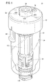
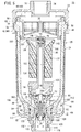
この自動ドレン排出装置20は、図1及び図2に示されるように、蓋部材22と、蓋部材22の下部に液密に取り付けられる有底円筒状のケース24と、ケース24を囲繞してこれを保護するケースガード26と、を備える。ケース24の底部には開口部28が画成され、この開口部28には、ドレンハウジング(第1のハウジング)30が配設される。このドレンハウジング30には、ドレンの自動排出機能に係る各部材(後述する)が一体的に組み付けられる。
As shown in FIGS. 1 and 2, the automatic
蓋部材22は下方が開口して、上部中央には、図において上方へと突出する雌ねじ部32が設けられる。雌ねじ部32の軸心に沿う開口は、ドレン導入孔34として用いられる。雌ねじ部32の近傍には小径のブリードバルブ取付孔36が設けられる。
The
ブリードバルブ取付孔36は、ケース24の内部の圧力流体を外部に放出するための図示しないブリードバルブを取り付けるためのものである。ケース24内の圧力流体がブリードバルブから外部へ放出されると、ケース24の内圧が下がり差圧が発生して、圧力流体に流れが生じる。ドレン配管が細く長い場合やドレン導入孔34が小さい場合等ドレンがケース24内へ流入し難いときであっても、ブリードバルブによって生じた圧力流体の流れによって、ドレンはケース24内に流入し易くなる。また、ドレン導入孔34を挟んで対称に配置された小穴は、自動ドレン排出装置20を図示しない壁面等に取り付けるためのブラケット用取付孔である。
The bleed
蓋部材22の下部には、図2に示されるように、ケース24が嵌合する。ケース24の上端開口部に、エレメント(フィルタエレメント)38が装着される。このエレメント38は、環状の支承部40と該支承部40から下方向に伸びる環状壁部42からなる支持枠44と、支持枠44の下部に一体的に形成された略円錐状の底板部46と、から構成される。支持枠44の内部には、環状で且つメッシュ状のフィルタ本体48が設けられる。なお、底板部46中央の中空略円筒状の突起50は、分解清掃等のためにエレメント38をケース24から取り外す際、ユーザーが指で摘んでエレメント38を引き上げるための摘みである。
As shown in FIG. 2, a
支持枠44を形成する環状壁部42の上端部は、径方向外方を指向して多段に折り曲げられてそのフランジ部分がケース24で保持される。環状壁部42の下端部は、上方を指向して折り返され、外周面がケース24の内周面に当接する。これにより、エレメント38はケース24に対して固定される。
The upper end portion of the
ケース24は、前記の通り、上部が開口した略円筒状であって、合成樹脂等の透明な材料から形成される。ケース24の底部は、上方から下方を指向して徐々に内径を狭くし、最も内径の小さい底部中央には、肉厚部分を利用して略八角形状の開口部28が画成される。開口部28の内周縁には、ケース24の内周面よりも一段低い段部52が設けられ、この段部52には、後述するドレンハウジング30のフランジ部54が着座する。
As described above, the
ケース24の周側面において、上方の開口端部近傍には、径方向外方へ突出する複数の係合突部56と、外周面を周回する周溝58が設けられる。係合突部56は、蓋部材22の内周壁に設けられた係合用凹部60に係合し、これにより、ケース24は蓋部材22に着脱可能に取り付けられる。周溝58にはOリング62が配設され、ケース24と蓋部材22の液密又は気密状態が確保される。
On the peripheral side surface of the
一方、ケースガード26は、ケース24の外側にあってこれを囲繞して保護する。ケースガード26は、ケース24と同様に、略円筒状であり、合成樹脂等の透明な材料から形成される。ケースガード26は、図1に示されるロックボタン64を介して、蓋部材22に着脱自在に固定される。
On the other hand, the
ドレンハウジング30は、図3及び図4に示されるように、全体として、上端及び下端が開口した略円筒状に形成される。ドレンハウジング30は、内側にドレン排出孔66が設けられたドレン排出部68と、ドレン排出部68の上部に設けられ、周側面から径方向外方に突出するフランジ部54と、フランジ部54の上方に設けられ、内部に後述するダイヤフラム(受圧体)70が収容される受圧部72と、を含む。
As shown in FIGS. 3 and 4, the
ドレン排出部68は、その内側にドレンを排出する流路としてのドレン排出孔66を有し、周壁には、周方向に沿って傾斜して開口する係合孔74が設けられる。係合孔74の上方の周側面には、同芯的に周溝76及び周溝78が所定間隔離間して形成される。周溝76にはOリング80が配設され、周溝78には止め輪82が配設され(図2参照)、ドレンハウジング30とケース24との間が液密に保持される。
The
フランジ部54は、ドレン排出部68の上方に設けられる。フランジ部54の外周は、ケース24の底部の開口部28に設けられた段部52の形状に対応して、略八角形状に形成される。フランジ部54が段部52に着座して、ドレンハウジング30がケース24に配設される。
The
フランジ部54の上方、フランジ部54と受圧部72との間には、周方向に沿って4つの連通孔84が設けられる。この連通孔84は、ケース24の内側とドレン排出孔66とを連通させる。
Four communication holes 84 are provided along the circumferential direction above the
連通孔84の底面(フランジ部54の上面)86は、図2に示されるように、ドレン排出孔66に向かって傾斜する傾斜面として形成される。連通孔84の底面86における最も上方且つ外側の縁部88(フランジ部54の最も上方且つ外側の縁部88)は、ケース24の内周面における最も下方且つ開口部28寄りの縁部90と面一となるように形成される。すなわち、ケース24の底部の内周面(湾曲面)と、ドレンハウジング30の連通孔84の底面86(傾斜面)とは、凹凸のない滑らかな連続面となっている。
The bottom surface 86 (upper surface of the flange portion 54) 86 of the
4つの連通孔84の間にある4つの壁部92は、連通孔84間の間仕切りとして機能するとともに、フランジ部54と受圧部72を一体的に連結する連結部としても機能する。
The four
4つの連通孔84の内側には、受圧部72の下方からドレン排出孔66を指向して、小径の小円筒部94が突出形成される。小円筒部94の内側には、軸線方向に沿って後述するダイヤフラム押え96と、ダイヤフラム押え96に連結されたステム98が挿通される。小円筒部94の周壁には、複数の小連通孔100が開口する。小円筒部94の下部には、ドレン排出孔66を指向して、複数の突起102が環状に所定間隔離間して形成される。
Inside the four
受圧部72は、上部が開口した略円筒状に形成される。周側面には、横長矩形状の複数の係合孔104が設けられ、この係合孔104には、後述するフロート保持部材106(第2のハウジング)の係合突部108が係合される。
The
受圧部72の内周面において、開口端から軸線方向下方へ所定幅変位した箇所には、段部110が設けられる。この段部110には、ダイヤフラム70が載置され、ダイヤフラム70の外周縁は、該段部110と、後述するフロート保持部材106の下端部とに挟持されて固定される。このとき、ダイヤフラム70の下側は、小連通孔100を介してドレン又は圧力流体が流入するダイヤフラム室112となり、ダイヤフラム70の上側は、圧力流体が流入するパイロット室114となる。
On the inner peripheral surface of the
ドレンハウジング30のドレン排出部68の下部には、略円筒状のドレンガイド116が、Oリング117を介して液密となるように組み付けられる。ドレンガイド116は、平板状のハンドル部118と、ハンドル部118の上方に突設された円筒部120とを含み、円筒部120の内側には、ドレンを案内するドレン流路122を有する。円筒部120の内周側において、上方の開口端部近傍は、ドレン流路122の内径が狭く形成され、この内径の狭い部分はドレン弁座124として機能して、後述するドレン弁体126が下方から着座するようになっている。
A substantially
ドレンガイド116の円筒部120の外周面には、略矩形状の小突起128が突出形成される。ドレン排出部68の下方にハンドル部118を回転しながら円筒部120を挿入することにより、ドレンガイド116の小突起128はドレン排出部68の係合孔74に係合する。さらに、円筒部120の根元に、抜け止めのためのスペーサリング130を嵌着することで、ドレンガイド116はドレンハウジング30に対して固定される。
On the outer peripheral surface of the
一方、ドレンハウジング30の上部には、後述するフロート132を上下方向変位自在に遊嵌させて保持するフロート保持部材106が嵌合される。フロート保持部材106は、ドレンハウジング30と略同径で下方が開口した短円筒部(台座)134と、短円筒部134の上面に設けられた略八角形状の平板部136と、平板部136の上面中央に突設される細径の案内筒部138と、を有する。
On the other hand, a
短円筒部134の周側面には、周方向に沿って複数の係合突部108が設けられる。短円筒部134は、ドレンハウジング30の受圧部72内へ挿入され、短円筒部134の係合突部108が受圧部72の係合孔104に係合されて、ドレンハウジング30とフロート保持部材106とが連結される。
A plurality of engaging
平板部136の上面には、フロート132の下端面が当接する凸条140が十字状に延在している。案内筒部138の上方端部には、パイロット弁機構142を構成する着座部144と、着座部144のオフィリス145を開閉するパイロット弁体146と、これらを覆うキャップ148と、パイロット弁体146に連結されるレバー150とが設けられる。
On the upper surface of the
フロート132は、水等の液体よりも比重の軽い材料、例えば発泡性の合成樹脂等をドレンハウジング30と略同径の変形略円筒形状に成形したものであり、その中央には軸線方向に沿って貫通孔152が設けられている。フロート132の上端周縁部は、径方向にテーパー状に拡径したフランジ部154が設けられ、このフランジ部154を利用して逆円錐状の凹部156が設けられている。
The
フロート132の貫通孔152には、フロート保持部材106の案内筒部138が挿入され、フロート132は、ドレンの液位に従ってケース24内を上下方向変位自在に保持される。フロート132が最下端の位置にあるとき、フロート132は、短円筒部134の上面に設けられた凸条140に当接する。すなわち、フロート132は、ケース24内において、フロート保持部材106の短円筒部134よりも常に上方に配置される。
The
ダイヤフラム70は、ドレンハウジング30の段部110とフロート保持部材106の下端により、その外周縁部分が挟持されてドレンハウジング30の受圧部72内に固定される。
The
一方、ダイヤフラム70の中央部分には小孔158が設けられる。ダイヤフラム押え96は、その上面に環状凸部を有し、この環状凸部はダイヤフラム70の小孔158に下方から挿入されて、ダイヤフラム70の上側に突出している。環状凸部の外周に、円環状のシェル160が嵌合し、ダイヤフラム70は、上側のシェル160と下側のダイヤフラム押え96とによって挟持されている。
On the other hand, a
ダイヤフラム押え96の下方には、その外周に、ダイヤフラム70を上方へ付勢するスプリング162が巻回されている。ダイヤフラム押え96は、軸線方向に沿って環状凸部を上端とする貫通孔164が設けられ、貫通孔164の中程には、内径が絞られたオリフィス166が設けられる。
A
ダイヤフラム押え96の貫通孔164において、オリフィス166の下側部分には、略円筒状のステム98が螺入される。ステム98は、軸線方向に沿って貫通孔168を有する。この貫通孔168は、上端はダイヤフラム押え96の貫通孔164に連通し、下端はドレンガイド116のドレン流路122に連通する。
A substantially
ステム98の下端には、拡径部170が設けられる。拡径部170の上側には、環状のドレン弁体126が嵌着され、ドレン弁体126は、ドレン弁座124に下方から着座するポペット式の弁体として機能する。
An
ダイヤフラム室112は、ダイヤフラム押え96の貫通孔164、オリフィス166、ステム98の貫通孔168及びドレン流路122を経て、外部へ連通するようになっている。
The
本発明に係る自動ドレン排出装置20は、基本的に以上のように構成されるものであり、次に、その作用効果について説明する。
The automatic
図2は、ドレン導入孔34から一定の圧力流体が供給され、一方、ケース24内にはドレンがなく、フロート132が最下端にある状態を示す。この状態を初期位置として説明する。
FIG. 2 shows a state in which a constant pressure fluid is supplied from the
図2の状態では、フロート132が最下端にあり、レバー150は水平を保ち、着座部144にパイロット弁体146が着座してオリフィス145は閉じられている。一方、ドレンハウジング30のダイヤフラム室112には、小連通孔100を介してケース24内と同じ圧力が導入されており、ダイヤフラム70は圧力流体とスプリング162の両方から上向きの力を受けている。このため、ドレン弁体126はドレン弁座124に着座している。
In the state of FIG. 2, the
この状態で、ドレン導入孔34からケース24へドレンが流入すると、ケース24の底部の最下端からドレンが溜まっていき、徐々にドレンの液位が上がっていく。このとき、ダイヤフラム室112には、小連通孔100を介して徐々にドレンが導入され、やがてドレンで満たされる。このとき、ドレンの液面は圧力流体による圧力を受けているので、ダイヤフラム70に対し、圧力流体による上向きの力がドレンを介して作用するとともに、スプリング162による上向きの力が作用している。
In this state, when the drain flows from the
そして、ドレンの液面が、フロート保持部材106の短円筒部134の位置を超えフロート132に達すると、フロート132は、浮力の作用を受けて上方への変位を開始する。フロート132の鉛直方向の変位に伴い、フロート132のフランジ部154も上方へ変位し、該フランジ部154はレバー150の先端に当接する。フロート132がさらに上方へ変位すると、レバー150の先端を押圧し、レバー150は基端部を中心として、図2において時計回りに揺動する。
When the liquid level of the drain exceeds the position of the short
レバー150の揺動に伴い、パイロット弁体146が着座部144を開放する。これにより、着座部144のオリフィス145を介してケース24内の圧力流体がパイロット室114に流入し、ダイヤフラム70に対し下向きのパイロット圧が作用する。パイロット圧によるダイヤフラム70を押し下げる力が、ケース24内の圧力流体及びスプリング162によるダイヤフラム70を押し上げる力を上回ると、ダイヤフラム70は下方へ押し下げられる。ダイヤフラム70に連結されたステム98が下方に変位して、ドレン弁体126がドレン弁座124から離間する。これにより、ケース24の内部のドレンは、ドレンハウジング30の連通孔84、ドレン排出孔66を経て、ドレン流路122からケース24の外部へ排出される(図5参照)。
As the
ドレンの排出に伴いケース24のドレンの液位が下がると、フロート132は、徐々に浮力を失って下方へ変位する。フロート132の下方への変位に伴って、フランジ部154に当接していたレバー150は、図において反時計回りに揺動する。そして、フロート132の下面が、フロート保持部材106の短円筒部134上面の凸条140に当接すると、フロート132の下方への変位が終了する。このとき、レバー150は初期状態の水平位置に戻り、パイロット弁体146は着座部144のオリフィス145を閉じる。
When the drain liquid level in the
この状態で、パイロット室114に対する圧力流体の供給は終了するが、パイロット室114には未だ圧力流体が存在する。パイロット室114の圧力流体は、ダイヤフラム押え96の貫通孔164に設けられたオリフィス166で絞られて、時間をかけてステム98の貫通孔168及びドレン流路122を経てケース24の外部に排出される。このため、ダイヤフラム70が下方に押し下げられ、ドレン弁体126がドレン弁座124から離間した状態、すなわちドレンを排出可能な状態が所定時間継続する。
In this state, the supply of the pressure fluid to the
そして、パイロット室114の圧力流体が、すべてケース24の外部に排出されると、ダイヤフラム70を下方に押し下げる力がなくなり、ケース24内の圧力流体及びスプリング162によってダイヤフラム70が押し上げられる。これにより、ドレン弁体126が上方へ変位し、ドレン弁座124が閉塞されて初期状態に戻る(図2参照)。
When all the pressure fluid in the
このように、本発明に係る自動ドレン排出装置20は、底部に開口部28を有するケース24と、前記開口部28に配設され、ドレン排出孔66を有するドレンハウジング30と、前記ドレン排出孔66に設けられるドレン弁座124と、前記ドレン弁座124を開閉するドレン弁体126と、前記ケース24内のドレンの液位により上下動するフロート132と、前記フロート132の上下動によりパイロット圧を受圧体70に作用させて前記ドレン弁体126を駆動するパイロット弁機構142と、を備える自動ドレン排出装置20であって、前記ケース24の前記底部は、上方から下方を指向して徐々に内径が狭くなるように形成され、前記ドレンハウジング30は、前記ケース24の内部と前記ドレン排出孔66とを連通する連通孔84を有し、前記連通孔84の底面86は、前記ドレン排出孔66に向かって傾斜する傾斜面を有し、前記連通孔84の前記底面86における最も上方且つ外側の縁部88は、前記ケース24の内周面における最も下方且つ前記開口部28寄りの縁部90と面一又はより低い位置に設けられている。
As described above, the automatic
このような構成によれば、ケース24の底部に、ドレン排出孔66に向かって連続する湾曲面及び傾斜面が形成されている。この結果、異物があったとしても支障なく下方へ異動するために、異物の滞留を招くことがなく、このため、異物を確実且つ速やかに外部に排出することができ、異物の滞留による不具合を阻止することができる。
According to such a configuration, the curved surface and the inclined surface that are continuous toward the
また、前記ドレン弁体126は、前記ドレン弁座124を下方から開閉するポペット式であり、前記受圧体70は、ダイヤフラム70であるとよい。
The
このような構成によれば、ドレン弁座124の開閉及びパイロット圧によるドレン弁体126の駆動に際し、ドレン弁体126もダイヤフラム70もともに他の部材と摺動する部分を有しない。このため、スプール式のドレン弁体6やピストン7等の摺動部を有する従来の自動ドレン排出装置1のように、摺動部における異物の噛み込み等の不具合を生じるおそれがなく、異物による不具合を予め阻止することができる。
According to such a configuration, when the
また、スプール式のドレン弁体と比較して、ポペット式のドレン弁体126は、ドレン流路122の口径を大きくすることができる。1回当りのドレン排出量が大きくなり、ドレンの排出回数を減らすことができるので、自動ドレン排出装置20の長寿命化を図ることができる。
Further, the poppet type
さらに、前記ドレンハウジング(第1のハウジング)30の上方にフロート保持部材(第2のハウジング)106が設けられ、前記ドレンハウジング30は、前記ドレン弁体126と前記ドレン弁座124と前記ダイヤフラム70を収容し、前記フロート保持部材106は、前記ドレンハウジング30の上部に嵌合する短円筒部(台座)134と、前記短円筒部134の上面中央に設けられ、前記フロート132が挿通される案内筒部138と、からなり、前記フロート132は、前記フロート保持部材106の前記短円筒部134よりも上方に配置されることが好ましい。
Further, a float holding member (second housing) 106 is provided above the drain housing (first housing) 30, and the
このような構成によれば、フロート132は、ドレンの液位がフロート保持部材106の短円筒部134の位置を超えてから、上方への変位を開始するので、ケース24の内部により多くのドレンを貯留することができる。このため、ドレン排出動作1回当りのドレン排出量を大きくすることができ、より多くのドレンで異物を押し流すことができるので、異物を確実に排出することが可能となる。
According to such a configuration, the
前記パイロット弁機構142は、前記案内筒部138の上端に設けられる着座部144と、前記着座部144を開閉するパイロット弁体146と、前記パイロット弁体146に連結されるレバー150と、を含み、前記フロート132は、上端周縁部に径方向に拡径したフランジ部154を有し、前記ドレンの液位の上昇に伴い前記フロート132が上方へ変位したときに、前記フランジ部154が前記レバー150を押し上げて、前記着座部144が開放されることが好ましい。
The
このような構成によれば、フランジ部を有しない従来のフロートと比べて、レバー150の回動支点からフロート132の浮力の作用点までの長さを大きくすることができる。このため、フロート132全体としては外径を小さく保ちつつ、レバー150の揺動に必要な梃子の力を得ることができ、フロート132の外周面とケース24の内周面との隙間に、より多くのドレンを貯留することが可能となる。
According to such a configuration, the length from the pivot fulcrum of the
また、ドレンハウジング30のドレン排出部68の周壁には、周方向に沿って傾斜して開口する係合孔74が設けられている。
Further, an
このため、ドレンガイド116のハンドル部118を回転すれば、ドレンガイド116の小突起128が係合孔74の傾斜に案内されてドレンガイド116がドレン排出孔66の軸線方向に進退し、ドレン弁体126とドレン弁座124を離間させることができる。すなわち、ハンドル部118を回転させることで、ケース24内のドレンを手動で排出することができる。
Therefore, when the
なお、上記の発明を実施するための形態では、連通孔84の底面86における最も上方且つ外側の縁部88が、前記ケース24の内周面における最も下方且つ前記開口部28寄りの縁部90と面一に設けられる例を示したが、これに限られるものではない。例えば、底面86における最も上方且つ外側の縁部88が、ケース24の内周面における最も下方且つ開口部28寄りの縁部90よりも低い位置にあってもよい。
In the embodiment for carrying out the invention described above, the uppermost and
また、上記の発明を実施するための形態では、いわゆる常閉型(ノーマルクローズ)の自動ドレン排出装置20を示したが、常開型(ノーマルオープン)に適用してもよい。
Moreover, in the form for implementing said invention, although what was called a normally closed type (normally closed) automatic
さらに、上記の発明を実施するための形態では、ドレン導入孔34が蓋部材22の上面にひとつ設けられている例を示したが、これに限られるものではない。例えば、流体圧機器における他の調質機器(例えば、いわゆるFRLユニットを構成するフィルタ等)に適用してもよい。
Furthermore, although the example for providing the
本発明は、上述の実施形態に限らず、本発明の要旨を逸脱しない範囲で、種々の改変をすることが可能なことはもちろんである。 The present invention is not limited to the above-described embodiment, and various modifications can be made without departing from the scope of the present invention.
20…自動ドレン排出装置 24…ケース
28…開口部 30…ドレンハウジング
66…ドレン排出孔 70…ダイヤフラム(受圧体)
84…連通孔 86…底面
88、90…縁部
106…フロート保持部材(第2のハウジング)
124…ドレン弁座 126…ドレン弁体
132…フロート 134…短円筒部(台座)
138…案内筒部 142…パイロット弁機構
144…着座部 146…パイロット弁体
150…レバー 154…フランジ部
DESCRIPTION OF
84 ...
106: Float holding member (second housing)
124 ...
138 ...
Claims (3)
前記開口部に配設され、ドレン排出孔を有する第1のハウジングと、
前記ドレン排出孔に設けられるドレン弁座と、
前記ドレン弁座を開閉するドレン弁体と、
前記ケース内のドレンの液位により上下動するフロートと、
前記フロートの上下動によりパイロット圧を受圧体に作用させて前記ドレン弁体を駆動するパイロット弁機構と、
を備える自動ドレン排出装置であって、
前記ケースの前記底部は、上方から下方を指向して徐々に内径が狭くなるように形成され、
前記第1のハウジングは、前記ケースの内部と前記ドレン排出孔とを連通する連通孔を有し、
前記連通孔の底面は、前記ドレン排出孔に向かって傾斜する傾斜面を有し、
前記連通孔の前記底面における最も上方且つ外側の縁部は、前記ケースの内周面における最も下方且つ前記開口部寄りの縁部と面一又はより低い位置に設けられ、
前記第1のハウジングの上方に第2のハウジングが設けられ、
前記第1のハウジングは、前記ドレン弁体と前記ドレン弁座と前記受圧体を収容し、
前記第2のハウジングは、前記第1のハウジングの上部に嵌合する台座と、前記台座の上面中央に設けられ前記フロートが挿通される案内筒部と、を含み、
前記フロートは、前記第2のハウジングの前記台座よりも上方に配置される
ことを特徴とする自動ドレン排出装置。 A case having an opening at the bottom;
A first housing disposed in the opening and having a drain discharge hole;
A drain valve seat provided in the drain discharge hole;
A drain valve body for opening and closing the drain valve seat;
A float that moves up and down by the liquid level of the drain in the case;
A pilot valve mechanism that drives the drain valve body by applying a pilot pressure to the pressure receiving body by the vertical movement of the float;
An automatic drain discharge device comprising:
The bottom portion of the case is formed so that the inner diameter gradually narrows from the upper side toward the lower side,
The first housing has a communication hole that communicates the inside of the case and the drain discharge hole,
The bottom surface of the communication hole has an inclined surface inclined toward the drain discharge hole,
The uppermost and outer edge of the bottom surface of the communication hole is provided at a position that is flush with or lower than the lowermost edge of the inner peripheral surface of the case and the edge near the opening ,
A second housing is provided above the first housing;
The first housing accommodates the drain valve body, the drain valve seat, and the pressure receiving body,
The second housing includes a pedestal that fits into an upper portion of the first housing, and a guide tube portion that is provided at the center of the upper surface of the pedestal and through which the float is inserted.
The automatic drain discharging device according to claim 1, wherein the float is disposed above the pedestal of the second housing .
前記ドレン弁体は、前記ドレン弁座を下方から開閉するポペット式であり、
前記受圧体は、ダイヤフラムである
ことを特徴とする自動ドレン排出装置。 The automatic drain discharge device according to claim 1,
The drain valve body is a poppet type that opens and closes the drain valve seat from below,
The pressure receiving body is a diaphragm. An automatic drain discharge device, wherein:
前記パイロット弁機構は、前記案内筒部の上端に設けられる着座部と、前記着座部を開閉するパイロット弁体と、前記パイロット弁体に連結されるレバーと、を含み、
前記フロートは、上端周縁部に径方向に拡径したフランジ部を有し、
前記ドレンの液位の上昇に伴い前記フロートが上方へ変位したときに、前記フランジ部が前記レバーを押し上げて、前記着座部が開放される
ことを特徴とする自動ドレン排出装置。
The automatic drain discharge device according to claim 1 ,
The pilot valve mechanism includes a seating portion provided at an upper end of the guide tube portion, a pilot valve body that opens and closes the seating portion, and a lever connected to the pilot valve body,
The float has a flange portion radially expanded in the upper end peripheral edge portion,
When the float is displaced upward as the liquid level of the drain increases, the flange portion pushes up the lever to open the seating portion.
Priority Applications (6)
| Application Number | Priority Date | Filing Date | Title |
|---|---|---|---|
| JP2016156421A JP6614499B2 (en) | 2016-08-09 | 2016-08-09 | Automatic drain discharge device |
| DE102017117286.6A DE102017117286B4 (en) | 2016-08-09 | 2017-07-31 | AUTOMATIC DRAINAGE FLUID DRAIN DEVICE |
| US15/664,428 US10203048B2 (en) | 2016-08-09 | 2017-07-31 | Automatic drain discharge apparatus |
| TW106126052A TWI659178B (en) | 2016-08-09 | 2017-08-02 | Automatic drain discharge apparatus |
| CN201710671812.2A CN107701910B (en) | 2016-08-09 | 2017-08-08 | Automatic water discharge apparatus |
| KR1020170101023A KR101945790B1 (en) | 2016-08-09 | 2017-08-09 | Automatic drain discharge apparatus |
Applications Claiming Priority (1)
| Application Number | Priority Date | Filing Date | Title |
|---|---|---|---|
| JP2016156421A JP6614499B2 (en) | 2016-08-09 | 2016-08-09 | Automatic drain discharge device |
Publications (3)
| Publication Number | Publication Date |
|---|---|
| JP2018025223A JP2018025223A (en) | 2018-02-15 |
| JP2018025223A5 JP2018025223A5 (en) | 2018-06-28 |
| JP6614499B2 true JP6614499B2 (en) | 2019-12-04 |
Family
ID=61018571
Family Applications (1)
| Application Number | Title | Priority Date | Filing Date |
|---|---|---|---|
| JP2016156421A Active JP6614499B2 (en) | 2016-08-09 | 2016-08-09 | Automatic drain discharge device |
Country Status (6)
| Country | Link |
|---|---|
| US (1) | US10203048B2 (en) |
| JP (1) | JP6614499B2 (en) |
| KR (1) | KR101945790B1 (en) |
| CN (1) | CN107701910B (en) |
| DE (1) | DE102017117286B4 (en) |
| TW (1) | TWI659178B (en) |
Families Citing this family (11)
| Publication number | Priority date | Publication date | Assignee | Title |
|---|---|---|---|---|
| USD296559S (en) * | 1984-11-13 | 1988-07-05 | Hardinge Brothers, Inc. | Draw tube adapter |
| JP1619700S (en) * | 2018-05-29 | 2018-12-03 | ||
| JP1619321S (en) * | 2018-05-29 | 2018-12-03 | ||
| JP1619701S (en) * | 2018-05-29 | 2018-12-03 | ||
| JP1619699S (en) * | 2018-05-29 | 2018-12-03 | ||
| USD893674S1 (en) * | 2018-11-21 | 2020-08-18 | Smc Corporation | Filter |
| USD894330S1 (en) * | 2018-11-23 | 2020-08-25 | Smc Corporation | Filter |
| CN109707364A (en) * | 2018-12-30 | 2019-05-03 | 重庆欣雨压力容器制造有限责任公司 | Automatic draining device is developed based on shale gas |
| CN110259614A (en) * | 2019-06-27 | 2019-09-20 | 三一重机有限公司 | Oil water separator and fuel oil mechanical equipment |
| JP1660203S (en) * | 2019-12-26 | 2020-05-25 | ||
| JP1674153S (en) * | 2020-01-07 | 2020-12-07 |
Family Cites Families (24)
| Publication number | Priority date | Publication date | Assignee | Title |
|---|---|---|---|---|
| US2726732A (en) * | 1952-07-17 | 1955-12-13 | C A Norgren Company | Air line filter and automatic drain valve |
| US2744534A (en) * | 1952-08-22 | 1956-05-08 | Norgren Co C A | Airline filter and automatic drain valve |
| GB1096312A (en) * | 1964-01-27 | 1967-12-29 | Exactor Sterling Ltd | Drain valves |
| US3275020A (en) * | 1964-07-22 | 1966-09-27 | Fujiwara Katsuji | Air trap |
| US3418789A (en) * | 1965-08-30 | 1968-12-31 | Norgren Co C A | Automatic liquid discharge mechanism |
| US3507098A (en) * | 1966-08-18 | 1970-04-21 | Astro Control Inc | Air line filter |
| US3993090A (en) * | 1975-01-29 | 1976-11-23 | Hankison Paul M | Automatic valving device |
| US3980457A (en) * | 1975-02-18 | 1976-09-14 | International Basic Economy Corporation | Pneumatic filter/separator with magnetically controlled fluid valve |
| JPS51142722A (en) * | 1975-06-03 | 1976-12-08 | Katsuji Fujiwara | Air trap |
| CA1082562A (en) * | 1975-12-03 | 1980-07-29 | Robert K. Hoffman | Automatic drain valve for a compressed air system |
| US4136009A (en) * | 1977-11-17 | 1979-01-23 | David Samiran | Adjustable float and filter assembly |
| DE3717239C1 (en) * | 1987-05-22 | 1988-08-25 | Hans-Joachim Titus | Shut-off valve |
| US5122167A (en) * | 1989-12-26 | 1992-06-16 | Skd Pneumatics Inc. | Free-flow gas filter assembly |
| US5121767A (en) * | 1991-10-17 | 1992-06-16 | Chuang Charng Liang | Automatic drain valve |
| JP3365864B2 (en) * | 1994-07-13 | 2003-01-14 | エスエムシー株式会社 | Auto drain device |
| US5626163A (en) | 1993-09-30 | 1997-05-06 | Smc Corporation | Auto-drain unit |
| CN1042171C (en) * | 1993-11-15 | 1999-02-17 | 速睦喜股份有限公司 | Auto drain |
| US5983919A (en) * | 1998-09-24 | 1999-11-16 | Drain-All, Inc. | Automatic drain valve |
| JP3595728B2 (en) * | 1999-05-18 | 2004-12-02 | Smc株式会社 | Drain discharge device |
| GB0005169D0 (en) | 2000-03-04 | 2000-04-26 | Clarke Douglas C | Improved trigger valve design for pneumatic system auto-drains |
| JP4292060B2 (en) | 2003-11-21 | 2009-07-08 | 株式会社コガネイ | Normally closed float auto drain |
| JP4874587B2 (en) | 2005-07-07 | 2012-02-15 | 日本精器株式会社 | Float type drain trap |
| CN201651748U (en) * | 2009-05-19 | 2010-11-24 | 袁建平 | Full automatic gas pressurization floater drain valve |
| CN206112495U (en) * | 2014-04-15 | 2017-04-19 | 株式会社小金井 | Automatic drain fitting |
-
2016
- 2016-08-09 JP JP2016156421A patent/JP6614499B2/en active Active
-
2017
- 2017-07-31 US US15/664,428 patent/US10203048B2/en active Active
- 2017-07-31 DE DE102017117286.6A patent/DE102017117286B4/en active Active
- 2017-08-02 TW TW106126052A patent/TWI659178B/en active
- 2017-08-08 CN CN201710671812.2A patent/CN107701910B/en active Active
- 2017-08-09 KR KR1020170101023A patent/KR101945790B1/en active IP Right Grant
Also Published As
| Publication number | Publication date |
|---|---|
| KR101945790B1 (en) | 2019-02-08 |
| KR20180018397A (en) | 2018-02-21 |
| TW201809530A (en) | 2018-03-16 |
| CN107701910B (en) | 2020-05-01 |
| JP2018025223A (en) | 2018-02-15 |
| CN107701910A (en) | 2018-02-16 |
| DE102017117286B4 (en) | 2022-01-20 |
| TWI659178B (en) | 2019-05-11 |
| US20180045326A1 (en) | 2018-02-15 |
| US10203048B2 (en) | 2019-02-12 |
| DE102017117286A1 (en) | 2018-02-15 |
Similar Documents
| Publication | Publication Date | Title |
|---|---|---|
| JP6614499B2 (en) | Automatic drain discharge device | |
| US3279742A (en) | Flush valves | |
| US4228931A (en) | Manually operated pump for dispensing micronized liquids at a predetermined pressure | |
| JP4724210B2 (en) | Double bypass for diaphragm-type flush cleaner | |
| US7111653B2 (en) | Expansion tank | |
| KR100880048B1 (en) | Ink cartridge, ink filling method and apparatus used thereof | |
| UA67831C2 (en) | High volume aerosol valve | |
| JP2018025223A5 (en) | ||
| KR920700779A (en) | Liquid ejector | |
| EP1091891A1 (en) | Pressure control device for maintaining a constant predetermined pressure in a container | |
| US4329941A (en) | Water dispenser for small animals | |
| JP2006266276A (en) | Self-closing valve | |
| JP6315556B2 (en) | Foam dispenser | |
| US4176821A (en) | Pilot-operated valve assembly | |
| JP3595728B2 (en) | Drain discharge device | |
| US2707969A (en) | Valve construction | |
| JP2007320594A (en) | Dispensing container | |
| JP5057386B2 (en) | Former pump | |
| KR102297218B1 (en) | Cosmetic container | |
| JP2011213390A (en) | Dispensing pump | |
| JP7001409B2 (en) | Container with two liquid storage chambers | |
| JPH10181761A (en) | Ejecting device of liquid | |
| JPH0515929Y2 (en) | ||
| CN214789343U (en) | Valve device | |
| JP2013028372A (en) | Spray container |
Legal Events
| Date | Code | Title | Description |
|---|---|---|---|
| A521 | Request for written amendment filed |
Free format text: JAPANESE INTERMEDIATE CODE: A523 Effective date: 20180514 |
|
| A621 | Written request for application examination |
Free format text: JAPANESE INTERMEDIATE CODE: A621 Effective date: 20180514 |
|
| A977 | Report on retrieval |
Free format text: JAPANESE INTERMEDIATE CODE: A971007 Effective date: 20190307 |
|
| A131 | Notification of reasons for refusal |
Free format text: JAPANESE INTERMEDIATE CODE: A131 Effective date: 20190319 |
|
| A521 | Request for written amendment filed |
Free format text: JAPANESE INTERMEDIATE CODE: A523 Effective date: 20190417 |
|
| TRDD | Decision of grant or rejection written | ||
| A01 | Written decision to grant a patent or to grant a registration (utility model) |
Free format text: JAPANESE INTERMEDIATE CODE: A01 Effective date: 20190924 |
|
| A61 | First payment of annual fees (during grant procedure) |
Free format text: JAPANESE INTERMEDIATE CODE: A61 Effective date: 20191024 |
|
| R150 | Certificate of patent or registration of utility model |
Ref document number: 6614499 Country of ref document: JP Free format text: JAPANESE INTERMEDIATE CODE: R150 |
|
| R250 | Receipt of annual fees |
Free format text: JAPANESE INTERMEDIATE CODE: R250 |
|
| R250 | Receipt of annual fees |
Free format text: JAPANESE INTERMEDIATE CODE: R250 |