JP6611571B2 - Cartridge, member constituting cartridge, and image forming apparatus - Google Patents

Cartridge, member constituting cartridge, and image forming apparatus Download PDF

Info

Publication number
JP6611571B2
JP6611571B2 JP2015231356A JP2015231356A JP6611571B2 JP 6611571 B2 JP6611571 B2 JP 6611571B2 JP 2015231356 A JP2015231356 A JP 2015231356A JP 2015231356 A JP2015231356 A JP 2015231356A JP 6611571 B2 JP6611571 B2 JP 6611571B2
Authority
JP
Japan
Prior art keywords
contact
developing roller
developing
drive
cartridge
Prior art date
Legal status (The legal status is an assumption and is not a legal conclusion. Google has not performed a legal analysis and makes no representation as to the accuracy of the status listed.)
Active
Application number
JP2015231356A
Other languages
Japanese (ja)
Other versions
JP2016110122A5 (en
JP2016110122A (en
Inventor
昌明 佐藤
広幸 宗次
晃治 和田
行生 久保
Current Assignee (The listed assignees may be inaccurate. Google has not performed a legal analysis and makes no representation or warranty as to the accuracy of the list.)
Canon Inc
Original Assignee
Canon Inc
Priority date (The priority date is an assumption and is not a legal conclusion. Google has not performed a legal analysis and makes no representation as to the accuracy of the date listed.)
Filing date
Publication date
Priority to GB2017148.4A priority Critical patent/GB2586416B/en
Priority to BR122018074172-4A priority patent/BR122018074172B1/en
Application filed by Canon Inc filed Critical Canon Inc
Priority to BR122018074173-2A priority patent/BR122018074173B1/en
Priority to EP15862416.3A priority patent/EP3226076B1/en
Priority to DE112015005353.0T priority patent/DE112015005353B4/en
Priority to RU2018126309A priority patent/RU2691266C2/en
Priority to BR112017011150-0A priority patent/BR112017011150B1/en
Priority to AU2015354534A priority patent/AU2015354534B2/en
Priority to CA3176933A priority patent/CA3176933A1/en
Priority to KR1020177014522A priority patent/KR102144815B1/en
Priority to SG11201704295TA priority patent/SG11201704295TA/en
Priority to BR122018074176-7A priority patent/BR122018074176B1/en
Priority to KR1020207022921A priority patent/KR102357024B1/en
Priority to MX2017006905A priority patent/MX2017006905A/en
Priority to BR122018074174-0A priority patent/BR122018074174B1/en
Priority to SG10202011933XA priority patent/SG10202011933XA/en
Priority to RU2017122459A priority patent/RU2663248C1/en
Priority to CA2969088A priority patent/CA2969088A1/en
Priority to PCT/JP2015/083463 priority patent/WO2016084951A1/en
Priority to SG10202011930YA priority patent/SG10202011930YA/en
Priority to CA3212021A priority patent/CA3212021A1/en
Priority to EP21188410.1A priority patent/EP3936943B1/en
Priority to KR1020227037444A priority patent/KR102595331B1/en
Priority to GB2017150.0A priority patent/GB2586417B/en
Priority to EP21188411.9A priority patent/EP3951509A1/en
Priority to GB1710248.4A priority patent/GB2549026B/en
Priority to SG10202011936WA priority patent/SG10202011936WA/en
Priority to KR1020227002378A priority patent/KR102461609B1/en
Priority to EP21188412.7A priority patent/EP3936944A1/en
Priority to GB2100195.3A priority patent/GB2588064B/en
Priority to KR1020237036356A priority patent/KR20230151078A/en
Priority to EP20181560.2A priority patent/EP3761121B1/en
Priority to TW106111172A priority patent/TWI645268B/en
Priority to TW111145496A priority patent/TWI833467B/en
Priority to TW104139939A priority patent/TWI588627B/en
Priority to TW108110047A priority patent/TWI731320B/en
Priority to TW107134586A priority patent/TWI662384B/en
Priority to TW110118515A priority patent/TWI788853B/en
Publication of JP2016110122A publication Critical patent/JP2016110122A/en
Priority to CL2017001330A priority patent/CL2017001330A1/en
Priority to MX2020004579A priority patent/MX2020004579A/en
Priority to US15/606,070 priority patent/US11131960B2/en
Priority to PH12017500985A priority patent/PH12017500985A1/en
Priority to CONC2017/0006223A priority patent/CO2017006223A2/en
Priority to US16/032,677 priority patent/US10386786B2/en
Publication of JP2016110122A5 publication Critical patent/JP2016110122A5/ja
Priority to AU2019201935A priority patent/AU2019201935B2/en
Priority to RU2019117053A priority patent/RU2713084C1/en
Application granted granted Critical
Publication of JP6611571B2 publication Critical patent/JP6611571B2/en
Priority to US16/734,760 priority patent/US11307529B2/en
Priority to US16/734,710 priority patent/US11314199B2/en
Priority to RU2020102192A priority patent/RU2727337C1/en
Priority to RU2020122055A priority patent/RU2768235C2/en
Priority to AU2020289742A priority patent/AU2020289742B2/en
Priority to US17/317,946 priority patent/US11693355B2/en
Priority to US17/692,317 priority patent/US11698601B2/en
Priority to AU2023200570A priority patent/AU2023200570A1/en
Priority to US18/201,828 priority patent/US20230297024A1/en
Active legal-status Critical Current
Anticipated expiration legal-status Critical

Links

Images

Classifications

    • GPHYSICS
    • G03PHOTOGRAPHY; CINEMATOGRAPHY; ANALOGOUS TECHNIQUES USING WAVES OTHER THAN OPTICAL WAVES; ELECTROGRAPHY; HOLOGRAPHY
    • G03GELECTROGRAPHY; ELECTROPHOTOGRAPHY; MAGNETOGRAPHY
    • G03G21/00Arrangements not provided for by groups G03G13/00 - G03G19/00, e.g. cleaning, elimination of residual charge
    • G03G21/16Mechanical means for facilitating the maintenance of the apparatus, e.g. modular arrangements
    • G03G21/18Mechanical means for facilitating the maintenance of the apparatus, e.g. modular arrangements using a processing cartridge, whereby the process cartridge comprises at least two image processing means in a single unit
    • G03G21/1839Means for handling the process cartridge in the apparatus body
    • G03G21/1857Means for handling the process cartridge in the apparatus body for transmitting mechanical drive power to the process cartridge, drive mechanisms, gears, couplings, braking mechanisms
    • GPHYSICS
    • G03PHOTOGRAPHY; CINEMATOGRAPHY; ANALOGOUS TECHNIQUES USING WAVES OTHER THAN OPTICAL WAVES; ELECTROGRAPHY; HOLOGRAPHY
    • G03GELECTROGRAPHY; ELECTROPHOTOGRAPHY; MAGNETOGRAPHY
    • G03G21/00Arrangements not provided for by groups G03G13/00 - G03G19/00, e.g. cleaning, elimination of residual charge
    • G03G21/16Mechanical means for facilitating the maintenance of the apparatus, e.g. modular arrangements
    • G03G21/18Mechanical means for facilitating the maintenance of the apparatus, e.g. modular arrangements using a processing cartridge, whereby the process cartridge comprises at least two image processing means in a single unit
    • G03G21/1839Means for handling the process cartridge in the apparatus body
    • G03G21/1842Means for handling the process cartridge in the apparatus body for guiding and mounting the process cartridge, positioning, alignment, locks
    • GPHYSICS
    • G03PHOTOGRAPHY; CINEMATOGRAPHY; ANALOGOUS TECHNIQUES USING WAVES OTHER THAN OPTICAL WAVES; ELECTROGRAPHY; HOLOGRAPHY
    • G03GELECTROGRAPHY; ELECTROPHOTOGRAPHY; MAGNETOGRAPHY
    • G03G15/00Apparatus for electrographic processes using a charge pattern
    • GPHYSICS
    • G03PHOTOGRAPHY; CINEMATOGRAPHY; ANALOGOUS TECHNIQUES USING WAVES OTHER THAN OPTICAL WAVES; ELECTROGRAPHY; HOLOGRAPHY
    • G03GELECTROGRAPHY; ELECTROPHOTOGRAPHY; MAGNETOGRAPHY
    • G03G15/00Apparatus for electrographic processes using a charge pattern
    • G03G15/06Apparatus for electrographic processes using a charge pattern for developing
    • G03G15/08Apparatus for electrographic processes using a charge pattern for developing using a solid developer, e.g. powder developer
    • G03G15/0822Arrangements for preparing, mixing, supplying or dispensing developer
    • G03G15/0863Arrangements for preparing, mixing, supplying or dispensing developer provided with identifying means or means for storing process- or use parameters, e.g. an electronic memory
    • GPHYSICS
    • G03PHOTOGRAPHY; CINEMATOGRAPHY; ANALOGOUS TECHNIQUES USING WAVES OTHER THAN OPTICAL WAVES; ELECTROGRAPHY; HOLOGRAPHY
    • G03GELECTROGRAPHY; ELECTROPHOTOGRAPHY; MAGNETOGRAPHY
    • G03G21/00Arrangements not provided for by groups G03G13/00 - G03G19/00, e.g. cleaning, elimination of residual charge
    • G03G21/16Mechanical means for facilitating the maintenance of the apparatus, e.g. modular arrangements
    • G03G21/1604Arrangement or disposition of the entire apparatus
    • G03G21/1619Frame structures
    • GPHYSICS
    • G03PHOTOGRAPHY; CINEMATOGRAPHY; ANALOGOUS TECHNIQUES USING WAVES OTHER THAN OPTICAL WAVES; ELECTROGRAPHY; HOLOGRAPHY
    • G03GELECTROGRAPHY; ELECTROPHOTOGRAPHY; MAGNETOGRAPHY
    • G03G21/00Arrangements not provided for by groups G03G13/00 - G03G19/00, e.g. cleaning, elimination of residual charge
    • G03G21/16Mechanical means for facilitating the maintenance of the apparatus, e.g. modular arrangements
    • G03G21/1642Mechanical means for facilitating the maintenance of the apparatus, e.g. modular arrangements for connecting the different parts of the apparatus
    • G03G21/1647Mechanical connection means
    • GPHYSICS
    • G03PHOTOGRAPHY; CINEMATOGRAPHY; ANALOGOUS TECHNIQUES USING WAVES OTHER THAN OPTICAL WAVES; ELECTROGRAPHY; HOLOGRAPHY
    • G03GELECTROGRAPHY; ELECTROPHOTOGRAPHY; MAGNETOGRAPHY
    • G03G21/00Arrangements not provided for by groups G03G13/00 - G03G19/00, e.g. cleaning, elimination of residual charge
    • G03G21/16Mechanical means for facilitating the maintenance of the apparatus, e.g. modular arrangements
    • G03G21/18Mechanical means for facilitating the maintenance of the apparatus, e.g. modular arrangements using a processing cartridge, whereby the process cartridge comprises at least two image processing means in a single unit
    • G03G21/1803Arrangements or disposition of the complete process cartridge or parts thereof
    • G03G21/1817Arrangements or disposition of the complete process cartridge or parts thereof having a submodular arrangement
    • G03G21/1821Arrangements or disposition of the complete process cartridge or parts thereof having a submodular arrangement means for connecting the different parts of the process cartridge, e.g. attachment, positioning of parts with each other, pressure/distance regulation
    • GPHYSICS
    • G03PHOTOGRAPHY; CINEMATOGRAPHY; ANALOGOUS TECHNIQUES USING WAVES OTHER THAN OPTICAL WAVES; ELECTROGRAPHY; HOLOGRAPHY
    • G03GELECTROGRAPHY; ELECTROPHOTOGRAPHY; MAGNETOGRAPHY
    • G03G21/00Arrangements not provided for by groups G03G13/00 - G03G19/00, e.g. cleaning, elimination of residual charge
    • G03G21/16Mechanical means for facilitating the maintenance of the apparatus, e.g. modular arrangements
    • G03G21/18Mechanical means for facilitating the maintenance of the apparatus, e.g. modular arrangements using a processing cartridge, whereby the process cartridge comprises at least two image processing means in a single unit
    • G03G21/1803Arrangements or disposition of the complete process cartridge or parts thereof
    • G03G21/1817Arrangements or disposition of the complete process cartridge or parts thereof having a submodular arrangement
    • G03G21/1825Pivotable subunit connection
    • GPHYSICS
    • G03PHOTOGRAPHY; CINEMATOGRAPHY; ANALOGOUS TECHNIQUES USING WAVES OTHER THAN OPTICAL WAVES; ELECTROGRAPHY; HOLOGRAPHY
    • G03GELECTROGRAPHY; ELECTROPHOTOGRAPHY; MAGNETOGRAPHY
    • G03G15/00Apparatus for electrographic processes using a charge pattern
    • G03G15/06Apparatus for electrographic processes using a charge pattern for developing
    • G03G15/08Apparatus for electrographic processes using a charge pattern for developing using a solid developer, e.g. powder developer
    • G03G15/0896Arrangements or disposition of the complete developer unit or parts thereof not provided for by groups G03G15/08 - G03G15/0894
    • GPHYSICS
    • G03PHOTOGRAPHY; CINEMATOGRAPHY; ANALOGOUS TECHNIQUES USING WAVES OTHER THAN OPTICAL WAVES; ELECTROGRAPHY; HOLOGRAPHY
    • G03GELECTROGRAPHY; ELECTROPHOTOGRAPHY; MAGNETOGRAPHY
    • G03G21/00Arrangements not provided for by groups G03G13/00 - G03G19/00, e.g. cleaning, elimination of residual charge
    • G03G21/16Mechanical means for facilitating the maintenance of the apparatus, e.g. modular arrangements
    • G03G21/18Mechanical means for facilitating the maintenance of the apparatus, e.g. modular arrangements using a processing cartridge, whereby the process cartridge comprises at least two image processing means in a single unit
    • G03G21/1839Means for handling the process cartridge in the apparatus body
    • G03G21/1842Means for handling the process cartridge in the apparatus body for guiding and mounting the process cartridge, positioning, alignment, locks
    • G03G21/1853Means for handling the process cartridge in the apparatus body for guiding and mounting the process cartridge, positioning, alignment, locks the process cartridge being mounted perpendicular to the axis of the photosensitive member
    • GPHYSICS
    • G03PHOTOGRAPHY; CINEMATOGRAPHY; ANALOGOUS TECHNIQUES USING WAVES OTHER THAN OPTICAL WAVES; ELECTROGRAPHY; HOLOGRAPHY
    • G03GELECTROGRAPHY; ELECTROPHOTOGRAPHY; MAGNETOGRAPHY
    • G03G21/00Arrangements not provided for by groups G03G13/00 - G03G19/00, e.g. cleaning, elimination of residual charge
    • G03G21/16Mechanical means for facilitating the maintenance of the apparatus, e.g. modular arrangements
    • G03G21/18Mechanical means for facilitating the maintenance of the apparatus, e.g. modular arrangements using a processing cartridge, whereby the process cartridge comprises at least two image processing means in a single unit
    • G03G21/1839Means for handling the process cartridge in the apparatus body
    • G03G21/1857Means for handling the process cartridge in the apparatus body for transmitting mechanical drive power to the process cartridge, drive mechanisms, gears, couplings, braking mechanisms
    • G03G21/186Axial couplings

Description

本発明は、画像形成装置画像形成装置の装置本体に着脱可能なカートリッジやカートリッジを構成する部材に関するものである。   The present invention relates to a cartridge that can be attached to and detached from an apparatus main body of an image forming apparatus and a member that constitutes the cartridge.

ここで、画像形成装置とは、記録媒体に画像を形成するものである。そして、画像形成装置の例としては、例えば電子写真複写機、電子写真プリンタ(例えば、レーザビームプリンタ、LEDプリンタ等)、ファクシミリ装置およびワードプロセッサ等が含まれる。   Here, the image forming apparatus forms an image on a recording medium. Examples of the image forming apparatus include an electrophotographic copying machine, an electrophotographic printer (for example, a laser beam printer, an LED printer, etc.), a facsimile machine, a word processor, and the like.

また、カートリッジとは、像担持体である電子写真感光体ドラム(以下、感光ドラムと称す)、または、この感光ドラムに作用するプロセス手段(例えば、現像剤担持体(以下、現像ローラと称す))の少なくともひとつをカートリッジ化したものである。カートリッジは、画像形成装置に対して着脱可能である。カートリッジとしては、感光ドラムと現像ローラとを一体的にカートリッジ化したものや、感光ドラムと現像ローラとを別々にカートリッジ化したものがある。特に前者の感光ドラムと現像ローラとを有したものをプロセスカートリッジと称す。また、後者の感光ドラムを有したものをドラムカートリッジ、現像ローラを有したものを現像カートリッジと称す。   The cartridge is an electrophotographic photosensitive drum (hereinafter referred to as a photosensitive drum) that is an image carrier, or a process means (for example, a developer carrier (hereinafter referred to as a developing roller)) that acts on the photosensitive drum. ) Is a cartridge. The cartridge is detachable from the image forming apparatus. As the cartridge, there are a cartridge in which the photosensitive drum and the developing roller are integrally formed, and a cartridge in which the photosensitive drum and the developing roller are separately formed as a cartridge. In particular, the former having a photosensitive drum and a developing roller is referred to as a process cartridge. The latter having a photosensitive drum is called a drum cartridge, and the one having a developing roller is called a developing cartridge.

また、画像形成装置本体とは、カートリッジを除いた画像形成装置の残りの部分である。   The image forming apparatus main body is the remaining part of the image forming apparatus excluding the cartridge.

従来、画像形成装置においては、プロセスカートリッジ、ドラムカートリッジ、現像カートリッジを画像形成装置の装置本体に着脱可能とするカートリッジ方式が採用されている。これらのカートリッジ方式によれば、画像形成装置のメンテナンスをサービスマンによらず使用者自身で行うことができるので、格段に操作性を向上させることができた。   2. Description of the Related Art Conventionally, an image forming apparatus employs a cartridge system in which a process cartridge, a drum cartridge, and a developing cartridge are detachable from an apparatus main body of an image forming apparatus. According to these cartridge systems, the maintenance of the image forming apparatus can be performed by the user himself / herself without depending on the service person, so that the operability can be remarkably improved.

その為、カートリッジ方式は画像形成装置において広く用いられている。   For this reason, the cartridge system is widely used in image forming apparatuses.

さらに、画像形成時に感光ドラムと現像ローラを接触させて現像する接触現像方式がある。そして、感光ドラムと現像ローラを接触させる為に、現像カートリッジに押圧手段を設けた現像カートリッジ(例えば特許文献1、及び特許文献2)が提案されている。   Further, there is a contact development system in which development is performed by bringing a photosensitive drum and a developing roller into contact with each other during image formation. In order to bring the photosensitive drum and the developing roller into contact with each other, a developing cartridge (for example, Patent Document 1 and Patent Document 2) in which pressing means is provided on the developing cartridge has been proposed.

ここで、画像品質安定化や感光ドラムや現像ローラの長寿命化の観点から、接触現像方式において、非画像形成時には感光ドラムと現像ローラは離間していることが望ましい。   Here, from the viewpoint of stabilizing the image quality and extending the life of the photosensitive drum and the developing roller, in the contact development method, it is desirable that the photosensitive drum and the developing roller be separated from each other during non-image formation.

特開2011−39564号公報JP 2011-39564 A 特開2010−26541号公報JP 2010-26541 A

特許文献1、及び特許文献2において、押圧手段は、感光ドラムと現像ローラが近接する方向にのみ装置本体から作用される構成である。感光ドラムと現像ローラを離間する場合は、押圧手段とは異なる位置で感光ドラムと現像ローラが離間するように現像ユニットを移動させる離間手段を設ける必要がある。その際、現像ローラを感光ドラムに押圧する押圧力に抗して現像ユニットを移動させることになる。   In Patent Document 1 and Patent Document 2, the pressing means is configured to act from the apparatus main body only in the direction in which the photosensitive drum and the developing roller are close to each other. When the photosensitive drum and the developing roller are separated from each other, it is necessary to provide a separating unit that moves the developing unit so that the photosensitive drum and the developing roller are separated from each other at a position different from the pressing unit. At this time, the developing unit is moved against the pressing force that presses the developing roller against the photosensitive drum.

また、特許文献2において、押圧手段は現像ローラの軸方向で一体となった機構が設けられている。その際、現像ローラの軸方向で感光ドラムと現像ローラの押圧状態を均一にする為に、押圧手段を高精度化、高剛性化する必要がある。つまり感光ドラムに対して現像ローラを精度よく移動させて感光ドラムに押圧するためには押圧手段が複雑化する。   Further, in Patent Document 2, a mechanism in which the pressing unit is integrated in the axial direction of the developing roller is provided. At that time, in order to make the pressing state of the photosensitive drum and the developing roller uniform in the axial direction of the developing roller, it is necessary to make the pressing means highly accurate and highly rigid. That is, in order to move the developing roller with respect to the photosensitive drum with high accuracy and press the photosensitive drum, the pressing means becomes complicated.

本発明の目的は、従来構成の課題に鑑み、現像剤担持体の移動を精度良く行うことを目的とする。   An object of the present invention is to accurately move the developer carrying member in view of the problems of the conventional configuration.

上記目的を達成するため、本出願に係る代表的な構成は、
画像形成装置の装置本体に装着可能なカートリッジであって、
現像ローラと、
前記現像ローラを支持する枠体と、
前記枠体に対して移動可能に支持され、前記枠体に対して第1位置と第2位置とへ移動する可動部と、
前記枠体と前記可動部の間に設けられ、前記可動部を付勢する弾性部と、
を有し、
前記可動部は、前記第1位置から前記第2位置へ移動する方向の力を前記装置本体から受ける第1力受け部と、前記第2位置から前記第1位置へ移動する方向の力を前記装置本体から受ける第2力受け部を備え、
前記可動部が前記装置本体から前記第1力受け部で力を受けて前記第2位置にある時、前記可動部は、前記可動部を前記第2位置から前記第1位置へ移動させる方向の付勢力を前記弾性部から受けることを特徴とする。
In order to achieve the above object, a typical configuration according to the present application is as follows.
A cartridge that can be attached to the main body of an image forming apparatus,
A developing roller;
A frame that supports the developing roller;
A movable part supported so as to be movable with respect to the frame and moving to a first position and a second position with respect to the frame;
An elastic part that is provided between the frame and the movable part and biases the movable part;
Have
The movable portion includes a first force receiving portion that receives a force in a direction moving from the first position to the second position from the apparatus main body, and a force in a direction moving from the second position to the first position. A second force receiving portion for receiving from the device body;
When the movable part receives force from the apparatus main body at the first force receiving part and is in the second position, the movable part moves the movable part from the second position to the first position. A biasing force is received from the elastic portion.

本発明によれば、現像剤担持体の押圧や移動を精度良く行うことができる。   According to the present invention, the developer carrier can be pressed and moved with high accuracy.

現像カートリッジの側面図である。It is a side view of a developing cartridge. 画像形成装置の側断面図である。1 is a side sectional view of an image forming apparatus. 現像カートリッジ、ドラムカートリッジの断面図である。It is sectional drawing of a developing cartridge and a drum cartridge. 現像カートリッジの駆動側斜視図である。FIG. 6 is a drive side perspective view of the developing cartridge. 現像カートリッジの非駆動側斜視図である。FIG. 4 is a non-drive side perspective view of the developing cartridge. 現像カートリッジの駆動側分解斜視図である。FIG. 4 is an exploded perspective view of a developing cartridge on the driving side. 現像カートリッジの非駆動側分解斜視図である。FIG. 3 is an exploded perspective view of a developing cartridge on a non-driving side. 現像カートリッジの駆動入力部の斜視図である。FIG. 6 is a perspective view of a drive input unit of the developing cartridge. 駆動側サイドカバー周辺の説明図である。It is explanatory drawing of the drive side side cover periphery. 駆動側サイドカバー周辺の説明図である。It is explanatory drawing of the drive side side cover periphery. カップリング部材の姿勢説明図である。It is attitude | position explanatory drawing of a coupling member. カップリング部材の姿勢説明図である。It is attitude | position explanatory drawing of a coupling member. 軸受部材とカップリング部材の分解斜視図である。It is a disassembled perspective view of a bearing member and a coupling member. 現像カートリッジの駆動入力部の斜視図である。FIG. 6 is a perspective view of a drive input unit of the developing cartridge. カップリング部材周辺の断面図、及び斜視図である。It is sectional drawing and a perspective view of a coupling member periphery. ドラムカートリッジの斜視図である。It is a perspective view of a drum cartridge. 装置本体と各カートリッジの非駆動側斜視図である。It is a non-driving side perspective view of an apparatus main body and each cartridge. 装置本体と各カートリッジの駆動側斜視図である。It is a drive side perspective view of an apparatus main body and each cartridge. 現像カートリッジの駆動側側面図である。FIG. 4 is a side view of the developing cartridge on the driving side. 駆動側スイングガイドの斜視図である。It is a perspective view of a drive side swing guide. 装置本体へ現像カートリッジを装着する過程の駆動側側面図である。FIG. 6 is a drive side view of the process of mounting the developing cartridge on the apparatus main body. 装置本体へ装着された現像カートリッジの駆動側側面図である。FIG. 3 is a drive side view of the developing cartridge mounted on the apparatus main body. 現像カートリッジの駆動入力部の断面図である。FIG. 6 is a cross-sectional view of a drive input unit of the developing cartridge. 現像カートリッジの正面図である。It is a front view of a developing cartridge. 駆動側側板の斜視図である。It is a perspective view of a drive side plate. 非駆動側側板の斜視図である。It is a perspective view of a non-drive side plate. 現像カートリッジ、及び駆動側スイングガイドの駆動側側面図である。FIG. 6 is a driving side view of the developing cartridge and the driving side swing guide. 現像カートリッジ、及び駆動側スイングガイドの駆動側側面図である。FIG. 6 is a driving side view of the developing cartridge and the driving side swing guide. 現像カートリッジ、及び非駆動側スイングガイドの非駆動側側面図である。It is a non-driving side side view of a developing cartridge and a non-driving side swing guide. カップリング部材周辺の断面図である。It is sectional drawing of a coupling member periphery. 現像カートリッジ、及び駆動側スイングガイドの駆動側側面図である。FIG. 6 is a driving side view of the developing cartridge and the driving side swing guide. 現像カートリッジ、及び駆動側スイングガイドの駆動側側面図である。FIG. 6 is a driving side view of the developing cartridge and the driving side swing guide. 非駆動側軸受の斜視図である。It is a perspective view of a non-driving side bearing. カップリング部材周辺の断面図である。It is sectional drawing of a coupling member periphery. 装置本体の非駆動側斜視図である。It is a non-drive side perspective view of an apparatus main part. 装置本体と各カートリッジの非駆動側側面図である。It is a non-driving side side view of an apparatus main body and each cartridge. 現像カートリッジの模式断面図である。FIG. 2 is a schematic cross-sectional view of a developing cartridge. 非駆動側当接離間レバーとメモリ基板を示す側面図である。It is a side view which shows a non-drive side contact separation lever and a memory board. メモリ基板を示す側面図である。It is a side view which shows a memory substrate. 非駆動側当接離間レバーとメモリ基板を示す側面図である。It is a side view which shows a non-drive side contact separation lever and a memory board. 駆動側当接離間レバーを示す側面図である。It is a side view which shows a drive side contact / separation lever. 装置本体へ装着された現像カートリッジの駆動側側面図である。FIG. 3 is a drive side view of the developing cartridge mounted on the apparatus main body. 装置本体へ装着された現像カートリッジの駆動側側面図である。FIG. 3 is a drive side view of the developing cartridge mounted on the apparatus main body. 当接離間レバーと現像加圧バネの位置を示す模式図である。It is a schematic diagram which shows the position of a contact-separation lever and a development pressurization spring. 現像サイドカバーを示す正面図及び背面図である。It is the front view and back view which show a development side cover. 現像サイドカバーを示す斜視図である。It is a perspective view which shows a development side cover. 駆動側現像軸受を示す正面図及び背面図である。It is the front view and back view which show a drive side developing bearing. 駆動側現像軸受を示す斜視図である。It is a perspective view which shows a drive side developing bearing. 装置本体へ装着された現像カートリッジの駆動側側面図である。FIG. 3 is a drive side view of the developing cartridge mounted on the apparatus main body. 現像カートリッジの斜視図である。FIG. 3 is a perspective view of a developing cartridge. 装置本体へ装着された現像カートリッジの駆動側側面図と非駆動側側面図である。FIG. 4 is a driving side view and a non-driving side view of a developing cartridge mounted on the apparatus main body. 装置本体へ装着された現像カートリッジの駆動側側面図と非駆動側側面図である。FIG. 4 is a driving side view and a non-driving side view of a developing cartridge mounted on the apparatus main body. 現像カートリッジの駆動側側面図である。FIG. 4 is a side view of the developing cartridge on the driving side. 現像カートリッジの駆動側側面図である。FIG. 4 is a side view of the developing cartridge on the driving side. 現像カートリッジの駆動側斜視図とである。FIG. 3 is a drive side perspective view of the developing cartridge. 現像カートリッジの駆動側側面図で断面図である。FIG. 4 is a cross-sectional view of the developing cartridge on the driving side. 装置本体へ装着された現像カートリッジの駆動側側面図と非駆動側側面図である。FIG. 4 is a driving side view and a non-driving side view of a developing cartridge mounted on the apparatus main body.

本発明に係るカートリッジ、及び、電子写真画像形成装置を、図面に則して説明する。尚、電子写真画像形成装置として、レーザビームプリンタ本体と、レーザビームプリンタ本体に着脱可能なドラムカートリッジ、および、現像カートリッジを例に挙げて説明する。以下の説明において、ドラムカートリッジ、および、現像カートリッジの長手方向とは、感光ドラムの回転軸線L1、及び、現像ローラの回転軸線L0と略平行な方向(感光体ドラム10や現像ローラの回転軸方向)である。また、感光ドラムの回転軸線L1、及び、現像ローラの回転軸線L0は、記録媒体の搬送方向と交差する方向である。また、ドラムカートリッジ、および、現像カートリッジの短手方向とは、感光ドラムの回転軸線L1、及び、現像ローラの回転軸線L0と略直交する方向である。本実施例では、ドラムカートリッジ、および、現像カートリッジをレーザビームプリンタ本体へ着脱する方向は、各カートリッジの短手方向である。また、説明文中の符号は、図面を参照するためのものであって、構成を限定するものではない。また本実施形態の説明において、側面図とは、現像ローラの回転軸線L0と平行な方向から見た状態を示す図である。   A cartridge and an electrophotographic image forming apparatus according to the present invention will be described with reference to the drawings. As an electrophotographic image forming apparatus, a laser beam printer main body, a drum cartridge that can be attached to and detached from the laser beam printer main body, and a developing cartridge will be described as examples. In the following description, the longitudinal direction of the drum cartridge and the developing cartridge means the rotation axis L1 of the photosensitive drum and the direction substantially parallel to the rotation axis L0 of the developing roller (the rotating shaft direction of the photosensitive drum 10 and the developing roller). ). The rotation axis L1 of the photosensitive drum and the rotation axis L0 of the developing roller are directions that intersect the recording medium conveyance direction. The short direction of the drum cartridge and the developing cartridge is a direction substantially orthogonal to the rotation axis L1 of the photosensitive drum and the rotation axis L0 of the developing roller. In this embodiment, the direction in which the drum cartridge and the developing cartridge are attached to and detached from the laser beam printer main body is the short direction of each cartridge. Moreover, the code | symbol in an explanatory note is for referring drawings, and does not limit a structure. In the description of the present embodiment, the side view is a view showing a state viewed from a direction parallel to the rotation axis L0 of the developing roller.

《実施例1》
(1)画像形成装置の全体説明
まず、図2を用いて、本発明の一実施例を適用した画像形成装置の全体構成について説明する。図2は、画像形成装置の側断面説明図である。
Example 1
(1) Overall Description of Image Forming Apparatus First, the overall configuration of an image forming apparatus to which an embodiment of the present invention is applied will be described with reference to FIG. FIG. 2 is an explanatory side sectional view of the image forming apparatus.

図2に示す画像形成装置は、パーソナルコンピュータなどの外部機器から通信された画像情報に応じて、電子写真画像形成プロセスによって記録媒体(シート)2に現像剤tによる画像を形成するものである。また、画像形成装置は、現像カートリッジB1とドラムカートリッジCとが、使用者によって装置本体A1に、取り付け、及び、取り外しが可能に設けられている。記録媒体2の一例として、記録紙、ラベル紙、OHPシート、布等が挙げられる。また、現像カートリッジB1は現像剤担持体としての現像ローラ13等を有し、ドラムカートリッジCは像担持体としての感光ドラム10、帯電ローラ11等を有する。   The image forming apparatus shown in FIG. 2 forms an image with a developer t on a recording medium (sheet) 2 by an electrophotographic image forming process in accordance with image information communicated from an external device such as a personal computer. Further, in the image forming apparatus, a developing cartridge B1 and a drum cartridge C are provided to the apparatus main body A1 so that the user can attach and detach them from the apparatus main body A1. Examples of the recording medium 2 include recording paper, label paper, an OHP sheet, and cloth. The developing cartridge B1 has a developing roller 13 as a developer carrier, and the drum cartridge C has a photosensitive drum 10, a charging roller 11 as an image carrier.

感光ドラム10は、装置本体A1からの電圧印加によって、帯電ローラ11で感光ドラム10の表面を一様に帯電する。そして、光学手段1から画像情報に応じたレーザ光Lが、帯電した感光ドラム10に照射され、感光ドラム10に画像情報に応じた静電潜像が形成される。この静電潜像は、後述の現像手段によって現像剤tで現像され、感光ドラム10表面に現像剤像が形成される。   The surface of the photosensitive drum 10 is uniformly charged by the charging roller 11 by applying a voltage from the apparatus main body A1. Then, the laser beam L corresponding to the image information is irradiated from the optical unit 1 to the charged photosensitive drum 10, and an electrostatic latent image corresponding to the image information is formed on the photosensitive drum 10. This electrostatic latent image is developed with the developer t by a developing means described later, and a developer image is formed on the surface of the photosensitive drum 10.

一方、給紙トレイ4に収容された記録媒体2は、前記現像剤像の形成と同期して、給紙ローラ3aとこれに圧接する分離パット3bに規制され、一枚ずつ分離給送される。そして、記録媒体2は、搬送ガイド3dにより、転写手段としての転写ローラ6へと搬送される。転写ローラ6は、感光ドラム10表面に接触するように付勢されている。   On the other hand, the recording medium 2 accommodated in the paper feed tray 4 is regulated by the paper feed roller 3a and the separation pad 3b in pressure contact therewith in synchronism with the formation of the developer image, and is separated and fed one by one. . Then, the recording medium 2 is conveyed to a transfer roller 6 as a transfer unit by a conveyance guide 3d. The transfer roller 6 is urged so as to contact the surface of the photosensitive drum 10.

次いで、記録媒体2は、感光ドラム10と転写ローラ6とで形成される転写ニップ部6aを通る。このとき、転写ローラ6に現像剤像と逆極性の電圧を印加することで、感光ドラム10表面上に形成された現像剤像が、記録媒体2に転写される。   Next, the recording medium 2 passes through a transfer nip portion 6 a formed by the photosensitive drum 10 and the transfer roller 6. At this time, the developer image formed on the surface of the photosensitive drum 10 is transferred to the recording medium 2 by applying a voltage having a polarity opposite to that of the developer image to the transfer roller 6.

現像剤像が転写された記録媒体2は、搬送ガイド3fに規制され定着手段5へ搬送される。定着手段5は、駆動ローラ5a、及び、ヒータ5bを内蔵した定着ローラ5cを備えている。そして、記録媒体2は、駆動ローラ5aと定着ローラ5cとで形成されるニップ部5dを通過する際に、熱、及び、圧力を印加され、記録媒体2に転写された現像剤像が記録媒体2に定着される。これによって、記録媒体2に画像が形成される。   The recording medium 2 onto which the developer image has been transferred is regulated by the conveyance guide 3 f and conveyed to the fixing unit 5. The fixing unit 5 includes a driving roller 5a and a fixing roller 5c incorporating a heater 5b. When the recording medium 2 passes through the nip portion 5d formed by the driving roller 5a and the fixing roller 5c, heat and pressure are applied, and the developer image transferred to the recording medium 2 is transferred to the recording medium 2. 2 is fixed. As a result, an image is formed on the recording medium 2.

その後、記録媒体2は、排出ローラ対3gによって搬送されて、排出部3hへ排出される。   Thereafter, the recording medium 2 is conveyed by the discharge roller pair 3g and discharged to the discharge unit 3h.

(2)電子写真画像形成プロセスの説明
次に、図3を用いて、本発明の一実施例を適用した電子写真画像形成プロセスについて説明する。図3は、現像カートリッジB1及びドラムカートリッジCの断面説明図である。
(2) Description of Electrophotographic Image Forming Process Next, an electrophotographic image forming process to which one embodiment of the present invention is applied will be described with reference to FIG. FIG. 3 is an explanatory cross-sectional view of the developing cartridge B1 and the drum cartridge C.

図3に示すように、現像カートリッジB1は、現像容器16に、現像手段としての現像ローラ13や現像ブレード15等を備えている。現像カートリッジB1はカートリッジ化された現像装置であり、画像形成装置の装置本体に対して着脱される。   As shown in FIG. 3, the developing cartridge B <b> 1 includes a developing container 16 that includes a developing roller 13 and a developing blade 15 as developing means. The developing cartridge B1 is a developing device formed into a cartridge, and is attached to and detached from the main body of the image forming apparatus.

また、ドラムカートリッジCは、クリーニング枠体(感光体支持枠体)21に、感光ドラム10や帯電ローラ11等を備えている。ドラムカートリッジCも、画像形成装置の装置本体に対して着脱される。   The drum cartridge C includes a cleaning frame (photoreceptor support frame) 21 and a photosensitive drum 10 and a charging roller 11. The drum cartridge C is also attached to and detached from the apparatus main body of the image forming apparatus.

現像容器16の現像剤収納部16aに収納された現像剤tは、現像容器16に回転可能に支持された現像剤搬送部材17が矢印X17方向に回転することによって、現像容器16の開口部16bから現像室16c内へ送り出される。現像容器16には、マグネットローラ12を内蔵した現像ローラ13が設けられている。具体的には、現像ローラ13は、軸部13eとゴム部13dから構成される。軸部13eは、アルミ等の導電性の細長い円筒状であり、その長手方向で中央部はゴム部13dで覆われている(図6参照)。ここで、ゴム部13dは、外形形状が軸部13eと同軸線上になるように軸部13eに被覆されている。現像ローラ13は、マグネットローラ12の磁力によって、現像室16cの現像剤tを現像ローラ13の表面に引き寄せる。また、現像ブレード15は、板金からなる支持部材15aとウレタンゴムやSUS板等からなる弾性部材15bから構成され、弾性部材15bが現像ローラ13に対して一定の接触圧をもって弾性的に接触するように設けられている。そして、現像ローラ13が回転方向X5に回転することで、現像ローラ13の表面に付着する現像剤tの量を規定し、現像剤tに摩擦帯電電荷を付与する。これにより、現像ローラ13表面に現像剤層が形成される。そして、装置本体A1から電圧が印加された現像ローラ13を感光ドラム10と接触させた状態で、回転方向X5に回転させることにより、感光ドラム10の現像領域へ現像剤tを供給する。   The developer t accommodated in the developer accommodating portion 16a of the developing container 16 is rotated by the developer conveying member 17 rotatably supported by the developing container 16 in the direction of the arrow X17, whereby the opening 16b of the developing container 16 is provided. To the developing chamber 16c. The developing container 16 is provided with a developing roller 13 having a built-in magnet roller 12. Specifically, the developing roller 13 includes a shaft portion 13e and a rubber portion 13d. The shaft portion 13e has a conductive elongated cylindrical shape such as aluminum, and a central portion thereof is covered with a rubber portion 13d in the longitudinal direction (see FIG. 6). Here, the rubber portion 13d is covered with the shaft portion 13e so that the outer shape is coaxial with the shaft portion 13e. The developing roller 13 attracts the developer t in the developing chamber 16 c to the surface of the developing roller 13 by the magnetic force of the magnet roller 12. The developing blade 15 is composed of a support member 15a made of sheet metal and an elastic member 15b made of urethane rubber, SUS plate or the like so that the elastic member 15b elastically contacts the developing roller 13 with a constant contact pressure. Is provided. Then, when the developing roller 13 rotates in the rotation direction X5, the amount of the developer t adhering to the surface of the developing roller 13 is defined, and a triboelectric charge is applied to the developer t. Thereby, a developer layer is formed on the surface of the developing roller 13. Then, the developer t is supplied to the developing region of the photosensitive drum 10 by rotating the developing roller 13 to which a voltage is applied from the apparatus main body A1 in the rotation direction X5 while being in contact with the photosensitive drum 10.

ここで、本実施例のような接触現像方式の場合、常に図3に示すような現像ローラ13が感光ドラム10に接触したままの状態が維持されると、現像ローラ13のゴム部13bが変形する恐れがある。このため、非現像時には、現像ローラ13を感光ドラム10から離間しておくことが好ましい。   Here, in the case of the contact development method as in this embodiment, if the state where the developing roller 13 is always in contact with the photosensitive drum 10 as shown in FIG. 3 is maintained, the rubber portion 13b of the developing roller 13 is deformed. There is a fear. For this reason, it is preferable to keep the developing roller 13 away from the photosensitive drum 10 during non-development.

感光ドラム10の外周面には、クリーニング枠体21に回転可能に支持され感光ドラム10方向に付勢された帯電ローラ11が接触して設けられている。詳細構成については後述する。帯電ローラ11は、装置本体A1からの電圧印加によって、感光ドラム10の表面を一様に帯電する。帯電ローラ11に印加する電圧は、感光ドラム10の表面と帯電ローラ11との電位差が放電開始電圧以上となるような値に設定されており、具体的には帯電バイアスとして−1300Vの直流電圧を印加している。このとき、感光ドラム10の表面を帯電電位(暗部電位)−700Vに一様に接触帯電させている。また、本例ではこの帯電ローラ11は感光ドラム10の回転に対して駆動回転する(詳細は後述)。そして、光学手段1のレーザ光Lにより、感光ドラム10の表面に静電潜像が形成される。その後、感光ドラム10の静電潜像に応じて現像剤tを転移させて静電潜像を可視像化し、感光ドラム10に現像剤像を形成する。   A charging roller 11 that is rotatably supported by the cleaning frame 21 and biased in the direction of the photosensitive drum 10 is provided in contact with the outer peripheral surface of the photosensitive drum 10. The detailed configuration will be described later. The charging roller 11 uniformly charges the surface of the photosensitive drum 10 by voltage application from the apparatus main body A1. The voltage applied to the charging roller 11 is set to a value such that the potential difference between the surface of the photosensitive drum 10 and the charging roller 11 is equal to or higher than the discharge start voltage. Specifically, a DC voltage of -1300 V is used as the charging bias. Applied. At this time, the surface of the photosensitive drum 10 is uniformly contact-charged to a charged potential (dark portion potential) of −700V. In this example, the charging roller 11 is driven to rotate with respect to the rotation of the photosensitive drum 10 (details will be described later). Then, an electrostatic latent image is formed on the surface of the photosensitive drum 10 by the laser light L of the optical means 1. Thereafter, the developer t is transferred according to the electrostatic latent image on the photosensitive drum 10 to visualize the electrostatic latent image, and a developer image is formed on the photosensitive drum 10.

(3)クリーナレスシステムの構成説明
次に、以下に、本例でのクリーナレスシステムについて説明する。
(3) Explanation of Configuration of Cleanerless System Next, the cleanerless system in this example will be described below.

本実施例では、転写されずに感光ドラム10上に残留した転写残現像剤t2を感光ドラム10の表面から除去するクリーニング部材を設けない、いわゆるクリーナレスシステムの例を示している。   In the present embodiment, an example of a so-called cleanerless system in which a cleaning member for removing the transfer residual developer t2 remaining on the photosensitive drum 10 without being transferred from the surface of the photosensitive drum 10 is not provided is shown.

感光体ドラム10は、図3に示すように、矢印C5方向に回転駆動されている。感光体ドラム10の回転方向C5から見て、帯電ローラ11と感光ドラム10との当接部である帯電ニップ部11aの上流側には空隙部(上流空隙部11b)がある。転写工程後に感光ドラム10の表面に残った転写残現像剤t2は、この上流空隙部11bにおける放電によって感光ドラムと同様に負極性に帯電される。このとき、感光ドラム10表面は、−700Vに帯電される。負極性に帯電した転写残現像剤t2は、帯電ニップ部11aにおいて電位差の関係(感光ドラム10表面電位=−700V、帯電ローラ11電位=−1300V)で帯電ローラ11には付着せず通過することになる。   As shown in FIG. 3, the photosensitive drum 10 is driven to rotate in the direction of arrow C5. When viewed from the rotational direction C5 of the photosensitive drum 10, there is a gap (upstream gap 11b) on the upstream side of the charging nip portion 11a, which is a contact portion between the charging roller 11 and the photosensitive drum 10. The transfer residual developer t2 remaining on the surface of the photosensitive drum 10 after the transfer process is charged to a negative polarity like the photosensitive drum by the discharge in the upstream gap portion 11b. At this time, the surface of the photosensitive drum 10 is charged to −700V. The transfer residual developer t2 charged to negative polarity passes through the charging nip portion 11a without adhering to the charging roller 11 due to the potential difference (photosensitive drum 10 surface potential = −700V, charging roller 11 potential = −1300V). become.

帯電ニップ部11aを通過した転写残現像剤t2は、レーザ照射位置dに到達する。転写残現像剤t2は光学手段のレーザ光Lを遮蔽するほど多くないため、感光ドラム10上の静電潜像を作像する工程に影響しない。レーザ照射位置dを通過し、且つ、非露光部(レーザ照射を受けていない感光ドラム10の表面)にある転写残現像剤t2は、現像ローラ13と感光ドラム10の当接部である現像ニップ部13kにおいて、静電力によって現像ローラ13に回収される。一方、露光部(レーザ照射を受けた感光ドラム10の表面)の転写残現像剤t2は、静電力的には回収されずにそのまま感光ドラム10上に存在し続ける。しかし一部の転写残現像剤t2は、現像ローラ13と感光ドラム10の周速差による物理的な力で回収されることもある。   The untransferred developer t2 that has passed through the charging nip portion 11a reaches the laser irradiation position d. Since the transfer residual developer t2 is not so large as to block the laser beam L of the optical means, it does not affect the process of forming an electrostatic latent image on the photosensitive drum 10. The untransferred developer t2 that passes through the laser irradiation position d and is in the non-exposed portion (the surface of the photosensitive drum 10 that has not been irradiated with laser) is a developing nip that is a contact portion between the developing roller 13 and the photosensitive drum 10. In the part 13k, it is recovered by the developing roller 13 by electrostatic force. On the other hand, the untransferred developer t2 in the exposed portion (the surface of the photosensitive drum 10 that has received laser irradiation) remains on the photosensitive drum 10 as it is without being recovered electrostatically. However, a part of the transfer residual developer t2 may be recovered by a physical force due to a difference in peripheral speed between the developing roller 13 and the photosensitive drum 10.

このように紙に転写されずに感光体ドラム10上に残った転写残現像剤t2は、概ね現像容器16に回収される。現像容器16に回収された転写残現像剤t2は、現像容器16内に残っている現像剤tと混合され使用される。   Thus, the untransferred developer t2 remaining on the photosensitive drum 10 without being transferred onto the paper is generally collected in the developing container 16. The residual transfer developer t2 collected in the developing container 16 is mixed with the developer t remaining in the developing container 16 and used.

また、本実施例では、転写残現像剤t2を帯電ローラ11に付着させずに帯電ニップ部11aを通過させるために、以下の2つの構成を採用している。第一は、転写ローラ6と帯電ローラ11の間に光徐電部材8を設けていることである。光徐電部材8は、帯電ニップ部11aの感光ドラム10の回転方向(矢印C5)上流側に位置する。そして、上流空隙部11bで安定した放電を行なうために転写ニップ部6aを通過したあとの感光ドラム10の表面電位を光徐電している。この光徐電部材8によって、帯電前の感光ドラム10の電位を長手全域に−150V程度にしておくことで、帯電時に均一な放電が行なえ、転写残現像剤t2を均一に負極性にすることが可能となる。   In the present embodiment, the following two configurations are employed in order to pass the residual transfer developer t2 through the charging nip portion 11a without adhering to the charging roller 11. The first is that a light slowing member 8 is provided between the transfer roller 6 and the charging roller 11. The light grading member 8 is located upstream of the charging nip portion 11a in the rotation direction (arrow C5) of the photosensitive drum 10. Then, the surface potential of the photosensitive drum 10 after passing through the transfer nip portion 6a is gradually lightened in order to perform stable discharge in the upstream gap portion 11b. By this light grading member 8, the potential of the photosensitive drum 10 before charging is set to about −150 V over the entire longitudinal length, so that uniform discharge can be performed during charging and the transfer residual developer t2 is uniformly made negative. Is possible.

第二は、帯電ローラ11を感光ドラム10と所定の周速差を設け駆動回転させていることである。上述のように放電によってほとんどのトナーが負極性になるものの、若干負極性になりきれなかった転写残現像剤t2が残っており、この転写残現像剤t2が帯電ニップ部11aで帯電ローラ11に付着することがある。帯電ローラ11と感光ドラム10とを所定の周速差を設けて駆動回転させることで、感光ドラム10と帯電ローラ11との摺擦によって、このような転写残現像剤t2を負極性にさせることが可能となる。これによって帯電ローラ13への転写残現像剤t2の付着を抑制する効果がある。本実施構成では、帯電ローラ11の長手一端に帯電ローラギア69(図16、詳細は後述する)が設けられており、帯電ローラギア69は感光ドラム10の同長手一端に設けられた駆動側フランジ24(図16、詳細は後述する)と係合している。よって、感光ドラム10の回転駆動に伴って、帯電ローラ11も回転駆動する。帯電ローラ11の表面の周速は、感光ドラム10表面の周速に対して105〜120%程度になるように設定されている。   Second, the charging roller 11 is driven to rotate with a predetermined peripheral speed difference from the photosensitive drum 10. As described above, although most of the toner becomes negative due to the discharge, there remains a residual transfer developer t2 that has not been completely negative, and this residual transfer developer t2 is transferred to the charging roller 11 at the charging nip portion 11a. May adhere. By driving and rotating the charging roller 11 and the photosensitive drum 10 with a predetermined peripheral speed difference, the transfer residual developer t2 is made negative by sliding between the photosensitive drum 10 and the charging roller 11. Is possible. This has an effect of suppressing the adhesion of the transfer residual developer t2 to the charging roller 13. In this embodiment, a charging roller gear 69 (FIG. 16; details will be described later) is provided at one longitudinal end of the charging roller 11, and the charging roller gear 69 is provided on the drive side flange 24 (at the same longitudinal end of the photosensitive drum 10). FIG. 16, which will be described later in detail). Therefore, the charging roller 11 is also rotationally driven as the photosensitive drum 10 is rotationally driven. The circumferential speed of the surface of the charging roller 11 is set to be about 105 to 120% with respect to the circumferential speed of the surface of the photosensitive drum 10.

(4)現像カートリッジB1の構成説明
<現像カートリッジB1全体構成>
次に、図を用いて、本発明の一実施例を適用した現像カートリッジB1の構成について説明する。なお、以下の説明において、長手方向に関して装置本体A1から現像カートリッジB1に回転力が伝達される側を現像カートリッジB1の一端側として、駆動側」と称する。また、その反対側を現像カートリッジB1の他端側として、「非駆動側」と称す。図4は、現像カートリッジB1を駆動側から見た斜視説明図である。図5は、現像カートリッジB1を非駆動側から見た斜視説明図である。図6は、現像カートリッジB1の駆動側を分解して、駆動側からみた斜視説明図(a)と非駆動側からみた斜視説明図(b)である。図7は、現像カートリッジB1の非駆動側を分解して、非駆動側からみた斜視説明図(a)と駆動側からみた斜視説明図(b)である。
(4) Configuration Description of Developing Cartridge B1 <Overall Configuration of Developing Cartridge B1>
Next, the configuration of the developing cartridge B1 to which one embodiment of the present invention is applied will be described with reference to the drawings. In the following description, the side in which the rotational force is transmitted from the apparatus main body A1 to the developing cartridge B1 in the longitudinal direction is referred to as a driving side, which is one end side of the developing cartridge B1. The opposite side is referred to as the “non-driving side” as the other end side of the developing cartridge B1. FIG. 4 is an explanatory perspective view of the developing cartridge B1 as viewed from the driving side. FIG. 5 is an explanatory perspective view of the developing cartridge B1 as seen from the non-driving side. FIG. 6 is an exploded perspective view (a) seen from the drive side and a perspective view (b) seen from the non-drive side, with the drive side of the developing cartridge B1 disassembled. FIG. 7 is an exploded perspective view (a) viewed from the non-driving side and a perspective explanatory view (b) viewed from the driving side, by disassembling the non-driving side of the developing cartridge B1.

図6、図7に示すように、現像カートリッジB1は、現像ローラ13や現像ブレード15等を備えている。現像ブレード15は、支持部材15aの長手方向の駆動側端部15a1、非駆動側端部15a2が現像容器16に対してビス51、ビス52で固定されている。現像容器16の長手両端には、駆動側現像軸受36と非駆動側現像軸受46とがそれぞれ配置されている。現像ローラ13は、駆動側端部13aが駆動側現像軸受36の穴36aと嵌合している。また、非駆動側端部13cが非駆動側軸受46の支持部46fと嵌合している。以上により現像ローラ13は現像容器16に対して回転可能に支持されている。また、現像ローラ13の駆動側端部13aで、駆動側現像軸受36よりも長手方向外側には、現像ローラギア29が現像ローラ13と同軸に配置され、現像ローラ13と現像ローラギア29とが一体的に回転できるように係合している(図4参照)。現像ローラギア29はハス歯歯車である。   As shown in FIGS. 6 and 7, the developing cartridge B1 includes a developing roller 13, a developing blade 15, and the like. The developing blade 15 has a driving side end 15a1 and a non-driving side end 15a2 in the longitudinal direction of the support member 15a fixed to the developing container 16 with screws 51 and 52. A driving-side developing bearing 36 and a non-driving-side developing bearing 46 are respectively disposed at both longitudinal ends of the developing container 16. The developing roller 13 has a driving side end 13 a fitted in a hole 36 a of the driving side developing bearing 36. Further, the non-driving side end portion 13 c is fitted with the support portion 46 f of the non-driving side bearing 46. As described above, the developing roller 13 is rotatably supported with respect to the developing container 16. Further, a developing roller gear 29 is arranged coaxially with the developing roller 13 at the driving side end 13a of the developing roller 13 on the outer side in the longitudinal direction from the driving side developing bearing 36, and the developing roller 13 and the developing roller gear 29 are integrated. (See FIG. 4). The developing roller gear 29 is a helical gear.

駆動側現像軸受36は、その長手方向外側で駆動入力ギア27を回転可能に支持している。駆動入力ギア27は現像ローラギア29と噛み合っている。駆動入力ギア27もハス歯歯車である。駆動入力ギア27の歯数は現像ローラギア29の歯数よりも多い。   The drive-side developing bearing 36 rotatably supports the drive input gear 27 on the outer side in the longitudinal direction. The drive input gear 27 meshes with the developing roller gear 29. The drive input gear 27 is also a helical gear. The number of teeth of the drive input gear 27 is larger than the number of teeth of the developing roller gear 29.

また、駆動入力ギア27と同軸にカップリング部材180が設けられている。   A coupling member 180 is provided coaxially with the drive input gear 27.

現像カートリッジB1の駆動側最端部には、駆動入力ギア27等を長手外側から覆うように現像サイドカバー34が設けられている。ここで、現像容器16と非駆動側現像軸受46と駆動側現像軸受36と駆動側サイドカバー34で構成される現像カートリッジの枠体を現像枠体と称する。さらに、現像サイドカバー34の穴34aを通して、カップリング部材180が長手外側に突出している。詳細は後述するが、駆動入力部材としてのカップリング部材180は、装置本体A1に設けられた本体側駆動部材100と係合し、回転力が伝達される(入力される)構成となっている。また、その回転力はカップリング部材180の回転力伝達部180c1、180C2を介して駆動入力ギア27の回転力被伝達部27d1(図8参照)、及び回転被伝達部27d2(不図示)に伝わる構成となっている。結果として、カップリング部材180に入力された回転力は、駆動入力ギア27、現像ローラギア29を介して、回転部材としての現像ローラ13へ伝達される構成となっている。   A developing side cover 34 is provided at the driving side end of the developing cartridge B1 so as to cover the driving input gear 27 and the like from the outside in the longitudinal direction. Here, the developing cartridge frame composed of the developing container 16, the non-driving side developing bearing 46, the driving side developing bearing 36, and the driving side cover 34 is referred to as a developing frame. Further, the coupling member 180 protrudes outward in the longitudinal direction through the hole 34 a of the development side cover 34. Although the details will be described later, the coupling member 180 as a drive input member is configured to be engaged with the main body side drive member 100 provided in the apparatus main body A1 and to transmit (input) the rotational force. . Further, the rotational force is transmitted to the rotational force transmitted portion 27d1 (see FIG. 8) and the rotationally transmitted portion 27d2 (not shown) of the drive input gear 27 via the rotational force transmitting portions 180c1 and 180C2 of the coupling member 180. It has a configuration. As a result, the rotational force input to the coupling member 180 is transmitted to the developing roller 13 as a rotating member via the drive input gear 27 and the developing roller gear 29.

また、駆動側現像軸受36には、第1可動部材120が設けられている。そして、その第1可動部材120は、第1本体部としての駆動側当接離間レバー70、および、第1弾性部(弾性変形する部分、部材)としての駆動側現像加圧バネ71で構成されている。駆動側当接離間レバー70は駆動側現像加圧バネ71の弾性力を受ける部材である。   Further, the driving side developing bearing 36 is provided with a first movable member 120. The first movable member 120 includes a drive-side contact / separation lever 70 as a first main body portion and a drive-side development pressure spring 71 as a first elastic portion (elastically deforming portion, member). ing. The drive-side contact / separation lever 70 is a member that receives the elastic force of the drive-side development pressure spring 71.

ここで、本実施例においては第1本体部と第1弾性部は分離可能な別体で構成されている。しかし、第1可動部材120は、第1本体部と第1弾性部が一体的に形成されていても良く、その構成を限定するものではない。さらに、非駆動側現像軸受46には、第2可動部材121が設けられている。そして、その第2可動部材121は、第2本体部としての非駆動側当接離間レバー72、および、第2弾性部(弾性変形する部分、部材)としての非駆動側現像加圧バネ73で構成されている。非駆動側当接離間レバー72は、非駆動側現像加圧バネ73からの弾性力を受ける部材である。   Here, in the present embodiment, the first main body portion and the first elastic portion are configured as separable separate bodies. However, the first movable member 120 may be formed integrally with the first main body portion and the first elastic portion, and the configuration thereof is not limited. Further, the non-driving side developing bearing 46 is provided with a second movable member 121. The second movable member 121 includes a non-driving side contact / separation lever 72 as a second main body portion and a non-driving side developing and pressing spring 73 as a second elastic portion (elastically deforming portion, member). It is configured. The non-driving side contact / separation lever 72 is a member that receives an elastic force from the non-driving side developing pressure spring 73.

ここで、本実施例においては第2本体部と第2弾性部は分離可能な別体で構成されている。しかし、第2可動部材121は、第2本体部と第2弾性部が一体的に形成されていても良く、その構成を限定するものではない。   Here, in the present embodiment, the second main body portion and the second elastic portion are configured as separable separate bodies. However, as for the 2nd movable member 121, the 2nd main-body part and the 2nd elastic part may be formed integrally, and the structure is not limited.

詳細は追って説明する。   Details will be described later.

<カップリング部材180および周辺構成>
カップリング部材180、および、周辺構成について以下に詳細を説明する。
<Coupling member 180 and peripheral configuration>
Details of the coupling member 180 and the peripheral configuration will be described below.

図6に示すように、現像カートリッジB1の駆動側には、カップリング部材180、駆動入力ギア27、カップリングバネ185が設けられている。カップリング部材180は、装置本体A1に設けられた本体側駆動部材100と係合し、回転力が伝達される。具体的には、図8(b)に示すように、カップリング部材180は、主に回転力受け部180a1、180a2、被支持部180b、回転力伝達部180c1、180c2、ガイド部180d、で構成される。カップリング部材180の回転力受け部180a1、180a2は、駆動入力ギア27の駆動側端部27aより長手方向外側に配置されている(図8(a)(b)参照)。そして、本体側駆動部材100が回転軸線L4周りに矢印X6方向(以下、正転X方向とする)に回転すると、本体側駆動部材100の回転力付与部100a1が回転力受け部180a1と当接する。また、本体側駆動部材100の回転力付与部100a2が回転力受け部180a2と当接する。これにより、本体側駆動部材100からカップリング部材180に回転力が伝達される。図8(b)、図8(e)に示すようにカップリング部材180の被支持部180bは略球形状であり、被支持部180bが駆動入力ギア27の内周面の支持部27bに支持されている。また、カップリング部材180の被支持部180bには、回転力伝達部180c1、180c2が設けられている。回転力伝達部180c1は、駆動入力ギア27の回転力被伝達部27d1と接触する。同様に、回転力伝達部180c2は、駆動入力ギア27の回転力被伝達部27d2と当接する。これにより、本体側駆動部材100から駆動を受けたカップリング部材180によって駆動入力ギア27が駆動され、駆動入力ギア27が回転軸線L3周りに正転方向X6に回転する。   As shown in FIG. 6, a coupling member 180, a drive input gear 27, and a coupling spring 185 are provided on the drive side of the developing cartridge B1. The coupling member 180 is engaged with the main body side driving member 100 provided in the apparatus main body A1, and the rotational force is transmitted. Specifically, as shown in FIG. 8B, the coupling member 180 mainly includes rotational force receiving portions 180a1 and 180a2, supported portions 180b, rotational force transmitting portions 180c1 and 180c2, and a guide portion 180d. Is done. The rotational force receiving portions 180a1 and 180a2 of the coupling member 180 are disposed on the outer side in the longitudinal direction from the drive side end portion 27a of the drive input gear 27 (see FIGS. 8A and 8B). When the main body side driving member 100 rotates around the rotation axis L4 in the direction of the arrow X6 (hereinafter referred to as the forward rotation X direction), the rotational force applying portion 100a1 of the main body side driving member 100 contacts the rotational force receiving portion 180a1. . Further, the rotational force applying portion 100a2 of the main body side driving member 100 contacts the rotational force receiving portion 180a2. Thereby, the rotational force is transmitted from the main body side driving member 100 to the coupling member 180. As shown in FIGS. 8B and 8E, the supported portion 180b of the coupling member 180 has a substantially spherical shape, and the supported portion 180b is supported by the support portion 27b on the inner peripheral surface of the drive input gear 27. Has been. Further, the supported portion 180b of the coupling member 180 is provided with rotational force transmitting portions 180c1 and 180c2. The rotational force transmitting portion 180 c 1 is in contact with the rotational force transmitted portion 27 d 1 of the drive input gear 27. Similarly, the rotational force transmitting portion 180c2 contacts the rotational force transmitted portion 27d2 of the drive input gear 27. As a result, the drive input gear 27 is driven by the coupling member 180 that receives the drive from the main body side drive member 100, and the drive input gear 27 rotates around the rotation axis L3 in the forward rotation direction X6.

ここで、図8(c)に示すように、本体側駆動部材100の回転軸線L4と駆動入力ギア27の回転軸線L3とが同軸になるように設定する。しかしながら、部品寸法のばらつき等によって、図8(d)に示すように、本体側駆動部材100の回転軸線L4と駆動入力ギア27の回転軸線L3とが同軸から平行に多少ずれる場合がある。このような場合、カップリング部材180の回転軸線L2が駆動入力ギア27の回転軸線L3に対して傾斜した状態で回転し、本体側駆動部材100からカップリング部材180に回転力が伝達される。さらに、駆動入力ギア27の回転軸線L3が本体側駆動部材100の回転軸線L4に対し、同軸から角度をもって多少ずれる場合もある。この場合においては、本体側駆動部材100の回転軸線L4に対して、カップリング部材180の回転軸線L2が傾斜した状態で、本体側駆動部材100からカップリング部材180に回転力が伝達される。   Here, as shown in FIG. 8C, the rotation axis L4 of the main body side drive member 100 and the rotation axis L3 of the drive input gear 27 are set to be coaxial. However, as shown in FIG. 8D, the rotation axis L4 of the main body side drive member 100 and the rotation axis L3 of the drive input gear 27 may be slightly shifted from the same axis in parallel due to variations in component dimensions. In such a case, the rotation axis L <b> 2 of the coupling member 180 rotates with respect to the rotation axis L <b> 3 of the drive input gear 27, and the rotational force is transmitted from the main body side drive member 100 to the coupling member 180. Furthermore, the rotation axis L3 of the drive input gear 27 may be slightly deviated from the same axis with respect to the rotation axis L4 of the main body side drive member 100. In this case, the rotational force is transmitted from the main body side drive member 100 to the coupling member 180 in a state where the rotation axis L2 of the coupling member 180 is inclined with respect to the rotation axis L4 of the main body side drive member 100.

また、図8(a)に示すように、駆動入力ギア27には、駆動入力ギア27の回転軸線L3と同軸に、ハス歯ギア、または、平歯ギアであるギア部27cが一体成形で設けられている(本実施例ではハス歯ギアを用いている)。そして、ギア部27cが、現像ローラギア29のギア部29aと噛み合う。現像ローラギア29は現像ローラ13と一体的に回転するため、駆動入力ギア27の回転力が、現像ローラギア29を介して現像ローラ13に伝達される。そして、現像ローラ13は回転軸線L9周りに回転方向X5に回転する。   Further, as shown in FIG. 8A, the drive input gear 27 is provided with a gear portion 27c which is a helical gear or a spur gear coaxially with the rotation axis L3 of the drive input gear 27. (In this embodiment, a helical gear is used). The gear portion 27 c meshes with the gear portion 29 a of the developing roller gear 29. Since the developing roller gear 29 rotates integrally with the developing roller 13, the rotational force of the drive input gear 27 is transmitted to the developing roller 13 via the developing roller gear 29. The developing roller 13 rotates in the rotation direction X5 around the rotation axis L9.

<現像カートリッジ非駆動側電極部の構成>
次に、現像カートリッジB1の非駆動側端部に設けられている接点部としてのメモリ基板47と露出面としての電極部47aについて図33を用いて説明する。メモリ基板47は、非駆動側現像軸受46の外周側、かつ非駆動側現像加圧レバー72から見て現像ローラ13を回転可能に支持する支持部46f側に設けられている。メモリ基板47には現像カートリッジ13の製造ロットや特性情報が記録されており、装置本体A1で画像形成を行う際に利用している。メモリ基板47には、鉄や銅などの金属製の電極部47aが設けられており、画像形成の際には接点部47を介して装置本体A1と電気的に接続して通信を行う。
<Configuration of development cartridge non-driving side electrode section>
Next, the memory substrate 47 as the contact portion and the electrode portion 47a as the exposed surface provided at the non-driving side end of the developing cartridge B1 will be described with reference to FIG. The memory substrate 47 is provided on the outer peripheral side of the non-driving side developing bearing 46 and on the support portion 46 f side that rotatably supports the developing roller 13 when viewed from the non-driving side developing pressure lever 72. The manufacturing lot and characteristic information of the developing cartridge 13 are recorded on the memory substrate 47, and are used when image formation is performed by the apparatus main body A1. The memory substrate 47 is provided with an electrode portion 47a made of metal such as iron or copper, and communicates by being electrically connected to the apparatus main body A1 via the contact portion 47 at the time of image formation.

メモリ基板47は非駆動側現像軸受46に設けられた基板第一支持部46mおよび基板第二支持部46nに両端が挿入されており、メモリ基板47と基板第一支持部46mおよび基板第二支持部46nは圧入や接着等の手段で固定されている。   Both ends of the memory substrate 47 are inserted into a substrate first support portion 46m and a substrate second support portion 46n provided on the non-drive side developing bearing 46, and the memory substrate 47, the substrate first support portion 46m, and the substrate second support portion are inserted. The portion 46n is fixed by means such as press fitting or adhesion.

メモリ基板47の電極部47aは複数設けられている。これら複数の電極部47aが並ぶ方向と、メモリ基板47の基板第一支持部46mおよび基板第二支持部46nへの挿入方向と、が同一方向に配置されている。   A plurality of electrode portions 47a of the memory substrate 47 are provided. The direction in which the plurality of electrode portions 47a are arranged and the direction in which the memory substrate 47 is inserted into the substrate first support portion 46m and the substrate second support portion 46n are arranged in the same direction.

<駆動側サイドカバーと周辺部品の組み付け>
次に、現像カートリッジB1の駆動側端部に設けられている現像サイドカバー34、及び、カップリングレバー55の構成について詳細を説明する。図9は、カップリングレバー55とカップリングレバーバネ56の現像サイドカバー34への組み付けの様子を示した斜視説明図、及び、側面図である。
<Assembly of drive side cover and peripheral parts>
Next, the configuration of the developing side cover 34 and the coupling lever 55 provided at the driving side end of the developing cartridge B1 will be described in detail. FIG. 9 is an explanatory perspective view and a side view showing how the coupling lever 55 and the coupling lever spring 56 are assembled to the developing side cover 34.

現像サイドカバー34の長手方向内側には、カップリングレバー55とカップリングレバーバネ56とが組付けられる。具体的には、現像サイドカバー34の円筒形状であるレバー位置決めボス34mとカップリングレバー55の穴部55cとが嵌合され、回転軸線L11を中心に、カップリングレバー55は現像サイドカバー34に対して回動可能に支持されている。また、カップリングレバーバネ56は、ねじりコイルバネであり、一端をカップリングレバー55に、他端を現像サイドカバー34に係合されている。具体的には、カップリングレバーバネ56の作用腕56aがカップリングレバー55のバネかけ部55bに係合され、また、カップリングレバーバネ56の固定腕56cが現像サイドカバー34のバネかけ部34sに係合されている(図9(c)参照)。   A coupling lever 55 and a coupling lever spring 56 are assembled inside the development side cover 34 in the longitudinal direction. Specifically, the lever positioning boss 34m which is the cylindrical shape of the developing side cover 34 and the hole 55c of the coupling lever 55 are fitted, and the coupling lever 55 is attached to the developing side cover 34 around the rotation axis L11. It is supported so as to be rotatable. The coupling lever spring 56 is a torsion coil spring and has one end engaged with the coupling lever 55 and the other end engaged with the developing side cover 34. Specifically, the operating arm 56a of the coupling lever spring 56 is engaged with the spring hooking portion 55b of the coupling lever 55, and the fixing arm 56c of the coupling lever spring 56 is the spring hooking portion 34s of the developing side cover 34. (See FIG. 9C).

現像サイドカバー34の長手方向外側には、カップリングバネ185が組付けられるが、詳細は追って説明する。   A coupling spring 185 is assembled on the outer side in the longitudinal direction of the developing side cover 34, and details will be described later.

現像サイドカバー34に、カップリングレバー55、及び、カップリングレバーバネ56を組み付ける方法について、順を追って説明する。先ず、カップリングレバー55の円筒ボス55aにカップリングレバーバネ56の円筒部56dを取りつける(図9(a))。このとき、カップリングレバーバネ56の作用腕56aをカップリングレバー55のバネかけ部55bに係合させる。また、カップリングレバーバネ56の固定腕56cを、回転軸線L11を中心として矢印X11方向に変形させておく。次にカップリングレバー55の穴部55cを現像サイドカバー34のレバー位置決めボス34mに挿入する(図9(a)〜(b))。挿入の際、カップリングレバー55の抜け止め部55dと現像サイドカバー34の被抜け止部34nとは干渉しない配置となっている。具体的には、図9(b)に示すように、長手方向からみて、カップリングレバー55の抜け止め部55dと現像サイドカバー34の被抜け止部34nとが重ならない配置となっている。   A method of assembling the coupling lever 55 and the coupling lever spring 56 to the development side cover 34 will be described in order. First, the cylindrical portion 56d of the coupling lever spring 56 is attached to the cylindrical boss 55a of the coupling lever 55 (FIG. 9A). At this time, the operating arm 56 a of the coupling lever spring 56 is engaged with the spring hook 55 b of the coupling lever 55. Further, the fixed arm 56c of the coupling lever spring 56 is deformed in the arrow X11 direction around the rotation axis L11. Next, the hole 55c of the coupling lever 55 is inserted into the lever positioning boss 34m of the developing side cover 34 (FIGS. 9A to 9B). At the time of insertion, the stopper 55d of the coupling lever 55 and the stopper 34n of the developing side cover 34 are arranged so as not to interfere with each other. Specifically, as shown in FIG. 9B, the stopper 55d of the coupling lever 55 and the stopper 34n of the developing side cover 34 do not overlap each other when viewed from the longitudinal direction.

図9(b)に示す状態では、前述のように、カップリングレバーバネ56の固定腕56cを矢印X11方向に変形させている。図9(b)に示す状態から、カップリングレバーバネ56の固定腕56cの変形を解放すると、図9(c)に示すように、固定腕56cは現像サイドカバー34のバネかけ部34sに係合される。そして、カップリングレバーバネ56の固定腕56cの変形した付勢力を現像サイドカバー34のバネかけ部34sが受ける構成となっている。その結果、カップリングレバーバネ56の固定腕56cは、現像サイドカバー34のバネかけ部34sから矢印X11方向へ反力を受ける。さらに、カップリングレバー55は、そのバネかけ部55bでカップリングレバーバネ56からの付勢力を受ける。結果として、カップリングレバー55は回転軸L11中心に矢印X11方向に回動し、カップリングレバー55の回転規制部55yが現像サイドカバー34の規制面34yに当接した位置で回転が規制される(図9(a)〜(c)参照)。以上で現像サイドカバー34に、カップリングレバー55、及び、カップリングレバーバネ56の組み付けが終了する。   In the state shown in FIG. 9B, as described above, the fixed arm 56c of the coupling lever spring 56 is deformed in the arrow X11 direction. When the deformation of the fixed arm 56c of the coupling lever spring 56 is released from the state shown in FIG. 9B, the fixed arm 56c is engaged with the spring hooking portion 34s of the developing side cover 34 as shown in FIG. 9C. Combined. Then, the spring urging portion 34 s of the developing side cover 34 receives the deformed urging force of the fixed arm 56 c of the coupling lever spring 56. As a result, the fixing arm 56c of the coupling lever spring 56 receives a reaction force in the direction of the arrow X11 from the spring hooking portion 34s of the developing side cover 34. Further, the coupling lever 55 receives a biasing force from the coupling lever spring 56 at the spring hooking portion 55b. As a result, the coupling lever 55 rotates about the rotation axis L11 in the direction of the arrow X11, and the rotation is restricted at a position where the rotation restricting portion 55y of the coupling lever 55 contacts the restricting surface 34y of the developing side cover 34. (Refer to Drawing 9 (a)-(c)). Thus, the assembly of the coupling lever 55 and the coupling lever spring 56 to the developing side cover 34 is completed.

なお、このとき、カップリングレバー55の抜け止め部55dは、長手方向から見て、現像サイドカバー34の被抜け止め部34nと重なった状態になる。すなわち、カップリングレバー55は、長手方向への移動が規制され、回転軸線X11を中心とした回転のみ可能な構成となっている。図9(d)にカップリングレバー55の抜け止め部55dの断面図を示す。   At this time, the retaining portion 55d of the coupling lever 55 is overlapped with the retaining portion 34n of the developing side cover 34 when viewed from the longitudinal direction. That is, the coupling lever 55 is configured such that movement in the longitudinal direction is restricted and only rotation about the rotation axis X11 is possible. FIG. 9D shows a sectional view of the retaining portion 55d of the coupling lever 55. As shown in FIG.

<現像サイドカバー34の組みたて>
図10に示すように、カップリングレバー55とカップリングレバーバネ56とが一体となった現像サイドカバー34は、駆動側現像軸受36の長手方向外側に固定される。具体的には、現像サイドカバー34の位置決め部34r1と駆動側軸受36の被位置決め部36e1とが係合する。また、位置決め部34r2と被位置決め部36e2とが係合することによって現像サイドカバー34は駆動側現像軸受36に対して位置が決まる構成となっている。
<Assembling of development side cover 34>
As shown in FIG. 10, the development side cover 34 in which the coupling lever 55 and the coupling lever spring 56 are integrated is fixed to the outside in the longitudinal direction of the drive side development bearing 36. Specifically, the positioning portion 34r1 of the developing side cover 34 and the positioned portion 36e1 of the driving side bearing 36 are engaged. Further, the position of the developing side cover 34 with respect to the driving side developing bearing 36 is determined by the engagement of the positioning portion 34r2 and the positioned portion 36e2.

なお、現像サイドカバー34の駆動側現像軸受36に対する固定方法は、ビス、または、接着剤等でよく、その構成を限定するものではない。   Note that the fixing method of the developing side cover 34 to the driving side developing bearing 36 may be a screw or an adhesive, and the configuration thereof is not limited.

現像サイドカバー34を組み付けると、カップリング部材180の回転力受け部180a1、180a2、被ガイド部180d等は、現像サイドカバー34の穴34aを通る。そしてカップリング部材180は、現像カートリッジB1の長手方向外側に露出する構成となっている(図4、および、図6参照)。さらに、カップリング部材180の被ガイド部180d(図8参照)は、カップリングレバー55のガイド部55eと当接する構成となっている。   When the development side cover 34 is assembled, the rotational force receiving portions 180 a 1 and 180 a 2 and the guided portion 180 d of the coupling member 180 pass through the holes 34 a of the development side cover 34. The coupling member 180 is exposed to the outside in the longitudinal direction of the developing cartridge B1 (see FIGS. 4 and 6). Further, the guided portion 180 d (see FIG. 8) of the coupling member 180 is configured to abut on the guide portion 55 e of the coupling lever 55.

前述のように、カップリングレバー55は、回転軸線L11を中心に矢印X11方向に付勢力が作用するように構成されている。これにより、カップリング部材180は、カップリングレバー55から付勢力F2を受ける(図10(b)参照)。   As described above, the coupling lever 55 is configured such that a biasing force acts in the direction of the arrow X11 around the rotation axis L11. Thereby, the coupling member 180 receives the urging force F2 from the coupling lever 55 (see FIG. 10B).

さらに、現像サイドカバー34にはカップリングバネ185が設置されている。カップリングバネ185は、ねじりコイルバネであり、一端を現像サイドカバー36に、他端をカップリング部材180に当接されている。
具体的には、カップリングバネ185の位置決め部185aが現像サイドカバー34のバネ支持部34hに支持されている。また、カップリングバネ185の固定腕185bが現像サイドカバー34のバネ係合部34jに固定されている。さらに、カップリングバネ185の作用腕185cがカップリング部材180の被ガイド部180dに当接する構成となっている。カップリングバネ185の作用腕185cは、位置決め部185aを中心とした回転軸線X12を中心に矢印L12方向に付勢力が作用するように構成されている。これにより、カップリング部材180は、カップリングバネ185から付勢力F1bを受ける(図10(c)参照)。
Further, a coupling spring 185 is installed on the development side cover 34. The coupling spring 185 is a torsion coil spring, and has one end in contact with the developing side cover 36 and the other end in contact with the coupling member 180.
Specifically, the positioning portion 185 a of the coupling spring 185 is supported by the spring support portion 34 h of the development side cover 34. A fixed arm 185 b of the coupling spring 185 is fixed to the spring engaging portion 34 j of the developing side cover 34. Further, the working arm 185 c of the coupling spring 185 is configured to contact the guided portion 180 d of the coupling member 180. The acting arm 185c of the coupling spring 185 is configured such that a biasing force acts in the direction of the arrow L12 about the rotation axis X12 centering on the positioning portion 185a. Thereby, the coupling member 180 receives the urging force F1b from the coupling spring 185 (see FIG. 10C).

カップリングレバー55からの付勢力F2、および、カップリングバネ185からの付勢力F1bを受けたカップリング部材180は、駆動入力ギア27の回転軸線L3に対して傾斜した姿勢(回転軸線L2)で保持される(図10(b))。詳細な構成については、後述する。なお、このときのカップリング部材180の傾斜姿勢が保持される構成や力の作用については、後述の<第二傾斜姿勢D2時のカップリング部材180に作用する力関係>で説明する。   The coupling member 180 that has received the urging force F2 from the coupling lever 55 and the urging force F1b from the coupling spring 185 is tilted with respect to the rotation axis L3 of the drive input gear 27 (rotation axis L2). It is held (FIG. 10 (b)). A detailed configuration will be described later. In addition, the structure in which the inclination posture of the coupling member 180 is maintained and the action of force will be described in <Relationship of force acting on the coupling member 180 in the second inclination posture D2> described later.

<カップリング部材180の基本動作>
次に、現像カートリッジB1状態でのカップリング部材180の基本動作について、図15を用いて説明する。
<Basic operation of coupling member 180>
Next, the basic operation of the coupling member 180 in the state of the developing cartridge B1 will be described with reference to FIG.

図15(a)は、カップリング部材180、駆動入力ギア27、駆動側現像軸受36の関係を長手方向断面からみた拡大図である。図15(b)は、駆動側現像軸受36の斜視図である。また、図15(c)は、駆動入力ギア27の斜視図である。   FIG. 15A is an enlarged view of the relationship between the coupling member 180, the drive input gear 27, and the drive-side developing bearing 36 as seen from the longitudinal section. FIG. 15B is a perspective view of the drive side developing bearing 36. FIG. 15C is a perspective view of the drive input gear 27.

カップリング部材180の被支持部180bは、駆動入力ギア27の内部27tに設置され、さらに駆動入力ギア27の規制部27sと駆動側現像軸受36のカップリング規制部36sに挟まれている。また、カップリング部材180の被支持部180bの直径r180は、駆動入力ギア27の規制部27sのX180方向での幅r27、及び、駆動側現像軸受36のカップリング規制部36sのX180方向での幅r36に対し以下の関係になっている。
・被支持部180bの直径r180>(駆動入力ギア27の規制部27sのX180方向での幅r27
・被支持部180bの直径r180>駆動側現像軸受36のカップリング規制部36sのX180方向での幅r36
The supported portion 180 b of the coupling member 180 is installed in the inside 27 t of the drive input gear 27, and is further sandwiched between the restriction portion 27 s of the drive input gear 27 and the coupling restriction portion 36 s of the drive side developing bearing 36. Further, the diameter r180 of the supported portion 180b of the coupling member 180 is such that the width r27 of the restricting portion 27s of the drive input gear 27 in the X180 direction and the coupling restricting portion 36s of the drive side developing bearing 36 in the X180 direction. The following relationship is established with respect to the width r36.
The diameter r180 of the supported portion 180b> (the width r27 of the restricting portion 27s of the drive input gear 27 in the X180 direction)
The diameter r180 of the supported portion 180b> the width r36 in the X180 direction of the coupling restricting portion 36s of the driving side developing bearing 36.

この構成により、カップリング部材180の長手方向矢印Y180は、被支持部180bが、駆動入力ギア27の規制部27sもしくは、駆動側現像軸受36のカップリング規制部36sに当接することで規制される。さらに、カップリング部材180の断面方向矢印X180は、被支持部180bが駆動入力ギア27の内部27tの範囲内に規制される。そのため、カップリング部材180は、長手方向Y180と断面方向X180の移動は規制されているが、被支持部180の中心180sを中心としたR180方向の傾斜が可能な構成となる。   With this configuration, the longitudinal arrow Y180 of the coupling member 180 is regulated by the supported portion 180b coming into contact with the regulating portion 27s of the drive input gear 27 or the coupling regulating portion 36s of the drive side developing bearing 36. . Further, the cross-sectional direction arrow X180 of the coupling member 180 restricts the supported portion 180b within the range of the inside 27t of the drive input gear 27. For this reason, the coupling member 180 is restricted from moving in the longitudinal direction Y180 and the cross-sectional direction X180, but can be inclined in the R180 direction around the center 180s of the supported portion 180.

<カップリング部材180の傾斜姿勢について>
次に、カップリング部材180の傾斜動作について説明する。
<Inclined posture of the coupling member 180>
Next, the tilting operation of the coupling member 180 will be described.

前述のように、カップリング部材180は装置本体A1の本体側駆動部材100から駆動力を受け、回動軸線L2周りに回転可能な構成となっている。また、駆動伝達時のカップリング部材180の回転軸線L2は、基本的には、駆動入力ギア27の回転軸線L3と同軸になるように設定されている。さらに、部品寸法のばらつき等によっては、カップリング部材180の回転軸線L2と駆動入力ギア27の回転軸線L3とが同軸ではなく多少ずれる場合もあることを説明した。   As described above, the coupling member 180 is configured to receive a driving force from the main body side driving member 100 of the apparatus main body A1 and rotate around the rotation axis L2. Further, the rotational axis L2 of the coupling member 180 at the time of driving transmission is basically set to be coaxial with the rotational axis L3 of the drive input gear 27. Further, it has been described that the rotational axis L2 of the coupling member 180 and the rotational axis L3 of the drive input gear 27 may be slightly different from each other depending on the variation in component dimensions.

本構成では、カップリング部材180の回転軸線L2は下記の方向に傾くことができる構成となっている。それらは大きく次の3つの姿勢に大別できる。
・基準姿勢D0:カップリング部材180の回転軸線L2が駆動入力ギア27の回転軸線L3と同軸、または、平行な姿勢
・第一傾斜姿勢D1:現像カートリッジB1が装置本体A1に装着され、感光ドラム10と現像ローラ13とが離間した離間状態から当接した当接状態へ現像カートリッジB1が移動する途中の姿勢である。カップリング部材180の回転力受け部180a1180a2(以降、回転力受け部180aと称す)、被支持部180bが装置本体A1の本体側駆動部材100の方向へ向いた姿勢。離間状態、当接状態等についての詳細は後述する。
・第二傾斜姿勢D2:現像カートリッジB1を装置本体A1に装着する際に、カップリング部材180の回転力受け部180a、被支持部180bが装置本体A1の本体側駆動部材100の方向へ向いた姿勢。装着時の姿勢等についての詳細は後述する。
In this configuration, the rotation axis L2 of the coupling member 180 can be inclined in the following direction. They can be roughly divided into the following three postures.
Reference posture D0: posture in which the rotation axis L2 of the coupling member 180 is coaxial or parallel to the rotation axis L3 of the drive input gear 27. First inclination posture D1: The developing cartridge B1 is mounted on the apparatus main body A1, and the photosensitive drum. The developing cartridge B1 is in the middle of movement from the separated state in which the developing roller 13 and the developing roller 13 are separated to the contacted state. A posture in which the rotational force receiving portions 180a1180a2 (hereinafter referred to as rotational force receiving portions 180a) and the supported portion 180b of the coupling member 180 are directed toward the main body side driving member 100 of the apparatus main body A1. Details of the separated state, the contact state, and the like will be described later.
Second inclined posture D2: When the developing cartridge B1 is mounted on the apparatus main body A1, the rotational force receiving portion 180a and the supported portion 180b of the coupling member 180 are directed toward the main body side driving member 100 of the apparatus main body A1. posture. Details of the posture at the time of wearing will be described later.

ここで、カップリング部材180と駆動側現像軸受36との係合関係を説明する。   Here, the engagement relationship between the coupling member 180 and the driving side developing bearing 36 will be described.

図13は駆動側現像軸受36とカップリング部材180との関係を示した図である。   FIG. 13 is a view showing the relationship between the drive side developing bearing 36 and the coupling member 180.

図13(a)は、駆動側現像軸受36とカップリング部材180の位置を示した斜視図である。図13(b)は、駆動側現像軸受36を駆動側正面からみた図である。図13(c)は、図13(b)において、KA断面から見た図にカップリング部材180を追加した図であり、図13(d)は、図13(b)において、KB断面から見た図にカップリング部材180を追加した図である。   FIG. 13A is a perspective view showing the positions of the drive side developing bearing 36 and the coupling member 180. FIG. 13B is a view of the driving side developing bearing 36 as viewed from the front side of the driving side. FIG. 13C is a view in which the coupling member 180 is added to the view seen from the KA cross section in FIG. 13B, and FIG. 13D is the view seen from the KB cross section in FIG. 13B. It is the figure which added the coupling member 180 to the figure.

図13(a)に示すように、カップリング部材180には、回転軸線L2と同軸で、長手方向内側に位相規制ボス180eが設けられている。一方、駆動側現像軸受36には凹形状の位相規制部36kbが設けられている。特に位相規制部36kbは、駆動入力ギア27の回転軸線L3中心から矢印K1a方向に凹んだ第一傾斜規制部36kb1、矢印K2a方向に凹んだ第二傾斜規制部36kb2が設けられている。カップリング部材180の位相規制ボス180eは駆動側現像軸受36の位相規制部36kb内に配置される構成となっている。すなわち、カップリング部材180の位相規制ボス180eは、駆動側現像軸受36の位相規制部36kbで位置規制されている。言い換えると、カップリング部材180の位相規制ボス180eは駆動側現像軸受36の位相規制部36kb内を移動可能であり、特に、第一傾斜規制部36kb1、及び、第二傾斜規制部36kb2に移動可能な構成となっている。カップリング部材180の位相規制ボス180eが第一傾斜規制部36kb1に移動したときは、カップリング部材180の回転力受け部180a、及び、被ガイド部180dは、矢印K1aと反対方向である矢印K1b方向に傾斜する。これはカップリング部材180が第一傾斜姿勢D1を取っている状態である。また、カップリング部材180の位相規制ボス180eが第二傾斜規制部36kb2に移動したときは、カップリング部材180の回転力受け部180a、及び、被ガイド部180dは、矢印K2aと反対方向である矢印K2b方向に傾斜する。これはカップリング部材180が第二傾斜姿勢D2を取っている状態である。   As shown in FIG. 13A, the coupling member 180 is provided with a phase regulating boss 180e coaxial with the rotation axis L2 and on the inner side in the longitudinal direction. On the other hand, the drive-side developing bearing 36 is provided with a concave phase restricting portion 36kb. In particular, the phase restricting portion 36 kb is provided with a first inclination restricting portion 36 kb 1 recessed in the arrow K 1 a direction from the center of the rotation axis L 3 of the drive input gear 27 and a second inclination restricting portion 36 kb 2 recessed in the arrow K 2 a direction. The phase restricting boss 180e of the coupling member 180 is arranged in the phase restricting portion 36kb of the driving side developing bearing 36. That is, the position of the phase restricting boss 180e of the coupling member 180 is restricted by the phase restricting portion 36kb of the drive side developing bearing 36. In other words, the phase restriction boss 180e of the coupling member 180 can move in the phase restriction part 36kb of the drive side developing bearing 36, and in particular, can move to the first inclination restriction part 36kb1 and the second inclination restriction part 36kb2. It has become a structure. When the phase restricting boss 180e of the coupling member 180 moves to the first inclination restricting portion 36kb1, the rotational force receiving portion 180a and the guided portion 180d of the coupling member 180 are in the direction opposite to the arrow K1a. Inclined in the direction. This is a state in which the coupling member 180 is in the first inclined posture D1. Further, when the phase restricting boss 180e of the coupling member 180 moves to the second inclination restricting portion 36kb2, the rotational force receiving portion 180a and the guided portion 180d of the coupling member 180 are in the opposite direction to the arrow K2a. Inclined in the direction of the arrow K2b. This is a state in which the coupling member 180 is in the second inclined posture D2.

<基準姿勢D0時のカップリング部材180に作用する力関係>
カップリング部材180の姿勢をカップリング部材180の基準姿勢D0について、詳細を図21、図22を用いて以下に説明する。
<Relationship between forces acting on the coupling member 180 in the reference posture D0>
The posture of the coupling member 180 will be described in detail below with reference to FIG. 21 and FIG. 22 with respect to the reference posture D0 of the coupling member 180.

図22は、現像カートリッジB1が装置本体Aへ装着完了時でのカップリングレバー55とカップリング部材180の位置を示した図である。図22(a)は、駆動側からみた側面図、図22(b)は、図22(a)における矢印X20方向からみた側面図、図22(c)は、図22(b)において切断線X30で切断し非駆動側方向からみた側面図である。   FIG. 22 is a view showing the positions of the coupling lever 55 and the coupling member 180 when the developing cartridge B1 is completely attached to the apparatus main body A. FIG. 22A is a side view as viewed from the drive side, FIG. 22B is a side view as viewed from the direction of the arrow X20 in FIG. 22A, and FIG. 22C is a section line in FIG. 22B. It is the side view cut | disconnected by X30 and seen from the non-driving side direction.

現像カートリッジB1の装置本体A1への装着が完了すると、カップリング部材180は本体側駆動部材100と係合する。そしてカップリング部材180の回転軸線L2と本体側駆動部材100の回転軸線L4、および、駆動入力ギア27の回転軸線L3とが同軸上に配置されている。言い換えると、カップリング部材180の回転力受け部180aと本体側駆動部材100の回転力付与部100a(回転力付与部100a1と回転力付与部100a2)とが係合可能な位置となっている(図8も参照)。   When the mounting of the developing cartridge B1 to the apparatus main body A1 is completed, the coupling member 180 engages with the main body side driving member 100. The rotation axis L2 of the coupling member 180, the rotation axis L4 of the main body side drive member 100, and the rotation axis L3 of the drive input gear 27 are arranged coaxially. In other words, the rotational force receiving portion 180a of the coupling member 180 and the rotational force applying portion 100a (the rotational force applying portion 100a1 and the rotational force applying portion 100a2) of the main body side drive member 100 are in positions that can be engaged ( (See also FIG. 8).

以下に、カップリング部材180が本体側駆動部材100と同軸になるまでのカップリング部材180の動きについて図34を用いて説明する。図34は、カップリング部材180が本体駆動部材100と同軸になるまでのカップリング部材の姿勢を示した断面図である。図34(a)は、カップリング部材180は、本体駆動部材100と当接していない状態の断面図であり、図34(b)は、カップリング部材180は、本体駆動部材100と当接した瞬間の状態の断面図である。さらに、図34(c)は、カップリング部材180が本体側駆動部材100と同軸の状態の断面図である。   Hereinafter, the movement of the coupling member 180 until the coupling member 180 is coaxial with the main body side driving member 100 will be described with reference to FIG. FIG. 34 is a cross-sectional view showing the posture of the coupling member until the coupling member 180 is coaxial with the main body driving member 100. FIG. 34A is a cross-sectional view showing a state where the coupling member 180 is not in contact with the main body driving member 100, and FIG. 34B is a state in which the coupling member 180 is in contact with the main body driving member 100. It is sectional drawing of the state of an instant. Further, FIG. 34C is a cross-sectional view of the state in which the coupling member 180 is coaxial with the main body side driving member 100.

カップリング部材180は、図34(a)に示すように、本体駆動部材100と当接していない状態では、カップリング部材180の被支持部180bの中心180sを中心として本体側駆動部材100の方向に傾斜している。その姿勢を保った状態のまま、カップリング部材180が本体駆動部材100の方向である矢印X60に進む。すると、カップリング部材180は、円環部180fの内側に配置された凹形状の円錐部180gと、本体側駆動部材100の軸先端に配置された凸部100gとが当接する。そして、さらにカップリング部材180が矢印X60に進むと、カップリング部材180は、カップリング部材180の被支持部180bの中心180sを中心としてカップリング部材180の傾斜が減少する方向に移動する。その結果カップリング部材180の回転軸線L2と本体側駆動部材100の回転軸線L4、及び入力ギア27の回転軸線L3とが同軸上に配置される。この一連の動作におけるカップリング部材180が受ける力についての詳細は後述するためここでは省略する。   As shown in FIG. 34A, when the coupling member 180 is not in contact with the main body driving member 100, the direction of the main body side driving member 100 is centered on the center 180s of the supported portion 180b of the coupling member 180. It is inclined to. The coupling member 180 advances to the arrow X60 that is the direction of the main body driving member 100 while maintaining the posture. Then, in the coupling member 180, the concave conical portion 180g disposed inside the annular portion 180f and the convex portion 100g disposed at the shaft tip of the main body side driving member 100 abut. When the coupling member 180 further advances to the arrow X60, the coupling member 180 moves in a direction in which the inclination of the coupling member 180 decreases around the center 180s of the supported portion 180b of the coupling member 180. As a result, the rotation axis L2 of the coupling member 180, the rotation axis L4 of the main body side drive member 100, and the rotation axis L3 of the input gear 27 are arranged coaxially. Details of the force received by the coupling member 180 in this series of operations will be described later, and will be omitted here.

そして、この駆動入力ギア27の回転軸線L3とカップリング部材180の回転軸線L2が同軸上に配置された状態が、カップリング部材180の姿勢が基準姿勢D0である(カップリング部材180の傾斜角度θ2=0°)。また、カップリング部材180の位相規制ボス180eは、駆動側現像軸受36の第二傾斜規制部36kb2から離脱し、駆動側現像軸受36の位相規制部36bのどこにも当接していない(図22(c)参照)。また、カップリングレバー55のガイド部55eはカップリング部材180の被ガイド部180dから完全に退避した状態で保持されている(図22(a))。すなわち、カップリング部材180は、カップリングバネ185、および、本体側駆動部材100の2部品に当接して、その傾斜角(θ2)が決定される。このような場合においては、現像カートリッジB1を装置本体A1に装着が完了した状態であっても、カップリング部材180の傾斜角(θ2)がθ2=0°とならない場合もある。   The state in which the rotation axis L3 of the drive input gear 27 and the rotation axis L2 of the coupling member 180 are coaxially arranged is that the attitude of the coupling member 180 is the reference attitude D0 (the inclination angle of the coupling member 180). θ2 = 0 °). Further, the phase regulating boss 180e of the coupling member 180 is detached from the second inclination regulating portion 36kb2 of the driving side developing bearing 36 and is not in contact with any part of the phase regulating portion 36b of the driving side developing bearing 36 (FIG. 22 ( c)). Further, the guide portion 55e of the coupling lever 55 is held in a state of being completely retracted from the guided portion 180d of the coupling member 180 (FIG. 22A). That is, the coupling member 180 abuts against the two components of the coupling spring 185 and the main body side driving member 100, and the inclination angle (θ2) is determined. In such a case, the inclination angle (θ2) of the coupling member 180 may not be θ2 = 0 ° even when the developing cartridge B1 is completely attached to the apparatus main body A1.

以下、図14を用いて、現像カートリッジB1が装置本体A1に装着完了された際の、現像カップリング180の傾斜姿勢(基準姿勢D0)について、詳細を説明する。   In the following, the details of the inclined posture (reference posture D0) of the developing coupling 180 when the developing cartridge B1 is completely attached to the apparatus main body A1 will be described with reference to FIG.

図14は、カップリング部材180と本体側駆動部材100との係合時の様子を示した図である。図14(a)、図14(b)に示す状態は、駆動入力ギア27の回転軸線L3と本体側駆動部材100の回転軸線L4が同軸に配置され、且つ、カップリング部材180の回転軸線L2も同軸となった場合の側面図と断面図である。   FIG. 14 is a view showing a state when the coupling member 180 and the main body side driving member 100 are engaged. 14A and 14B, the rotation axis L3 of the drive input gear 27 and the rotation axis L4 of the main body side drive member 100 are arranged coaxially, and the rotation axis L2 of the coupling member 180 is in the state shown in FIG. FIG. 6 is a side view and a cross-sectional view when the axis is also coaxial.

カップリング部材180の被ガイド部180dはカップリングバネ185から矢印F1方向の付勢力(図22(d)参照)を受けているが、円錐部180gは、点180g1、180g2で凸部100gと当接している(図8(e))。その結果、カップリング部材180は、円錐部180gの点180g1、180g2の2点で本体側駆動部材100に対する姿勢が規制されている。すなわち、カップリング部材180の回転軸線L2は、本体側駆動部材100の回転軸線L4と同軸となる。   The guided portion 180d of the coupling member 180 receives an urging force in the direction of arrow F1 (see FIG. 22D) from the coupling spring 185. However, the conical portion 180g contacts the convex portion 100g at points 180g1 and 180g2. (Fig. 8 (e)). As a result, the orientation of the coupling member 180 with respect to the main body side drive member 100 is regulated at two points 180g1 and 180g2 of the conical portion 180g. That is, the rotation axis L <b> 2 of the coupling member 180 is coaxial with the rotation axis L <b> 4 of the main body side drive member 100.

この状態から、装置本体A1の本体側駆動部材100が回転駆動すると、装置本体A1の回転力付与部100aとカップリング部材180の回転力受け部180aとが係合する。そして、装置本体A1からカップリング部材180へ駆動が伝達される構成となっている(図8参照)。   From this state, when the main body side drive member 100 of the apparatus main body A1 is rotationally driven, the rotational force applying section 100a of the apparatus main body A1 and the rotational force receiving section 180a of the coupling member 180 are engaged. Then, the drive is transmitted from the apparatus main body A1 to the coupling member 180 (see FIG. 8).

図14(c)に示す状態は、駆動入力ギア27の回転軸線L3と本体側駆動部材100の回転軸線L4が同軸に配置されているが、カップリング部材180の回転軸線L2が傾斜した状態である。部品寸法のばらつきによっては、カップリング部材180の円錐部180gは、本体側駆動部材100の凸部100gと円錐部180gの点180g1とは当接するが、円錐部180gの点180g2とは当接しない。このとき、カップリング部材180の被ガイド部180dがカップリングバネ185から矢印F1方向の付勢力を受けることで、カップリング部材180の回転軸線L2が傾斜する。よって、図14(c)では、カップリング部材180の円錐部180gの点180g1が、本体側駆動部材100の凸部100gと当接することで、カップリング部材180の姿勢が規制されている。すなわち、カップリング部材180の回転軸線L2は、本体側駆動部材100の回転軸線L4に対して傾斜する。言い換えると、カップリング部材180の傾斜角(θ2)がθ2=0°とならない。   In the state shown in FIG. 14C, the rotation axis L3 of the drive input gear 27 and the rotation axis L4 of the main body side drive member 100 are arranged coaxially, but the rotation axis L2 of the coupling member 180 is inclined. is there. Depending on the component size variation, the conical portion 180g of the coupling member 180 contacts the convex portion 100g of the main body side driving member 100 and the point 180g1 of the conical portion 180g, but does not contact the point 180g2 of the conical portion 180g. . At this time, the guided portion 180d of the coupling member 180 receives an urging force in the direction of arrow F1 from the coupling spring 185, whereby the rotation axis L2 of the coupling member 180 is inclined. Therefore, in FIG. 14C, the posture of the coupling member 180 is regulated by the point 180 g 1 of the conical portion 180 g of the coupling member 180 coming into contact with the convex portion 100 g of the main body side drive member 100. That is, the rotation axis L <b> 2 of the coupling member 180 is inclined with respect to the rotation axis L <b> 4 of the main body side drive member 100. In other words, the inclination angle (θ2) of the coupling member 180 does not become θ2 = 0 °.

さらに、図14(d)では、部品寸法のばらつきにより、駆動入力ギア27の回転軸線L3と本体側駆動部材100の回転軸線L4とが同軸ではない場合の、カップリング部材180の回転軸線L2が傾斜した状態を示している(図8(d)参照)。この場合においても、図14(c)に示した状態のように、カップリング部材180のガイド部180dがカップリングバネ185から付勢力を受けることで、カップリング部材180の回転軸線L2が傾斜する。すなわち、カップリング部材180の傾斜角(θ2)がθ2=0°とならない。しかしながら、図14(c)と同様、カップリング部材180の円錐部180gの点180g1が、本体側駆動部材100の凸部100gと当接することで、カップリング部材180の姿勢が規制される。   Further, in FIG. 14D, the rotation axis L2 of the coupling member 180 when the rotation axis L3 of the drive input gear 27 and the rotation axis L4 of the main body side drive member 100 are not coaxial due to variations in component dimensions. An inclined state is shown (see FIG. 8D). Also in this case, the rotation axis L2 of the coupling member 180 is inclined by the guide portion 180d of the coupling member 180 receiving a biasing force from the coupling spring 185 as in the state shown in FIG. . That is, the inclination angle (θ2) of the coupling member 180 does not become θ2 = 0 °. However, as in FIG. 14C, the point 180g1 of the conical portion 180g of the coupling member 180 abuts on the convex portion 100g of the main body side drive member 100, whereby the posture of the coupling member 180 is regulated.

しかし、図14(c)、および、図14(d)に示すどちらの状態であっても、装置本体A1の本体側駆動部材100が回転駆動すると、装置本体A1の回転力付与部100aとカップリング部材180の回転力受け部180aとが係合する。そして、装置本体A1からカップリング部材180へ駆動が伝達される構成となっている。   However, in either state shown in FIGS. 14C and 14D, when the main body side drive member 100 of the apparatus main body A1 is rotationally driven, the rotational force applying portion 100a of the apparatus main body A1 and the cup The rotational force receiving portion 180a of the ring member 180 is engaged. The driving force is transmitted from the apparatus main body A1 to the coupling member 180.

以上、説明したように、現像カートリッジB1を装置本体A1に装着完了した状態では、カップリング部材180の回転軸線L2は、駆動入力ギア27の回転軸線L3と同時になる場合もあれば、同軸とはならない場合もある。しかし、上記何れの場合も、装置本体A1の本体側駆動部材100が回転駆動すると、装置本体A1の回転力付与部100aとカップリング部材180の回転力受け部180aとが係合する。そして、装置本体A1からカップリング部材180へ駆動が伝達される構成となっている。現像カートリッジB1を装置本体A1に装着完了し、装置本体A1の回転力付与部100aからカップリング部材180が駆動力を受けることのできる状態のカップリング部材180の姿勢をカップリング部材180の基準姿勢D0と称す。なお、傾斜角度は、本体側駆動部材100の回転力付与部100aとカップリング部材180の回転力受け部180aとが外れない範囲に収まるように構成されている。   As described above, in the state in which the developing cartridge B1 is completely attached to the apparatus main body A1, the rotation axis L2 of the coupling member 180 may be simultaneously with the rotation axis L3 of the drive input gear 27, or is coaxial. It may not be possible. However, in any of the above cases, when the main body side drive member 100 of the apparatus main body A1 is rotationally driven, the rotational force applying section 100a of the apparatus main body A1 and the rotational force receiving section 180a of the coupling member 180 are engaged. The driving force is transmitted from the apparatus main body A1 to the coupling member 180. The orientation of the coupling member 180 in a state in which the developing cartridge B1 is completely attached to the apparatus main body A1 and the coupling member 180 can receive the driving force from the rotational force applying portion 100a of the apparatus main body A1 is the reference attitude of the coupling member 180. This is referred to as D0. The inclination angle is configured to be within a range in which the rotational force applying portion 100a of the main body side driving member 100 and the rotational force receiving portion 180a of the coupling member 180 are not detached.

以下、カップリング部材180の第一傾斜姿勢D1、及び、第二傾斜姿勢D2について、順に詳細を説明する。   Hereinafter, details of the first inclined posture D1 and the second inclined posture D2 of the coupling member 180 will be described in order.

<第一傾斜姿勢D1時のカップリング部材180に作用する力関係>
まず、第一傾斜姿勢D1時のカップリング部材180に作用する力関係について図11を用いて説明する。
<Relationship between forces acting on the coupling member 180 in the first inclined posture D1>
First, the force relationship acting on the coupling member 180 in the first inclined posture D1 will be described with reference to FIG.

図11(a)は、現像カートリッジB1が装置本体A1内に装着され、感光ドラム10と現像ローラ13とが離間した離間状態にあるときの現像カートリッジB1の側面図である。図11(b)は駆動側現像軸受36の位相規制部36kb内でのカップリング部材180の位相規制ボス180eの位置を現像カートリッジB1の非駆動側からみた断面図である。さらに、図11(c)は、カップリング部材180の被ガイド部180dを長手方向カップリング部材180の被ガイド部180dの位置で切断し、長手方向駆動側からみた断面図である。   FIG. 11A is a side view of the developing cartridge B1 when the developing cartridge B1 is mounted in the apparatus main body A1 and the photosensitive drum 10 and the developing roller 13 are in a separated state. FIG. 11B is a cross-sectional view of the position of the phase restricting boss 180e of the coupling member 180 in the phase restricting portion 36kb of the driving side developing bearing 36 as viewed from the non-driving side of the developing cartridge B1. Further, FIG. 11C is a cross-sectional view of the guided portion 180d of the coupling member 180 cut at the position of the guided portion 180d of the longitudinal coupling member 180 and viewed from the longitudinal driving side.

カップリングレバー55はカップリングレバーバネ56(図9参照)から回転軸線L11を中心に矢印X11方向に回動する付勢力を受けている。その一方、現像カートリッジB1が装置本体A1内に装着された状態にあるとき、装置本体A1に設けられた突き当て部80yにより、矢印X11方向の移動が規制されている。具体的には、突き当て部80yとカップリングレバー55の回転規制部55yとが当接することで、カップリングレバーバネ56の付勢力に抗して、カップリングレバー55の位置が規制されている。なお、突き当て部80yは、駆動側スイングガイド80と一体的に形成されている(図20参照)。このとき、カップリングレバー55のガイド部55eはカップリング部材180の被ガイド部180dから退避した状態となっている。カップリングレバー55と突き当て部80yとの当接については、後述の現像カートリッジB1の着脱過程にて詳細を説明する。   The coupling lever 55 receives a biasing force that rotates in the direction of the arrow X11 about the rotation axis L11 from the coupling lever spring 56 (see FIG. 9). On the other hand, when the developing cartridge B1 is mounted in the apparatus main body A1, the movement in the arrow X11 direction is restricted by the abutting portion 80y provided in the apparatus main body A1. Specifically, the position of the coupling lever 55 is regulated against the urging force of the coupling lever spring 56 by the contact between the abutting part 80y and the rotation regulating part 55y of the coupling lever 55. . The abutting portion 80y is formed integrally with the drive side swing guide 80 (see FIG. 20). At this time, the guide portion 55e of the coupling lever 55 is in a state of being retracted from the guided portion 180d of the coupling member 180. The contact between the coupling lever 55 and the abutting portion 80y will be described in detail in the process of attaching and detaching the developing cartridge B1 described later.

一方、カップリング部材180の被ガイド部180dには、カップリングバネ185のガイド部185dが当接して力F1aが作用する。すなわち、カップリング部材180の被ガイド部180dは矢印F1a方向に傾斜する力を受ける(図11(c)参照)。このとき、カップリング部材180の位相規制ボス180eは、駆動側現像軸受36のガイド部36kb1aやガイド部36kb1b、ガイド部36kb1cによって規制され、最終的には第一傾斜規制部36kb1に移動する構成となっている。すなわち、カップリング部材180の位相規制ボス180eは矢印K1a方向に傾斜し(図11(b))、一方、カップリング部材180の回転力受け部180a、及び、被ガイド部180dは矢印K1b方向に傾斜する構成となっている(図11(a))。カップリング部材180の上記姿勢を、カップリング部材180の第一傾斜姿勢D1と称す。   On the other hand, the guide portion 185d of the coupling spring 185 is brought into contact with the guided portion 180d of the coupling member 180, and a force F1a acts. That is, the guided portion 180d of the coupling member 180 receives a force inclined in the direction of the arrow F1a (see FIG. 11C). At this time, the phase restricting boss 180e of the coupling member 180 is restricted by the guide portion 36kb1a, the guide portion 36kb1b, and the guide portion 36kb1c of the driving side developing bearing 36, and finally moves to the first inclination restricting portion 36kb1. It has become. That is, the phase restricting boss 180e of the coupling member 180 is inclined in the direction of the arrow K1a (FIG. 11B), while the rotational force receiving portion 180a and the guided portion 180d of the coupling member 180 are in the direction of the arrow K1b. The structure is inclined (FIG. 11A). The above posture of the coupling member 180 is referred to as a first inclined posture D1 of the coupling member 180.

ここで、カップリングバネ185のガイド部185dの向き(矢印F1a方向)は、カップリング部材180の被ガイド部180dに対して、矢印K1b方向(図11(a)参照)と直交する方向にすることもできる。この方向は、カップリング部材180の位相規制ボス180eを第一傾斜規制部36kb1に突き当てる方向であり、そうすることで、カップリング部材180を第一傾斜姿勢D1に保持するためのカップリングバネ185の付勢力を低減が可能になる。しかしながら、カップリングバネ185の付勢力を調整するなどによって、カップリング部材180を第一傾斜姿勢D1に保持できるのであれば、この限りではない。   Here, the direction (arrow F1a direction) of the guide portion 185d of the coupling spring 185 is set to a direction perpendicular to the arrow K1b direction (see FIG. 11A) with respect to the guided portion 180d of the coupling member 180. You can also This direction is a direction in which the phase restriction boss 180e of the coupling member 180 is abutted against the first inclination restriction portion 36kb1, and by doing so, a coupling spring for holding the coupling member 180 in the first inclination posture D1. The urging force of 185 can be reduced. However, this is not necessary as long as the coupling member 180 can be held in the first inclined posture D1 by adjusting the biasing force of the coupling spring 185 or the like.

<第二傾斜姿勢D2時のカップリング部材180に作用する力関係>
次に、第二傾斜姿勢D2時のカップリング部材180に作用する力関係について図12を用いて説明する。
<Relationship between forces acting on the coupling member 180 in the second inclined posture D2>
Next, the force relationship acting on the coupling member 180 in the second inclined posture D2 will be described with reference to FIG.

図12(a)は、現像カートリッジB1を装置本体A1に装着する前の状態であり、すなわち、現像カートリッジB1が単品状態(自然状態)であるときの、現像カートリッジB1の側面図である。図12(b)は駆動側現像軸受36の位相規制部36kb内でのカップリング部材180の位相規制ボス180eの位置を現像カートリッジB1の非駆動側からみた断面図である。さらに、図12(c)は、カップリング部材180の被ガイド部180dを切断し、長手方向駆動側からみた断面図である。図12は、図11に対して装置本体A1に設けられた突き当て部80yが無い状態を示している。この時、カップリングレバー55は回転軸線L11を中心に矢印X11方向に、カップリングレバーバネ56からの付勢力を受けて、そのガイド部55eがカップリング部材180の被ガイド部180dに当接する位置まで回転する。即ち、カップリング部材180の被ガイド部180dにはカップリングレバー55のガイド部55eとカップリングバネ185のガイド部185dが共に当接している。   FIG. 12A is a side view of the developing cartridge B1 before the developing cartridge B1 is mounted on the apparatus main body A1, that is, when the developing cartridge B1 is in a single product state (natural state). FIG. 12B is a cross-sectional view of the position of the phase regulating boss 180e of the coupling member 180 in the phase regulating portion 36kb of the driving side developing bearing 36 as viewed from the non-driving side of the developing cartridge B1. Further, FIG. 12C is a cross-sectional view of the guided portion 180d of the coupling member 180 as seen from the longitudinal driving side. FIG. 12 shows a state in which there is no butting portion 80y provided in the apparatus main body A1 with respect to FIG. At this time, the coupling lever 55 receives a biasing force from the coupling lever spring 56 in the direction of the arrow X11 around the rotation axis L11, and the guide portion 55e contacts the guided portion 180d of the coupling member 180. Rotate until. That is, the guide portion 55 d of the coupling lever 55 and the guide portion 185 d of the coupling spring 185 are in contact with the guided portion 180 d of the coupling member 180.

ここで、前述したようにカップリング部材180の被ガイド部180dは矢印F3方向に傾斜する力を受ける。このとき、カップリング部材180の位相規制ボス180eは、駆動側現像軸受36のガイド部36kb2aやガイド部36kb2b、ガイド部36kb2cによって規制され、最終的には第二傾斜規制部36kb2に移動する構成となっている。すなわち、カップリング部材180の位相規制ボス180eは矢印K2a方向に傾斜し(図12(b))、一方、カップリング部材180の回転力受け部180a、及び、被ガイド部180dは矢印K2b方向に傾斜する構成となっている(図12(a))。カップリング部材180の上記姿勢を、カップリング部材の第二傾斜姿勢D2と称す。   Here, as described above, the guided portion 180d of the coupling member 180 receives a force inclined in the direction of the arrow F3. At this time, the phase regulating boss 180e of the coupling member 180 is regulated by the guide part 36kb2a, the guide part 36kb2b, and the guide part 36kb2c of the drive side developing bearing 36, and finally moves to the second inclination regulating part 36kb2. It has become. That is, the phase restricting boss 180e of the coupling member 180 is inclined in the direction of the arrow K2a (FIG. 12B), while the rotational force receiving portion 180a and the guided portion 180d of the coupling member 180 are in the direction of the arrow K2b. The structure is inclined (FIG. 12A). The above posture of the coupling member 180 is referred to as a second inclined posture D2 of the coupling member.

(5)ドラムカートリッジCの概略説明
次に、図16を用いて、ドラムカートリッジCの構成について説明する。図16(a)は、ドラムカートリッジCの非駆動側から見た斜視説明図である。図16(b)では、感光ドラム10、帯電ローラ11周辺部の説明のために、クリーニング枠体21やドラム軸受30やドラム軸54等を不図示とした斜視説明図である。
(5) General Description of Drum Cartridge C Next, the configuration of the drum cartridge C will be described with reference to FIG. FIG. 16A is a perspective explanatory view of the drum cartridge C as viewed from the non-driving side. FIG. 16B is a perspective explanatory view in which the cleaning frame 21, the drum bearing 30, the drum shaft 54, and the like are not shown in order to explain the peripheral portions of the photosensitive drum 10 and the charging roller 11.

図16に示すように、ドラムカートリッジCは、感光ドラム10や帯電ローラ11等を備えている。帯電ローラ11は、帯電ローラ軸受67a、帯電ローラ軸受67bによって回転可能に支持され、帯電ローラ付勢部材68a、帯電ローラ付勢部材68bによって感光ドラム10に対して付勢される。   As shown in FIG. 16, the drum cartridge C includes a photosensitive drum 10, a charging roller 11, and the like. The charging roller 11 is rotatably supported by a charging roller bearing 67a and a charging roller bearing 67b, and is urged against the photosensitive drum 10 by a charging roller urging member 68a and a charging roller urging member 68b.

感光ドラム10の駆動側端部10aには、駆動側フランジ24が一体的に固定され、感光ドラム10の非駆動側端部10bには、非駆動側フランジ28が一体的に固定されている。駆動側フランジ24や非駆動側フランジ28は、カシメや接着等の手段で感光ドラム10と同軸に固定されている。クリーニング枠体21の長手両端部には、駆動側端部にドラム軸受30が、非駆動側端部にドラム軸54が、ビスや接着、圧入等の手段で固定されている。感光ドラム10と一体的に固定された駆動側フランジ24はドラム軸受30によって回転可能に支持され、また、非駆動側フランジ28はドラム軸54によって回転可能に支持される。   A driving side flange 24 is integrally fixed to the driving side end 10 a of the photosensitive drum 10, and a non-driving side flange 28 is integrally fixed to the non-driving side end 10 b of the photosensitive drum 10. The driving side flange 24 and the non-driving side flange 28 are fixed coaxially with the photosensitive drum 10 by means of caulking or bonding. At both longitudinal ends of the cleaning frame 21, the drum bearing 30 is fixed to the driving side end, and the drum shaft 54 is fixed to the non-driving side end by means of screws, adhesion, press fitting, or the like. The driving side flange 24 fixed integrally with the photosensitive drum 10 is rotatably supported by a drum bearing 30, and the non-driving side flange 28 is rotatably supported by a drum shaft 54.

また、帯電ローラ11の長手一端には帯電ローラギア69が設けられており、帯電ローラギア69は駆動側フランジ24のギア部24gと噛み合っている。ドラムフランジ24の駆動側端部24aは、装置本体A1側から回転力が伝達される構成となっている(不図示)。結果として、感光体ドラム10が回転駆動するのに伴って、帯電ローラ11も回転駆動する。前述のように、帯電ローラ11の表面の周速は、感光ドラム10表面の周速に対して105〜120%程度になるように設定されている。   A charging roller gear 69 is provided at one longitudinal end of the charging roller 11, and the charging roller gear 69 meshes with the gear portion 24 g of the drive side flange 24. The driving end 24a of the drum flange 24 is configured to transmit a rotational force from the apparatus main body A1 side (not shown). As a result, as the photosensitive drum 10 is rotationally driven, the charging roller 11 is also rotationally driven. As described above, the peripheral speed of the surface of the charging roller 11 is set to be about 105 to 120% with respect to the peripheral speed of the surface of the photosensitive drum 10.

(6)装置本体A1に対する現像カートリッジB1の着脱構成の説明
次に図を用いて、装置本体A1に対する現像カートリッジB1の装着方法について説明する。
(6) Description of Attachment / Removal Configuration of Developer Cartridge B1 with respect to Apparatus Main Body A1 Next, a method for mounting developer cartridge B1 with respect to apparatus main body A1 will be described with reference to the drawings.

図17は、装置本体A1を非駆動側から見た斜視説明図であり、図18は、装置本体A1を駆動側から見た斜視説明図である。図19は、現像カートリッジB1が装置本体A1に装着される過程を駆動側から見た説明図である。   FIG. 17 is a perspective explanatory view of the apparatus main body A1 viewed from the non-driving side, and FIG. 18 is a perspective explanatory view of the apparatus main body A1 viewed from the driving side. FIG. 19 is an explanatory view of the process of mounting the developing cartridge B1 on the apparatus main body A1 as viewed from the driving side.

現像カートリッジB1には、図17に示すように、非駆動側現像軸受46に位置決め部46bと回転止め部46cを有する被ガイド部46dが設けられている。また、図18に示すように、駆動側サイドカバー34には、位置決め部34bと回転止め部34cを有する被ガイド部34dが設けられている。   As shown in FIG. 17, the developing cartridge B1 is provided with a guided portion 46d having a positioning portion 46b and a rotation stopping portion 46c on the non-driving side developing bearing 46. As shown in FIG. 18, the drive side cover 34 is provided with a guided portion 34d having a positioning portion 34b and a rotation stopping portion 34c.

一方、装置本体A1の駆動側には、図17に示すように、装置本体A1の筐体を構成する駆動側側板90に、駆動側ガイド部材92、さらには装置本体A1内で現像カートリッジB1と一体となって移動する駆動側スイングガイド80が設けられている。駆動側スイングガイド80の詳細は追って説明する。また、駆動側ガイド部材92には、第一ガイド部92a、第二ガイド部92b、第三ガイド部92cが設けられている。駆動側ガイド部材92の第一ガイド部92aには、現像カートリッジB1の着脱経路に沿った着脱経路X1a、および、第二ガイド部92bには、現像カートリッジB1の着脱経路に沿った着脱経路X1bの溝形状が形成される。駆動側ガイド部材92の第三ガイド部92cには、ドラムカートリッジCの着脱経路に沿った着脱経路X3の溝形状が形成されている。また、駆動側スイングガイド80には第一ガイド部80a、第二ガイド部80bが設けられている。駆動側スイングガイド80の第一ガイド部80aは、駆動側ガイド部材92の第一ガイド部92aの延長上で現像カートリッジB1の着脱経路X2aに沿った溝形状が形成されている。また、駆動側スイングガイド80の第二ガイド部80bは、駆動側ガイド部材92の第二ガイド部92bの延長上で現像カートリッジB1の着脱経路X2bに沿った溝形状が形成されている。   On the other hand, on the driving side of the apparatus main body A1, as shown in FIG. 17, a driving side plate 90 constituting the housing of the apparatus main body A1, a driving side guide member 92, and a developing cartridge B1 in the apparatus main body A1. A drive-side swing guide 80 that moves integrally is provided. Details of the drive side swing guide 80 will be described later. The drive guide member 92 is provided with a first guide portion 92a, a second guide portion 92b, and a third guide portion 92c. An attachment / detachment route X1a along the attachment / detachment route of the developing cartridge B1 is provided in the first guide portion 92a of the driving side guide member 92, and an attachment / detachment route X1b along the attachment / detachment route of the developing cartridge B1 is provided at the second guide portion 92b. A groove shape is formed. A groove shape of an attachment / detachment path X3 along the attachment / detachment path of the drum cartridge C is formed in the third guide portion 92c of the drive side guide member 92. The drive-side swing guide 80 is provided with a first guide portion 80a and a second guide portion 80b. The first guide portion 80a of the driving side swing guide 80 is formed with a groove shape along the attachment / detachment path X2a of the developing cartridge B1 on the extension of the first guide portion 92a of the driving side guide member 92. Further, the second guide portion 80b of the driving side swing guide 80 is formed with a groove shape along the attachment / detachment path X2b of the developing cartridge B1 on the extension of the second guide portion 92b of the driving side guide member 92.

同様に、装置本体A1の非駆動側には、図18に示すように、装置本体A1の筐体を構成する非駆動側側板91に、非駆動側ガイド部材93、駆動側スイングガイド80と同様に移動可能な非駆動側スイングガイド81が設けられている。非駆動側ガイド部材93には、第一ガイド部93aと第二ガイド部93bが設けられている。   Similarly, on the non-driving side of the apparatus main body A1, as shown in FIG. 18, the non-driving side plate 91 constituting the housing of the apparatus main body A1 is similar to the non-driving side guide member 93 and the driving side swing guide 80. A non-drive side swing guide 81 is provided. The non-driving side guide member 93 is provided with a first guide portion 93a and a second guide portion 93b.

非駆動側ガイド部材93の第一ガイド部93aには、現像カートリッジB1の着脱経路に沿った着脱経路XH1aの溝形状が形成される。駆動側ガイド部材93の第二ガイド部93bには、ドラムカートリッジCの着脱経路に沿った着脱経路XH3の溝形状が形成されている。また、非駆動側スイングガイド81にはガイド部81aが設けられている。非駆動側スイングガイド81のガイド部81aは、非駆動側ガイド部材93の第一ガイド部93aの延長上で現像カートリッジB1の着脱経路に沿った着脱経路XH2aの溝形状が形成されている。   A groove shape of an attachment / detachment path XH1a along the attachment / detachment path of the developing cartridge B1 is formed in the first guide portion 93a of the non-drive side guide member 93. A groove shape of an attachment / detachment path XH3 along the attachment / detachment path of the drum cartridge C is formed in the second guide portion 93b of the drive side guide member 93. The non-drive side swing guide 81 is provided with a guide portion 81a. The guide portion 81a of the non-drive side swing guide 81 has a groove shape of an attachment / detachment path XH2a along the attachment / detachment route of the developing cartridge B1 on the extension of the first guide portion 93a of the non-drive side guide member 93.

駆動側スイングガイド80、および、非駆動側スイングガイド81の詳細な構成については追って説明する。   Detailed configurations of the drive side swing guide 80 and the non-drive side swing guide 81 will be described later.

<非駆動側電気接点部の説明>
次に、装置本体A1の電気接点部について図35を用いて説明する。
<Description of non-drive side electrical contact part>
Next, the electrical contact portion of the apparatus main body A1 will be described with reference to FIG.

非駆動側側板91には、画像形成時において現像カートリッジB1のメモリ基板47の電極部47aと対向する位置に給電部120が設けられている。給電部120には、線ばねや板ばね等で形成されたばね性を有する給電接点120Aが給電部120から突出して設けられており、給電接点120Aは不図示の電気基板と接続している。   The non-driving side plate 91 is provided with a power feeding unit 120 at a position facing the electrode unit 47a of the memory substrate 47 of the developing cartridge B1 during image formation. The power feeding unit 120 is provided with a power feeding contact 120A having a spring property formed by a wire spring, a leaf spring, or the like, protruding from the power feeding unit 120, and the power feeding contact 120A is connected to an electric board (not shown).

<本体装置A1への現像カートリッジB1の装着>
以降、装置本体A1への現像カートリッジB1の装着方法について説明する。図17、図18に示すように、装置本体A1の上部に配置され開閉可能な本体カバー94を開放方向D1へ回動させることで、装置本体A1内を露出させる。
<Installation of Developer Cartridge B1 to Main Unit A1>
Hereinafter, a method of mounting the developing cartridge B1 on the apparatus main body A1 will be described. As shown in FIGS. 17 and 18, the inside of the apparatus main body A <b> 1 is exposed by rotating the main body cover 94 disposed on the upper part of the apparatus main body A <b> 1 in the opening direction D <b> 1.

その後、現像カートリッジB1の非駆動側軸受46の被ガイド部46d(図17)と装置本体A1の非駆動側ガイド部材93の第一ガイド部93a(図18)とを係合させる。さらに、現像カートリッジB1の現像サイドカバー34の被ガイド部34d(図18)と装置本体A1の駆動側ガイド部材92の第一ガイド部92a(図17)とを係合させる。これにより、現像カートリッジB1は、駆動側ガイド部材92の第一ガイド部92a、および、非駆動側ガイド部材93の第一ガイド部93aにより形成された着脱経路X1a、及び着脱経路XH1aに沿って、装置本体A1内に挿入されることになる。   Thereafter, the guided portion 46d (FIG. 17) of the non-driving side bearing 46 of the developing cartridge B1 is engaged with the first guide portion 93a (FIG. 18) of the non-driving side guide member 93 of the apparatus main body A1. Further, the guided portion 34d (FIG. 18) of the developing side cover 34 of the developing cartridge B1 is engaged with the first guide portion 92a (FIG. 17) of the driving side guide member 92 of the apparatus main body A1. As a result, the developing cartridge B1 is moved along the attachment / detachment path X1a and the attachment / detachment path XH1a formed by the first guide portion 92a of the drive-side guide member 92 and the first guide portion 93a of the non-drive-side guide member 93. It will be inserted into the apparatus main body A1.

また、現像カートリッジB1を装置本体A1に装着する際には、前述の通り、カップリング部材180は前述の第二傾斜姿勢D2の状態である。カップリング部材180は第二傾斜姿勢D2を保ったまま、駆動側ガイド部材92の第二ガイド部92bに挿入される。より詳細に説明すると、カップリング部材180と駆動側ガイド部材92の第二ガイド部92bとの間には隙間がある。そのため、現像カートリッジB1が着脱経路X1b、XH1aに沿って装置本体A1内に挿入されている際、カップリング部材180は第二傾斜姿勢D2の状態を保ったままとなる。   Further, when the developing cartridge B1 is attached to the apparatus main body A1, as described above, the coupling member 180 is in the state of the second inclined posture D2. The coupling member 180 is inserted into the second guide portion 92b of the drive side guide member 92 while maintaining the second inclined posture D2. More specifically, there is a gap between the coupling member 180 and the second guide portion 92 b of the drive side guide member 92. Therefore, when the developing cartridge B1 is inserted into the apparatus main body A1 along the attachment / detachment paths X1b and XH1a, the coupling member 180 remains in the second inclined posture D2.

着脱経路X1a、XH1aに沿って装置本体A1内に挿入された現像カートリッジB1は、次に、着脱経路X2a、XH2aに沿って、装置本体A1内に挿入されることになる。着脱経路X2a、XH2aは駆動側スイングガイド80の第一ガイド部80a、および、非駆動側スイングガイド81のガイド部81aにより形成されている。より詳細に説明すると、現像サイドカバー34に設けられた被ガイド部34dは、まず装置本体A1の駆動側ガイド部材92の第一ガイド部92aでガイドされる。その後、装着過程に伴って、被ガイド部34dは装置本体A1の駆動側スイングガイド80の第一ガイド部80aに受け渡される構成となっている。同様に、非駆動側では、非駆動側現像軸受46に設けられた被ガイド部46dは、まず装置本体A1の非駆動側ガイド部材93の第一ガイド部93aでガイドされる。その後、装着過程に伴って、被ガイド部46dは装置本体A1の非駆動側スイングガイド81のガイド部81aに受け渡される構成となっている。   The developing cartridge B1 inserted into the apparatus main body A1 along the attachment / detachment paths X1a, XH1a is then inserted into the apparatus main body A1 along the attachment / detachment paths X2a, XH2a. The attachment / detachment paths X2a and XH2a are formed by the first guide portion 80a of the drive side swing guide 80 and the guide portion 81a of the non-drive side swing guide 81. More specifically, the guided portion 34d provided on the developing side cover 34 is first guided by the first guide portion 92a of the driving side guide member 92 of the apparatus main body A1. Thereafter, the guided portion 34d is delivered to the first guide portion 80a of the drive side swing guide 80 of the apparatus main body A1 along with the mounting process. Similarly, on the non-driving side, the guided portion 46d provided on the non-driving side developing bearing 46 is first guided by the first guide portion 93a of the non-driving side guide member 93 of the apparatus main body A1. Thereafter, the guided portion 46d is delivered to the guide portion 81a of the non-drive side swing guide 81 of the apparatus main body A1 along with the mounting process.

また、現像カートリッジB1の駆動側端部に設けられているカップリング部材180は、第二傾斜姿勢D2の状態を保ったまま、装置本体A1の駆動側ガイド部材92の第二ガイド部92bから駆動側スイングガイド80の第二ガイド部80bに受け渡される。なお、前述と同様に、カップリング部材180と駆動側スイングガイド80の第二ガイド部80bとの間には隙間がある構成となっている。   The coupling member 180 provided at the driving side end of the developing cartridge B1 is driven from the second guide portion 92b of the driving side guide member 92 of the apparatus main body A1 while maintaining the state of the second inclined posture D2. It is delivered to the second guide portion 80 b of the side swing guide 80. As described above, there is a gap between the coupling member 180 and the second guide portion 80b of the drive side swing guide 80.

<現像カートリッジB1の位置決め>
次に、現像カートリッジB1が装置本体A1の駆動側スイングガイド80、および、非駆動側スイングガイド81に位置決めされる構成を説明する。なお、駆動側と非駆動側とでは基本的な構成は同様であるため、以下、現像カートリッジB1の駆動側を例に説明する。図19は、現像カートリッジB1が装置本体A1に装着される過程の現像カートリッジB1と駆動側スイングガイド80の状態を示している。
<Positioning of developing cartridge B1>
Next, a configuration in which the developing cartridge B1 is positioned on the driving side swing guide 80 and the non-driving side swing guide 81 of the apparatus main body A1 will be described. Since the basic configuration is the same between the drive side and the non-drive side, the drive side of the developing cartridge B1 will be described below as an example. FIG. 19 shows the state of the developing cartridge B1 and the drive side swing guide 80 in the process of mounting the developing cartridge B1 on the apparatus main body A1.

図19(a)は、現像カートリッジB1の現像サイドカバー34に設けられた被ガイド部34dが、駆動側スイングガイド80の第一ガイド部80aにガイドされ、現像カートリッジB1が着脱経路X2a上にある状態を示している。   In FIG. 19A, the guided portion 34d provided on the developing side cover 34 of the developing cartridge B1 is guided by the first guide portion 80a of the driving side swing guide 80, and the developing cartridge B1 is on the attachment / detachment path X2a. Indicates the state.

図19(b)は、図19(a)の状態から更に現像カートリッジB1の装着を進めた状態である。現像サイドカバー34の被ガイド部34dの位置決め部34bが、駆動側スイングガイド80に設けられた駆動側押圧部材82の位置決め部82aと点P1で当接する。   FIG. 19B shows a state where the mounting of the developing cartridge B1 is further advanced from the state of FIG. The positioning portion 34b of the guided portion 34d of the developing side cover 34 contacts the positioning portion 82a of the driving side pressing member 82 provided on the driving side swing guide 80 at the point P1.

さらに、図20は、駆動側スイングガイド80、および、駆動側押圧部材82の周辺形状を示した斜視説明図である。図20(a)は、長手方向駆動側からみた斜視図であり、図20(b)は、長手方向非駆動側からみた斜視図であり斜視図である。また、図20(c)は駆動側スイングガイド80と駆動側押圧部材82と駆動側押圧バネ83の分解斜視図である。そして、図20(d)、及び図20(e)は駆動側押圧部材82周辺の拡大詳細図である。   Further, FIG. 20 is a perspective explanatory view showing peripheral shapes of the drive side swing guide 80 and the drive side pressing member 82. FIG. 20A is a perspective view seen from the longitudinal direction driving side, and FIG. 20B is a perspective view seen from the longitudinal non-driving side and is a perspective view. FIG. 20C is an exploded perspective view of the drive side swing guide 80, the drive side pressing member 82, and the drive side pressing spring 83. 20 (d) and 20 (e) are enlarged detailed views around the driving side pressing member 82. FIG.

ここで、図20(a)、図20(b)に示すように、駆動側押圧部材82は、位置決め部82aの他に穴部82b、座面82c、さらに規制部82dを有している。図20(c)に示すように、穴部82bは、駆動側スイングガイド80のボス部80cと係合し、ボス部80cを中心に回転可能に支持されている。さらに、座面82cには圧縮バネである駆動側押圧バネ83の一端部83cが当接している。また、図20(d)に示すように、駆動側押圧バネ83の他端部83dは、駆動側スイングガイド80の座面80dと当接している。これにより、駆動側押圧部材82は、駆動側スイングガイド80のボス部80cを中心に矢印Ra1方向に回転する方向の付勢力F82を受けている構成となっている。なお、駆動側押圧部材82は、その規制部82dが駆動側スイングガイド80に設けられた回転規制部80eに突き当たることで矢印Ra1方向への回転が規制され位置が決まっている。ここで、図20(e)に示すように、駆動側スイングガイド80に回転可能に支持された駆動側押圧部材82は、駆動側押圧バネ83の付勢力F82に抗して矢印Ra2方向に回転可能である。さらに、駆動側押圧部材82の上端部82eが駆動側スイングガイド80のガイド面80wから突出しない位置まで矢印Ra2方向に回動可能である。   Here, as shown in FIGS. 20A and 20B, the driving-side pressing member 82 has a hole 82b, a seating surface 82c, and a restricting portion 82d in addition to the positioning portion 82a. As shown in FIG. 20C, the hole portion 82b is engaged with the boss portion 80c of the drive side swing guide 80, and is supported rotatably about the boss portion 80c. Further, one end 83c of a driving side pressing spring 83 which is a compression spring is in contact with the seating surface 82c. As shown in FIG. 20D, the other end 83d of the drive side pressing spring 83 is in contact with the seating surface 80d of the drive side swing guide 80. Thereby, the driving side pressing member 82 is configured to receive the urging force F82 in the direction of rotation in the arrow Ra1 direction around the boss portion 80c of the driving side swing guide 80. Note that the drive-side pressing member 82 is restricted in rotation in the direction of the arrow Ra <b> 1 when the restricting portion 82 d abuts against a rotation restricting portion 80 e provided on the drive-side swing guide 80. Here, as shown in FIG. 20 (e), the driving side pressing member 82 rotatably supported by the driving side swing guide 80 rotates in the direction of the arrow Ra 2 against the urging force F 82 of the driving side pressing spring 83. Is possible. Further, the upper end portion 82e of the driving side pressing member 82 can be rotated in the direction of the arrow Ra2 to a position where it does not protrude from the guide surface 80w of the driving side swing guide 80.

図19(c)は、図19(a)の状態から更に現像カートリッジB1の装着を進めた状態である。そして、現像サイドカバー34の位置決め部34bと回転止め部34cとが一体となった被ガイド部34dが駆動側押圧部材82の手前側斜面82wと当接することで、駆動側押圧部材82を矢印Ra2方向に押し下げている状態を示している。詳細に説明すると、現像サイドカバー34の被ガイド部34dが駆動側押圧部材82の手前側斜面82wと当接し、駆動側押圧部材82をを押圧する。このことで、駆動側押圧部材82は駆動側押圧バネ83の付勢力F82に抗して駆動側スイングガイド80のボス部80cを中心に反時計周り(矢印Ra2方向)に回動することになる。図19(c)は、駆動側サイドカバー34の位置決め部34bと駆動側押圧部材82の上端部82eとが当接した状態である。その時、駆動側押圧部材82の規制部82dは、駆動側スイングガイド80の回転規制部80eと離れている。   FIG. 19C shows a state where the mounting of the developing cartridge B1 is further advanced from the state of FIG. Then, the guided portion 34d in which the positioning portion 34b of the developing side cover 34 and the rotation stopper 34c are integrated comes into contact with the front side inclined surface 82w of the driving side pressing member 82, whereby the driving side pressing member 82 is moved to the arrow Ra2. It shows a state of being pushed down in the direction. More specifically, the guided portion 34d of the developing side cover 34 comes into contact with the front side inclined surface 82w of the driving side pressing member 82 and presses the driving side pressing member 82. As a result, the driving side pressing member 82 rotates counterclockwise (in the direction of arrow Ra2) around the boss portion 80c of the driving side swing guide 80 against the biasing force F82 of the driving side pressing spring 83. . FIG. 19C shows a state in which the positioning portion 34b of the driving side cover 34 and the upper end portion 82e of the driving side pressing member 82 are in contact with each other. At that time, the restricting portion 82 d of the driving side pressing member 82 is separated from the rotation restricting portion 80 e of the driving side swing guide 80.

図19(d)は、図19(c)の状態から更に現像カートリッジB1の装着を進めた状態であり、駆動側サイドカバー34の位置決め部34bと駆動側スイングガイド80の位置決め部80fとが当接した状態である。前述の通り、駆動側押圧部材82は、駆動側スイングガイド80のボス部80cを中心に矢印Ra1方向に回転する方向の付勢力F82を受けている構成となっている。その為、駆動側押圧部材82の奥側斜面82sが付勢力F4で駆動側サイドカバー34の位置決め部34bを付勢する。その結果、位置決め部34bは駆動側スイングガイド80の位置決め部80fと点P3で隙間なく当接する。これにより、現像カートリッジB1の駆動側が駆動側スイングガイド80へ位置決め固定される。   FIG. 19D shows a state where the mounting of the developing cartridge B1 is further advanced from the state shown in FIG. 19C. The positioning portion 34b of the driving side cover 34 and the positioning portion 80f of the driving side swing guide 80 are in contact with each other. It is in contact. As described above, the driving-side pressing member 82 is configured to receive the urging force F82 in the direction of rotation in the arrow Ra1 direction around the boss portion 80c of the driving-side swing guide 80. Therefore, the back side inclined surface 82s of the driving side pressing member 82 urges the positioning portion 34b of the driving side cover 34 with the urging force F4. As a result, the positioning portion 34b contacts the positioning portion 80f of the drive side swing guide 80 with no gap at the point P3. As a result, the driving side of the developing cartridge B1 is positioned and fixed to the driving side swing guide 80.

非駆動側の構成は駆動側と同様であり、図36に示すように、駆動側スイングガイド80、駆動側押圧部材82、駆動側押圧バネ83に対応して、それぞれ非駆動側スイングガイド81、非駆動側押圧部材84、非駆動側押圧バネ85が設けられている。従って、非駆動側現像軸受46の位置決め部46bと非駆動側スイングガイド81との位置決めも、駆動側と同様である(説明は省略する)。これらにより、現像カートリッジB1は駆動側スイングガイド80、非駆動側スイングガイド81へ位置決め固定される。   The configuration on the non-driving side is the same as that on the driving side. As shown in FIG. 36, the non-driving side swing guide 81, corresponding to the driving side swing guide 80, the driving side pressing member 82, and the driving side pressing spring 83, respectively. A non-driving side pressing member 84 and a non-driving side pressing spring 85 are provided. Accordingly, the positioning of the positioning portion 46b of the non-driving side developing bearing 46 and the non-driving side swing guide 81 is the same as that on the driving side (the description is omitted). Thus, the developing cartridge B1 is positioned and fixed to the drive side swing guide 80 and the non-drive side swing guide 81.

<現像カートリッジB1の装着過程でのカップリング部材180の動作>
次に、現像カートリッジB1の装着過程でのカップリング部材180の動作について図21、図22、図23を用いて説明する。
<Operation of the coupling member 180 in the process of mounting the developing cartridge B1>
Next, the operation of the coupling member 180 in the process of mounting the developing cartridge B1 will be described with reference to FIG. 21, FIG. 22, and FIG.

前述したように、現像カートリッジB1を装置本体A1に装着する前の状態では、カップリング部材180は第二傾斜姿勢D2である。カップリング部材180は第二傾斜姿勢D2を保ったまま、装置本体A1に装着される。図21(a)は、現像カートリッジB1を装置本体A1に装着し、駆動側スイングガイド80、及び、非駆動側スイングガイド81に形成された着脱経路X2a上にある状態を示している。図21(e)は、図21(a)の状態の時、図21(a)の矢印X50方向からみた図である。カップリング部材180の第二傾斜姿勢D2は、現像カートリッジB1が着脱経路X2a上にいる際に、カップリング部材180の回転力受け部180aが、装置本体A1の本体側駆動部材100の方向に向くように構成されている。より具体的に説明すると、後述するカップリング部材180と本体側駆動部材100とが当接する近傍において、カップリング部材180がその被支持部180bの中心180sを中心として本体側駆動部材100の方向に傾斜する。このようにカップリング180を傾斜させるように、駆動側現像軸受36の第二傾斜規制部36kb2が形成されている(図13、図15、及び、図12参照)。   As described above, the coupling member 180 is in the second inclined posture D2 before the developing cartridge B1 is mounted on the apparatus main body A1. The coupling member 180 is attached to the apparatus main body A1 while maintaining the second inclined posture D2. FIG. 21A shows a state in which the developing cartridge B1 is mounted on the apparatus main body A1 and is on the attachment / detachment path X2a formed in the driving side swing guide 80 and the non-driving side swing guide 81. FIG. 21 (e) is a view seen from the direction of the arrow X50 in FIG. 21 (a) in the state of FIG. 21 (a). The second inclined posture D2 of the coupling member 180 is such that when the developing cartridge B1 is on the attachment / detachment path X2a, the rotational force receiving portion 180a of the coupling member 180 faces the main body side driving member 100 of the apparatus main body A1. It is configured as follows. More specifically, in the vicinity where a coupling member 180 (described later) and the main body side driving member 100 abut, the coupling member 180 is centered on the center 180s of the supported portion 180b in the direction of the main body side driving member 100. Tilt. The second inclination restricting portion 36 kb 2 of the drive side developing bearing 36 is formed so as to incline the coupling 180 in this way (see FIGS. 13, 15, and 12).

図21(b)は、図21(a)に示す状態から更に現像カートリッジB1を着脱経路X2aに挿入した状態を示している。図21(f)は、図21(b)の矢印X50方向からみた図である。カップリング部材180の円環部180fと本体側駆動部材100とが当接した状態となっている。図21(a)に示す状態から図21(b)に示す状態に至るまで、カップリング部材180が本体側駆動部材100の方向に傾斜しているため、カップリング部材180と本体側駆動軸100とを容易に係合させることができる。なお、前述のように、カップリング部材180は、その被ガイド部180dがカップリングレバー56とカップリングバネ185とから合力F3を受けることで、第二傾斜姿勢D2を保っている(図12参照)。また、以降の説明のために、カップリング部材180が第二傾斜姿勢D2のときの、駆動入力ギア27の回転軸線L3とカップリング部材180の回転軸線L2との成す角(傾斜角)をθ2aとする(図21(b)参照)。   FIG. 21B shows a state where the developing cartridge B1 is further inserted into the attachment / detachment path X2a from the state shown in FIG. FIG.21 (f) is the figure seen from the arrow X50 direction of FIG.21 (b). The annular portion 180f of the coupling member 180 and the main body side driving member 100 are in contact with each other. Since the coupling member 180 is inclined in the direction of the main body side driving member 100 from the state shown in FIG. 21A to the state shown in FIG. 21B, the coupling member 180 and the main body side driving shaft 100. Can be easily engaged. As described above, the coupling member 180 maintains the second inclined posture D2 when the guided portion 180d receives the resultant force F3 from the coupling lever 56 and the coupling spring 185 (see FIG. 12). ). For the following explanation, the angle (inclination angle) formed by the rotation axis L3 of the drive input gear 27 and the rotation axis L2 of the coupling member 180 when the coupling member 180 is in the second inclined posture D2 is θ2a. (See FIG. 21B).

図21(c)は、図21(b)に示す状態から更に現像カートリッジB1を着脱経路X2aに挿入した状態を示している。図21(g)は図21(c)の矢印X50方向からみた図である。図23は、カップリング部材180の円環部180fが本体側駆動部材100と当接したときのカップリング部材180周辺の力関係を示した断面図である。   FIG. 21C shows a state in which the developing cartridge B1 is further inserted into the attachment / detachment path X2a from the state shown in FIG. FIG. 21 (g) is a view seen from the direction of arrow X50 in FIG. 21 (c). FIG. 23 is a cross-sectional view showing the force relationship around the coupling member 180 when the annular portion 180f of the coupling member 180 comes into contact with the main body side driving member 100. FIG.

カップリングレバー55の回転規制部55yと駆動側スイングガイド80に設置された突き当て部80yとが当接した状態となっている。図21(b)に示す状態から図21(c)に示す状態に至るまで、カップリング部材180は、その円環部180fが本体側駆動部材100と当接することで、傾斜角がθ2b(≦θ2a)となる。より詳細に説明すると、カップリング部材180が本体側駆動部材100から当接部で力F100を受ける。その力F100が、カップリング部材180が当初受けていた力F3に抗する方向で、且つ、F3よりも大きい場合、カップリング部材180の傾斜角は緩くなり、相対的に駆動入力ギア27の回転軸線L3と平行となる方向に近づく。すなわち、カップリング部材180は、その被支持部180bの中心180sを中心として傾斜角度が変化し、θ2b<θ2aとなる(図15、図21(b)、図21(c)、図23(a)参照)。なお、このとき、カップリング部材180は、カップリングレバー55、カップリングバネ185、本体側駆動部材100、および、駆動側現像軸受36の位相規制部36kbの4部品に当接して、その傾斜角(θ2b)が決定される。   The rotation restricting portion 55y of the coupling lever 55 and the abutting portion 80y installed on the drive side swing guide 80 are in contact with each other. From the state shown in FIG. 21 (b) to the state shown in FIG. 21 (c), the coupling member 180 has its annular portion 180f in contact with the main body side driving member 100, so that the inclination angle is θ2b (≦ θ2a). More specifically, the coupling member 180 receives the force F100 from the main body side driving member 100 at the contact portion. When the force F100 is in a direction against the force F3 initially received by the coupling member 180 and is larger than F3, the inclination angle of the coupling member 180 becomes loose, and the rotation of the drive input gear 27 is relatively performed. It approaches a direction parallel to the axis L3. In other words, the inclination angle of the coupling member 180 changes around the center 180s of the supported portion 180b, and θ2b <θ2a (FIGS. 15, 21B, 21C, and 23A). )reference). At this time, the coupling member 180 comes into contact with the four components of the coupling lever 55, the coupling spring 185, the main body side driving member 100, and the phase regulating portion 36kb of the driving side developing bearing 36, and the inclination angle thereof. (Θ2b) is determined.

図21(d)は、図21(c)に示す状態から更に現像カートリッジB1を着脱経路X2aの方向に挿入した状態を示している。図21(h)は、図21(d)の矢印X50方向からみた図である。カップリングレバー55の回転規制部55yは駆動側スイングガイド80の突き当て部80yに当接している。そのため、現像カートリッジB1の着脱経路X2a方向への挿入に伴って、カップリングレバー55は現像カートリッジB1内で相対的に、回転軸線L11を中心に矢印X11b方向へ回転する。このとき、カップリングレバー55のガイド部55eも回転軸線L11を中心に矢印X11b方向へ回転する。その結果、カップリング部材180は、カップリングバネ185の付勢力を受けながらカップリングレバー55のガイド部55eに沿ってその傾斜角θ2cが減少していく(θ2c<θ2b)。また、カップリング部材180は、カップリングバネ185、本体側駆動部材100、および、駆動側現像軸受36の位相規制部36kbの3部品に当接して、その傾斜角(θ2c)が決定される。   FIG. 21D shows a state in which the developing cartridge B1 is further inserted in the direction of the attachment / detachment path X2a from the state shown in FIG. FIG. 21H is a view as seen from the direction of the arrow X50 in FIG. The rotation restricting portion 55 y of the coupling lever 55 is in contact with the abutting portion 80 y of the drive side swing guide 80. Therefore, as the developing cartridge B1 is inserted in the direction of the attachment / detachment path X2a, the coupling lever 55 relatively rotates in the direction of the arrow X11b around the rotation axis L11 in the developing cartridge B1. At this time, the guide portion 55e of the coupling lever 55 also rotates in the arrow X11b direction around the rotation axis L11. As a result, the inclination angle θ2c of the coupling member 180 decreases along the guide portion 55e of the coupling lever 55 while receiving the urging force of the coupling spring 185 (θ2c <θ2b). Further, the coupling member 180 abuts on the three components of the coupling spring 185, the main body side driving member 100, and the phase regulating portion 36kb of the driving side developing bearing 36, and the inclination angle (θ2c) is determined.

図22は、図21(d)に示す状態から更に現像カートリッジB1を着脱経路X2a方向に挿入した状態であり、また、現像カートリッジB1の装置本体A1への装着が完了した状態を示している。   FIG. 22 shows a state in which the developing cartridge B1 is further inserted in the direction of the attachment / detachment path X2a from the state shown in FIG. 21D, and the state in which the mounting of the developing cartridge B1 to the apparatus main body A1 is completed.

カップリング部材180は本体側駆動部材100と係合し、基準姿勢D0となっている(カップリング部材180の傾斜角度θ2=0°)。   The coupling member 180 is engaged with the main body side driving member 100 and is in the reference posture D0 (inclination angle θ2 = 0 ° of the coupling member 180).

なお、このとき、カップリング部材180の位相規制ボス180eは、駆動側現像軸受36の第二傾斜規制部36kb2から離脱し、駆動側現像軸受36の位相規制部36bのどこにも当接していない(図22(c)参照)。また、カップリングレバー55のガイド部55eはカップリング部材180の被ガイド部180dから完全に退避した状態で保持されている。すなわち、カップリング部材180は、カップリングバネ185、および、本体側駆動部材100の2部品に当接して、その傾斜角(θ2)が決定される(詳細は前述のカップリング部材180の基準姿勢D0参照。)。   At this time, the phase restricting boss 180e of the coupling member 180 is detached from the second inclination restricting portion 36kb2 of the driving side developing bearing 36 and is not in contact with any part of the phase restricting portion 36b of the driving side developing bearing 36 ( (See FIG. 22 (c)). Further, the guide portion 55e of the coupling lever 55 is held in a state of being completely retracted from the guided portion 180d of the coupling member 180. That is, the coupling member 180 abuts against two components of the coupling spring 185 and the main body side driving member 100, and the inclination angle (θ2) is determined (for details, the reference posture of the coupling member 180 described above). (See D0.)

<現像カートリッジB1の取り出し過程でのカップリング部材180の動作>
次に、現像カートリッジB1を装置本体A1から取り出す過程でのカップリング部材108の動作について説明する。
<Operation of the coupling member 180 in the process of taking out the developing cartridge B1>
Next, the operation of the coupling member 108 in the process of taking out the developing cartridge B1 from the apparatus main body A1 will be described.

現像カートリッジB1の本体装置A1からの取り出し時の動作は、先述した装着時と逆の動作である。   The operation when the developing cartridge B1 is taken out from the main unit A1 is the reverse of the above-described mounting operation.

まず、使用者は、装着時と同様、装置本体A1の本体カバー94を開放方向D1へ回動させ(図17、図18参照)、装置本体A1内を露出させる。このとき、現像カートリッジB1は、駆動側スイングガイド80、および、非駆動側スイングガイド81と共に不図示の構成により現像ローラ13と感光ドラム10とが当接した当接姿勢で保持されている。   First, the user rotates the main body cover 94 of the apparatus main body A1 in the opening direction D1 (see FIGS. 17 and 18) to expose the inside of the apparatus main body A1, as in the case of wearing. At this time, the developing cartridge B1 is held in a contact posture in which the developing roller 13 and the photosensitive drum 10 are in contact with the driving side swing guide 80 and the non-driving side swing guide 81 by a configuration not shown.

そして、現像カートリッジB1を駆動側スイングガイド80、および、非駆動側スイングガイド81に設けられた着脱軌跡XH2に沿って、取り出し方向へ移動させる。   Then, the developing cartridge B1 is moved in the take-out direction along the attachment / detachment locus XH2 provided in the driving side swing guide 80 and the non-driving side swing guide 81.

現像カートリッジB1の移動に伴い、カップリングレバー55の回転規制部55yに当接していた駆動側スイングガイド80の突き当て部80yが移動する(図21(d)に示す状態から図21(c)に示す状態)。これに伴い、カップリングレバー55は、回転軸線L11を中心に矢印X11方向に回動する。さらに現像カートリッジB1を移動させると、カップリングレバー55が矢印X11方向に回動し、カップリングレバー55のガイド部55eが、カップリング部材180の被ガイド部180dと当接する(図21(c)に示す状態)。カップリングレバー55、および、カップリングバネ185の両者から付勢力を受けたカップリング部材180は、前述のように、第二傾斜姿勢D2の方向へ移動し始める。最終的には、カップリング部材180の位相規制ボス180eが、駆動側現像軸受36のガイド部36kb2aやガイド部36kb2b、ガイド部36kb2cによって規制され、第二傾斜規制部36kb2に係合する。また、カップリング部材180は第二傾斜姿勢D2の状態を保持される。   As the developing cartridge B1 moves, the abutting portion 80y of the drive-side swing guide 80 that has been in contact with the rotation restricting portion 55y of the coupling lever 55 moves (from the state shown in FIG. 21D to FIG. 21C). State shown in). Along with this, the coupling lever 55 rotates in the direction of the arrow X11 around the rotation axis L11. When the developing cartridge B1 is further moved, the coupling lever 55 rotates in the direction of the arrow X11, and the guide portion 55e of the coupling lever 55 contacts the guided portion 180d of the coupling member 180 (FIG. 21C). State shown in). The coupling member 180 that receives the urging force from both the coupling lever 55 and the coupling spring 185 starts to move in the direction of the second inclined posture D2 as described above. Eventually, the phase restriction boss 180e of the coupling member 180 is regulated by the guide part 36kb2a, the guide part 36kb2b, and the guide part 36kb2c of the drive side developing bearing 36, and engages with the second inclination regulation part 36kb2. Further, the coupling member 180 is maintained in the second inclined posture D2.

その後、駆動側ガイド部材92、および、非駆動側ガイド部材93に設けられた着脱軌跡XH1に沿って取り出し方向へ移動させて、現像カートリッジB1を本体装置A1外へ取り出す。   Thereafter, the developer cartridge B1 is moved out along the attachment / detachment locus XH1 provided on the driving side guide member 92 and the non-driving side guide member 93, and the developing cartridge B1 is taken out from the main body A1.

以上説明したように、本実施例では、カップリング部材180に付勢力を作用させる現像カートリッジB1にカップリングレバー55とカップリングバネ56を設けることで、カップリング部材180を第二傾斜姿勢D2に傾斜させることが可能となる。カップリングレバー55によってカップリング部材180が傾斜する傾斜方向を現像カートリッジB1の着脱経路X2aの方向とし、さらには、カップリングレバー55の回動動作をユーザーによる現像カートリッジB1の着脱操作に連動した構成となっている。   As described above, in this embodiment, by providing the coupling lever 55 and the coupling spring 56 in the developing cartridge B1 that applies a biasing force to the coupling member 180, the coupling member 180 is brought into the second inclined posture D2. It is possible to incline. The direction in which the coupling member 180 is inclined by the coupling lever 55 is the direction of the attaching / detaching path X2a of the developing cartridge B1, and the rotation operation of the coupling lever 55 is linked to the attaching / detaching operation of the developing cartridge B1 by the user. It has become.

(7)可動部材としての当接離間レバーについて
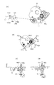
図1(a)を用いて、駆動側可動部材としての駆動側当接離間レバー70について説明する。図1(a)は駆動側当接離間レバー70、及び、周辺形状の説明図であり、現像カートリッジB1を駆動側からみた断面図である。
(7) Contact / separation lever as a movable member A drive-side contact / separation lever 70 as a drive-side movable member will be described with reference to FIG. FIG. 1A is an explanatory diagram of the driving side contact / separation lever 70 and its peripheral shape, and is a cross-sectional view of the developing cartridge B1 as viewed from the driving side.

図1(a)に示すように、駆動側当接離間レバー70は、第一当接面70a、第二当接面70b、第三当接面70c、被支持部70d、駆動側規制当接部70e、第一突出部(一端側突出部)70fを有している。そして、駆動側現像軸受36に対して、駆動側現像軸受36の支持部36cに駆動側当接離間レバー70の被支持部70dが回転可能に支持されている。具体的には、駆動側当接離間レバー70の被支持部70dの穴と駆動側現像軸受36の支持部36cのボスとが嵌合することで、駆動側当接離間レバー70は、支持部36cのボスを中心に回転可能(矢印N9、N10方向)に支持されている。つまり支持部36cは駆動側当接離間レバー70の回転中心となる。また、本実施例においては、駆動側現像軸受36の支持部36cは現像ローラ13の回転軸L0と平行である。即ち、駆動側現像当接離間レバー70は、現像ローラ13の回転軸L0と直交する平面上で回動可能である。   As shown in FIG. 1A, the drive-side contact / separation lever 70 includes a first contact surface 70a, a second contact surface 70b, a third contact surface 70c, a supported portion 70d, and a drive-side regulating contact. It has a portion 70e and a first protruding portion (one end side protruding portion) 70f. The supported portion 70d of the driving side contact / separation lever 70 is rotatably supported by the support portion 36c of the driving side developing bearing 36 with respect to the driving side developing bearing 36. Specifically, when the hole of the supported portion 70d of the drive side contact / separation lever 70 and the boss of the support portion 36c of the drive side developing bearing 36 are fitted, the drive side contact / separation lever 70 is supported by the support portion. The boss 36c is supported so as to be rotatable (in the directions of arrows N9 and N10). That is, the support portion 36 c becomes the rotation center of the drive side contact / separation lever 70. In this embodiment, the support portion 36 c of the driving side developing bearing 36 is parallel to the rotation axis L 0 of the developing roller 13. That is, the drive-side development contact / separation lever 70 can be rotated on a plane orthogonal to the rotation axis L0 of the development roller 13.

さらに、駆動側当接離間レバー70は、第三当接面70cにおいて圧縮バネである第一弾性部としての駆動側現像加圧バネ71の一端71dと当接している。駆動側現像加圧バネ71の他端71eは、駆動側現像軸受36の当接面36dと当接している。その結果、駆動側当接離間レバー70は、第三当接面70cにおいて駆動側現像加圧バネ71から矢印N16方向に力を受けていている。そして、駆動側現像加圧バネ71は駆動側当接離間レバー70の第一当接面70aが現像ローラ13から離れる方向(N16)に付勢している。現像カートリッジB1単体の状態、すなわち、現像カートリッジB1が装置本体A1に装着される前の状態では駆動側規制当接部70eが駆動側現像軸受36に設けられた規制部36bに当接している。   Further, the drive side contact / separation lever 70 is in contact with one end 71d of the drive side development pressure spring 71 as a first elastic portion which is a compression spring on the third contact surface 70c. The other end 71 e of the driving side developing pressure spring 71 is in contact with the contact surface 36 d of the driving side developing bearing 36. As a result, the driving side contact / separation lever 70 receives a force in the direction of the arrow N16 from the driving side development pressing spring 71 on the third contact surface 70c. The drive-side development pressure spring 71 is biased in a direction (N16) in which the first contact surface 70a of the drive-side contact / separation lever 70 is separated from the developing roller 13. In the state of the developing cartridge B1 alone, that is, the state before the developing cartridge B1 is attached to the apparatus main body A1, the driving side regulation abutting portion 70e abuts on the regulation portion 36b provided on the driving side developing bearing 36.

ここで、図37は、現像カートリッジB1の断面図に、駆動側当接離間レバー70を投影した図である。図37において被支持部70d(駆動側当接離間レバー70の回転中心)は、現像剤収容部16aと重なる位置(つまり現像剤収容部16aの内部)にある。つまり、現像ローラ13の回転軸L0平行な方向である矢印N11方向(図4参照)に沿って現像カートリッジB1を見ると、駆動側当接離間レバー70の被支持部70dは現像容器16の現像剤収容部16aと重なる位置にある。尚、図示はしていないが非駆動側当接離間レバー72も同様の構成なっている。   Here, FIG. 37 is a diagram in which the drive-side contact / separation lever 70 is projected onto the cross-sectional view of the developing cartridge B1. In FIG. 37, the supported portion 70d (the rotation center of the drive-side contact / separation lever 70) is located at a position overlapping the developer accommodating portion 16a (that is, inside the developer accommodating portion 16a). That is, when the developing cartridge B1 is viewed along the arrow N11 direction (see FIG. 4) that is parallel to the rotation axis L0 of the developing roller 13, the supported portion 70d of the driving side contact / separation lever 70 is developed in the developing container 16. It exists in the position which overlaps with the medicine storage part 16a. Although not shown, the non-drive side contact / separation lever 72 has the same configuration.

従って、駆動側当接離間レバー70及び非駆動側当接離間レバー72の現像剤収容部16aからの突出量を少なくでき、現像カートリッジB1の現像ローラ13の回転軸方向からみた大きさを小型化できる。   Accordingly, the amount of protrusion of the driving side contact / separation lever 70 and the non-drive side contact / separation lever 72 from the developer accommodating portion 16a can be reduced, and the size of the developing cartridge B1 viewed from the rotation axis direction of the developing roller 13 can be reduced. it can.

図1(b)を用いて、非駆動側可動部材としての非駆動側当接離間レバー72について説明する。なお、非駆動側は駆動側と類似構成である。   The non-driving side contact / separation lever 72 as a non-driving side movable member will be described with reference to FIG. The non-driving side has a similar configuration to the driving side.

図1(b)は現像カートリッジB1を非駆動側から見た側面図である。但し、非駆動側当接離間レバー72の構成説明の為に、一部部品を非表示にしている。   FIG. 1B is a side view of the developing cartridge B1 viewed from the non-driving side. However, in order to explain the configuration of the non-drive side contact / separation lever 72, some parts are not displayed.

図1(b)に示すように、非駆動側当接離間レバー72は、非駆動側第一当接面72a、非駆動側第二当接面72b、非駆動側第三当接面72c、被支持部72d、非駆動側規制当接部72e、非駆動側第一突出部(他端側突出部)72fを有している。そして、非駆動側現像軸受46の支持部46fによって、非駆動側当接離間レバー72の被支持部72dが支持されている。具体的には、非駆動側当接離間レバー72の被支持部72dの穴と非駆動側現像軸受46の支持部46fのボスとが嵌合することで、非駆動側当接離間レバー72は、支持部46fのボスを中心に回転可能(矢印NH9、NH10方向)に支持されている。つまり、支持部46fは非駆動側当接離間レバー72の回転中心である。また、本実施例においては、非駆動側現像軸受46の支持部46fは現像ローラ13の回転軸L0と平行である。即ち、非駆動側現像当接離間レバー72は、現像ローラ13の回転軸L0と直交する平面上で回動可能である。   As shown in FIG. 1B, the non-drive side contact / separation lever 72 includes a non-drive side first contact surface 72a, a non-drive side second contact surface 72b, a non-drive side third contact surface 72c, It has a supported portion 72d, a non-driving side regulating contact portion 72e, and a non-driving side first projecting portion (the other end side projecting portion) 72f. The supported portion 72 d of the non-driving side contact / separation lever 72 is supported by the support portion 46 f of the non-driving side developing bearing 46. Specifically, the non-driving side contact / separation lever 72 is formed by fitting the hole of the supported portion 72d of the non-drive side contact / separation lever 72 with the boss of the support portion 46f of the non-drive side developing bearing 46. The support portion 46f is supported so as to be rotatable (in the directions of arrows NH9 and NH10). That is, the support portion 46 f is the rotation center of the non-drive side contact / separation lever 72. In the present embodiment, the support portion 46 f of the non-drive side developing bearing 46 is parallel to the rotation axis L 0 of the developing roller 13. That is, the non-drive-side development contact / separation lever 72 is rotatable on a plane perpendicular to the rotation axis L0 of the development roller 13.

さらに、非駆動側当接離間レバー72は、非駆動側第三当接面72cにおいて圧縮バネである第二弾性部としての非駆動側現像加圧バネ73の一端73eと当接している。非駆動側現像加圧バネ73の他端73dは、非駆動側現像軸受46の当接面46gと当接している。その結果、非駆動側当接離間レバー72は、非駆動側第三当接面72cにおいて非駆動側現像加圧バネ73から矢印NH16方向に力FH10を受けている。そして、非駆動側現像加圧バネ73は非駆動側当接離間レバー72の第一当接面72aを現像ローラ13から離れる方向(矢印NH16)に付勢している。現像カートリッジB1単体の状態、すなわち、現像カートリッジB1が装置本体A1に装着される前の状態では非駆動側規制当接部72eが非駆動側現像軸受46に設けられた規制部46eに当接している。   Further, the non-drive side contact / separation lever 72 is in contact with one end 73e of the non-drive side development pressurizing spring 73 as a second elastic portion which is a compression spring on the non-drive side third contact surface 72c. The other end 73 d of the non-driving side developing pressure spring 73 is in contact with the contact surface 46 g of the non-driving side developing bearing 46. As a result, the non-drive side contact / separation lever 72 receives a force FH10 in the direction of the arrow NH16 from the non-drive side development pressure spring 73 on the non-drive side third contact surface 72c. The non-drive side development pressure spring 73 biases the first contact surface 72a of the non-drive side contact / separation lever 72 in a direction away from the developing roller 13 (arrow NH16). In the state of the developing cartridge B1 alone, that is, the state before the developing cartridge B1 is attached to the apparatus main body A1, the non-driving side regulating abutting portion 72e abuts on the regulating portion 46e provided on the non-driving side developing bearing 46. Yes.

図1に示すように、規制部36bと規制部46eは、各々駆動側現像加圧バネ71、及び非駆動側現像加圧バネ73の付勢方向で、駆動側現像加圧バネ71、及び非駆動側現像加圧バネ73と一部が重なるように構成されている。言い換えると、駆動側当接離間レバー70は、規制部36bと駆動側現像加圧バネ71とで挟み込まれて、圧縮力を受ける構成となっている。すなわち、駆動側当接離間レバー70の被離間部70gが規制部36bに当接した後の被離間部70gの位置を精度よく位置決めすることができる。また、非駆動側も同様である。結果として、後述する装置本体の離間機構による離間力を高精度なタイミングで受けることができる。   As shown in FIG. 1, the restricting portion 36 b and the restricting portion 46 e are respectively in the urging directions of the driving-side developing pressure spring 71 and the non-driving-side developing pressure spring 73, and the driving-side developing pressure spring 71 and the non-driving pressure spring 71. The driving side developing pressure spring 73 is configured to partially overlap. In other words, the drive-side contact / separation lever 70 is sandwiched between the restricting portion 36b and the drive-side development pressure spring 71 and receives a compression force. That is, it is possible to accurately position the separated portion 70g after the separated portion 70g of the driving side contact / separation lever 70 contacts the restricting portion 36b. The same applies to the non-driving side. As a result, the separation force by the separation mechanism of the apparatus main body, which will be described later, can be received at a highly accurate timing.

規制部36bと規制部46eは、各々駆動側当接離間レバー70、非駆動側当接離間レバー72が現像ローラ13から遠ざかる方向へ移動するのを規制している。言い換えると規制部36bと規制部46eは、各々駆動側当接離間レバー70、非駆動側当接離間レバー72が現像ローラ13から遠ざかる方向へ移動するのを規制できる位置に設けられている。現像ローラ13を感光ドラム10に対して離間させる際には、駆動側当接離間レバー70、および、非駆動側当接離間レバー72はそれぞれ回動方向N10及びNH10に回動させて、規制部36bと規制部46eに当接させる。これにより、装置本体の離間機構による離間力が、駆動側当接離間レバー70、および、非駆動側当接離間レバー72から規制部36bと規制部46eを介して、現像枠体の駆動側現像軸受36と非駆動側現像軸受46とへ伝達される状態となる。   The restricting portion 36 b and the restricting portion 46 e restrict the movement of the drive side contact / separation lever 70 and the non-drive side contact / separation lever 72 in a direction away from the developing roller 13. In other words, the restricting portion 36b and the restricting portion 46e are provided at positions where the drive side contact / separation lever 70 and the non-drive side contact / separation lever 72 can be restricted from moving away from the developing roller 13, respectively. When the developing roller 13 is separated from the photosensitive drum 10, the drive side contact / separation lever 70 and the non-drive side contact / separation lever 72 are rotated in the rotation directions N10 and NH10, respectively. It abuts on 36b and the control part 46e. As a result, the separation force by the separation mechanism of the apparatus main body causes the drive side development of the developing frame body from the drive side contact / separation lever 70 and the non-drive side contact / separation lever 72 via the restriction portion 36b and the restriction portion 46e. The state is transmitted to the bearing 36 and the non-driving side developing bearing 46.

図44は、規制部36b、規制部46e、駆動側当接離間レバー70、非駆動側当接離間レバー72、駆動側現像加圧バネ71、及び非駆動側現像加圧バネ73の、現像ローラ13の長手方向における位置関係を示した模式図である。図44は、現像ローラ13の長手方向(回転軸L0方向)に直交する方向から見た図である。規制部36bは、駆動側現像加圧バネ71及び駆動側第三当接面70cと、現像ローラ13の長手方向(回転軸L0方向)に平行なN11方向に関して、少なくとも一部が重なるように構成されている。同様に、規制部46eは、非駆動側現像加圧バネ73及び非駆動側第三当接面72cと、N11方向に関して、少なくとも一部が重なるように構成されている。それにより、後述する装置本体の離間機構による離間力を高精度なタイミングで受けることができる。   44 shows the developing roller of the restricting portion 36b, the restricting portion 46e, the drive side contact / separation lever 70, the non-drive side contact / separation lever 72, the drive side development pressure spring 71, and the non-drive side development pressure spring 73. 13 is a schematic diagram showing a positional relationship of 13 in the longitudinal direction. FIG. FIG. 44 is a view as seen from a direction orthogonal to the longitudinal direction of the developing roller 13 (rotation axis L0 direction). The restricting portion 36b is configured such that at least a part thereof overlaps with the driving side developing pressure spring 71 and the driving side third contact surface 70c with respect to the N11 direction parallel to the longitudinal direction of the developing roller 13 (direction of the rotation axis L0). Has been. Similarly, the restricting portion 46e is configured to at least partially overlap the non-driving side development pressing spring 73 and the non-driving side third contact surface 72c in the N11 direction. Thereby, the separation force by the separation mechanism of the apparatus main body, which will be described later, can be received at a highly accurate timing.

また、図1に示すように、矢印M2方向についても、規制部36bは、駆動側現像加圧バネ71及び駆動側第三当接面70cと少なくとも一部が重なるように構成されている。同様に、矢印M2方向について、規制部46eは、非駆動側現像加圧バネ73及び非駆動側第三当接面72cと少なくとも一部が重なるように構成されている。しかしながら、N11方向また矢印M2方向のいずれか一方向に関して、上述した規制部36b、規制部46eの配置関係となっていればよい。   Further, as shown in FIG. 1, also in the arrow M2 direction, the restricting portion 36b is configured to at least partially overlap with the driving side developing and pressing spring 71 and the driving side third contact surface 70c. Similarly, in the arrow M2 direction, the restricting portion 46e is configured to at least partially overlap the non-driving side development pressing spring 73 and the non-driving side third contact surface 72c. However, it is only necessary that the restricting portion 36b and the restricting portion 46e are arranged in any one of the N11 direction and the arrow M2 direction.

ここで、駆動側現像加圧バネ71の付勢力F10と非駆動側現像加圧バネ73の付勢力FH10は異なる設定としている。また、駆動側第三当接面70cと非駆動側第三当接面72cは異なる角度で配置されている。これは、後述する感光ドラム10に対する現像ローラ13の押圧力が適正になるように周辺構成の特性を考慮して適宜選択すれば良い。本実施例においては、現像ローラ13を回転駆動する為に、装置本体A1から駆動伝達を受けた時に現像カートリッジ13に発生するモーメントM6(図27(a)参照)の影響を考慮して、
F10<FH10
という関係で設定している。
Here, the urging force F10 of the driving-side developing pressurizing spring 71 and the urging force FH10 of the non-driving-side developing pressurizing spring 73 are set differently. Further, the drive side third contact surface 70c and the non-drive side third contact surface 72c are arranged at different angles. This may be appropriately selected in consideration of the characteristics of the peripheral configuration so that the pressing force of the developing roller 13 against the photosensitive drum 10 described later is appropriate. In this embodiment, in order to rotationally drive the developing roller 13, in consideration of the influence of the moment M6 (see FIG. 27A) generated in the developing cartridge 13 when receiving drive transmission from the apparatus main body A1,
F10 <FH10
It is set in the relationship.

つまり駆動側では、図8に示すようにカップリング部材180が矢印X6方向に回転する。その回転力を受けた現像カートリッジB1は、駆動側スイングガイド80と一体に、図27に示す矢印N6方向に支持部80g(図27参照)を中心に揺動する。カップリング部材180が本体側駆動部材100から受ける回転力(トルク)が十分にある時には、カップリング部材180のトルクだけで矢印N6方向のモーメントを生じ、現像ローラ13を感光ドラム10に対して圧接する力が発生する。その為、駆動側現像加圧バネ71の付勢力F10を非駆動側現像加圧バネ73の付勢力FH10と比べて小さくしてもいい。   That is, on the drive side, the coupling member 180 rotates in the direction of the arrow X6 as shown in FIG. The developing cartridge B1 receiving the rotational force swings around the support portion 80g (see FIG. 27) in the direction of the arrow N6 shown in FIG. When the rotational force (torque) received by the coupling member 180 from the main body side driving member 100 is sufficient, a moment in the direction of arrow N6 is generated only by the torque of the coupling member 180, and the developing roller 13 is pressed against the photosensitive drum 10. To generate power. Therefore, the urging force F10 of the driving-side developing pressurizing spring 71 may be smaller than the urging force FH10 of the non-driving-side developing pressurizing spring 73.

ここで、図1(a)に示すように、現像ローラ13の中心13zを通り、現像カートリッジB1の装置本体A1への装着方向X2(図17)と平行な直線Z30を定義する。駆動側当接離間レバー70は、直線Z30に対して感光ドラム10とは反対側に配置される(本実施例においては重力方向下側)。この構成により現像カートリッジを着脱する際に、ドラムカートリッジCとの間の配置に自由度が増す。具体的には、駆動側当接離間レバー70がドラムカートリッジC方向へ突出しない構成とすることで、ドラムカートリッジCの配置の自由度が増す。突出する駆動側当接離間レバー70等との干渉を避けた配置にする必要がない。   Here, as shown in FIG. 1A, a straight line Z30 passing through the center 13z of the developing roller 13 and parallel to the mounting direction X2 (FIG. 17) of the developing cartridge B1 to the apparatus main body A1 is defined. The driving side contact / separation lever 70 is disposed on the opposite side of the straight line Z30 from the photosensitive drum 10 (lower side in the gravitational direction in this embodiment). With this configuration, the degree of freedom in arrangement with the drum cartridge C is increased when the developing cartridge is attached and detached. Specifically, the configuration in which the drive side contact / separation lever 70 does not protrude in the direction of the drum cartridge C increases the degree of freedom of arrangement of the drum cartridge C. There is no need to make an arrangement that avoids interference with the protruding drive-side contact / separation lever 70 or the like.

そして、駆動側当接離間レバー70の第一突出部70fは長手方向(回転軸方向)に沿って現像カートリッジの駆動側からみると、現像容器16、駆動側現像軸受36、現像サイドカバー34(図10参照)より突出している。   The first projecting portion 70f of the driving side contact / separation lever 70 is viewed from the driving side of the developing cartridge along the longitudinal direction (rotating shaft direction), and the developing container 16, the driving side developing bearing 36, the developing side cover 34 ( (See FIG. 10).

つまり現像カートリッジを長手方向(回転軸L0方向)に沿って駆動側(一端側)から見た際、図11で示されるように駆動側当接離間レバー70の第一突出部(一端側突出部)70fは現像枠体(16、46、36、34)から露出している。   That is, when the developing cartridge is viewed from the driving side (one end side) along the longitudinal direction (rotation axis L0 direction), as shown in FIG. 11, the first protruding portion (one end protruding portion) of the driving side contact / separation lever 70 is shown. ) 70f is exposed from the developing device frame (16, 46, 36, 34).

しかしながら、現像カートリッジB1を長手方向(回転軸L0方向)に沿って見た際に、駆動側離間レバー70が必ずしも現像枠体(16、46、36、34)から露出している必要はない。現像カートリッジB1を駆動側や被駆動側から見たとき駆動側離間レバー70が現像枠体の陰に隠れてしまい、第一突出部70fが露出しない(見えない)構成も考えられる。   However, when the developing cartridge B1 is viewed along the longitudinal direction (the direction of the rotation axis L0), the driving side separation lever 70 does not necessarily have to be exposed from the developing frame (16, 46, 36, 34). A configuration is also conceivable in which when the developing cartridge B1 is viewed from the driving side or the driven side, the driving side separation lever 70 is hidden behind the developing frame and the first protrusion 70f is not exposed (not visible).

つまり突出部70fは、駆動側離間レバー70(特に突出部70f)を通り、長手方向(現像ローラ13の回転軸L0)に直交する現像カートリッジの断面(図1(a)参照)において、現像枠体(16、46、36、34)から突出していればよい。このような構成であれば、後述する駆動側装置押圧部材150(図27参照)が突出部70fと係合可能である。   That is, the projecting portion 70f passes through the drive side separation lever 70 (particularly the projecting portion 70f), and in the cross section of the developing cartridge (see FIG. 1A) perpendicular to the longitudinal direction (the rotation axis L0 of the developing roller 13). It only has to protrude from the body (16, 46, 36, 34). With such a configuration, a drive-side device pressing member 150 (see FIG. 27), which will be described later, can be engaged with the protrusion 70f.

言い換えると、現像ローラ13の長手方向において駆動側離間レバー70が配置された位置で、突出部70fが現像枠体から突出して現像カートリッジの外形を形成していればよい。本実施例では、突出部70fは駆動側離間レバー70が配置された位置で駆動側現像軸受36に対して突出している。仮に突出部70fが駆動側離間レバー70よりも長手方向の外側に位置する現像サイドカバー34で覆い隠されたり、駆動側離間レバー70よりも長手方向内側に位置する現像容器16で覆い隠されるような構成であってもよい。   In other words, it is only necessary that the protruding portion 70f protrudes from the developing device frame to form the outer shape of the developing cartridge at the position where the driving side separation lever 70 is disposed in the longitudinal direction of the developing roller 13. In this embodiment, the protruding portion 70f protrudes from the driving side developing bearing 36 at a position where the driving side separation lever 70 is disposed. Temporarily, the protrusion 70f is covered with the developing side cover 34 positioned on the outer side in the longitudinal direction from the driving side separating lever 70, or is covered with the developing container 16 positioned on the inner side in the longitudinal direction from the driving side separating lever 70. It may be a simple configuration.

まとめると現像ローラ13の回転軸L0方向における駆動側当接離間レバー70の位置の断面で見ると、駆動側当接離間レバー70は、現像カートリッジB1としての外形を形成するように突出している。   In summary, when viewed from the cross section of the position of the drive side contact / separation lever 70 in the direction of the rotation axis L0 of the developing roller 13, the drive side contact / separation lever 70 protrudes so as to form the outer shape of the developing cartridge B1.

さらに、第一突出部70fの突出方向(矢印M2方向)は、駆動側当接離間レバー70の可動方向(移動方向:矢印N9、N10方向)、及び現像カートリッジB1の可動方向(移動方向:矢印N6方向(図27(a)参照))に対して交差する。   Further, the projecting direction (arrow M2 direction) of the first projecting portion 70f is the movable direction of the drive side contact / separation lever 70 (moving direction: arrow N9, N10 direction) and the movable direction of the developing cartridge B1 (moving direction: arrow). Crosses the N6 direction (see FIG. 27A)).

また、第一突出部70fは、駆動側当接離間レバー70の被支持部70dから見て現像ローラ13の逆側に第一当接面70aを有している。詳細は後述するが、感光ドラム10に対して現像ローラ13を加圧する際に、駆動側装置押圧部材150の第二当接面150bと駆動側当接離間レバー70の第一当接面70aとが当接する構成となっている(図27(a)参照)。さらに、第一突出部70fの先端には、第一突出部70fの突出方向(矢印M2方向)と交差し、現像ローラ13側に突出する被離間部70gが設けられている。被離間部70gは第二当接面70bを有している。詳細は後述するが、感光ドラム10に対して現像ローラ13を離間する際には(図28参照)、駆動側装置押圧部材150の第一当接面150aと駆動側当接離間レバー70の第二当接面70bとが当接する構成となっている。   Further, the first protrusion 70 f has a first contact surface 70 a on the opposite side of the developing roller 13 when viewed from the supported portion 70 d of the drive side contact / separation lever 70. Although details will be described later, when the developing roller 13 is pressed against the photosensitive drum 10, the second contact surface 150 b of the drive-side device pressing member 150 and the first contact surface 70 a of the drive-side contact / separation lever 70 Are in contact with each other (see FIG. 27A). Furthermore, a spaced-apart portion 70g that protrudes toward the developing roller 13 is provided at the tip of the first protruding portion 70f, intersecting the protruding direction (arrow M2 direction) of the first protruding portion 70f. The separated portion 70g has a second contact surface 70b. As will be described in detail later, when the developing roller 13 is separated from the photosensitive drum 10 (see FIG. 28), the first contact surface 150a of the drive-side device pressing member 150 and the first contact-separation lever 70 of the drive-side contact / separation lever 70 are used. The two contact surfaces 70b are in contact with each other.

次に図1(b)を用いて、非駆動側当接離間レバー72の形状について詳細に説明する。前述した駆動側と同様に、非駆動側当接離間レバー72は現像ローラ13の中心13zを通り、現像カートリッジB1の装置本体A1への装着方向X2と平行な直線Z30に対して感光ドラム10とは反対側に配置される(本実施例においては重力方向下側)。この構成により現像カートリッジを着脱する際に、ドラムカートリッジCとの間の配置に自由度が増す。具体的には、非駆動側当接離間レバー72がドラムカートリッジC方向へ突出しない構成とすることで、ドラムカートリッジCの配置の自由度が増す。突出する非駆動側当接離間レバー72等との干渉を避けた配置にする必要がない。   Next, the shape of the non-driving side contact / separation lever 72 will be described in detail with reference to FIG. Similarly to the driving side described above, the non-driving side contact / separation lever 72 passes through the center 13z of the developing roller 13 and the photosensitive drum 10 with respect to the straight line Z30 parallel to the mounting direction X2 of the developing cartridge B1 to the apparatus main body A1. Are arranged on the opposite side (in the present embodiment, on the lower side in the direction of gravity). With this configuration, the degree of freedom in arrangement with the drum cartridge C is increased when the developing cartridge is attached and detached. Specifically, the non-driving side contact / separation lever 72 does not protrude in the direction of the drum cartridge C, so that the degree of freedom of arrangement of the drum cartridge C is increased. There is no need to make an arrangement avoiding interference with the protruding non-drive side contact / separation lever 72 and the like.

そして、非駆動側当接離間レバー72の第一突出部72fは長手方向からみて現像容器16、非駆動側現像軸受46より突出している。つまり現像カートリッジを長手方向(回転軸L0方向)に沿って非駆動側(他端側)から見た際、非駆動側当接離間レバー72の第一突出部(他端側突出部)72fは現像枠体(16、46、36、34)から露出している(図5参照)。   The first projecting portion 72 f of the non-driving side contact / separation lever 72 projects from the developing container 16 and the non-driving side developing bearing 46 as viewed from the longitudinal direction. That is, when the developing cartridge is viewed from the non-driving side (the other end side) along the longitudinal direction (rotation axis L0 direction), the first projecting portion (the other end projecting portion) 72f of the non-driving side contact / separation lever 72 is It is exposed from the developing frame (16, 46, 36, 34) (see FIG. 5).

ただし第一突出部72fも第一突出部70fと同様に、現像カートリッジB1を長手方向(回転軸L0方向)に沿って見た際に露出している必要はない。   However, like the first protrusion 70f, the first protrusion 72f does not need to be exposed when the developing cartridge B1 is viewed along the longitudinal direction (direction of the rotation axis L0).

つまり第一突出部72fも第一突出部70f同様に、駆動側離間レバー72を通り(特に突出部72f)、長手方向(現像ローラ13の回転軸L0)に直交する現像カートリッジの断面において、現像枠体(16、36、34)から突出していればよい。このような構成であれば、後述する非駆動側装置押圧部材151(図29参照)が突出部72fと係合可能である。   That is, like the first protrusion 70f, the first protrusion 72f passes through the drive-side separation lever 72 (particularly the protrusion 72f) and develops in the cross section of the developer cartridge perpendicular to the longitudinal direction (the rotation axis L0 of the developing roller 13). What is necessary is just to protrude from a frame (16, 36, 34). With such a configuration, a non-driving side device pressing member 151 (see FIG. 29), which will be described later, can be engaged with the protrusion 72f.

言い換えると、現像ローラ13の長手方向において駆動側離間レバー72が配置された位置で、突出部72fが現像枠体(本実施例では非駆動側サイドカバー46)から突出して現像カートリッジB1の外形を形成していればよい。駆動側離間レバー72が配置された位置よりも長手方向外側や長手方向内側において、現像枠体が第一突出部72fを覆って隠すような構成であってもよい。   In other words, at the position where the driving side separation lever 72 is disposed in the longitudinal direction of the developing roller 13, the protruding portion 72f protrudes from the developing frame (in this embodiment, the non-driving side side cover 46), thereby forming the outer shape of the developing cartridge B1. It only has to be formed. A configuration in which the developing device frame covers and hides the first protrusion 72f on the outer side in the longitudinal direction and the inner side in the longitudinal direction from the position where the driving side separation lever 72 is disposed may be employed.

まとめると、現像ローラ13の回転軸L0方向における非駆動側当接離間レバー72の位置の断面で見ると、非駆動側当接離間レバー72は、現像カートリッジB1としての外形を形成ように突出している。   In summary, when viewed from the cross section of the position of the non-driving side contact / separation lever 72 in the direction of the rotation axis L0 of the developing roller 13, the non-drive side contact / separation lever 72 protrudes to form the outer shape of the developing cartridge B1. Yes.

さらに、第一突出部72fの突出方向(矢印MH2方向)は、非駆動側当接離間レバー72の可動方向(移動方向:矢印NH9、NH10方向)、及び現像カートリッジB1の可動方向(移動方向:矢印M1方向(図27(a)))に対して交差する。また、第一突出部72fは、非駆動側当接離間レバー72の被支持部72dから見て現像ローラ13の逆側に第一当接面72aを有している。詳細は後述するが、感光ドラム10に対して現像ローラ13を加圧する際に、非駆動側装置押圧部材151の第二当接面151bと非駆動側当接離間レバー72の第一当接面72aとが当接する構成となっている(図29)。   Further, the projecting direction (arrow MH2 direction) of the first projecting portion 72f is the movable direction (moving direction: arrow NH9, NH10 direction) of the non-driving side contact / separation lever 72 and the movable direction (moving direction: move direction :). Crosses the direction of the arrow M1 (FIG. 27A). The first protrusion 72 f has a first contact surface 72 a on the opposite side of the developing roller 13 as viewed from the supported portion 72 d of the non-drive side contact / separation lever 72. As will be described in detail later, when the developing roller 13 is pressed against the photosensitive drum 10, the second contact surface 151 b of the non-drive side device pressing member 151 and the first contact surface of the non-drive side contact / separation lever 72. 72a abuts the structure (FIG. 29).

さらに、第一突出部72fの先端には、第一突出部72fの現像容器16からの突出方向(矢印MH2方向)と交差し、現像ローラ13側に突出する被離間部72gが設けられている。被離間部72gは第二当接面72bを有している。詳細は後述するが、感光ドラム10に対して現像ローラ13を離間する際には(図29参照)、非駆動側装置押圧部材151の第一当接面151aと非駆動側当接離間レバー72の第二当接面72bとが当接する構成となっている。   Further, a spaced-apart portion 72g that protrudes toward the developing roller 13 is provided at the tip of the first protruding portion 72f so as to intersect the protruding direction (arrow MH2 direction) of the first protruding portion 72f from the developing container 16. . The separated portion 72g has a second contact surface 72b. As will be described in detail later, when the developing roller 13 is separated from the photosensitive drum 10 (see FIG. 29), the first contact surface 151a of the non-drive side device pressing member 151 and the non-drive side contact / separation lever 72 are used. The second contact surface 72b is in contact with the second contact surface 72b.

また、駆動側当接離間レバー70と非駆動側当接離間レバー72は、前述のように、現像ローラ13の軸線方向(長手方向)に対して、現像カートリッジの両端に設けられている。また、画像形成に用いる記録紙、ラベル紙、OHPシート等のメディア幅よりも外側に駆動側当接離間レバー70と非駆動側当接離間レバー72を配置することもできる。この場合、長手方向を法線とする平面で装置本体を見たときに、駆動側当接離間レバー70等とメディア、および、メディアを搬送する装置本体に設けられた搬送部材等とを交差した位置に配置することもできる。結果として、装置本体の小型化を図ることもできる。   Further, the drive side contact / separation lever 70 and the non-drive side contact / separation lever 72 are provided at both ends of the developing cartridge with respect to the axial direction (longitudinal direction) of the developing roller 13 as described above. In addition, the driving side contact / separation lever 70 and the non-drive side contact / separation lever 72 can be disposed outside the media width of recording paper, label paper, OHP sheet, and the like used for image formation. In this case, when the apparatus main body is viewed in a plane whose normal is the longitudinal direction, the drive-side contact / separation lever 70 and the like intersect with the medium and the conveyance member provided on the apparatus main body for conveying the medium. It can also be placed in position. As a result, the apparatus main body can be reduced in size.

次に、図24を用いて、駆動側当接離間レバー70と非駆動側当接離間レバー72の配置について詳細に説明する。図24は現像カートリッジB1を現像ローラ13側から見た正面図である。但し、現像ローラ13の駆動側被支持部13aを支持する駆動側現像軸受36の支持部36aと、現像ローラ13の非駆動側被支持部13cを支持する非駆動側現像軸受46の支持部46f付近を断面図としている。   Next, the arrangement of the drive side contact / separation lever 70 and the non-drive side contact / separation lever 72 will be described in detail with reference to FIG. FIG. 24 is a front view of the developing cartridge B1 as viewed from the developing roller 13 side. However, a support portion 36a of the driving side developing bearing 36 that supports the driving side supported portion 13a of the developing roller 13 and a supporting portion 46f of the non-driving side developing bearing 46 that supports the non-driving side supported portion 13c of the developing roller 13. The vicinity is a cross-sectional view.

前述した通り、駆動側当接離間レバー70は、現像カートリッジB1の長手方向において、駆動側端部に設けられている。また、非駆動側当接離間レバー72は、現像カートリッジB1の長手方向において、非駆動側端部に設けられている。そして、駆動側当接離間レバー70と非駆動側当接離間レバー72の回動動作(図1(a)矢印N9、N10方向、及び図1(b)矢印NH9、NH10方向)は、互いに影響を与えること無く独立して回動可能である。   As described above, the drive side contact / separation lever 70 is provided at the drive side end in the longitudinal direction of the developing cartridge B1. The non-drive side contact / separation lever 72 is provided at the non-drive side end in the longitudinal direction of the developing cartridge B1. The rotational movements of the drive side contact / separation lever 70 and the non-drive side contact / separation lever 72 (the directions of arrows N9 and N10 in FIG. 1A and the directions of arrows NH9 and NH10 in FIG. 1B) affect each other. It is possible to rotate independently without giving.

ここで、長手方向において、現像ローラ13の駆動側被支持部13aは、画像形成範囲L13bの駆動側端部L13bkよりも長手外側で駆動側現像軸受36の支持部36aに支持されている。さらに、現像ローラ13の非駆動側被支持部13cは、画像形成範囲L13bの非駆動側端部L13bhよりも長手外側で非駆動側現像軸受46の支持部46fに支持されている。そして、駆動側当接離間レバー70と非駆動側当接離間レバー72は現像ローラ13の全長L13aの範囲と少なくとも一部が重なり合って配置されている。さらに、現像ローラ13の画像形成範囲L13bよりも外側に配置されている。   Here, in the longitudinal direction, the driving-side supported portion 13a of the developing roller 13 is supported by the supporting portion 36a of the driving-side developing bearing 36 on the outer side of the driving side end L13bk in the image forming range L13b. Further, the non-driving side supported portion 13c of the developing roller 13 is supported by the supporting portion 46f of the non-driving side developing bearing 46 on the outer side of the non-driving side end portion L13bh of the image forming range L13b. The drive-side contact / separation lever 70 and the non-drive-side contact / separation lever 72 are arranged so that at least a part thereof overlaps the range of the entire length L13a of the developing roller 13. Further, it is disposed outside the image forming range L13b of the developing roller 13.

即ち、駆動側当接離間レバー70と現像ローラ13の駆動側被支持部13aは、画像形成領域L13bの駆動側端部L13bkと現像ローラ13の全長L13aの駆動側端部L13akに挟まれた領域L14kと少なくとも一部が重なるように配置されている。その為、駆動側当接離間レバー70と現像ローラ13の駆動側被支持部13aは、長手方向において近接した位置に配置となる。   That is, the driving side contact / separation lever 70 and the driving side supported portion 13a of the developing roller 13 are sandwiched between the driving side end L13bk of the image forming region L13b and the driving side end L13ak of the entire length L13a of the developing roller 13. It arrange | positions so that L14k and at least one part may overlap. For this reason, the driving side contact / separation lever 70 and the driving side supported portion 13a of the developing roller 13 are arranged at positions close to each other in the longitudinal direction.

また、非駆動側当接離間レバー72と現像ローラ13の非駆動側被支持部13cは、画像形成領域L13bの非駆動側端部L13bhと現像ローラ13の全長L13aの非駆動側端部L13ahに挟まれた領域L14hと少なくとも一部が重なる。この関係を満たすように、非駆動側当接離間レバー72と現像ローラ13の被駆動側被支持部13cが配置されている。その為、非駆動側当接離間レバー72と現像ローラ13の駆動側被支持部13cは、長手方向において近接した位置に配置となる。(当接離間構成の説明)   Further, the non-driving side contact / separation lever 72 and the non-driving side supported portion 13c of the developing roller 13 are located on the non-driving side end L13bh of the image forming region L13b and the non-driving side end L13ah of the entire length L13a of the developing roller 13. At least a part of the sandwiched region L14h overlaps. A non-driving side contact / separation lever 72 and a driven side supported portion 13c of the developing roller 13 are arranged so as to satisfy this relationship. Therefore, the non-driving side contact / separation lever 72 and the driving side supported portion 13c of the developing roller 13 are arranged at positions close to each other in the longitudinal direction. (Description of contact / separation configuration)

(装置本体の現像加圧、及び、現像離間構成)
次に、装置本体の現像加圧、及び、現像離間構成について説明する。
(Development pressure and development separation structure of the device body)
Next, the development pressurization and development separation structure of the apparatus main body will be described.

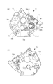
図25(a)は、装置本体A1の駆動側側板90を非駆動側から見た分解斜視図、図25(b)は非駆動側から見た側面図である。図26(a)は、装置本体A1の非駆動側側板91を駆動側から見た分解斜視図、図26(b)は駆動側から見た側面図である。   FIG. 25A is an exploded perspective view of the driving side plate 90 of the apparatus main body A1 as viewed from the non-driving side, and FIG. 25B is a side view of the apparatus main body A1 as viewed from the non-driving side. FIG. 26A is an exploded perspective view of the non-drive side plate 91 of the apparatus main body A1 as viewed from the drive side, and FIG. 26B is a side view of the apparatus main body A1 as viewed from the drive side.

図25に示すように、装置本体A1には、現像カートリッジB1を装置本体A1に着脱するための駆動側ガイド部材92、駆動側スイングガイド80が設けられている。この駆動側ガイド部材92と駆動側スイングガイド80は、現像カートリッジB1が装置本体内に装着される際に、現像カートリッジB1の駆動側被ガイド部34dをガイドする(図18参照)。   As shown in FIG. 25, the apparatus main body A1 is provided with a driving side guide member 92 and a driving side swing guide 80 for attaching and detaching the developing cartridge B1 to and from the apparatus main body A1. The driving side guide member 92 and the driving side swing guide 80 guide the driving side guided portion 34d of the developing cartridge B1 when the developing cartridge B1 is mounted in the apparatus main body (see FIG. 18).

図25(a)に示すように、駆動側ガイド部材92は、駆動側ガイド部材92から突出したボス形状の被位置決め部92d、及び、被回転規制部92eが、駆動側側板90に設けられた穴形状の位置決め部90a、及び、回転規制部90bにそれぞれ支持される。そして、ビス(不図示)等の固定手段により駆動側ガイド部材92を駆動側側板90に位置決め固定する。また、駆動側スイングガイド80は、円筒形状の被支持凸部80gが、駆動側側板90にもけられた穴形状の支持部90cと嵌合することによって支持される。よって、駆動側スイングガイド80は駆動側側板90に対して、矢印N5方向、及び矢印N6方向に回動可能に支持される。   As shown in FIG. 25A, the driving side guide member 92 is provided with a boss-shaped positioned portion 92d protruding from the driving side guide member 92 and a rotation restricted portion 92e on the driving side plate 90. It is supported by the hole-shaped positioning part 90a and the rotation restricting part 90b, respectively. Then, the driving side guide member 92 is positioned and fixed to the driving side plate 90 by fixing means such as screws (not shown). The drive-side swing guide 80 is supported by fitting a cylindrical supported convex portion 80g with a hole-shaped support portion 90c provided on the drive-side plate 90. Therefore, the drive side swing guide 80 is supported so as to be rotatable with respect to the drive side plate 90 in the directions indicated by the arrows N5 and N6.

なお、上述の説明では、駆動側側板90に設けられた支持部90cは穴形状(凹形状)とし、一方、駆動側スイングガイド80に設けられた被支持凸部80gは凸形状の場合での説明であるが、凹凸関係はこの限りではなく、凹凸関係を逆に構成しても良い。   In the above description, the support portion 90c provided on the driving side plate 90 has a hole shape (concave shape), while the supported convex portion 80g provided on the driving side swing guide 80 has a convex shape. Although it is explanation, the concavo-convex relationship is not limited to this, and the concavo-convex relationship may be reversed.

さらに、駆動側スイングガイド80の突起部80hと駆動側側板90の突起部90dとの間には引っ張りバネである駆動側付勢手段76が設けられている。駆動側スイングガイド80は、駆動側付勢手段76によって、駆動側スイングガイド80の突起部80hと駆動側側板90の突起部90dとを近づける矢印N6方向に付勢される。 また、装置本体A1には、感光ドラム10の表面と現像ローラ13とを接触させる、及び、前記両者を離間させるための駆動側装置押圧部材150が設けられている。駆動側装置押圧部材150は、矢印N7方向、及び、矢印N8方向に移動可能な状態で底板(不図示)に支持される。   Further, drive side urging means 76 that is a tension spring is provided between the protrusion 80 h of the drive side swing guide 80 and the protrusion 90 d of the drive side plate 90. The drive-side swing guide 80 is urged by the drive-side urging means 76 in the direction of the arrow N6 that brings the protrusion 80h of the drive-side swing guide 80 and the protrusion 90d of the drive-side plate 90 close to each other. Further, the apparatus main body A1 is provided with a drive side apparatus pressing member 150 for bringing the surface of the photosensitive drum 10 and the developing roller 13 into contact with each other and separating the both. The drive-side device pressing member 150 is supported by a bottom plate (not shown) in a state that it can move in the directions indicated by arrows N7 and N8.

一方、図26に示すように、装置本体A1には、現像カートリッジB1を装置本体A1に着脱するための非駆動側ガイド部材93、非駆動側スイングガイド81が設けられている。この非駆動側ガイド部材93と非駆動側スイングガイド81は、現像カートリッジB1が装置本体内に装着される際に、現像カートリッジB1の非駆動側被ガイド部46dとガイドする(図18参照)。   On the other hand, as shown in FIG. 26, the apparatus main body A1 is provided with a non-drive side guide member 93 and a non-drive side swing guide 81 for attaching / detaching the developing cartridge B1 to / from the apparatus main body A1. The non-driving side guide member 93 and the non-driving side swing guide 81 guide the non-driving side guided portion 46d of the developing cartridge B1 when the developing cartridge B1 is mounted in the apparatus main body (see FIG. 18).

図26(a)に示すように、非駆動側ガイド部材93は、非駆動側ガイド部材93から突出したボス形状の被位置決め部93d、及び、被回転規制部93eを有する。被位置決め部93d、及び、被回転規制部93eは、非駆動側側板91に設けられた穴形状の位置決め部91a、及び、回転規制部91bにそれぞれ支持される。そして、ビス(不図示)等の固定手段により非駆動側ガイド部材93を非駆動側側板91に位置決め固定する。また、非駆動側スイングガイド81は円筒形状の被支持凸部81gが、非駆動側側板91に設けられた穴形状の支持部91cに嵌合することによって支持される。よって、非駆動側スイングガイド81は非駆動側側板91に対して、矢印N5方向、及び、矢印N6方向へ回動可能に支持される。   As shown in FIG. 26A, the non-driving side guide member 93 includes a boss-shaped positioned portion 93d and a rotation restricting portion 93e protruding from the non-driving side guide member 93. The to-be-positioned portion 93d and the to-be-rotated restricting portion 93e are supported by a hole-shaped positioning portion 91a and a rotation restricting portion 91b provided on the non-driving side plate 91, respectively. Then, the non-driving side guide member 93 is positioned and fixed to the non-driving side plate 91 by fixing means such as screws (not shown). The non-driving side swing guide 81 is supported by fitting a cylindrical supported convex portion 81g to a hole-shaped supporting portion 91c provided on the non-driving side plate 91. Therefore, the non-driving side swing guide 81 is supported so as to be rotatable with respect to the non-driving side plate 91 in the directions indicated by arrows N5 and N6.

なお、上述の説明では、非駆動側側板91に設けられた支持部91cは穴形状(凹形状)とし、一方、非駆動側スイングガイド81に設けられた被支持凸部81gは凸形状の場合での説明であるが、凹凸関係はこの限りではなく、凹凸関係を逆に構成しても良い。   In the above description, the support portion 91c provided on the non-driving side plate 91 has a hole shape (concave shape), while the supported convex portion 81g provided on the non-drive side swing guide 81 has a convex shape. However, the uneven relationship is not limited to this, and the uneven relationship may be reversed.

さらに、非駆動側スイングガイド81の突起部81hと非駆動側側板91の突起部91dとの間には引っ張りバネである非駆動側付勢手段77が設けられている。非駆動側スイングガイド81は、非駆動側付勢手段77によって、非駆動側スイングガイド81の突起部81hと非駆動側ガイド部材91の突起部91dとを近づける矢印N6方向に付勢される。   Further, non-driving side urging means 77 that is a tension spring is provided between the protrusion 81 h of the non-drive side swing guide 81 and the protrusion 91 d of the non-drive side plate 91. The non-drive side swing guide 81 is urged by the non-drive side urging means 77 in the direction of arrow N6 that brings the projection 81h of the non-drive side swing guide 81 and the projection 91d of the non-drive side guide member 91 closer.

また、駆動側と同様に、装置本体A1には、感光ドラム10の表面と現像ローラ13の接触させる、及び、前記両者を離間させるための非駆動側装置押圧部材151が設けられている。非駆動側装置押圧部材151は、矢印N7方向、及び、矢印N8方向に移動可能な状態で底板(不図示)に支持される。 (感光ドラム対する現像加圧及び現像離間)
次に、感光ドラム10に対する現像ローラ13の加圧、及び、離間について説明する。
Similarly to the driving side, the apparatus main body A1 is provided with a non-driving side apparatus pressing member 151 for bringing the surface of the photosensitive drum 10 into contact with the developing roller 13 and separating the both. The non-driving side device pressing member 151 is supported by a bottom plate (not shown) so as to be movable in the directions indicated by arrows N7 and N8. (Development pressure and development separation for photosensitive drum)
Next, pressurization and separation of the developing roller 13 with respect to the photosensitive drum 10 will be described.

<加圧機構>
以下に、現像ローラ13の構成について説明する。
<Pressure mechanism>
Hereinafter, the configuration of the developing roller 13 will be described.

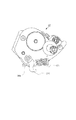
図27(a)は、駆動側スイングガイド80に支持された現像カートリッジB1に備える現像ローラ13が、感光ドラム10に当接した状態を示した側面図である。また、図27(c)は、図27(a)の駆動側当接離間レバー70周辺の詳細図であり、説明の為に駆動側スイングガイド80、及び現像サイドカバー34を非表示にしている。   FIG. 27A is a side view showing a state where the developing roller 13 provided in the developing cartridge B1 supported by the driving side swing guide 80 is in contact with the photosensitive drum 10. FIG. FIG. 27C is a detailed view of the periphery of the drive-side contact / separation lever 70 in FIG. 27A, and the drive-side swing guide 80 and the development side cover 34 are not displayed for the sake of explanation. .

本実施例では、表面に現像剤tを担持した現像ローラ13を感光ドラム10に直接接触させることで感光ドラム10上の静電潜像を現像する、いわゆる接触現像方式を用いる。   In this embodiment, a so-called contact development method is used in which an electrostatic latent image on the photosensitive drum 10 is developed by bringing the developing roller 13 carrying the developer t on the surface thereof into direct contact with the photosensitive drum 10.

現像ローラ13は、軸部13eとゴム部13dから構成される。軸部13eは、アルミ等の導電性の細長い円筒状であり、その長手方向で中央部はゴム部13dで覆われている(図6参照)。ここで、ゴム部13dは、外形形状が軸部13eと同軸線上になるように軸部13eに被覆されている。そして、軸部13eの円筒内にはマグネットローラ12が内蔵されている。ゴム部13dは、周面に現像剤tを担持し、軸部13eにバイアスを印加する。そして、現像剤tを担持した状態のゴム部13dを感光ドラム10の表面と接触させることによって、感光ドラム10上の静電潜像を現像する。   The developing roller 13 includes a shaft portion 13e and a rubber portion 13d. The shaft portion 13e has a conductive elongated cylindrical shape such as aluminum, and a central portion thereof is covered with a rubber portion 13d in the longitudinal direction (see FIG. 6). Here, the rubber portion 13d is covered with the shaft portion 13e so that the outer shape is coaxial with the shaft portion 13e. A magnet roller 12 is built in the cylinder of the shaft portion 13e. The rubber portion 13d carries the developer t on the peripheral surface and applies a bias to the shaft portion 13e. Then, the electrostatic latent image on the photosensitive drum 10 is developed by bringing the rubber portion 13 d carrying the developer t into contact with the surface of the photosensitive drum 10.

次に現像ローラ13と感光ドラム10を所定の接触圧で圧接させる機構について説明する。   Next, a mechanism for pressing the developing roller 13 and the photosensitive drum 10 with a predetermined contact pressure will be described.

前述した通り、駆動側スイングガイド80は駆動側側板90に対して矢印N5、及び、矢印N6方向に揺動可能に支持されている。また、非駆動側スイングガイド81は非駆動側側板91に対して、矢印N5、及び、矢印N6方向に揺動可能に支持されている。そして、前述のように、現像カートリッジB1は駆動側スイングガイド80、及び、非駆動側スイングガイド81に対して位置決めされている。従って、現像カートリッジB1は装置本体A1内で矢印N5、及び、矢印N6方向に揺動可能な状態にある(図29参照)。   As described above, the drive side swing guide 80 is supported to be swingable in the directions of the arrows N5 and N6 with respect to the drive side plate 90. The non-drive side swing guide 81 is supported so as to be swingable in the directions of arrows N5 and N6 with respect to the non-drive side plate 91. As described above, the developing cartridge B <b> 1 is positioned with respect to the driving side swing guide 80 and the non-driving side swing guide 81. Accordingly, the developing cartridge B1 can be swung in the directions of the arrows N5 and N6 in the apparatus main body A1 (see FIG. 29).

その状態において、図27(a)、及び図27(c)に示すように駆動側装置押圧部材150の第二当接面150bと駆動側当接離間レバー70の第一当接面70aが当接している。それにより駆動側当接離間レバー70が駆動側現像加圧バネ71の付勢力に抗して図27(c)の矢印N9方向に回転した状態となる。そして、駆動側当接離間レバー70の第三当接面70cは、駆動側現像加圧バネ71を圧縮し、駆動側現像加圧バネ71から付勢力F10aを受ける。その結果、駆動側当接離間レバー70には矢印N10方向のモーメントM10が作用する。この時、駆動側装置押圧部材150の第二当接面150bと駆動側当接離間レバー70の第一当接面70aが当接している。この為、モーメントM10と釣り合うモーメントが駆動側当接離間レバー70に作用するように、駆動側当接離間レバー70の第一当接面70aは駆動側装置押圧部材150の第二当接面150bから力F11を受ける。従って、現像カートリッジB1には力F11の外力が作用していることになる。また、前述の通り、駆動側スイングガイド80の突起部80hと駆動側側板90の突起部90dとの間には駆動側付勢手段76が設けられており、矢印N12方向に付勢される。従って、駆動側スイングガイド80に位置決めされている現像カートリッジB1には矢印N12の方向に力F12の外力が作用していることになる。   In this state, as shown in FIGS. 27A and 27C, the second contact surface 150b of the drive-side device pressing member 150 and the first contact surface 70a of the drive-side contact / separation lever 70 are in contact with each other. It touches. As a result, the drive-side contact / separation lever 70 is rotated in the direction of arrow N9 in FIG. 27C against the urging force of the drive-side developing pressure spring 71. The third contact surface 70 c of the drive side contact / separation lever 70 compresses the drive side development pressurizing spring 71 and receives an urging force F <b> 10 a from the drive side development pressurization spring 71. As a result, the moment M10 in the direction of the arrow N10 acts on the drive side contact / separation lever 70. At this time, the second contact surface 150b of the drive side device pressing member 150 and the first contact surface 70a of the drive side contact / separation lever 70 are in contact. Therefore, the first contact surface 70a of the drive side contact / separation lever 70 is the second contact surface 150b of the drive side device pressing member 150 so that a moment that balances the moment M10 acts on the drive side contact / separation lever 70. Receives force F11. Accordingly, an external force F11 is applied to the developing cartridge B1. Further, as described above, the driving side urging means 76 is provided between the protrusion 80h of the driving side swing guide 80 and the protrusion 90d of the driving side plate 90, and is urged in the direction of the arrow N12. Therefore, the external force of the force F12 is applied to the developing cartridge B1 positioned on the driving side swing guide 80 in the direction of the arrow N12.

すなわち、現像カートリッジB1は駆動側現像加圧バネ71による力F11と駆動側付勢手段76による力F12によって、現像ローラ13と感光ドラム10が近づく方向(矢印N6方向)のモーメントM6を受ける。このモーメントM6によって、現像ローラ13の弾性層13dを感光ドラム10に所定の圧で圧接可能である。   That is, the developing cartridge B1 receives a moment M6 in the direction in which the developing roller 13 and the photosensitive drum 10 approach (in the direction of arrow N6) due to the force F11 generated by the driving-side developing pressure spring 71 and the force F12 generated by the driving-side urging means 76. By this moment M6, the elastic layer 13d of the developing roller 13 can be pressed against the photosensitive drum 10 with a predetermined pressure.

次に、図29(a)は、非駆動側スイングガイド81に支持された現像カートリッジB1に備える現像ローラ13が、感光ドラム10に当接した状態を示した側面図である。また、図29(c)は、図29(a)の駆動側当接離間レバー72周辺の詳細図であり、説明の為に非駆動側スイングガイド81、及び非駆動側現像軸受46の一部を非表示にしている。   Next, FIG. 29A is a side view showing a state in which the developing roller 13 provided in the developing cartridge B1 supported by the non-drive side swing guide 81 is in contact with the photosensitive drum 10. FIG. FIG. 29C is a detailed view of the periphery of the drive side abutment / separation lever 72 of FIG. 29A, and a part of the non-drive side swing guide 81 and a part of the non-drive side developing bearing 46 for explanation. Is hidden.

非駆動側も駆動側と同様の構成であり、図29(a)、及び図29(c)に示すように、非駆動側現像加圧バネ73と非駆動側付勢手段77によって現像カートリッジB1に外力FH11、FH12が作用する。それにより、現像カートリッジB1が現像ローラ13と感光ドラム10が近づく方向(矢印N6方向)のモーメント(M6)を受け、現像ローラ13の弾性層13dを感光ドラム10に所定の圧で圧接可能でとなる。   The non-driving side has the same configuration as that of the driving side. As shown in FIGS. 29A and 29C, the developing cartridge B1 is constituted by the non-driving side developing pressure spring 73 and the non-driving side urging means 77. External forces FH11 and FH12 act on the. As a result, the developing cartridge B1 receives a moment (M6) in the direction in which the developing roller 13 and the photosensitive drum 10 approach (arrow N6 direction), and the elastic layer 13d of the developing roller 13 can be pressed against the photosensitive drum 10 with a predetermined pressure. Become.

ここで、図27(b)に示すように、現像ローラ13の回転軸線の方向から見た時の、被支持部70dの中心から第三当接面70cの中心までの距離をD10とする。同様に、被支持部70dの中心から第一当接面70aの駆動側装置押圧部材150に押圧される部分までの距離をD11とする。そして、距離D10と距離D11の関係は、
D10<D11
となる。
Here, as shown in FIG. 27B, the distance from the center of the supported portion 70d to the center of the third contact surface 70c when viewed from the direction of the rotation axis of the developing roller 13 is D10. Similarly, the distance from the center of the supported portion 70d to the portion of the first contact surface 70a that is pressed by the drive-side device pressing member 150 is D11. And the relationship between the distance D10 and the distance D11 is
D10 <D11
It becomes.

従って、駆動側現像加圧バネ71の一端71dと当接する駆動側当接離間レバー70の第三当接面70cは、突出方向M2の方向において、駆動側当接離間レバー70の被支持部70dと第一当接面70aの間に配置される。即ち、被支持部70dから第三当接面70cまでの距離W10と被支持部70dから第一当接面70aまでの距離W11の関係は、
W10<W11
となる。
Accordingly, the third contact surface 70c of the drive side contact / separation lever 70 that contacts the one end 71d of the drive side development pressure spring 71 is supported by the supported portion 70d of the drive side contact / separation lever 70 in the protruding direction M2. And the first contact surface 70a. That is, the relationship between the distance W10 from the supported portion 70d to the third contact surface 70c and the distance W11 from the supported portion 70d to the first contact surface 70a is:
W10 <W11
It becomes.

故に、第一当接面70aの移動量をW12とした場合の第3当接面70cの移動量W13の関係は、
W13<W12
ここで、W13=W12×(W10/W11)
である。
Therefore, when the movement amount of the first contact surface 70a is W12, the relationship of the movement amount W13 of the third contact surface 70c is:
W13 <W12
Here, W13 = W12 × (W10 / W11)
It is.

その為、駆動側装置押圧部材150の位置精度に誤差が発生した場合でも、駆動側現像加圧バネ71の圧縮量の変化は駆動側装置押圧部材150の位置精度の誤差よりも小さくなる。その結果、感光ドラム10に対して現像ローラ13を圧接させる為の押圧力の精度を向上することができる。非駆動側も同様の構成なので、同様の効果を得られる。   For this reason, even when an error occurs in the positional accuracy of the driving side device pressing member 150, the change in the compression amount of the driving side developing pressure spring 71 is smaller than the positional accuracy error of the driving side device pressing member 150. As a result, it is possible to improve the accuracy of the pressing force for pressing the developing roller 13 against the photosensitive drum 10. Since the non-driving side has the same configuration, the same effect can be obtained.

また、前述の通り、長手方向において、駆動側当接離間レバー70と非駆動側当接離間レバー72は現像ローラ13の全長L13aの範囲と少なくとも重なり合って配置されている(図24参照)。その為、駆動側当接離間レバー70、及び非駆動側離間レバー72の第一当接面70a、及び72aと、現像ローラ13の駆動側被支持部13a、及び非駆動側被支持部13cとの長手方向の位置差を小さくできる。駆動側当接離間レバー70は外力F11(図27(a)参照)を受けるものであり、非駆動側離間レバー72は外力FH11(図29参照)を受けるものである。そして上記位置差を小さくした結果、駆動側現像軸受36、及び非駆動側現像軸受46に作用するモーメントを抑制できる。その為、効率良く現像ローラ13を感光ドラムに圧接することができる。   Further, as described above, in the longitudinal direction, the drive side contact / separation lever 70 and the non-drive side contact / separation lever 72 are disposed so as to at least overlap the range of the entire length L13a of the developing roller 13 (see FIG. 24). Therefore, the first contact surfaces 70a and 72a of the drive side contact / separation lever 70 and the non-drive side separation lever 72, the drive side supported portion 13a, and the non-drive side supported portion 13c of the developing roller 13 The positional difference in the longitudinal direction can be reduced. The drive side contact / separation lever 70 receives an external force F11 (see FIG. 27A), and the non-drive side separation lever 72 receives an external force FH11 (see FIG. 29). As a result of reducing the positional difference, the moment acting on the driving side developing bearing 36 and the non-driving side developing bearing 46 can be suppressed. Therefore, the developing roller 13 can be efficiently pressed against the photosensitive drum.

また、前述の通り、駆動側当接離間レバー70と非駆動側当接離間レバー72の回動動作(図27(a) 矢印N9、N10方向、及び図29 矢印NH9、NH10方向)は、互いに独立して回動可能である。その為、感光ドラム10に対して現像ローラ13が圧接状態のとき、駆動側装置押圧部材150の矢印N7、N8方向(図25参照)の位置と、非駆動側装置押圧部材151の矢印N7、N8方向の位置(図26参照)をそれぞれ独立して設定することができる。さらに、駆動側当接離間レバー70と非駆動側当接離間レバー72の回動方向(図27(a) 矢印N9、N10方向、及び図29 矢印NH9、NH10方向)を一致させる必要も無い。その結果、駆動側、及び非駆動側の現像ローラ13を感光ドラム10に圧接する為の押圧力F11、FH11の大きさ、及び方向をそれぞれ適正化できる。さらに、駆動側装置押圧部材150と非駆動側装置押圧部材151の位置に相対誤差がある場合でも、互いの押圧力F11、FH11に影響し合わない。その結果、感光ドラム10に対する現像ローラ13の接圧を高精度化できる。   Further, as described above, the rotational movements of the drive side contact / separation lever 70 and the non-drive side contact / separation lever 72 (FIG. 27 (a), arrows N9 and N10 directions, and FIG. 29 arrows NH9 and NH10 directions) It can be rotated independently. Therefore, when the developing roller 13 is in pressure contact with the photosensitive drum 10, the position of the driving device pressing member 150 in the directions of arrows N7 and N8 (see FIG. 25) and the arrow N7 of the non-driving device pressing member 151, The position in the N8 direction (see FIG. 26) can be set independently. Further, it is not necessary to match the rotation directions of the drive side contact / separation lever 70 and the non-drive side contact / separation lever 72 (directions N9 and N10 in FIG. 27A and directions NH9 and NH10 in FIG. 29). As a result, the magnitudes and directions of the pressing forces F11 and FH11 for pressing the driving side and non-driving side developing rollers 13 against the photosensitive drum 10 can be optimized. Furthermore, even if there is a relative error between the positions of the driving side device pressing member 150 and the non-driving side device pressing member 151, the pressing forces F11 and FH11 are not affected. As a result, the contact pressure of the developing roller 13 with respect to the photosensitive drum 10 can be improved.

なお、感光体ドラム10と現像ローラ13とが接触して感光ドラム10上の静電潜像を現像できる状態の現像カートリッジB1の位置を当接位置と称す。一方、感光体ドラム10と現像ローラ13とが離間した状態の現像カートリッジB1の位置を離間位置と称す。現像カートリッジB1は、後述する機構により、現像カートリッジB1は当接位置と離間位置とを選択することができる構成となっている。   The position of the developing cartridge B1 in a state where the photosensitive drum 10 and the developing roller 13 are in contact with each other and the electrostatic latent image on the photosensitive drum 10 can be developed is referred to as a contact position. On the other hand, the position of the developing cartridge B1 in a state where the photosensitive drum 10 and the developing roller 13 are separated is referred to as a separated position. The developing cartridge B1 is configured such that the developing cartridge B1 can select a contact position and a separation position by a mechanism described later.

<加圧機構による現像カートリッジと装置本体の電気接続の構成>
次に、現像カートリッジB1と装置本体A1の電気接続の構成について図38を用いて説明する。現像カートリッジB1が前述の当接位置にあるとき、現像カートリッジB1におけるメモリ基板47の電極部47aと装置本体A1の給電接点120Aが接触している。ここで、給電接点120Aはばね性を有しているため、図39に示したように現像カートリッジB1装着前の形状120Aaから、電極部47aによって所定量押し込まれている。これにより、給電接点120Aは現像カートリッジB1に現像ローラ13と感光ドラム10が離れる方向の接点圧FH13を及ぼしている。一方で、図38に示したように、現像カートリッジB1には現像ローラ13と感光ドラム10を近づける方向の力FH11が作用している。このとき、図38(a)に示したように、非駆動側当接離間レバー72は、非駆動側現像軸受46の当接面46eに当接した第一位置から、非駆動側装置部材151によって突出部72fが現像ローラ13に近づいた第二位置へ押し込まれている。また、電極部47aは第一位置から第二位置への移動方向Wの下流側にあり、移動方向Wと電極部47aの表面(露出面)は交差している。
<Configuration of electrical connection between developing cartridge and main body of pressurizing mechanism>
Next, a configuration of electrical connection between the developing cartridge B1 and the apparatus main body A1 will be described with reference to FIG. When the developing cartridge B1 is in the above-described contact position, the electrode portion 47a of the memory substrate 47 and the power supply contact 120A of the apparatus main body A1 are in contact with each other in the developing cartridge B1. Here, since the power supply contact 120A has a spring property, as shown in FIG. 39, a predetermined amount is pushed by the electrode portion 47a from the shape 120Aa before the developing cartridge B1 is mounted. Accordingly, the power supply contact 120A exerts a contact pressure FH13 in the direction in which the developing roller 13 and the photosensitive drum 10 are separated from each other on the developing cartridge B1. On the other hand, as shown in FIG. 38, a force FH11 is applied to the developing cartridge B1 in a direction in which the developing roller 13 and the photosensitive drum 10 are brought close to each other. At this time, as shown in FIG. 38A, the non-driving side contact / separation lever 72 is moved from the first position in contact with the contact surface 46e of the non-driving side developing bearing 46 to the non-driving side device member 151. Thus, the projecting portion 72 f is pushed into the second position approaching the developing roller 13. Moreover, the electrode part 47a exists in the downstream of the moving direction W from a 1st position to a 2nd position, and the moving direction W and the surface (exposed surface) of the electrode part 47a cross | intersect.

従って、非駆動側当接離間レバー72を方向Wへ移動させる力FH11と、接点圧FH13と、が各々対向する力成分を有することになる。ここで、電極部47aと給電接点120Aの電気接続を安定させるためには一定以上の接点圧FH13が必要である。本構成においては、現像ローラ13の弾性層を感光ドラム10に安定的に圧接させる力に加えて、前述の接点圧F13を考慮して非駆動側現像加圧バネ73の力FH11の大きさを設定している。つまり、力FH11によって、電気接続が安定する接点圧FH13の確保と、現像ローラ13の感光ドラム10への圧接を両立させることが可能である。以上により、電極部47aと給電接点120Aが電気的に接続し、装置本体の電気基板(不図示)と電極部47aの通信が可能となる。   Therefore, the force FH11 that moves the non-drive side contact / separation lever 72 in the direction W and the contact pressure FH13 have force components that face each other. Here, in order to stabilize the electrical connection between the electrode portion 47a and the power supply contact 120A, a contact pressure FH13 of a certain level or more is required. In this configuration, in addition to the force for stably pressing the elastic layer of the developing roller 13 against the photosensitive drum 10, the magnitude of the force FH11 of the non-drive side developing pressure spring 73 is set in consideration of the contact pressure F13 described above. It is set. That is, it is possible to achieve both the contact pressure FH13 at which the electrical connection is stable and the pressure contact of the developing roller 13 to the photosensitive drum 10 by the force FH11. As described above, the electrode portion 47a and the power feeding contact 120A are electrically connected, and communication between the electric board (not shown) of the apparatus main body and the electrode portion 47a becomes possible.

ここで、非駆動側付勢手段77の外力FH12を上げて接点圧FH13を確保する場合も考えられる。しかしながらその場合、現像カートリッジB1が非駆動側スイングガイド81から抜け出さないように非駆動側押圧バネ85の付勢力を上げる必要がある(図26参照)。一方で、非駆動側押圧バネ85は、前述のように現像カートリッジB1を非駆動側スイングガイド81に装着する際にユーザーの操作力によって押し下げられる。従ってユーザーがより大きな力で現像カートリッジB1を装着する必要がある。以上のように、非駆動側付勢手段77の力FH12で接点圧FH13を確保しようとすると、ユーザーの取り扱い性が悪化する恐れがある。従って、本実施例のように、非駆動側現像加圧バネ73の力FH11で接点圧FH13を確保することで、ユーザーの取り扱い性を悪化させることなく現像カートリッジB1を位置決めすることができる。   Here, a case where the external pressure FH12 of the non-driving side urging means 77 is increased to secure the contact pressure FH13 is also conceivable. However, in that case, it is necessary to increase the urging force of the non-driving side pressing spring 85 so that the developing cartridge B1 does not come out of the non-driving side swing guide 81 (see FIG. 26). On the other hand, the non-driving side pressing spring 85 is pushed down by the operation force of the user when the developing cartridge B1 is mounted on the non-driving side swing guide 81 as described above. Therefore, the user needs to mount the developing cartridge B1 with a greater force. As described above, if the contact pressure FH13 is to be secured by the force FH12 of the non-driving side urging means 77, the user's handleability may be deteriorated. Therefore, as in this embodiment, by securing the contact pressure FH13 with the force FH11 of the non-drive-side development pressure spring 73, the development cartridge B1 can be positioned without deteriorating the user-friendliness.

また、本実施例において、電極部47aと非駆動側当接離間レバー72の関係は次に述べる関係に言い換えることもできる。例えば、図38(b)に示したように、給電接点120Aの当接部での電極部47aの法線方向Zにおいて、電極部47aと非駆動側当接離間レバー72との距離を、第一位置においてL1、第二位置においてL2とする。このとき、L2<L1となるように電極部47aを配置する。これにより、非駆動側当接離間レバー72を第一位置から第二位置へと移動させる力を接点圧FH13の確保に利用することができる。   In the present embodiment, the relationship between the electrode portion 47a and the non-drive side contact / separation lever 72 can also be restated as the relationship described below. For example, as shown in FIG. 38B, in the normal direction Z of the electrode portion 47a at the contact portion of the power supply contact 120A, the distance between the electrode portion 47a and the non-drive side contact / separation lever 72 is set to Let L1 at one position and L2 at a second position. At this time, the electrode portion 47a is arranged so that L2 <L1. Thereby, the force for moving the non-drive side contact / separation lever 72 from the first position to the second position can be used to secure the contact pressure FH13.

更に、図38に示したように、本実施例においては、非駆動側当接離間レバー72、非駆動側現像加圧バネ73、およびメモリ基板47がいずれも非駆動側現像軸受46に取り付けられている。つまり、接点圧F13の作用部である電極部47aと力FH11の作用部である非駆動側当接離間レバー72の位置が、現像ローラ13の軸線L0に直交する同一の平面上に配置されている。換言すれば、現像ローラ13の軸線L0の方向に関して、電極部47aと非駆動側当接離間レバー72と少なくとも一部で重なっている。従って、接点圧F13と力FH11の間で、現像ローラの軸線と直交する方向の回転軸Tを有するモーメントの発生を低減できるため、現像カートリッジB1の姿勢をより安定させることができる。   Further, as shown in FIG. 38, in this embodiment, the non-driving side contact / separation lever 72, the non-driving side developing pressure spring 73, and the memory substrate 47 are all attached to the non-driving side developing bearing 46. ing. That is, the positions of the electrode portion 47a, which is the contact portion of the contact pressure F13, and the non-drive side contact / separation lever 72, which is the portion of the force FH11, are arranged on the same plane perpendicular to the axis L0 of the developing roller 13. Yes. In other words, the electrode portion 47a and the non-driving side contact / separation lever 72 overlap at least partially with respect to the direction of the axis L0 of the developing roller 13. Therefore, since the generation of a moment having the rotation axis T in the direction perpendicular to the axis of the developing roller can be reduced between the contact pressure F13 and the force FH11, the posture of the developing cartridge B1 can be further stabilized.

また、メモリ基板47は駆動側ではなく非駆動側の軸受46に取り付けられている。仮に駆動側にメモリ基板47を設けた場合、カップリング部材180に作用する駆動力の影響を受ける恐れがある。しかし本実施例では非駆動側現像軸受46にメモリ基板47を設けているので駆動力の影響を受けにくく、接点圧FH13が安定する。   Further, the memory substrate 47 is attached to the bearing 46 on the non-driving side instead of the driving side. If the memory substrate 47 is provided on the drive side, the drive force acting on the coupling member 180 may be affected. However, in this embodiment, since the memory substrate 47 is provided on the non-driving side developing bearing 46, it is hardly affected by the driving force, and the contact pressure FH13 is stabilized.

<離間機構>
図28(a)は、現像ローラ13と感光ドラム10とが当接状態から離間状態に遷移する際の現像カートリッジB1状態を説明する説明図である。また、図28(c)は、図28(a)の駆動側当接離間レバー70周辺の詳細図であり、説明の為に駆動側スイングガイド80、及び現像サイドカバー34を非表示にしている。
<Separation mechanism>
FIG. 28A is an explanatory diagram for explaining the state of the developing cartridge B1 when the developing roller 13 and the photosensitive drum 10 transition from the contact state to the separated state. FIG. 28C is a detailed view of the periphery of the drive side abutment / separation lever 70 of FIG. 28A, and the drive side swing guide 80 and the development side cover 34 are not shown for the sake of explanation. .

図28(b)は、現像ローラ13と感光ドラム10とが離間した現像カートリッジB1の離間状態を説明する説明図である。また、図28(d)は、図28(b)の駆動側当接離間レバー70周辺の詳細図であり、説明の為に駆動側スイングガイド80、及び現像サイドカバー34を非表示にしている。   FIG. 28B is an explanatory diagram for explaining a separated state of the developing cartridge B1 in which the developing roller 13 and the photosensitive drum 10 are separated from each other. FIG. 28D is a detailed view of the vicinity of the drive side abutment / separation lever 70 of FIG. 28B, and the drive side swing guide 80 and the development side cover 34 are not shown for the sake of explanation. .

ここで、本実施例のような接触現像方式の場合、常に図27(a)に示すような現像ローラ13が感光ドラム10に接触したままの状態が維持されると、現像ローラ13のゴム部13bが変形する恐れがある。このため、非現像時には、現像ローラ13を感光ドラム10から離間しておくことが好ましい。つまり、図27(a)に示すように、感光ドラム10に対して現像ローラ13が接触した状態と、図28(b)に示すように、感光ドラム10から現像ローラ13が離間した状態とをとることが好ましい。   Here, in the case of the contact development method as in this embodiment, if the state where the development roller 13 as shown in FIG. 27A is always in contact with the photosensitive drum 10 is maintained, the rubber portion of the development roller 13 is maintained. 13b may be deformed. For this reason, it is preferable to keep the developing roller 13 away from the photosensitive drum 10 during non-development. That is, as shown in FIG. 27A, the state in which the developing roller 13 is in contact with the photosensitive drum 10 and the state in which the developing roller 13 is separated from the photosensitive drum 10 as shown in FIG. It is preferable to take.

駆動側当接離間レバー70には、現像ローラ13方向に突出した被離間部70gが設けられている。被離間部70gは、装置本体A1に設けられた駆動側装置押圧部材150に設けられた第一当接面150aに係合可能な構成となっている。さらに、駆動側装置押圧部材150は不図示のモータからの駆動力を受け、矢印N7、矢印N8方向に移動可能な構成となっている。   The drive-side contact / separation lever 70 is provided with a separated portion 70g protruding in the direction of the developing roller 13. The to-be-separated part 70g becomes a structure which can be engaged with the 1st contact surface 150a provided in the drive side apparatus press member 150 provided in apparatus main body A1. Furthermore, the driving side device pressing member 150 is configured to receive a driving force from a motor (not shown) and to move in the directions of arrows N7 and N8.

次に、現像ローラ13と感光ドラム10が離間した状態へ移行する動作について説明する。図27(a)に示した現像ローラ13と感光ドラム10の当接状態では第一当接面150aと被離間部70gは距離δ5の隙間を有した状態で離間している。   Next, an operation for shifting the developing roller 13 and the photosensitive drum 10 to a separated state will be described. In the contact state between the developing roller 13 and the photosensitive drum 10 shown in FIG. 27A, the first contact surface 150a and the separated portion 70g are separated with a gap of a distance δ5.

一方、図28(a)は、駆動側装置押圧部材150が矢印N8方向へ距離δ6だけ移動した状態を示しており、駆動側当接離間レバー70の第一当接面70aと駆動側装置押圧部材150の第二当接面150bとの接触が離間した状態である。この時、駆動側当接離間レバー70の第一当接面70aは駆動側現像加圧バネ71の付勢力F10を受け、被支持部70dを中心に矢印N10の方向に回転し、駆動側当接離間レバー70の規制当接部70eと駆動側軸受部材36の規制部36bとが当接する。これにより、駆動側当接離間レバー70と駆動側軸受部材36との位置が決まる。 図28(b)は駆動側装置押圧部材150が矢印N8方向へ距離δ7だけ移動した状態を示している。駆動側装置押圧部材150が矢印N8方向へ移動したことにより、駆動側当接離間レバー70の被離間面70gと駆動側装置押圧部材150の第一当接面150aとが当接する。このとき、駆動側当接離間レバー70の規制当接部70eと駆動側軸受部材36の規制部36bとが当接しているので、現像カートリッジB1を矢印N8方向へ移動させる。ここで、現像カートリッジB1は、詳細は図41を用いて後述するが、駆動側側板90に対して矢印N3方向、矢印N4方向にスライド可能、且つ矢印N5、矢印N6方向に揺動可能に支持されている駆動側スイングガイド80に位置決めされている。その為、駆動側装置押圧部材150が矢印N8方向へ移動することによって、現像カートリッジB1は矢印N5方向へ揺動する。この時、現像ローラ13と感光ドラム10とは互いに距離δ8だけ隙間をもって離間した状態となる。   On the other hand, FIG. 28A shows a state in which the driving side device pressing member 150 has moved by a distance δ6 in the direction of the arrow N8, and the first side contact surface 70a of the driving side contact / separation lever 70 and the driving side device pressing. The contact with the second contact surface 150b of the member 150 is in a separated state. At this time, the first contact surface 70a of the drive side contact / separation lever 70 receives the urging force F10 of the drive side development pressurizing spring 71 and rotates around the supported portion 70d in the direction of the arrow N10. The regulation contact portion 70e of the contact / separation lever 70 and the regulation portion 36b of the drive side bearing member 36 come into contact with each other. Thereby, the positions of the drive side contact / separation lever 70 and the drive side bearing member 36 are determined. FIG. 28B shows a state in which the drive side device pressing member 150 has moved by the distance δ7 in the arrow N8 direction. As the drive-side device pressing member 150 moves in the direction of the arrow N8, the separated surface 70g of the drive-side contact / separation lever 70 contacts the first contact surface 150a of the drive-side device pressing member 150. At this time, since the regulation contact portion 70e of the drive side contact / separation lever 70 and the regulation portion 36b of the drive side bearing member 36 are in contact with each other, the developing cartridge B1 is moved in the arrow N8 direction. Here, the developer cartridge B1 will be described in detail later with reference to FIG. 41, but is supported so as to be slidable in the directions of arrows N3 and N4 with respect to the driving side plate 90 and swingable in the directions of arrows N5 and N6. The drive side swing guide 80 is positioned. Therefore, when the drive side device pressing member 150 moves in the arrow N8 direction, the developing cartridge B1 swings in the arrow N5 direction. At this time, the developing roller 13 and the photosensitive drum 10 are separated from each other by a distance δ8.

非駆動側も駆動側と同様の構成であり、図29(b)、及び図29(d)に示すように、非駆動側当接離間レバー72と非駆動側装置押圧部材151が当接した状態で非駆動側装置押圧部材151が矢印NH8の方向に距離δh7だけ移動する。このことによって、現像カートリッジB1がスイングガイド81の被支持凸部81gを中心に矢印N5方向に回動し、現像ローラ13と感光ドラム10が互いに距離δ8だけ離間する構成である。   The non-driving side has the same configuration as the driving side. As shown in FIGS. 29B and 29D, the non-driving side contact / separation lever 72 and the non-driving side device pressing member 151 are in contact with each other. In this state, the non-driving side device pressing member 151 moves in the direction of arrow NH8 by a distance δh7. As a result, the developing cartridge B1 rotates in the direction of arrow N5 about the supported convex portion 81g of the swing guide 81, and the developing roller 13 and the photosensitive drum 10 are separated from each other by a distance δ8.

このように、装置本体A1に設けられた駆動側装置押圧部材150と非駆動側装置押圧部材151の位置により、感光ドラム10と現像ローラ13との当接状態、或いは離間状態を必要に応じて選択される。   As described above, the contact state or the separation state between the photosensitive drum 10 and the developing roller 13 is set as necessary depending on the positions of the driving-side device pressing member 150 and the non-driving-side device pressing member 151 provided in the apparatus main body A1. Selected.

また、図27(a)等に示すように、駆動側当接離間レバー70は、現像ローラ13の回転軸方向L0から見て、且つ、駆動側当接離間レバー70が位置する断面上で、現像カートリッジB1の外形を形成するように現像容器16から突出している。そのため、駆動側当接離間レバー70と駆動側装置押圧部材150との係合を容易に行うことができる。また、駆動側当接離間レバー70の一部品を用いて、現像カートリッジB1を当接位置と離間位置とに移動可能な構成となっている。なお、非駆動側についても同様である。   Further, as shown in FIG. 27A and the like, the drive side contact / separation lever 70 is viewed from the rotation axis direction L0 of the developing roller 13 and on the cross section where the drive side contact / separation lever 70 is located. It protrudes from the developing container 16 so as to form the outer shape of the developing cartridge B1. Therefore, the engagement between the drive-side contact / separation lever 70 and the drive-side device pressing member 150 can be easily performed. Further, the developer cartridge B1 can be moved between the contact position and the separation position by using one component of the drive side contact / separation lever 70. The same applies to the non-driving side.

また、図27(a)に示した現像ローラ10と感光ドラム13の当接状態から図28(b)に示した現像ローラ10と感光ドラム13の離間状態へ遷移する際、駆動側スイングガイド80と現像カートリッジB1は一体で回動する。その為、カップリングレバー55のガイド部55eは、カップリング部材180の被ガイド部180dから退避した状態が維持される(図28(b)参照)。   Further, when the developing roller 10 and the photosensitive drum 13 shown in FIG. 27A are in contact with each other and the developing roller 10 and the photosensitive drum 13 are separated from each other as shown in FIG. And the developing cartridge B1 rotate together. Therefore, the guide portion 55e of the coupling lever 55 is maintained in a state of being retracted from the guided portion 180d of the coupling member 180 (see FIG. 28B).

さらに、図28(b)に示した現像ローラ13と感光ドラム10が離間した状態にあるとき、カップリング部材180の被ガイド部180dとカップリングバネ185のガイド部185dが当接する。このことにより、カップリング部材180は力F1を受け、前述の第一傾斜姿勢D1の姿勢を取る。   Further, when the developing roller 13 and the photosensitive drum 10 shown in FIG. 28B are in a separated state, the guided portion 180d of the coupling member 180 and the guide portion 185d of the coupling spring 185 come into contact with each other. As a result, the coupling member 180 receives the force F1 and takes the posture of the first inclined posture D1 described above.

以上、説明した通り、駆動側当接離間レバー70、非駆動側当接離間レバー72にそれぞれ被加圧面(第一当接面70a、72a)と被離間面(第二当接面70g、72g)を有する。それらに駆動側装置押圧部材150、非駆動側装置押圧部材151にそれぞれ加圧面(第二当接面150b、151b)と離間面(150a、151a)が作用する。このことで、駆動側当接離間レバー70、非駆動側当接離間レバー72のそれぞれ単一部品で感光ドラム10と現像ローラ13との当接状態、或いは離間状態を必要に応じて選択できる(図27(a)、及び図28参照)。その結果、現像カートリッジB1の構成の簡易化が可能である。また、単一部品で当接状態、或いは離間状態を制御できる為、例えば当接状態から離間状態に遷移する際のタイミングも高精度化できる。   As described above, the driven-side contact / separation lever 70 and the non-drive-side contact / separation lever 72 are respectively pressed surfaces (first contact surfaces 70a, 72a) and separated surfaces (second contact surfaces 70g, 72g). ). A pressure surface (second contact surfaces 150b and 151b) and a separation surface (150a and 151a) act on the driving side device pressing member 150 and the non-driving side device pressing member 151, respectively. As a result, the contact state or separation state between the photosensitive drum 10 and the developing roller 13 can be selected as required by a single component of each of the drive side contact / separation lever 70 and the non-drive side contact / separation lever 72 ( FIG. 27 (a) and FIG. 28). As a result, the configuration of the developing cartridge B1 can be simplified. In addition, since the contact state or the separation state can be controlled with a single component, for example, the timing at the time of transition from the contact state to the separation state can be improved.

また、図24に示すように、駆動側当接離間レバー70と非駆動側当接離間レバー72は現像カートリッジB1の長手方向両端部にそれぞれ独立して設けられる。その為、長手方向に渡って当接離間レバーを設ける必要が無い為、現像カートリッジB1を小型化できる(図24の領域Y1)。それに伴い、領域Y1を装置本体A1の構成部品でスペース利用できる為、装置本体A1の小型化も可能である。   Further, as shown in FIG. 24, the drive side contact / separation lever 70 and the non-drive side contact / separation lever 72 are provided independently at both ends in the longitudinal direction of the developing cartridge B1. For this reason, there is no need to provide a contact / separation lever in the longitudinal direction, and the developing cartridge B1 can be downsized (region Y1 in FIG. 24). Accordingly, the area Y1 can be used as a space for the component parts of the apparatus main body A1, so that the apparatus main body A1 can be downsized.

<離間状態から当接状態への動作に連動したカップリング部材の動き>
次に、図30、及び、図31を用いて、感光ドラム10と現像ローラ13との当接動作、及び、離間動作に連動したカップリング部材180の動きについて説明する。
<The movement of the coupling member in conjunction with the movement from the separated state to the contact state>
Next, the movement of the coupling member 180 in conjunction with the abutting operation between the photosensitive drum 10 and the developing roller 13 and the separating operation will be described with reference to FIGS. 30 and 31.

先ず、現像カートリッジB1が離間状態から当接状態へ移動する際の、カップリング部材180と本体側駆動部材100の係合解除動作について説明する。   First, the engagement release operation of the coupling member 180 and the main body side drive member 100 when the developing cartridge B1 moves from the separated state to the contact state will be described.

図30は現像当接状態と現像離間状態におけるカップリング部材180、及び、本体駆動部材100の係合状態を示す説明図である。   FIG. 30 is an explanatory diagram showing the engaged state of the coupling member 180 and the main body driving member 100 in the development contact state and the development separation state.

図31は現像当接状態と現像離間状態におけるカップリング部材180、及び、本体駆動部材100の係合状態を示す駆動側側面からみた説明図である。   FIG. 31 is an explanatory view seen from the side of the drive side showing the engaged state of the coupling member 180 and the main body drive member 100 in the development contact state and the development separation state.

画像形成中は図31(a)に示すように、駆動側装置押圧部材150によって駆動側当接離間レバー70が付勢力F11で押圧されている。また、現像カートリッジB1の現像ローラ13と感光ドラム10が所定圧で接触した現像当接状態にある。また、図30(a)に示すように、カップリング部材180は基準姿勢D0の姿勢である。このとき、現像カートリッジB1はカップリング部材180の回転力受部180aと本体側駆動部材100の回転力付与部100aとが係合した係合位置に位置している。現像カートリッジB1は、回転するモータ(不図示)の力によって本体側駆動部材100からカップリング部材180へ駆動伝達が可能な状態にある。   During image formation, as shown in FIG. 31A, the driving side contact / separation lever 70 is pressed by the driving side device pressing member 150 with the urging force F11. Further, the developing roller 13 of the developing cartridge B1 and the photosensitive drum 10 are in a developing contact state in which the photosensitive drum 10 is in contact with a predetermined pressure. In addition, as shown in FIG. 30A, the coupling member 180 is in the reference posture D0. At this time, the developing cartridge B1 is located at an engagement position where the rotational force receiving portion 180a of the coupling member 180 and the rotational force applying portion 100a of the main body side drive member 100 are engaged. The developing cartridge B <b> 1 is in a state in which driving can be transmitted from the main body side driving member 100 to the coupling member 180 by the force of a rotating motor (not shown).

さらに、カップリングレバー55のガイド部55eはカップリング部材180の被ガイド部180bから完全に退避した状態で保持されている(図11参照)。これは前述したように、カップリングレバー55の回転規制部55yが、駆動側スイングガイド80の突き当て部80yに当接し、その回転軸線L11を中心とした矢印X11方向の回転が規制されているためである(同様に図11参照)。   Further, the guide portion 55e of the coupling lever 55 is held in a state of being completely retracted from the guided portion 180b of the coupling member 180 (see FIG. 11). As described above, the rotation restricting portion 55y of the coupling lever 55 contacts the abutting portion 80y of the drive side swing guide 80, and the rotation in the direction of the arrow X11 around the rotation axis L11 is restricted. (Refer to FIG. 11 as well).

次に、現像カートリッジB1が現像当接状態から現像離間状態まで移動する過程でのカップリング部材180の姿勢について説明する。   Next, the posture of the coupling member 180 in the process in which the development cartridge B1 moves from the development contact state to the development separation state will be described.

画像形成が終了すると、図31(b)に示すように、駆動側装置押圧部材150、及び、非駆動側装置押圧部材151(不図示)が矢印N8方向へ移動する。駆動側装置押圧部材150が矢印N8方向へ移動すると、駆動側現像加圧バネ71の付勢力により駆動側当接離間レバー70が矢印N10方向へ回動する(図28(b)参照)。駆動側当接離間レバー70の当接規制部70eと駆動側現像軸受36の位置決め部36bが当接した状態から、さらに駆動側装置押圧部材150が矢印N8方向へ移動する。すると、現像カートリッジB1と駆動側スイングガイド80が一体となって駆動側スイングガイド80の被支持凸部80gを中心に矢印N5方向に回動する。また非駆動側も同様であり、現像カートリッジB1と非駆動側スイングガイド81も一体となって駆動側スイングガイド81の被支持凸部81gを中心に矢印N5方向に回動する(不図示)。これにより、現像ローラ13と感光ドラム10とが離れた現像離間状態となる。現像カートリッジB1と駆動側スイングガイド80とは一体となって移動するため、図31(b)に示す状態においても、カップリングレバー55のガイド部55eはカップリング部材180の被ガイド部180bから完全に退避した状態で保持されている。これは、前述したように、突き当て部80yは駆動側スイングガイド80と一体的に形成されているためである(図20参照)。一方、カップリング部材180にはカップリングバネ185によって付勢力が働いている。そのため、図30(b)に示すように、現像カートリッジB1が当接状態から離間状態へ移動するに伴い、カップリング部材180の軸線L2は基準姿勢D0の状態から第一傾斜姿勢D1の方向へ徐々に傾斜する。そして、現像カートリッジB1がさらに矢印N5方向に回動し、図31(c)の状態になった時、カップリング部材180の傾斜移動が終了する。このとき、前述のように、カップリング部材180の位相規制ボス180eは駆動側現像軸受36の第一傾斜規制部36kb1に係合し(図11参照)、カップリング部材180の軸線L2は第一傾斜姿勢D1で保持されている。前述したように、カップリング部材180の第一傾斜姿勢D1は、カップリング部材180の回転力受け部180aが装置本体A1の本体側駆動部材100の方向へ向いた姿勢である。図31(c)に示した状態では、現像カートリッジB1はカップリング部材180の回転力受け部180aと本体駆動部材100の回転力付与部100aとの係合を解除した解除位置に位置する。従って、モータ(不図示)の力は本体駆動部材100からカップリング部材へ駆動伝達されない状態にある。   When the image formation is completed, as shown in FIG. 31B, the driving side device pressing member 150 and the non-driving side device pressing member 151 (not shown) move in the direction of arrow N8. When the drive-side device pressing member 150 moves in the arrow N8 direction, the drive-side contact / separation lever 70 is rotated in the arrow N10 direction by the urging force of the drive-side development pressure spring 71 (see FIG. 28B). The drive side device pressing member 150 further moves in the direction of the arrow N8 from the state where the contact restricting portion 70e of the drive side contact / separation lever 70 and the positioning portion 36b of the drive side developing bearing 36 are in contact. Then, the developing cartridge B1 and the driving side swing guide 80 are integrally rotated about the supported convex portion 80g of the driving side swing guide 80 in the arrow N5 direction. The same applies to the non-driving side, and the developing cartridge B1 and the non-driving side swing guide 81 are integrally rotated about the supported convex portion 81g of the driving side swing guide 81 in the arrow N5 direction (not shown). As a result, the developing roller 13 and the photosensitive drum 10 are separated from each other. Since the developing cartridge B1 and the drive side swing guide 80 move together, the guide portion 55e of the coupling lever 55 is completely disengaged from the guided portion 180b of the coupling member 180 even in the state shown in FIG. Are stored in the evacuated state. This is because the abutting portion 80y is formed integrally with the drive side swing guide 80 as described above (see FIG. 20). On the other hand, a biasing force is applied to the coupling member 180 by a coupling spring 185. Therefore, as shown in FIG. 30B, as the developing cartridge B1 moves from the contact state to the separated state, the axis L2 of the coupling member 180 moves from the reference posture D0 to the first inclined posture D1. Slope gradually. When the developing cartridge B1 further rotates in the direction of the arrow N5 to reach the state shown in FIG. 31C, the tilting movement of the coupling member 180 is completed. At this time, as described above, the phase restricting boss 180e of the coupling member 180 is engaged with the first inclination restricting portion 36kb1 of the drive side developing bearing 36 (see FIG. 11), and the axis L2 of the coupling member 180 is the first. It is held in an inclined posture D1. As described above, the first inclined posture D1 of the coupling member 180 is a posture in which the rotational force receiving portion 180a of the coupling member 180 is directed toward the main body side driving member 100 of the apparatus main body A1. In the state shown in FIG. 31C, the developing cartridge B1 is located at a release position where the engagement between the rotational force receiving portion 180a of the coupling member 180 and the rotational force applying portion 100a of the main body driving member 100 is released. Accordingly, the force of the motor (not shown) is not transmitted from the main body driving member 100 to the coupling member.

本実施例では、現像カートリッジB1は、図31(a)に示す状態が画像形成時の姿勢である。カップリング部材180と本体駆動部材100とが係合し、装置本体A1から駆動力が入力されている。そしで、前述のように、図31(a)に示す状態から図31(b)、および、図31(c)に示す状態に現像カートリッジB1が移動する際に、カップリング部材180と本体駆動部材100との係合が解除される構成となっている。言い換えると、現像カートリッジB1が当接状態から離間状態へ移動する過程で、装置本体A1から現像カートリッジB1への駆動入力が切断される構成となっている。そして、現像カートリッジB1は、現像ローラ13と感光ドラム10とが離間する間、装置本体A1の本体駆動部材100は回転している。したがって、感光ドラム10に対して現像ローラ13を回転させながら離間させることが可能な構成となっている。   In this embodiment, the state of the developing cartridge B1 in the image forming state is as shown in FIG. The coupling member 180 and the main body driving member 100 are engaged, and a driving force is input from the apparatus main body A1. Then, as described above, when the developing cartridge B1 moves from the state shown in FIG. 31A to the state shown in FIGS. 31B and 31C, the coupling member 180 and the main body drive are driven. The engagement with the member 100 is released. In other words, the driving input from the apparatus main body A1 to the developing cartridge B1 is cut off in the process in which the developing cartridge B1 moves from the contact state to the separated state. In the developing cartridge B1, the main body driving member 100 of the apparatus main body A1 rotates while the developing roller 13 and the photosensitive drum 10 are separated. Therefore, the developing roller 13 can be separated from the photosensitive drum 10 while rotating.

<当接状態から離間状態への動作に連動したカップリング部材の動き>
次に、現像カートリッジB1が当接状態から離間状態へ移動する際の、カップリング部材180と本体側駆動部材100の係合動作について説明する。
<Movement of coupling member in conjunction with movement from contact state to separation state>
Next, the engaging operation of the coupling member 180 and the main body side driving member 100 when the developing cartridge B1 moves from the contact state to the separated state will be described.

現像カートリッジB1の現像当接動作は、前述の現像離間動作と逆の動作である。図31(b)に示す状態では、現像カートリッジB1はカップリング部材180の回転力受部180aの本体駆動部材100の回転力付与部100aとの係合を解除した解除位置に位置する。図31(b)に示す状態は、図31(c)に示す状態から駆動側装置押圧部材150、及び、非駆動側装置押圧部材151が矢印N7方向へ移動した状態である。前述した駆動側付勢手段76(図25、及び、図27参照)の付勢力によって、現像カートリッジB1と駆動側スイングガイド80が一体となって矢印N6方向に回動する。また非駆動側も同様である。これにより、現像カートリッジB1は、離間状態から当接状態へ移動する。図30(b)は、現像カートリッジB1は、離間状態から当接状態へ移動する途中の段階である。また、カップリング部材180の円環部180fと本体側駆動部材100とが当接した状態である。具体的には、カップリング部材180の円環部180fの内側に配置された凹形状の円錐部180gと、本体側駆動部材100の軸先端に配置された凸部100gとが当接している。図30(c)に示す状態から図30(b)に示す状態に至るまで、カップリング部材180の回転軸線L2が本体側駆動部材100の方向に傾斜しているため、カップリング部材180と本体側駆動軸100とを容易に係合させることができる。   The developing contact operation of the developing cartridge B1 is an operation opposite to the developing separation operation described above. In the state shown in FIG. 31B, the developing cartridge B1 is located at a release position where the engagement of the rotational force receiving portion 180a of the coupling member 180 with the rotational force applying portion 100a of the main body driving member 100 is released. The state shown in FIG. 31B is a state in which the driving side device pressing member 150 and the non-driving side device pressing member 151 have moved in the arrow N7 direction from the state shown in FIG. The developer cartridge B1 and the drive-side swing guide 80 are integrally rotated in the direction of arrow N6 by the biasing force of the drive-side biasing means 76 (see FIGS. 25 and 27) described above. The same applies to the non-driving side. As a result, the developing cartridge B1 moves from the separated state to the contact state. FIG. 30B is a stage in the middle of the development cartridge B1 moving from the separated state to the contact state. Further, the annular portion 180f of the coupling member 180 and the main body side driving member 100 are in contact with each other. Specifically, the concave conical portion 180g disposed inside the annular portion 180f of the coupling member 180 and the convex portion 100g disposed at the shaft tip of the main body side drive member 100 are in contact with each other. From the state shown in FIG. 30C to the state shown in FIG. 30B, the rotation axis L2 of the coupling member 180 is inclined in the direction of the main body side drive member 100, so the coupling member 180 and the main body The side drive shaft 100 can be easily engaged.

図30(b)に示す状態から、更に駆動側装置押圧部材150、及び、非駆動側装置押圧部材151を矢印N7方向へ移動させると、図30(a)に示すように、カップリング部材180と本体駆動部材100との係合が完了する。このとき、現像カートリッジB1はカップリング部材180の回転力受部180aと本体駆動部材100の回転力付与部100aとが係合した係合位置に位置し、また、カップリング部材180は基準姿勢D0の姿勢となっている。カップリング部材180が第一傾斜姿勢D1から基準姿勢D0へ姿勢変化する過程は、先述した、現像カートリッジB1を装置本体A1へ装着する際にカップリング部材180が第二傾斜姿勢D2から基準姿勢D0へ姿勢変化する過程と同様である(図21参照)。   When the driving side device pressing member 150 and the non-driving side device pressing member 151 are further moved in the direction of the arrow N7 from the state shown in FIG. 30B, as shown in FIG. And the main body drive member 100 are completely engaged. At this time, the developing cartridge B1 is located at an engagement position where the rotational force receiving portion 180a of the coupling member 180 and the rotational force applying portion 100a of the main body driving member 100 are engaged, and the coupling member 180 is in the reference posture D0. It has become the attitude of. The process of changing the posture of the coupling member 180 from the first inclined posture D1 to the reference posture D0 is the same as that described above when the developing cartridge B1 is mounted on the apparatus main body A1. This is the same as the process of changing the posture (see FIG. 21).

また、本実施例では、カップリング部材180と本体駆動部材100との係合が開始される図31(b)に示す状態よりも前に、装置本体A1の駆動信号によって本体駆動部材100を回転させておく。これにより、図31(c)に示す状態から図31(b)、および、図31(a)に示す状態に現像カートリッジB1が移動する途中で、カップリング部材180と本体駆動部材100とが係合し、現像カートリッジB1に駆動が入力される構成となっている。言い換えると、現像カートリッジB1が離間状態から当接状態へ移動する過程で、装置本体A1から現像カートリッジB1に駆動が入力される構成となっている。これは、駆動側当接離間レバー70と非駆動側当接離間レバー72との移動方向であるN9方向(図27参照)にカップリング部材150が移動可能な構成になっている為である。現像ローラ13と感光ドラム10とが当接する前に、装置本体A1の本体駆動部材100は回転している。結果として、感光ドラム10に対して現像ローラ13を回転させながら当接させることが可能な構成となっている。これにより、現像ローラ13と感光ドラム10とが接触する時に、感光ドラム10と現像ローラ13とのそれぞれの周面の速度差を少なくできるので、感光ドラム10及び現像ローラ13が消耗するのを少なくできる。   Further, in the present embodiment, the main body driving member 100 is rotated by the driving signal of the apparatus main body A1 before the state shown in FIG. 31B where the coupling member 180 and the main body driving member 100 are started to be engaged. Let me. As a result, the coupling member 180 and the main body drive member 100 are engaged during the movement of the developing cartridge B1 from the state shown in FIG. 31C to the state shown in FIG. 31B and FIG. In this case, driving is input to the developing cartridge B1. In other words, driving is input from the apparatus main body A1 to the developing cartridge B1 in the process in which the developing cartridge B1 moves from the separated state to the contact state. This is because the coupling member 150 is movable in the N9 direction (see FIG. 27), which is the moving direction of the drive side contact / separation lever 70 and the non-drive side contact / separation lever 72. Before the developing roller 13 and the photosensitive drum 10 come into contact with each other, the main body driving member 100 of the apparatus main body A1 rotates. As a result, the developing roller 13 can be brought into contact with the photosensitive drum 10 while rotating. Accordingly, when the developing roller 13 and the photosensitive drum 10 are in contact with each other, the difference in speed between the peripheral surfaces of the photosensitive drum 10 and the developing roller 13 can be reduced, so that the photosensitive drum 10 and the developing roller 13 are less consumed. it can.

ここで、装置本体A1に備えるモータが単一の場合、感光ドラム10に回転力を伝達しながら、現像ローラ13への回転力の伝達を遮断するには、クラッチ機構が必要である。つまりモータから現像ローラ13へ回転力を伝達する駆動伝達機構に駆動伝達を選択的に遮断できるクラッチ機構を設ける必要がある。しかし、本実施例は、現像カートリッジB1が当接状態から離間状態へ移動する過程、或いは離間状態から当接状態へ移動する過程で、カップリング部材180と本体側駆動部材100の係合、及び係合解除が選択される。その為、装置本体A1、或いは現像カートリッジB1にクラッチ機構を設ける必要が無く、より安価で省スペースな現像カートリッジB1、装置本体A1にすることができる。   Here, when the apparatus main body A1 has a single motor, a clutch mechanism is required to interrupt the transmission of the rotational force to the developing roller 13 while transmitting the rotational force to the photosensitive drum 10. That is, it is necessary to provide a clutch mechanism capable of selectively interrupting the drive transmission in the drive transmission mechanism that transmits the rotational force from the motor to the developing roller 13. However, in this embodiment, in the process in which the developing cartridge B1 moves from the contacted state to the separated state, or in the process of moving from the separated state to the contacted state, Disengagement is selected. Therefore, it is not necessary to provide a clutch mechanism in the apparatus main body A1 or the developing cartridge B1, and the developing cartridge B1 and the apparatus main body A1 can be made cheaper and space-saving.

(駆動側当接離間レバー被離間面の当接)
図41(a)に示すように、駆動側当接離間レバー70は、第一突出部70fの突出方向の先端部70pより現像ローラ13側に突出した被離間面70gを有する。別の見方をすれば、第一突出部70fは先端が現像ローラ13側に屈曲した形状で、この屈曲した先の部分に被離間面70gが設けられている。
(Drive side contact / separation lever contact surface)
As shown in FIG. 41A, the drive-side contact / separation lever 70 has a surface to be separated 70g that protrudes toward the developing roller 13 from the distal end portion 70p in the projecting direction of the first projecting portion 70f. From another viewpoint, the first projecting portion 70f has a shape whose tip is bent toward the developing roller 13, and a surface to be separated 70g is provided at the bent portion.

図41は被離間面70gの突出の有無の説明図である。図41(a)は第一突出部70fの突出側の先端部70pより現像ローラ13側に突出した被離間面70gを有する本実施例を示している。図41(b)は図41(a)の駆動側当接離間レバー70周辺拡大図である。図41(c)は第一突出部70fの突出方向の先端部70pより現像ローラ13側に突出していない被離間面470gを有する例である。図41(d)は図41(c)の駆動側当接離間レバー470周辺拡大図を示している。   FIG. 41 is an explanatory view of the presence or absence of protrusion of the separated surface 70g. FIG. 41 (a) shows the present embodiment having a separated surface 70g that protrudes toward the developing roller 13 from the leading end portion 70p on the protruding side of the first protruding portion 70f. FIG. 41B is an enlarged view around the drive side contact / separation lever 70 of FIG. FIG. 41C shows an example having a separated surface 470g that does not protrude toward the developing roller 13 from the tip portion 70p in the protruding direction of the first protruding portion 70f. FIG. 41 (d) shows an enlarged view around the drive side contact / separation lever 470 of FIG. 41 (c).

図41に示すように、駆動側装置押圧部材150と駆動側当接離間レバー70の被離間面70gと駆動側装置押圧部材150の第一当接面150aとが当接し、現像ローラ13と感光ドラム10とがδ8の隙間をもって離間している。   As shown in FIG. 41, the drive-side device pressing member 150, the separated surface 70g of the drive-side contact / separation lever 70, and the first contact surface 150a of the drive-side device pressing member 150 come into contact with each other. The drum 10 is separated by a gap of δ8.

ここで、図41(a)、図41(b)に示すように、駆動側当接離間レバー70が駆動側装置押圧部材150の第一当接面150aと被離間面70gで接触する点を接触点70qとする。駆動側装置押圧部材150が駆動側当接離間レバー70の被離間面70gと第一当接面150aで接触する点を接触点150qとする。   Here, as shown in FIGS. 41 (a) and 41 (b), the point at which the drive side contact / separation lever 70 contacts the first contact surface 150a of the drive side device pressing member 150 with the separated surface 70g. The contact point is 70q. A point where the driving side device pressing member 150 contacts the separated surface 70g of the driving side contact / separation lever 70 with the first contact surface 150a is defined as a contact point 150q.

図41(b)に示すように、駆動側装置押圧部材150の第一当接面150aは接触点150qより、駆動側当接離間レバー70の被離間面70gに離間力F17を与えている。そのため、駆動側当接離間レバー70の被離間面70gは接触点70qにおいて反力F18を受ける。その際、反力F18は、第一当接面150aと平行な分力F19と、第一当接面150aと垂直な分力F20とに分けられる。   As shown in FIG. 41 (b), the first contact surface 150a of the drive-side device pressing member 150 applies a separation force F17 to the separated surface 70g of the drive-side contact / separation lever 70 from the contact point 150q. Therefore, the separated surface 70g of the drive side contact / separation lever 70 receives the reaction force F18 at the contact point 70q. At that time, the reaction force F18 is divided into a component force F19 parallel to the first contact surface 150a and a component force F20 perpendicular to the first contact surface 150a.

分力F19の方向は、駆動側装置押圧部材150の第一当接面150aに対し、平行な方向であるため、駆動側当接離間レバー70は、被離間面70gが駆動側装置押圧部材150第一当接面150aに当接しながら分力19の方向に力を受ける。   Since the direction of the component force F19 is parallel to the first contact surface 150a of the drive-side device pressing member 150, the drive-side contact / separation lever 70 has a separated surface 70g of the drive-side device pressing member 150. A force is received in the direction of the component force 19 while contacting the first contact surface 150a.

ここで、図41(a)に示す通り、現像カートリッジB1は、駆動側側板(不図示)に被支持凸部80gを中心に矢印N5、矢印N6方向に揺動可能な駆動側スイングガイド80に位置決めされている。さらに、現像ローラ13が感光ドラム10に当接時に、現像ローラ13の軸が感光ドラム10の軸に対し平行に補正可能なように、駆動側スイングガイド80は駆動側側板(不図示)に対し矢印N3方向、矢印N4方向にスライド可能に支持されている。非駆動側も同様であるため、現像カートリッジB1は被支持凸部80gを中心に矢印N5、矢印N6方向に回転可能、矢印N3方向、矢印N4方向にスライド可能である。   Here, as shown in FIG. 41A, the developing cartridge B1 is formed on a driving side swing guide 80 that can swing in the directions of arrows N5 and N6 around a supported convex portion 80g on a driving side plate (not shown). It is positioned. Further, when the developing roller 13 is in contact with the photosensitive drum 10, the driving side swing guide 80 is relative to the driving side plate (not shown) so that the axis of the developing roller 13 can be corrected parallel to the axis of the photosensitive drum 10. It is supported so as to be slidable in the arrow N3 direction and the arrow N4 direction. Since the same is true on the non-driving side, the developing cartridge B1 can rotate in the directions of arrows N5 and N6 around the supported convex portion 80g, and can slide in the directions of arrows N3 and N4.

さらに、前述の通り、駆動側当接離間レバー70は駆動側当接離間レバー70の規制当接部70eと駆動側軸受部材36の規制部36bとが当接して駆動側当接離間レバー70の位置が決まっている。そのため、現像カートリッジB1は、駆動側当接離間レバー70が分力F19を受けることによって、被支持凸部80gを中心に矢印N5方向に回転、矢印11方向にスライドしようとする。   Further, as described above, the drive-side contact / separation lever 70 is in contact with the regulation contact portion 70e of the drive-side contact / separation lever 70 and the regulation portion 36b of the drive-side bearing member 36. The position is fixed. Therefore, the developing cartridge B1 tries to rotate in the direction of the arrow N5 around the supported convex portion 80g and slide in the direction of the arrow 11 when the driving side contact / separation lever 70 receives the component force F19.

よって、駆動側当接離間レバー70は分力F19方向に移動しようとする。この移動方向は、駆動側当接離間レバー70が駆動側装置押圧部材150に対し第一当接面150aの根元側に移動する方向であり、駆動側当接離間レバー70が駆動側装置押圧部材150により係合する方向となる。   Therefore, the drive side contact / separation lever 70 tends to move in the direction of the component force F19. This moving direction is a direction in which the drive-side contact / separation lever 70 moves to the base side of the first contact surface 150a with respect to the drive-side device pressing member 150, and the drive-side contact / separation lever 70 is driven to the drive-side device pressing member. 150 is the direction of engagement.

一方、図41(d)に示すように、駆動側装置押圧部材450の第一当接面450aは接触点450qより、駆動側当接離間レバー470の被離間面470gに離間力F21を与えている。そのため、駆動側当接離間レバー470の被離間面470gの接触点470qにおいて反力F22を受ける。その際、反力F22は、被離間面470gと平行な分力F23と、被離間面470gと垂直な分力F24に分けられる。   On the other hand, as shown in FIG. 41 (d), the first contact surface 450a of the drive side device pressing member 450 gives a separation force F21 to the separated surface 470g of the drive side contact / separation lever 470 from the contact point 450q. Yes. Therefore, the reaction force F22 is received at the contact point 470q of the separated surface 470g of the driving side contact / separation lever 470. At that time, the reaction force F22 is divided into a component force F23 parallel to the separated surface 470g and a component force F24 perpendicular to the separated surface 470g.

駆動側当接離間レバー470は駆動側当接離間レバー470の規制当接部470eと駆動側軸受部材436の規制部436bとが当接して駆動側当接離間レバー470と駆動側軸受部材436との位置が決まる。そのため、現像カートリッジB1は、駆動側当接離間レバー470が分力F23を受けることによって、被支持凸部80gを中心に矢印N5方向に回転、矢印N4方向にスライドしようとする。   The drive-side contact / separation lever 470 is configured such that the regulation contact portion 470e of the drive-side contact / separation lever 470 and the regulation portion 436b of the drive-side bearing member 436 come into contact with each other, and the drive-side contact / separation lever 470, the drive-side bearing member 436 The position of is determined. Therefore, the developing cartridge B1 tries to rotate in the direction of the arrow N5 and slide in the direction of the arrow N4 around the supported convex portion 80g when the driving side contact / separation lever 470 receives the component force F23.

よって、駆動側当接離間レバー470は分力F23方向に移動しようとする。そのため、駆動側当接離間レバー470は第一突出部470fの突出方向の先端部470p側で駆動側装置押圧部材450の第一当接面450aに当接し、駆動側当接離間レバー470が駆動側装置押圧部材450に対する係合量が少なくなる。   Therefore, the drive side contact / separation lever 470 tends to move in the direction of the component force F23. Therefore, the drive-side contact / separation lever 470 contacts the first contact surface 450a of the drive-side device pressing member 450 on the distal end portion 470p side of the first protrusion 470f in the protruding direction, and the drive-side contact / separation lever 470 is driven. The amount of engagement with the side device pressing member 450 is reduced.

そのため、駆動側当接離間レバー470は、分力F23方向の移動量だけ、第一突出部470fの突出量を大きくする必要があり、スペースが必要となる。   Therefore, the drive-side contact / separation lever 470 needs to increase the protrusion amount of the first protrusion 470f by the amount of movement in the component force F23 direction, and space is required.

これらより、第一突出部70fの突出方向の先端部70pより現像ローラ13側に突出した被離間面70gを有している場合、係合量を小さく設定できる。つまりこの場合、突出した被離間面70gを有していない場合に比べ、感光ドラム10から現像ローラ13離間時に、駆動側当接離間レバー70が駆動側装置押圧部材150により係合する。その結果、係合量をより小さく設定しても駆動側当接離間レバー70は駆動側装置本体部材150と係合状態を保てる。駆動側当接離間レバー70と駆動側装置押圧部材150の係合量を小さくすると現像カートリッジB1の小型化につながる。   From these, when it has the to-be-separated surface 70g which protruded to the developing roller 13 side from the front-end | tip part 70p of the protrusion direction of the 1st protrusion part 70f, engagement amount can be set small. That is, in this case, the driving side contact / separation lever 70 is engaged by the driving side device pressing member 150 when the developing roller 13 is separated from the photosensitive drum 10 as compared with the case where the protruding separated surface 70g is not provided. As a result, even if the engagement amount is set smaller, the drive-side contact / separation lever 70 can remain engaged with the drive-side device main body member 150. If the engagement amount between the driving side contact / separation lever 70 and the driving side device pressing member 150 is reduced, the developing cartridge B1 is reduced in size.

<駆動側当接離間レバー70と駆動側現像加圧バネ71、及び、駆動側現像軸受36の規制部36bの配置による効果>
これまで説明してきたように、駆動側現像加圧バネ71の付勢力F10は、駆動側現像加圧バネ71が駆動側当接離間レバー70の第三当接面70cと駆動側現像軸受36の当接面36dとの間で圧縮されることで発生する構成となっている(図1参照)。また、非駆動側についても同様である。
<Effects of Arrangement of Driving Side Abutment / Separation Lever 70, Driving Side Development Pressurizing Spring 71, and Restricting Part 36b of Driving Side Development Bearing 36>
As described above, the urging force F10 of the drive-side development pressurizing spring 71 is such that the drive-side development pressurization spring 71 is connected to the third contact surface 70c of the drive-side contact / separation lever 70 and the drive-side development bearing 36. This configuration is generated by being compressed between the contact surface 36d (see FIG. 1). The same applies to the non-driving side.

特に、現像加圧時には、駆動側当接離間レバー70が駆動側現像軸受36の支持部36cを中心に矢印N9方向に回転することで発生する付勢力F10aを利用して、現像ローラ13と感光ドラム10とを当接する構成となっている(図27参照)。   In particular, at the time of development pressurization, the developing roller 13 and the photosensitive roller are utilized by utilizing the biasing force F10a generated when the driving side contact / separation lever 70 rotates about the support portion 36c of the driving side developing bearing 36 in the direction of arrow N9. The drum 10 is in contact with the drum 10 (see FIG. 27).

また、現像離間時には、付勢力F10を利用して駆動側当接離間レバー70を駆動側現像軸受36の支持部36cのボスを中心に矢印N10方向に回転させ、駆動側当接離間レバー70の規制当接部70eと駆動側現像軸受36の規制部36bとを当接させる。これにより、駆動側当接離間レバー70の位置が規制される。さらに、駆動側当接離間レバー70の第二当接面70bと駆動側装置押圧部材150の第一当接面150aとが当接しながら駆動側装置押圧部材150が矢印N8方向へ移動する。このことで、現像ローラ13と感光ドラム10とが離間する構成となっている(図28(b)参照)。すなわち、現像加圧時に利用する駆動側現像加圧バネ71を用いて、現像離間時の駆動側当接離間レバー70の位置を規制する構成となっている。   Further, at the time of development separation, the driving side contact / separation lever 70 is rotated around the boss of the support portion 36c of the drive side development bearing 36 using the biasing force F10 in the direction of arrow N10. The restriction contact portion 70e is brought into contact with the restriction portion 36b of the driving side developing bearing 36. Thereby, the position of the drive side contact / separation lever 70 is regulated. Further, the drive-side device pressing member 150 moves in the direction of the arrow N8 while the second contact surface 70b of the drive-side contact / separation lever 70 and the first contact surface 150a of the drive-side device pressing member 150 are in contact. Thus, the developing roller 13 and the photosensitive drum 10 are separated (see FIG. 28B). That is, the driving side pressurizing spring 71 used at the time of development pressurization is used to regulate the position of the drive side contact / separation lever 70 at the time of development separation.

特に現像カートリッジB1は装置本体A1に対して着脱可能な構成であり、駆動側当接離間レバー70と駆動側装置押圧部材150(図25参照)とを確実に係合させるために、駆動側当接離間レバー70の位置を精度よく位置決めすることが望ましい。何故なら、駆動側当接離間レバー70の位置精度が悪い場合には、例えば、以下のような対応を行い、駆動側当接離間レバー70と駆動側装置押圧部材150とを係合させる必要があるからである。
1.駆動側装置押圧部材150の第一当接面150aと第二当接面150bとの距離(隙間)をより大きく設ける。
2.駆動側当接離間レバー70の第一当接面70aと第二当接面70bとの距離(厚み)をより小さく設ける。
In particular, the developing cartridge B1 is detachable from the apparatus main body A1, and the driving side abutment / separation lever 70 and the driving side apparatus pressing member 150 (see FIG. 25) are securely engaged with each other. It is desirable to position the contact / separation lever 70 with high accuracy. This is because, when the positional accuracy of the driving side contact / separation lever 70 is poor, for example, the following measures should be taken to engage the driving side contact / separation lever 70 with the driving side device pressing member 150. Because there is.
1. The distance (gap) between the first contact surface 150a and the second contact surface 150b of the drive-side device pressing member 150 is further increased.
2. The distance (thickness) between the first contact surface 70a and the second contact surface 70b of the drive side contact / separation lever 70 is set smaller.

ただし、これらの対応は装置本体A1の駆動側装置押圧部材150のN8、及び、N9方向への移動量が増大することになり、結果として装置本体A1が大型化してしまう。   However, these measures increase the amount of movement of the drive-side device pressing member 150 of the device main body A1 in the N8 and N9 directions, resulting in an increase in the size of the device main body A1.

本構成によれば、現像加圧時に利用する駆動側現像加圧バネ71を用いて、現像カートリッジB1を装置本体A1へ装着する際の駆動側当接離間レバー70の位置を規制する構成となっている。装置本体A1の小型化に貢献すると共に、感光ドラム10と現像ローラ13とを離間するタイミングや感光ドラム10に対する現像ローラ13の離間量を精度よく制御することもできる。   According to this configuration, the position of the driving side contact / separation lever 70 when the developing cartridge B1 is mounted to the apparatus main body A1 is regulated by using the driving side developing pressure spring 71 used at the time of development pressing. ing. In addition to contributing to downsizing of the apparatus main body A1, the timing of separating the photosensitive drum 10 and the developing roller 13 and the amount of separation of the developing roller 13 from the photosensitive drum 10 can be accurately controlled.

また、本構成によれば、現像離間時、および、現像カートリッジB1の装着時にも現像加圧時に利用する駆動側現像加圧バネ71を用いて、現像離間時の駆動側当接離間レバー70の位置を精度よく位置決めすることができる構成となっている。また、駆動側当接離間レバー70の位置を規制するために、現像加圧時に利用する駆動側現像加圧バネ71を用いているため、特別に新たな部品を必要としない。   Further, according to this configuration, the drive-side contact / separation lever 70 at the time of development separation is used by using the drive-side development pressure spring 71 that is used at the time of development separation and when the development cartridge B1 is mounted. The position can be accurately determined. In addition, since the drive-side development pressurizing spring 71 used at the time of development pressurization is used to regulate the position of the drive-side contact / separation lever 70, no special new parts are required.

また、感光ドラム10に対して現像ローラ13を当接させるための力を受ける第一当接面70aと離間させるための力を受ける第二当接面70bの両方を、駆動側当接離間レバー70の一部品に設ける。これによって機能を集約することで、現像カートリッジB1の部品点数の削減も可能である。   Further, both the first contact surface 70a that receives the force for bringing the developing roller 13 into contact with the photosensitive drum 10 and the second contact surface 70b that receives the force for separating the photosensitive drum 10 are provided on the drive side contact / separation lever. 70 on one part. By integrating the functions in this way, the number of parts of the developing cartridge B1 can be reduced.

また本実施例によれば、画像形成装置本体に設けられた押圧部材から駆動側当接離間レバー70、非駆動側当接離間レバー72が力を受けることで、現像ローラの感光ドラムへの当接離間を省スペースで行うことが可能となる。これにより画像形成装置や現像カートリッジが小型化される。また現像ローラを感光ドラムから離間した際に、画像形成装置本体と電気的に接続する現像カートリッジの電極部にかかる力の上昇を抑制できる。電極部に加わる負荷が小さくなるので電極部の耐久性が向上する。電極部の強度を抑えられるので、電極部を有する現像カートリッジや現像カートリッジを備える画像形成装置の低コスト化を達成できる。   Further, according to this embodiment, the driving side contact / separation lever 70 and the non-drive side contact / separation lever 72 receive force from the pressing member provided in the main body of the image forming apparatus, so that the developing roller contacts the photosensitive drum. Contact and separation can be performed in a space-saving manner. As a result, the image forming apparatus and the developing cartridge are reduced in size. Further, when the developing roller is separated from the photosensitive drum, an increase in force applied to the electrode portion of the developing cartridge that is electrically connected to the image forming apparatus main body can be suppressed. Since the load applied to the electrode portion is reduced, the durability of the electrode portion is improved. Since the strength of the electrode portion can be suppressed, it is possible to reduce the cost of a developing cartridge having the electrode portion and an image forming apparatus including the developing cartridge.

なお本実施例においては、現像カートリッジB1とドラムカートリッジCが分離された構成を説明した。つまり現像装置が、現像カートリッジB1として感光体ドラム10とは別にカートリッジ化され、画像形成装置の装置本体に対して着脱される構成である。しかしながら、本実施例が適用されるのはそのような構成に限定されるものではない。   In the present embodiment, the configuration in which the developing cartridge B1 and the drum cartridge C are separated has been described. That is, the developing device is configured as a developing cartridge B1 separately from the photosensitive drum 10, and is detachable from the main body of the image forming apparatus. However, the application of the present embodiment is not limited to such a configuration.

例えば現像カートリッジB1とドラムカートリッジCが分離しない構成であっても本実施例の構成を適用可能である。現像カートリッジB1(現像装置)をドラムカートリッジCに対して回転可能に結合して構成されるプロセスカートリッジを画像形成装置の装置本体に着脱させるような構成であっても良い。つまり感光体ドラム10と現像装置を備えるカートリッジ(プロセスカートリッジ)に本実施例で開示した駆動側当接離間レバー70、非駆動側当接離間レバー72を設けるような構成も考えられる。   For example, the configuration of the present embodiment can be applied even when the developing cartridge B1 and the drum cartridge C are not separated. A configuration may be adopted in which a process cartridge configured by rotatably coupling the developing cartridge B1 (developing device) to the drum cartridge C is attached to and detached from the apparatus main body of the image forming apparatus. That is, a configuration in which the drive side contact / separation lever 70 and the non-drive side contact / separation lever 72 disclosed in the present embodiment are provided in a cartridge (process cartridge) including the photosensitive drum 10 and the developing device is also conceivable.

<カップリング部材180と駆動側当接離間レバー70、非駆動側当接離間レバー72の関係>
カップリング部材180は、駆動側当接離間レバー70と非駆動側当接離間レバー72の移動方向であるN9方向(図27参照)に少なくとも移動可能な構成になっている。その為、駆動側当接離間レバー70と非駆動側当接離間レバー72がN9、N10方向に移動する際に、カップリング部材150と本体側駆動部材100との間の係合に影響を与えることなくスムーズな動作が可能となる。
<Relationship between Coupling Member 180, Drive Side Contact / Separation Lever 70, Non-Drive Side Contact / Separation Lever 72>
The coupling member 180 is configured to be movable at least in the N9 direction (see FIG. 27), which is the moving direction of the driving side contact / separation lever 70 and the non-drive side contact / separation lever 72. Therefore, when the drive side contact / separation lever 70 and the non-drive side contact / separation lever 72 move in the directions of N9 and N10, the engagement between the coupling member 150 and the main body side drive member 100 is affected. Smooth operation is possible without any problems.

また、図27(a)に示すように、現像ローラ13が感光ドラム10に当接する方向であるN6方向と、カップリング部材180の回転方向(図8のX6方向)であるN13方向とが同一方向になるようにしている。この構成によれば、カップリング部材180が本体側駆動部材100から受ける偶力は、被支持凸部80gを中心に現像カートリッジB1をN6方向に回転させるモーメントとして作用する。そして、現像ローラ13には、現像ローラ13を感光体ドラム10へ加圧する加圧力となるN6方向のモーメントが働くことになる。   In addition, as shown in FIG. 27A, the N6 direction, which is the direction in which the developing roller 13 abuts on the photosensitive drum 10, is the same as the N13 direction, which is the rotational direction of the coupling member 180 (X6 direction in FIG. 8). Try to be in the direction. According to this configuration, the couple received by the coupling member 180 from the main body side driving member 100 acts as a moment for rotating the developing cartridge B1 in the N6 direction around the supported convex portion 80g. A moment in the N6 direction is applied to the developing roller 13 as a pressing force that presses the developing roller 13 against the photosensitive drum 10.

仮に、カップリング部材180の回転方向がN6方向と逆方向だと、カップリング部材180の回転力により現像ローラ13が感光体ドラム10から逃げる方向のモーメント(図27のN5方向)が働くので加圧力がロスする。しかし本構成ではそのような加圧力のロスが発生しにくい。   If the rotational direction of the coupling member 180 is opposite to the N6 direction, a moment (N5 direction in FIG. 27) in which the developing roller 13 escapes from the photosensitive drum 10 is exerted by the rotational force of the coupling member 180. Pressure is lost. However, in this configuration, such a pressure loss is unlikely to occur.

また、カップリング部材180の回転力により発生するN6方向のモーメントは、カップリング部材180を回転させるために必要な負荷トルクから発生するものである。カートリッジの負荷トルクは部品寸法、および、耐久を通じて変化するので、カップリング部材180の回転力により発生するN6方向のモーメントも変化する。一方、本実施例においては、当接離間レバー70、72が装置本体A1から力を受け、感光体ドラム10に対して現像ローラ13を当接させる構成でもある。当接離間レバー70、72によるN6方向の加圧力は、部品寸法のみで規定され、耐久変動は生じない。   Further, the N6 direction moment generated by the rotational force of the coupling member 180 is generated from a load torque necessary for rotating the coupling member 180. Since the load torque of the cartridge changes through component dimensions and durability, the moment in the N6 direction generated by the rotational force of the coupling member 180 also changes. On the other hand, in this embodiment, the abutment / separation levers 70 and 72 receive force from the apparatus main body A1, and the developing roller 13 is brought into contact with the photosensitive drum 10. The pressure applied in the N6 direction by the contact / separation levers 70 and 72 is defined only by the component dimensions, and durability fluctuation does not occur.

したがって、より感光体ドラム10に対して現像ローラ13を安定的に当接させるためには次にようにすることが望ましい。即ち、当接離間レバー70、72が装置本体A1から力を受けて発生するN6方向のモーメントに比べ、カップリング部材180の回転力により発生するN6方向のモーメントを小さくすることが望ましい。そこで、本実施例では図27に示すように、駆動側スイングガイド80の被支持凸部80gと駆動側当接離間レバー70との距離よりも、被支持凸部80gとカップリング部材180とを結んだ距離の方が短い。この構成により、カップリング部材180の回転力により発生するN6方向のモーメントを現像ローラ13の加圧力として有効に利用できる。更に、この構成により、カップリング部材180の回転力により発生するN6方向のモーメントの変動の影響を抑制することで、より安定的に感光体ドラム10に対して現像ローラ13を当接させることができる。   Therefore, in order to bring the developing roller 13 into more stable contact with the photosensitive drum 10, it is desirable to do the following. That is, it is desirable to reduce the moment in the N6 direction generated by the rotational force of the coupling member 180 as compared with the moment in the N6 direction generated when the contact / separation levers 70 and 72 receive a force from the apparatus main body A1. Therefore, in the present embodiment, as shown in FIG. 27, the supported convex portion 80g and the coupling member 180 are more separated than the distance between the supported convex portion 80g of the driving side swing guide 80 and the driving side contact / separation lever 70. The tied distance is shorter. With this configuration, the moment in the N6 direction generated by the rotational force of the coupling member 180 can be effectively used as the pressure applied to the developing roller 13. Further, with this configuration, the development roller 13 can be brought into contact with the photosensitive drum 10 more stably by suppressing the influence of the variation in the N6 direction moment generated by the rotational force of the coupling member 180. it can.

更に、図1に示すように、現像ローラ13の回転軸線方向から見て、現像ローラ13の回転中心13Zとカップリング部材180の回転中心とを結んだ直線Z31に平行な方向をN14(第1方向)方向とする。現像枠体を現像ローラ13の回転軸線方向から見た時、N14方向に関して、現像ローラ13は現像枠体の一端側に配置され、駆動側当接離間レバー70の第一突出部70f(特に、第一当接面70a、第二当接面70b)が現像枠体の他端側に配置されている。つまり、第一突出部70f(特に、第一当接面70a、第二当接面70b)を現像ローラ13からある程度離れた位置に配置している。   Further, as shown in FIG. 1, when viewed from the rotational axis direction of the developing roller 13, a direction parallel to a straight line Z31 connecting the rotational center 13Z of the developing roller 13 and the rotational center of the coupling member 180 is N14 (first Direction). When the developing frame is viewed from the rotation axis direction of the developing roller 13, the developing roller 13 is disposed on one end side of the developing frame with respect to the N14 direction, and the first projecting portion 70f of the driving side contact / separation lever 70 (particularly, The first contact surface 70a and the second contact surface 70b) are disposed on the other end side of the developing device frame. That is, the first projecting portion 70f (particularly, the first contact surface 70a and the second contact surface 70b) is disposed at a position away from the developing roller 13 to some extent.

これにより、現像枠体の一端側に現像ローラ13の近傍に配置することが適当なカップリング部材180等の部材を配置するスペースを現像ローラ13の近傍に確保することができる。現像カートリッジB1内での現像ローラ13の近傍に配置することが適当な部材のレイアウトの自由度が向上する。従って、本実施例では、現像ローラ13の回転軸線方向から見た時、N14方向に関して、カップリング部材180を、第一突出部70f(第一当接面70a、前記第二当接面70b)よりも現像ローラ13に近い位置に配置している。   Thereby, it is possible to secure a space in the vicinity of the developing roller 13 for disposing a member such as the coupling member 180 that is suitable to be disposed in the vicinity of the developing roller 13 on one end side of the developing frame. The degree of freedom in the layout of members suitable to be arranged in the vicinity of the developing roller 13 in the developing cartridge B1 is improved. Therefore, in the present embodiment, when viewed from the rotation axis direction of the developing roller 13, the coupling member 180 is connected to the first protrusion 70f (the first contact surface 70a and the second contact surface 70b) with respect to the N14 direction. It is arranged at a position closer to the developing roller 13 than.

また、駆動側現像軸受36には、現像カートリッジB1が装置本体A1に装着された状態で、装置本体A1の内部の搬送ガイド3d内を転写ニップ部6aに向かって搬送されてきた記録媒体2に当接可能な記録媒体当接部36mを備える。   The drive-side developing bearing 36 has the developing cartridge B1 mounted on the apparatus main body A1 and the recording medium 2 conveyed toward the transfer nip 6a in the conveyance guide 3d inside the apparatus main body A1. A recording medium abutting portion 36m capable of abutting is provided.

このことについて説明する。上述したように、N14方向に関して、第一突出部70f(特に、第一当接面70a、第二当接面70b)の位置を現像ローラ13から離した位置としている。これにより、装置本体A1の現像ローラ13から離れた位置に駆動側装置押圧部材150を配置することができるので、現像カートリッジB1の感光ドラム10に当接する現像ローラ側の部分を搬送ガイド3dの近傍に配置することができる。これにより、装置本体A1内での現像カートリッジB1と搬送ガイド3dとの間にデッドスペースを減らすことができる。   This will be described. As described above, with respect to the N14 direction, the position of the first protrusion 70f (particularly, the first contact surface 70a and the second contact surface 70b) is a position away from the developing roller 13. As a result, the drive-side device pressing member 150 can be disposed at a position away from the developing roller 13 of the apparatus main body A1, so that the portion on the developing roller side that contacts the photosensitive drum 10 of the developing cartridge B1 is located in the vicinity of the conveyance guide 3d. Can be arranged. Thereby, a dead space can be reduced between the developing cartridge B1 and the conveyance guide 3d in the apparatus main body A1.

このように本実施例では、現像カートリッジB1を搬送ガイド3dの近傍に配置している。それ故に、現像ローラ13の回転軸線方向から見た時、駆動側現像軸受36の、N14方向に関して第一突出部70f(第一当接面70a、前記第二当接面70b)よりも現像ローラ13に近い位置に、記録媒体当接部36mを設けている。   Thus, in this embodiment, the developing cartridge B1 is disposed in the vicinity of the conveyance guide 3d. Therefore, when viewed from the rotation axis direction of the developing roller 13, the developing roller is more than the first projecting portion 70f (the first abutting surface 70a and the second abutting surface 70b) in the N14 direction of the driving side developing bearing 36. A recording medium contact portion 36 m is provided at a position close to 13.

<現像サイドカバー34の詳細>
図45と図46は、現像サイドカバー34の詳細を示した図である。図45(a)は現像サイドカバー34を外側から見た正面図、図45(b)は現像サイドカバー34を内側から見た背面図、図46は、各々正面と背面から見た斜視図である。
<Details of development side cover 34>
45 and 46 are diagrams showing details of the development side cover 34. FIG. 45 (a) is a front view of the development side cover 34 as seen from the outside, FIG. 45 (b) is a rear view of the development side cover 34 as seen from the inside, and FIG. 46 is a perspective view as seen from the front and back, respectively. is there.

現像サイドカバー34は、カートリッジB1の現像枠体を構成する一つのフレーム部材である。現像サイドカバー34は、板状の正面部34eと、その裏側になる裏面部34fからなる。正面部34eの縁には、裏面部34fを囲むように縁部34gが、正面部34eから突出するように設けられている。   The development side cover 34 is one frame member that constitutes the development frame of the cartridge B1. The development side cover 34 includes a plate-like front part 34e and a back part 34f on the back side. At the edge of the front part 34e, an edge part 34g is provided so as to protrude from the front part 34e so as to surround the back part 34f.

カップリング部材180を内側に配置する穴34aが、正面部34eと裏面部34fを貫通するように設けられている。   A hole 34a in which the coupling member 180 is disposed inside is provided so as to penetrate the front part 34e and the back part 34f.

穴34aの側方には、正面部34eよりも突出した第一突起(位置決め部)34bが設けられている。第一突起(位置決め部)34bの側方には、第一突起(位置決め部)34bよりも径方向に大きく、同じく正面部34eよりも突出した第二突起(回転止め部)34cが設けられている。第二突起(回転止め部)34cは第一突起(位置決め部)34bよりも穴34aから遠い位置にある。   A first protrusion (positioning portion) 34b that protrudes from the front portion 34e is provided on the side of the hole 34a. On the side of the first protrusion (positioning part) 34b, a second protrusion (rotation stop part) 34c that is larger in the radial direction than the first protrusion (positioning part) 34b and also protrudes from the front part 34e is provided. Yes. The second protrusion (rotation stopper) 34c is located farther from the hole 34a than the first protrusion (positioning part) 34b.

第一突起(位置決め部)34bと第二突起(回転止め部)34cとの間には、両者を繋ぐ連結部34kが設けられ、連結部34kと正面部34eとの間には第一溝部34lが設けられる。   A connecting portion 34k is provided between the first protrusion (positioning portion) 34b and the second protrusion (rotation stopper) 34c, and the first groove portion 34l is provided between the connecting portion 34k and the front portion 34e. Is provided.

穴34aと第一突起(位置決め部)34bとの間には、第三突起(バネ支持部)34hが設けられている。第三突起(バネ支持部)34hの高さは、第一突起(位置決め部)34bと第二突起(回転止め部)34cよりも低い。   A third protrusion (spring support part) 34h is provided between the hole 34a and the first protrusion (positioning part) 34b. The height of the third protrusion (spring support part) 34h is lower than that of the first protrusion (positioning part) 34b and the second protrusion (rotation stop part) 34c.

第三突起(バネ支持部)34hの穴34aを中央にして対向側には、円周方向に溝が延びている第二溝部(34o)を有している。第二溝部(34o)はカップリングバネ185をガイドしている。   On the opposite side with the hole 34a of the third protrusion (spring support portion) 34h as the center, there is a second groove portion (34o) extending in the circumferential direction. The second groove (34o) guides the coupling spring 185.

第一突起(位置決め部)34bの下方には、稜線34p1、34p2より構成される第四突起(34p)を有する。稜線34p1、34p2は互いに交差し、交差角度は鈍角で形成されている。第四突起(34p)の高さは第一突起(位置決め部)34bと第二突起(回転止め部)34cよりも低い。   Below the first protrusion (positioning part) 34b, there is a fourth protrusion (34p) constituted by ridge lines 34p1 and 34p2. The ridge lines 34p1 and 34p2 intersect with each other, and the intersection angle is an obtuse angle. The height of the fourth protrusion (34p) is lower than that of the first protrusion (positioning part) 34b and the second protrusion (rotation stopper) 34c.

第一突起(位置決め部)34bと第二突起(回転止め部)34cの上方には、正面部34eと裏面部34fを貫通する円弧状溝部34qが設けられている。円弧状溝部34qはカップリングレバー55の回転規制部55yを外部に露出させる為に設けられている(図12参照)。   Above the first protrusion (positioning part) 34b and the second protrusion (rotation stopper) 34c, an arcuate groove 34q that penetrates the front part 34e and the back part 34f is provided. The arc-shaped groove 34q is provided to expose the rotation restricting portion 55y of the coupling lever 55 to the outside (see FIG. 12).

また現像サイドカバー34はカバー部34tを有する。カバー部34tは、駆動側当接離間レバー70の少なくとも一部、及びバネ71の少なくとも一部を現像ローラ13の長手方向(駆動側当接離間レバー70の回転軸線の方向)で外側から露出しないように覆う。これにより、駆動側当接離間レバー70やバネ71を外部の衝撃から保護することができると共に、駆動側当接離間レバー70やバネ71が駆動側現像軸受36から脱落することを防ぐことができる。なお、カバー部34tは、駆動側当接離間レバー70の少なくとも一部、又は、バネ71の少なくとも一部を現像ローラ13の長手方向(駆動側当接離間レバー70の回転軸線の方向)で外側から露出しないように覆っていればよい。   The development side cover 34 has a cover portion 34t. The cover portion 34t does not expose at least a part of the drive side contact / separation lever 70 and at least a part of the spring 71 from the outside in the longitudinal direction of the developing roller 13 (the direction of the rotation axis of the drive side contact / separation lever 70). Cover like so. As a result, the drive-side contact / separation lever 70 and the spring 71 can be protected from external impacts, and the drive-side contact / separation lever 70 and the spring 71 can be prevented from falling off the drive-side developing bearing 36. . The cover portion 34t has at least a part of the drive side contact / separation lever 70 or at least a part of the spring 71 outside in the longitudinal direction of the developing roller 13 (the direction of the rotation axis of the drive side contact / separation lever 70). It may be covered so that it will not be exposed.

以上のように現像サイドカバー34に各種機能部を集約させることで小型化を達成できる。また駆動側当接離間レバー70を外部の衝撃から保護することができる。   As described above, it is possible to reduce the size by consolidating the various functional units in the development side cover 34. Further, the drive side contact / separation lever 70 can be protected from external impact.

<駆動側現像軸受36の詳細>
図47と図48は、駆動側現像軸受36の詳細を示した図である。図47(a)は駆動側現像軸受36を外側から見た正面図、図47(b)は駆動側現像軸受36を内側から見た背面図、図48は、各々正面と背面から見た斜視図である。
<Details of drive-side development bearing 36>
47 and 48 are diagrams showing details of the drive side developing bearing 36. FIG. 47A is a front view of the driving side developing bearing 36 as viewed from the outside, FIG. 47B is a rear view of the driving side of the developing bearing 36 as viewed from the inside, and FIG. 48 is a perspective view as viewed from the front and the back. FIG.

駆動側現像軸受36はカートリッジB1の現像枠体を構成する現像サイドカバー34とは別の一つのフレーム部材である。駆動側現像軸受36は、板状の正面部36fと、その裏側になる裏面部36gからなる。正面部36fの縁には、裏面部36gを囲むように縁部裏面部36hが、正面部36fから突出するように設けられている。   The drive side developing bearing 36 is a frame member different from the developing side cover 34 that constitutes the developing frame of the cartridge B1. The drive side developing bearing 36 includes a plate-like front part 36f and a back part 36g on the back side. An edge back surface portion 36h is provided at the edge of the front surface portion 36f so as to protrude from the front surface portion 36f so as to surround the back surface portion 36g.

正面部36fと裏面部36gを貫通するように穴36aが設けられている。穴36aの内側には現像ローラ13が配置され、現像ローラ13を支持する。穴36aに直接支持しても良いし、部材を介して支持しても良い。   A hole 36a is provided so as to penetrate the front part 36f and the back part 36g. The developing roller 13 is disposed inside the hole 36a and supports the developing roller 13. You may support directly in the hole 36a, and you may support through a member.

穴36aの側方には突出部36iが設けられている。突出部36iは円筒形状を有している。突出部36iの内側には、カップリング部材180の位相規制ボス180eの位置を規制する位相規制部36kbが設けられている。位相規制部36kbは、内側にカップリング部材180が配置される略三角形の穴形状を有している。位相規制部36kbは、第一傾斜規制部36kb1と第二傾斜規制部36kb2からなり各々溝の一部を構成している。   A protrusion 36i is provided on the side of the hole 36a. The protrusion 36i has a cylindrical shape. A phase restricting portion 36 kb for restricting the position of the phase restricting boss 180 e of the coupling member 180 is provided inside the protruding portion 36 i. The phase restricting portion 36 kb has a substantially triangular hole shape in which the coupling member 180 is disposed inside. The phase restricting part 36 kb is composed of a first inclination restricting part 36 kb 1 and a second inclination restricting part 36 kb 2, and constitutes a part of each groove.

突出部36iを挟み穴36aと対向する位置に、駆動側当接離間レバー70を支持する為の支持部36cが設けられている。支持部36cは突出した円筒形状を有している。   A support portion 36c for supporting the drive side contact / separation lever 70 is provided at a position facing the projecting portion 36i and the hole 36a. The support portion 36c has a protruding cylindrical shape.

支持部36cの下方には、駆動側当接離間レバー70の規制部36bが設けられている。規制部36bは正面部36fから突出する壁形状を有し、駆動側現像軸受36の縁に位置する。   A regulating portion 36b of the drive side contact / separation lever 70 is provided below the support portion 36c. The restricting portion 36 b has a wall shape protruding from the front portion 36 f and is located at the edge of the drive side developing bearing 36.

規制部36bの対向側で突出部36iの下方には、駆動側現像加圧バネ71と当接する為の当接面36dが設けられている。当接面36dも規制部36bと同様に、正面部36fから突出する壁形状となっている。   An abutting surface 36d for abutting against the driving side developing pressure spring 71 is provided on the opposite side of the restricting portion 36b and below the protruding portion 36i. The contact surface 36d also has a wall shape protruding from the front portion 36f, like the restricting portion 36b.

図47の正面方向から見て、規制部36bと当接面36dとの配列方向に関して、規制部36bと当接面36dとの間に挟まれるように穴36jが設けられている。穴36jは駆動ギア等を露出させる為に設けられている。   47, a hole 36j is provided so as to be sandwiched between the restricting portion 36b and the contact surface 36d with respect to the arrangement direction of the restricting portion 36b and the contact surface 36d. The hole 36j is provided to expose the drive gear and the like.

以上のように駆動側現像軸受36により、カップリング部材180の位置と、駆動側当接離間レバー70の位置を高精度に維持できる。また現像ローラ13の位置と駆動側当接離間レバー70の位置を高精度に維持できる。   As described above, the position of the coupling member 180 and the position of the driving side contact / separation lever 70 can be maintained with high accuracy by the driving side developing bearing 36. Further, the position of the developing roller 13 and the position of the driving side contact / separation lever 70 can be maintained with high accuracy.

《実施例2》
次に実施例2について、図32を用いて説明する。図32は現像カートリッジB1を駆動側から見た側面図である。
Example 2
Next, Example 2 will be described with reference to FIG. FIG. 32 is a side view of the developing cartridge B1 as viewed from the driving side.

実施例1においては、駆動側当接離間レバー70が駆動側現像軸受36に対して回動可能に設けられている構成について説明を行った。しかし、図32に示すように、駆動側当接離間レバー702が駆動側現像軸受362に対してスライド可能に設けられる構成でも良い。説明のない記述に関しては実施例1と同様の構成とする。   In the first embodiment, the configuration in which the driving side contact / separation lever 70 is provided to be rotatable with respect to the driving side developing bearing 36 has been described. However, as shown in FIG. 32, the drive side contact / separation lever 702 may be slidable with respect to the drive side developing bearing 362. The description not described has the same configuration as in the first embodiment.

図32(a)は、感光ドラム10に対して現像ローラ13が当接した状態を駆動側から見た側面図と駆動側当接離間レバー702周りの断面図である。駆動側当接離間レバー702の凸部702bは駆動側現像軸受362の溝部362cに係合している。さらに、駆動側当接離間レバー702の凸部702jは現像サイドカバー342の溝部342yに係合している。それにより、駆動側当接離間レバー702は駆動側現像軸受362と現像サイドカバー342に対して矢印N72、N82方向にスライド(直線移動)可能となる。また、駆動側現像加圧バネ712は、一端712dが駆動側当接離間レバー702の第三当接面702cと当接し、他端712eが駆動側現像軸受362の当接面362dと当接するように設けられている。この構成において、図32(b)に示すように、実施例1と同様、現像カートリッジB1は駆動側装置押圧部材150の第2当接面150bと駆動側当接離間レバー702の第一当接面702aが当接することにより外力F11を受ける。その結果、感光ドラム10に対して現像ローラ13は所定の圧で当接する。   FIG. 32A is a side view of the state in which the developing roller 13 is in contact with the photosensitive drum 10 as viewed from the drive side, and a cross-sectional view around the drive side contact / separation lever 702. The convex part 702 b of the driving side contact / separation lever 702 is engaged with the groove part 362 c of the driving side developing bearing 362. Further, the convex portion 702 j of the driving side contact / separation lever 702 is engaged with the groove portion 342 y of the developing side cover 342. As a result, the drive-side contact / separation lever 702 can slide (linearly move) in the directions of arrows N72 and N82 with respect to the drive-side development bearing 362 and the development side cover 342. The drive-side development pressure spring 712 has one end 712 d that contacts the third contact surface 702 c of the drive-side contact / separation lever 702 and the other end 712 e that contacts the contact surface 362 d of the drive-side development bearing 362. Is provided. In this configuration, as shown in FIG. 32B, as in the first embodiment, the developing cartridge B1 has a second contact surface 150b of the drive side device pressing member 150 and a first contact of the drive side contact / separation lever 702. The external force F11 is received by the contact of the surface 702a. As a result, the developing roller 13 contacts the photosensitive drum 10 with a predetermined pressure.

次に、現像ローラ13と感光ドラム10が離間した状態へ移行する動作について説明する。図32(c)は、駆動側装置押圧部材150が矢印N82方向へ距離δ6だけ移動した状態を示しており、駆動側当接離間レバー702の第一当接面702aと駆動側装置押圧部材150の第二当接面150bとが離間した状態である。この時、駆動側当接離間レバー702は駆動側現像加圧バネ71の付勢力F10を受け、矢印N82の方向にスライドし、駆動側当接離間レバー702の規制当接部702eと駆動側軸受部材362の規制部362bとが当接する。これにより、駆動側当接離間レバー702は位置が決まる。   Next, an operation for shifting the developing roller 13 and the photosensitive drum 10 to a separated state will be described. FIG. 32C shows a state in which the drive side device pressing member 150 has moved in the direction of arrow N82 by a distance δ6. The first contact surface 702a of the drive side contact / separation lever 702 and the drive side device pressing member 150 are shown. The second contact surface 150b is in a separated state. At this time, the drive side contact / separation lever 702 receives the biasing force F10 of the drive side development pressure spring 71 and slides in the direction of the arrow N82, and the drive side contact / separation lever 702 and the drive side bearing 702e. The restricting portion 362b of the member 362 contacts. Thereby, the position of the drive side contact / separation lever 702 is determined.

図32(d)は駆動側装置押圧部材150が矢印N82方向へ距離δ7だけ移動した状態を示している。駆動側装置押圧部材150がさらに矢印N82方向へ移動したことにより、駆動側当接離間レバー702の被離間面702gと駆動側装置押圧部材150の第一当接面150aとが当接し、さらには現像カートリッジB1を矢印N82方向へ移動させる。その結果、現像カートリッジB1はスイングガイド80の被支持凸部80gを中心(不図示)に矢印N5方向へ揺動する。この時、現像ローラ13と感光ドラム10とは互いに距離δ8だけ隙間をもって離間した状態となる。   FIG. 32D shows a state in which the drive side device pressing member 150 has moved by the distance δ7 in the arrow N82 direction. As the drive-side device pressing member 150 further moves in the direction of the arrow N82, the separated surface 702g of the drive-side contact / separation lever 702 contacts the first contact surface 150a of the drive-side device pressing member 150. The developing cartridge B1 is moved in the direction of arrow N82. As a result, the developing cartridge B1 swings in the arrow N5 direction around the supported convex portion 80g of the swing guide 80 (not shown). At this time, the developing roller 13 and the photosensitive drum 10 are separated from each other by a distance δ8.

非駆動側も駆動側と同様の構成である。また、その他の構成は実施例1と同様であり、実施例1と同様の効果が得られる(但し、実施例1に記載した駆動側装置押圧部材150の位置誤差と、駆動側現像加圧バネ71の圧縮量の関係を除く)。   The non-driving side has the same configuration as the driving side. The other configurations are the same as those in the first embodiment, and the same effects as those in the first embodiment can be obtained (however, the positional error of the driving-side device pressing member 150 described in the first embodiment and the driving-side developing pressure spring are described. 71, excluding the relationship of compression amount).

《実施例3》
次に、図42を用いて、本発明を適用した第3の実施例について説明する。説明のない記述に関しては実施例1と同様の構成とする。
Example 3
Next, a third embodiment to which the present invention is applied will be described with reference to FIG. The description not described has the same configuration as in the first embodiment.

図42は駆動側当接離間レバー201が板バネである模式図である。   FIG. 42 is a schematic diagram in which the drive-side contact / separation lever 201 is a leaf spring.

図42に示すように、駆動側当接離間レバー201は、SUSなどの材料で作られた弾性体である。駆動側当接離間レバー201は、第一当接面201a、第二当接面201b、支持部201d、弾性変形部201hを有し、支持部201dが軸受202の被支持部202bで支持されている。   As shown in FIG. 42, the drive side contact / separation lever 201 is an elastic body made of a material such as SUS. The drive side contact / separation lever 201 includes a first contact surface 201 a, a second contact surface 201 b, a support portion 201 d, and an elastic deformation portion 201 h, and the support portion 201 d is supported by the supported portion 202 b of the bearing 202. Yes.

ここで、駆動側装置押圧部材203は第一当接面203a、第二当接面203bが設けられていて、矢印N7方向、矢印N8方向にスライド可能とする。   Here, the drive-side device pressing member 203 is provided with a first contact surface 203a and a second contact surface 203b, and is slidable in the arrow N7 direction and the arrow N8 direction.

また、現像カートリッジB1は、駆動側側板(不図示)に被支持部210bを中心に矢印N5、矢印N6方向に揺動可能に支持されている駆動側スイングガイド210に位置決めされている。非駆動側も同様であるため、現像カートリッジB1は被支持部210bを中心に矢印N5、矢印N6方向に回転可能である。   The developing cartridge B1 is positioned on a driving side swing guide 210 supported on a driving side plate (not shown) so as to be swingable in the directions of arrows N5 and N6 around a supported portion 210b. Since the same is true on the non-driving side, the developing cartridge B1 can rotate in the directions of arrows N5 and N6 around the supported portion 210b.

感光ドラム10と現像ローラ13を加圧させる場合、図42(a)に示すように、駆動側装置押圧部材203が矢印N7方向に動く。そして、駆動側装置押圧部材203の第二当接面203bは、駆動側当接離間レバー201の第一当接面201aに当接する。   When pressurizing the photosensitive drum 10 and the developing roller 13, as shown in FIG. 42A, the driving side device pressing member 203 moves in the direction of the arrow N7. The second contact surface 203 b of the drive side device pressing member 203 contacts the first contact surface 201 a of the drive side contact / separation lever 201.

さらに、駆動側装置押圧部材203が矢印N7方向に動くと、図42(b)に示すように、駆動側装置押圧部材203の第二当接面203bは、駆動側当接離間レバー201の弾性変形部201hを変形させる。その状態で駆動側装置押圧部材203の第二当接面203bは、駆動側当接離間レバー201の第一当接面201aに力F41を与える。その際、駆動側装置押圧部材203の第二当接面203bは反力F42を受ける。ここで、現像カートリッジB1は被支持部201bを中心に矢印N5、矢印N6方向に回転可能であるため、現像カートリッジB1は力F41の外力により矢印N5方向に動く。そのため、感光ドラム10に現像ローラ13が当接する。   Further, when the drive side device pressing member 203 moves in the direction of the arrow N7, the second contact surface 203b of the drive side device pressing member 203 is elastic to the drive side contact / separation lever 201 as shown in FIG. The deformation part 201h is deformed. In this state, the second contact surface 203b of the drive-side device pressing member 203 applies a force F41 to the first contact surface 201a of the drive-side contact / separation lever 201. At that time, the second contact surface 203b of the drive side device pressing member 203 receives the reaction force F42. Here, since the developing cartridge B1 can rotate around the supported portion 201b in the directions of arrows N5 and N6, the developing cartridge B1 moves in the direction of arrow N5 by the external force of the force F41. Therefore, the developing roller 13 contacts the photosensitive drum 10.

さらに、駆動側装置押圧部材203が矢印N7方向に動くと、図42(c)に示すように、駆動側装置押圧部材203の第二当接面203bは、駆動側当接離間レバー201の弾性変形部201hを変形させる。その状態で駆動側装置押圧部材203の第二当接面203bは駆動側当接離間レバー201の第一当接面201aに力F45を与える。その際、駆動側装置押圧部材203の第二当接面203bは、駆動側当接離間レバー201の第一当接面201aより反力F46を受ける。感光ドラム10に現像ローラ13が当接して現像カートリッジB1の姿勢は決まっているため、
F45>F41
となり、図42(c)に示すように、感光ドラム10に現像ローラ13が加圧される。
Further, when the driving side device pressing member 203 moves in the direction of the arrow N7, the second contact surface 203b of the driving side device pressing member 203 is elastic to the driving side contact / separation lever 201 as shown in FIG. The deformation part 201h is deformed. In this state, the second contact surface 203b of the drive-side device pressing member 203 applies a force F45 to the first contact surface 201a of the drive-side contact / separation lever 201. At that time, the second contact surface 203 b of the drive side device pressing member 203 receives a reaction force F 46 from the first contact surface 201 a of the drive side contact / separation lever 201. Since the developing roller 13 is in contact with the photosensitive drum 10 and the posture of the developing cartridge B1 is determined,
F45> F41
Thus, as shown in FIG. 42C, the developing roller 13 is pressed against the photosensitive drum 10.

図42(d)に示すように、感光ドラム10と現像ローラ13を離間させる場合、駆動側装置押圧部材203が矢印N8方向に動く。駆動側装置押圧部材203の第一当接面203aは、駆動側当接離間レバー201の第二当接面201bと当接する。   As shown in FIG. 42D, when the photosensitive drum 10 and the developing roller 13 are separated from each other, the driving side device pressing member 203 moves in the direction of the arrow N8. The first contact surface 203 a of the drive-side device pressing member 203 contacts the second contact surface 201 b of the drive-side contact / separation lever 201.

さらに、駆動側装置押圧部材203が矢印N8方向に動くと、駆動側装置押圧部材203の第一当接面203aは、駆動側当接離間レバー201の弾性変形部201hを変形させながら、駆動側当接離間レバー201の第二当接面201bに力F44を与える。   Further, when the drive-side device pressing member 203 moves in the arrow N8 direction, the first contact surface 203a of the drive-side device pressing member 203 deforms the elastic deformation portion 201h of the drive-side contact / separation lever 201 while driving the drive-side device pressing member 203. A force F44 is applied to the second contact surface 201b of the contact / separation lever 201.

その際、駆動側装置押圧部材203の第一当接面203aは、駆動側当接離間レバー201の第二当接面201bより反力F43を受ける。   At that time, the first contact surface 203 a of the drive side device pressing member 203 receives a reaction force F 43 from the second contact surface 201 b of the drive side contact / separation lever 201.

ここで、現像カートリッジB1は被支持部210bを中心に矢印N5、矢印N6方向に回転可能であるため、現像カートリッジB1は被支持部210bを中心に矢印N6方向に動いて、感光ドラム10から現像ローラ13が離間される。   Here, since the developing cartridge B1 can rotate in the directions of the arrows N5 and N6 around the supported portion 210b, the developing cartridge B1 moves in the direction of the arrow N6 around the supported portion 210b and develops from the photosensitive drum 10. The roller 13 is separated.

このように、本実施例では、弾性変形部(弾性部)201hと、第一当接面201aと第二当接面201bと備える部分(可動部)と、を一つの部材の一部として一体的に形成した。具体的には駆動側当接離間レバー201が板バネで構成した。これにより、実施例1で示した、圧縮バネである付勢部材としての駆動側現像加圧バネ71(図41(a)参照)が必要なくなる。そのため、スペースが確保できるため、現像カートリッジB1の設計自由度が増える、あるいは小型化につながる。   As described above, in this embodiment, the elastic deformation portion (elastic portion) 201h and the portion (movable portion) provided with the first contact surface 201a and the second contact surface 201b are integrated as a part of one member. Formed. Specifically, the drive side contact / separation lever 201 is configured by a leaf spring. This eliminates the need for the driving-side developing pressurizing spring 71 (see FIG. 41A) as an urging member, which is a compression spring, shown in the first embodiment. For this reason, a space can be secured, which increases the degree of freedom in designing the developing cartridge B1, or leads to downsizing.

さらに、実施例1で示した通り、駆動側当接離間レバー201に被加圧面(第一当接面201a)と被離間面(第二当接面201b)を有する。それらに駆動側装置押圧部材203の加圧面(第二当接面203b)と離間面(第一当接面203a)がそれぞれ作用する。これにより、駆動側当接離間レバー201の単一部品で感光ドラム10と現像ローラ13との当接状態、或いは離間状態を必要に応じて選択できる。その結果、現像カートリッジB1の構成の簡易化が可能である。   Further, as shown in the first embodiment, the driving side contact / separation lever 201 has a pressed surface (first contact surface 201a) and a separated surface (second contact surface 201b). The pressure surface (second contact surface 203b) and the separation surface (first contact surface 203a) of the drive side device pressing member 203 act on them. As a result, the contact state between the photosensitive drum 10 and the developing roller 13 or the separation state can be selected as necessary with a single component of the drive-side contact / separation lever 201. As a result, the configuration of the developing cartridge B1 can be simplified.

尚、上記説明では駆動側を代表して説明したが、非駆動側でも同様の構成が可能である。また、駆動側当接離間レバー201を弾性変形可能な樹脂部材等で成形された部材としてもよい。   In the above description, the driving side is described as a representative, but the same configuration is possible on the non-driving side. Alternatively, the drive side contact / separation lever 201 may be a member formed of a resin member that can be elastically deformed.

また、上述したいずれの実施例においても、本実施例の可動部と弾性部とを一つの部材の一部として一体的に形成した構成を適用することができる。   In any of the above-described embodiments, a configuration in which the movable portion and the elastic portion of the present embodiment are integrally formed as a part of one member can be applied.

《実施例4》
次に、図43を用いて、本発明を適用した第4の実施例について説明する。本実施例では当接離間レバーのバネから付勢力を受ける部分の配置が上述した各実施例と異なる。説明のない記述に関しては実施例1と同様の構成とする。
Example 4
Next, a fourth embodiment to which the present invention is applied will be described with reference to FIG. In the present embodiment, the arrangement of the portion that receives the urging force from the spring of the contact / separation lever is different from the above-described embodiments. The description not described has the same configuration as in the first embodiment.

図43は、駆動側現像加圧バネ302が、駆動側当接離間レバー301の被支持部301dの中心を通って第一突出部301fの突出方向である矢印M1方向に垂直な線より、矢印M1方向と逆側に配置された模式図である。   43, the driving side developing pressure spring 302 passes through the center of the supported portion 301d of the driving side contact / separation lever 301, and the arrow is perpendicular to the arrow M1 direction that is the protruding direction of the first protruding portion 301f. It is the schematic diagram arrange | positioned on the opposite side to M1 direction.

図43(a)に示すように、駆動側当接離間レバー301は、第一当接面301a、第二当接面301b、第三当接面301c、被支持部301d、規制当接部301e、他端部301mを有する。そして、駆動側当接離間レバー301は、被支持部301dによって駆動側現像軸受306に対して支持部306bで回転可能に支持されている。   As shown in FIG. 43A, the drive-side contact / separation lever 301 includes a first contact surface 301a, a second contact surface 301b, a third contact surface 301c, a supported portion 301d, and a regulated contact portion 301e. The other end 301m. The drive-side contact / separation lever 301 is supported by the supported portion 301d so as to be rotatable by the support portion 306b with respect to the drive-side developing bearing 306.

駆動側現像加圧バネ302は、圧縮バネであり、一端部302dが第三当接面301cと当接していて、他端部302eが駆動側現像軸受306に設けられた当接面306dに当接している。   The drive-side development pressure spring 302 is a compression spring, one end 302d is in contact with the third contact surface 301c, and the other end 302e is in contact with the contact surface 306d provided on the drive-side development bearing 306. It touches.

ここで、現像カートリッジB1単体の状態では、駆動側当接離間レバー301は、第三当接面301cにおいて駆動側現像加圧バネ302より矢印F30方向に力を受ける。そのとき、支持部306bを中心に矢印N10方向に回転し、規制当接部301eは駆動側現像軸受306の規制部306eに当接する。   Here, in the state of the developing cartridge B1 alone, the driving side contact / separation lever 301 receives a force in the direction of the arrow F30 from the driving side developing pressure spring 302 on the third contact surface 301c. At that time, the support member 306b rotates around the support portion 306b in the direction of the arrow N10, and the restriction contact portion 301e contacts the restriction portion 306e of the drive side developing bearing 306.

また、現像カートリッジB1は、駆動側側板(不図示)の被支持部310bを中心に矢印N5、矢印N6方向に揺動可能に支持されている駆動側スイングガイド310に位置決めされている。非駆動側も同様であるため、現像カートリッジB1は被支持部310bを中心に矢印N5、矢印N6方向に回転可能である。   The developing cartridge B1 is positioned on a driving side swing guide 310 supported so as to be swingable in the directions of arrows N5 and N6 around a supported portion 310b of a driving side plate (not shown). Since the same is true on the non-driving side, the developing cartridge B1 can rotate in the directions of arrows N5 and N6 around the supported portion 310b.

ここで、駆動側装置押圧部材303は第一当接面303a、第二当接面303bが設けられていて、矢印N7方向、矢印N8方向にスライド可能とする。   Here, the drive-side device pressing member 303 is provided with a first contact surface 303a and a second contact surface 303b, and is slidable in the directions of arrows N7 and N8.

感光ドラム10と現像ローラ13を加圧させる場合、駆動側装置押圧部材303が矢印N7方向に動く。そして、駆動側装置押圧部材303の第二当接面303bは駆動側当接離間レバー301の第一当接面301aに当接する。駆動側当接離間レバー301は支持部306b中心で回転可能であるため、駆動側当接離間レバー301はN20方向に回転し、規制当接部301eが規制部302eから離れる。   When the photosensitive drum 10 and the developing roller 13 are pressed, the driving side device pressing member 303 moves in the direction of the arrow N7. The second contact surface 303 b of the drive side device pressing member 303 contacts the first contact surface 301 a of the drive side contact / separation lever 301. Since the drive-side contact / separation lever 301 is rotatable about the support portion 306b, the drive-side contact / separation lever 301 rotates in the N20 direction, and the restriction contact portion 301e is separated from the restriction portion 302e.

その際、駆動側当接離間レバー301の第三当接面301cは駆動側現像加圧バネ302の付勢力F30を受け、駆動側当接離間レバー301には矢印N10方向のモーメントM10が作用する。この時、駆動側装置押圧部材303の第二当接面303bと駆動側当接離間レバー301の第一当接面301aが当接している。その為、モーメントM10と釣り合うモーメントが駆動側当接離間レバー301に作用するように、駆動側当接離間レバー301の第一当接面301aは駆動側装置押圧部材303の第二当接面303bから力F32を受ける。従って、現像カートリッジB1には力F32の外力が作用していることになる。   At that time, the third contact surface 301c of the drive side contact / separation lever 301 receives the urging force F30 of the drive side development pressure spring 302, and a moment M10 in the direction of arrow N10 acts on the drive side contact / separation lever 301. . At this time, the second contact surface 303b of the drive side device pressing member 303 and the first contact surface 301a of the drive side contact / separation lever 301 are in contact. Therefore, the first contact surface 301a of the drive side contact / separation lever 301 is the second contact surface 303b of the drive side device pressing member 303 so that a moment balanced with the moment M10 acts on the drive side contact / separation lever 301. Receives force F32. Accordingly, an external force F32 is applied to the developing cartridge B1.

さらに、現像カートリッジB1は被支持部310bを中心に矢印N5、矢印N6方向に回転可能であるため、現像カートリッジB1は力F32の外力により矢印N5方向に動く。その際感光ドラム10に現像ローラ13が当接する。現像カートリッジB1は、感光ドラム10に現像ローラ13が当接することで、矢印N5方向の回転姿勢が決まる。   Further, since the developing cartridge B1 is rotatable about the supported portion 310b in the directions of arrows N5 and N6, the developing cartridge B1 moves in the direction of arrow N5 by the external force of the force F32. At this time, the developing roller 13 contacts the photosensitive drum 10. The developing cartridge B1 is rotated in the direction of the arrow N5 when the developing roller 13 contacts the photosensitive drum 10.

さらに、駆動側装置押圧部材303が矢印N7方向に動くと、現像カートリッジB1が矢印N5方向には回転不能であるため、駆動側当接離間レバー301は支持部306b中心にN20方向に回転する。そして、駆動側当接離間レバー301の第三当接面301cは駆動側現像加圧バネ302の付勢力F31を受ける(図43(b)参照)。   Further, when the driving side device pressing member 303 moves in the direction of arrow N7, the developing cartridge B1 cannot rotate in the direction of arrow N5, so that the driving side contact / separation lever 301 rotates in the N20 direction around the support portion 306b. The third contact surface 301c of the drive side contact / separation lever 301 receives the urging force F31 of the drive side development pressure spring 302 (see FIG. 43B).

ここで、駆動側現像加圧バネ302はさらに圧縮されるため、
F31>F30
となる。すでに現像カートリッジB1は矢印N5方向には回転不能であるため、感光ドラム10に現像ローラ13が加圧される。
Here, since the driving side developing pressure spring 302 is further compressed,
F31> F30
It becomes. Since the developing cartridge B1 has already been unable to rotate in the direction of the arrow N5, the developing roller 13 is pressed against the photosensitive drum 10.

感光ドラム10と現像ローラ13を離間させる場合、駆動側装置押圧部材303が矢印N8方向に動いて、第一当接面303aが第二当接面301bに当接する。駆動側当接離間レバー301は支持部306b中心に矢印N10方向に回転可能であるため、規制当接部301eが軸受306の規制部306eに当接し、駆動側当接離間レバー301は位置が決まる。   When the photosensitive drum 10 and the developing roller 13 are separated from each other, the driving side device pressing member 303 moves in the arrow N8 direction, and the first contact surface 303a contacts the second contact surface 301b. Since the drive side contact / separation lever 301 is rotatable about the support portion 306b in the direction of arrow N10, the regulation contact portion 301e contacts the regulation portion 306e of the bearing 306, and the position of the drive side contact / separation lever 301 is determined. .

さらに駆動側装置押圧部材303が矢印N8方向に動くと、現像カートリッジB1は被支持部310bを中心に矢印N5、矢印N6方向に回転可能であるため、現像カートリッジB1は被支持部310bを中心に矢印N6方向に動く。そして、感光ドラム10から現像ローラ13が離間される。   Further, when the driving side device pressing member 303 moves in the direction of arrow N8, the developing cartridge B1 can rotate in the directions of arrows N5 and N6 around the supported portion 310b, so that the developing cartridge B1 is centered on the supported portion 310b. Move in the direction of arrow N6. Then, the developing roller 13 is separated from the photosensitive drum 10.

本実施例では、図43に示すように、現像ローラ13の回転軸方向から見て、第一当接面(力受け部)301aと第三当接面(付勢力受け部)301cとの間の距離は、第一当接面301aと被支持部301dとの距離よりも長い。これによって、実施例1で示した、圧縮バネである付勢部材としての駆動側現像加圧バネ71に相当する部材の位置配置に自由度が増すため、設計自由度が増える。   In the present embodiment, as shown in FIG. 43, when viewed from the rotation axis direction of the developing roller 13, between the first contact surface (force receiving portion) 301a and the third contact surface (biasing force receiving portion) 301c. Is longer than the distance between the first contact surface 301a and the supported portion 301d. As a result, the degree of freedom increases in the position arrangement of the member corresponding to the driving-side developing pressurizing spring 71 as the urging member that is a compression spring shown in the first embodiment, and the degree of freedom in design increases.

さらに、実施例1で示した通り、駆動側当接離間レバー301に被加圧面(第一当接面301a)と被離間面(第二当接面301g)を有する。それらに駆動側装置押圧部材303の加圧面(第二当接面303b)と離間面(第一当接面303a)がそれぞれ作用する。これにより、駆動側当接離間レバー301の単一部品で感光ドラム10と現像ローラ13との当接状態、或いは離間状態を必要に応じて選択できる。その結果、現像カートリッジB1の構成の簡易化が可能である。   Furthermore, as shown in the first embodiment, the drive side contact / separation lever 301 has a pressed surface (first contact surface 301a) and a separated surface (second contact surface 301g). The pressure surface (second contact surface 303b) and the separation surface (first contact surface 303a) of the drive side device pressing member 303 act on them. As a result, the contact state or separation state between the photosensitive drum 10 and the developing roller 13 can be selected as necessary with a single component of the drive-side contact / separation lever 301. As a result, the configuration of the developing cartridge B1 can be simplified.

また、実施例4の変形例として、次のような構成としてもよい。本変形例では、図54で示すように、駆動側現像軸受336に規制部336bを設けた。本変形例では、加圧バネ71の位置は実施例1と同じで、支持部36cを挟んで、反対方向に突出部(被規制部)360bを設け、突出部360bを規制部336bに当接させる構成とした。なお付勢力受け部370cで駆動側現像加圧バネ71からの付勢力を受ける構成は実施例1と同様である。   Further, as a modification of the fourth embodiment, the following configuration may be adopted. In this modification, as shown in FIG. 54, the drive side developing bearing 336 is provided with a restricting portion 336b. In this modified example, the position of the pressure spring 71 is the same as that of the first embodiment, and a protruding portion (restricted portion) 360b is provided in the opposite direction across the support portion 36c, and the protruding portion 360b contacts the restricting portion 336b. It was set as the structure made to do. The configuration for receiving the urging force from the driving side developing pressure spring 71 by the urging force receiving portion 370c is the same as in the first embodiment.

本変形例によれば、規制部336bの駆動側現像軸受336内での配置に自由度が増す。また支持部36cからの距離を長めに取ることで規制部336bに加わる力を減らすことも可能で、容器変形の抑制も可能である。つまり、駆動側装置押圧部材150の第二当接面150bから加圧される第一当接面370aと、支持部36cと、突出部360bとの関係は次の通りである。現像ローラ13の軸線方向から見て、第一当接面370aと突出部360bとの距離は、第一当接面370aと支持部36cとの距離よりも長い。尚、上記説明では駆動側を代表して説明したが、非駆動側でも同様の構成が可能である。   According to this modification, the degree of freedom increases in the arrangement of the restricting portion 336b in the driving side developing bearing 336. Further, by taking a longer distance from the support portion 36c, it is possible to reduce the force applied to the restricting portion 336b, and it is possible to suppress container deformation. That is, the relationship between the first contact surface 370a pressurized from the second contact surface 150b of the drive side device pressing member 150, the support portion 36c, and the protruding portion 360b is as follows. When viewed from the axial direction of the developing roller 13, the distance between the first contact surface 370a and the protruding portion 360b is longer than the distance between the first contact surface 370a and the support portion 36c. In the above description, the driving side is described as a representative, but the same configuration is possible on the non-driving side.

また、上述したいずれの実施例においても、本実施例の第三当接面(付勢力受け部)301cの配置、及び又は、本変形例の規制部336bの配置を適用することができる。   In any of the above-described embodiments, the arrangement of the third contact surface (biasing force receiving portion) 301c of the present embodiment and the arrangement of the restricting portion 336b of the present modification can be applied.

《実施例5》
次に、図50を用いて、本発明を適用した第5の実施例について説明する。本実施例の現像カートリッジB1では非駆動側にのみ非駆動側当接離間レバー72が設けられている点が上述した各実施例と異なる。説明のない記述に関しては実施例1と同様の構成とする。
Example 5
Next, a fifth embodiment to which the present invention is applied will be described with reference to FIG. The developing cartridge B1 of this embodiment is different from the above-described embodiments in that the non-driving side contact / separation lever 72 is provided only on the non-driving side. The description not described has the same configuration as in the first embodiment.

図50に示すように、本実施例の現像カートリッジB1は、駆動側では駆動側当接離間レバー70、及び駆動側現像加圧バネ71が設けられていない(破線部分)。一方、非駆動側にのみ非駆動側当接離間レバー72、及び非駆動側現像加圧バネ73(不図示)は設けられている。つまり、現像ローラ13の回転軸線の方向に関して現像枠体のカップリング部材180が配置されていない側にのみ、非駆動側当接離間レバー72や非駆動側現像加圧バネ73が配置されている。なお、現像ローラ13の回転軸線の方向に関して現像枠体のカップリング部材180が配置されていない側とは、現像ローラ13の回転軸線の方向に関して、カートリッジB1の中央よりもカップリング部材180が配置されていない側の部分を示す。   As shown in FIG. 50, in the developing cartridge B1 of the present embodiment, the driving side contact / separation lever 70 and the driving side developing pressure spring 71 are not provided on the driving side (broken line portion). On the other hand, a non-driving side contact / separation lever 72 and a non-driving side developing pressure spring 73 (not shown) are provided only on the non-driving side. That is, the non-driving side contact / separation lever 72 and the non-driving side developing pressure spring 73 are disposed only on the side of the developing frame 13 where the coupling member 180 is not disposed in the direction of the rotation axis of the developing roller 13. . Note that the side of the developing frame 13 where the coupling member 180 is not disposed with respect to the direction of the rotation axis of the developing roller 13 is different from the center of the cartridge B1 with respect to the direction of the rotation axis of the developing roller 13. The part of the side which is not done is shown.

図8に示すように、駆動側ではカップリング部材180が矢印X6方向に回転する。その回転力を受けた現像カートリッジB1は、駆動側スイングガイド80と一体に、図27に示す矢印N6方向に支持部90c(図27参照)を中心に揺動する。カップリング部材180が受ける駆動力によって発生するN6方向のモーメントが十分にある時には、それだけで駆動側では現像ローラ13を感光体ドラム10に対して圧接可能となる。   As shown in FIG. 8, the coupling member 180 rotates in the direction of the arrow X6 on the driving side. The developing cartridge B1 receiving the rotational force swings around the support portion 90c (see FIG. 27) in the direction of the arrow N6 shown in FIG. When the moment in the N6 direction generated by the driving force received by the coupling member 180 is sufficient, the developing roller 13 can be pressed against the photosensitive drum 10 on the driving side only.

一方非駆動側では、カップリング部材180が受ける駆動力によって発生するN6方向のモーメントを駆動側ほど得られないので、実施例1と同様に被駆動側当接離間レバー72を用いる構成としている。   On the other hand, on the non-driving side, since the moment in the N6 direction generated by the driving force received by the coupling member 180 cannot be obtained as much as the driving side, the driven-side contact / separation lever 72 is used as in the first embodiment.

上述したいずれの実施例においても、本実施例の非駆動側にのみ非駆動側当接離間レバー72が設けた構成を適用することができる。そして本実施例の適用により、駆動側当接離間レバー70の削減に伴った部品点数の削減によるコストダウンを実現できる。   In any of the above-described embodiments, a configuration in which the non-drive side contact / separation lever 72 is provided only on the non-drive side of the present embodiment can be applied. By applying the present embodiment, it is possible to realize cost reduction by reducing the number of parts accompanying the reduction of the drive side contact / separation lever 70.

《実施例6》
図51、図52を用いて、本発明を適用した第6の実施例について説明する。本実施例では、カートリッジB1の一端部にのみ現像ローラ13を当接させる際の力受ける第1力受け部が設けられ、他端部にのみ現像ローラ13を離間させる際の力受ける第2力受け部が設けられている点が上述した各実施例と異なる。説明のない記述に関しては実施例1と同様の構成とする。
Example 6
A sixth embodiment to which the present invention is applied will be described with reference to FIGS. In the present embodiment, a first force receiving portion that receives a force when the developing roller 13 is brought into contact with only one end portion of the cartridge B1 is provided, and a second force that receives a force when separating the developing roller 13 only with the other end portion. The point provided with the receiving part is different from the above-described embodiments. The description not described has the same configuration as in the first embodiment.

図51は、現像ローラ13が感光ドラム10に当接している時を示す図である。図51(a)は、駆動側当接離間レバー170と、それを支持する駆動側現像軸受236を示した図であり、図51(b)は、非駆動側当接離間レバー72と、それを支持する非駆動側現像軸受246を示した図である。   FIG. 51 is a diagram illustrating the time when the developing roller 13 is in contact with the photosensitive drum 10. FIG. 51A is a diagram showing the drive side contact / separation lever 170 and the drive side developing bearing 236 that supports the drive side contact / separation lever 170, and FIG. FIG. 6 is a view showing a non-drive side developing bearing 246 that supports

図51に示すように、現像ローラ13の回転軸線の方向に関して他端部である駆動側には、駆動側当接離間レバー170が駆動側現像軸受236に回動可能に支持されている。しかし、実施例1に示すような駆動側現像加圧バネ71は設けられていない。従って、駆動側装置押圧部材150が矢印N7方向に移動すると、駆動側当接離間レバー170は支持部236cを中心に反時計周りに回動する。しかし、現像ローラ13を感光ドラム10に対して押圧する力を、駆動側当接離間レバー170の作用に駆動側現像軸受236に付与できない。しかし駆動側では、実施例5のように、カップリング部材180が駆動力を受けることで現像ローラ13を感光体ドラム10に対して当接させる方向のモーメントを受ける。このため、このモーメントにより現像ローラ13を感光体ドラム10に圧接させることができる。   As shown in FIG. 51, a driving side contact / separation lever 170 is rotatably supported by a driving side developing bearing 236 on the driving side which is the other end with respect to the direction of the rotation axis of the developing roller 13. However, the driving side developing pressure spring 71 as shown in the first embodiment is not provided. Therefore, when the drive-side device pressing member 150 moves in the direction of the arrow N7, the drive-side contact / separation lever 170 rotates counterclockwise around the support portion 236c. However, the force that presses the developing roller 13 against the photosensitive drum 10 cannot be applied to the driving-side developing bearing 236 due to the action of the driving-side contact / separation lever 170. However, on the driving side, as in the fifth embodiment, the coupling member 180 receives a driving force and receives a moment in a direction in which the developing roller 13 is brought into contact with the photosensitive drum 10. Therefore, the developing roller 13 can be pressed against the photosensitive drum 10 by this moment.

一方、現像ローラ13の回転軸線の方向に関して他端部である非駆動側には、実施例1と同様の非駆動側当接離間レバー72が設けられている。非駆動側当接離間レバー72の第一当接面72aが、N7方向に移動する駆動側装置押圧部材151に押圧されて回動することで非駆動側現像加圧バネ73を押圧し、現像ローラ13を感光ドラム10に対して押圧する。   On the other hand, a non-driving side contact / separation lever 72 similar to that of the first embodiment is provided on the non-driving side which is the other end with respect to the direction of the rotation axis of the developing roller 13. The first contact surface 72a of the non-drive side contact / separation lever 72 is pressed by the drive side device pressing member 151 that moves in the N7 direction and rotates, thereby pressing the non-drive side development pressure spring 73 and developing. The roller 13 is pressed against the photosensitive drum 10.

図52は、現像ローラ13が感光ドラム10から離間している時を示す図である。   FIG. 52 is a diagram illustrating the time when the developing roller 13 is separated from the photosensitive drum 10.

駆動側装置押圧部材150が矢印N8方向へ移動することにより、駆動側当接離間レバー170が駆動側軸受部材236の規制部236bとが当接する。更に駆動側装置押圧部材150が矢印N8方向へ移動することにより、駆動側当接離間レバー170の被離間部170gを押圧して現像カートリッジB1を移動させ、現像ローラ13を感光ドラム10から離間させる。   As the drive-side device pressing member 150 moves in the direction of the arrow N8, the drive-side contact / separation lever 170 comes into contact with the regulating portion 236b of the drive-side bearing member 236. Further, when the driving side device pressing member 150 moves in the direction of arrow N8, the separated portion 170g of the driving side contact / separation lever 170 is pressed to move the developing cartridge B1, and the developing roller 13 is separated from the photosensitive drum 10. .

なお、駆動側当接離間レバー170が駆動側軸受部材236に対して固定された構成や駆動側軸受部材236にだい被離間部170gに相当する部分を一体的に設けてもよい。   The drive side contact / separation lever 170 may be fixed to the drive side bearing member 236, or the drive side bearing member 236 may be integrally provided with a portion corresponding to the separated portion 170g.

一方、非駆動側では、実施例1で示した非駆動側当接離間レバー72の規制部46eを有していない。その為、非駆動側装置押圧部材151が矢印N8方向に移動したとしても非駆動側当接離間レバー72は支持部246fを中心に時計周りに回動するだけで、現像ローラ13を感光ドラム10から離間させる作用は無い。このとき非駆動側現像加圧バネ73は自然長になっている。この時非駆動側現像加圧バネ73は非駆動側当接離間レバー72から離れていてもよい。   On the other hand, the non-driving side does not have the restricting portion 46e of the non-driving side contact / separation lever 72 shown in the first embodiment. Therefore, even if the non-driving side device pressing member 151 moves in the arrow N8 direction, the non-driving side contact / separation lever 72 only rotates clockwise around the support portion 246f, and the developing roller 13 is moved to the photosensitive drum 10. There is no effect of separating from. At this time, the non-driving side developing pressure spring 73 has a natural length. At this time, the non-driving side developing pressure spring 73 may be separated from the non-driving side contact / separation lever 72.

しかし、駆動側では離間の為の力を受けていることから、駆動側軸受部材236の剛性を一定以上にすることで、非駆動側でも離間を行うことができる。この離間の際、現像ローラ13は感光ドラム10に対して斜めになる形で離間してもよい。つまり駆動側の現像ローラ13は感光ドラム10から大きく離間するが、非駆動側では駆動側よりも小さい離間量になる。そこで、現像ローラ13と感光ドラム10との間で必要な離間量の最小値以上の離間量となるように、駆動側軸受部材236の剛性を高めておく。このように、本実施例では、カートリッジB1の一端部にのみ現像ローラ13を当接させる際の力を受ける第1力受け部(第一当接面72a)が設けた。更に、カートリッジB1の他端部にのみ現像ローラ13を離間させる際の力を受ける第2力受け部(被離間部170g)設けた。つまり、カートリッジB1に、現像ローラ13を当接させる際の力と現像ローラ13を離間させる際の力という装置本体から異なる方向(逆方向)の力を受ける2つの部分(第1力受け部、第2力受け部)を設けた。更に、その2つの部分(第1力受け部、第2力受け部)を、現像ローラ13の回転軸線の方向に関して、カートリッジB1の一端部、他端部に設けた。   However, since the drive side receives a force for separation, the drive-side bearing member 236 can be separated on the non-drive side by setting the rigidity of the drive-side bearing member 236 to a certain level or more. At the time of the separation, the developing roller 13 may be separated from the photosensitive drum 10 in an oblique manner. In other words, the developing roller 13 on the driving side is largely separated from the photosensitive drum 10, but the separation amount is smaller on the non-driving side than on the driving side. Therefore, the rigidity of the drive-side bearing member 236 is increased so that the distance between the developing roller 13 and the photosensitive drum 10 is not less than the minimum value of the necessary distance. As described above, in this embodiment, the first force receiving portion (first contact surface 72a) that receives the force when the developing roller 13 is brought into contact with only one end portion of the cartridge B1 is provided. Further, a second force receiving portion (separated portion 170g) for receiving a force when separating the developing roller 13 is provided only at the other end portion of the cartridge B1. That is, two portions (first force receiving portion, first force receiving portion, force for contacting the developing roller 13 with the cartridge B1 and force for separating the developing roller 13 from the apparatus main body, that is, a force for separating the developing roller 13 from the main body of the apparatus. A second force receiving portion) was provided. Further, the two portions (the first force receiving portion and the second force receiving portion) are provided at one end and the other end of the cartridge B1 with respect to the direction of the rotation axis of the developing roller 13.

本実施例の第1力受け部、第2力受け部の構成は、上述した実施例5以外の実施例のいずれにおいても適用することができる。   The configurations of the first force receiving portion and the second force receiving portion of the present embodiment can be applied to any of the embodiments other than the fifth embodiment described above.

本実施例によれば、実施例1に対し駆動側現像加圧バネ71が不要になることでコストダウンを実現できる。また、非駆動側では離間に伴う現像カートリッジB1の移動量が少なくてすむので現像カートリッジB1を移動可能に支持している非駆動側スイングガイド81の消耗を抑えることができる。   According to the present embodiment, the drive-side development pressurizing spring 71 is not required with respect to the first embodiment, so that the cost can be reduced. Further, since the amount of movement of the developing cartridge B1 associated with the separation is small on the non-driving side, the consumption of the non-driving side swing guide 81 that supports the developing cartridge B1 so as to be movable can be suppressed.

《実施例7》
図53を用いて、本発明を適用した第7の実施例について説明する。ここで、説明のない記述に関しては実施例1と同様の構成とする。
Example 7
A seventh embodiment to which the present invention is applied will be described with reference to FIG. Here, regarding the description without explanation, the configuration is the same as that of the first embodiment.

実施例1では、駆動側当接離間レバー70及び、非駆動側当接離間レバー72は、規制部36b、46eと加圧バネ71、73とで挟み込まれた状態で位置が決まっている構成を示した。しかし図53のように、駆動側当接離間レバー270が駆動側現像加圧バネ171と規制部36bとの間で位置が決まっていない構成でも良い(非駆動側でも同様の構成が可能)。この構成では、駆動側現像加圧バネ171の自由長が短い場合に適用できる。   In the first embodiment, the positions of the driving side contact / separation lever 70 and the non-drive side contact / separation lever 72 are determined in a state where the driving side contact / separation lever 72 is sandwiched between the regulating portions 36b and 46e and the pressure springs 71 and 73. Indicated. However, as shown in FIG. 53, the drive-side contact / separation lever 270 may not be positioned between the drive-side developing and pressing spring 171 and the restricting portion 36b (the same configuration is possible on the non-drive side). This configuration can be applied when the free length of the driving-side developing pressure spring 171 is short.

駆動側装置押圧部材150が、N7方向(図28参照)へ移動する動作で、離間レバー270は規制部36bに当接する。またN8方向へ移動する動作で、離間レバー270は加圧バネ171を圧縮する。ここで、規制部36bは駆動側当接離間レバー70が現像ローラ13から遠ざかる方向へ移動するのを規制できる位置に設けられている。   The drive lever device pressing member 150 moves in the N7 direction (see FIG. 28), and the separation lever 270 comes into contact with the restricting portion 36b. Further, the separation lever 270 compresses the pressure spring 171 by the movement in the N8 direction. Here, the restricting portion 36 b is provided at a position where it is possible to restrict the drive-side contact / separation lever 70 from moving in a direction away from the developing roller 13.

上述したいずれの実施例においても、本実施例の構成を適用することができる。   In any of the above-described embodiments, the configuration of this embodiment can be applied.

《実施例8》
図55、56を用いて、本発明を適用した第8の実施例について説明する。本実施例ではカップリング部材の構成が上述した各実施例と異なる。説明のない記述に関しては実施例1と同様の構成とする。
Example 8
An eighth embodiment to which the present invention is applied will be described with reference to FIGS. In the present embodiment, the configuration of the coupling member is different from those of the above-described embodiments. The description not described has the same configuration as in the first embodiment.

実施例1では、装置本体A1側にクラッチ機構を設けることなく、回転している本体駆動部材100に対しカップリング部材180を係合し、且つ回転している本体駆動部材100からカップリング部材180を係合解除することができた。その為の具体的構成として、カップリング部材180が傾斜可能な構成とすることで達成した。   In the first embodiment, the coupling member 180 is engaged with the rotating main body driving member 100 and the coupling member 180 is rotated from the rotating main body driving member 100 without providing a clutch mechanism on the apparatus main body A1 side. Could be disengaged. As a specific configuration for that purpose, the coupling member 180 can be tilted.

本実施例では、実施例1と同様に装置本体A1側にクラッチ機構を設けることなく、回転している本体駆動部材100に係合し、且つ係合解除できるカップリング構成を説明する。   In the present embodiment, a coupling configuration that can be engaged with and released from the rotating main body driving member 100 without providing a clutch mechanism on the apparatus main body A1 side as in the first embodiment will be described.

図55(a)は本実施例の現像カートリッジB2に設けられているカップリング部材280を示した斜視図である。現像サイドカバー34は省略している。図55(b)はカップリング部材280を組み立てる状態を示した斜視図である。   FIG. 55A is a perspective view showing the coupling member 280 provided in the developing cartridge B2 of the present embodiment. The development side cover 34 is omitted. FIG. 55B is a perspective view showing a state in which the coupling member 280 is assembled.

カップリング部材280は駆動入力ギア127内で、カップリング部材280の回転軸線L2方向に進退自在に構成されている。カップリング部材280と駆動入力ギア127との間には付勢部材130が設けられていて、カップリング部材280は軸線L2方向外側に常に付勢されている。カップリング部材280に設けられた回転力受け部280a1、280a2が、本体側駆動部材100(図8参照)から駆動力を受ける。さらに回転力伝達部280c1、280c2が、駆動入力ギア127の回転力被伝達部127d1、127d2に駆動力を伝達することで現像ローラ13に駆動を伝える。   The coupling member 280 is configured to be movable forward and backward in the direction of the rotation axis L2 of the coupling member 280 in the drive input gear 127. A biasing member 130 is provided between the coupling member 280 and the drive input gear 127, and the coupling member 280 is always biased outward in the direction of the axis L2. The rotational force receiving portions 280a1 and 280a2 provided on the coupling member 280 receive a driving force from the main body side driving member 100 (see FIG. 8). Further, the rotational force transmitting units 280c1 and 280c2 transmit the driving force to the developing roller 13 by transmitting the driving force to the rotational force transmitted units 127d1 and 127d2 of the drive input gear 127.

カップリング部材280の先端側には外円錐面280eが設けられている。その部分が本体側駆動部材100(図8参照)の先端面に当接することにより軸線L2方向内側へ退避し本体側駆動部材100と係合する。また外円錐面280eの内側には、実施例1と同様に円錐部280gが設けられているので、同様に本体側駆動部材100の先端面に当接することで軸線L2方向内側へ退避し本体側駆動部材100から離脱する。   An outer conical surface 280e is provided on the distal end side of the coupling member 280. The portion comes into contact with the front end surface of the main body side driving member 100 (see FIG. 8), and retracts inward in the direction of the axis L2 to engage with the main body side driving member 100. In addition, since the conical portion 280g is provided inside the outer conical surface 280e as in the first embodiment, it similarly retracts inward in the direction of the axis L2 by contacting the front end surface of the main body side driving member 100. Detach from the drive member 100.

以上の様な構成により、装置本体A1側にクラッチ機構を設けることなく、回転している本体駆動部材100への係合及び離脱が可能となる。   With the configuration as described above, it is possible to engage and disengage the rotating main body driving member 100 without providing a clutch mechanism on the apparatus main body A1 side.

また実施例1と同様に、駆動側当接離間レバー70及び駆動側現像加圧バネ71も設けられている。   Similarly to the first embodiment, a driving side contact / separation lever 70 and a driving side developing pressure spring 71 are also provided.

図56(a)は、本実施例の正面図であり、図56(b)は図56(a)のA−A断面図である。   Fig.56 (a) is a front view of a present Example, FIG.56 (b) is AA sectional drawing of Fig.56 (a).

カップリング部材280は付勢部材130により軸線L2方向に移動可能に支持されている。カップリング部材280に設けられた円筒外径部280h(摺動部)が、駆動側現像軸受136の円筒内径部(被摺動部)136h内で摺動可能に支持されている。   The coupling member 280 is supported by the urging member 130 so as to be movable in the direction of the axis L2. A cylindrical outer diameter portion 280h (sliding portion) provided on the coupling member 280 is slidably supported within a cylindrical inner diameter portion (sliding portion) 136h of the driving side developing bearing 136.

ここで図56(b)に示すように、円筒外径部280h(摺動部)と円筒内径部(被摺動部)127hは、その少なくとも一部が駆動側現像加圧バネ71と軸線L2方向で重なるように配置されている。これにより駆動側現像加圧バネ71が発生する力で駆動側現像軸受136をねじるようなモーメントが発生し、それが摺動部280h、127hへの変形に影響するのを抑制できる。その為、カップリング部材280の軸線L2方向への進退動作を妨げることが抑制できる。   Here, as shown in FIG. 56 (b), at least a part of the cylindrical outer diameter portion 280h (sliding portion) and the cylindrical inner diameter portion (sliding portion) 127h is the driving side developing pressure spring 71 and the axis L2. It is arranged to overlap in the direction. As a result, a moment that twists the driving-side developing bearing 136 is generated by the force generated by the driving-side developing pressurizing spring 71, and it is possible to suppress the influence on the deformation to the sliding portions 280h and 127h. Therefore, hindering the forward / backward movement of the coupling member 280 in the direction of the axis L2 can be suppressed.

また、付勢部材130の付勢方向L2に直交する平面L2Xを定義する。すると、駆動側現像加圧バネ71の付勢方向L4と、平面L2X、とが成す角度θは、−45°≦θ≦+45°(−45°度以上、+45°以下)の範囲が好ましい。更に好ましくは、−10°≦θ≦+10°(−10°以上、+10°以下)。最も好ましいのはθ≒0°(0°もしくは実質的に0°)である。これにより付勢部材130が駆動側現像加圧バネ71の付勢力に与える影響を抑制できる。つまり付勢部材130はカップリング部材280が本体側駆動部材100から駆動を伝達されている間、常に付勢状態にある。その時、付勢部材130の発生する力成分が、駆動側現像加圧バネ71の方向にあまり作用しない方が駆動側現像加圧バネ71への影響が小さくなり、加圧力の精度が向上する。   Further, a plane L2X orthogonal to the urging direction L2 of the urging member 130 is defined. Then, the angle θ formed by the urging direction L4 of the driving-side developing pressure spring 71 and the plane L2X is preferably in the range of −45 ° ≦ θ ≦ + 45 ° (−45 ° or more and + 45 ° or less). More preferably, −10 ° ≦ θ ≦ + 10 ° (−10 ° or more and + 10 ° or less). Most preferred is θ≈0 ° (0 ° or substantially 0 °). Thereby, the influence which the urging member 130 exerts on the urging force of the driving side developing pressure spring 71 can be suppressed. That is, the urging member 130 is always in the urging state while the coupling member 280 is transmitted with the drive from the main body side driving member 100. At that time, if the force component generated by the urging member 130 does not act so much in the direction of the driving-side developing and pressing spring 71, the influence on the driving-side developing and pressing spring 71 is reduced, and the accuracy of the pressing force is improved.

上述したいずれの実施例においても、本実施例のカップリング部材280の構成を適用し、本実施例のような付勢方向L4、L2の関係とすることができる。   In any of the above-described embodiments, the configuration of the coupling member 280 of the present embodiment is applied, and the relationship between the urging directions L4 and L2 as in the present embodiment can be obtained.

《実施例9》
図57を用いて、本発明を適用した第9の実施例について説明する。本実施例では規制部を有していない点が上述した各実施例と異なる。説明のない記述に関しては実施例1と同様の構成とする。
Example 9
The ninth embodiment to which the present invention is applied will be described with reference to FIG. The present embodiment is different from the above-described embodiments in that it does not have a restricting portion. The description not described has the same configuration as in the first embodiment.

本実施例のカートリッジB1は、駆動側現像軸受436には実施例1の規制部36bに相当する部材が設けられていない。このため、現像ローラ13を感光体ドラム10から離間させる場合はバネ471の弾性力を用いる。   In the cartridge B1 of this embodiment, the drive side developing bearing 436 is not provided with a member corresponding to the restricting portion 36b of the first embodiment. For this reason, when the developing roller 13 is separated from the photosensitive drum 10, the elastic force of the spring 471 is used.

図57に示すように、ねじりコイルバネであるバネ471の一端部は、駆動側現像軸受436の係合部436d1、436d2の間に挟まれることで駆動側現像軸受436と係合している。一方、バネ471の他端部は、駆動側当接離間レバー470の係合部470c1、470c2の間に挟まれることで駆動側当接離間レバー470と係合している。   As shown in FIG. 57, one end portion of a spring 471 which is a torsion coil spring is engaged with the driving side developing bearing 436 by being sandwiched between the engaging portions 436d1 and 436d2 of the driving side developing bearing 436. On the other hand, the other end portion of the spring 471 is engaged with the drive side contact / separation lever 470 by being sandwiched between the engagement portions 470c1, 470c2 of the drive side contact / separation lever 470.

図57(a)は、現像ローラ13が不図示の感光体ドラムに当接している状態を示す図である。駆動側当接離間レバー470の第一当接面470aが駆動側装置押圧部材150によってN7方向に押圧されることで、バネ471を圧縮した状態で、現像ローラ13が感光体ドラムに当接させた状態となる。この時、バネ471の一端部は係合部436d1に突き当たり、バネ471の他端部は係合部470c1に突き当たっており、係合部470c1を介して駆動側当接離間レバー470がバネ471から付勢力を受ける。これにより、現像ローラ13と感光体ドラムの適切な当接圧を維持することができる。   FIG. 57A is a view showing a state where the developing roller 13 is in contact with a photosensitive drum (not shown). The first contact surface 470a of the drive side contact / separation lever 470 is pressed in the N7 direction by the drive side device pressing member 150, so that the developing roller 13 is brought into contact with the photosensitive drum while the spring 471 is compressed. It becomes a state. At this time, one end portion of the spring 471 hits the engaging portion 436d1, and the other end portion of the spring 471 hits the engaging portion 470c1, and the driving side contact / separation lever 470 is separated from the spring 471 via the engaging portion 470c1. Receive a biasing force. Thereby, an appropriate contact pressure between the developing roller 13 and the photosensitive drum can be maintained.

図57(b)は、現像ローラ13が感光体ドラムから離間している状態を示す図である。駆動側当接離間レバー470の被離間部470gが駆動側装置押圧部材150によってN8方向に押圧されることで、バネ471の一端部は係合部436d2に突き当たり、バネ471の他端部は係合部470c2に突き当たる。このため、バネ471は自由長よりも伸ばされる状態となる。これにより、バネ471の弾性力を利用して駆動側現像軸受436を現像ローラ13が感光体ドラムから離間する方向へ移動させることができる。   FIG. 57B is a diagram showing a state where the developing roller 13 is separated from the photosensitive drum. When the separated portion 470g of the driving side contact / separation lever 470 is pressed in the N8 direction by the driving side device pressing member 150, one end of the spring 471 hits the engaging portion 436d2, and the other end of the spring 471 is engaged. It strikes the joint 470c2. For this reason, the spring 471 is extended beyond the free length. As a result, the driving-side developing bearing 436 can be moved in the direction in which the developing roller 13 is separated from the photosensitive drum using the elastic force of the spring 471.

このようにバネを自由長よりも伸ばすことでバネの弾性力を利用して、現像ローラを感光体ドラムから離間させてもよい。   As described above, the developing roller may be separated from the photosensitive drum by utilizing the elastic force of the spring by extending the spring beyond the free length.

また、上述したいずれの実施例においても、本実施例の構成を適用することができる。   In any of the above-described embodiments, the configuration of this embodiment can be applied.

<その他の事項>
なお上述した各実施例においては、現像カートリッジB1、B2とドラムカートリッジCが分離された構成であった。つまり現像装置が現像カートリッジB1、B2として感光体ドラム10とは別にカートリッジ化され、画像形成装置の装置本体に対して着脱される構成であった。しかしながら、上述した実施例はそのような構成以外にも適用可能である。
<Other matters>
In each of the above-described embodiments, the developing cartridges B1 and B2 and the drum cartridge C are separated. That is, the developing device is configured as the developing cartridges B1 and B2 separately from the photosensitive drum 10 and is detachable from the main body of the image forming apparatus. However, the embodiments described above can be applied to other configurations.

例えば現像カートリッジB1、B2とドラムカートリッジCが分離しない構成であっても上記のいずれの実施例の構成も適用可能である。つまり現像カートリッジB1、B2(現像装置)をドラムカートリッジCに対して回動可能に結合して構成されるプロセスカートリッジを画像形成装置の装置本体に着脱させるような構成であっても良い。つまりプロセスカートリッジは感光体ドラム10と現像装置を備える。そしてこのプロセスカートリッジ各実施例と同様第1可動部材120、第2可動部材121を備えるものである。   For example, even if the developing cartridges B1 and B2 and the drum cartridge C are not separated, the configuration of any of the above embodiments can be applied. That is, a configuration may be adopted in which a process cartridge configured by rotatably coupling the developing cartridges B1 and B2 (developing device) to the drum cartridge C is attached to and detached from the apparatus main body of the image forming apparatus. That is, the process cartridge includes the photosensitive drum 10 and the developing device. The process cartridge includes the first movable member 120 and the second movable member 121 as in the embodiments.

以降は、プロセスカートリッジの一例について説明する。図49は、装置本体A2に装着されたプロセスカートリッジBCを現像ローラ13の回転軸線の方向から見た図である。図49(a)は、現像ローラ13が感光体ドラム10に当接した状態、図49(b)は、現像ローラ13が感光体ドラム10から離間した状態、をそれぞれ示す。   Hereinafter, an example of the process cartridge will be described. FIG. 49 is a view of the process cartridge BC mounted on the apparatus main body A2 as viewed from the direction of the rotation axis of the developing roller 13. FIG. 49A shows a state in which the developing roller 13 is in contact with the photosensitive drum 10, and FIG. 49B shows a state in which the developing roller 13 is separated from the photosensitive drum 10.

図49においては、装置本体A2の一部分として駆動側装置押圧部材150を記載している。ここで、装置本体A2は、プロセスカートリッジBCの着脱をガイドするガイド部材(不図示)を有する点、及び、駆動側スイングガイド80、非駆動側スイングガイド81が無い点を除いて上述した実施例で説明した装置本体A1と同様の構成となっている。当然ながら、装置本体A2の非駆動側には、装置本体A1と同様の非駆動側装置押圧部材151が設けられている。   In FIG. 49, the drive side apparatus pressing member 150 is described as a part of the apparatus main body A2. Here, the apparatus main body A2 includes the guide member (not shown) for guiding the attachment and detachment of the process cartridge BC, and the embodiment described above except that the drive side swing guide 80 and the non-drive side swing guide 81 are not provided. The configuration is the same as that of the apparatus main body A1 described above. Naturally, a non-driving side device pressing member 151 similar to the device main body A1 is provided on the non-driving side of the device main body A2.

プロセスカートリッジBCは、主に、現像枠体としての駆動側現像軸受536と、感光体支持枠体521と、カップリング部材180と、を有する。駆動側現像軸受536は、現像ローラ13、駆動側当接離間レバー70、及び被駆動側当接離間レバー72(不図示)を支持する。感光体支持枠体521の長穴521aに回転可能に支持されるボス536aを備えている点を除いて、駆動側現像軸受536は上述した実施例の駆動側現像軸受36と同様の構成であるため、同様の部分の詳細は省略する。感光体支持枠体521は感光体ドラム10を支持する。   The process cartridge BC mainly includes a driving side developing bearing 536 as a developing frame, a photosensitive member supporting frame 521, and a coupling member 180. The driving side developing bearing 536 supports the developing roller 13, the driving side contact / separation lever 70, and the driven side contact / separation lever 72 (not shown). The drive-side development bearing 536 has the same configuration as the drive-side development bearing 36 of the above-described embodiment except that the boss 536a is rotatably supported in the long hole 521a of the photosensitive member support frame 521. Therefore, details of similar parts are omitted. The photoconductor support frame 521 supports the photoconductor drum 10.

長穴521aによってボス536aが支持されていることで、駆動側現像軸受536はボス536aを回転中心として感光体支持枠体521に対して回動可能である。駆動側現像軸受536は、感光体支持枠体521との間に架けられた不図示のバネにより、現像ローラ13が感光体ドラム10に当接する方向に付勢されている。なお、長穴521aは円形の穴であってもよい。   Since the boss 536a is supported by the elongated hole 521a, the driving side developing bearing 536 can be rotated with respect to the photosensitive member support frame 521 with the boss 536a as a rotation center. The driving side developing bearing 536 is urged in a direction in which the developing roller 13 abuts on the photosensitive drum 10 by a spring (not shown) that is hung between the driving side developing bearing 536 and the photosensitive member support frame 521. The long hole 521a may be a circular hole.

装置本体A2にプロセスカートリッジBCが装着された状態では感光体支持枠体521が装置本体A2の不図示の位置決め部で位置決めされて動かないよう固定される。そして、図49(a)に示すように、駆動側において、駆動側装置押圧部材150によって駆動側当接離間レバー70の第一当接面70aが押圧されることで、駆動側現像軸受536をボス536aを回転中心として反時計回りに回動させる。これにより、現像ローラ13を感光体ドラム10に当接させることができる。   In a state where the process cartridge BC is mounted on the apparatus main body A2, the photosensitive member support frame 521 is positioned by a positioning portion (not shown) of the apparatus main body A2 and fixed so as not to move. As shown in FIG. 49 (a), on the driving side, the first contact surface 70a of the driving side contact / separation lever 70 is pressed by the driving side device pressing member 150, so that the driving side developing bearing 536 is moved. The boss 536a is rotated counterclockwise about the rotation center. Thereby, the developing roller 13 can be brought into contact with the photosensitive drum 10.

また、図49(b)に示すように、駆動側において、駆動側装置押圧部材150によって駆動側当接離間レバー70の被離間部70gが押圧されることで、駆動側現像軸受536をボス536aを回転中心として時計回りに回動させる。これにより、現像ローラ13を感光体ドラム10から離間させることができる。   Further, as shown in FIG. 49 (b), on the driving side, the separated portion 70g of the driving side contact / separation lever 70 is pressed by the driving side device pressing member 150, whereby the driving side developing bearing 536 is moved to the boss 536a. Rotate clockwise around the center of rotation. As a result, the developing roller 13 can be separated from the photosensitive drum 10.

このように、上述したいずれの実施例においても現像カートリッジB1、B2をプロセスカートリッジBCに置換した構成としてもよい。   Thus, in any of the above-described embodiments, the developing cartridges B1 and B2 may be replaced with the process cartridge BC.

13 現像ローラ
16 現像容器
34 現像サイドカバー
36 駆動側現像軸受
46 非駆動側現像軸受
70 駆動側当接離間レバー
71 駆動側現像加圧バネ
72 非駆動側当接離間レバー
73 非駆動側現像加圧バネ
A1 装置本体
B1 現像カートリッジ
DESCRIPTION OF SYMBOLS 13 Developing roller 16 Developing container 34 Developing side cover 36 Driving side developing bearing 46 Non driving side developing bearing 70 Driving side contact / separation lever 71 Driving side development pressure spring 72 Non driving side contact / separation lever 73 Non driving side development pressure Spring A1 Main unit B1 Developer cartridge

Claims (36)

画像形成装置の装置本体に装着可能なカートリッジであって、
現像ローラと、
前記現像ローラを支持する枠体と、
前記枠体に対して移動可能に支持され、前記枠体に対して第1位置と第2位置とへ移動する可動部と、
前記枠体と前記可動部の間に設けられ、前記可動部を付勢する弾性部と、
を有し、
前記可動部は、前記第1位置から前記第2位置へ移動する方向の力を前記装置本体から受ける第1力受け部と、前記第2位置から前記第1位置へ移動する方向の力を前記装置本体から受ける第2力受け部を備え、
前記可動部が前記装置本体から前記第1力受け部で力を受けて前記第2位置にある時、前記可動部は、前記可動部を前記第2位置から前記第1位置へ移動させる方向の付勢力を前記弾性部から受けることを特徴とするカートリッジ。
A cartridge that can be attached to the main body of an image forming apparatus,
A developing roller;
A frame that supports the developing roller;
A movable part supported so as to be movable with respect to the frame and moving to a first position and a second position with respect to the frame;
An elastic part that is provided between the frame and the movable part and biases the movable part;
Have
The movable portion includes a first force receiving portion that receives a force in a direction moving from the first position to the second position from the apparatus main body, and a force in a direction moving from the second position to the first position. A second force receiving portion for receiving from the device body;
When the movable part receives force from the apparatus main body at the first force receiving part and is in the second position, the movable part moves the movable part from the second position to the first position. A cartridge that receives an urging force from the elastic portion.
前記枠体は前記第1位置にある前記可動部に当接する規制部を有することを特徴とする請求項1に記載のカートリッジ。   The cartridge according to claim 1, wherein the frame has a restricting portion that abuts on the movable portion at the first position. 前記可動部が前記第1力受け部で力を受けていない時、前記可動部は、前記弾性部から付勢力を受けて前記第1位置で前記規制部に突き当たることを特徴とする請求項2に記載のカートリッジ。   The said movable part receives the urging | biasing force from the said elastic part, and abuts on the said control part in the said 1st position when the said movable part is not receiving force in the said 1st force receiving part. Cartridge. 前記現像ローラを回転するための回転力が入力される駆動入力部材を有し、
前記現像ローラの回転軸線方向から見た時、前記現像ローラの回転中心と前記駆動入力部材の回転中心とを結ぶ直線に平行な第1方向に関して、前記現像ローラは前記枠体の一端側に配置され、前記可動部の前記第1力受け部が前記枠体の他端側に配置されていることを特徴とする請求項1乃至3のいずれか一項に記載のカートリッジ。
A driving input member to which a rotational force for rotating the developing roller is input;
When viewed from the rotation axis direction of the developing roller, the developing roller is disposed on one end side of the frame body in a first direction parallel to a straight line connecting the rotation center of the developing roller and the rotation center of the drive input member. The cartridge according to any one of claims 1 to 3, wherein the first force receiving portion of the movable portion is disposed on the other end side of the frame.
前記枠体は、前記装置本体の内部を搬送される記録媒体に当接可能な記録媒体当接部を備え、前記現像ローラの回転軸線方向から見て、前記第1方向に関して、前記記録媒体当接部は、前記可動部の前記第1力受け部よりも前記現像ローラの近くに配置されていることを特徴とする請求項4に記載のカートリッジ。   The frame includes a recording medium abutting portion capable of abutting against a recording medium conveyed through the inside of the apparatus main body, and the recording medium contact with respect to the first direction when viewed from the rotation axis direction of the developing roller. The cartridge according to claim 4, wherein the contact portion is disposed closer to the developing roller than the first force receiving portion of the movable portion. 前記可動部は前記枠体に対して回動可能に支持された被支持部を備えることを特徴とする請求項1乃至5のいずれか一項に記載のカートリッジ。   The cartridge according to claim 1, wherein the movable portion includes a supported portion that is rotatably supported with respect to the frame body. 前記現像ローラの回転軸線方向から見て、前記被支持部と前記可動部の前記弾性部からの付勢力を受ける部分との間の距離は、前記被支持部と前記第1力受け部との間の距離より短いことを特徴とする請求項6に記載のカートリッジ。   When viewed from the rotation axis direction of the developing roller, the distance between the supported portion and the portion of the movable portion that receives the urging force from the elastic portion is the distance between the supported portion and the first force receiving portion. The cartridge according to claim 6, wherein the cartridge is shorter than a distance therebetween. 前記枠体は現像剤を収容する現像剤収容部を有し、
前記現像ローラの回転軸線方向から見て、前記可動部の回転中心は前記現像剤収容部と重なる位置に配置されていることを特徴とする請求項6又は7に記載のカートリッジ。
The frame has a developer accommodating portion for accommodating a developer,
8. The cartridge according to claim 6, wherein the rotation center of the movable portion is disposed at a position overlapping the developer accommodating portion when viewed from the rotation axis direction of the developing roller.
前記装置本体と電気的に接続される電極部を有し、
前記電極部の表面は、前記カートリッジから露出し、前記可動部が前記第1位置から前記第2位置へ移動する際に前記可動部の前記第1力受け部が移動する移動方向と交差することを特徴とする請求項1乃至8のいずれか一項に記載のカートリッジ。
Having an electrode portion electrically connected to the apparatus body;
The surface of the electrode part is exposed from the cartridge and intersects a moving direction in which the first force receiving part of the movable part moves when the movable part moves from the first position to the second position. The cartridge according to any one of claims 1 to 8, wherein:
前記枠体に対して前記可動部とは独立して移動可能に支持された別の可動部と、
前記枠体と前記別の可動部の間に設けられ、前記別の可動部を付勢する別の弾性部と、を有することを特徴とする請求項1乃至9のいずれか一項に記載のカートリッジ。
Another movable part supported to be movable independently of the movable part with respect to the frame,
It has another elastic part which is provided between the frame and the other movable part, and energizes the other movable part. cartridge.
前記現像ローラを回転するための回転力が入力される駆動入力部材を有し、
前記現像ローラの回転軸線方向に関して、前記枠体の前記駆動入力部材が配置されている側に前記可動部が支持され、前記枠体の前記駆動入力部材が配置されていない側に前記別の可動部が支持され、前記弾性部の付勢力は前記別の弾性部の付勢力よりも小さいことを特徴とする請求項10に記載のカートリッジ。
A driving input member to which a rotational force for rotating the developing roller is input;
With respect to the rotation axis direction of the developing roller, the movable portion is supported on the side of the frame on which the drive input member is disposed, and the other movable portion on the side of the frame on which the drive input member is not disposed. The cartridge according to claim 10, wherein an urging force of the elastic portion is smaller than an urging force of the another elastic portion.
前記可動部は前記枠体よりも突出した第1突出部を備え、前記別の可動部は前記枠体よりも突出した第2突出部を備えることを特徴とする請求項10又は11に記載のカートリッジ。   The said movable part is provided with the 1st protrusion part which protruded rather than the said frame, and the said another movable part is provided with the 2nd protrusion part which protruded rather than the said frame. cartridge. 前記現像ローラの回転軸線方向に沿って一端側から見ると、前記第1突出部は前記枠体から露出し、前記現像ローラの回転軸線方向に沿って他端側から見ると、前記第2突出部は前記枠体から露出することを特徴とする請求項12に記載のカートリッジ。   When viewed from one end side along the rotation axis direction of the developing roller, the first protrusion is exposed from the frame body, and when viewed from the other end side along the rotation axis direction of the developing roller, the second protrusion The cartridge according to claim 12, wherein the portion is exposed from the frame. 前記可動部は前記現像ローラの回転軸線方向と直交する平面上を移動し、前記別の可動部は前記回転軸線方向と直交する別の平面上を移動することを特徴とする請求項10乃至13のいずれか一項に記載のカートリッジ。 14. The movable portion moves on a plane orthogonal to the rotation axis direction of the developing roller, and the another movable portion moves on another plane orthogonal to the rotation axis direction. The cartridge according to any one of the above. 前記可動部は、前記枠体よりも突出した突出部を備え、前記突出部は、前記現像ローラの側に屈曲した部分を備え、前記屈曲した部分に前記第2力受け部が設けられていることを特徴とする請求項1乃至14のいずれか一項に記載のカートリッジ。   The movable portion includes a protruding portion that protrudes from the frame, and the protruding portion includes a bent portion toward the developing roller, and the second force receiving portion is provided in the bent portion. The cartridge according to claim 1, wherein the cartridge is a cartridge. 前記カートリッジが前記装置本体に装着されている状態で、前記可動部が前記第1力受け部で前記装置本体から力を受けて前記第2位置にある時、前記現像ローラは前記装置本体内に配置されている感光体と当接する当接位置にあり、前記可動部が前記第1位置にあり且つ前記第2力受け部で前記装置本体から力を受けている時、前記現像ローラは前記当接位置から前記感光体と離間した離間位置にあることを特徴とする請求項1乃至15のいずれか一項に記載のカートリッジ。 When the movable portion receives the force from the device main body at the first force receiving portion and is in the second position with the cartridge mounted in the device main body, the developing roller is placed in the device main body. arranged that contact the photoconductor and those in is in the contact position, when the movable portion is subjected to a force from the apparatus main body there and in the second force receiving portion to the first position, the developing roller is the person The cartridge according to any one of claims 1 to 15, wherein the cartridge is in a separated position separated from the photosensitive member from a contact position. 前記可動部と前記弾性部とは一体的に形成されていることを特徴とする請求項1乃至16のいずれか一項に記載にカートリッジ。   The cartridge according to claim 1, wherein the movable portion and the elastic portion are integrally formed. 画像形成装置の装置本体に装着可能なカートリッジであって、
現像ローラと、
前記現像ローラを支持する枠体と、
前記枠体に対して移動可能に支持され、前記枠体に対して第1位置と第2位置とへ移動する可動部と、
前記枠体と前記可動部の間に設けられ、前記可動部を付勢する弾性部と、
前記現像ローラを回転するための回転力が入力される駆動入力部材と、
を有し、
前記枠体は、前記装置本体の内部を搬送される記録媒体に当接可能な記録媒体当接部を備え、
前記可動部は、前記第1位置から前記第2位置へ移動する方向の力を前記装置本体から受ける力受け部を備え、
前記可動部が前記力受け部で力を受けて前記第2位置にある時、前記可動部は、前記可動部を前記第2位置から前記第1位置へ移動させる方向の付勢力を前記弾性部から受け、前記現像ローラの回転軸線方向から見た時、前記現像ローラの回転中心と前記駆動入力部材の回転中心とを結ぶ直線に平行な第1方向に関して、前記現像ローラは前記枠体の一端側に配置され、前記可動部の前記力受け部が前記枠体の他端側に配置され、
前記現像ローラの回転軸線方向から見た時、前記第1方向に関して、前記記録媒体当接部は、前記可動部の前記力受け部よりも前記現像ローラの近くに配置されていることを特徴とするカートリッジ。
A cartridge that can be attached to the main body of an image forming apparatus,
A developing roller;
A frame that supports the developing roller;
A movable part supported so as to be movable with respect to the frame and moving to a first position and a second position with respect to the frame;
An elastic part that is provided between the frame and the movable part and biases the movable part;
A drive input member to which a rotational force for rotating the developing roller is input;
Have
The frame includes a recording medium abutting portion capable of abutting against a recording medium conveyed inside the apparatus main body,
The movable portion includes a force receiving portion that receives a force in a direction of moving from the first position to the second position from the apparatus main body ,
When the movable part receives a force from the force receiving part and is in the second position, the movable part applies a biasing force in a direction to move the movable part from the second position to the first position. When viewed from the rotational axis direction of the developing roller, the developing roller is at one end of the frame body in a first direction parallel to a straight line connecting the rotational center of the developing roller and the rotational center of the drive input member. Arranged on the side, the force receiving part of the movable part is arranged on the other end side of the frame,
When viewed from the direction of the rotation axis of the developing roller, wherein with respect to the first direction, the recording medium contact portion, characterized in that it is located near the developing roller than the previous SL force receiving portion of the movable portion Cartridge.
前記枠体は前記第1位置にある前記可動部に当接する規制部を有することを特徴とする請求項18に記載のカートリッジ。 The cartridge according to claim 18 , wherein the frame body has a restricting portion that abuts on the movable portion at the first position. 前記可動部が前記力受け部で力を受けていない時、前記可動部は、前記弾性部から付勢力を受けて前記第1位置で前記規制部に突き当たることを特徴とする請求項19に記載のカートリッジ。 When the movable part receives no force in the force receiving portion, the movable portion according to claim 19, characterized in that impinges on the regulating portion in the first position under the biasing force from the elastic portion Cartridge. 前記可動部は、前記第2位置から前記第1位置へ移動する方向の力を受ける別の力受け部を備え、
前記カートリッジが前記装置本体に装着されている状態で、前記可動部が前記力受け部で前記装置本体から力を受けて前記第2位置にある時、前記現像ローラは感光体と当接する当接位置にあり、前記可動部が前記第1位置にあり且つ前記別の力受け部で前記装置本体から力を受けている時、前記現像ローラは前記当接位置から前記感光体と離間した離間位置にあることを特徴とする請求項18乃至20のいずれか一項に記載のカートリッジ。
The movable portion includes another force receiving portion that receives a force in a direction of moving from the second position to the first position,
When the movable portion receives the force from the device main body at the force receiving portion and is in the second position with the cartridge mounted on the device main body, the developing roller comes into contact with the photosensitive member. The developing roller is spaced apart from the photoreceptor from the contact position when the movable portion is in the first position and the force receiving portion receives a force from the apparatus main body. 21. The cartridge according to any one of claims 18 to 20 , wherein:
前記可動部と前記弾性部とは一体的に形成されていることを特徴とする請求項18乃至21のいずれか一項に記載にカートリッジ。 The cartridge according to any one of claims 18 to 21 , wherein the movable portion and the elastic portion are integrally formed. 画像形成装置の装置本体に装着可能なカートリッジであって、
感光体と、
現像ローラと、
前記現像ローラを支持する枠体と、
前記枠体に対して移動可能に支持され、前記枠体に対して第1位置と第2位置とへ移動する可動部と、
前記枠体と前記可動部の間に設けられ、前記可動部を付勢する弾性部と、
を有し、
前記可動部は、前記第1位置から前記第2位置へ移動する方向の力を前記装置本体から受ける第1力受け部と、前記第2位置から前記第1位置へ移動する方向の力を前記装置本体から受ける第2力受け部と、を備え、
前記可動部が前記第1力受け部で力を受けて前記第2位置に移動することで、前記現像ローラが前記感光体に当接し、前記可動部は、前記可動部を前記第2位置から前記第1位置へ移動させる方向の付勢力を前記弾性部から受け、
前記可動部が前記第2力受け部で力を受けて前記第1位置に移動することで、前記現像ローラが前記感光体から離間することを特徴とするカートリッジ。
A cartridge that can be attached to the main body of an image forming apparatus,
A photoreceptor,
A developing roller;
A frame that supports the developing roller;
A movable part supported so as to be movable with respect to the frame and moving to a first position and a second position with respect to the frame;
An elastic part that is provided between the frame and the movable part and biases the movable part;
Have
The movable part, the a first force receiving portion for receiving the force to move from the first position to the second position from the apparatus main body, a force to move to the first position from the second position A second force receiving portion received from the apparatus main body ,
When the movable portion receives the force from the first force receiving portion and moves to the second position, the developing roller comes into contact with the photosensitive member, and the movable portion moves the movable portion from the second position. Receiving an urging force in a direction to move to the first position from the elastic portion;
The cartridge is characterized in that the developing roller is separated from the photosensitive member by the movable portion receiving a force from the second force receiving portion and moving to the first position.
前記枠体は前記第1位置にある前記可動部に当接する規制部を有することを特徴とする請求項23に記載のカートリッジ。 24. The cartridge according to claim 23 , wherein the frame body has a restricting portion that comes into contact with the movable portion at the first position. 前記可動部が前記第1力受け部で力を受けていない時、前記可動部は、前記弾性部から付勢力を受けて前記第1位置で前記規制部に突き当たることを特徴とする請求項24に記載のカートリッジ。   25. When the movable part is not receiving force by the first force receiving part, the movable part receives a biasing force from the elastic part and abuts on the restricting part at the first position. Cartridge. 前記現像ローラを回転するための回転力が入力される駆動入力部材を有し、
前記現像ローラの回転軸線方向から見た時、前記現像ローラの回転中心と前記駆動入力部材の回転中心とを結ぶ直線に平行な第1方向に関して、前記現像ローラは前記枠体の一端側に配置され、前記可動部の前記第1力受け部が前記枠体の他端側に配置されていることを特徴とする請求項23乃至25のいずれか一項に記載のカートリッジ。
A driving input member to which a rotational force for rotating the developing roller is input;
When viewed from the rotation axis direction of the developing roller, the developing roller is disposed on one end side of the frame body in a first direction parallel to a straight line connecting the rotation center of the developing roller and the rotation center of the drive input member. The cartridge according to any one of claims 23 to 25 , wherein the first force receiving portion of the movable portion is disposed on the other end side of the frame body.
前記枠体は、前記装置本体の内部を搬送される記録媒体に当接可能な記録媒体当接部を備え、前記現像ローラの回転軸線方向から見て、前記第1方向に関して、前記記録媒体当接部は、前記可動部の前記第1力受け部よりも前記現像ローラの近くに配置されていることを特徴とする請求項26に記載のカートリッジ。 The frame includes a recording medium abutting portion capable of abutting against a recording medium conveyed through the inside of the apparatus main body, and the recording medium contact with respect to the first direction when viewed from the rotation axis direction of the developing roller. 27. The cartridge according to claim 26 , wherein the contact portion is disposed closer to the developing roller than the first force receiving portion of the movable portion. 前記可動部は前記枠体に対して回動可能に支持された被支持部を備えることを特徴とする請求項23乃至27のいずれか一項に記載のカートリッジ。 The cartridge according to any one of claims 23 to 27 , wherein the movable portion includes a supported portion that is rotatably supported with respect to the frame body. 前記現像ローラの回転軸線方向から見て、前記被支持部と前記可動部の前記弾性部からの付勢力を受ける部分との間の距離は、前記被支持部と前記第1力受け部との間の距離より短いことを特徴とする請求項28に記載のカートリッジ。 When viewed from the rotation axis direction of the developing roller, the distance between the supported portion and the portion of the movable portion that receives the urging force from the elastic portion is the distance between the supported portion and the first force receiving portion. 29. The cartridge of claim 28 , wherein the cartridge is shorter than the distance between. 前記枠体は現像剤を収容する現像剤収容部を有し、
前記現像ローラの回転軸線方向から見て、前記可動部の回転中心は前記現像剤収容部と重なる位置に配置されていることを特徴とする請求項28又は29に記載のカートリッジ。
The frame has a developer accommodating portion for accommodating a developer,
When viewed from the direction of the rotation axis of the developing roller, the rotation center of the movable portion cartridge according to claim 28 or 29, characterized in that it is disposed at a position overlapping with the developer accommodating section.
前記枠体に対して前記可動部とは独立して移動可能に支持された別の可動部と、
前記枠体と前記別の可動部の間に設けられ、前記別の可動部を付勢する別の弾性部と、を有することを特徴とする請求項23乃至30のいずれか一項に記載のカートリッジ。
Another movable part supported to be movable independently of the movable part with respect to the frame,
Provided between the another movable portion and the frame, as claimed in any one of different claims 23 to 30 and having an elastic portion, the for urging the another movable portion cartridge.
前記可動部は前記枠体よりも突出した第1突出部を備え、前記別の可動部は前記枠体よりも突出した第2突出部を備えることを特徴とする請求項31に記載のカートリッジ。 32. The cartridge according to claim 31 , wherein the movable part includes a first protruding part protruding from the frame, and the another movable part includes a second protruding part protruding from the frame. 前記現像ローラの回転軸線方向に沿って一端側から見ると、前記第1突出部は前記枠体から露出し、前記現像ローラの回転軸線方向に沿って他端側から見ると、前記第2突出部は前記枠体から露出することを特徴とする請求項32に記載のカートリッジ。 When viewed from one end side along the rotation axis direction of the developing roller, the first projecting portion is exposed from the frame body, and when viewed from the other end side along the rotation axis direction of the developing roller, the second projecting portion is exposed. The cartridge according to claim 32 , wherein the portion is exposed from the frame. 前記可動部は前記現像ローラの回転軸線方向と直交する平面上を移動し、前記別の可動部は前記回転軸線方向と直交する別の平面上を移動することを特徴とする請求項31乃至33のいずれか一項に記載のカートリッジ。 34. The movable portion moves on a plane orthogonal to the rotation axis direction of the developing roller, and the another movable portion moves on another plane orthogonal to the rotation axis direction. The cartridge according to any one of the above. 前記可動部は、前記枠体よりも突出した突出部を備え、前記突出部は、前記現像ローラの側に屈曲した部分を備え、前記屈曲した部分に前記第2力受け部が設けられていることを特徴とする請求項23乃至34のいずれか一項に記載のカートリッジ。 The movable portion includes a protruding portion that protrudes from the frame, and the protruding portion includes a bent portion toward the developing roller, and the second force receiving portion is provided in the bent portion. 35. The cartridge according to any one of claims 23 to 34 , wherein: 前記可動部と前記弾性部とは一体的に形成されていることを特徴とする請求項23乃至35のいずれか一項に記載にカートリッジ。 36. The cartridge according to any one of claims 23 to 35 , wherein the movable portion and the elastic portion are integrally formed.
JP2015231356A 2014-11-28 2015-11-27 Cartridge, member constituting cartridge, and image forming apparatus Active JP6611571B2 (en)

Priority Applications (55)

Application Number Priority Date Filing Date Title
EP20181560.2A EP3761121B1 (en) 2014-11-28 2015-11-27 Cartridge, member constituting cartridge, and image forming apparatus
GB2100195.3A GB2588064B (en) 2014-11-28 2015-11-27 Cartridge, member constituting cartridge, and image forming apparatus
BR122018074173-2A BR122018074173B1 (en) 2014-11-28 2015-11-27 CARTRIDGE MOUNTABLE TO A MAIN APPARATUS ASSEMBLY OF AN IMAGE FORMING APPARATUS
BR122018074172-4A BR122018074172B1 (en) 2014-11-28 2015-11-27 CARTRIDGE MOUNTABLE TO A MAIN APPARATUS ASSEMBLY OF AN IMAGE FORMING APPARATUS
DE112015005353.0T DE112015005353B4 (en) 2014-11-28 2015-11-27 CARTRIDGE
RU2018126309A RU2691266C2 (en) 2014-11-28 2015-11-27 Cartridge, cartridge making element and image forming device
BR112017011150-0A BR112017011150B1 (en) 2014-11-28 2015-11-27 CARTRIDGE ASSEMBLABLE IN MAIN ASSEMBLY
AU2015354534A AU2015354534B2 (en) 2014-11-28 2015-11-27 Cartridge, member constituting cartridge, and image forming apparatus
CA3176933A CA3176933A1 (en) 2014-11-28 2015-11-27 Cartridge, member constituting cartridge, and image forming apparatus
KR1020177014522A KR102144815B1 (en) 2014-11-28 2015-11-27 Cartridge, member configuring cartridge and image formation device
SG11201704295TA SG11201704295TA (en) 2014-11-28 2015-11-27 Cartridge, member constituting cartridge, and image forming apparatus
BR122018074176-7A BR122018074176B1 (en) 2014-11-28 2015-11-27 CARTRIDGE THAT IS MOUNTABLE TO A MAIN APPARATUS ASSEMBLY OF AN IMAGE FORMING APPARATUS
KR1020207022921A KR102357024B1 (en) 2014-11-28 2015-11-27 Cartridge, member configuring cartridge and image formation device
MX2017006905A MX2017006905A (en) 2014-11-28 2015-11-27 Cartridge, member configuring cartridge, and image formation device.
BR122018074174-0A BR122018074174B1 (en) 2014-11-28 2015-11-27 CARTRIDGE MOUNTABLE TO A MAIN APPARATUS ASSEMBLY OF AN IMAGE FORMING APPARATUS
SG10202011933XA SG10202011933XA (en) 2014-11-28 2015-11-27 Cartridge, member constituting cartridge, and image forming apparatus
RU2017122459A RU2663248C1 (en) 2014-11-28 2015-11-27 Cartridge, item forming the cartridge and the image formating device
CA2969088A CA2969088A1 (en) 2014-11-28 2015-11-27 Cartridge, member constituting cartridge, and image forming apparatus
PCT/JP2015/083463 WO2016084951A1 (en) 2014-11-28 2015-11-27 Cartridge, member configuring cartridge, and image formation device
SG10202011930YA SG10202011930YA (en) 2014-11-28 2015-11-27 Cartridge, member constituting cartridge, and image forming apparatus
CA3212021A CA3212021A1 (en) 2014-11-28 2015-11-27 Cartridge, member constituting cartridge, and image forming apparatus
EP21188410.1A EP3936943B1 (en) 2014-11-28 2015-11-27 Developing cartridge
KR1020227037444A KR102595331B1 (en) 2014-11-28 2015-11-27 Cartridge
GB2017150.0A GB2586417B (en) 2014-11-28 2015-11-27 Cartridge, member constituting cartridge, and image forming apparatus
EP21188411.9A EP3951509A1 (en) 2014-11-28 2015-11-27 Cartridge, member constituting cartridge, and image forming apparatus
GB1710248.4A GB2549026B (en) 2014-11-28 2015-11-27 Cartridge, member constituting cartridge, and image forming apparatus
SG10202011936WA SG10202011936WA (en) 2014-11-28 2015-11-27 Cartridge, member constituting cartridge, and image forming apparatus
KR1020227002378A KR102461609B1 (en) 2014-11-28 2015-11-27 Cartridge, member configuring cartridge and image formation device
EP21188412.7A EP3936944A1 (en) 2014-11-28 2015-11-27 Cartridge, member constituting cartridge, and image forming apparatus
GB2017148.4A GB2586416B (en) 2014-11-28 2015-11-27 Cartridge, member constituting cartridge, and image forming apparatus
KR1020237036356A KR20230151078A (en) 2014-11-28 2015-11-27 Cartridge
EP15862416.3A EP3226076B1 (en) 2014-11-28 2015-11-27 Cartridge, member configuring cartridge, and image formation device
TW106111172A TWI645268B (en) 2014-11-28 2015-11-30 Cassette, member constituting the cassette, and image forming device
TW111145496A TWI833467B (en) 2014-11-28 2015-11-30 Cassette, components constituting the cassette, and image forming device
TW104139939A TWI588627B (en) 2014-11-28 2015-11-30 A cassette, a member constituting a cassette, and a portrait forming device
TW108110047A TWI731320B (en) 2014-11-28 2015-11-30 Cassette, member constituting cassette, and image forming device
TW107134586A TWI662384B (en) 2014-11-28 2015-11-30 Cassette, member constituting the cassette, and image forming device
TW110118515A TWI788853B (en) 2014-11-28 2015-11-30 Cassette, member constituting cassette, and image forming device
CL2017001330A CL2017001330A1 (en) 2014-11-28 2017-05-24 Cartridge, member configuration cartridge and imaging device
MX2020004579A MX2020004579A (en) 2014-11-28 2017-05-26 Cartridge, member configuring cartridge, and image formation device.
US15/606,070 US11131960B2 (en) 2014-11-28 2017-05-26 Cartridge, member constituting cartridge, and image forming apparatus
PH12017500985A PH12017500985A1 (en) 2014-11-28 2017-05-26 Cartridge, member constituting cartridge, and image forming apparatus
CONC2017/0006223A CO2017006223A2 (en) 2014-11-28 2017-06-23 Cartridge, cartridge constituent member, and imaging apparatus
US16/032,677 US10386786B2 (en) 2014-11-28 2018-07-11 Cartridge, member constituting cartridge, and image forming apparatus
AU2019201935A AU2019201935B2 (en) 2014-11-28 2019-03-20 Cartridge, member constituting cartridge, and image forming apparatus
RU2019117053A RU2713084C1 (en) 2014-11-28 2019-06-03 Cartridge, cartridge making element, and image forming device
US16/734,760 US11307529B2 (en) 2014-11-28 2020-01-06 Cartridge, member constituting cartridge, and image forming apparatus
US16/734,710 US11314199B2 (en) 2014-11-28 2020-01-06 Cartridge, member constituting cartridge, and image forming apparatus
RU2020102192A RU2727337C1 (en) 2014-11-28 2020-01-21 Cartridge, cartridge making element, and image forming device
RU2020122055A RU2768235C2 (en) 2014-11-28 2020-07-03 Cartridge, a cartridge component element and an image device
AU2020289742A AU2020289742B2 (en) 2014-11-28 2020-12-15 Cartridge, member constituting cartridge, and image forming apparatus
US17/317,946 US11693355B2 (en) 2014-11-28 2021-05-12 Cartridge, member constituting cartridge, and image forming apparatus
US17/692,317 US11698601B2 (en) 2014-11-28 2022-03-11 Cartridge, member constituting cartridge, and image forming apparatus
AU2023200570A AU2023200570A1 (en) 2014-11-28 2023-02-03 Cartridge, member constituting cartridge, and image forming apparatus
US18/201,828 US20230297024A1 (en) 2014-11-28 2023-05-25 Cartridge, member constituting cartridge, and image forming apparatus

Applications Claiming Priority (8)

Application Number Priority Date Filing Date Title
JP2014242602 2014-11-28
JP2014242578 2014-11-28
JP2014242577 2014-11-28
JP2014242602 2014-11-28
JP2014242577 2014-11-28
JP2014242601 2014-11-28

Related Child Applications (2)

Application Number Title Priority Date Filing Date
JP2018233902A Division JP6786575B2 (en) 2014-11-28 2018-12-13 Cartridge, members constituting the cartridge, and image forming apparatus
JP2018233903A Division JP6786576B2 (en) 2014-11-28 2018-12-13 Cartridge, members constituting the cartridge, and image forming apparatus

Publications (3)

Publication Number Publication Date
JP2016110122A JP2016110122A (en) 2016-06-20
JP2016110122A5 JP2016110122A5 (en) 2019-01-17
JP6611571B2 true JP6611571B2 (en) 2019-11-27

Family

ID=56124156

Family Applications (3)

Application Number Title Priority Date Filing Date
JP2015231356A Active JP6611571B2 (en) 2014-11-28 2015-11-27 Cartridge, member constituting cartridge, and image forming apparatus
JP2018233903A Active JP6786576B2 (en) 2014-11-28 2018-12-13 Cartridge, members constituting the cartridge, and image forming apparatus
JP2018233902A Active JP6786575B2 (en) 2014-11-28 2018-12-13 Cartridge, members constituting the cartridge, and image forming apparatus

Family Applications After (2)

Application Number Title Priority Date Filing Date
JP2018233903A Active JP6786576B2 (en) 2014-11-28 2018-12-13 Cartridge, members constituting the cartridge, and image forming apparatus
JP2018233902A Active JP6786575B2 (en) 2014-11-28 2018-12-13 Cartridge, members constituting the cartridge, and image forming apparatus

Country Status (16)

Country Link
JP (3) JP6611571B2 (en)
CN (3) CN107111269B (en)
BR (1) BR112017011150B1 (en)
CL (1) CL2017001330A1 (en)
CO (1) CO2017006223A2 (en)
ES (2) ES2937395T3 (en)
GB (2) GB2586416B (en)
HU (1) HUE051729T2 (en)
MA (1) MA53836A (en)
PH (1) PH12017500985A1 (en)
PL (1) PL3226076T3 (en)
PT (1) PT3226076T (en)
RS (1) RS60879B1 (en)
RU (4) RU2691266C2 (en)
SG (3) SG10202011930YA (en)
TW (4) TWI731320B (en)

Families Citing this family (7)

* Cited by examiner, † Cited by third party
Publication number Priority date Publication date Assignee Title
JP6376749B2 (en) * 2013-12-06 2018-08-22 キヤノン株式会社 Process cartridge and electrophotographic image forming apparatus
US10180655B2 (en) 2016-07-22 2019-01-15 Canon Kabushiki Kaisha Apparatus and method for stably detaching a developing unit on an image forming apparatus
JP6800639B2 (en) * 2016-07-22 2020-12-16 キヤノン株式会社 Image forming device
CN106597825B (en) 2016-09-21 2018-05-22 纳思达股份有限公司 A kind of handle box
JP2018200357A (en) 2017-05-26 2018-12-20 キヤノン株式会社 cartridge
EP4050422A1 (en) 2017-12-13 2022-08-31 Canon Kabushiki Kaisha Cartridge and image forming apparatus
SG11202108005QA (en) 2019-03-18 2021-10-28 Canon Kk Electrophotographic image forming apparatus and cartridge

Family Cites Families (34)

* Cited by examiner, † Cited by third party
Publication number Priority date Publication date Assignee Title
JP2001134032A (en) * 1999-11-08 2001-05-18 Seiko Epson Corp Image forming device
JP3432208B2 (en) * 2000-11-17 2003-08-04 キヤノン株式会社 Process cartridge, electrophotographic image forming apparatus, and cartridge mounting method
US6922534B2 (en) * 2001-12-28 2005-07-26 Canon Kabushiki Kaisha Process cartridge and electrophotographic image forming apparatus having electrical connection for memory
DE60228673D1 (en) * 2001-12-28 2008-10-16 Canon Kk Process cartridge and electrophotographic image forming apparatus
JP3809402B2 (en) * 2002-05-17 2006-08-16 キヤノン株式会社 Process cartridge and electrophotographic image forming apparatus
KR100814425B1 (en) * 2003-02-20 2008-03-18 삼성전자주식회사 Process cartridge and image forming machine
JP4344992B2 (en) * 2003-07-31 2009-10-14 ブラザー工業株式会社 Image forming apparatus
JP4654660B2 (en) * 2004-10-29 2011-03-23 ブラザー工業株式会社 Process cartridge and image forming apparatus
JP4348632B2 (en) * 2005-02-28 2009-10-21 ブラザー工業株式会社 Image forming apparatus and developing cartridge
PL3081991T3 (en) * 2005-03-04 2019-02-28 Canon Kabushiki Kaisha Toner supply container
ES2556542T3 (en) * 2005-06-07 2016-01-18 Ricoh Company, Ltd. Toner container and imaging device
JP4280770B2 (en) * 2006-01-11 2009-06-17 キヤノン株式会社 Process cartridge and electrophotographic image forming apparatus
JP2007248618A (en) * 2006-03-14 2007-09-27 Canon Inc Electrophotographic image forming apparatus
JP4498407B2 (en) * 2006-12-22 2010-07-07 キヤノン株式会社 Process cartridge, electrophotographic image forming apparatus, and electrophotographic photosensitive drum unit
WO2008105556A1 (en) * 2007-02-28 2008-09-04 Brother Kogyo Kabushiki Kaisha Cartridge
JP5311854B2 (en) * 2007-03-23 2013-10-09 キヤノン株式会社 Electrophotographic image forming apparatus, developing device, and coupling member
JP5100468B2 (en) * 2007-05-15 2012-12-19 キヤノン株式会社 Image forming apparatus
US7983590B2 (en) * 2007-10-02 2011-07-19 Brother Kogyo Kabushiki Kaisha Developer cartridge and developing unit having shutter for controlling supply of developer therebetween
JP4743199B2 (en) * 2007-12-28 2011-08-10 ブラザー工業株式会社 Image forming apparatus and process cartridge
JP4919085B2 (en) * 2007-12-28 2012-04-18 ブラザー工業株式会社 Image forming apparatus
JP5168647B2 (en) * 2008-07-11 2013-03-21 株式会社リコー Pull-in device and image forming apparatus
JP5094998B2 (en) * 2010-09-06 2012-12-12 キヤノン株式会社 Process cartridge and image forming apparatus
JP5696451B2 (en) * 2010-11-30 2015-04-08 ブラザー工業株式会社 Process cartridge
CN103930835B (en) * 2011-11-09 2018-05-18 佳能株式会社 Box including electrode
KR101848393B1 (en) * 2011-11-18 2018-04-13 에스프린팅솔루션 주식회사 Image forming apparatus and power transmission assembly of the same
JP5771797B2 (en) * 2011-11-29 2015-09-02 キヤノン株式会社 Developing device, cartridge, and electrophotographic image forming apparatus
WO2013085073A1 (en) * 2011-12-06 2013-06-13 キヤノン株式会社 Cartridge attachable to and detachable from electrophotographic image forming apparatus main body, method for assembling photosensitive drum drive transmission device, and electrophotographic image forming apparatus
JP6004690B2 (en) * 2012-03-21 2016-10-12 キヤノン株式会社 Process cartridge and image forming apparatus
JP2013200493A (en) * 2012-03-26 2013-10-03 Canon Inc Cartridge
JP6056407B2 (en) * 2012-11-20 2017-01-11 ブラザー工業株式会社 Image forming apparatus
JP2014119591A (en) * 2012-12-17 2014-06-30 Canon Inc Process cartridge and image forming apparatus
JP2014119592A (en) * 2012-12-17 2014-06-30 Canon Inc Process cartridge and image forming apparatus
CN103969990B (en) * 2013-01-24 2017-09-22 爱思打印解决方案有限公司 Electrophotographic image-forming apparatus and Delevoping cartridge
JP6149467B2 (en) * 2013-03-29 2017-06-21 ブラザー工業株式会社 cartridge

Also Published As

Publication number Publication date
ES2812102T3 (en) 2021-03-16
CN112684686A (en) 2021-04-20
PH12017500985A1 (en) 2017-12-11
GB2586417B (en) 2021-05-12
CL2017001330A1 (en) 2018-01-19
GB2586416A (en) 2021-02-17
JP6786576B2 (en) 2020-11-18
RU2691266C2 (en) 2019-06-11
SG10202011936WA (en) 2020-12-30
RU2018126309A (en) 2019-03-12
JP2019040221A (en) 2019-03-14
CN112684688A (en) 2021-04-20
TWI662384B (en) 2019-06-11
JP2016110122A (en) 2016-06-20
CN110673455B (en) 2022-07-05
MA53836A (en) 2022-01-19
RU2663248C1 (en) 2018-08-03
ES2937395T3 (en) 2023-03-28
TW201941003A (en) 2019-10-16
CN110673455A (en) 2020-01-10
TWI788853B (en) 2023-01-01
PT3226076T (en) 2020-10-01
RU2713084C1 (en) 2020-02-03
JP6786575B2 (en) 2020-11-18
RU2727337C1 (en) 2020-07-21
CO2017006223A2 (en) 2017-11-10
TWI645268B (en) 2018-12-21
SG10202011930YA (en) 2021-01-28
CN107111269B (en) 2020-12-29
HUE051729T2 (en) 2021-03-29
GB2586417A (en) 2021-02-17
PL3226076T3 (en) 2021-01-25
GB202017150D0 (en) 2020-12-16
CN112684687A (en) 2021-04-20
GB2586416B (en) 2021-05-12
TW202134804A (en) 2021-09-16
TWI731320B (en) 2021-06-21
RS60879B1 (en) 2020-11-30
SG10202011933XA (en) 2021-01-28
CN107111269A (en) 2017-08-29
GB202017148D0 (en) 2020-12-16
CN117706891A (en) 2024-03-15
RU2018126309A3 (en) 2019-03-12
TW201907248A (en) 2019-02-16
BR112017011150B1 (en) 2023-04-18
JP2019040222A (en) 2019-03-14
BR112017011150A2 (en) 2018-01-23
TW201736990A (en) 2017-10-16

Similar Documents

Publication Publication Date Title
WO2016084951A1 (en) Cartridge, member configuring cartridge, and image formation device
JP6611571B2 (en) Cartridge, member constituting cartridge, and image forming apparatus
TWI833467B (en) Cassette, components constituting the cassette, and image forming device
CN112684686B (en) Cartridge, member constituting the cartridge, and image forming apparatus
CN112684687B (en) Cartridge, member constituting the cartridge, and image forming apparatus
CN112684688B (en) Cartridge, member constituting the cartridge, and image forming apparatus

Legal Events

Date Code Title Description
A521 Request for written amendment filed

Free format text: JAPANESE INTERMEDIATE CODE: A523

Effective date: 20181126

A621 Written request for application examination

Free format text: JAPANESE INTERMEDIATE CODE: A621

Effective date: 20181126

A131 Notification of reasons for refusal

Free format text: JAPANESE INTERMEDIATE CODE: A131

Effective date: 20190625

A521 Request for written amendment filed

Free format text: JAPANESE INTERMEDIATE CODE: A523

Effective date: 20190822

TRDD Decision of grant or rejection written
A01 Written decision to grant a patent or to grant a registration (utility model)

Free format text: JAPANESE INTERMEDIATE CODE: A01

Effective date: 20191001

A61 First payment of annual fees (during grant procedure)

Free format text: JAPANESE INTERMEDIATE CODE: A61

Effective date: 20191029

R151 Written notification of patent or utility model registration

Ref document number: 6611571

Country of ref document: JP

Free format text: JAPANESE INTERMEDIATE CODE: R151