JP4919085B2 - Image forming apparatus - Google Patents
Image forming apparatus Download PDFInfo
- Publication number
- JP4919085B2 JP4919085B2 JP2007340750A JP2007340750A JP4919085B2 JP 4919085 B2 JP4919085 B2 JP 4919085B2 JP 2007340750 A JP2007340750 A JP 2007340750A JP 2007340750 A JP2007340750 A JP 2007340750A JP 4919085 B2 JP4919085 B2 JP 4919085B2
- Authority
- JP
- Japan
- Prior art keywords
- lever
- pressing
- swing lever
- contact
- developing
- Prior art date
- Legal status (The legal status is an assumption and is not a legal conclusion. Google has not performed a legal analysis and makes no representation as to the accuracy of the status listed.)
- Expired - Fee Related
Links
Images


Classifications
-
- G—PHYSICS
- G03—PHOTOGRAPHY; CINEMATOGRAPHY; ANALOGOUS TECHNIQUES USING WAVES OTHER THAN OPTICAL WAVES; ELECTROGRAPHY; HOLOGRAPHY
- G03G—ELECTROGRAPHY; ELECTROPHOTOGRAPHY; MAGNETOGRAPHY
- G03G21/00—Arrangements not provided for by groups G03G13/00 - G03G19/00, e.g. cleaning, elimination of residual charge
- G03G21/16—Mechanical means for facilitating the maintenance of the apparatus, e.g. modular arrangements
- G03G21/18—Mechanical means for facilitating the maintenance of the apparatus, e.g. modular arrangements using a processing cartridge, whereby the process cartridge comprises at least two image processing means in a single unit
- G03G21/1803—Arrangements or disposition of the complete process cartridge or parts thereof
- G03G21/1817—Arrangements or disposition of the complete process cartridge or parts thereof having a submodular arrangement
- G03G21/1821—Arrangements or disposition of the complete process cartridge or parts thereof having a submodular arrangement means for connecting the different parts of the process cartridge, e.g. attachment, positioning of parts with each other, pressure/distance regulation
Landscapes
- Engineering & Computer Science (AREA)
- Computer Vision & Pattern Recognition (AREA)
- Physics & Mathematics (AREA)
- General Physics & Mathematics (AREA)
- Electrophotography Configuration And Component (AREA)
Description
本発明は、電子写真方式のプリンタなどの画像形成装置に関する。 The present invention relates to an image forming apparatus such as an electrophotographic printer.
従来より、プロセスカートリッジが装置本体に対して着脱自在に装着される、電子写真方式のプリンタが知られている。プロセスカートリッジは、現像ローラを有する現像カートリッジと、その現像カートリッジが着脱自在に装着され、感光ドラムを有する感光体カートリッジとを備えている。
プロセスカートリッジは、装置本体に装着されると、位置決めのために一定方向に押圧される。また、画像形成時には現像ローラを感光ドラムに接触させ、非画像形成時には現像ローラを感光ドラムから離間させるプリンタが知られている。
Conventionally, an electrophotographic printer in which a process cartridge is detachably attached to an apparatus main body is known. The process cartridge includes a developing cartridge having a developing roller, and a photosensitive cartridge having a photosensitive drum on which the developing cartridge is detachably mounted.
When the process cartridge is mounted on the apparatus main body, it is pressed in a certain direction for positioning. There is also known a printer in which a developing roller is brought into contact with a photosensitive drum during image formation and is separated from the photosensitive drum during non-image formation.
たとえば、感光ドラムの軸受を、ねじりコイルバネにより下方へ押圧して、ガイド溝の突き当て面に押しつけることで、プロセスカートリッジを装置本体に位置決めする画像形成装置が提案されている(たとえば、特許文献1参照。)。
また、特許文献1に記載の画像形成装置では、現像ローラを感光ドラムから離間させるための離接切換え手段が設けられている。離接切換え手段では、現像ユニットに設けられたリブを、離間板によって押し上げることにより、現像ローラを感光体ドラムから離間させている。
Further, the image forming apparatus described in
しかるに、特許文献1に記載の画像形成装置では、プロセスカートリッジを装置本体に位置決めするために、プロセスカートリッジを押圧する方向と、現像ローラを感光体ドラムから離間させるために、現像ユニットを押圧する方向とが、逆方向となる。
その場合には、プロセスカートリッジを装置本体に位置決めした後に、現像ローラを感光体ドラムから離間させるために現像ユニットを押圧したときに、装置本体に対してプロセスカートリッジが位置ずれしたり、あるいは、振動を生じるおそれがある。装置本体に対してプロセスカートリッジが位置ずれすると、画像形成精度の低下を生じる。また、振動を生じると、画像形成時の補正時間が過度に必要となる。
However, in the image forming apparatus described in
In that case, after positioning the process cartridge on the apparatus main body, when the developing unit is pressed to move the developing roller away from the photosensitive drum, the process cartridge is displaced from the apparatus main body or vibrated. May occur. When the process cartridge is displaced with respect to the apparatus main body, the image forming accuracy is lowered. In addition, when vibration occurs, an excessive correction time is required at the time of image formation.
本発明の目的は、現像剤担持体を感光体に対して離間させても、プロセスカートリッジの装置本体に対する位置ずれや振動を抑制することができ、画像形成精度の低下を防止し、画像形成時の補正時間の短縮を図ることのできる、画像形成装置を提供することにある。 An object of the present invention is to prevent positional displacement and vibration of the process cartridge relative to the apparatus main body even when the developer carrying member is separated from the photosensitive member, thereby preventing a decrease in image forming accuracy and preventing image formation. It is an object of the present invention to provide an image forming apparatus capable of shortening the correction time.
上記目的を達成するため、請求項1に記載の発明は、画像形成装置において、装置本体と、感光体を有する感光体カートリッジと、前記感光体に接触するように配置されるとともに現像剤を担持する現像剤担持体を有する現像カートリッジとを備え、前記装置本体に着脱自在に装着されるプロセスカートリッジと、前記プロセスカートリッジを位置決めするために、前記装置本体に設けられる位置決め部に対し、前記感光体カートリッジを第1方向へ押圧する第1押圧部材と、前記現像剤担持体を前記感光体に対して前記第1方向と反対方向へ離間するように、前記現像カートリッジに作用する離間部材であって、第2方向へ押圧することにより前記現像剤担持体を前記感光体に対して離間することが可能な第2押圧部材を少なくとも有する離間部材と、を備え、前記現像カートリッジは、突起を備え、前記離間部材は、さらに、支持軸と、長手方向途中が前記支持軸に揺動自在に支持され、前記支持軸に対して長手方向一方側が前記突起に当接し、長手方向他方側が前記第2押圧部材により押圧される揺動レバーとを備え、前記第2押圧部材の押圧により、前記揺動レバーを揺動させて、前記揺動レバーの長手方向一方側で前記突起を押圧することにより、前記現像カートリッジを、前記現像剤担持体が前記感光体から離間する方向へ移動させ、前記第2押圧部材は、前記支持軸の軸方向と直交する方向に沿って延び、回転自在に支持される回転軸と、前記回転軸に設けられ、前記揺動レバーを押圧する押圧レバーと
を備え、前記プロセスカートリッジは、一方向に並列して複数設けられ、前記支持軸、前記揺動レバーおよび前記押圧レバーは、複数の前記現像カートリッジの前記突起に対して、複数設けられており、前記回転軸は、複数の前記押圧レバーを支持し、複数の前記現像カートリッジの並列方向に沿って1本設けられ、前記回転軸は、回転角度により、すべての前記押圧レバーを前記揺動レバーに当接させる全当接位置と、少なくとも1つの押圧レバーを前記揺動レバーに当接させず、残りの押圧レバーを前記揺動レバーに当接させる部分当接位置と、すべての前記押圧レバーを前記揺動レバーに当接させない全離間位置とを取るように、回転し、複数の前記押圧レバーのうち、少なくとも1つの押圧レバーは、前記回転軸が1回転する間に、前記揺動レバーに対して1回当接するように、設けられており、残りの押圧レバーは、前記回転軸が1回転する間に、前記揺動レバーに対して2回当接
するように、設けられていることを特徴としている。
In order to achieve the above object, according to a first aspect of the present invention, in an image forming apparatus, the apparatus main body, a photosensitive cartridge having a photosensitive member, and a developer are disposed while being in contact with the photosensitive member. A developing cartridge having a developer carrying member that is detachably mounted on the apparatus main body, and the photosensitive member with respect to a positioning portion provided on the apparatus main body for positioning the process cartridge. A first pressing member that presses the cartridge in a first direction; and a separation member that acts on the developing cartridge so as to separate the developer carrier from the photosensitive member in a direction opposite to the first direction. And at least a second pressing member capable of separating the developer carrier from the photoreceptor by pressing in the second direction. Comprising as between member, said developing cartridge is provided with a projection, the separation member further includes a support shaft, the lengthwise intermediate portion is swingably supported to the support shaft, the longitudinal direction relative to the support shaft A rocking lever whose one side is in contact with the projection and whose other side in the longitudinal direction is pressed by the second pressing member, and the rocking lever is rocked by the pressing of the second pressing member, and the rocking By pressing the protrusion on one side in the longitudinal direction of the lever, the developer cartridge is moved in a direction in which the developer carrying member is separated from the photosensitive member, and the second pressing member is in the axial direction of the support shaft. A rotating shaft that extends in a direction orthogonal to the shaft and is rotatably supported, and a pressing lever that is provided on the rotating shaft and presses the swing lever.
A plurality of the process cartridges are provided in parallel in one direction, and a plurality of the support shafts, the swing levers, and the pressing levers are provided for the protrusions of the plurality of developing cartridges, The rotating shaft supports a plurality of the pressing levers, and one rotating shaft is provided along a parallel direction of the developing cartridges. The rotating shafts turn all the pressing levers into the swing levers according to a rotation angle. A full contact position for contact, a partial contact position for not contacting at least one pressing lever to the swing lever, and contacting the remaining press lever to the swing lever, and all the press levers. It rotates so that it may take all the separated positions which are not made to contact with the rocking lever, and at least one press lever among a plurality of the press levers, while the rotation axis makes one rotation, As once abuts against KiYurado lever is provided, the remaining press lever, while the rotary shaft rotates once, twice against the rocking lever abutment
It is characterized by being provided .
請求項2に記載の発明は、請求項1に記載の発明において、前記回転軸が1回転する間に前記揺動レバーに対して1回当接する押圧レバーは、前記揺動レバーに当接する当接部を1つ備え、前記回転軸が1回転する間に前記揺動レバーに対して2回当接する押圧レバーは、前記揺動レバーに当接する当接部を2つ備えていることを特徴としている。 According to a second aspect of the present invention, in the first aspect of the present invention, the pressing lever that contacts the swing lever once while the rotating shaft makes one rotation contacts the swing lever. The pressing lever that is provided with one contact portion and contacts the swing lever twice while the rotating shaft makes one rotation includes two contact portions that contact the swing lever. It is said.
請求項1に記載の発明によれば、装置本体に設けられる位置決め部に対して、第1押圧部材が感光体カートリッジを押圧する第1方向と、現像剤担持体を感光体に対して離間するために、第2押圧部材が現像カートリッジに作用する第2方向とが、略同一方向である。
そのため、プロセスカートリッジを装置本体に位置決めした後に、現像剤担持体を感光体に対して離間させても、第1方向と第2方向とが略同一方向であるため、装置本体に対してプロセスカートリッジが位置ずれすることや、振動が生じることを抑制することができる。その結果、画像形成精度の低下を防止し、画像形成時の補正時間の短縮を図ることができる。
According to the first aspect of the present invention, the first pressing member presses the photosensitive member cartridge with respect to the positioning portion provided in the apparatus main body, and the developer carrying member is separated from the photosensitive member. For this reason, the second direction in which the second pressing member acts on the developing cartridge is substantially the same direction.
Therefore, even if the developer carrying member is separated from the photosensitive member after the process cartridge is positioned on the apparatus main body, the first direction and the second direction are substantially the same direction. Can be prevented from shifting in position and vibration. As a result, it is possible to prevent a decrease in image formation accuracy and shorten a correction time during image formation.
また、第2押圧部材の押圧により、揺動レバーが揺動し、その揺動レバーの長手方向一方側が突起を押圧することにより、現像剤担持体が感光体から離間する方向へ、現像カートリッジが移動される。そのため、揺動レバーの揺動により、簡易かつ確実に、現像剤担持体を感光体から離間させることができる。
また、押圧レバーが、回転軸を支点として回動されることにより、揺動レバーを押圧する。そのため、揺動レバーの揺動により、簡易かつ確実に、現像剤担持体を感光体から離間させることができる。また、回転軸が、支持軸の軸方向と直交する方向に沿って延びているので、支持軸の軸方向における小型化を図ることができる。
Further, when the second pressing member is pressed, the swing lever swings, and one side in the longitudinal direction of the swing lever presses the projection, so that the developer carrying member moves away from the photosensitive member. Moved. Therefore, the developer carrying member can be separated from the photosensitive member simply and reliably by the swinging of the swing lever.
In addition, the pressing lever presses the swing lever by rotating about the rotating shaft. Therefore, the developer carrying member can be separated from the photosensitive member simply and reliably by the swinging of the swing lever. Moreover, since the rotating shaft extends along a direction orthogonal to the axial direction of the support shaft, it is possible to reduce the size of the support shaft in the axial direction.
また、1本の回転軸を回転させることにより、複数の現像カートリッジの突起に対応して設けられている押圧レバーが回動して、それに対応する揺動レバーが押圧される。すると、各揺動レバーの揺動により、それに対応する突起が押圧されて、現像剤担持体が感光体から離間する方向へ、各現像カートリッジが移動される。そのため、1本の回転軸を回転させれば、すべての現像カートリッジを、現像剤担持体が感光体から離間する方向へ、移動させることができる。 Further, by rotating one rotating shaft, the pressing lever provided corresponding to the protrusions of the plurality of developing cartridges is rotated, and the corresponding swinging lever is pressed. Then, the protrusions corresponding to the swing levers are pressed by the swing of the swing levers, and the developer cartridges are moved in the direction in which the developer carrying member is separated from the photosensitive member. Therefore, if one rotating shaft is rotated, all the developing cartridges can be moved in a direction in which the developer carrying member is separated from the photosensitive member.
また、回転軸の回転角度を順次変化させれば、全当接位置において、現像剤担持体を感光体からすべて離間させ、部分当接位置において、少なくとも1つの現像剤担持体を感光体に接触させて、残りの現像剤担持体を感光体から離間させ、全離間位置において、現像剤担持体を感光体にすべて接触させることができる。そのため、回転軸を回転させる簡易な構成により、現像剤担持体の感光体に対する離間モードを切り替えることができる。 Further, if the rotation angle of the rotating shaft is sequentially changed, the developer carrier is all separated from the photosensitive member at all contact positions, and at least one developer carrier is brought into contact with the photosensitive member at the partial contact position. Thus, the remaining developer carrying member can be separated from the photosensitive member, and the developer carrying member can be brought into contact with the photosensitive member at all separation positions. Therefore, the separation mode of the developer carrying member with respect to the photosensitive member can be switched with a simple configuration that rotates the rotation shaft.
また、回転軸が1回転する間に揺動レバーに対して1回当接する押圧レバーと、2回当接する押圧レバーとを設けることにより、現像剤担持体の感光体に対する離間モードの切り替えを、簡易な構成により達成することができる。
請求項2に記載の発明によれば、回転軸が1回転する間に揺動レバーに対して1回当接する押圧レバーは当接部を1つ備え、2回当接する押圧レバーは当接部を2つ備えている。そのため、当接回数に対応して、当接部の数を変更する簡易な構成により、現像剤担持体の感光体に対する離間モードの切り替えを、簡易な構成により達成することができる。
In addition, by providing a pressing lever that contacts the swing lever once while the rotating shaft makes one rotation and a pressing lever that contacts twice, the separation mode switching of the developer carrier relative to the photosensitive member can be performed. This can be achieved with a simple configuration.
According to the second aspect of the present invention, the pressing lever that makes one contact with the swing lever while the rotation shaft makes one rotation has one contact portion, and the pressing lever that makes two contact makes the contact portion. Two are provided. Therefore, switching of the separation mode of the developer carrier relative to the photosensitive member can be achieved with a simple configuration by changing the number of contact portions in accordance with the number of times of contact.
1.プリンタ
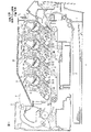
図1は、本発明の画像形成装置の一例としてのプリンタの一実施形態を示す側断面図である。なお、方向について言及する場合には、水平方向に載置したときの方向を基準とし、具体的には、各図に示した方向矢印を基準とする。また、左右方向と幅方向とは、同一方向である。
1. Printer FIG. 1 is a side sectional view showing an embodiment of a printer as an example of an image forming apparatus of the present invention. In addition, when referring to the direction, the direction when placed in the horizontal direction is used as a reference, and specifically, the direction arrow shown in each drawing is used as a reference. Moreover, the left-right direction and the width direction are the same direction.
プリンタ1は、ダイレクトタンデムタイプのカラーLEDプリンタである。図1に示すように、プリンタ1の、装置本体の一例としての本体ケーシング2内には、感光体の一例としての、4つの感光ドラム3が、前後方向に沿って並列配置されている。
以下では、4つの感光ドラム3を、トナー像(後述)の各色(ブラック、イエロー、マゼンタまたはシアン)に対応して、感光ドラム3K(ブラック)、感光ドラム3Y(イエロー)、感光ドラム3M(マゼンタ)、感光ドラム3C(シアン)として区別する。各感光ドラム3には、スコロトロン型帯電器4、LEDユニット5および現像剤担持体の一例としての現像ローラ6が対向配置されている。
The
In the following description, the four
感光ドラム3は、その表面がスコロトロン型帯電器4によって一様に帯電された後、露光ユニットであるLEDユニット5から照射される光によって露光される。これにより、各感光ドラム3の表面には、画像データに基づく静電潜像が形成される。各静電潜像は、現像ローラ6に担持されるトナーによって可視像化され、感光ドラム3の表面上にトナー像が形成される。
The surface of the
用紙Pは、本体ケーシング2内の給紙カセット7に収容されている。給紙カセット7に収容されている用紙Pは、各種ローラにより、搬送ベルト8に給紙される。
搬送ベルト8は、各感光ドラム3K、3Y、3Mおよび3Cと、それらに対向する転写ローラ9との間に配置されている。各感光ドラム3の表面上のトナー像は、転写ローラ9に印加された転写バイアスによって、搬送ベルト8に搬送された用紙P上に転写され、順次重ね合わされる。
The paper P is accommodated in a
The
4色のトナー像が転写された用紙Pは、定着部10に搬送される。用紙P上に転写されたトナー像は、定着部10で熱定着される。その後、用紙Pは、各種ローラにより、排紙トレイ11に排紙される。
2.プロセスカートリッジ
プリンタ1は、各色に対応して、4つのプロセスカートリッジ12を備えている。なお、以下では、4つのプロセスカートリッジ12を、各色に対応して、プロセスカートリッジ12K(ブラック)、プロセスカートリッジ12Y(イエロー)、プロセスカートリッジ12M(マゼンタ)、プロセスカートリッジ12C(シアン)として区別する。
The sheet P on which the four color toner images are transferred is conveyed to the fixing
2. Process Cartridge The
各プロセスカートリッジ12は、本体ケーシング2内に着脱自在に装着されており、前後方向に沿って一方向に並列配置されている。
すなわち、4つのプロセスカートリッジ12は、本体ケーシング2において、後方から前方に向かって、プロセスカートリッジ12K、プロセスカートリッジ12Y、プロセスカートリッジ12M、プロセスカートリッジ12Cの順番で配置されている。
Each process cartridge 12 is detachably mounted in the
That is, the four process cartridges 12 are arranged in the
プロセスカートリッジ12は、感光体カートリッジの一例としてのドラムカートリッジ13と、ドラムカートリッジ13に着脱自在に装着される現像カートリッジ14とを備えている。
すなわち、本体ケーシング2の上壁には、トップカバー34が開閉自在に設けられており、トップカバー34の開放により、各プロセスカートリッジ12を、本体ケーシング2内に着脱させることができる。
(1)ドラムカートリッジ
ドラムカートリッジ13は、ドラムフレーム15を備えている。ドラムフレーム15は、後側下方に配置されるドラム支持部16と、前側上方に配置される現像カートリッジ収容部17とを備えている。ドラム支持部16には、感光ドラム3と、感光ドラム3の後側上方に間隔を隔てて配置されるスコロトロン型帯電器4とが支持されている。
The process cartridge 12 includes a
That is, a
(1) Drum Cartridge The
また、ドラム支持部16には、感光ドラム3に入力される駆動力を受けるドラム側入力カップリング18が設けられている(図2参照)。ドラム側入力カップリング18は、ドラム支持部16から左側へ突出するように設けられている。
プロセスカートリッジ12が本体ケーシング2に装着されると、本体ケーシング2に設けられるドラム側出力カップリング(図示せず)が、トップカバー34の閉鎖に連動して、ドラム側入力カップリング18に向けて進出され、それに嵌合される。ドラム側出力カップリング(図示せず)から出力される駆動力は、ドラム側入力カップリング18を経て、感光ドラム3へ伝達され、それによって、感光ドラム3が回転される。
The
When the process cartridge 12 is mounted on the
なお、ドラム側出力カップリング(図示せず)は、トップカバー34の開放に連動して、ドラム側入力カップリング18から退避される。
また、ドラム支持部16には、ドラム側入力カップリング18の前側上方に、ローラ軸27(後述)を案内するための軸案内溝19(図2参照)が形成されている。
軸案内溝19は、ドラム支持部16の後端縁から、後側下方へ向かって側面視略U字形状に切り欠かれることにより、ドラム支持部16の両側壁に形成されている。
The drum side output coupling (not shown) is retracted from the drum
Further, a shaft guide groove 19 (see FIG. 2) for guiding a roller shaft 27 (described later) is formed in the
The
現像カートリッジ収容部17には、現像カートリッジ14が着脱自在に収容される。
(2)現像カートリッジ
現像カートリッジ14は、筐体21を備えている。筐体21は、後側下方が開放されるボックス形状に形成されている。筐体21では、その前側上方空間が、トナーを収容するトナー収容室22として区画され、その後側下方空間が、現像ローラ6が設けられる現像室23として区画されている。
The
(2) Developer Cartridge The
トナー収容室22には、トナーが充填されており、アジテータ24が回転自在に設けられている。
現像室23には、現像ローラ6とともに、供給ローラ25および層厚規制ブレード26が設けられている。
現像ローラ6は、筐体21の後側下方から露出するように、筐体21の後側下端部に回転自在に支持されている。現像ローラ6は、突起の一例としてのローラ軸27と、そのローラ軸27の周りに設けられるゴムローラ28とを備えている。ローラ軸27の両端部は、筐体21から幅方向両外側へ突出している(図2参照)。
The
In the developing
The developing roller 6 is rotatably supported by the rear lower end portion of the
供給ローラ25は、現像ローラ6の前側上方に対向配置されている。層厚規制ブレード26は、現像ローラ6に上側から圧接されている。
現像カートリッジ14では、画像形成時において、トナー収容室22に充填されているトナーがアジテータ24の回転により、現像室23へ放出され、供給ローラ25へ供給される。その後、トナーは、供給ローラ25の回転により現像ローラ6へ供給される。そして、トナーは、現像ローラ6の回転に伴って、層厚規制ブレード26と現像ローラ6との間に進入し、所定厚さの薄層に形成される。それによって、トナーは、現像ローラ6の表面に薄層として担持される。
The supply roller 25 is disposed to face the upper front side of the developing roller 6. The layer thickness regulating blade 26 is pressed against the developing roller 6 from above.
In the developing
また、筐体21の左側面には、現像側入力カップリング29が設けられている(図2参照)。プロセスカートリッジ12が本体ケーシング2に装着されると、本体ケーシング2に設けられる現像側出力カップリング(図示せず)が、トップカバー34の閉鎖に連動して、現像側入力カップリング29に向けて進出され、それに嵌合される。現像側出力カップリング(図示せず)から出力される駆動力は、現像側入力カップリング29を経て、アジテータ24、供給ローラ25および現像ローラ6へ伝達され、それによって、それらが回転される。
Further, a development-
なお、現像側出力カップリング(図示せず)は、トップカバー34の開放に連動して、現像側入力カップリング29から退避される。
また、筐体21の上端部には、トップカバー34によって押圧される被押圧部30が設けられている(図2参照)。被押圧部30は、幅方向に間隔を隔てて2つ配置されており、筐体21の上端部から上方へ向かって突出するように設けられている。被押圧部30は、バネを内蔵しており、トップカバー34と弾性的に接触される。
The development side output coupling (not shown) is retracted from the development
Further, a pressed
現像カートリッジ14は、ローラ軸27の両端部が、ドラムカートリッジ13の軸案内溝19に、前側上方から挿入され、軸案内溝19に沿って案内されることにより、現像カートリッジ収容部17に装着される(図2参照)。
現像カートリッジ14がドラムカートリッジ13の現像カートリッジ収容部17に装着されると、現像ローラ6と感光ドラム3とが対向配置される。
3.本体ケーシング
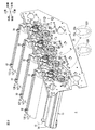
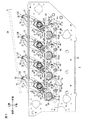
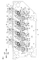
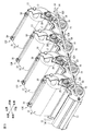
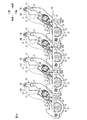
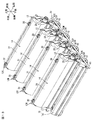
図2は、本体ケーシングの後左方向からの要部斜視図である。図3は、本体ケーシングの要部左側面図(トップカバー開放状態)である。図4は、本体ケーシングの要部左側面図(トップカバー閉鎖状態:フルカラーモード)である。図5は、本体ケーシングの後左方向からの要部斜視図(モノクロモード)である。図6は、本体ケーシングの要部左側面図(モノクロモード)である。図7は、本体ケーシングの後左方向からの要部斜視図(待機モード)である。図8は、本体ケーシングの要部左側面図(待機モード)である。
The developing
When the developing
3. Main Body Casing FIG. 2 is a perspective view of the main part from the rear left direction of the main body casing. FIG. 3 is a left side view of the main part of the main casing (top cover open state). FIG. 4 is a left side view of the main part of the main casing (top cover closed state: full color mode). FIG. 5 is a main part perspective view (monochrome mode) from the rear left direction of the main body casing. FIG. 6 is a left side view of the main part of the main casing (monochrome mode). FIG. 7 is a perspective view of main parts from the rear left direction of the main casing (standby mode). FIG. 8 is a left side view of the main part of the main casing (standby mode).
本体ケーシング2の上面には、図1に示すように、上下方向に開閉されるトップカバー34が設けられている。
また、本体ケーシング2は、図2に示すように、幅方向に間隔を隔てて配置される2つの側板35を備えている。なお、図2では、右側の側板35は省略されている。
(1)側板
側板35には、ドラム側入力カップリング18を案内するためのガイド溝36が、各プロセスカートリッジ12に対応して、4箇所に形成されている。ガイド溝36は、前後方向に間隔を隔ててそれぞれ形成されている。各ガイド溝36は、側板35がその上端縁から後側下方へ向かって斜めに切り欠かれることにより、形成されている。
As shown in FIG. 1, a
Further, as shown in FIG. 2, the
(1) Side
各プロセスカートリッジ12は、図3に示すように、まず、トップカバー34を開放し、本体ケーシング2の上方から、ドラム側入力カップリング18をガイド溝36に挿入し、次いで、ドラム側入力カップリング18をガイド溝36に沿って後側下方へ移動させることにより、本体ケーシング2に装着される。それによって、プロセスカートリッジ12は、上端部が前側上方に向き、下端部が後側下方に向くように、本体ケーシング2に対して傾斜して配置される。
As shown in FIG. 3, each process cartridge 12 first opens the
そして、図4に示すように、トップカバー34を閉鎖すると、トップカバー34の下面が被押圧部30を下方へ向けて押圧し、それによって、現像カートリッジ14は、被押圧部30の反力により下方へ押圧され、常には、現像ローラ6と感光ドラム3とが圧接される。
また、本体ケーシング2には、プロセスカートリッジ12を位置決めするための位置決め機構37と、感光ドラム3から現像ローラ6を離間させるために、現像カートリッジ14のローラ軸27を押圧する、離間部材の一例としての離間機構38とを備えている。
(2)位置決め機構
位置決め機構37は、プロセスカートリッジ12を位置決めするための位置決め部39と、プロセスカートリッジ12を、第1方向の一例としての位置決め方向(前側上方から後側下方へ向かう方向)へ押圧する、第1押圧部材の一例としてのドラム側押圧レバー40と、ドラム側押圧レバー40を揺動させるドラム側リンク機構41とを備えている。
Then, as shown in FIG. 4, when the
In addition, the
(2) Positioning mechanism The
位置決め部39は、ガイド溝36の下端部に2箇所設けられている。一方の位置決め部39は、ガイド溝36の下端部において、下端縁から上方に突出する側面視略矩形状の突部として形成されている。他方の位置決め部39は、ガイド溝36の下端部において、後端縁から前方に突出する側面視略矩形状の突部として形成されている。
ドラム側押圧レバー40は、各ガイド溝36の前側下方にそれぞれ設けられている。ドラム側押圧レバー40の上端部には、後側上方に突出する突起部42が設けられている。ドラム側押圧レバー40の下端部は、側板35に固定されている引張バネ43によって、前側下方へ引っ張られている。ドラム側押圧レバー40の上下方向中間部は、揺動軸44によって揺動自在に支持されている。
Two positioning
The drum
ドラム側リンク機構41は、直動カム45およびリンク板46を備えている。直動カム45は、4つのドラム側押圧レバー40の間にわたって前後方向に延びる細長平板形状に形成されており、ドラム側押圧レバー40の左側側方において対向配置されている。
直動カム45は、本体ケーシング2において、前後方向に直線移動できるように支持されており、図示しないリンク機構により、トップカバー34と連動されている。すなわち、トップカバー34が閉鎖されると、図4に示すように、後方へ直線移動し、トップカバー34が開放されると、図3に示すように、前方へ直線移動する。
The drum
The linear cam 45 is supported in the
リンク板46は、細長い略矩形の板形状に形成されており、各ドラム側押圧レバー40に対応して4つ設けられている。リンク板46の一端部は、ドラム側押圧レバー40の上端部と中間部との間において、揺動自在に固定されている。リンク板46の他端部は、その一端部より前方において、直動カム45に、揺動自在に固定されている。
位置決め機構37では、図3に示すように、トップカバー34が開放されると、直動カム45が前方へ移動され、それによって、リンク板46がドラム側押圧レバー40を前方へ引っ張り、ドラム側押圧レバー40は、引張バネ43の引張力に抗して、揺動軸44を支点として、ガイド溝36から退避するように時計方向へ揺動される。すると、突起部42がドラム側入力カップリング18から離間するように、前方へ移動する。
The
In the
そして、図4に示すように、トップカバー34を閉鎖すると、直動カム45が後方へ移動され、それによって、リンク板46が後方へ移動するので、ドラム側押圧レバー40は、引張バネ43の引張力によって、揺動軸44を支点として、ガイド溝36へ進出するように反時計方向へ揺動される。すると、突起部42がドラム側入力カップリング18を後側下方へ押圧するように、後方へ移動する。
Then, as shown in FIG. 4, when the
そして、突起部42は、ドラム側入力カップリング18を、後側下方に向けて押圧するので、ドラム側入力カップリング18は、2つの位置決め部39と、下側および後側において当接し、それによって、プロセスカートリッジ12が、本体ケーシング2において位置決めされる。
(3)離間機構
離間機構38は、図2および図6に示すように、第2押圧部材の一例としての回転軸51および現像側押圧レバー52(現像側押圧レバー52は、押圧レバーの一例である。)と、支持軸53と、揺動レバー54とを備えている。
And since the
(3) Separation mechanism As shown in FIGS. 2 and 6, the
回転軸51は、4つのガイド溝36の間にわたって前後方向に沿って延びるように、1本設けられている。回転軸51は、4つのガイド溝36の左側側方において、それらと対向配置されるように、本体ケーシング2に回転自在に支持されている。
回転軸51には、本体ケーシング2に設けられるステッピングモータ(図示せず)が接続されており、そのステッピングモータの駆動力により、正面視(前面視)において時計方向に回転される。
One
A stepping motor (not shown) provided in the
現像側押圧レバー52は、4つのプロセスカートリッジ12に対して、4つ設けられている。各現像側押圧レバー52は、側面視において、各ガイド溝36の前側に配置され、回転軸51に支持されている。
現像側押圧レバー52は、回転軸51から、径方向に沿って次第に幅広となるように延びる略台形の平板形状に形成されている。現像側押圧レバー52の自由端部(現像側押圧レバー52における回転軸51に支持されている基端部と反対側の自由端部)には、当接部55が設けられている。当接部55は、現像側押圧レバー52から、さらに径方向に沿って突出するように設けられている。
Four development-side pressing levers 52 are provided for the four process cartridges 12. Each development-side pressing lever 52 is disposed on the front side of each
The development-side pressing lever 52 is formed in a substantially trapezoidal flat plate shape extending from the rotating
当接部55は、ブラックのプロセスカートリッジ12Kに対応する現像側押圧レバー52(以下、ブラック側押圧レバー52Kとする。)には、1つ設けられている(図2の拡大図参照。)。
また、当接部55は、ブラック以外の3色のプロセスカートリッジ12Y、12Mおよび12Cに対応する現像側押圧レバー52(具体的には、プロセスカートリッジ12Yに対応する現像側押圧レバー52Y(イエロー)、プロセスカートリッジ12M(マゼンタ)に対応する現像側押圧レバー52Mおよびプロセスカートリッジ12C(シアン)に対応する現像側押圧レバー52Cであるが、以下、それらを総称して、3色側押圧レバー52YMCとする。)には、回転軸51の周方向において、互いに隣接するように、2つ設けられている(以下、3色側押圧レバー52YMCに設けられる2つの当接部55のうち、回転軸51の回転方向上流側の当接部55を、上流側当接部55aとし、回転軸51の回転方向下流側の当接部55を、下流側当接部55bとする。)(図2の拡大図参照。)。
One
Further, the abutting
そして、3色側押圧レバー52YMCは、前後方向(回転軸51の軸線方向)に投影したときに、すべての上流側当接部55aが重なり、すべての下流側当接部55bが重なるような回転角度で、回転軸51に支持されている。
また、ブラック側押圧レバー52Kは、3色側押圧レバー52YMCに対して、前後方向(回転軸51の軸線方向)に投影したときに、ブラック側押圧レバー52Kの当接部55が、3色側押圧レバー52YMCの下流側当接部55bと重なるような回転角度で、回転軸51に支持されている。
The three-color-side pressing lever 52YMC rotates so that all the
Further, when the black-side
支持軸53は、4つのプロセスカートリッジ12に対して、4つ設けられている。各支持軸53は、プロセスカートリッジ12が本体ケーシング2に装着されているときに、ローラ軸27の下方に配置されるように、側板35に設けられている。支持軸53は、側板35から左側へ突出するように、設けられている。
揺動レバー54は、4つのプロセスカートリッジ12に対して、4つ設けられている。各揺動レバー54は、側面視において略V字形状の平板形状に形成されている。揺動レバー54は、長手方向途中において、支持軸53に揺動自在に支持されている。揺動レバー54の後端部(長手方向一方側端部)は、ローラ軸27と当接できるように、ローラ軸27の下方において、ローラ軸27と対向配置されている。また、揺動レバー54の前端部(長手方向他方側端部)は、現像側押圧レバー52の当接部55によって押圧されるように、左側に膨出しており、当接部55の周方向移動軌跡内に臨み、当接部55が上方から当接されるように、配置されている。
Four
Four swing levers 54 are provided for the four process cartridges 12. Each
そして、離間機構38では、ステッピングモータ(図示せず)の駆動力により、回転軸51が回転すると、現像側押圧レバー52が、自由端部が周方向移動するように、回転される。そして、現像側押圧レバー52に設けられる当接部55が、揺動レバー54の前端部に対して、上方から下方へ向かう第2方向の一例としての作用方向において、当接して押圧する。すると、揺動レバー54が、支持軸53を支点として、左側面視において時計回りに揺動して、揺動レバー54の後端部が、下方からローラ軸27に当接して前側上方へ押圧する。つまり、揺動レバー54の後端部が、ローラ軸27を、軸案内溝19に沿って前側上方へ持ち上げる。すると、現像カートリッジ14は、被押圧部30の押圧力に抗して、前側上方へ持ち上げられて、現像ローラ6と感光ドラム3とが離間する。
In the
その後、回転軸51がさらに回転して、現像側押圧レバー52に設けられる当接部55の揺動レバー54の前端部に対する当接が解除されると、ローラ軸27に対する揺動レバー54の後端部の押圧力が解除されるので、現像カートリッジ14は、被押圧部30の押圧力によって、後側下方へ押圧される。すると、ローラ軸27が、軸案内溝19に沿って後側下方へ移動するとともに、揺動レバー54は、ローラ軸27に後側下方へ押圧されて、支持軸53を支点として、左側面視において反時計回りに揺動される。そして、現像ローラ6と感光ドラム3とが接触する。現像カートリッジ14は、被押圧部30から押圧されるので、現像ローラ6は、感光ドラム3に対して圧接される。
4.プリンタの動作
(1)プロセスユニットの装着
上記したように、図3に示すように、トップカバー34を開放して、本体ケーシング2の上方から、ドラム側入力カップリング18を、ガイド溝36に挿入して、ガイド溝36に沿って後側下方へ移動させれば、プロセスカートリッジ12は、本体ケーシング2に装着される。
Thereafter, when the
4). Operation of Printer (1) Installation of Process Unit As described above, as shown in FIG. 3, the
その後、図4に示すように、トップカバー34を閉鎖すると、現像カートリッジ14は、被押圧部30の反力により下方へ押圧され、常には、現像ローラ6と感光ドラム3とが圧接される。
また、トップカバー34の閉鎖に連動して、直動カム45が後方へ移動されるので、ドラム側押圧レバー40は、引張バネ43の引張力によって、揺動軸44を支点として揺動され、突起部42がドラム側入力カップリング18を後側下方へ押圧する。これによって、ドラム側入力カップリング18が、2つの位置決め部39と、下側および後側において当接して、プロセスカートリッジ12が、本体ケーシング2に対して位置決めされる。
(2)画像形成動作
そして、このプリンタ1では、画像形成時において、すべての感光ドラム3K、3Y、3Mおよび3Cに現像ローラ6を圧接させるフルカラーモードと、画像形成時において、ブラックの感光ドラム3Kのみに現像ローラ6を圧接させるモノクロモードと、非画像形成時において、すべての感光ドラム3から現像ローラ6を離間させる待機モードとに、適宜切り替えられる。
Thereafter, as shown in FIG. 4, when the
Further, since the linear cam 45 is moved rearward in conjunction with the closing of the
(2) Image Forming Operation In the
具体的には、このプリンタ1では、フルカラーモードおよびモノクロモードと、待機モードとは、本体ケーシング2に設けられるCPU(図示せず)により、ステッピングモータ(図示せず)が制御されて、画像形成時および非画像形成時に対応して、自動的に切り替えられる。
一方、フルカラーモードとモノクロモードとは、画像データに含まれる指令、または、操作パネル(図示せず)からの入力により、CPU(図示せず)によって、選択的に切り替えられる。
Specifically, in the
On the other hand, the full color mode and the monochrome mode are selectively switched by a CPU (not shown) in response to a command included in the image data or an input from an operation panel (not shown).
フルカラーモードでは、図2および図4に示すように、ステッピングモータにより、回転軸51を回転させて、すべての現像側押圧レバー52の当接部55が、それに対応する揺動レバー54から離間する全離間位置を取る回転角度に、回転軸51を位置させる。
すると、すべての現像側押圧レバー52の当接部55の、揺動レバー54に対する当接が解除されるので、上記したように、現像カートリッジ14は、被押圧部30の押圧力によって後側下方へ押圧され、すべての感光ドラム3に対して、対応する現像ローラ6が圧接される。
In the full color mode, as shown in FIGS. 2 and 4, the rotating
Then, the
これによって、フルカラーモードの画像形成時には、すべての感光ドラム3K、3Y、3Mおよび3Cにトナー像が形成されて、用紙Pには、4色の重ね合わせにより、フルカラー画像が形成される。
モノクロモードでは、図5および図6に示すように、ステッピングモータにより、回転軸51を回転させて、3色側押圧レバー52YMCの上流側当接部55aが、それに対応する揺動レバー54を下方へ押圧し、ブラック側押圧レバー52Kの当接部55が、それに対応する揺動レバー54から離間する、部分当接位置の一例としてのブラック離間位置を取る回転角度に、回転軸51を位置させる。
Thus, at the time of image formation in the full color mode, toner images are formed on all the
In the monochrome mode, as shown in FIGS. 5 and 6, the
すると、3色側押圧レバー52YMCの上流側当接部55aが、それに対応する揺動レバー54を下方へ押圧するので、上記したように、その揺動レバー54がローラ軸27を前側上方へ持ち上げる。すると、ブラック以外の現像カートリッジ14は、被押圧部30の押圧力に抗して、前側上方へ持ち上げられて、現像ローラ6と、ブラック以外の3色の感光ドラム3Y、3Mおよび3Cとが離間する。
Then, the
一方、ブラック側押圧レバー52Kの当接部55の、揺動レバー54に対する当接は、解除されるので、上記したように、ブラックの現像カートリッジ14は、被押圧部30の押圧力によって後側下方へ押圧され、ブラックの感光ドラム3Kに対して、対応する現像ローラ6が圧接される。
これによって、モノクロモードの画像形成時には、ブラックの感光ドラム3Kのみにトナー像が形成されるので、用紙Pには、白黒のモノクロ画像が形成される。
On the other hand, since the contact of the
Thus, when a monochrome mode image is formed, a toner image is formed only on the black
待機モードでは、図7および図8に示すように、ステッピングモータにより、回転軸51を回転させて、3色側押圧レバー52YMCの下流側当接部55bが、それに対応する揺動レバー54を下方へ押圧し、ブラック側押圧レバー52Kの当接部55が、それに対応する揺動レバー54を下方へ押圧する全当接位置を取る回転角度に、回転軸51を位置させる。
In the standby mode, as shown in FIGS. 7 and 8, the rotating
すると、3色側押圧レバー52YMCの下流側当接部55b、および、ブラック側押圧レバー52Kの当接部55が、それに対応するすべての揺動レバー54を下方へ押圧するので、上記したように、その揺動レバー54がすべてのローラ軸27を前側上方へ持ち上げる。すると、すべての現像カートリッジ14は、被押圧部30の押圧力に抗して、前側上方へ持ち上げられて、現像ローラ6と、すべての感光ドラム3K、3Y、3Mおよび3Cとが離間する。
Then, the
これによって、非画像形成時には、すべての感光ドラム3K、3Y、3Mおよび3Cから現像ローラ6が離間される。
そして、回転軸51は、上記したように、ステッピングモータにより回転角度が制御されて、全離間位置、ブラック離間位置および全当接位置を順次取るように、正面視(前面視)において時計方向に1回転される。
As a result, the developing roller 6 is separated from all the
Then, as described above, the rotation angle of the
回転軸51が1回転する間に、3色側押圧レバー52YMCは、揺動レバー54と2回当接する。すなわち、上流側当接部55aが、ブラック離間位置において揺動レバー54と当接し、下流側当接部55bが、全当接位置において揺動レバー54と当接する。
一方、回転軸51が1回転する間に、ブラック側押圧レバー52Kは、揺動レバー54と1回当接する。すなわち、ブラック側押圧レバー52Kの当接部55は、全当接位置において揺動レバー54と当接する。
(3)プロセスユニットの離脱
そして、非画像形成時には、上記したように、回転軸51が全当接位置に位置され、現像ローラ6と、すべての感光ドラム3K、3Y、3Mおよび3Cとが離間しているので、図3に示すように、トップカバー34を開放すれば、そのトップカバー34の開放に連動して、直動カム45が前方へ移動される。すると、リンク板46がドラム側押圧レバー40を前方へ引っ張り、ドラム側押圧レバー40が、引張バネ43の引張力に抗して、揺動軸44を支点として揺動され、突起部42がドラム側入力カップリング18から離間する。
While the
On the other hand, while the rotating
(3) Separation of process unit At the time of non-image formation, as described above, the rotating
その後、プロセスカートリッジ12を、ガイド溝36に沿って前側上方へ引き抜けば、プロセスカートリッジ12が、本体ケーシング2から離脱される。
5.実施形態の作用効果
(1)プリンタ1において、プロセスカートリッジ12の本体ケーシング2に対する位置決めでは、ドラム側押圧レバー40の突起部42が、ドラム側入力カップリング18を後側下方へ押圧して、ドラム側入力カップリング18を、2つの位置決め部39と、下側および後側において当接させる。
Thereafter, the process cartridge 12 is detached from the
5. Effects of Embodiment (1) In the
一方、感光ドラム3から現像ローラ6を離間させるには、ステッピングモータにより回転軸51を回転させて、現像側押圧レバー52の当接部55により、揺動レバー54を下方へ押圧する。すると、揺動レバー54がローラ軸27を前側上方へ持ち上げて、感光ドラム3から現像ローラ6が離間される。
そして、プリンタ1では、位置決め部39に対して、ドラム側押圧レバー40がドラム側入力カップリング18を後側下方へ押圧する位置決め方向と、現像側押圧レバー52の当接部55が、揺動レバー54を下方へ押圧する作用方向とが、ともに略同一方向の下方である。
On the other hand, in order to separate the developing roller 6 from the
In the
そのため、プロセスカートリッジ12を本体ケーシング2に位置決めした後に、現像ローラ6を感光ドラム3に対して離間させても、位置決め方向と作用方向とが略同一方向であるため、本体ケーシング2に対してプロセスカートリッジ12が位置ずれすることや、振動が生じることを抑制することができる。その結果、画像形成精度の低下を防止し、画像形成時の補正時間の短縮を図ることができる。
(2)離間機構38では、現像側押圧レバー52の当接部55の押圧により、揺動レバー54が揺動し、その揺動レバー54の後端部が、ローラ軸27を押圧することにより、現像ローラ6が感光ドラム3から離間する方向へ、現像カートリッジ14が移動される。そのため、揺動レバー54の揺動により、簡易かつ確実に、現像ローラ6を感光ドラム3から離間させることができる。
(3)また、離間機構38では、現像側押圧レバー52が回転軸51を支点として回動されることにより、当接部55が揺動レバー54を押圧する。そのため、揺動レバー54の揺動により、簡易かつ確実に、現像ローラ6を感光ドラム3から離間させることができる。また、回転軸51が、支持軸53の軸方向と直交する前後方向に沿って延びているので、支持軸53の軸方向(つまり、幅方向)における小型化を図ることができる。
(4)また、離間機構38では、1本の回転軸51を回転させることにより、4つの現像カートリッジ14に対応する現像側押圧レバー52が回動して、それに対応する揺動レバー54が押圧される。すると、各揺動レバー54の揺動により、それに対応するローラ軸27が押圧されて、現像ローラ6が感光ドラム3から離間する方向へ、現像カートリッジ14が移動される。そのため、1本の回転軸51を回転させれば、すべての現像カートリッジ14を、現像ローラ6が感光ドラム3から離間する方向へ移動させることができる。
(5)さらに、離間機構38では、回転軸51の回転角度をステッピングモータにより順次変化させれば、全当接位置では、3色側押圧レバー52YMCの下流側当接部55b、および、ブラック側押圧レバー52Kの当接部55が、それに対応するすべての揺動レバー54を下方へ押圧する。そのため、現像ローラ6を、すべての感光ドラム3K、3Y、3Mおよび3Cから離間させることができる。
Therefore, even if the developing roller 6 is separated from the
(2) In the
(3) In the
(4) Further, in the
(5) Further, in the
また、ブラック離間位置では、3色側押圧レバー52YMCの上流側当接部55aが、それに対応する揺動レバー54を下方へ押圧する一方、ブラック側押圧レバー52Kの当接部55の、揺動レバー54に対する当接が解除される。そのため、ブラックの感光ドラム3Kのみに対して、対応する現像ローラ6を圧接させることができる。
また、全離間位置では、すべての現像側押圧レバー52の当接部55が、それに対応する揺動レバー54から離間する。そのため、すべての感光ドラム3に対して、対応する現像ローラ6を圧接させることができる。
In the black separation position, the
Further, in the fully separated position, the
その結果、回転軸51を回転させる簡易な構成により、現像ローラ6の感光ドラム3に対する離間モード、すなわち、待機モード、モノクロモードおよびフルカラーモードを切り替えることができる。
(6)そして、ブラック側押圧レバー52Kでは、回転軸51が1回転する間に、当接部55を揺動レバー54に対して1回当接させ、また、3色側押圧レバー52YMCでは、回転軸51が1回転する間に、上流側当接部55aおよび下流側当接部55bを揺動レバー54に対してそれぞれ1回、つまり、2回当接させている。そのため、上記離間モードの切り替えを、簡易な構成により達成することができる。
(7)換言すると、ブラック側押圧レバー52Kには、1つの当接部55を設け、3色側押圧レバー52YMCには、上流側当接部55aおよび下流側当接部55bの2つの当接部55を設けているので、当接回数に対応して、当接部55の数を変更する簡易な構成により、上記離間モードの切り替えを、簡易な構成により達成することができる。
6.他の実施形態
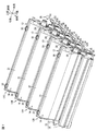
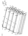
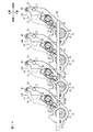
図9は、他の実施形態の本体ケーシングの後左方向からの要部斜視図(フルカラーモード)である。図10は、図9に示す本体ケーシングの要部左側面図(フルカラーモード)である。図11は、図9に示す本体ケーシングの後左方向からの要部斜視図(モノクロモード)である。図12は、図9に示す本体ケーシングの要部左側面図(モノクロモード)である。図13は、図9に示す本体ケーシングの後左方向からの要部斜視図(待機モード)である。図14は、図9に示す本体ケーシングの要部左側面図(待機モード)である。
As a result, the separation mode of the developing roller 6 with respect to the
(6) Then, in the black side
(7) In other words, the black-side
6). Other Embodiments FIG. 9 is a perspective view (full color mode) of a main part from the rear left direction of the main body casing according to another embodiment. FIG. 10 is a left side view of the main part of the main casing shown in FIG. 9 (full color mode). 11 is a perspective view (monochrome mode) of the main part from the rear left direction of the main casing shown in FIG. 12 is a left side view (monochrome mode) of the main part of the main casing shown in FIG. 13 is a perspective view (standby mode) of the main part from the rear left direction of the main casing shown in FIG. FIG. 14 is a left side view (standby mode) of the main part of the main casing shown in FIG.
上記の説明では、離間機構38において、回転軸51および現像側押圧レバー52を設けたが、それらに代替して、図9に示すように、第2押圧部材の一例として、スライド板61を設けることもできる。
なお、以下に説明する他の実施形態は、回転軸51および現像側押圧レバー52に代替して、スライド板61を設けている以外は、上記した実施形態と同一構成であり、上記した位置決め機構37などを備えている。また、以下の説明および図9ないし図14において、上記した部材と同様の部材には、同一の参照符号を付し、その説明を省略する。
(1)離間機構
離間機構38は、図9に示すように、スライド板61と、上記した支持軸53および揺動レバー54とを備えている。
In the above description, in the
The other embodiment described below has the same configuration as that of the above-described embodiment except that the
(1) Separation Mechanism As shown in FIG. 9, the
スライド板61は、上下方向に平板の細長い矩形状に形成されている。スライド板61は、4つのガイド溝36の間にわたって前後方向に沿って延びるように、1本設けられている。スライド板61は、4つのガイド溝36の左側側方において、それらと対向配置されるように、本体ケーシング2にスライド自在に支持されている。
スライド板61には、本体ケーシング2に設けられるステッピングモータ(図示せず)が接続されており、そのステッピングモータの駆動力により、前後方向にスライドする。
The
A stepping motor (not shown) provided in the
スライド板61には、4つのプロセスカートリッジ12に対応して、押圧部62が設けられている。各押圧部62は、フルカラーモードにおいて、各ガイド溝36の前方に配置される。
押圧部62は、スライド板61から右側へ膨出する略矩形ブロック形状に形成されており、スライド板61と一体的に設けられている。押圧部62の後端面は、図12に示すように、前側下端から後側上端に向かう傾斜面として形成されている。
The
The pressing portion 62 is formed in a substantially rectangular block shape that bulges rightward from the
また、ブラックのプロセスカートリッジ12Kに対応する押圧部62(以下、ブラック側押圧部62Kとする。)の下端面は、ブラック以外の3色のプロセスカートリッジ12Y、12Mおよび12Cに対応する押圧部62(具体的には、プロセスカートリッジ12Y(イエロー)に対応する押圧部62Y、プロセスカートリッジ12M(マゼンタ)に対応する押圧部62Mおよびプロセスカートリッジ12C(シアン)に対応する押圧部62Cであるが、以下、それらを総称して、3色側押圧部62YMCとする。)の下端面よりも、前後方向に短く形成されている。
Further, the lower end surface of the pressing portion 62 corresponding to the
具体的には、ブラック側押圧部62Kの下端面は、待機モードのときのみに、揺動レバー54を押圧する長さで形成されている。また、3色側押圧部62YMCは、モノクロモードおよび待機モードの両方のときに、揺動レバー54を押圧する長さで形成されている。
そして、離間機構38では、ステッピングモータ(図示せず)の駆動力により、スライド板61が後方にスライドすると、押圧部62の後端面が揺動レバー54の前端部に当接し、押圧部62の後端面の傾斜角度に沿って、揺動レバー54の前端部が上方から下方へ向かう第2方向の一例としての作用方向において、押圧部62が揺動レバー54の前端部に乗り上げて、押圧部62の下端面が揺動レバー54の前端部を押圧する。
Specifically, the lower end surface of the black side
In the
すると、揺動レバー54が、支持軸53を支点として、左側面視において時計回りに揺動して、揺動レバー54の後端部が、下方からローラ軸27に当接して前側上方へ押圧する。つまり、揺動レバー54の後端部が、ローラ軸27を、軸案内溝19に沿って前側上方へ持ち上げる。すると、現像カートリッジ14は、被押圧部30の押圧力に抗して、前側上方へ持ち上げられて、現像ローラ6と感光ドラム3とが離間する。
Then, the
その後、ステッピングモータ(図示せず)の駆動力により、スライド板61が前方にスライドすると、図10に示すように、押圧部62が揺動レバー54から離間する。すると、ローラ軸27に対する揺動レバー54の後端部の押圧力が解除されるので、現像カートリッジ14は、被押圧部30の押圧力によって、後側下方へ押圧される。すると、ローラ軸27が、軸案内溝19に沿って後側下方へ移動するとともに、揺動レバー54は、ローラ軸27に後側下方へ押圧されて、支持軸53を支点として、左側面視において反時計回りに揺動される。
Thereafter, when the
そして、現像ローラ6と感光ドラム3とが接触する。現像カートリッジ14は、被押圧部30から押圧されるので、現像ローラ6は、感光ドラム3に対して圧接される。
(2)画像形成動作
そして、他の実施形態では、フルカラーモード、モノクロモードおよび待機モードが、下記のように切り替えられる。
Then, the developing roller 6 and the
(2) Image Forming Operation In another embodiment, the full color mode, the monochrome mode, and the standby mode are switched as follows.
すなわち、フルカラーモードでは、図9および図10に示すように、ステッピングモータにより、スライド板61を前方へスライドさせて、すべての押圧部62がそれに対応する揺動レバー54から離間する全離間位置(最前方位置)に位置させる。
すると、すべての押圧部62の揺動レバー54に対する当接が解除されるので、上記したように、現像カートリッジ14は、被押圧部30の押圧力によって後側下方へ押圧され、すべての感光ドラム3に対して、対応する現像ローラ6が圧接される。
That is, in the full color mode, as shown in FIG. 9 and FIG. 10, the
Then, the contact of all the pressing portions 62 with respect to the
これによって、フルカラーモードの画像形成時には、すべての感光ドラム3K、3Y、3Mおよび3Cにトナー像が形成されて、用紙Pには、4色の重ね合わせにより、フルカラー画像が形成される。
モノクロモードでは、図11および図12に示すように、ステッピングモータにより、スライド板61を後方へスライドさせて、3色側押圧部62YMCが、それに対応する揺動レバー54を下方へ押圧し、ブラック側押圧部62Kが、それに対応する揺動レバー54から離間する、部分当接位置の一例としてのブラック離間位置(中間位置)に位置させる。
Thus, at the time of image formation in the full color mode, toner images are formed on all the
In the monochrome mode, as shown in FIG. 11 and FIG. 12, the
すると、3色側押圧部62YMCが、それに対応する揺動レバー54を下方へ押圧するので、上記したように、その揺動レバー54がローラ軸27を前側上方へ持ち上げる。すると、ブラック以外の現像カートリッジ14は、被押圧部30の押圧力に抗して、前側上方へ持ち上げられて、現像ローラ6と、ブラック以外の3色の感光ドラム3Y、3Mおよび3Cとが離間する。
Then, since the three-color-side pressing portion 62YMC presses the
一方、ブラック側押圧部62Kの揺動レバー54に対する当接は、解除されるので、上記したように、ブラックの現像カートリッジ14は、被押圧部30の押圧力によって後側下方へ押圧され、ブラックの感光ドラム3Kに対して、対応する現像ローラ6が圧接される。
これによって、モノクロモードの画像形成時には、ブラックの感光ドラム3Kのみにトナー像が形成されるので、用紙Pには、白黒のモノクロ画像が形成される。
On the other hand, since the contact of the black-side
Thus, when a monochrome mode image is formed, a toner image is formed only on the black
待機モードでは、図13および図14に示すように、ステッピングモータにより、スライド板61を、さらに後方へスライドさせて、すべての押圧部62がそれに対応する揺動レバー54を下方へ押圧する全当接位置(最後方位置)に位置させる。
すると、すべての押圧部62がそれに対応するすべての揺動レバー54を下方へ押圧するので、上記したように、揺動レバー54がすべてのローラ軸27を前側上方へ持ち上げる。すると、すべての現像カートリッジ14は、被押圧部30の押圧力に抗して、前側上方へ持ち上げられて、現像ローラ6と、すべての感光ドラム3K、3Y、3Mおよび3Cとが離間する。
In the standby mode, as shown in FIGS. 13 and 14, the
Then, since all the pressing parts 62 press all the corresponding rocking levers 54 downward, as described above, the rocking levers 54 lift all the
これによって、非画像形成時には、すべての感光ドラム3K、3Y、3Mおよび3Cから現像ローラ6が離間される。
そして、スライド板61は、上記したように、ステッピングモータにより前後方向にスライドされて、その1往復(1ストローク)の間に、全離間位置(最前方位置)、ブラック離間位置(中間位置)および全当接位置(最後方位置)に位置される。
As a result, the developing roller 6 is separated from all the
Then, as described above, the
スライド板61が1往復する間に、3色側押圧部62YMCは、ブラック離間位置(中間位置)および全当接位置(最後方位置)において、揺動レバー54と連続的に2回(長い時間)当接する。
一方、スライド板61が1往復する間に、ブラック側押圧部62Kは、全当接位置(最後方位置)において、揺動レバー54と1回(短い時間)当接する。
(3)他の実施形態の作用効果
(3−1)そして、他の実施形態のプリンタ1でも、図示しないが、プロセスカートリッジ12の本体ケーシング2に対する位置決めでは、ドラム側押圧レバー40の突起部42が、ドラム側入力カップリング18を後側下方へ押圧して、ドラム側入力カップリング18を、2つの位置決め部39と、下側および後側において当接させる。
While the
On the other hand, while the
(3) Operational Effects of Other Embodiments (3-1) Also in the
一方、感光ドラム3から現像ローラ6を離間させるには、ステッピングモータによりスライド板61をスライドさせて、押圧部62により、揺動レバー54を下方へ押圧する。すると、揺動レバー54がローラ軸27を前側上方へ持ち上げて、感光ドラム3から現像ローラ6が離間される。
そして、プリンタ1では、位置決め部39に対して、ドラム側押圧レバー40がドラム側入力カップリング18を後側下方へ押圧する位置決め方向と、押圧部62が、揺動レバー54を下方へ押圧する作用方向とが、ともに略同一方向の下方である。
On the other hand, in order to separate the developing roller 6 from the
In the
そのため、プロセスカートリッジ12を本体ケーシング2に位置決めした後に、現像ローラ6を感光ドラム3に対して離間させても、位置決め方向と作用方向とが略同一方向であるため、本体ケーシング2に対してプロセスカートリッジ12が位置ずれすることや、振動が生じることを抑制することができる。その結果、画像形成精度の低下を防止し、画像形成時の補正時間の短縮を図ることができる。
(3−2)離間機構38では、押圧部62の押圧により、揺動レバー54が揺動し、その揺動レバー54の後端部が、ローラ軸27を押圧することにより、現像ローラ6が感光ドラム3から離間する方向へ、現像カートリッジ14が移動される。そのため、揺動レバー54の揺動により、簡易かつ確実に、現像ローラ6を感光ドラム3から離間させることができる。
(3−3)また、離間機構38では、押圧部62が揺動レバー54を押圧する。そのため、揺動レバー54の揺動により、簡易かつ確実に、現像ローラ6を感光ドラム3から離間させることができる。また、スライド板61が、支持軸53の軸方向と直交する前後方向に沿って延びているので、支持軸53の軸方向(つまり、幅方向)における小型化を図ることができる。
(3−4)また、離間機構38では、1本のスライド板61をスライドさせることにより、4つの現像カートリッジ14に対応する押圧部62が前後方向に移動して、それに対応する揺動レバー54が押圧される。すると、各揺動レバー54の揺動により、それに対応するローラ軸27が押圧されて、現像ローラ6が感光ドラム3から離間する方向へ、現像カートリッジ14が移動される。そのため、1本のスライド板61をスライドさせれば、すべての現像カートリッジ14を、現像ローラ6が感光ドラム3から離間する方向へ移動させることができる。
(3−5)さらに、離間機構38では、スライド板61の前後方向位置をステッピングモータにより順次変化させれば、全当接位置(最後方位置)では、すべての押圧部62がそれに対応する揺動レバー54を下方へ押圧する。そのため、現像ローラ6を、すべての感光ドラム3K、3Y、3Mおよび3Cから離間させることができる。
Therefore, even if the developing roller 6 is separated from the
(3-2) In the
(3-3) In the
(3-4) Further, in the
(3-5) Further, in the
また、ブラック離間位置(中間位置)では、3色側押圧部62YMCが、それに対応する揺動レバー54を下方へ押圧する一方、ブラック側押圧部62Kの揺動レバー54に対する当接が解除される。そのため、ブラックの感光ドラム3Kのみに対して、対応する現像ローラ6を圧接させることができる。
また、全離間位置(最前方位置)では、すべての押圧部62が、それに対応する揺動レバー54から離間する。そのため、すべての感光ドラム3に対して、対応する現像ローラ6を圧接させることができる。
At the black separation position (intermediate position), the three-color-side pressing portion 62YMC presses the
Further, at the fully separated position (frontmost position), all the pressing portions 62 are separated from the corresponding swing levers 54. Therefore, the corresponding developing roller 6 can be pressed against all the
その結果、スライド板61をスライドさせる簡易な構成により、現像ローラ6の感光ドラム3に対する離間モード、すなわち、待機モード、モノクロモードおよびフルカラーモードを切り替えることができる。
(3−6)そして、ブラック側押圧部62Kは、スライド板61が1往復する間に、揺動レバー54に対して1回(短い時間)当接し、また、3色側押圧部62YMCは、スライド板61が1往復する間に、揺動レバー54に対して、連続的に2回(長い時間)当接しており、それにより、上記離間モードの切り替えを、簡易な構成により達成することができる。
(3−7)換言すると、ブラック側押圧部62Kの下端面は、3色側押圧部62YMCの下端面よりも、前後方向に短く形成されており、下端面の長さを変更する簡易な構成により、上記離間モードの切り替えを、簡易な構成により達成することができる。
7.その他変形例
なお、上記した2つの実施形態では、4つの感光ドラムを備えるダイレクトタンデムタイプのカラープリンタを例示したが、本発明の画像形成装置には、たとえば、中間転写タンデムタイプのカラープリンタや、モノクロプリンタなど、電子写真方式のすべてのプリンタが含まれる。
As a result, the separation mode of the developing roller 6 with respect to the
(3-6) Then, the black-side
(3-7) In other words, the lower end surface of the black-side
7). Other Modifications In the above-described two embodiments, a direct tandem type color printer including four photosensitive drums is illustrated. However, the image forming apparatus of the present invention includes, for example, an intermediate transfer tandem type color printer, This includes all electrophotographic printers such as monochrome printers.
1 プリンタ
2 本体ケーシング
3 感光ドラム
6 現像ローラ
12 プロセスカートリッジ
13 ドラムカートリッジ
14 現像カートリッジ
27 ローラ軸
38 離間機構
39 位置決め部
40 ドラム側押圧レバー
51 回転軸
52 現像側押圧レバー
53 支持軸
54 揺動レバー
55 当接部
61 スライド板
62 押圧部
DESCRIPTION OF
Claims (2)
感光体を有する感光体カートリッジと、前記感光体に接触するように配置されるとともに現像剤を担持する現像剤担持体を有する現像カートリッジとを備え、前記装置本体に着脱自在に装着されるプロセスカートリッジと、
前記プロセスカートリッジを位置決めするために、前記装置本体に設けられる位置決め部に対し、前記感光体カートリッジを第1方向へ押圧する第1押圧部材と、
前記現像剤担持体を前記感光体に対して前記第1方向と反対方向へ離間するように、前記現像カートリッジに作用する離間部材であって、第2方向へ押圧することにより前記現像剤担持体を前記感光体に対して離間することが可能な第2押圧部材を少なくとも有する離間部材と、を備え、
前記現像カートリッジは、
突起を備え、
前記離間部材は、さらに、
支持軸と、
長手方向途中が前記支持軸に揺動自在に支持され、前記支持軸に対して長手方向一方側が前記突起に当接し、長手方向他方側が前記第2押圧部材により押圧される揺動レバーとを備え、
前記第2押圧部材の押圧により、前記揺動レバーを揺動させて、前記揺動レバーの長手方向一方側で前記突起を押圧することにより、前記現像カートリッジを、前記現像剤担持体が前記感光体から離間する方向へ移動させ、
前記第2押圧部材は、
前記支持軸の軸方向と直交する方向に沿って延び、回転自在に支持される回転軸と、
前記回転軸に設けられ、前記揺動レバーを押圧する押圧レバーと
を備え、
前記プロセスカートリッジは、一方向に並列して複数設けられ、
前記支持軸、前記揺動レバーおよび前記押圧レバーは、複数の前記現像カートリッジの前記突起に対して、複数設けられており、
前記回転軸は、複数の前記押圧レバーを支持し、複数の前記現像カートリッジの並列方向に沿って1本設けられ、
前記回転軸は、回転角度により、すべての前記押圧レバーを前記揺動レバーに当接させる全当接位置と、少なくとも1つの押圧レバーを前記揺動レバーに当接させず、残りの押圧レバーを前記揺動レバーに当接させる部分当接位置と、すべての前記押圧レバーを前記揺動レバーに当接させない全離間位置とを取るように、回転し、
複数の前記押圧レバーのうち、少なくとも1つの押圧レバーは、前記回転軸が1回転する間に、前記揺動レバーに対して1回当接するように、設けられており、
残りの押圧レバーは、前記回転軸が1回転する間に、前記揺動レバーに対して2回当接するように、設けられていることを特徴とする、画像形成装置。 The device body;
A process cartridge that includes a photosensitive cartridge having a photosensitive member and a developing cartridge that is disposed so as to be in contact with the photosensitive member and has a developer carrying member that carries the developer, and is detachably attached to the apparatus main body. When,
A first pressing member that presses the photosensitive cartridge in a first direction against a positioning portion provided in the apparatus main body to position the process cartridge;
A separation member acting on the developing cartridge to separate the developer carrier from the photosensitive member in a direction opposite to the first direction, and pressing the developer carrier in a second direction A separation member having at least a second pressing member that can be separated from the photoconductor ,
The developing cartridge is
With protrusions,
The spacing member further includes
A support shaft;
A swing lever that is supported by the support shaft in a swingable manner in the longitudinal direction, one side in the longitudinal direction of the support shaft abuts on the protrusion, and the other side in the longitudinal direction is pressed by the second pressing member. ,
When the second pressing member is pressed, the swing lever is swung, and the protrusion is pressed on one side in the longitudinal direction of the swing lever. Move it away from the body,
The second pressing member is
A rotating shaft that extends along a direction orthogonal to the axial direction of the support shaft and is rotatably supported;
A pressing lever provided on the rotating shaft and pressing the swing lever;
With
A plurality of the process cartridges are provided in parallel in one direction,
A plurality of the support shaft, the swing lever, and the pressing lever are provided for the protrusions of the plurality of developer cartridges,
The rotating shaft supports a plurality of the pressing levers, and is provided along a parallel direction of the plurality of developing cartridges,
The rotating shaft has a total contact position where all the pressing levers contact the swing lever according to a rotation angle, and at least one press lever does not contact the swing lever, and the remaining press levers Rotate to take a partial contact position to contact the swing lever and a fully spaced position where all the press levers do not contact the swing lever,
Among the plurality of pressing levers, at least one pressing lever is provided so as to come into contact with the swing lever once while the rotating shaft makes one rotation,
The remaining pressing lever is provided so as to come into contact with the swing lever twice during one rotation of the rotating shaft.
前記回転軸が1回転する間に前記揺動レバーに対して2回当接する押圧レバーは、前記揺動レバーに当接する当接部を2つ備えていることを特徴とする、請求項1に記載の画像形成装置。 The pressing lever that contacts the swing lever once while the rotating shaft makes one rotation includes one contact portion that contacts the swing lever,
Said rotary shaft is twice abuts the push lever against the swing lever during one rotation is characterized in that it comprises two abutments abutting on said swinging lever, to claim 1 The image forming apparatus described.
Priority Applications (2)
| Application Number | Priority Date | Filing Date | Title |
|---|---|---|---|
| JP2007340750A JP4919085B2 (en) | 2007-12-28 | 2007-12-28 | Image forming apparatus |
| US12/340,897 US8213830B2 (en) | 2007-12-28 | 2008-12-22 | Image forming apparatus in which developer carrying members can be separated from photosensitive members |
Applications Claiming Priority (1)
| Application Number | Priority Date | Filing Date | Title |
|---|---|---|---|
| JP2007340750A JP4919085B2 (en) | 2007-12-28 | 2007-12-28 | Image forming apparatus |
Publications (2)
| Publication Number | Publication Date |
|---|---|
| JP2009162903A JP2009162903A (en) | 2009-07-23 |
| JP4919085B2 true JP4919085B2 (en) | 2012-04-18 |
Family
ID=40965623
Family Applications (1)
| Application Number | Title | Priority Date | Filing Date |
|---|---|---|---|
| JP2007340750A Expired - Fee Related JP4919085B2 (en) | 2007-12-28 | 2007-12-28 | Image forming apparatus |
Country Status (2)
| Country | Link |
|---|---|
| US (1) | US8213830B2 (en) |
| JP (1) | JP4919085B2 (en) |
Families Citing this family (13)
| Publication number | Priority date | Publication date | Assignee | Title |
|---|---|---|---|---|
| JP4995211B2 (en) | 2008-09-29 | 2012-08-08 | キヤノン株式会社 | Electrophotographic image forming apparatus |
| JP4549426B2 (en) | 2008-09-29 | 2010-09-22 | キヤノン株式会社 | Electrophotographic image forming apparatus |
| JP4689750B2 (en) * | 2008-09-29 | 2011-05-25 | キヤノン株式会社 | Electrophotographic image forming apparatus |
| JP4692626B2 (en) * | 2008-12-26 | 2011-06-01 | ブラザー工業株式会社 | Image forming apparatus and developing cartridge |
| JP5590894B2 (en) * | 2010-01-13 | 2014-09-17 | キヤノン株式会社 | Image forming apparatus |
| JP5062277B2 (en) * | 2010-03-19 | 2012-10-31 | ブラザー工業株式会社 | Image forming apparatus |
| JP5240314B2 (en) | 2011-03-31 | 2013-07-17 | ブラザー工業株式会社 | Image forming apparatus |
| JP5652301B2 (en) | 2011-03-31 | 2015-01-14 | ブラザー工業株式会社 | Image forming apparatus |
| JP5418533B2 (en) | 2011-03-31 | 2014-02-19 | ブラザー工業株式会社 | Image forming apparatus |
| JP5966809B2 (en) * | 2012-09-21 | 2016-08-10 | ブラザー工業株式会社 | Image forming apparatus |
| JP5954086B2 (en) * | 2012-09-28 | 2016-07-20 | ブラザー工業株式会社 | Image forming apparatus |
| CN107111269B (en) * | 2014-11-28 | 2020-12-29 | 佳能株式会社 | Cartridge, member constituting cartridge, and image forming apparatus |
| BR122018074174B1 (en) * | 2014-11-28 | 2023-12-19 | Canon Kabushiki Kaisha | CARTRIDGE MOUNTABLE TO A MAIN APPARATUS ASSEMBLY OF AN IMAGE FORMING APPARATUS |
Family Cites Families (12)
| Publication number | Priority date | Publication date | Assignee | Title |
|---|---|---|---|---|
| JP2988104B2 (en) * | 1992-02-25 | 1999-12-06 | 富士通株式会社 | Lock mechanism for developer support cart |
| JPH08123281A (en) * | 1994-10-20 | 1996-05-17 | Fuji Xerox Co Ltd | Image forming device |
| JP2002006716A (en) | 2000-06-19 | 2002-01-11 | Matsushita Electric Ind Co Ltd | Image forming device |
| JP2002099129A (en) * | 2000-09-22 | 2002-04-05 | Sharp Corp | Color image forming equipment |
| JP3754923B2 (en) | 2002-01-18 | 2006-03-15 | キヤノン株式会社 | Image forming apparatus |
| US6795671B2 (en) * | 2002-01-15 | 2004-09-21 | Canon Kabushiki Kaisha | Image forming apparatus featuring switchable, contact and spaced, clutch-operated developing units |
| JP4292479B2 (en) * | 2004-10-19 | 2009-07-08 | ブラザー工業株式会社 | Image forming apparatus |
| JP3986077B2 (en) * | 2005-03-18 | 2007-10-03 | キヤノン株式会社 | Process cartridge and electrophotographic image forming apparatus |
| JP4280753B2 (en) * | 2005-04-27 | 2009-06-17 | キヤノン株式会社 | Electrophotographic image forming apparatus and process cartridge |
| JP2006337413A (en) * | 2005-05-31 | 2006-12-14 | Canon Inc | Electrophotographic image forming apparatus |
| JP4280770B2 (en) * | 2006-01-11 | 2009-06-17 | キヤノン株式会社 | Process cartridge and electrophotographic image forming apparatus |
| EP2075649B1 (en) * | 2007-12-28 | 2018-04-25 | Brother Kogyo Kabushiki Kaisha | Image forming apparatus with a frame of process cartridges |
-
2007
- 2007-12-28 JP JP2007340750A patent/JP4919085B2/en not_active Expired - Fee Related
-
2008
- 2008-12-22 US US12/340,897 patent/US8213830B2/en active Active
Also Published As
| Publication number | Publication date |
|---|---|
| JP2009162903A (en) | 2009-07-23 |
| US20090252530A1 (en) | 2009-10-08 |
| US8213830B2 (en) | 2012-07-03 |
Similar Documents
| Publication | Publication Date | Title |
|---|---|---|
| JP4919085B2 (en) | Image forming apparatus | |
| JP4692626B2 (en) | Image forming apparatus and developing cartridge | |
| JP4730413B2 (en) | Image forming apparatus and process cartridge | |
| JP6094869B2 (en) | Image forming apparatus | |
| JP2009162908A (en) | Process cartridge, image forming apparatus, and developing cartridge | |
| KR20150121669A (en) | Image forming apparatus | |
| JP5933516B2 (en) | Cleaning device, image forming device | |
| JP4935780B2 (en) | Image forming apparatus | |
| JP2006292868A (en) | Image forming apparatus | |
| JP4835671B2 (en) | Image forming apparatus | |
| JP6210693B2 (en) | Image forming apparatus | |
| JP4621063B2 (en) | Image forming apparatus | |
| JP4732005B2 (en) | Image forming apparatus | |
| JP2006349763A (en) | Image forming apparatus | |
| JP7494062B2 (en) | Image forming device | |
| US20130107282A1 (en) | Image forming apparatus | |
| JP4848791B2 (en) | Image forming apparatus | |
| KR20210066724A (en) | Image forming apparatus | |
| JP4842683B2 (en) | Image forming apparatus | |
| JP2007298655A (en) | Image forming apparatus, image forming unit, method for detaching image forming unit, and method for attaching image forming unit | |
| JP4789587B2 (en) | Image forming apparatus | |
| JPH09134107A (en) | Image forming device | |
| JP2018049198A (en) | Image forming apparatus and apparatus main body | |
| JP2006171360A (en) | Image forming apparatus | |
| JP7711488B2 (en) | Developer container and image forming apparatus |
Legal Events
| Date | Code | Title | Description |
|---|---|---|---|
| A621 | Written request for application examination |
Free format text: JAPANESE INTERMEDIATE CODE: A621 Effective date: 20100128 |
|
| A977 | Report on retrieval |
Free format text: JAPANESE INTERMEDIATE CODE: A971007 Effective date: 20111014 |
|
| A131 | Notification of reasons for refusal |
Free format text: JAPANESE INTERMEDIATE CODE: A131 Effective date: 20111018 |
|
| A521 | Request for written amendment filed |
Free format text: JAPANESE INTERMEDIATE CODE: A523 Effective date: 20111214 |
|
| TRDD | Decision of grant or rejection written | ||
| A01 | Written decision to grant a patent or to grant a registration (utility model) |
Free format text: JAPANESE INTERMEDIATE CODE: A01 Effective date: 20120105 |
|
| A01 | Written decision to grant a patent or to grant a registration (utility model) |
Free format text: JAPANESE INTERMEDIATE CODE: A01 |
|
| A61 | First payment of annual fees (during grant procedure) |
Free format text: JAPANESE INTERMEDIATE CODE: A61 Effective date: 20120118 |
|
| R150 | Certificate of patent or registration of utility model |
Ref document number: 4919085 Country of ref document: JP Free format text: JAPANESE INTERMEDIATE CODE: R150 Free format text: JAPANESE INTERMEDIATE CODE: R150 |
|
| FPAY | Renewal fee payment (event date is renewal date of database) |
Free format text: PAYMENT UNTIL: 20150210 Year of fee payment: 3 |
|
| LAPS | Cancellation because of no payment of annual fees |