JP6608552B2 - Food blender and blending method - Google Patents
Food blender and blending method Download PDFInfo
- Publication number
- JP6608552B2 JP6608552B2 JP2018566970A JP2018566970A JP6608552B2 JP 6608552 B2 JP6608552 B2 JP 6608552B2 JP 2018566970 A JP2018566970 A JP 2018566970A JP 2018566970 A JP2018566970 A JP 2018566970A JP 6608552 B2 JP6608552 B2 JP 6608552B2
- Authority
- JP
- Japan
- Prior art keywords
- food
- reference reflector
- rotating blade
- sensor module
- attached
- Prior art date
- Legal status (The legal status is an assumption and is not a legal conclusion. Google has not performed a legal analysis and makes no representation as to the accuracy of the status listed.)
- Expired - Fee Related
Links
- 235000013305 food Nutrition 0.000 title claims description 56
- 238000002156 mixing Methods 0.000 title claims description 31
- 238000000034 method Methods 0.000 title claims description 19
- 230000003287 optical effect Effects 0.000 claims description 54
- 238000004458 analytical method Methods 0.000 claims description 45
- 239000000523 sample Substances 0.000 claims description 6
- 235000016709 nutrition Nutrition 0.000 claims description 5
- 238000001069 Raman spectroscopy Methods 0.000 claims description 4
- 230000035764 nutrition Effects 0.000 claims description 2
- 238000001514 detection method Methods 0.000 description 10
- 230000008569 process Effects 0.000 description 8
- 235000015097 nutrients Nutrition 0.000 description 5
- TZCXTZWJZNENPQ-UHFFFAOYSA-L barium sulfate Chemical compound [Ba+2].[O-]S([O-])(=O)=O TZCXTZWJZNENPQ-UHFFFAOYSA-L 0.000 description 4
- 239000012634 fragment Substances 0.000 description 4
- 229920001343 polytetrafluoroethylene Polymers 0.000 description 4
- 239000004810 polytetrafluoroethylene Substances 0.000 description 4
- 239000006260 foam Substances 0.000 description 3
- 239000000463 material Substances 0.000 description 3
- 235000021049 nutrient content Nutrition 0.000 description 3
- 241000995051 Brenda Species 0.000 description 2
- -1 Polytetrafluoroethylene Polymers 0.000 description 2
- 238000010411 cooking Methods 0.000 description 2
- 235000018823 dietary intake Nutrition 0.000 description 2
- 235000001916 dieting Nutrition 0.000 description 2
- 230000037228 dieting effect Effects 0.000 description 2
- 230000036541 health Effects 0.000 description 2
- 238000004497 NIR spectroscopy Methods 0.000 description 1
- VYPSYNLAJGMNEJ-UHFFFAOYSA-N Silicium dioxide Chemical compound O=[Si]=O VYPSYNLAJGMNEJ-UHFFFAOYSA-N 0.000 description 1
- 238000002835 absorbance Methods 0.000 description 1
- 230000006978 adaptation Effects 0.000 description 1
- 230000003044 adaptive effect Effects 0.000 description 1
- 230000008901 benefit Effects 0.000 description 1
- 230000005540 biological transmission Effects 0.000 description 1
- 230000008859 change Effects 0.000 description 1
- 230000001419 dependent effect Effects 0.000 description 1
- 239000012470 diluted sample Substances 0.000 description 1
- 235000012041 food component Nutrition 0.000 description 1
- 239000007788 liquid Substances 0.000 description 1
- 239000000203 mixture Substances 0.000 description 1
- 239000013307 optical fiber Substances 0.000 description 1
- 230000003647 oxidation Effects 0.000 description 1
- 238000007254 oxidation reaction Methods 0.000 description 1
- 238000001028 reflection method Methods 0.000 description 1
- 238000002310 reflectometry Methods 0.000 description 1
- 235000015067 sauces Nutrition 0.000 description 1
- 230000001953 sensory effect Effects 0.000 description 1
- 235000014347 soups Nutrition 0.000 description 1
Images


Classifications
-
- A—HUMAN NECESSITIES
- A47—FURNITURE; DOMESTIC ARTICLES OR APPLIANCES; COFFEE MILLS; SPICE MILLS; SUCTION CLEANERS IN GENERAL
- A47J—KITCHEN EQUIPMENT; COFFEE MILLS; SPICE MILLS; APPARATUS FOR MAKING BEVERAGES
- A47J43/00—Implements for preparing or holding food, not provided for in other groups of this subclass
- A47J43/04—Machines for domestic use not covered elsewhere, e.g. for grinding, mixing, stirring, kneading, emulsifying, whipping or beating foodstuffs, e.g. power-driven
- A47J43/07—Parts or details, e.g. mixing tools, whipping tools
- A47J43/0716—Parts or details, e.g. mixing tools, whipping tools for machines with tools driven from the lower side
- A47J43/0722—Mixing, whipping or cutting tools
-
- A—HUMAN NECESSITIES
- A47—FURNITURE; DOMESTIC ARTICLES OR APPLIANCES; COFFEE MILLS; SPICE MILLS; SUCTION CLEANERS IN GENERAL
- A47J—KITCHEN EQUIPMENT; COFFEE MILLS; SPICE MILLS; APPARATUS FOR MAKING BEVERAGES
- A47J43/00—Implements for preparing or holding food, not provided for in other groups of this subclass
- A47J43/04—Machines for domestic use not covered elsewhere, e.g. for grinding, mixing, stirring, kneading, emulsifying, whipping or beating foodstuffs, e.g. power-driven
- A47J43/07—Parts or details, e.g. mixing tools, whipping tools
- A47J43/0716—Parts or details, e.g. mixing tools, whipping tools for machines with tools driven from the lower side
-
- G—PHYSICS
- G01—MEASURING; TESTING
- G01N—INVESTIGATING OR ANALYSING MATERIALS BY DETERMINING THEIR CHEMICAL OR PHYSICAL PROPERTIES
- G01N21/00—Investigating or analysing materials by the use of optical means, i.e. using sub-millimetre waves, infrared, visible or ultraviolet light
- G01N21/17—Systems in which incident light is modified in accordance with the properties of the material investigated
- G01N21/25—Colour; Spectral properties, i.e. comparison of effect of material on the light at two or more different wavelengths or wavelength bands
- G01N21/31—Investigating relative effect of material at wavelengths characteristic of specific elements or molecules, e.g. atomic absorption spectrometry
- G01N21/35—Investigating relative effect of material at wavelengths characteristic of specific elements or molecules, e.g. atomic absorption spectrometry using infrared light
- G01N21/359—Investigating relative effect of material at wavelengths characteristic of specific elements or molecules, e.g. atomic absorption spectrometry using infrared light using near infrared light
-
- G—PHYSICS
- G01—MEASURING; TESTING
- G01N—INVESTIGATING OR ANALYSING MATERIALS BY DETERMINING THEIR CHEMICAL OR PHYSICAL PROPERTIES
- G01N21/00—Investigating or analysing materials by the use of optical means, i.e. using sub-millimetre waves, infrared, visible or ultraviolet light
- G01N21/62—Systems in which the material investigated is excited whereby it emits light or causes a change in wavelength of the incident light
- G01N21/63—Systems in which the material investigated is excited whereby it emits light or causes a change in wavelength of the incident light optically excited
- G01N21/65—Raman scattering
-
- G—PHYSICS
- G01—MEASURING; TESTING
- G01N—INVESTIGATING OR ANALYSING MATERIALS BY DETERMINING THEIR CHEMICAL OR PHYSICAL PROPERTIES
- G01N33/00—Investigating or analysing materials by specific methods not covered by groups G01N1/00 - G01N31/00
- G01N33/02—Food
-
- G—PHYSICS
- G01—MEASURING; TESTING
- G01N—INVESTIGATING OR ANALYSING MATERIALS BY DETERMINING THEIR CHEMICAL OR PHYSICAL PROPERTIES
- G01N2201/00—Features of devices classified in G01N21/00
- G01N2201/06—Illumination; Optics
- G01N2201/063—Illuminating optical parts
- G01N2201/0636—Reflectors
Landscapes
- Engineering & Computer Science (AREA)
- Physics & Mathematics (AREA)
- Health & Medical Sciences (AREA)
- Food Science & Technology (AREA)
- Life Sciences & Earth Sciences (AREA)
- Chemical & Material Sciences (AREA)
- Analytical Chemistry (AREA)
- Biochemistry (AREA)
- General Health & Medical Sciences (AREA)
- General Physics & Mathematics (AREA)
- Immunology (AREA)
- Pathology (AREA)
- Mechanical Engineering (AREA)
- Spectroscopy & Molecular Physics (AREA)
- Medicinal Chemistry (AREA)
- Nuclear Medicine, Radiotherapy & Molecular Imaging (AREA)
- Food-Manufacturing Devices (AREA)
- Investigating Or Analysing Materials By Optical Means (AREA)
Description
本発明は、フードブレンダに関する。 The present invention relates to a food blender.
フードブレンダは、スープ、ドリンク、ソースなどを作るために広く使われている。 Food blenders are widely used to make soups, drinks and sauces.
顧客は、食品の栄養成分と、食品の栄養価に及ぼす様々な食品加工操作の影響とにますます関心を寄せている。 Customers are increasingly interested in the nutritional composition of the food and the impact of various food processing operations on the nutritional value of the food.
食品の栄養成分を分析するためのシステムが知られている。例えば、近赤外(NIR)分光法およびラマン分光法などの光学的方法が知られている。これらは、ブレンダ内の混合食品とともに使用するのに適した検出方法である。 Systems for analyzing the nutritional components of foods are known. For example, optical methods such as near infrared (NIR) spectroscopy and Raman spectroscopy are known. These are detection methods suitable for use with the mixed food in the blender.
反射に基づく光学感知手法の1つの特徴は、基準反射体の使用である。したがって、分析される液体の較正および反射補償のために白基準を使用することが知られている。 One feature of the reflection-based optical sensing approach is the use of a reference reflector. It is therefore known to use a white reference for calibration and reflection compensation of the liquid to be analyzed.
ブレンドされた食品は均一で均質であることが意図されているため、光学的感知には理想的である。しかし、混合プロセスは、混合容器の上部に多くの泡を生成し、底部の食品のみが元の食品の真の特性を反映することができる。 Because blended food products are intended to be uniform and homogeneous, they are ideal for optical sensing. However, the mixing process produces many bubbles at the top of the mixing container, and only the bottom food can reflect the true characteristics of the original food.
したがって、容器の底部で光学感知を行なう方がよい。容器の最下部内の狭い空間のため、一体化された検知機能を備えたブレンダを実現することは困難である。特に、このような光感知技術をブレンダに実装するために、ブレンダの構造を、光センサと基準反射器とを組み込むように再設計しなければならない。 Therefore, it is better to perform optical sensing at the bottom of the container. Due to the narrow space in the lowermost part of the container, it is difficult to realize a blender with an integrated detection function. In particular, in order to implement such light sensing technology in a blender, the blender structure must be redesigned to incorporate a light sensor and a reference reflector.
一例として、米国特許第7477397号は、白基準を使用し、ブレンダでの使用に適した自己校正光学プローブを開示している。プローブは、分析される材料を含むチャンバ内で切断された穴に取り付けられるように設計される。これは、集積デバイスを形成することを可能にしない。 As an example, US Pat. No. 7,473,397 discloses a self-calibrating optical probe that uses a white reference and is suitable for use in a blender. The probe is designed to be attached to a hole cut in the chamber containing the material to be analyzed. This does not make it possible to form integrated devices.
仏国特許出願公開第2791546号は、ボウル(1)がベースを貫通するシャフトに取り付けられた回転工具(5)を駆動する電動モータ(6)を収容するベース(4)上に立つ器具を開示している。赤色(16)および緑色(17)のLED光源は、ベーストップに差し込まれ、器具の準備状態を示す。ボウルがオンの場合、ボウルの透光性素材にベースのエミッションが浸透し、拡散したグローがボウルの壁の外側リブによって強調される。また、ベーストップは、ボウルのハンドル(3)に埋め込まれた変調されたビームアップライトガイド(12)を指向する発光ダイオード(10)を有する。カバーが正しく装着されている場合、ビームは、カバー上のタブ(14)の下面(15)を反映後者における第二ガイド(13)下、ハンドル上に投影することによってリダイレクトされ、光センサ(11)次放出によって検出される。エミッタ及び検出器は機器の電源リード(7)に直接接続されている。検出器は、モータ供給回路内の遮断器(8)を制御し、光学チェックビームが受信された場合にのみ遮断器を閉じる。その場合、グローを示すボウルも赤から緑に変わり、ユーザはモータをオンにすることができる。オプションで、光ガイドの一方または両方は、例えば、直径3mmの光ファイバであり、ボウル壁を介してルートされてもよい。 French Patent Application No. 2791546 discloses an instrument that stands on a base (4) that houses an electric motor (6) that drives a rotating tool (5) attached to a shaft through which the bowl (1) passes through the base. doing. Red (16) and green (17) LED light sources are plugged into the base top to indicate the instrument readiness. When the bowl is on, the base's emissions penetrate into the translucent material of the bowl and the diffused glow is accentuated by the outer ribs of the bowl wall. The base top also has a light emitting diode (10) that points to a modulated beam upright guide (12) embedded in the handle (3) of the bowl. When the cover is correctly installed, the beam is redirected by projecting onto the handle under the second guide (13) in the latter reflecting the lower surface (15) of the tab (14) on the cover, and the light sensor (11 ) Detected by next release. The emitter and detector are connected directly to the instrument power lead (7). The detector controls the circuit breaker (8) in the motor supply circuit and closes the circuit breaker only when an optical check beam is received. In that case, the bowl showing the glow will also change from red to green and the user can turn on the motor. Optionally, one or both of the light guides is, for example, a 3 mm diameter optical fiber and may be routed through the bowl wall.
米国特許出願公開第2015/0260699号は、栄養物質の栄養的、感覚的および審美的価値の変化の追跡および伝達を可能にする栄養物質システムおよび方法を開示し、栄養物質の適応的貯蔵および適応調節を可能にする。 US Patent Application Publication No. 2015/0260699 discloses a nutrient system and method that enables the tracking and transmission of changes in nutritional, sensory and aesthetic values of nutrients, and adaptive storage and adaptation of nutrients Allows adjustment.
米国特許出願公開第2016/0029844号は、システム本体と、システム本体によって保持されたブレードアクチュエータと、ブレードのセットと、第1の縁部に沿ってシステム本体に旋回可能に連結され、係合位置と係合解除位置との間で動作可能なブレードプラットフォームと、第1の縁部に沿ってシステム本体に旋回可能に接続され、装填位置と処理位置との間で動作可能な容器プラットフォームと、を含む食品調理のためのシステムを開示している。 U.S. Patent Application Publication No. 2016/0029844 discloses a system body, a blade actuator held by the system body, a set of blades, and a pivotable connection to the system body along a first edge, the engagement position A blade platform operable between a disengaged position and a disengaged position; and a container platform pivotally connected to the system body along a first edge and operable between a loading position and a processing position. A system for cooking food products is disclosed.
国際公開第2016/072203号は、食物断片検出ユニット(11)で検出しながら吸引ユニット(45)を作動させることにより、食物の酸化による栄養成分の損失を防ぎ、食物の断片が吸引ユニット(45)に吸引されることを防ぐ電気フードプロセッサ(1)を開示している。この電気フードプロセッサ(1)は、容器(2)と、容器(2)に収容された食品を調理する処理部材(3)と、駆動ユニット(44)及び吸引ユニット(45)を内蔵するとともに容器(2)が取り外し可能に取り付けられる本体(4)と、吐出ノズル部(51a)を有する蓋体(5)と、吐出ノズル部(51a)に向かう食品の断片の流れを検出する食品片検出部(11)と、食品断片検出部(11)の検出結果に応じて駆動ユニット(44)及び吸引ユニット(45)の動作を制御する制御ユニット(13)部とを備え、制御ユニット(13)は、食品断片検出部(11)が吐出ノズル部(51a)に向かって食品片の流れを検出した場合に、少なくとも吸引ユニット(45)の動作を停止させることを特徴としている。 International Publication No. 2016/072203 prevents the loss of nutrients due to oxidation of food by operating the suction unit (45) while detecting with the food fragment detection unit (11). Disclosed is an electric food processor (1) that prevents inhalation. The electric food processor (1) includes a container (2), a processing member (3) for cooking food contained in the container (2), a drive unit (44) and a suction unit (45) and a container. (2) Removably attached main body (4), lid (5) having a discharge nozzle part (51a), and food piece detection part for detecting the flow of food fragments toward the discharge nozzle part (51a) (11) and a control unit (13) that controls the operation of the drive unit (44) and the suction unit (45) according to the detection result of the food fragment detection unit (11). The control unit (13) When the food fragment detection unit (11) detects the flow of the food piece toward the discharge nozzle unit (51a), at least the operation of the suction unit (45) is stopped.
国際公開第O2016/145430号は、情報を表示するための混合システムを開示している。混合システムは、表示システムを含むことができる。表示システムは、混合容器上に画像を投影または表示することができる。イメージは、グラデーションマーキングまたはブレンディングプロセスに関するテキストであってもよい。表示システムは、画像を投影することができる投影装置と、ブレンダ表示システムを動作可能に制御する制御構成要素と、制御構成要素にフィードバックを提供するブレンダ装置に関連するデータを動作可能に評価する少なくとも1つのセンサと、を含んでいてもよい。 WOO2016 / 145430 discloses a mixing system for displaying information. The mixing system can include a display system. The display system can project or display an image on the mixing container. The image may be text relating to a gradation marking or blending process. The display system operably evaluates data associated with a projection device capable of projecting an image, a control component that operably controls the blender display system, and a blender device that provides feedback to the control component. One sensor may be included.
光分析システムを、サイズの大幅な増大を必要とせずに信頼性の高い分析を実行することなくブレンダ内に内部的に統合することができるようにすることが望ましい。 It would be desirable to be able to integrate an optical analysis system internally within a blender without performing a reliable analysis without requiring a significant increase in size.
本発明は、請求項によって規定される。 The invention is defined by the claims.
本発明の一態様に係る例によれば、
混合するための食品を受ける容器と、
使用中、前記容器の基部に取り付けられるように構成されたブレードアセンブリであって、回転ブレード(回転可能ブレード)及び非回転ブレード(回転不可能ブレード)支持体を有する前記ブレードアセンブリと、
光源と反射光を感知するための光センサとを持つセンサモジュール、及び、基準リフレクタを有する光分析システムと、を有し、
前記センサモジュール及び前記基準リフレクタのうちの少なくとも1つは、前記回転ブレードに取り付けられている、フードブレンダが提供される。
According to an example according to one aspect of the invention,
A container for receiving food for mixing;
A blade assembly configured to be attached to a base of the container during use, the blade assembly having a rotating blade (rotatable blade) and a non-rotating blade (non-rotatable blade) support;
A sensor module having a light source and an optical sensor for sensing reflected light, and an optical analysis system having a reference reflector,
A hood blender is provided in which at least one of the sensor module and the reference reflector is attached to the rotating blade.
光分析システムは、このようにして、ブレードを有する容器の基部に取り付けられる。この領域は発泡体からは離れているので、これは光分析のための最良の場所を提供する。ブレンドされている食べ物の量がいかに少なくても、このエリアには食べ物がある。ブレードを光分析システムの少なくとも一部のための取り付け部として使用することにより、効率的な空間の使用が保証される。 The optical analysis system is thus attached to the base of a container having a blade. Since this region is remote from the foam, this provides the best place for optical analysis. No matter how little food is blended, there is food in this area. By using the blade as a mounting for at least part of the optical analysis system, efficient space usage is ensured.
第1の例のセットでは、センサモジュールと基準リフレクタとの両方を回転ブレードに取り付けることができる。 In the first set of examples, both the sensor module and the reference reflector can be attached to the rotating blade.
これは、横方向の空間が光分析システムによって取り込まれる必要がなく、ブレード上に単一のユニットとして取り付けることができることを意味する。 This means that the lateral space need not be taken up by the optical analysis system and can be mounted as a single unit on the blade.
回転ブレードは、例えば、中央ハブと半径方向に延びるブレードのセットとを含み、センサモジュール及び基準リフレクタは、中央ハブの上面に取り付けられる。 The rotating blade includes, for example, a central hub and a set of radially extending blades, and the sensor module and reference reflector are mounted on the top surface of the central hub.
この場所は食べ物に面しているが、ブレードのブレンド機能を妨げない。 This place faces food but does not interfere with the blending function of the blade.
センサモジュール及び基準リフレクタは、回転ブレードの回転軸と整列して取り付けることができる。 The sensor module and the reference reflector can be mounted in alignment with the rotational axis of the rotating blade.
このようにして、回転的にバランスのとれたシステムが形成される。 In this way, a rotationally balanced system is formed.
第2の例のセットでは、センサモジュールがブレード支持体に取り付けられ、基準リフレクタが回転ブレードの下面に取り付けられるか、または回転ブレードによって形成される。 In a second example set, the sensor module is attached to the blade support and the reference reflector is attached to the lower surface of the rotating blade or formed by the rotating blade.
これは、ブレードの下に光分析システムを提供する。これは、容器内でさえも低く、また、光分析システムに対して何らかの保護を提供する。 This provides an optical analysis system under the blade. This is low even within the container and provides some protection for the optical analysis system.
ブレンダは、コントローラおよびモータをさらに備え、コントローラは、基準リフレクタおよび光センサを整列させ、ブレンディングプロセスの終了時に感知機能を実行するようにモータおよびセンサモジュールを制御するように適合される。 The blender further comprises a controller and a motor, and the controller is adapted to align the reference reflector and the light sensor and to control the motor and sensor module to perform a sensing function at the end of the blending process.
これにより、ブレンドが完了したときの信頼性の高い検出が保証され、1又は複数のブレードに小さいリフレクタのみが必要となる。ブレードは、コントローラによる感知機能のための適切な位置に配置される。リフレクタは、単に適切に設計されたブレードの下側表面を備えていてもよい。 This ensures reliable detection when blending is complete and only requires a small reflector on one or more blades. The blade is placed in an appropriate position for the sensing function by the controller. The reflector may simply comprise the lower surface of the appropriately designed blade.
第3の例のセットでは、回転ブレードは、中心ハブと半径方向に延在するブレードの組とをさらに備え、基準リフレクタは中央ハブの下側に取り付けられる。 In a third example set, the rotating blade further comprises a central hub and a radially extending set of blades, and the reference reflector is attached to the underside of the central hub.
全ての例において、ブレンダは、ブレンディング処理の終了時にセンサ機能を実行するようにセンサモジュールを制御するように構成されたコントローラをさらに備えてもよい。基準リフレクタは好ましくは白色リフレクタを含む。これは、光学反射の分析に基づく光分析システムの較正に使用される。 In all examples, the blender may further comprise a controller configured to control the sensor module to perform a sensor function at the end of the blending process. The reference reflector preferably comprises a white reflector. This is used for calibration of optical analysis systems based on the analysis of optical reflections.
すべての光周波数に対して高い(1に近い)反射率を有するため、白色リフレクタが使用される。ポリテトラフルオロエチレン(PTFE)及び硫酸バリウムは理想的な反射材料であり、可視光と近赤外光の両方に対して95%以上の入射光を反射することができる。 A white reflector is used because it has a high (close to 1) reflectivity for all optical frequencies. Polytetrafluoroethylene (PTFE) and barium sulfate are ideal reflective materials and can reflect more than 95% incident light for both visible and near infrared light.
センサモジュールと基準リフレクタとの間の間隔は、例えば0.1cm乃至2cmの範囲、例えば0.5cm乃至1cmである。これはコンパクトな光学配置を提供する。 The distance between the sensor module and the reference reflector is, for example, in the range of 0.1 cm to 2 cm, for example 0.5 cm to 1 cm. This provides a compact optical arrangement.
光分析システムは、例えば、容器内に受け取られた食品に関する栄養情報を得るように適合されている。このようにして、ブレンダは、栄養素含有量分析を可能にし、健康管理またはダイエットなどのためにユーザが食事摂取量を制御するのを支援する。 The optical analysis system is adapted, for example, to obtain nutrition information regarding food received in the container. In this way, Brenda enables nutrient content analysis and assists the user in controlling dietary intake for health care or dieting and the like.
光分析システムは、近赤外線感知システムを含むことができる。中赤外線感知システムまたは他の赤外線感知システムと比較して、近赤外線感知システムはより安価であり、実施が容易である。 The optical analysis system can include a near infrared sensing system. Compared to mid-infrared sensing systems or other infrared sensing systems, near-infrared sensing systems are cheaper and easier to implement.
あるいは、光分析システムは、ラマン分光システムを含むことができる。 Alternatively, the optical analysis system can include a Raman spectroscopy system.
また、本発明は、フードブレンディング方法であって、
容器の基部に取り付けられた回転ブレード及び非回転ブレード支持体を有するブレードアセンブリを用いて前記容器内で食品をブレンディングし、
光源と反射光を感知するための光センサとを持つセンサモジュール、及び、基準リフレクタを有する光分析システムを用いて前記ブレンドされる食品を分析し、
前記センサモジュール及び前記基準リフレクタのうちの少なくとも1つが前記回転ブレード上に取り付けられている、方法を提供する。
Further, the present invention is a food blending method,
Blending food in the container using a blade assembly having a rotating blade and a non-rotating blade support attached to the base of the container;
Analyzing the blended food using a light analysis system having a light source and a light sensor for sensing reflected light, and a light analysis system having a reference reflector;
A method is provided wherein at least one of the sensor module and the reference reflector is mounted on the rotating blade.
分析は、混合が完了したときに行なわれ、その結果、混合された食品は、光分析システムが配置されている容器の底に沈む。 Analysis is performed when mixing is complete, so that the mixed food sinks to the bottom of the container in which the optical analysis system is located.
本発明の例が、添付の図面を参照して詳述される。
本発明は、光源と反射光を検出する光センサとを有するセンサモジュールと、基準リフレクタとを含む光学分析システムを有する食品ブレンダを提供する。センサモジュールおよび基準リフレクタのうちの少なくとも1つは、ブレンダの容器の基部にあるフードブレンダの回転ブレードに取り付けられる。この領域は発泡体からは離れているので、これは光分析のための最良の場所を提供する。ブレードを光分析システムの少なくとも一部のための取り付け部として使用することにより、効率的な空間の使用が保証される。 The present invention provides a food blender having an optical analysis system including a sensor module having a light source and an optical sensor for detecting reflected light, and a reference reflector. At least one of the sensor module and the reference reflector is attached to the rotating blade of the hood blender at the base of the blender container. Since this region is remote from the foam, this provides the best place for optical analysis. By using the blade as a mounting for at least part of the optical analysis system, efficient space usage is ensured.
図1は、ブレンディングのための食品14を受けるための容器12を有する食品ブレンダ10を示している。ブレードアセンブリ16は、容器の基部に(ブレンドが行なわれる向きで)取り付けられ、回転可能なブレード(回転ブレード)を含む。
FIG. 1 shows a
容器は、モータ20およびコントローラ22を収容する基部18に取り付けられている。一例では、容器は基部から取り外し可能であり、次いで容器12の基部が容器の頂部になるようにひっくり返されて、容器として使用される。
The container is attached to a base 18 that houses a
ブレードアセンブリは、例えば、容器に適合し、モータ20へのインタフェースを提供する蓋24の一部である。
The blade assembly is, for example, part of a
ブレンダはさらに、光源と反射光を検出する光センサとを有するセンサモジュールを含む光分析システム26を備える。システム26は、また、較正目的のための基準リフレクタを有する。
The blender further comprises an
図1に簡略化して示すように、光分析システムは回転ブレードに少なくとも部分的に取り付けられている。 As shown schematically in FIG. 1, the optical analysis system is at least partially attached to a rotating blade.
図2は、回転ブレード30及び非回転ブレード支持体32を含むブレードアセンブリ16の一例を示している。この例では、ブレード30は、水平ブレード部30aと、下方に向いたブレード部30bと、上方に向いたブレード部30cと、を有する。しかしながら、異なるブレード設計が可能である。ブレードアセンブリは、中央ハブ34を有し、そこからブレード部分が半径方向外側に突出する。
FIG. 2 shows an example of a
このように、光分析システム26は、ブレードを有する容器の基部に取り付けられる。この領域は発泡体からは離れているので、これは光分析のための最良の場所を提供する。少量の食品も分析することができる。
Thus, the
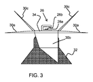
図3は、光分析システムの第1の例をより詳細に示している。 FIG. 3 shows a first example of an optical analysis system in more detail.
光分析システムは、センサモジュール26aおよび基準リフレクタ26bを含む。それらは両方とも回転ブレードに取り付けられている。この例では、それらは、中央ハブ34の上面、すなわち、容器本体に面する面に取り付けられている。センサモジュールは、例えば0.1cm乃至2cm、例えば0.5cm乃至1cmの一定間隔で反射器に面している。これはコンパクトな光学配置を提供する。
The optical analysis system includes a
光分析システムは回転軸上に取り付けられ、システムはブレードと共に回転する。このシステムは、ブレードのブレンド機能を妨げない。 The optical analysis system is mounted on a rotating shaft and the system rotates with the blade. This system does not interfere with the blending function of the blade.
センサモジュールへの電気的接続は、センサモジュールへの相対的な回転を可能にする電気的接続を有する回転軸に沿って通過する。 The electrical connection to the sensor module passes along an axis of rotation having an electrical connection that allows relative rotation to the sensor module.
光は、センサモジュールの光源から、固定された間隔にある混合食品試料に放出される。次いで、センサモジュールの光センサは、反射されたビームを収集し、食品栄養素の内容に関連する吸光度を計算する。 Light is emitted from the light source of the sensor module to the mixed food sample at fixed intervals. The light sensor of the sensor module then collects the reflected beam and calculates the absorbance associated with the food nutrient content.
小さな固定隙間は、小型化を可能にするだけでなく、希釈試料中の光漏れを防止するのにも役立つ。隙間サイズが大きすぎると、光は隙間の側面から散乱することがある。隙間の大きさが小さすぎると、拡散反射方式では小さすぎることがある。 The small fixed gap not only enables miniaturization, but also helps prevent light leakage in the diluted sample. If the gap size is too large, light may be scattered from the sides of the gap. If the size of the gap is too small, the diffuse reflection method may be too small.
図4は、センサモジュール26aがブレード支持体32上に取り付けられ、基準リフレクタ26bが回転ブレードの下面に取り付けられるか、または回転ブレードによって形成される第2の例を示している。
FIG. 4 shows a second example in which the
これは、ブレードの下に光分析システムを提供する。これは、容器内でさえも低く、また、光分析システムに対して何らかの保護を提供する。さらに、この構成は回転電気接続を必要としない。 This provides an optical analysis system under the blade. This is low even within the container and provides some protection for the optical analysis system. Furthermore, this configuration does not require a rotating electrical connection.
図示の例では、基準リフレクタは、中央ハブ34の下面によって形成されている。ブレードは、ブレードアセンブリに取り付けられた構成要素であってもよいし、ブレードアセンブリ自体によって形成されてもよい。
In the illustrated example, the reference reflector is formed by the lower surface of the
この場合、基準リフレクタ26bは、基部に静止したままであるセンサモジュール26aに対して非常に高速(例えば、18,000rpm乃至24,000rpm)に回転することができる。例えば、光学走査は0.1秒乃至1秒かかるので、同期の問題があり得る。このような問題を回避するために、ブレンディングプロセスが終了した時点でサンプルが分析され得る。
In this case, the
この目的のために、(モータ20を制御する)コントローラ22は、ブレンドプロセスの終了時にセンサ機能を実行するようにセンサモジュール26を制御することができる。
For this purpose, the controller 22 (which controls the motor 20) can control the
別の例では、基準リフレクタ26bは、回転ブレードの1つの下側に取り付けられてもよく、または、回転ブレードの1つまたはすべての下側表面によって画定されてもよい。最も低いブレード30bは、この目的のために使用され得る。下向きに指向するブレード30bがない場合、水平ブレードを使用することができる。
In another example, the
この場合、コントローラ22は、ブレンド処理の終了時に基準リフレクタと光センサとを位置合わせするようにモータを制御し、ブレンド処理の終了時に正確に位置合わせされた位置で検知機能を実行するようにしてもよい。
In this case, the
これにより、ブレンドが完了したときの信頼性の高い検出が保証され、1又は複数のブレードに小さいリフレクタのみが必要となる。 This ensures reliable detection when blending is complete and only requires a small reflector on one or more blades.
光分析システムは、容器内に受け取られた食品に関する栄養素情報を得るために使用される。このようにして、ブレンダは、栄養素含有量分析を可能にし、健康管理またはダイエットなどのためにユーザが食事摂取量を制御するのを支援する。 The optical analysis system is used to obtain nutrient information about the food received in the container. In this way, Brenda enables nutrient content analysis and assists the user in controlling dietary intake for health care or dieting and the like.
光分析システムは、近赤外線感知システムまたはラマン分光システム、または反射光学システムの分析に基づく任意の他の光学システムを含むことができる。 The optical analysis system can include a near infrared sensing system or Raman spectroscopy system, or any other optical system based on analysis of a reflective optical system.
白色リフレクタは、例えば、ポリテトラフルオロエチレン(PTFE)または硫酸バリウムから形成される。食品等級基準を満たすために、シリカガラスカバーを使用して、基準リフレクタと混合食品との直接接触を防止することができる。 The white reflector is formed from, for example, polytetrafluoroethylene (PTFE) or barium sulfate. To meet food grade standards, a silica glass cover can be used to prevent direct contact between the reference reflector and the mixed food.
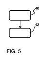
図5は、食品ブレンディング方法を示している。当該方法は、ステップ40において、容器の基部(混合位置にあるとき)に取り付けられたブレードアセンブリを用いて容器内で食品を混合し、ステップ42において、光分析システムを用いて混合食品を分析する。
FIG. 5 shows a food blending method. The method mixes food in the container using a blade assembly attached to the base of the container (when in the mixing position) at
分析は、混合が完了したときに行なわれ、その結果、混合された食品は、光分析システムが配置されている容器の底に沈む。 Analysis is performed when mixing is complete, so that the mixed food sinks to the bottom of the container in which the optical analysis system is located.
本発明を実施する際、図面、開示、及び、添付の請求項の研究から、開示の実施形態に対する他の変形が、当該技術分野における当業者によって、理解及び実施され得る。請求項中、「有する」なる用語は、他の要素又はステップを除外せず、単数形は、複数であることを除外しない。特定の手段が相互に異なる従属項において言及されているという単なる事実は、これらの手段の組み合わせが好適に用いられないということを示すものではない。 In carrying out the invention, other variations to the disclosed embodiments can be understood and implemented by those skilled in the art from studying the drawings, the disclosure, and the appended claims. In the claims, the term “comprising” does not exclude other elements or steps, and the singular does not exclude the presence of a plurality. The mere fact that certain measures are recited in mutually different dependent claims does not indicate that a combination of these measured cannot be used to advantage.
請求項中の任意の参照符号は、本発明の範囲を限定するものとして解釈されるべきではない。 Any reference signs in the claims should not be construed as limiting the scope of the invention.
Claims (15)
使用中、前記容器の基部に取り付けられるように構成されたブレードアセンブリであって、回転ブレード及び非回転ブレード支持体を有する前記ブレードアセンブリと、
光源と反射光を感知するための光センサとを持つセンサモジュール、及び、基準リフレクタを有する光分析システムと、
を有し、
前記センサモジュール及び前記基準リフレクタのうちの少なくとも1つは、前記回転ブレードに取り付けられている、フードブレンダ。 A container for receiving food for mixing;
A blade assembly configured to be attached to a base of the container during use, the blade assembly having a rotating blade and a non-rotating blade support;
A sensor module having a light source and an optical sensor for sensing reflected light, and an optical analysis system having a reference reflector;
Have
A hood blender in which at least one of the sensor module and the reference reflector is attached to the rotating blade.
容器の基部に取り付けられた回転ブレード及び非回転ブレード支持体を有するブレードアセンブリを用いて前記容器内で食品をブレンディングし、
光源と反射光を感知するための光センサとを持つセンサモジュール、及び、基準リフレクタを有する光分析システムを用いて前記ブレンドされる食品を分析し、
前記センサモジュール及び前記基準リフレクタのうちの少なくとも1つが前記回転ブレード上に取り付けられている、方法。 A food blending method,
Blending food in the container using a blade assembly having a rotating blade and a non-rotating blade support attached to the base of the container;
Analyzing the blended food using a light analysis system having a light source and a light sensor for sensing reflected light, and a light analysis system having a reference reflector;
The method wherein at least one of the sensor module and the reference reflector is mounted on the rotating blade.
Applications Claiming Priority (5)
| Application Number | Priority Date | Filing Date | Title |
|---|---|---|---|
| CNPCT/CN2016/091534 | 2016-07-25 | ||
| CN2016091534 | 2016-07-25 | ||
| EP16189675.8 | 2016-09-20 | ||
| EP16189675 | 2016-09-20 | ||
| PCT/EP2017/067891 WO2018019620A1 (en) | 2016-07-25 | 2017-07-14 | Food blender and blending method |
Publications (2)
| Publication Number | Publication Date |
|---|---|
| JP2019518560A JP2019518560A (en) | 2019-07-04 |
| JP6608552B2 true JP6608552B2 (en) | 2019-11-20 |
Family
ID=59388062
Family Applications (1)
| Application Number | Title | Priority Date | Filing Date |
|---|---|---|---|
| JP2018566970A Expired - Fee Related JP6608552B2 (en) | 2016-07-25 | 2017-07-14 | Food blender and blending method |
Country Status (6)
| Country | Link |
|---|---|
| US (1) | US20210289990A1 (en) |
| EP (1) | EP3487368B8 (en) |
| JP (1) | JP6608552B2 (en) |
| CN (1) | CN109475255B (en) |
| RU (1) | RU2720958C1 (en) |
| WO (1) | WO2018019620A1 (en) |
Families Citing this family (5)
| Publication number | Priority date | Publication date | Assignee | Title |
|---|---|---|---|---|
| EP3542687A1 (en) * | 2018-03-22 | 2019-09-25 | Koninklijke Philips N.V. | A food processing apparatus |
| BR112023004888A2 (en) * | 2021-03-31 | 2024-02-06 | Koninklijke Philips Nv | APPLIANCE FOR HOME KITCHEN |
| EP4066703A1 (en) * | 2021-03-31 | 2022-10-05 | Koninklijke Philips N.V. | Domestic kitchen apparatus |
| EP4108146A1 (en) * | 2021-06-22 | 2022-12-28 | trinamiX GmbH | Transflective spectroscopic measurement in blender |
| CN116983891B (en) * | 2023-09-26 | 2023-12-22 | 北京猫猫狗狗科技有限公司 | Pet food mixer and control method thereof |
Family Cites Families (25)
| Publication number | Priority date | Publication date | Assignee | Title |
|---|---|---|---|---|
| JPS5957621A (en) * | 1982-09-27 | 1984-04-03 | 三洋電機株式会社 | Cooking machine |
| JPH0739464A (en) * | 1993-07-28 | 1995-02-10 | Tec Corp | Cooker |
| JPH07270312A (en) * | 1994-02-09 | 1995-10-20 | Satake Eng Co Ltd | Method and device for evaluating taste of cooked rice |
| JPH11225881A (en) * | 1998-02-13 | 1999-08-24 | Matsushita Electric Ind Co Ltd | Cooker |
| FR2791546B1 (en) | 1999-04-02 | 2001-05-04 | Sagem | HOUSEHOLD APPLIANCE FOR FOOD PREPARATION COMPRISING A LID DETECTOR IN THE CLOSED POSITION |
| DE602004003414T2 (en) * | 2003-04-03 | 2007-09-27 | Matsushita Electric Industrial Co., Ltd., Kadoma | Method and device for concentration measurement of a specific component |
| US7477397B2 (en) | 2003-10-08 | 2009-01-13 | Control Development Incorporated | Self-calibrating optical reflectance probe system |
| FR2864762B1 (en) * | 2004-01-06 | 2007-06-01 | Seb Sa | FOOD PREPARING ELECTRICAL APPLIANCE APPARATUS PROVIDED FOR SLEEPING AND REACTIVE |
| US7104184B2 (en) * | 2004-01-13 | 2006-09-12 | Eytan Biderman | Feeding formula appliance |
| ITMI20051224A1 (en) * | 2005-06-29 | 2006-12-30 | De Longhi Spa | MACHINE FOR THE PRODUCTION OF A COFFEE BEVERAGE |
| DE102008040935A1 (en) * | 2008-08-01 | 2010-02-04 | BSH Bosch und Siemens Hausgeräte GmbH | Kitchen appliance with engine speed indicator |
| CN103228189B (en) * | 2010-11-29 | 2016-12-21 | 皇家飞利浦电子股份有限公司 | Method and apparatus for preparing beverages |
| JP5845009B2 (en) * | 2011-07-07 | 2016-01-20 | シャープ株式会社 | Light measurement and analysis device, storage, electromagnetic wave generation device and light measurement and analysis method. |
| WO2013126579A1 (en) * | 2012-02-21 | 2013-08-29 | Minvielle Eugenio | Conditioning system for nutritional substances |
| US20140069838A1 (en) * | 2012-04-16 | 2014-03-13 | Eugenio Minvielle | Nutritional Substance Label System For Adaptive Conditioning |
| US9528972B2 (en) * | 2012-04-16 | 2016-12-27 | Eugenio Minvielle | Dynamic recipe control |
| US9254099B2 (en) * | 2013-05-23 | 2016-02-09 | Medibotics Llc | Smart watch and food-imaging member for monitoring food consumption |
| CN202908493U (en) * | 2012-11-16 | 2013-05-01 | 李文钦 | A cooking and stirring nutritional food conditioning machine |
| US9981234B2 (en) * | 2014-03-20 | 2018-05-29 | Vita-Mix Management Corporation | Container/lid/blender interlock |
| WO2016018750A1 (en) * | 2014-07-30 | 2016-02-04 | North American Robotics Corporation | Automated food processing system and method |
| JP6285047B2 (en) * | 2014-11-07 | 2018-03-07 | テスコム電機株式会社 | Electric cooker |
| CN104406921B (en) * | 2014-12-15 | 2017-02-08 | 中国农业大学 | Optical detection system and optical detection method |
| US10754427B2 (en) * | 2015-03-12 | 2020-08-25 | Vita-Mix Management Corporation | Display system for blending systems |
| CN107232964A (en) * | 2016-03-29 | 2017-10-10 | 九阳股份有限公司 | A kind of cooking apparatus with Analysis of Nutritive Composition function |
| JP2017127691A (en) * | 2017-04-27 | 2017-07-27 | 三菱電機株式会社 | Component detection device and lid provided with component detection device |
-
2017
- 2017-07-14 JP JP2018566970A patent/JP6608552B2/en not_active Expired - Fee Related
- 2017-07-14 CN CN201780046003.0A patent/CN109475255B/en active Active
- 2017-07-14 RU RU2019105058A patent/RU2720958C1/en active
- 2017-07-14 US US16/316,207 patent/US20210289990A1/en not_active Abandoned
- 2017-07-14 EP EP17742998.2A patent/EP3487368B8/en active Active
- 2017-07-14 WO PCT/EP2017/067891 patent/WO2018019620A1/en not_active Ceased
Also Published As
| Publication number | Publication date |
|---|---|
| JP2019518560A (en) | 2019-07-04 |
| US20210289990A1 (en) | 2021-09-23 |
| EP3487368A1 (en) | 2019-05-29 |
| WO2018019620A1 (en) | 2018-02-01 |
| RU2720958C1 (en) | 2020-05-15 |
| CN109475255A (en) | 2019-03-15 |
| EP3487368B8 (en) | 2020-04-15 |
| EP3487368B1 (en) | 2020-03-04 |
| CN109475255B (en) | 2022-05-03 |
Similar Documents
| Publication | Publication Date | Title |
|---|---|---|
| JP6608552B2 (en) | Food blender and blending method | |
| CN107148234B (en) | Electric conditioner | |
| US20190056315A1 (en) | Spectral blender | |
| CN110279321B (en) | Hand mixers and kitchen utensils | |
| EP2421420B1 (en) | Wand attachments for hand-held electric blenders | |
| CN105792717A (en) | Improvements in or relating to vertical mixer installations | |
| US10165894B2 (en) | Automated cooker | |
| EP2220979A1 (en) | Blender for mixing or comminuting foodstuffs and method for operating a blender | |
| EP3599956B1 (en) | A food processing apparatus | |
| CN219108955U (en) | Dining table turntable with orientation sensing function | |
| CN105592762B (en) | Kitchen machine with splash guard | |
| US20070215735A1 (en) | Food processor drive assembly | |
| CN110763304B (en) | Food material processor | |
| CN212393720U (en) | Dough fermenting device and dough mixing machine | |
| JP5533116B2 (en) | Inspection method and apparatus for contents of container | |
| JP2010286182A (en) | Microwave heating device | |
| HK1254795A1 (en) | Electric food processor | |
| HK1242538A1 (en) | Electric food processor |
Legal Events
| Date | Code | Title | Description |
|---|---|---|---|
| A621 | Written request for application examination |
Free format text: JAPANESE INTERMEDIATE CODE: A621 Effective date: 20181220 |
|
| A871 | Explanation of circumstances concerning accelerated examination |
Free format text: JAPANESE INTERMEDIATE CODE: A871 Effective date: 20181220 |
|
| A975 | Report on accelerated examination |
Free format text: JAPANESE INTERMEDIATE CODE: A971005 Effective date: 20190509 |
|
| A131 | Notification of reasons for refusal |
Free format text: JAPANESE INTERMEDIATE CODE: A131 Effective date: 20190704 |
|
| A521 | Request for written amendment filed |
Free format text: JAPANESE INTERMEDIATE CODE: A523 Effective date: 20190925 |
|
| TRDD | Decision of grant or rejection written | ||
| A01 | Written decision to grant a patent or to grant a registration (utility model) |
Free format text: JAPANESE INTERMEDIATE CODE: A01 Effective date: 20191001 |
|
| A61 | First payment of annual fees (during grant procedure) |
Free format text: JAPANESE INTERMEDIATE CODE: A61 Effective date: 20191023 |
|
| R150 | Certificate of patent or registration of utility model |
Ref document number: 6608552 Country of ref document: JP Free format text: JAPANESE INTERMEDIATE CODE: R150 |
|
| LAPS | Cancellation because of no payment of annual fees |