JP6589378B2 - Ophthalmic measuring device - Google Patents
Ophthalmic measuring device Download PDFInfo
- Publication number
- JP6589378B2 JP6589378B2 JP2015109212A JP2015109212A JP6589378B2 JP 6589378 B2 JP6589378 B2 JP 6589378B2 JP 2015109212 A JP2015109212 A JP 2015109212A JP 2015109212 A JP2015109212 A JP 2015109212A JP 6589378 B2 JP6589378 B2 JP 6589378B2
- Authority
- JP
- Japan
- Prior art keywords
- image
- eye
- optical system
- purkinje image
- purkinje
- Prior art date
- Legal status (The legal status is an assumption and is not a legal conclusion. Google has not performed a legal analysis and makes no representation as to the accuracy of the status listed.)
- Active
Links
Images


Description
本開示は、被検眼に関する測定を行う眼科測定装置に関する。 The present disclosure relates to an ophthalmologic measurement apparatus that performs measurement related to an eye to be examined.
被検眼の眼特性の一つとして、角膜後面曲率、角面後面形状等の角膜後面に関する情報が測定される場合がある。角膜後面曲率は、例えば、角膜屈折力の算出に用いられ、その算出結果は、眼内レンズの度数計算に用いられる。従来、角膜後面に関する情報は、シャインプルークカメラ、及び前眼部OCT装置等で撮像される角膜の断面像の解析によって取得されていた。 As one of the eye characteristics of the eye to be examined, there is a case where information related to the corneal surface such as the corneal posterior curvature and the corneal posterior surface shape is measured. The corneal posterior curvature is used, for example, for calculating the corneal refractive power, and the calculation result is used for calculating the power of the intraocular lens. Conventionally, information on the posterior surface of the cornea has been acquired by analyzing a cross-sectional image of the cornea imaged by a Shine-Pluke camera, an anterior ocular segment OCT apparatus, or the like.
上記例示した従来技術の場合、角膜の断面像が必要となる。よって、ユーザーは、必ず、角膜の断面像を撮像する装置を用意しなければならなかった。 In the case of the prior art exemplified above, a cross-sectional image of the cornea is required. Therefore, the user must always prepare a device for capturing a cross-sectional image of the cornea.
なお、シャインプルークカメラにおいて角膜上の複数の経線方向に関して測定する場合、異なる角度での断面像を得るために光学系を回転させる必要があり、装置構成の複雑化を招く。また、前眼部OCTの場合は、干渉光学系及び光スキャナ等を必要とするので、比較的高価である。 Note that when measuring with respect to a plurality of meridian directions on the cornea in a Shine-Pluke camera, it is necessary to rotate the optical system in order to obtain cross-sectional images at different angles, resulting in a complicated apparatus configuration. The anterior segment OCT is relatively expensive because it requires an interference optical system, an optical scanner, and the like.
本開示は、従来技術の問題点に鑑み、簡単な構成で被検眼の角膜後面に関する情報を取得することを目的とする。 In view of the problems of the prior art, the present disclosure aims to obtain information on the posterior corneal surface of the eye to be examined with a simple configuration.
本開示の第1態様に係る眼科測定装置は、被検眼の角膜に向けて指標を投影するための投影光学系と、前記投影光学系によって角膜に投影された指標による第1プルキンエ像と第2プルキンエ像とを撮像素子で撮像する撮像光学系と、装置本体内に設けられた内部固視標を備え、前記被検眼の視線方向を撮像光軸に対して傾斜した方向に誘導可能な固視光学系であって、前記第1プルキンエ像と前記第2プルキンエ像とを分離し、分離された前記第2プルキンエ像に基づく角膜後面に関する情報を得るために用いられる固視光学系と、 前記撮像素子によって撮像された前記第2プルキンエ像であって前記固視光学系によって傾斜された前記被検眼の前記第2プルキンエ像、前記角膜の前面形状に関する情報、および、前記固視光学系によって傾斜された前記被検眼の前記撮像光軸に対する傾斜量に関する情報、に少なくとも基づいて、被検眼の角膜後面に関する情報を取得する演算手段と、を備える。 An ophthalmologic measurement apparatus according to a first aspect of the present disclosure includes a projection optical system for projecting an index toward the cornea of an eye to be examined, a first Purkinje image and a second image using the index projected onto the cornea by the projection optical system. An imaging optical system that captures a Purkinje image with an imaging device and an internal fixation target provided in the apparatus main body, and a fixation that can guide the line of sight of the eye to be examined in a direction inclined with respect to the imaging optical axis An optical system for separating the first Purkinje image and the second Purkinje image, and a fixation optical system used to obtain information on the posterior corneal surface based on the separated second Purkinje image; and The second Purkinje image picked up by an element and tilted by the fixation optical system; the second Purkinje image of the eye to be examined; information on the frontal shape of the cornea; and the fixation optical system. Information about the amount of inclination with respect to the tilted the subject's eye the image pickup optical axis of, at least based on an arithmetic means for obtaining information about the posterior surface of the cornea of the eye, Ru comprising a.
本開示の第2態様に係る眼科測定装置は、被検眼の角膜に向けて指標を投影するための投影光学系と、前記投影光学系によって角膜に投影された指標による第1プルキンエ像と第2プルキンエ像とを撮像素子で撮像する撮像光学系と、被検眼による前記第1プルキンエ像と前記第2プルキンエ像とを分離するため、前記撮像光学系の撮像光軸に対して前記被検眼の視線方向を傾斜させる視線傾斜手段と、前記視線傾斜手段によって傾斜された被検眼の前記第2プルキンエ像を前記撮像素子により撮像し、前記第2プルキンエ像、前記角膜の前面形状に関する情報、および、前記視線傾斜手段によって傾斜された前記被検眼の前記撮像光軸に対する傾斜量に関する情報、に少なくとも基づいて、被検眼の角膜後面に関する情報を取得する制御手段と、を備える。 An ophthalmologic measurement apparatus according to a second aspect of the present disclosure includes a projection optical system for projecting an index toward the cornea of a subject eye, a first Purkinje image and a second image based on the index projected onto the cornea by the projection optical system. In order to separate the first Purkinje image and the second Purkinje image by the imaging eye, and an imaging optical system that captures the Purkinje image with an imaging device, the line of sight of the eye to be inspected with respect to the imaging optical axis of the imaging optical system Line-of-sight tilting means for tilting the direction, the second Purkinje image of the eye to be examined tilted by the line-of-sight tilting means is captured by the imaging device , the second Purkinje image, information on the frontal shape of the cornea, and information about the tilt with respect to the imaging optical axis of the eye to be examined which is inclined by sight tilting means, based at least on the control hand to obtain information about the posterior surface of the cornea of the eye If, Ru equipped with.
本開示によれば、被検眼の角膜後面に関する情報を良好に取得できる。 According to the present disclosure, information related to the corneal posterior surface of the eye to be examined can be acquired favorably.
以下、図面を参照しつつ本開示の典型的な実施形態を説明する。
<装置の概略構成>
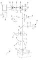
まず、図1を参照して、本実施形態における眼科測定装置1の概略構成について説明する。図1に示す眼科測定装置1は、被検眼Eの角膜前面Ec1,および角膜後面Ec2(図3,図4参照)に関する測定を行う。図1に示すように、眼科測定装置1は、ケラト投影光学系10と、撮像光学系(受光光学系)20と、固視光学系50と、制御部100と、を主に有する。また、本実施形態の眼科測定装置1は、アライメント投影光学系30と、第2測定光学系40と、を有する。なお、これらの光学系は、図示無き筐体に内蔵されている。また、筐体は、周知のアライメント移動機構60の駆動によって、被検眼Eに対して3次元的に移動される。筐体の移動は、例えば、操作部材(例えば、ジョイスティック)に対する検者の操作に応じて行われてもよい。
Hereinafter, exemplary embodiments of the present disclosure will be described with reference to the drawings.
<Schematic configuration of the device>
First, with reference to FIG. 1, a schematic configuration of the ophthalmologic measurement apparatus 1 in the present embodiment will be described. The ophthalmologic measurement apparatus 1 shown in FIG. 1 performs measurements on the corneal front surface Ec1 and the corneal rear surface Ec2 (see FIGS. 3 and 4) of the eye E to be examined. As shown in FIG. 1, the ophthalmologic measurement apparatus 1 mainly includes a kerato projection
固視光学系50は、測定時に、被検眼Eの視線方向を誘導し、被検眼Eを固視させるために用いられる。本実施形態において、固視光学系50は、装置本体内に設けられた内部固視標を有する。つまり、固視光学系50は、装置本体内(換言すれば、筐体内)から、固視標を投影する。また、本実施形態の固視光学系50は、被検眼Eに対して呈示する固視標の位置を切換えることで、被検眼Eの視線方向を、複数の方向に誘導する。なお、固視光学系50の内部固視標は、固視光学系50の光軸L2から離れた位置に設けられていてもよい。
The fixation
固視光学系50は、可視光源(固視灯)51(51a〜51i)、投光レンズ53、可視反射・赤外透過のダイクロイックミラー43、を有する。本実施形態では、内部固視標として、光源(固視灯)51が利用される。光源51から発せられる可視光は、投光レンズ53により平行光束に変換された後、ダイクロイックミラー43により反射され、被検眼Eの眼底に固視標として投影される。ダイクロイックミラー43は、固視光学系50の光軸L2を、撮像光学系20の光軸L1と同軸にする。
The fixation
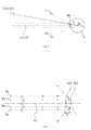
また、本実施形態において、固視光学系50は、複数の光源51a〜51iを固視灯として有する。各光源51a〜51iは、光軸L1(光軸L2)に対して交差(例えば、直交)する方向に関して互いに異なる位置に配置される。光源51a〜51iのうち、制御部100によって選択されたいずれか一つが点灯される。つまり、本実施形態において、固視光学系50は、点灯する固視灯を切換えることで、被検眼Eの視線方向を切換える。
In the present embodiment, the fixation
例えば、光源51aは、光軸L1(光軸L2)近傍に配置された中心固視灯である。固視灯51aが点灯されることによって、固視光学系50は、被検眼Eの視線方向を、光軸L1(つまり、撮像光軸)に沿う方向に誘導する(図3(a)参照)。
For example, the
また、複数の光源51b〜51iは、それぞれ、近傍固視灯である。光源51b〜51iのいずれかが点灯されることによって、固視光学系50は、被検眼Eの視線方向を、光軸L1(撮像光軸)に対して傾斜した方向に誘導する(図4(a)参照)。本実施形態において、近傍固視灯によって誘導される被検眼の視線方向における、光軸L1に対する傾斜量、および傾斜の方向は、角膜中心部の近傍領域が光軸L1上(撮像光軸上)に配置される範囲で設定されていてもよい。
Moreover, each of the
例えば、複数の光源51b〜51iは、光軸L1(光軸L2)を中心とする同一円周上に配置されていてもよい。より詳細には、光源51b〜51iは、被検者から見て、所定角度毎に配置されている。例えば、図2では、光源51b〜51iは、0度、45度、90度、135度、180度、225度、270度、315度の各位置に45度ずつ配置されている。また、複数の光源51b〜51iは、それぞれ、中心固視灯(光源51)に対して(換言すれば、光軸L1に対して)被検眼Eの視軸(視線方向)が所定角度傾斜した関係となる所定位置に配置されている。好ましくは、光軸L1に対して視線方向が5°以上26°以下の角度で傾斜する範囲に、複数の光源51b〜51iが配置されていてもよい。例えば、本実施形態では、それぞれの光源51b〜51iは光軸L1に対して視線方向が13°となる位置に配置されていてもよい。本実施形態においては、この範囲において、後述する第1プルキンエ像Raと第2プルキンエ像Rpとの分離が良好に行われ得る。
For example, the plurality of
ケラト投影光学系10は、角膜Ecに向けてパターン指標(測定指標)を投影(投光)してもよい。図1に示すように、ケラト投影光学系10は、パターン指標を、光軸L1に対して斜め方向から投影してもよい。この場合において、パターン指標が投影される角膜Ecの領域は、中心固視灯51aによって被検眼Eの視線方向が光軸L1に沿う方向へ誘導される場合と、近傍固視灯51b〜51iによって被検眼Eの視線方向が光軸L1に対して傾斜した方向へ誘導される場合と、のいずれの場合においても、角膜中心部の近傍領域となるように、ケラト投影光学系10によるパターン指標の投影位置が定められていてもよい。
The kerato projection
ケラト投影光学系10からのパターン指標は、角膜前面Ec1,および,角膜後面Ec2(角膜裏面)に関する測定に用いられる。例えば、角膜前面Ec1の形状、曲率半径、および屈折力等が角膜前面Ec1に関して測定されてもよい。また、角膜後面Ec2の形状、曲率半径、および屈折力等が、角膜後面Ec2に関して測定されてもよい。更に、角膜前面Ec1に関する測定結果と、角膜後面Ec2に関する測定結果とから、例えば、角膜全体の屈折、角膜厚の分布、角膜における乱視軸角度、収差等が測定されてもよい。
The pattern index from the kerato projection
ケラト投影光学系10は、光源11を有する。光源11が発する光は、例えば、赤外光または可視光であってもよい。ケラト投影光学系10は、光源11から出射される光を、パターン指標として角膜Ecに投影する構成であればよい。なお、パターン指標は、線、又は、複数(3つ以上)の点によって形成された2次元的なパターンであることが好ましい。例えば、連続的、又は、間欠的なリングパターン、同心円状に配置される3つ以上の点指標からなるパターン、点指標が格子状に配列されたドットマトリクス指標、等であってもよい。
The kerato projection
具体例として、図1におけるケラト投影光学系10は、リング光源を光源11として備え、リング状のパターン指標を角膜Ecに投影する。リング光源は、例えば、リング状に形成される光源であってもよいし、リング状に並べられた複数の点光源と、点光源の前に配置されるリング状のパターン開口とを組み合せた構成であってもよい。
As a specific example, the kerato projection
図3(b),図4(b)に示すように、光源11aが投光する光のうち、角膜前面Ec1で反射(および散乱)された光によって、リング状の第1プルキンエ像Raが形成され得る。また、リング光源11が投光する光のうち、角膜後面Ec2で反射(および散乱)された光によって、リング状の第2プルキンエ像Rpが形成され得る。一般に、第2プルキンエ像Rpは、第1プルキンエ像Raに対し、低い輝度となる。
As shown in FIGS. 3B and 4B, the ring-shaped first Purkinje image Ra is formed by light reflected (and scattered) by the cornea front surface Ec1 among the light projected by the light source 11a. Can be done. Moreover, the ring-shaped second Purkinje image Rp can be formed by the light reflected (and scattered) by the corneal rear surface Ec2 among the light projected by the
本実施形態では、光源11は、1つのリング光源を備えるものであるが、互いの半径が異なる2つ以上のリング光源を備えるものであってもよい。この場合、例えば、それぞれのリング光源が、光軸L1を中心とする同心円状に配置されており、また、それぞれのリング光源が、角膜Ecの異なる領域に対してパターン指標を投影してもよい。なお、それぞれのリング光源は、同時に点灯されてもよいし、1つずつ(或いは、一部ずつ)点灯されてもよい。但し、複数のリング光源が同時に点灯される場合は、角膜Ecにおいて指標像の投影位置が、同時に点灯されるリング光源同士で重ならないことが好ましい。
In the present embodiment, the
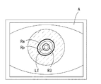
アライメント投影光学系30は、角膜Ecにアライメント視標を投影する。アライメント投影光学系30は、光源31を有する。本実施形態において、光源31は、ケラト投影光学系10の光源11の内側に配置される。光源31は、赤外光を発する投影光源であり、角膜Ecにアライメント指標を投影するために用いられる。角膜Ecに投影されたアライメント指標は、被検眼Eに対する装置の位置合わせ(例えば、自動アライメント、アライメント検出、手動アライメント、等)に用いられる。図2に示すように、本実施形態において、アライメント投影光学系30は、アライメント指標としてリング指標R3を投影する。なお、リング指標像R3は、マイヤーリングを兼用してもよい。また、アライメント投影光学系30の光源31は、前眼部を斜め方向から照明する前眼部照明を兼用する。なお、投影光学系30において、さらに、角膜Ecに平行光を投影する光学系を設け、アライメント投影光学系30による有限光との組合せにより前後のアライメントを行うようにしてもよい。
The alignment projection
撮像光学系20は、撮像素子27を有し、ケラト投影光学系10によって角膜Ecに投影された指標による第1プルキンエ像Raと第2プルキンエ像Rpとを撮像素子27で撮像する。また、図1における撮像光学系20は、撮像素子27の他に、ダイクロイックミラー(ビームスプリッタ)23、対物レンズ24、ミラー25、および、撮像レンズ26を含む。撮像素子27は、例えば、被検眼の前眼部と共役な位置に配置されてもよい。なお、ビームスプリッタ23は、撮像光学系20の光路を第2測定光学系40の光路と分岐させるための光路分岐部材である(詳しくは、後述する)。また、図1の例では、撮像光学系20の光軸L1(撮像光軸)は、中心固視灯51aの投影光軸L2と兼用されている。
The imaging
図1の例において、撮像光学系20は、光軸L1(撮像光軸)に沿う方向から被検眼Eを撮像し、各プルキンエ像Ra,Rpを得る。つまり、中心固視灯51aによって被検眼Eの視線方向が光軸L1に沿う方向へ誘導される場合と、近傍固視灯51b〜51iによって被検眼Eの視線方向が光軸L1に対して傾斜した方向へ誘導される場合と、のいずれにおいても、撮像光学系20は、光軸L1(撮像光軸)に沿う方向から、被検眼Eが撮像される。撮像光学系20は、前眼部正面像を観察するための観察光学系を兼用してもよい。このとき、各プルキンエ像Ra,Rpは、前眼部正面像(以下、前眼部像Aと称す)に含まれる像として、撮像されてもよい。例えば、ケラト投影光学系10による指標の投影と共に、前眼部照明が角膜に照明される場合には、前眼部像Aとして、各プルキンエ像Ra,Rpを含む画像が取得される(図5参照)。
In the example of FIG. 1, the imaging
また、撮像光学系20は、アライメント投影光学系30からの光が照射された被検眼Eを撮像することにより、角膜Ec上に形成されたリング指標像R3を撮像できる(図5参照)。
Further, the imaging
撮像光学系20に関し、ビームスプリッタ23の透過方向には、第2測定光学系40が形成されている。第2測定光学系40は、第2測定光学ユニット41と、ダイクロイックミラー43と、を含む。また、第2測定光学系40は、ビームスプリッタ23を、撮像光学系20と共用する。第2測定ユニット41は、被検者眼に第2の測定光を投光し、その反射光を受光する構成を備える。第2測定ユニット41は、第2の測定光を出射する光源42を有する。
With respect to the imaging
なお、第2測定光学系40としては、例えば、測定光と参照光による干渉光を受光して眼軸長を測定する眼軸長測定光学系、被検者眼眼底に投影された反射光を受光して眼屈折力を測定する眼屈折力測定光学系等であってもよい。
As the second measurement
次に、制御系について説明する。本実施形態において、眼科測定装置1は、装置全体の制御処理と、各種演算等を行う、演算制御部100(以下、制御部と省略する)を有する。制御部100は、CPU101と、ROM102と、RAM103と、を含んでいてもよい。CPU101は、眼科測定装置1に関する各種の処理を実行するための処理装置(プロセッサ)である。ROM102は、制御プログラムおよび固定データ等が格納された、不揮発性の記憶装置である。RAM103は、書き換え可能な揮発性の記憶装置である。RAM103には、例えば、眼科測定装置1による被検眼Eの撮像および測定に用いる一時データが格納される。
Next, the control system will be described. In this embodiment, the ophthalmologic measurement apparatus 1 includes a calculation control unit 100 (hereinafter, abbreviated as a control unit) that performs control processing of the entire apparatus, various calculations, and the like. The
また、本実施形態において、制御部100は、光源11、撮像素子27、光源31、第2測定光学ユニット41、光源51、アライメント移動機構60、モニタ70、操作部80、記憶装置105等に接続される。
In the present embodiment, the
記憶装置105は、書き換え可能な不揮発性の記憶装置である。本実施形態において、記憶装置105には、各種の撮像処理、測定処理等を制御部100に実行させるためのプログラムが、少なくとも格納されていてもよい。また、記憶装置105には、眼科測定装置1によって撮像される前眼部画像が保存されてもよい。
The
撮像素子27から出力される受光信号(撮像信号)は、制御部100によって処理され、モニタ70に表示される。また、本実施形態において、制御部100は、撮像素子27から出力される受光信号に基づいて被検眼Eに対するアライメント状態を検出する。
The light reception signal (imaging signal) output from the
<測定動作>
以上のような構成を備える装置1の動作を説明する。本実施形態では、前眼部の測定に関する装置の動作の一例を、図6のフローチャートを参照して示す。
<Measurement operation>
Operation | movement of the apparatus 1 provided with the above structures is demonstrated. In the present embodiment, an example of the operation of the apparatus relating to the measurement of the anterior segment is shown with reference to the flowchart of FIG.
はじめに、被検眼に対する光学系のアライメントが行われる(S1)。ここでは、制御部100が装置の各部を制御することによって、アライメントが自動的に行われる場合を示す。但し、アライメントは、手動で行われてもよい。また、手動によるアライメント(粗調整)と、自動的なアライメント(微調整)とが組み合わせて行われてもよい。
First, alignment of the optical system with respect to the eye to be examined is performed (S1). Here, a case where the alignment is automatically performed by the
アライメントに際して、制御部100は、中心固視灯51aと、アライメント投影光学系30の光源31と、を点灯させる。また、制御部100は、光源31の点灯に伴って撮像素子27から出力される撮像信号に基づいて、被検眼Eの前眼部像のライブ画像(観察画像)をモニタ70に表示させる。また、制御部100は、レクチルLT(図5参照)を、モニタ70上に電子的に表示させてもよい。ここで、検者は、被検者に、固視標を固視するよう促す。
At the time of alignment, the
その後、制御部100は、光源31によるリング指標R3を、撮像素子27からの撮像信号に基づいて検出する。制御部100は、アライメント移動機構60を、検出結果に基づいて駆動させることによって、リング指標R3の中心にレクチルLTが位置されるように眼科測定装置1の光学系を移動させる。また、制御部100は、撮像素子27からの撮像信号に基づいてアライメント移動機構60を制御することで、装置から角膜頂点までの距離(つまり、作動距離)が、所定の距離となるように、前後方向のアライメントを行う。本実施形態において、制御部100は、アライメント完了後に、光源31を消灯する。
Thereafter, the
次に、制御部100は、パターン指標の投影を開始する(S2)。制御部100は、ケラト投影光学系10が持つ光源11を点灯させる。これによって、角膜Ecには、リング状のパターン指標が投影される。
Next, the
次に、第1撮像処理(S3)が制御部100によって実行される。第1撮像処理(S3)において、制御部100は、固視光学系50によって視線方向が光軸L1に沿う方向に誘導された状態の被検眼Eを、撮像素子27で撮像する。すなわち、視線方向が光軸L1に沿う方向に誘導された状態の被検眼Eにおける第1プルキンエ像Raおよび第2プルキンエ像Rpを含む画像(例えば、前眼部像A)が、撮像素子27から出力される撮像信号に基づいて取得される。取得された各プルキンエ像Ra,Rpを含む画像は、例えば、記憶装置105等に保存されてもよい。
Next, the first imaging process (S3) is executed by the
第1撮像処理(S3)では、視線方向が光軸L1に沿う方向に誘導された状態での撮像が、1回以上行われる。ここでは、説明の便宜上、第1撮像処理(S3)において、1回だけ撮像が行われるものとする(つまり、各プルキンエ像Ra,Rpを含む画像が1枚だけ取得される)。なお、2回以上の撮像が行われる場合については、変容例の項目において後述する。 In the first imaging process (S3), imaging is performed one or more times in a state where the line-of-sight direction is guided in the direction along the optical axis L1. Here, for convenience of explanation, it is assumed that imaging is performed only once in the first imaging process (S3) (that is, only one image including each Purkinje image Ra, Rp is acquired). In addition, the case where imaging is performed twice or more will be described later in the item of modification examples.
また、本実施形態において、被検眼Eの視線方向を光軸L1に沿う方向に誘導するため、制御部100は、中心固視灯である光源51aを予め点灯しておく。例えば、アライメントの段階から引き続き光源51aが点灯されていてもよい。
In the present embodiment, in order to guide the line-of-sight direction of the eye E along the optical axis L1, the
次に、制御部100は、第1指標像検出処理を実行する(S4)。S4の処理において、制御部100は、第1撮像処理(S3)での撮像結果から、第1プルキンエ像Ra、および第2プルキンエ像Rpをそれぞれ検出する。検出処理の結果としては、例えば、第1プルキンエ像Ra,第2プルキンエ像Rpの指標位置情報が取得されてもよい。指標位置情報は、例えば、それぞれの指標像の二次元的な位置情報であってもよい。
Next, the
ここで、S4の検出処理としては、種々の検出処理が採用され得る。例えば、各プルキンエ像Ra,Rpは、画像における輝度情報に基づいて検出されてもよい。例えば、画像上で閾値以上の輝度値を持つ領域を、指標像が形成される領域として検出してもよい。なお、第1プルキンエ像Ra,および第2プルキンエ像Rpは、いずれも経線方向に幅を持っている。そこで、角膜Ecの各経線において各指標像が形成される領域のうち、輝度のピーク(最大値または極大値)の位置、中央の位置等が、各経線上における指標像の位置を示す検出結果として、取得されてもよい。 Here, various detection processes may be employed as the detection process of S4. For example, each Purkinje image Ra, Rp may be detected based on luminance information in the image. For example, an area having a luminance value equal to or higher than a threshold value on the image may be detected as an area where an index image is formed. The first Purkinje image Ra and the second Purkinje image Rp both have a width in the meridian direction. Therefore, among the regions where each index image is formed in each meridian of the cornea Ec, the detection result indicating the position of the index image on each meridian, such as the position of the luminance peak (maximum value or maximum value), the center position, etc. As may be obtained.
また、制御部100は、例えば、第1プルキンエ像Raと第2プルキンエ像Rpとの特性を利用することで、第1プルキンエ像Raと第2プルキンエ像Rpとを区別して検出し得る。例えば、第2プルキンエ像Rpに対し、第1プルキンエ像Raは、より明るい像(高い輝度値を持つ)であるという特性を利用し得る。例えば、値の異なる2種類の閾値(第1閾値、第2閾値)を使用し、第1プルキンエ像Raと第2プルキンエ像Rpとを区別するようにしてもよい。また、第2プルキンエ像Rpに対し、第1プルキンエ像Raは、概して光軸L1のより外側に形成されるという特性を利用し得る。例えば、制御部100は、より外側の輝線を、第1プルキンエ像Raとして検出し、その内側に形成される輝線を、第2プルキンエ像Rpとして検出するようにしてもよい。勿論、各プルキンエ像Ra,Rpの検出方法は、必ずしもこれに限られるものではない。制御部100は、例えば、RAM102、および記憶装置105等のいずれかに検出結果を記憶する。
For example, the
但し、上記のような検出手法を用いたとしても、第2プルキンエ像Rpの検出ができない場合がある。例えば、第2プルキンエ像Rpと第1プルキンエ像Raとが画像上で重なっている場合には、第2プルキンエ像Rpの検出は困難である。ここで、被検眼Eの角膜形状が、検出を難しくする要因となりうる。 However, even if the above detection method is used, the second Purkinje image Rp may not be detected. For example, when the second Purkinje image Rp and the first Purkinje image Ra overlap on the image, it is difficult to detect the second Purkinje image Rp. Here, the cornea shape of the eye E can be a factor that makes detection difficult.
例えば、一般に、角膜前面Ec1の頂点と、角膜後面Ec2の頂点とは、視軸と交差する方向に関してズレて形成されている傾向がある。これにより、被検眼の視線方向を光軸L1に沿う方向に誘導した状態での撮像結果において、第1プルキンエ像Raに対し、第2プルキンエ像Rpが一方向に偏って形成されてしまい、第1プルキンエ像Raと第2プルキンエ像Rpとが部分的に重なってしまう場合がありうる。なお、ここでは、光軸L1に視線方向が誘導された被検眼Eの角膜前面Ec1,角膜後面Ec2のそれぞれにおいて、法線が光軸L1に沿う方向を向く位置を、頂点と称している。 For example, generally, the vertex of the corneal front surface Ec1 and the vertex of the corneal posterior surface Ec2 tend to be formed with a deviation in the direction intersecting the visual axis. Thereby, in the imaging result in a state in which the line-of-sight direction of the eye to be examined is guided in the direction along the optical axis L1, the second Purkinje image Rp is formed in one direction with respect to the first Purkinje image Ra. There may be a case where the first Purkinje image Ra and the second Purkinje image Rp partially overlap. Here, in each of the corneal front surface Ec1 and the corneal posterior surface Ec2 of the eye E in which the line-of-sight direction is guided to the optical axis L1, the position where the normal line faces in the direction along the optical axis L1 is referred to as a vertex.
また、例えば、LASIK手術によって角膜の中心部が削られた眼において、角膜前面Ec1の曲率と、角膜後面Ec2の曲率とが近い値となることがありうる。このような眼においては、第1プルキンエ像Raと第2プルキンエ像Rpとの少なくとも一部が、重なってしまう場合があり得る。 In addition, for example, in an eye in which the central portion of the cornea has been cut by LASIK surgery, the curvature of the corneal front surface Ec1 and the curvature of the corneal posterior surface Ec2 may be close to each other. In such an eye, at least a part of the first Purkinje image Ra and the second Purkinje image Rp may overlap.
その他に、例えば、角膜形状の個人差、角膜形状異常等によっても、第2プルキンエ像Rpの検出ができない場合が考えられる。第2プルキンエ像Rpが適正に検出できない場合、制御部100は、例えば、検出エラーを示す情報を、第2プルキンエ像Rpの検出結果として記憶してもよい。なお、少なくとも、第1プルキンエ像Raに関しては、第1指標像検出処理(S4)によって検出可能である。そこで、第2プルキンエ像Rpが検出できない場合でも、第1プルキンエ像Raの検出結果については、記憶装置105等に記憶させるようにしてもよい。
In addition, there may be a case where the second Purkinje image Rp cannot be detected due to individual differences in corneal shape, abnormal corneal shape, or the like. When the second Purkinje image Rp cannot be detected properly, the
次に、制御部100は、第2プルキンエ像Rpが、第1指標像検出処理(S4)によって検出できるか否かを判定する(S5)。第2プルキンエ像Rpが検出できないと判定される場合は(S5:No)、第2撮像処理(S6)が実行される。一方、第2プルキンエ像Rpが検出できると判定される場合は(S5:Yes)、第2撮像処理(S6)をスキップして、前眼部情報取得処理(S10)を実行する。
Next, the
第2撮像処理(S6)において、制御部100は、固視光学系50によって視線方向が光軸L1に沿う方向に誘導された状態の被検眼Eを、撮像素子27で撮像する。すなわち、視線方向が光軸L1に対して傾斜した被検眼Eにおける各プルキンエ像Ra,Rpを含む画像(例えば、前眼部像A)が、撮像素子27から出力される撮像信号に基づいて取得される。第2撮像処理(S6)において取得された画像は、例えば、記憶装置105等に保存されてもよい。また、制御部100は、画像とともに、光軸L1に対する視線方向の傾斜量、および傾斜方向に関する傾斜量情報を、記憶装置105に記憶してもよい。傾斜量情報としては、近傍固視灯51b〜51iによって誘導された視線方向の傾斜量を特定するための情報であればよく、撮像時に点灯されていた固視灯を特定する情報であってもよいし、固視灯の位置に基づいて所期される傾斜量、および傾斜方向の設計値等であってもよい。また、被検眼Eにおける実際の傾斜量、および傾斜方向が測定され、その測定値が利用されてもよい。
In the second imaging process (S6), the
本実施形態では、第2撮像処理(S6)による撮像に際して、被検眼による前記第1プルキンエ像と前記第2プルキンエ像とを分離するため、制御部100が固視光学系50を制御し、光軸L1に対して被検眼Eの視線方向を傾斜させる。より詳細には、制御部100は、第1撮像処理(S3)の段階で少なくとも点灯されていた中心固視灯51aを消灯し、近傍固視灯51b〜51iのいずれか1つを点灯させる。
In the present embodiment, the
第2撮像処理(S6)では、光軸L1に対して視線方向が傾斜した状態での各プルキンエ像Ra,Rpの撮像が、1回以上行われる。ここでは、説明の便宜上、第2撮像処理(S6)において、1回だけ撮像が行われるものとする(つまり、各プルキンエ像Ra,Rpを含む画像が1枚だけ取得される)。なお、2回以上の撮像が行われる場合については、変容例の項目において後述する。 In the second imaging process (S6), the Purkinje images Ra and Rp are captured once or more in a state where the line-of-sight direction is inclined with respect to the optical axis L1. Here, for convenience of explanation, it is assumed that imaging is performed only once in the second imaging process (S6) (that is, only one image including each Purkinje image Ra, Rp is acquired). In addition, the case where imaging is performed twice or more will be described later in the item of modification examples.
ある方向(例えば、光軸L1に沿う方向)に誘導された状態では、第2プルキンエ像Rpが他の指標像(主に、第1プルキンエ像Ra)と画像上で重なってしまい、第2プルキンエ像Rpの検出ができない場合がある。この場合であっても、視線方向を別方向に誘導することによって、第2プルキンエ像Rpを他の指標像から分離できる場合がある。例えば、上述したように、角膜前面Ec1の曲率と、角膜後面Ec2の曲率とが、近い値である場合には、視線方向が光軸L1に沿う方向に誘導された状態では、第2プルキンエ像Rpが第1プルキンエ像Raと、重なってしまう。しかし、視線方向が光軸L1に対して傾斜することによって、角膜前面Ec1におけるパターン指標像の投影位置と、角膜後面Ec2におけるパターン指標像の投影位置とが、それぞれ異なる変位量にて変位する。その結果、撮像光学系20で撮像される第2プルキンエ像Rpと第1プルキンエ像Raとが分離され得る。結果、第2プルキンエ像Rpが検出されやすい画像が得られる。
In a state of being guided in a certain direction (for example, a direction along the optical axis L1), the second Purkinje image Rp overlaps with another index image (mainly the first Purkinje image Ra) on the image, and the second Purkinje image is obtained. The image Rp may not be detected. Even in this case, the second Purkinje image Rp may be separated from other index images by guiding the line-of-sight direction to another direction. For example, as described above, when the curvature of the corneal front surface Ec1 and the curvature of the corneal rear surface Ec2 are close to each other, the second Purkinje image is in a state in which the line-of-sight direction is guided in the direction along the optical axis L1. Rp overlaps with the first Purkinje image Ra. However, when the line-of-sight direction is inclined with respect to the optical axis L1, the projection position of the pattern index image on the front surface of the cornea Ec1 and the projection position of the pattern index image on the rear surface of the cornea Ec2 are displaced by different amounts of displacement. As a result, the second Purkinje image Rp and the first Purkinje image Ra captured by the imaging
次に、制御部100は、第2指標像検出処理を実行する(S7)。S7の処理において、制御部100は、第2撮像処理(S6)での撮像結果から、第1プルキンエ像Ra、および第2プルキンエ像Rpをそれぞれ検出する。プルキンエ像の検出方法は、例えば、第1指標像検出処理(S3)と同様の処理であってもよく、詳細な説明は省略する。
Next, the
次に、制御部100は、第2プルキンエ像Rpが、第2指標像検出処理(S7)によって検出できるか否かを判定する(S8)。第2プルキンエ像Rpが検出できないと判定される場合は(S8:No)、たとえば、更に、点灯する固視灯を、別の近傍固視灯51b〜51iに切り替え(S9)、第2撮像処理(S6)、第2指標像検出処理(S7)を、繰り返し実行してもよい。また、全ての近傍固視灯51b〜51iに関して第2指標像検出処理を実行したものの、いずれにおいても第2プルキンエ像Rpが検出されない場合には、測定エラー等を示す情報をモニタ70に表示させて、フローチャートの処理を終了してもよい(図示せず)。一方、第2プルキンエ像Rpが検出できると判定される場合は、前眼部情報取得処理(S10)を実行する。
Next, the
本実施形態の前眼部情報取得処理(S10)では、第2プルキンエ像Rpの検出結果に基づく角膜後面Ec2に関する情報が、少なくとも取得される。更に、本実施形態では、角膜前面Ec1に関する情報についても取得される。 In the anterior segment information acquisition process (S10) of the present embodiment, at least information on the corneal posterior surface Ec2 based on the detection result of the second Purkinje image Rp is acquired. Furthermore, in the present embodiment, information regarding the corneal front surface Ec1 is also acquired.
ここで、前眼部情報取得処理(S10)の一例について説明する。本実施形態では、まず、制御部100は、角膜前面Ec1の形状を求める。角膜前面Ec1の形状は、例えば、第1指標像検出処理(S4),または、第2指標像検出処理(S7)で得られた第1プルキンエ像Raの指標位置情報に基づいて導出できる。例えば、第1プルキンエ像Raに基づく光線追跡シミュレーションによって、角膜前面形状を求めてもよい。この場合、例えば、作動距離の近傍位置に置かれる角膜前面Ec1のモデルを想定する。本実施形態において、角膜前面Ec1のモデルは、球面近似したモデルである。但し、角膜また、非球面(例えば、楕円球面、放物面等)で近似したモデルであってもよい。この角膜前面Ec1のモデルの曲率を変化させることで、撮像面上における第1プルキンエ像Raの指標位置から、撮像光学系20の光路を逆に辿って角膜前面Ec1へ投影され、角膜前面Ec1で反射されることによって、光源11に到る光線を満足するような角膜前面Ec1の形状の条件(ここでは、曲率半径)を求める。例えば、光源11から、第1プルキンエ像Raまでの光線を示す光線行列を用いて、上記シミュレーションが行われてもよい。この光線行列では、光線行列における入口又は出口の面の一方における光線高さに、第1プルキンエ像Raの像高さが代入され、他方における光線高さ、および光線の傾きに、光源11に基づく既定値が代入される。このようにして、角膜前面Ec1の曲率半径を得ることができる。
Here, an example of the anterior segment information acquisition process (S10) will be described. In the present embodiment, first, the
ここで、上記のシミュレーションで想定される角膜前面Ec1のモデルの位置には、第1プルキンエ像Raの撮像時における視線方向の傾斜量、および傾斜方向が考慮される。つまり、第1指標像検出処理(S4)によって検出された第1プルキンエ像Raから角膜前面Ec1の形状を得る場合、視線方向が正面方向を向く(つまり、光軸L1に沿う)角膜前面Ec1のモデルを想定して、上記の光線追跡シミュレーションが行われる(図3(b)参照)。一方、第2指標像検出処理(S7)によって検出された第1プルキンエ像Raから角膜前面Ec1の形状を得る場合、撮像時における視線方向の傾斜量および傾斜方向で視軸が傾いた角膜前面Ec1のモデルを想定して、上記の光線追跡シミュレーションが行われる(図4(b)参照)。角膜前面Ec1のモデルの位置は、例えば、眼の旋回中心から角膜Ecにおける基準点(例えば、角膜頂点)までの長さと、視線方向の傾斜量、および傾斜方向とによって、規定し得る。ここで、旋回中心から角膜Ecにおける基準点までの長さは、例えば、人眼の平均値等の既定値が使用されてもよいし、被検眼Eにおける実際の眼寸法の測定値に基づく値であってもよい。また、傾斜量および傾斜方向には、第2撮像処理(S6)において各プルキンエ像Ra,Rpと共に記憶された傾斜量情報によって示される値が使用されてもよい。
また、例えば、角膜前面Ec1の曲率半径は、第1指標像検出処理(S4),または第2指標像検出処理(S7)によって検出された第1プルキンエ像Raの指標位置情報に基づいて、計算によって求めてもよい。具体的には、角膜曲率半径r1を第1プルキンエ像Raの像高さ(例えば、光軸L1が角膜の中心部を通過する条件下では、画像上の光軸L1の位置(例えば、画像中心)から第1プルキンエ像Raまでの距離)に基づいて求める手法がある。具体的な手法については、例えば、本出願人による特開2003―111727号公報を参考にされたい。
また、例えば、角膜前面Ec1の曲率半径は、第1指標像検出処理(S4),または第2指標像検出処理(S7)によって検出された第1プルキンエ像Raの指標位置情報に基づいて、計算によって求めてもよい。具体的には、角膜曲率半径r1を第1プルキンエ像Raの像高さ(例えば、光軸L1が角膜の中心部を通過する条件下では、画像上の光軸L1の位置(例えば、画像中心)から第1プルキンエ像Raまでの距離)に基づいて求める手法がある。具体的な手法については、例えば、本出願人による特開2003―111727号公報を参考にされたい。
Here, the amount of inclination in the line-of-sight direction and the inclination direction at the time of capturing the first Purkinje image Ra are considered in the position of the model of the corneal front surface Ec1 assumed in the above simulation. That is, when the shape of the corneal front surface Ec1 is obtained from the first Purkinje image Ra detected by the first index image detection process (S4), the line-of-sight direction is the front direction (that is, along the optical axis L1) of the corneal front surface Ec1. The ray tracing simulation described above is performed assuming a model (see FIG. 3B). On the other hand, when the shape of the corneal front surface Ec1 is obtained from the first Purkinje image Ra detected by the second index image detection process (S7), the corneal front surface Ec1 whose visual axis is inclined in the sight line direction and the inclination direction during imaging is obtained. The above ray tracing simulation is performed assuming the above model (see FIG. 4B). The position of the model of the corneal front surface Ec1 can be defined by, for example, the length from the center of eye rotation to the reference point (for example, the corneal apex) in the cornea Ec, the amount of inclination in the line-of-sight direction, and the inclination direction. Here, as the length from the turning center to the reference point in the cornea Ec, for example, a predetermined value such as an average value of the human eye may be used, or a value based on a measured value of an actual eye dimension in the eye E to be examined. It may be. For the tilt amount and the tilt direction, values indicated by the tilt amount information stored together with the Purkinje images Ra and Rp in the second imaging process (S6) may be used.
For example, the radius of curvature of the corneal front surface Ec1 is calculated based on the index position information of the first Purkinje image Ra detected by the first index image detection process (S4) or the second index image detection process (S7). You may ask for. Specifically, the corneal curvature radius r1 is set to the image height of the first Purkinje image Ra (for example, the position of the optical axis L1 on the image (for example, the image center under the condition that the optical axis L1 passes through the center of the cornea) ) To the first Purkinje image Ra). For a specific method, for example, refer to Japanese Patent Application Laid-Open No. 2003-111727 by the present applicant.
For example, the radius of curvature of the corneal front surface Ec1 is calculated based on the index position information of the first Purkinje image Ra detected by the first index image detection process (S4) or the second index image detection process (S7). You may ask for. Specifically, the corneal curvature radius r1 is set to the image height of the first Purkinje image Ra (for example, the position of the optical axis L1 on the image (for example, the image center under the condition that the optical axis L1 passes through the center of the cornea) ) To the first Purkinje image Ra). For a specific method, for example, refer to Japanese Patent Application Laid-Open No. 2003-111727 by the present applicant.
次に、先に求めた角膜前面Ec1の形状と、第2プルキンエ像Rpの指標位置情報とに基づいて、角膜後面Ec2の形状を導出する。例えば、第2プルキンエ像Rpに基づく光線追跡シミュレーションによって、角膜後面Ec2の形状を求めてもよい。この場合、先に求めた曲率半径による角膜前面Ec1のモデルと、角膜後面Ec2のモデルと、を想定する。本実施形態において、角膜前面Ec2のモデルは、例えば、球面近似したモデルである。但し。非球面(例えば、楕円球面、放物面等)で近似したモデルであってもよい。 Next, the shape of the corneal posterior surface Ec2 is derived based on the previously determined shape of the corneal front surface Ec1 and the index position information of the second Purkinje image Rp. For example, the shape of the corneal posterior surface Ec2 may be obtained by a ray tracing simulation based on the second Purkinje image Rp. In this case, a model of the anterior corneal surface Ec1 and a model of the posterior corneal surface Ec2 are assumed based on the previously obtained radius of curvature. In the present embodiment, the model of the corneal front surface Ec2 is, for example, a spherical approximation model. However. A model approximated by an aspherical surface (for example, an elliptical spherical surface, a paraboloid, etc.) may be used.
角膜後面Ec2のモデルは、角膜前面Ec1のモデルに対し、角膜Ecの基準位置(本実施形態では、角膜中心)において角膜厚d分だけ眼の旋回中心側に配置される。角膜厚dは、人眼の平均値等の既定値が用いられてもよいし、実際の被検眼Eの角膜厚が用いられてもよい。例えば、超音波測定方式等の公知のパキ測定によって得られた値を用いてもよい。なお、第2測定光学系として角膜厚測定光学系を設け、その測定結果が角膜厚dとして利用されてもよい。 The model of the corneal posterior surface Ec2 is arranged closer to the center of eye rotation by the corneal thickness d at the reference position of the cornea Ec (in this embodiment, the corneal center) than the model of the corneal front surface Ec1. As the corneal thickness d, a predetermined value such as an average value of the human eye may be used, or the actual corneal thickness of the eye E may be used. For example, a value obtained by publicly known patch measurement such as an ultrasonic measurement method may be used. Note that a corneal thickness measurement optical system may be provided as the second measurement optical system, and the measurement result may be used as the corneal thickness d.
また、角膜後面Ec2のモデルは、その頂点位置が、角膜前面Ec1のモデルの頂点位置に対して視軸と交差する方向に関してずれて配置されてもよい。例えば、所定角度だけずれて配置されてもよい。 Further, the model of the corneal posterior surface Ec2 may be arranged such that the vertex position thereof is shifted with respect to the direction intersecting the visual axis with respect to the vertex position of the model of the corneal front surface Ec1. For example, it may be arranged so as to be shifted by a predetermined angle.
制御部100は、角膜後面Ec2のモデルの曲率を変化させることで、撮像面上における第2プルキンエ像Rpの指標位置から、撮像光学系20の光路を逆に辿って角膜前面Ec1を介して角膜後面Ec2で反射され、光源11に到る光線を満足するような角膜後面Ec2の形状の条件(ここでは、角膜後面Ec2の曲率半径)を求める。勿論、制御部100は、角膜前面Ec1を光線が通過する際の屈折を考慮して、条件を求める。角膜Ecの屈折率には、例えば、人眼の平均値等の既定値(n≒1.376等)が使用されてもよい。このシミュレーションの結果として、角膜後面Ec2の曲率半径を得ることができる。
The
なお、上記のシミュレーションにて想定される角膜前面Ec1のモデル,および角膜後面Ec2のモデルの位置には、各プルキンエ像Ra,Rpの撮像時における視線方向の傾斜量、および傾斜方向が考慮される。例えば、第2指標像検出処理(S7)で検出された第2プルキンエ像Rpに基づいて角膜後面Ec2の形状を得る場合、撮像時における視線方向の傾斜量、および傾斜方向に応じて、眼の旋回中心を中心として傾いた角膜前面Ec1のモデル,および角膜後面Ec2のモデルを想定して、上記の光線追跡シミュレーションが行われる(図4(b)参照)。また、例えば、角膜後面Ec2の曲率半径は、第1指標像検出処理(S4),または第2指標像検出処理(S7)によって検出された第2プルキンエ像Rpの指標位置情報に基づいて、計算によって求めてもよい。なお、本実施形態では、角膜前面Ec1に関する情報と角膜後面Ec2に関する情報とを求める手法として、まず角膜前面Ec1に関する情報が取得され、取得された情報を用いて角膜後面Ec2の形状を求める手法が利用された。しかし、必ずしもこれに限られるものではない。例えば、光線追跡シミュレーション等によって、角膜前面Ec1に関する情報と角膜後面Ec2とを同時に取得することも可能である。 Note that the amount of inclination in the line-of-sight direction and the inclination direction at the time of imaging of the Purkinje images Ra and Rp are taken into consideration in the positions of the model of the corneal front surface Ec1 and the model of the corneal rear surface Ec2 assumed in the above simulation. . For example, when the shape of the corneal posterior surface Ec2 is obtained based on the second Purkinje image Rp detected in the second index image detection process (S7), the amount of the eye is determined according to the amount of inclination in the line-of-sight direction and the inclination direction during imaging. The above ray tracing simulation is performed assuming a model of the corneal front surface Ec1 and a model of the corneal rear surface Ec2 tilted around the turning center (see FIG. 4B). For example, the radius of curvature of the corneal posterior surface Ec2 is calculated based on the index position information of the second Purkinje image Rp detected by the first index image detection process (S4) or the second index image detection process (S7). You may ask for. In the present embodiment, as a method for obtaining information related to the corneal anterior surface Ec1 and information related to the corneal posterior surface Ec2, first, information relating to the corneal anterior surface Ec1 is acquired, and using the acquired information, a method for determining the shape of the corneal posterior surface Ec2 is used. It was used. However, it is not necessarily limited to this. For example, it is possible to simultaneously acquire information on the corneal front surface Ec1 and the corneal rear surface Ec2 by ray tracing simulation or the like.
このようにして得た、角膜前面Ec1の形状と、角膜後面Ec2の形状とに基づいて、制御部100は、角膜厚情報、角膜Ecの屈折力情報等を、求めることができる。
Based on the shape of the corneal front surface Ec1 and the shape of the corneal posterior surface Ec2 thus obtained, the
例えば、制御部100は、角膜厚情報の一例として、特定の経線方向における角膜Ecの厚み分布を示す情報を取得しても良い。1つの経線方向における角膜Ecの厚み分布は、例えば、1つの経線方向における角膜前面Ec1の曲率半径、および角膜後面Ec2の曲率半径r1と、基準の角膜厚dの値と、を用いて求めることができる。また、制御部100は、複数の経線方向における角膜全体の厚み分布に基づいて、角膜全体の厚み分布を示す情報を取得してもよい。
For example, the
また、角膜Ecの屈折力情報等として、例えば、角膜全体の屈折力を求めることができる。この場合、例えば、角膜前面Ec1のパワー情報(例えば、パワー及び/又は、S,C,Aの各値)と、角膜後面Ec2のパワー情報(例えば、パワー及び/又は、S,C,Aの各値)とを、プルキンエ像から求めることができる。本実施形態において、S,C,Aの各値は、例えば、角膜Ecに形成されるリング像を楕円近似したときの強主経線方向及び弱主経線方向における角膜曲率の値、および、強主経線および弱主経線の軸角度等から求めることができる。そして、パワーベクトル法を用いて、角膜前面Ec1のパワーと、角膜後面Ec2のパワーとの合成値から、角膜全体の屈折力を得ることができる。なお、角膜全体の屈折力の導出は、上記の手法に限られるものではない。例えば、光線追跡的に屈折力が求められてもよい。 Further, as the refractive power information of the cornea Ec, for example, the refractive power of the entire cornea can be obtained. In this case, for example, power information (for example, power and / or values of S, C, and A) of the corneal front surface Ec1 and power information (for example, power and / or S, C, and A of the corneal rear surface Ec2). Each value) can be obtained from the Purkinje image. In the present embodiment, the values of S, C, and A are, for example, values of the corneal curvature in the strong main meridian direction and the weak main meridian direction when the ring image formed on the cornea Ec is approximated to an ellipse, and the strong principal It can be obtained from the axis angles of meridians and weak main meridians. Then, using the power vector method, the refractive power of the entire cornea can be obtained from the combined value of the power of the corneal front surface Ec1 and the power of the corneal rear surface Ec2. The derivation of the refractive power of the entire cornea is not limited to the above method. For example, the refractive power may be obtained in a ray tracing manner.
以上説明したように、本実施形態の眼科測定装置1は、固視光学系50によって視線方向が光軸L1に対して傾斜した被検眼Eを撮像素子27で撮像する。その結果、光軸L1に沿う方向へ視線方向を誘導した場合には、第2プルキンエ像Rpを特定(例えば、画像検出)しにくい被検眼Eであっても、第2プルキンエ像Rpを、他の指標像(例えば、第1プルキンエ像Ra等)と分離できる。結果、第2プルキンエ像に基づいて角膜後面Ec2に関する情報を取得する可能性を高めることができる。
As described above, the ophthalmologic measurement apparatus 1 according to the present embodiment images the eye E with the
また、本実施形態では、制御部100が固視光学系50を制御することで、光軸L1に対する傾斜量がそれぞれ異なる複数の方向に、被検眼Eの視線方向が誘導され、それぞれの視線方向で、第2プルキンエ像Rpを含む画像が撮像される。複数の視線方向における撮像が行われることで、他の指標像から分離された第2プルキンエ像Rpを得る可能性が高まる。結果、角膜後面Ec2に関する情報を取得できる可能性が、一層改善される。
In the present embodiment, the
なお、角膜後面Ec2の曲率を求める場合、被検眼Eの角膜厚を用いた算出が好ましい。そこで、第2測定光学系として角膜厚測定光学系を設けることで、必ずしも他の装置を用いる必要がなくなる。角膜厚測定光学系は、例えば、特開2012−143492号に記載の構成が用いられる。 In addition, when calculating | requiring the curvature of the cornea back surface Ec2, calculation using the corneal thickness of the eye E to be examined is preferable. Therefore, by providing the corneal thickness measurement optical system as the second measurement optical system, it is not always necessary to use another device. For the corneal thickness measurement optical system, for example, the configuration described in JP 2012-143492 A is used.
この場合であっても、角膜厚測定光学系は、角膜上の少なくとも1点の角膜厚が測定できればよく、回転機構を持つシャインプルーフカメラや、二次元スキャンを要する前眼部OCT等の複雑の光学系を設ける必要は必ずしもなくなる。 Even in this case, the corneal thickness measurement optical system only needs to measure the corneal thickness of at least one point on the cornea, and is complicated such as a shine-proof camera having a rotation mechanism and an anterior segment OCT that requires two-dimensional scanning. It is not always necessary to provide an optical system.
また、上記実施形態では、角膜後面Ecに関する情報として、角膜Ecの合成パワーが得られる。ここで、シャインプルーフカメラや、前眼部OCT等で撮像される断面画像に基づいて角膜全体のパワーを演算することもできる。しかし、本実施形態のように、第2プルキンエ像Rpに基づいて演算した場合の方が、正確なパワーを取得しやすい。従って、眼科測定装置1で得られたパワーは、例えば、被検眼に対し適正なパワーのIOLを選定する場合等に役立つ。 Moreover, in the said embodiment, the synthetic | combination power of the cornea Ec is obtained as information regarding the cornea back surface Ec. Here, the power of the entire cornea can also be calculated based on a cross-sectional image captured by a shine-proof camera, an anterior ocular segment OCT, or the like. However, as in this embodiment, it is easier to obtain accurate power when the calculation is performed based on the second Purkinje image Rp. Therefore, the power obtained by the ophthalmologic measurement apparatus 1 is useful, for example, when selecting an IOL having an appropriate power for the eye to be examined.
なお、一般に、被検眼Eへ投光された光束が前眼部で反射されることによって形成されるプルキンエ像としては、第1プルキンエ像Raと第2プルキンエ像Rpの他に、水晶体の前面反射による第3プルキンエ像、および水晶体の後面反射による第4プルキンエ像が知られている。上記説明した通り、眼科測定装置1が、固視標によって被検眼Eの視線方向を光軸L1に対して傾斜させることは、第1プルキンエ像Raと第2プルキンエ像Rpとを分離するうえで有用であるが、更に、第3プルキンエ像および第4プルキンエ像の少なくともいずれかと、第2プルキンエ像Rpとを分離するうえでも有用である。つまり、本実施形態の眼科測定装置1は、第3プルキンエ像および第4プルキンエ像とも良好に分離された第2プルキンエ像Rpを取得することができ、その結果から、角膜後面に関する情報を良好に取得できる。
<変形例>
以上、実施形態に基づき説明したが、本開示は、上記実施形態に限定されることなく、様々な変形が可能である。
In general, as a Purkinje image formed by reflecting a light beam projected onto the eye E to be examined by the anterior eye part, in addition to the first Purkinje image Ra and the second Purkinje image Rp, the front reflection of the crystalline lens. And the fourth Purkinje image by reflection of the back surface of the crystalline lens are known. As described above, when the ophthalmic measuring apparatus 1 tilts the line-of-sight direction of the eye E with respect to the optical axis L1 by the fixation target, the first Purkinje image Ra and the second Purkinje image Rp are separated. Although useful, it is also useful for separating at least one of the third Purkinje image and the fourth Purkinje image from the second Purkinje image Rp. That is, the ophthalmologic measurement apparatus 1 of the present embodiment can obtain the second Purkinje image Rp that is well separated from both the third Purkinje image and the fourth Purkinje image, and from the result, information on the corneal posterior surface is favorably obtained. You can get it.
<Modification>
As mentioned above, although demonstrated based on embodiment, this indication is not limited to the said embodiment, A various deformation | transformation is possible.
例えば、第2プルキンエ像が正立像であるのに対し、第4プルキンエ像は倒立像である。光軸L1に対し対称なパターン指標を投影した場合、第2プルキンエ像の近くに第4プルキンエ像が形成される場合がある。その結果、第2プルキンエ像を、第4プルキンエ像と区別して特定することが重要となる。 For example, the second Purkinje image is an upright image, while the fourth Purkinje image is an inverted image. When a pattern index symmetrical to the optical axis L1 is projected, a fourth Purkinje image may be formed near the second Purkinje image. As a result, it is important to distinguish the second Purkinje image from the fourth Purkinje image.
これに対し、例えば、角膜Ecの経線に対して非対称な指標パターンが投影されるように、ケラト投影光学系10(投光光学系の一例)が構成されてもよい。そのうえで、指標光束の正立反射像から第2プルキンエ像が検出されるように、第2プルキンエ像検出処理(例えば、S9の処理)が構成されてもよい。角膜Ecの経線に対して非対称な投影される構成としては、例えば、各々のリング光源11a,11bが、部分的に(または、間欠的に)点灯される態様であってもよい。また、リング光源11a,11bが、角膜Ecの経線に対して非対称に配置される複数の点光源等によって代替される態様であってもよい。この場合、第2プルキンエ像を正立像とした場合、第4プルキンエ像は、倒立像として得られる。よって、制御部100は、光軸L1と各像との位置関係に基づいて、第2プルキンエ像と、第4プルキンエ像とを、区別して検出しうる。
On the other hand, for example, the kerato projection optical system 10 (an example of a light projection optical system) may be configured such that an asymmetric index pattern is projected with respect to the meridian of the cornea Ec. In addition, the second Purkinje image detection process (for example, the process of S9) may be configured such that the second Purkinje image is detected from the erect reflected image of the index light beam. As a configuration in which the projection is asymmetric with respect to the meridian of the cornea Ec, for example, the ring light sources 11a and 11b may be partially (or intermittently) lit. Further, the ring light sources 11a and 11b may be replaced by a plurality of point light sources and the like arranged asymmetrically with respect to the meridian of the cornea Ec. In this case, when the second Purkinje image is an erect image, the fourth Purkinje image is obtained as an inverted image. Therefore, the
また、上記施形態では、角膜Ecの基準位置での角膜厚として、角膜中心部での角膜厚が用いられる場合を説明したが、必ずしもこれに限定されるものではなく、基準位置での角膜厚は、角膜中心から離れた領域での角膜厚が用いられてもよい。 Moreover, although the said embodiment demonstrated the case where the corneal thickness in the cornea center part was used as a corneal thickness in the reference | standard position of the cornea Ec, it is not necessarily limited to this, The corneal thickness in a reference | standard position is used. The corneal thickness in a region away from the center of the cornea may be used.
上記実施形態では、第1撮像処理(S2),第2撮像処理(S6)の各処理において、制御部100が、各プルキンエ像Ra,Rpを含む画像(例えば、前眼部像A)を被検眼の視線方向毎に1枚ずつ撮像するものとして説明した。しかし、必ずしもこれに限られるものではなく、視線方向毎に複数枚ずつ撮像をおこなってもよい。
In the above embodiment, in each process of the first imaging process (S2) and the second imaging process (S6), the
1つの視線方向に関して2回以上の撮像を行う場合、撮像毎に、異なる撮像条件が設定されてもよい。ここでいう撮像条件は、主に、角膜Ecに形成される指標像の明るさに関する条件であってもよい。このような条件は、例えば、光源11から出力される光束の光量、および、撮像素子27におけるゲイン等であってもよい。一般に、第2プルキンエ像Rpは、第1プルキンエ像Raに比べて低い輝度で形成される。このため、例えば、第1プルキンエ像Raと、第2プルキンエ像Rpと、の両方を、一枚の画像からは検出することが難しい場合があり得る。これに対し、いくつかの撮像条件で撮像を行うことで、第1プルキンエ像Ra検出用の画像と、第2プルキンエ像Rp検出用の画像とを、別々の画像として取得してもよい。
When performing imaging twice or more with respect to one gaze direction, different imaging conditions may be set for each imaging. The imaging conditions here may mainly be conditions relating to the brightness of the index image formed on the cornea Ec. Such conditions may be, for example, the light amount of the light beam output from the
また、例えば、パターン指標を投影する光源を複数備える構成にあっては、1つの視線方向に関して2回以上の撮像を行う場合に、撮像毎に点灯する光源を切換えるようにしてもよい。この場合、角膜Ecに形成される指標像同士が重なり合ってしまうことが、各画像において抑制される。つまり、第1プルキンエ像と第2プルキンエ像との重なり合い、第1プルキンエ像同士の重なり合い、第2プルキンエ像同士の重なり合いが、それぞれ抑制される。結果、各画像からの指標像の検出が容易になる。 Further, for example, in a configuration including a plurality of light sources for projecting the pattern index, the light source that is turned on for each imaging may be switched when imaging is performed twice or more in one gaze direction. In this case, the index images formed on the cornea Ec are prevented from overlapping in each image. That is, the overlap between the first Purkinje image and the second Purkinje image, the overlap between the first Purkinje images, and the overlap between the second Purkinje images are suppressed. As a result, the index image can be easily detected from each image.
また、上記実施形態において、固視光学系50によって誘導する被検眼Eの視線方向は、制御部100によって自動的に設定された。しかし、例えば、固視光学系50によって誘導する被検眼Eの視線方向を、検者が手動で設定してもよい。このとき、例えば、撮像光学系20で撮像される第1プルキンエ像Raおよび第2プルキンエ像Rpをモニタ50に表示してもよい。検者は、モニタ50に表示される各プルキンエ像Ra,Rpの分離の程度を確認しながら、操作部80を介して、視線方向の変更を装置に指示する。制御部100は、操作部80から入力される信号に基づいて固視光学系50を制御して、固視光学系50によって誘導する被検眼Eの視線方向を変更する。更に、制御部100は調整後の視線方向に基づいて、角膜前面Ec1に関する情報、および角膜後面Ec2に関する情報を取得する。
In the embodiment described above, the line-of-sight direction of the eye E guided by the fixation
また、上記実施形態において、固視光学系50は、光軸L1(光軸L2)と交差する方向に複数の固視灯51a〜51iを備え、点灯する固視灯51a〜51iが制御部100によって切換えられることで、被検眼Eの視線方向を誘導する方向を変更する。しかし、固視光学系50は、必ずしもこれに限られるものではない。例えば、固視光学系50は、複数の固視灯51a〜51iに替えて、固視標(固視灯)と、固視標と被検眼との相対位置を光軸L1と交差する方向に変位させる駆動機構と、を、備えてもよい。この場合、駆動機構は、装置本体内(筐体内)で、固視標を移動させる駆動機構であってもよい。また、固視標を装置本体内で移動させずに、装置本体(筐体)と、被検眼Eとの相対位置を変更するための機構であってもよい。例えば、装置本体を、XY方向(上下左右方向)に移動させる駆動機構(例えば、図1のアライメント移動機構60)であってもよいし、被検者の顔を支持する顎台65(図1参照)をXY方向に移動させる駆動機構であってもよい。また、例えば、眼科測定装置1は、固視灯51a〜51iに替えて、ディスプレイを有してもよい。制御部100によって、ディスプレイ上の固視目標(例えば、図形、文字等)が移動されることで、被検眼Eの視線方向を誘導してもよい。
In the above-described embodiment, the fixation
また、上記実施形態において、固視光学系50によって被検眼の視線方向を光軸L1に対して傾斜した状態に誘導する場合において、眼科測定装置1は、視線方向の傾斜量を調整できる構成を備えていてもよい。例えば、固視光学系50によって、光軸L1(光軸L2)を中心とする各半径方向の異なる位置で、固視標が呈示されてもよい。この場合において、固視光学系50は、近傍固視灯51b〜51iとは半径の異なる第2の近傍固視灯を、更に備える構成であってもよいし、固視標と被検眼との相対位置を光軸L1(光軸L2)と交差する方向に変位させる駆動機構を備えた構成であってもよいし、固視灯51を上記のディスプレイに置き換えた構成であってもよい。例えば、制御部100が、固視光学系50を制御し、固視標の呈示位置を光軸L1(光軸L2)から離れた位置にて、光軸L1(光軸L2)を中心とする半径方向に切り替えることで、被検眼Eの視線方向の傾斜量が調整される。これにより、第2プルキンエ像Rpを、他の指標像とより好適に分離できる可能性が高まる。このような視線方向の傾斜量調整は、例えば、検者の操作に基づいて実行されてもよい。このとき、例えば、撮像光学系20で撮像される第1プルキンエ像Raおよび第2プルキンエ像Rpをモニタ50に表示してもよい。検者は、モニタ50に表示される各プルキンエ像Ra,Rpの分離の程度を確認しながら、操作部80を介して、傾斜量の変更を装置に指示する。制御部100は、操作部80から入力される信号に基づいて、被検眼Eにおける視線方向の傾斜量を調整し、更に、調整後の傾斜量に基づいて、角膜前面Ec1に関する情報、および角膜後面Ec2に関する情報を取得する。
In the above embodiment, when the fixation
また、上記実施形態では、第2プルキンエ像の検出が、撮像素子27によって撮像される画像そのものから行われる場合について説明した。しかし、撮像素子27によって撮像された画像を、更に加工等した画像から、第2プルキンエ像Rpが検出されてもよい。例えば、複数枚の画像を撮像したうえで、これらの画像の加算画像を生成し、加算画像に対して第2プルキンエ像Rpの検出処理が行われるようにしても良い。複数枚の画像が加算されることで、明確な第2プルキンエ像を含む加算画像が得られるので、第2プルキンエ像Rpの検出が良好に行われやすくなる。なお、第1プルキンエ像Raについても、加算画像から検出されてもよい。
In the above embodiment, the case where the second Purkinje image is detected from the image itself captured by the
また、第2プルキンエ像Rpを検出するための画像の撮像時においては、ケラト投影光学系10以外の光学系(例えば、アライメント投影光学系30、第2測定光学系42)等によって被検眼Eに照射される光を抑制することが好ましい。なお、このとき、第2プルキンエ像が撮像されればよく、前眼部の各部位については、画像内で確認できないものであってもよい。つまり、第2プルキンエ像Rpを検出するための画像は、必ずしも前眼部像に限られるものではない。
Further, at the time of capturing an image for detecting the second Purkinje image Rp, the eye E is examined by an optical system other than the kerato projection optical system 10 (for example, the alignment projection
10 ケラト投影光学系
20 撮像光学系
27 撮像素子
30 アライメント投影光学系
50 固視光学系
100 制御部
Ra 第1プルキンエ像
Rp 第2プルキンエ像
DESCRIPTION OF
Claims (2)
前記投影光学系によって角膜に投影された指標による第1プルキンエ像と第2プルキンエ像とを撮像素子で撮像する撮像光学系と、
装置本体内に設けられた内部固視標を備え、前記被検眼の視線方向を撮像光軸に対して傾斜した方向に誘導可能な固視光学系であって、前記第1プルキンエ像と前記第2プルキンエ像とを分離し、分離された前記第2プルキンエ像に基づく角膜後面に関する情報を得るために用いられる固視光学系と、
前記撮像素子によって撮像された前記第2プルキンエ像であって前記固視光学系によって傾斜された前記被検眼の前記第2プルキンエ像、前記角膜の前面形状に関する情報、および、前記固視光学系によって傾斜された前記被検眼の前記撮像光軸に対する傾斜量に関する情報、に少なくとも基づいて、被検眼の角膜後面に関する情報を取得する演算手段と、を備える眼科測定装置。 A projection optical system for projecting an index toward the cornea of the eye to be examined;
An imaging optical system that captures an image of the first Purkinje image and the second Purkinje image based on the index projected onto the cornea by the projection optical system;
A fixation optical system comprising an internal fixation target provided in the apparatus main body and capable of guiding the line-of-sight direction of the eye to be examined in a direction inclined with respect to the imaging optical axis , wherein the first Purkinje image and the first eye A fixation optical system used to separate two Purkinje images and obtain information on the posterior corneal surface based on the separated second Purkinje images ;
By the second Purkinje image captured by the imaging device, the second Purkinje image of the eye to be examined tilted by the fixation optical system, information on the frontal shape of the cornea, and the fixation optical system information about the amount of inclination with respect to the tilted the subject's eye the image pickup optical axis of, at least based on an arithmetic means for obtaining information about the posterior surface of the cornea of the eye, Ru comprising an ophthalmic measurement apparatus.
前記投影光学系によって角膜に投影された指標による第1プルキンエ像と第2プルキンエ像とを撮像素子で撮像する撮像光学系と、
被検眼による前記第1プルキンエ像と前記第2プルキンエ像とを分離するため、前記撮像光学系の撮像光軸に対して前記被検眼の視線方向を傾斜させる視線傾斜手段と、
前記視線傾斜手段によって傾斜された被検眼の前記第2プルキンエ像を前記撮像素子により撮像し、前記第2プルキンエ像、前記角膜の前面形状に関する情報、および、前記視線傾斜手段によって傾斜された前記被検眼の前記撮像光軸に対する傾斜量に関する情報、に少なくとも基づいて、被検眼の角膜後面に関する情報を取得する制御手段と、
を備える眼科測定装置。 A projection optical system for projecting an index toward the cornea of the eye to be examined;
An imaging optical system that captures an image of the first Purkinje image and the second Purkinje image based on the index projected onto the cornea by the projection optical system;
Line-of-sight tilting means for tilting the line-of-sight direction of the eye to be imaged with respect to the imaging optical axis of the imaging optical system in order to separate the first Purkinje image and the second Purkinje image by the eye to be examined;
The second Purkinje image of the eye to be examined tilted by the line-of-sight tilting means is picked up by the imaging device , and the second Purkinje image, information on the frontal shape of the cornea, and the subject tilted by the line-of-sight tilting means. Control means for acquiring information relating to the posterior corneal surface of the eye to be examined, based at least on information relating to the amount of inclination of the optometry to the imaging optical axis
Ophthalmology measuring device Ru equipped with.
Priority Applications (1)
| Application Number | Priority Date | Filing Date | Title |
|---|---|---|---|
| JP2015109212A JP6589378B2 (en) | 2015-05-28 | 2015-05-28 | Ophthalmic measuring device |
Applications Claiming Priority (1)
| Application Number | Priority Date | Filing Date | Title |
|---|---|---|---|
| JP2015109212A JP6589378B2 (en) | 2015-05-28 | 2015-05-28 | Ophthalmic measuring device |
Publications (3)
| Publication Number | Publication Date |
|---|---|
| JP2016220860A JP2016220860A (en) | 2016-12-28 |
| JP2016220860A5 JP2016220860A5 (en) | 2018-06-21 |
| JP6589378B2 true JP6589378B2 (en) | 2019-10-16 |
Family
ID=57746757
Family Applications (1)
| Application Number | Title | Priority Date | Filing Date |
|---|---|---|---|
| JP2015109212A Active JP6589378B2 (en) | 2015-05-28 | 2015-05-28 | Ophthalmic measuring device |
Country Status (1)
| Country | Link |
|---|---|
| JP (1) | JP6589378B2 (en) |
Family Cites Families (12)
| Publication number | Priority date | Publication date | Assignee | Title |
|---|---|---|---|---|
| JPS5928945A (en) * | 1982-08-09 | 1984-02-15 | キヤノン株式会社 | Apparatus for measuring cornea shape |
| JPS6257534A (en) * | 1985-09-06 | 1987-03-13 | キヤノン株式会社 | Ophthalmic measuring apparatus |
| JPH07128579A (en) * | 1993-10-29 | 1995-05-19 | Canon Inc | Detecting method for light of sight, detecting means for line of sight and video device having detecting means for line of sight |
| US5475452A (en) * | 1994-02-24 | 1995-12-12 | Keravision, Inc. | Device and method for mapping objects |
| JP2002200045A (en) * | 2000-10-24 | 2002-07-16 | Topcon Corp | Ophthalmic instrument |
| JP4349937B2 (en) * | 2004-03-01 | 2009-10-21 | 株式会社ニデック | Ophthalmic equipment |
| JP4859479B2 (en) * | 2006-02-20 | 2012-01-25 | 株式会社トーメーコーポレーション | Keratometer |
| EP2187802B1 (en) * | 2007-08-21 | 2017-11-01 | Visionix Ltd. | Multifunctional ophthalmic measurement system and corresponding method |
| EP2268192B8 (en) * | 2008-04-17 | 2022-01-19 | Stichting VUmc | Apparatus for corneal shape analysis and method for determining a corneal thickness |
| JP5566711B2 (en) * | 2010-01-29 | 2014-08-06 | 株式会社トプコン | Ophthalmic equipment |
| EP2583618B1 (en) * | 2011-10-22 | 2017-12-06 | Alcon Pharmaceuticals Ltd. | Apparatus for monitoring one or more parameters of the eye |
| JP2014079494A (en) * | 2012-10-18 | 2014-05-08 | Canon Inc | Ophthalmologic apparatus and ophthalmologic control method, and program |
-
2015
- 2015-05-28 JP JP2015109212A patent/JP6589378B2/en active Active
Also Published As
| Publication number | Publication date |
|---|---|
| JP2016220860A (en) | 2016-12-28 |
Similar Documents
| Publication | Publication Date | Title |
|---|---|---|
| JP6349701B2 (en) | Ophthalmic measuring device | |
| EP2415393B1 (en) | Ophthalmic apparatus | |
| US11013400B2 (en) | Ophthalmic apparatus | |
| JP6471466B2 (en) | Ophthalmic apparatus and processing program used therefor | |
| JP6736356B2 (en) | Ophthalmic equipment | |
| JP6238552B2 (en) | Ophthalmic apparatus, control method for ophthalmic apparatus, and program | |
| JP7283391B2 (en) | eye refractive power measuring device | |
| JP6772412B2 (en) | Ophthalmic equipment | |
| JP6898712B2 (en) | Ophthalmic equipment | |
| EP3150111B1 (en) | Ophthalmic apparatus and control program for the ophthalmic apparatus | |
| US20210298599A1 (en) | Ophthalmic apparatus | |
| JP7367509B2 (en) | Ophthalmology measurement equipment, ophthalmology measurement system, and ophthalmology measurement program | |
| JP6589378B2 (en) | Ophthalmic measuring device | |
| JP7009273B2 (en) | Ophthalmic device and its corneal shape measurement method | |
| JP6662412B2 (en) | Ophthalmic measurement device | |
| JP6769092B2 (en) | Ophthalmic equipment | |
| JP7459491B2 (en) | Ophthalmology measuring device | |
| JP6823339B2 (en) | Ophthalmic equipment | |
| WO2023145638A1 (en) | Ophthalmic device and ophthalmic program | |
| JP6430770B2 (en) | Ophthalmic equipment | |
| JP7248770B2 (en) | ophthalmic equipment | |
| WO2022209991A1 (en) | Ophthalmologic device | |
| JP7187769B2 (en) | Ophthalmic device and ophthalmic device control program | |
| JP2023050574A (en) | Ophthalmologic measurement device | |
| JP2004073395A (en) | Ophthalmoscopic equipment |
Legal Events
| Date | Code | Title | Description |
|---|---|---|---|
| A521 | Request for written amendment filed |
Free format text: JAPANESE INTERMEDIATE CODE: A523 Effective date: 20180508 |
|
| A621 | Written request for application examination |
Free format text: JAPANESE INTERMEDIATE CODE: A621 Effective date: 20180508 |
|
| A977 | Report on retrieval |
Free format text: JAPANESE INTERMEDIATE CODE: A971007 Effective date: 20181214 |
|
| A131 | Notification of reasons for refusal |
Free format text: JAPANESE INTERMEDIATE CODE: A131 Effective date: 20190115 |
|
| A521 | Request for written amendment filed |
Free format text: JAPANESE INTERMEDIATE CODE: A523 Effective date: 20190315 |
|
| TRDD | Decision of grant or rejection written | ||
| A01 | Written decision to grant a patent or to grant a registration (utility model) |
Free format text: JAPANESE INTERMEDIATE CODE: A01 Effective date: 20190820 |
|
| A61 | First payment of annual fees (during grant procedure) |
Free format text: JAPANESE INTERMEDIATE CODE: A61 Effective date: 20190902 |
|
| R150 | Certificate of patent or registration of utility model |
Ref document number: 6589378 Country of ref document: JP Free format text: JAPANESE INTERMEDIATE CODE: R150 |
|
| R250 | Receipt of annual fees |
Free format text: JAPANESE INTERMEDIATE CODE: R250 |
|
| R250 | Receipt of annual fees |
Free format text: JAPANESE INTERMEDIATE CODE: R250 |