JP6579850B2 - Actuator and vehicle door opening / closing actuator - Google Patents

Actuator and vehicle door opening / closing actuator Download PDF

Info

Publication number
JP6579850B2
JP6579850B2 JP2015152706A JP2015152706A JP6579850B2 JP 6579850 B2 JP6579850 B2 JP 6579850B2 JP 2015152706 A JP2015152706 A JP 2015152706A JP 2015152706 A JP2015152706 A JP 2015152706A JP 6579850 B2 JP6579850 B2 JP 6579850B2
Authority
JP
Japan
Prior art keywords
housing
actuator
coil spring
gear
shaft
Prior art date
Legal status (The legal status is an assumption and is not a legal conclusion. Google has not performed a legal analysis and makes no representation as to the accuracy of the status listed.)
Expired - Fee Related
Application number
JP2015152706A
Other languages
Japanese (ja)
Other versions
JP2017032071A (en
Inventor
貴史 瀧澤
貴史 瀧澤
義隆 関根
義隆 関根
博志 楠
博志 楠
新 谷口
新 谷口
文哉 杉戸
文哉 杉戸
重喜 太田
重喜 太田
吉隆 浦野
吉隆 浦野
里司 永元
里司 永元
亮 後閑
亮 後閑
Current Assignee (The listed assignees may be inaccurate. Google has not performed a legal analysis and makes no representation or warranty as to the accuracy of the list.)
Mitsuba Corp
Original Assignee
Mitsuba Corp
Priority date (The priority date is an assumption and is not a legal conclusion. Google has not performed a legal analysis and makes no representation as to the accuracy of the date listed.)
Filing date
Publication date
Application filed by Mitsuba Corp filed Critical Mitsuba Corp
Priority to JP2015152706A priority Critical patent/JP6579850B2/en
Publication of JP2017032071A publication Critical patent/JP2017032071A/en
Application granted granted Critical
Publication of JP6579850B2 publication Critical patent/JP6579850B2/en
Expired - Fee Related legal-status Critical Current
Anticipated expiration legal-status Critical

Links

Images

Description

本発明は、例えば自動車のテールゲート等のドアを開閉するために用いられるアクチュエータおよび車両ドア開閉用アクチュエータに関するものである。   The present invention relates to an actuator used for opening and closing a door such as a tailgate of an automobile and a vehicle door opening and closing actuator.

従来から、車両用ドア開閉装置として、車体側の開口部の周囲と、この開口部に開閉可能に設けられたテールゲート(バックドア)との間に、軸方向に伸縮駆動されることによってテールゲートを開閉動作させるアクチュエータ(支持部材)を設ける構成が知られている(例えば、特許文献1参照)。   Conventionally, as a door opening and closing device for a vehicle, the tail is driven by extending and contracting in the axial direction between the periphery of the opening on the vehicle body side and a tailgate (back door) that can be opened and closed in the opening. A configuration is known in which an actuator (support member) that opens and closes a gate is provided (see, for example, Patent Document 1).

このようなアクチュエータは、筒状の第1ハウジングと、第1ハウジングよりも大径で第1ハウジングが挿入された第2ハウジングと、第1ハウジング内に設けられたモータと、モータに減速機を介して連結され、モータと同軸状に配置されたネジスピンドルと、第2ハウジングに固定され、ネジスピンドルに螺合したスピンドルナットと、第2ハウジング内に収容されて第1ハウジングと第2ハウジングとを伸長方向に付勢する圧縮コイルバネと、を備えている。モータと減速機は、それぞれ第1ハウジング内に別々に設けられている。そして、モータハウジングに絞り加工を施して、モータの回転軸を回転自在に支持するための軸受を設けている。一方、減速機は、モータの回転軸とネジスピンドルとによって回転自在に支持されている。   Such an actuator includes a cylindrical first housing, a second housing having a larger diameter than the first housing and the first housing inserted therein, a motor provided in the first housing, and a speed reducer for the motor. A screw spindle which is connected to the motor and is coaxially arranged, a spindle nut fixed to the second housing and screwed to the screw spindle, and a first housing and a second housing housed in the second housing. And a compression coil spring that urges in the extending direction. The motor and the speed reducer are provided separately in the first housing. The motor housing is subjected to a drawing process to provide a bearing for rotatably supporting the rotating shaft of the motor. On the other hand, the speed reducer is rotatably supported by a rotating shaft of a motor and a screw spindle.

このような構成のもと、アクチュエータは、モータを回転駆動させると、モータの出力軸の回転が減速機を介してネジスピンドルに伝達され、ネジスピンドルが回転する。ネジスピンドルの回転により、ネジスピンドルに螺合したスピンドルナットがネジスピンドルの軸方向に移動する。これにより、第1ハウジングに対して第2ハウジングが出没し、アクチュエータが伸縮する。   Under such a configuration, when the actuator rotates the motor, the rotation of the output shaft of the motor is transmitted to the screw spindle via the speed reducer, and the screw spindle rotates. Due to the rotation of the screw spindle, the spindle nut screwed to the screw spindle moves in the axial direction of the screw spindle. As a result, the second housing moves in and out of the first housing, and the actuator expands and contracts.

特開2014−100956号公報Japanese Patent Application Laid-Open No. 2014-100566

ところで、上記したようなアクチュエータは、第1ハウジングに対して第2ハウジングを進退させるために、これら第1ハウジングと第2ハウジングとの間に若干の隙間を形成する必要があるが、この隙間から雨水や塵埃等が侵入するおそれがある。アクチュエータ内に雨水や塵埃等が侵入し、さらにモータに付着してしまうと、アクチュエータの耐久性や作動に影響が出てしまうという課題がある。   By the way, the actuator as described above needs to form a slight gap between the first housing and the second housing in order to move the second housing forward and backward with respect to the first housing. There is a risk that rainwater, dust, etc. may enter. If rainwater or dust enters the actuator and adheres to the motor, there is a problem that the durability and operation of the actuator are affected.

そこで、この発明は、上述した事情に鑑みてなされたものであって、モータに対する防塵、防水性を高め、耐久性を向上できるとともに、作動の信頼性を高めることができるアクチュエータおよび車両ドア開閉用アクチュエータを提供するものである。   Accordingly, the present invention has been made in view of the above-described circumstances, and can improve the dustproof and waterproof properties of the motor, improve the durability, and improve the operation reliability. An actuator is provided.

上記の課題を解決するために、本発明に係るアクチュエータは、筒状の第一ハウジングと、該第一ハウジングに対して出没可能に設けられた筒状の第二ハウジングと、前記第一ハウジングに内蔵されたモータと、前記モータの回転軸の回転力を受けて回転駆動される駆動軸と、前記第一ハウジング内に設けられ、前記回転軸および前記駆動軸の何れか一方のみを回転自在に支持する軸受を保持する軸受ホルダと、前記第二ハウジングに固定され、前記駆動軸の回転にともなって前記駆動軸の軸方向に沿って移動することで、前記第一ハウジングに対して前記第二ハウジングを出没させる従動部材と、前記第一ハウジングおよび前記第二ハウジング内に設けられ、前記第一ハウジングに対して前記第二ハウジングを突出させる方向の付勢力を付与するコイルスプリングと、前記第一ハウジングおよび前記第二ハウジング内に設けられ、前記コイルスプリングの内側に配置される筒状のガイド部材と、前記第一ハウジングの内周面に円環状の内壁を設けるとともに、該内壁と前記軸受ホルダとにより、前記モータへの侵入物の侵入を防止するためのシール部材を挟持し、前記ガイド部材の前記軸受ホルダ側の端部に、前記コイルスプリングと前記シール部材との間に介在するフランジ部を形成し、該フランジ部を前記内壁として機能させると共に、前記コイルスプリングにより、前記フランジ部を前記軸受ホルダに向かって押圧することを特徴とする。 In order to solve the above problems, an actuator according to the present invention includes a cylindrical first housing, a cylindrical second housing provided so as to be able to protrude and retract with respect to the first housing, and the first housing. A built-in motor, a drive shaft that is rotationally driven in response to the rotational force of the rotation shaft of the motor, and the first housing are provided so that only one of the rotation shaft and the drive shaft can be rotated. A bearing holder that holds a bearing to be supported, and is fixed to the second housing, and moves along the axial direction of the drive shaft with the rotation of the drive shaft. A follower member for projecting and retracting the housing, and a biasing force provided in the first housing and the second housing, in a direction for projecting the second housing to the first housing. A coil spring provided in the first housing and the second housing and disposed inside the coil spring, and an annular inner wall is provided on the inner peripheral surface of the first housing. The inner wall and the bearing holder sandwich a seal member for preventing the intruder from entering the motor, and the coil spring and the seal member are disposed at the end of the guide member on the bearing holder side. And a flange portion that functions as the inner wall, and the flange portion is pressed against the bearing holder by the coil spring.

このように構成することで、例えば、前記第一ハウジングと前記第二ハウジングとの隙間から水や塵埃が侵入した場合であっても、シール部材によって、モータに水や塵埃が付着してしまうことを防止できる。しかも、内壁と軸受ホルダとによりシール部材を挟持するので、シール部材に対して内壁および軸受ホルダを密着させることができるので、モータに水や塵埃が付着してしまうことを確実に防止できる。このため、アクチュエータの耐久性を向上できるとともに、作動の信頼性を高めることができる。
また、第一ハウジングに内壁を形成するような加工が必要無くなり、第一ハウジングの加工コストを低減できる。また、ガイド部材に形成されたフランジ部を利用し、このフランジ部にシール部材を密着させるので、アクチュエータの組立作業も容易化できる。さらに、コイルスプリングのバネ力を利用してシール部材側にフランジ部を押圧させることにより、シール部材に対するフランジ部および軸受ホルダの密着性を高めることができる。
また、ガイド部材によって、圧縮時におけるコイルスプリングの圧縮方向に交差する方向の座屈を防止できる。コイルスプリングの押圧力は、フランジ部を介してシール部材に伝達されるため、コイルスプリングの押圧力がシール部材に均等に作用する。このため、シール部材に対するフランジ部および軸受ホルダの密着性をさらに高めることができる。
With this configuration, for example, even when water or dust enters from a gap between the first housing and the second housing, the seal member causes water or dust to adhere to the motor. Can be prevented. In addition, since the seal member is sandwiched between the inner wall and the bearing holder, the inner wall and the bearing holder can be brought into close contact with the seal member, so that it is possible to reliably prevent water and dust from adhering to the motor. For this reason, the durability of the actuator can be improved and the operation reliability can be increased.
Moreover, the process which forms an inner wall in a 1st housing becomes unnecessary, and the process cost of a 1st housing can be reduced. Moreover, since the flange part formed in the guide member is utilized and the seal member is brought into close contact with the flange part, the assembly work of the actuator can be facilitated. Furthermore, by using the spring force of the coil spring to press the flange portion toward the seal member, it is possible to improve the adhesion between the flange portion and the bearing holder with respect to the seal member.
Further, the guide member can prevent buckling in the direction intersecting the compression direction of the coil spring during compression. Since the pressing force of the coil spring is transmitted to the seal member via the flange portion, the pressing force of the coil spring acts equally on the seal member. For this reason, the adhesiveness of the flange part with respect to a sealing member and a bearing holder can further be improved.

本発明に係るアクチュエータは、前記第二ハウジングの内部において、前記コイルスプリングの内側に位置して前記ガイド部材の前記軸受ホルダとは反対側の端部内に挿入されるとともに、前記従動部材を保持する第二ガイド部材をさらに備えることを特徴とする。   The actuator according to the present invention is located inside the coil spring inside the second housing and is inserted into the end of the guide member opposite to the bearing holder, and holds the driven member. A second guide member is further provided.

このように構成することで、ガイド部材と第二ガイド部材の2つのガイド部材により、コイルスプリングの全長をガイドすることができる。また、第二ガイド部材によって、圧縮時におけるコイルスプリングの圧縮方向に交差する方向の座屈を防止できる。このため、コイルスプリングの押圧力がシール部材にさらに均等に作用する。この結果、シール部材に対するフランジ部および軸受ホルダの密着性をさらに高めることができる。
さらに、第二ガイド部材が従動部材を保持することで、従動部材を保持するために他の部品等を備える必要がなく、部品点数を減少できる。
By comprising in this way, the full length of a coil spring can be guided with two guide members, a guide member and a 2nd guide member. Further, the second guide member can prevent buckling in the direction intersecting the compression direction of the coil spring during compression. For this reason, the pressing force of the coil spring acts more evenly on the seal member. As a result, the adhesion between the flange portion and the bearing holder with respect to the seal member can be further enhanced.
Furthermore, since the second guide member holds the driven member, it is not necessary to provide other parts to hold the driven member, and the number of parts can be reduced.

本発明に係るアクチュエータは、前記第一ハウジングの前記第二ハウジング側の端部に設けられた筒状のホルダ部材と、前記ホルダ部材の内周面に設けられ、前記第二ハウジングの外周面に摺接する環状のシールリングと、をさらに備えることを特徴とする。   An actuator according to the present invention includes a cylindrical holder member provided at an end of the first housing on the second housing side, an inner peripheral surface of the holder member, and an outer peripheral surface of the second housing. An annular seal ring that is in sliding contact is further provided.

このように構成することで、第一ハウジングと第二ハウジングとの隙間から、侵入物が侵入するのを防ぐことができる。   By comprising in this way, it can prevent that an intrusion penetrate | invades from the clearance gap between a 1st housing and a 2nd housing.

本発明に係る車両ドア開閉用アクチュエータは、上記の何れか一項に記載のアクチュエータを、開口部に対して開閉可能に設けられたドアを開閉駆動するために用いた車両ドア開閉用アクチュエータであって、前記開口部および前記ドアの何れか一方に前記第一ハウジングを連結し、前記開口部および前記ドアの何れか他方に前記第二ハウジングを連結したことを特徴とする。   An actuator for opening and closing a vehicle door according to the present invention is an actuator for opening and closing a vehicle door that uses the actuator according to any one of the above-described items to open and close a door that can be opened and closed with respect to an opening. The first housing is connected to one of the opening and the door, and the second housing is connected to the other of the opening and the door.

このように構成することで、開口部に設けられたドアを開閉する車両ドア開閉用アクチュエータにおいて、耐久性を向上できるとともに、作動の信頼性を高めることができる。   With this configuration, in the vehicle door opening / closing actuator that opens and closes the door provided in the opening, the durability can be improved and the reliability of the operation can be increased.

本発明によれば、例えば、前記第一ハウジングと前記第二ハウジングとの隙間から水や塵埃が侵入した場合であっても、シール部材によって、モータに水や塵埃が付着してしまうことを防止できる。しかも、内壁と軸受ホルダとによりシール部材を挟持するので、シール部材に対して内壁および軸受ホルダを密着させることができるので、モータに水や塵埃が付着してしまうことを確実に防止できる。このため、アクチュエータの耐久性を向上できるとともに、作動の信頼性を高めることができる。   According to the present invention, for example, even when water or dust enters from a gap between the first housing and the second housing, the sealing member prevents water and dust from adhering to the motor. it can. In addition, since the seal member is sandwiched between the inner wall and the bearing holder, the inner wall and the bearing holder can be brought into close contact with the seal member, so that it is possible to reliably prevent water and dust from adhering to the motor. For this reason, the durability of the actuator can be improved and the operation reliability can be increased.

本発明の実施形態における車両ドア開閉用アクチュエータを備えた車両の例を示す斜視図である。It is a perspective view which shows the example of the vehicle provided with the actuator for vehicle door opening / closing in embodiment of this invention. 本発明の実施形態における車両ドア開閉用アクチュエータの外観を示す側面図である。It is a side view which shows the external appearance of the actuator for vehicle door opening / closing in embodiment of this invention. 本発明の実施形態における車両ドア開閉用アクチュエータの断面図である。It is sectional drawing of the actuator for vehicle door opening / closing in embodiment of this invention. 本発明の実施形態におけるモータ部および減速ギヤ部を示す拡大断面図である。It is an expanded sectional view showing a motor part and a reduction gear part in an embodiment of the present invention. 本発明の実施形態におけるヨークおよびインターナルギヤを示す斜視図である。It is a perspective view which shows the yoke and internal gear in embodiment of this invention. 本発明の実施形態におけるインターナルギヤと軸受ホルダとの間に配するダンパ部材を示す斜視展開図である。It is a perspective development view showing a damper member arranged between an internal gear and a bearing holder in an embodiment of the present invention. 本発明の実施形態における第一ハウジングと第二ハウジングとの継ぎ目の部分を示す拡大断面図である。It is an expanded sectional view showing the portion of the joint of the first housing and the second housing in the embodiment of the present invention. 本発明の実施形態におけるインナーチューブとナット部材とを示す斜視展開図である。It is a perspective developed view which shows the inner tube and nut member in embodiment of this invention. 本発明の実施形態における車両ドア開閉用アクチュエータを縮めた状態を示す断面図である。It is sectional drawing which shows the state which shrunk | reduced the vehicle door opening / closing actuator in embodiment of this invention.

次に、本発明の実施形態を図面に基づいて説明する。   Next, embodiments of the present invention will be described with reference to the drawings.

(車両ドア開閉用アクチュエータ)
図1は、本発明の実施形態における車両ドア開閉用アクチュエータ100(以下、単にアクチュエータ100という)を備えた車両の例を示す斜視図である。
同図に示すように、アクチュエータ100は、自動車1の例えばテールゲート(ドア)2を開閉する。テールゲート2は、自動車1の車体後部に形成された開口部3に対し、開口部3の上部3aに図示しないヒンジ機構を介して開閉可能に設けられている。
(Vehicle door opening / closing actuator)
FIG. 1 is a perspective view showing an example of a vehicle including a vehicle door opening / closing actuator 100 (hereinafter simply referred to as an actuator 100) according to an embodiment of the present invention.
As shown in the figure, the actuator 100 opens and closes, for example, a tailgate (door) 2 of the automobile 1. The tailgate 2 is provided at an upper portion 3a of the opening 3 so as to be openable and closable via a hinge mechanism (not shown) with respect to the opening 3 formed at the rear of the vehicle body of the automobile 1.

アクチュエータ100は、開口部3の左右両側にそれぞれ設けられ、それぞれ、一端100aが開口部3の側枠部3sにピン(図示無し)を介して回動可能に連結され、他端100bがテールゲート2にピン(図示無し)を介して回動可能に連結されている。   The actuator 100 is provided on each of the left and right sides of the opening 3, and one end 100a is rotatably connected to a side frame 3s of the opening 3 via a pin (not shown), and the other end 100b is a tailgate. 2 is rotatably connected to the pin 2 via a pin (not shown).

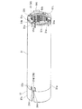
図2は、アクチュエータ100の外観を示す側面図である。図3は、アクチュエータ100の断面図である。図4は、アクチュエータ100のモータ部30および減速ギヤ部50を示す拡大断面図である。
図2、図3に示すように、アクチュエータ100は、第一ハウジング10と、第二ハウジング20と、モータ部30と、モータ部30の回転力を減速して出力する減速ギヤ部50と、減速ギヤ部50を介して伝達されるモータ部30の回転力により回転するスクリュー軸60と、コイルスプリング70と、を備えている。
FIG. 2 is a side view showing the appearance of the actuator 100. FIG. 3 is a sectional view of the actuator 100. FIG. 4 is an enlarged cross-sectional view showing the motor unit 30 and the reduction gear unit 50 of the actuator 100.
As shown in FIGS. 2 and 3, the actuator 100 includes a first housing 10, a second housing 20, a motor unit 30, a reduction gear unit 50 that decelerates and outputs the rotational force of the motor unit 30, and a reduction gear. A screw shaft 60 that rotates by the rotational force of the motor unit 30 transmitted through the gear unit 50 and a coil spring 70 are provided.

第一ハウジング10は、円筒状で、鉄等の金属製材料から形成されている。
図4に示すように、第一ハウジング10の一端10a(図4における左側端)には、テールゲート2側にピン(図示無し)を介して連結されるジョイント部材11が設けられている。ジョイント部材11は、円板状で第一ハウジング10の一端10の内側に嵌め込まれたプレート部11aと、プレート部11aから第一ハウジング10の外方に突出し、ピン(図示無し)が連結されるジョイント部11bと、を備えている。
The first housing 10 has a cylindrical shape and is made of a metal material such as iron.
As shown in FIG. 4, a joint member 11 is provided at one end 10 a (the left end in FIG. 4) of the first housing 10 and is connected to the tailgate 2 side via a pin (not shown). The joint member 11 has a disc shape and is fitted to the inside of the one end 10 of the first housing 10, and protrudes outward from the plate portion 11 a to the first housing 10, and is connected to a pin (not shown). A joint portion 11b.

第一ハウジング10の一端10aには、キャップ12が装着されている。キャップ12は、ジョイント部材11のジョイント部11bが挿通される挿通孔12hを中央部に有した円板状の閉塞部12aと、閉塞部12aの外周部から筒状に連続して延びる筒状部12bと、を一体に備えている。キャップ12は、筒状部12b内に第一ハウジング10の一端10aが圧入されることで第一ハウジング10に固定されている。   A cap 12 is attached to one end 10 a of the first housing 10. The cap 12 includes a disc-shaped closing portion 12a having an insertion hole 12h through which the joint portion 11b of the joint member 11 is inserted, and a cylindrical portion continuously extending in a cylindrical shape from the outer peripheral portion of the closing portion 12a. 12b. The cap 12 is fixed to the first housing 10 by press-fitting one end 10a of the first housing 10 into the cylindrical portion 12b.

図3に示すように、第二ハウジング20は、第一ハウジング10の内径よりも小さな外径を有した円筒状で、樹脂等の第一ハウジング10よりも軟らかい材料から形成されている。このように、第二ハウジング20は、第一ハウジング10に対して軽量化が図られている。
第二ハウジング20は、一端20a側(図3における左端側)が、第一ハウジング10の他端10b側(図3における右端側)から第一ハウジング10内に挿入されている。第二ハウジング20は、第一ハウジング10に対し、他端10bから出没する方向に相対移動可能とされている。
As shown in FIG. 3, the second housing 20 has a cylindrical shape having an outer diameter smaller than the inner diameter of the first housing 10 and is made of a material softer than the first housing 10 such as resin. Thus, the second housing 20 is lighter than the first housing 10.
The second housing 20 has one end 20a side (left end side in FIG. 3) inserted into the first housing 10 from the other end 10b side of the first housing 10 (right end side in FIG. 3). The second housing 20 can be moved relative to the first housing 10 in a direction in which the second housing 20 protrudes and appears from the other end 10b.

第二ハウジング20の他端20bは、深絞り加工等により底部20cが形成されている。この底部20cの径方向中央に、後述のジョイント部材21のジョイント部21bを挿通可能な貫通孔20dが形成されている。
また、第二ハウジング20の他端20bには、底部20cの内側にジョイント部材21が設けられている。ジョイント部材21は、自動車1の開口部3の側枠部3sと第二ハウジング20とを連結するためのものである。ジョイント部材21は、第二ハウジング20の他端20bの内側に嵌め込まれたプレート部21aと、プレート部21aから底部20cに形成された貫通孔20dを介して外方に突出するジョイント部21bと、を有している。このジョイント部21bに、ピン(図示無し)を介して開口部3の側枠部3sが連結される。
The other end 20b of the second housing 20 has a bottom 20c formed by deep drawing or the like. A through hole 20d through which a joint portion 21b of a joint member 21 described later can be inserted is formed in the center in the radial direction of the bottom portion 20c.
Further, a joint member 21 is provided at the other end 20b of the second housing 20 inside the bottom portion 20c. The joint member 21 is for connecting the side frame 3 s of the opening 3 of the automobile 1 and the second housing 20. The joint member 21 includes a plate portion 21a fitted inside the other end 20b of the second housing 20, a joint portion 21b protruding outward from the plate portion 21a through a through hole 20d formed in the bottom portion 20c, have. The side frame 3s of the opening 3 is connected to the joint 21b via a pin (not shown).

プレート部21aは底部20cに面するように配置され、第二ハウジング20の他端20bにかしめ加工等により固定されている。また、プレート部21aの径方向中央には、第二ハウジング20の内方に突出する雄ネジ部21cが設けられている。この雄ネジ部21cに、円筒状のインナーチューブ24の他端24bが螺合されている。   The plate portion 21a is disposed so as to face the bottom portion 20c, and is fixed to the other end 20b of the second housing 20 by caulking or the like. Further, a male screw portion 21c protruding inward of the second housing 20 is provided at the radial center of the plate portion 21a. The other end 24b of the cylindrical inner tube 24 is screwed into the male screw portion 21c.

円筒状のインナーチューブ24は、第二ハウジング20内に配置されている。インナーチューブ24は、例えばアルミに引き抜き加工を施して形成される。このインナーチューブ24の他端24bに、ジョイント部材21の雄ネジ部21cに螺合する雌ネジ部24cが刻設されている。   The cylindrical inner tube 24 is disposed in the second housing 20. The inner tube 24 is formed by, for example, drawing aluminum. On the other end 24b of the inner tube 24, a female screw portion 24c that is screwed into the male screw portion 21c of the joint member 21 is formed.

(モータ部)
図5は、モータ部30のヨーク31および減速ギヤ部50のインターナルギヤ51を示す斜視図である。
図4、図5に示すように、モータ部30は、ヨーク31と、ヨーク31の内周面31fに固定されたマグネット32と、ヨーク31の径方向内側に回転自在に設けられたアーマチュア130と、アーマチュア130に電流を供給する給電部35と、アーマチュア130の回転位置を検出する検出部36と、を備えている。
(Motor part)
FIG. 5 is a perspective view showing the yoke 31 of the motor unit 30 and the internal gear 51 of the reduction gear unit 50.
As shown in FIGS. 4 and 5, the motor unit 30 includes a yoke 31, a magnet 32 fixed to the inner peripheral surface 31 f of the yoke 31, and an armature 130 rotatably provided on the radially inner side of the yoke 31. The power supply unit 35 that supplies current to the armature 130 and the detection unit 36 that detects the rotational position of the armature 130 are provided.

ヨーク31は、金属製で、円筒状をなし、第一ハウジング10内に配置されている。ヨーク31の外径は、第一ハウジング10の内径よりも所定寸法小さい。ヨーク31の一端31a側には、ホルダ部材37が設けられている。ホルダ部材37は、ヨーク31の一端31aを塞ぐ円板状のプレート部37aと、プレート部37aからヨーク31の内側に挿入された第一筒状部37bと、プレート部37aから第一筒状部37bと反対側に向かって延びるよう形成された第二筒状部37cと、を有する。   The yoke 31 is made of metal, has a cylindrical shape, and is disposed in the first housing 10. The outer diameter of the yoke 31 is smaller than the inner diameter of the first housing 10 by a predetermined dimension. A holder member 37 is provided on the one end 31 a side of the yoke 31. The holder member 37 includes a disk-shaped plate portion 37a that closes one end 31a of the yoke 31, a first cylindrical portion 37b that is inserted from the plate portion 37a to the inside of the yoke 31, and a first cylindrical portion that extends from the plate portion 37a. 37b and a second cylindrical portion 37c formed to extend toward the opposite side.

プレート部37aおよび第二筒状部37cは、ヨーク31の外径と略同径の外径を有している。ホルダ部材37は、第一筒状部37bをヨーク31内に挿入し、プレート部37aをヨーク31の一端31a(図4における左側端)に突き当てて装着される。
図5に示すように、第一筒状部37bには、その外周面にヨーク31の軸方向に延びる突起37dが形成されている。ヨーク31の一端31aには、突起37dが係合するスリット31dが形成されている。突起37dとスリット31dとが係合することで、ホルダ部材37は、ヨーク31に対し、周方向に相対移動不能に設けられている。
The plate portion 37 a and the second cylindrical portion 37 c have an outer diameter that is substantially the same as the outer diameter of the yoke 31. The holder member 37 is mounted by inserting the first cylindrical portion 37b into the yoke 31 and abutting the plate portion 37a against one end 31a (the left end in FIG. 4) of the yoke 31.
As shown in FIG. 5, the first cylindrical portion 37 b is formed with a projection 37 d extending in the axial direction of the yoke 31 on the outer peripheral surface thereof. At one end 31a of the yoke 31, there is formed a slit 31d with which the projection 37d is engaged. The holder member 37 is provided so as not to move relative to the yoke 31 in the circumferential direction by engaging the projection 37d with the slit 31d.

図4に示すように、ヨーク31の他端31b側(図4における右端側)には、後述する減速ギヤ部50を構成するインターナルギヤ(ギヤケース、リングギヤ)51が挿入されている。インターナルギヤ51は、円板状のプレート部51aと、プレート部51aの外周部からヨーク31の他端31bに向かって延びる円筒状の筒状部51bと、プレート部51aとは反対側の端部で筒状部51bから外周側に拡径したフランジ部51cと、を一体に備えている。
このインターナルギヤ51は、プレート部51aをヨーク31の一端31a側に向けて筒状部51bがヨーク31内に挿入され、フランジ部51cをヨーク31の他端13bに突き当てて装着される。
As shown in FIG. 4, an internal gear (gear case, ring gear) 51 constituting a reduction gear unit 50 described later is inserted on the other end 31 b side (right end side in FIG. 4) of the yoke 31. The internal gear 51 includes a disc-shaped plate portion 51a, a cylindrical tubular portion 51b extending from the outer peripheral portion of the plate portion 51a toward the other end 31b of the yoke 31, and an end opposite to the plate portion 51a. And a flange portion 51c having a diameter expanded from the cylindrical portion 51b to the outer peripheral side.
The internal gear 51 is mounted with the plate portion 51 a facing the one end 31 a side of the yoke 31, the cylindrical portion 51 b inserted into the yoke 31, and the flange portion 51 c abutting against the other end 13 b of the yoke 31.

図5に示すように、インターナルギヤ51のフランジ部51cにはスリット51dが形成され、ヨーク31の他端31bから軸方向に延びるよう形成された突起31eがかしめ加工等によって係合される。スリット51dと突起31eとが係合されることにより、インターナルギヤ51は、ヨーク31に対し、周方向に相対移動不能に設けられている。   As shown in FIG. 5, a slit 51d is formed in the flange portion 51c of the internal gear 51, and a protrusion 31e formed so as to extend in the axial direction from the other end 31b of the yoke 31 is engaged by caulking or the like. By engaging the slit 51d and the protrusion 31e, the internal gear 51 is provided so as not to move relative to the yoke 31 in the circumferential direction.

図4に示すように、ホルダ部材37の第二筒状部37cと、ジョイント部材11のプレート部11aとの間には、エンドダンパ38が設けられている。エンドダンパ38は、弾性を有したゴム系材料からなり、ホルダ部材37の第二筒状部37cと、ジョイント部材11のプレート部11aとの間に挟み込まれた円板状のプレート部38aと、プレート部38aの外周部からホルダ部材37側に延び、第二筒状部37cが内側に挿入される筒状部38bと、を一体に有している。
ジョイント部材11のプレート部11aとエンドダンパ38のプレート部38a、互いに当接した状態になっている。そして、各プレート部11a,38aの何れか一方には凸部が、他方にはこの凸部が嵌る凹部(何れも図示無し)が形成されている。これにより、各プレート部11a,38a同士が相対回転しないようになっている。
As shown in FIG. 4, an end damper 38 is provided between the second cylindrical portion 37 c of the holder member 37 and the plate portion 11 a of the joint member 11. The end damper 38 is made of a rubber-based material having elasticity, and a disk-shaped plate portion 38a sandwiched between the second cylindrical portion 37c of the holder member 37 and the plate portion 11a of the joint member 11, A cylindrical portion 38b that extends from the outer peripheral portion of the plate portion 38a toward the holder member 37 and into which the second cylindrical portion 37c is inserted is integrally provided.
The plate portion 11a of the joint member 11 and the plate portion 38a of the end damper 38 are in contact with each other. A convex portion is formed on one of the plate portions 11a and 38a, and a concave portion (both not shown) into which the convex portion is fitted is formed on the other. As a result, the plate portions 11a and 38a do not rotate relative to each other.

ここで、ヨーク31の一端31a側では、エンドダンパ38の筒状部38bが、ホルダ部材37の第二筒状部37cと第一ハウジング10との間に介在している。これにより、ヨーク31と第一ハウジング10との間には、クリアランスC1が形成されている。   Here, on the one end 31 a side of the yoke 31, the cylindrical portion 38 b of the end damper 38 is interposed between the second cylindrical portion 37 c of the holder member 37 and the first housing 10. Thereby, a clearance C <b> 1 is formed between the yoke 31 and the first housing 10.

ヨーク31の内周面31fに固定されたマグネット32は、ヨーク31の中心軸方向に長く、ヨーク31の内周面31fの周方向に間隔を空けて複数個が設けられている。
ヨーク31の径方向内側に設けられたアーマチュア130は、シャフト33と、シャフト33に固定されたコア34aと、コア34aに巻回されているコイル34bと、を有する。
The magnet 32 fixed to the inner peripheral surface 31f of the yoke 31 is long in the central axis direction of the yoke 31, and a plurality of magnets 32 are provided at intervals in the circumferential direction of the inner peripheral surface 31f of the yoke 31.
The armature 130 provided on the radially inner side of the yoke 31 includes a shaft 33, a core 34a fixed to the shaft 33, and a coil 34b wound around the core 34a.

シャフト33は、ヨーク31の中心軸方向に沿って延びるよう設けられている。シャフト33は、一端33aが、ホルダ部材37のプレート部37aの中央部に設けられた環状の軸受38Aに、その中心軸回りに回動自在に支持されている。
シャフト33の他端33bは、インターナルギヤ51のプレート部51aの中央部に設けられた環状の軸受38Bに、その中心軸回りに回転自在に支持されている。
The shaft 33 is provided so as to extend along the central axis direction of the yoke 31. One end 33a of the shaft 33 is supported by an annular bearing 38A provided at the center of the plate portion 37a of the holder member 37 so as to be rotatable about its central axis.
The other end 33b of the shaft 33 is supported by an annular bearing 38B provided at the center of the plate portion 51a of the internal gear 51 so as to be rotatable about its central axis.

コア34aは、2つの軸受38A,38Bの間で、シャフト33の外周面に一体に設けられている。コア34aは、放射状に延びる複数のティース131を有している。これらティース131に、それぞれ絶縁性のインシュレータ132を介してコイル34bが巻回されている。   The core 34a is integrally provided on the outer peripheral surface of the shaft 33 between the two bearings 38A and 38B. The core 34a has a plurality of teeth 131 extending radially. Coils 34b are wound around these teeth 131 via insulating insulators 132, respectively.

このように構成されたアーマチュア130に電流を供給する給電部35は、ホルダ部材37に保持されている。給電部35は、ホルダ部材37に保持され、コイル34bに給電するためのブラシ35aと、シャフト33に設けられブラシ35aと摺接する整流子35bと、を有している。ブラシ35aには、外部の電源から給電する配線(図示無し)が接続されている。この配線(図示無し)は、ホルダ部材37のプレート部37a、エンドダンパ38、ジョイント部材11のプレート部11aを貫通し、アクチュエータ100の他端10b(図4における左側端)から外部に導出される。
整流子35bは、コイル34bと電気的に接続されている。
The power feeding unit 35 that supplies current to the armature 130 configured as described above is held by a holder member 37. The power feeding section 35 is held by a holder member 37 and includes a brush 35a for feeding power to the coil 34b, and a commutator 35b provided on the shaft 33 and in sliding contact with the brush 35a. A wiring (not shown) for supplying power from an external power source is connected to the brush 35a. This wiring (not shown) passes through the plate portion 37a of the holder member 37, the end damper 38, and the plate portion 11a of the joint member 11, and is led out from the other end 10b (left end in FIG. 4) of the actuator 100 to the outside. .
The commutator 35b is electrically connected to the coil 34b.

アーマチュア130の回転位置を検出するための検出部36は、センサマグネット39と、センサ基板40と、を備えている。
センサマグネット39は、ホルダ部材37のプレート部37aに対して第二筒状部37c側で、シャフト33の一端33a(図4における左側端)に一体に設けられている。
センサ基板40は、板状で、ホルダ部材37の第二筒状部37c内に保持されている。このセンサ基板40には、センサマグネット39と対向する側に、センサマグネット39がシャフト33とともに回転したときに、その回転を検出するホールIC等の磁気検出子40sが設けられている。センサ基板40には、磁気検出子40sにおける検出信号を外部に出力する出力信号線(図示無し)が接続されている。
The detection unit 36 for detecting the rotational position of the armature 130 includes a sensor magnet 39 and a sensor substrate 40.
The sensor magnet 39 is provided integrally with one end 33 a (the left end in FIG. 4) of the shaft 33 on the second cylindrical portion 37 c side with respect to the plate portion 37 a of the holder member 37.
The sensor substrate 40 has a plate shape and is held in the second cylindrical portion 37 c of the holder member 37. The sensor substrate 40 is provided with a magnetic detector 40 s such as a Hall IC that detects the rotation of the sensor magnet 39 together with the shaft 33 on the side facing the sensor magnet 39. Connected to the sensor substrate 40 is an output signal line (not shown) for outputting a detection signal from the magnetic detector 40s to the outside.

このようなモータ部30は、給電部35の配線(図示無し)およびブラシ35aを通してコイル34bに通電すると、コイル34bで発生する磁力と、ヨーク31に固定されたマグネット32で発生する磁力との間に生じる磁気的な吸引力や反発力によって、シャフト33がその中心軸回りに回転駆動される。   When such a motor unit 30 energizes the coil 34 b through the wiring (not shown) of the power supply unit 35 and the brush 35 a, it is between the magnetic force generated by the coil 34 b and the magnetic force generated by the magnet 32 fixed to the yoke 31. The shaft 33 is rotationally driven around its central axis by the magnetic attractive force and repulsive force generated in the above.

検出部36では、シャフト33と一体に設けられた検出部36のセンサマグネット39の回転を、センサ基板40の磁気検出子40sで検出することで、シャフト33の回転回数を検出する。磁気検出子40sで検出されたセンサマグネット39の回転、すなわちシャフト33の回転は、出力信号線(図示無し)を介し、アクチュエータ100の他端10bから外部に出力される。   The detection unit 36 detects the number of rotations of the shaft 33 by detecting the rotation of the sensor magnet 39 of the detection unit 36 provided integrally with the shaft 33 by the magnetic detector 40 s of the sensor substrate 40. The rotation of the sensor magnet 39 detected by the magnetic detector 40s, that is, the rotation of the shaft 33 is output to the outside from the other end 10b of the actuator 100 via an output signal line (not shown).

(減速ギヤ部)
このように構成されたモータ部30の給電部35とは反対側に、減速ギヤ部50が設けられている。減速ギヤ部50は、インターナルギヤ51と、第一サンギヤ52と、第一段遊星ギヤ53と、第一キャリア54と、第二サンギヤ55と、第二段遊星ギヤ56と、第二キャリア57と、を備えている。
(Reduction gear)
A reduction gear unit 50 is provided on the opposite side of the power supply unit 35 of the motor unit 30 configured as described above. The reduction gear unit 50 includes an internal gear 51, a first sun gear 52, a first stage planetary gear 53, a first carrier 54, a second sun gear 55, a second stage planetary gear 56, and a second carrier 57. And.

ヨーク31の他端31b内に設けられたインターナルギヤ51は、筒状部51bの内周面に、ギヤ歯51gが形成されている。
第一サンギヤ52は、シャフト33の他端33bに嵌め込まれ、その外周面にギヤ歯52gが形成されている。
The internal gear 51 provided in the other end 31b of the yoke 31 has gear teeth 51g formed on the inner peripheral surface of the cylindrical portion 51b.
The first sun gear 52 is fitted into the other end 33b of the shaft 33, and gear teeth 52g are formed on the outer peripheral surface thereof.

第一段遊星ギヤ53は、第一サンギヤ52の外周部に、例えば3個が設けられている。各第一段遊星ギヤ53は、その外周面に第一サンギヤ52のギヤ歯52gおよびインターナルギヤ51のギヤ歯51gに噛み合うギヤ歯53gが形成されている。
第一キャリア54は、円板状で、複数の第一段遊星ギヤ53に対し、シャフト33とは反対側に配置されている。第一キャリア54は、円板状に形成され、かつ第一段遊星ギヤ53を回転自在に支持する支持軸が組み付けられている。
For example, three first stage planetary gears 53 are provided on the outer periphery of the first sun gear 52. Each first stage planetary gear 53 has gear teeth 53g that mesh with the gear teeth 52g of the first sun gear 52 and the gear teeth 51g of the internal gear 51 on the outer peripheral surface thereof.
The first carrier 54 has a disc shape and is disposed on the opposite side of the shaft 33 with respect to the plurality of first stage planetary gears 53. The first carrier 54 is formed in a disc shape, and a support shaft that rotatably supports the first stage planetary gear 53 is assembled.

第二サンギヤ55は、第一キャリア54の中心部に、シャフト33とは反対側に一体に設けられている。第二サンギヤ55は、その外周面にギヤ歯55gが形成されている。   The second sun gear 55 is integrally provided on the opposite side of the shaft 33 at the center of the first carrier 54. The second sun gear 55 has gear teeth 55g formed on the outer peripheral surface thereof.

第二段遊星ギヤ56は、第二サンギヤ55の外周部に、例えば3個が設けられている。各第二段遊星ギヤ56は、その外周面に第二サンギヤ55のギヤ歯55gおよびインターナルギヤ51のギヤ歯51gに噛み合うギヤ歯56gが形成されている。
第二キャリア57は、複数の第二段遊星ギヤ56に対し、シャフト33とは反対側に配置されている。第二キャリア57は、円板状に形成され、かつ第二段遊星ギヤ56を回転自在に支持する支持軸(図示無し)が組み付けられている。
For example, three second stage planetary gears 56 are provided on the outer periphery of the second sun gear 55. Each second stage planetary gear 56 is formed with gear teeth 56g meshing with the gear teeth 55g of the second sun gear 55 and the gear teeth 51g of the internal gear 51 on the outer peripheral surface thereof.
The second carrier 57 is disposed on the side opposite to the shaft 33 with respect to the plurality of second stage planetary gears 56. The second carrier 57 is formed in a disk shape, and a support shaft (not shown) that rotatably supports the second stage planetary gear 56 is assembled.

ここで、インターナルギヤ51のプレート部51aと第一段遊星ギヤ53との間、および第一キャリア54と第二段遊星ギヤ56との間には、ワッシャ58A、58Bが配されている。
これら第一サンギヤ52、第二サンギヤ55は、それぞれ焼結材などの金属製とされ、第一キャリア54、第二キャリア57もまた金属製とされている。また、インターナルギヤ51、第一段遊星ギヤ53、第二段遊星ギヤ56は、それぞれ樹脂製とされている。
Here, washers 58A and 58B are arranged between the plate portion 51a of the internal gear 51 and the first stage planetary gear 53 and between the first carrier 54 and the second stage planetary gear 56.
The first sun gear 52 and the second sun gear 55 are each made of metal such as a sintered material, and the first carrier 54 and the second carrier 57 are also made of metal. The internal gear 51, the first stage planetary gear 53, and the second stage planetary gear 56 are each made of resin.

さらに、インターナルギヤ51のギヤ歯51g、第一サンギヤ52のギヤ歯52g、第一段遊星ギヤ53のギヤ歯53g、第二サンギヤ55のギヤ歯55g、第二段遊星ギヤ56のギヤ歯56gは、それぞれハス歯歯車とされている。これにより、減速ギヤ部50の各ギヤ間における噛み合い代を増やし、作動音を低減することができる。
また、インターナルギヤ51のギヤ歯51gは、第一段遊星ギヤ53のギヤ歯53gに噛み合う部分と、第二段遊星ギヤ56のギヤ歯56gに噛み合う部分とが、連続する同一ピッチのギヤ歯51gにより形成されている。これにより、インターナルギヤ51を容易に製作することができる。
Furthermore, the gear teeth 51g of the internal gear 51, the gear teeth 52g of the first sun gear 52, the gear teeth 53g of the first stage planetary gear 53, the gear teeth 55g of the second sun gear 55, and the gear teeth 56g of the second stage planetary gear 56. Are respectively helical gears. Thereby, the meshing allowance between each gear of the reduction gear part 50 can be increased, and an operating noise can be reduced.
Further, the gear teeth 51g of the internal gear 51 are gear teeth having the same pitch in which the portion that meshes with the gear teeth 53g of the first stage planetary gear 53 and the portion that meshes with the gear teeth 56g of the second stage planetary gear 56 are continuous. 51g. Thereby, the internal gear 51 can be manufactured easily.

このような減速ギヤ部50においては、シャフト33が回転すると、第一サンギヤ52がシャフト33と一体に回転する。第一サンギヤ52の回転は、その外周側の第一段遊星ギヤ53に伝達される。各第一段遊星ギヤ53は、第一サンギヤ52のギヤ歯52gと、外周側のインターナルギヤ51のギヤ歯51gとに噛み合いながら、第一サンギヤ52の外周部を公転するとともに、第一キャリア54に組み付けられた支持軸を中心に自転する、いわゆる遊星運動する。
これら複数の第一段遊星ギヤ53の遊星運動により、第一キャリア54がシャフト33と同軸回りに減速されて回転する。
In such a reduction gear unit 50, when the shaft 33 rotates, the first sun gear 52 rotates integrally with the shaft 33. The rotation of the first sun gear 52 is transmitted to the first stage planetary gear 53 on the outer peripheral side thereof. Each first-stage planetary gear 53 revolves around the outer periphery of the first sun gear 52 while meshing with the gear teeth 52g of the first sun gear 52 and the gear teeth 51g of the internal gear 51 on the outer peripheral side, and the first carrier A so-called planetary motion that rotates around a support shaft assembled to 54.
Due to the planetary motion of the plurality of first stage planetary gears 53, the first carrier 54 is decelerated about the shaft 33 and rotated.

第一キャリア54が回転すると、第二サンギヤ55が一体に回転し、その外周側の第二段遊星ギヤ56に伝達される。各第二段遊星ギヤ56は、第二サンギヤ55のギヤ歯55gと、外周側のインターナルギヤ51のギヤ歯51gとに噛み合いながら、第二サンギヤ55の外周部で公転すると共に、第二キャリア57に組み付けられた支持軸を中心に自転する、いわゆる遊星運動する。
これら複数の第二段遊星ギヤ56の遊星運動により、第二キャリア57がシャフト33と同軸回りに減速されて回転する。
When the first carrier 54 rotates, the second sun gear 55 rotates integrally and is transmitted to the second stage planetary gear 56 on the outer peripheral side. Each second stage planetary gear 56 revolves around the outer periphery of the second sun gear 55 while meshing with the gear teeth 55g of the second sun gear 55 and the gear teeth 51g of the internal gear 51 on the outer peripheral side. A so-called planetary motion that rotates around a support shaft assembled to 57.
Due to the planetary motion of the plurality of second stage planetary gears 56, the second carrier 57 is decelerated about the shaft 33 and rotated.

スクリュー軸60は、その一端60aが、第一ハウジング10内に設けられた軸受61により、その中心軸回りに回動自在に保持されている。軸受61は、かしめ加工等によって第一ハウジング10内に嵌め込み固定された円環状の軸受ホルダ62の内側に保持されている。   One end 60 a of the screw shaft 60 is held by a bearing 61 provided in the first housing 10 so as to be rotatable around its central axis. The bearing 61 is held inside an annular bearing holder 62 that is fitted and fixed in the first housing 10 by caulking or the like.

図6は、インターナルギヤ51と軸受ホルダ62との間に配するダンパ部材63を示す斜視展開図である。
図4、図6に示すように、軸受61および軸受ホルダ62と、インターナルギヤ51のフランジ部51cとの間には、ダンパ部材63が設けられている。
FIG. 6 is an exploded perspective view showing a damper member 63 disposed between the internal gear 51 and the bearing holder 62.
As shown in FIGS. 4 and 6, a damper member 63 is provided between the bearing 61 and the bearing holder 62 and the flange portion 51 c of the internal gear 51.

ダンパ部材63は、弾性を有したゴム系材料からなり、軸受61および軸受ホルダ62と、インターナルギヤ51のフランジ部51cとの間に挟み込まれた円板状のプレート部63aと、プレート部63aの外周部からインターナルギヤ51側に延び、インターナルギヤ51のフランジ部51cが内側に挿入される筒状部63bと、を一体に有している。   The damper member 63 is made of a rubber-based material having elasticity, and includes a disc-shaped plate portion 63a sandwiched between the bearing 61 and the bearing holder 62 and the flange portion 51c of the internal gear 51, and a plate portion 63a. A cylindrical portion 63b that extends from the outer peripheral portion to the internal gear 51 side and into which the flange portion 51c of the internal gear 51 is inserted is integrally provided.

ここで、ヨーク31の他端31b側では、ダンパ部材63の筒状部63bが、ヨーク31の他端31bおよびインターナルギヤ51のフランジ部51cと第一ハウジング10との間に介在し、ヨーク31と第一ハウジング10との間に、クリアランスC1が形成される。すなわち、モータ部30および減速ギヤ部50は、これらの軸方向両端に設けられたエンドダンパ38およびダンパ部材63によって、第一ハウジング10にフローティング支持されている。   Here, on the other end 31 b side of the yoke 31, the cylindrical portion 63 b of the damper member 63 is interposed between the other end 31 b of the yoke 31 and the flange portion 51 c of the internal gear 51 and the first housing 10. A clearance C <b> 1 is formed between 31 and the first housing 10. That is, the motor unit 30 and the reduction gear unit 50 are floatingly supported by the first housing 10 by the end dampers 38 and the damper members 63 provided at both ends in the axial direction.

また、第一ハウジング10にかしめ固定された軸受ホルダ62において、ダンパ部材63に対向する側には、周方向に間隔をあけて複数の突起62tが形成されている。また、インターナルギヤ51のフランジ部51cにおいて、ダンパ部材63に対向する側には、周方向に間隔を空けて複数の突起51tが形成されている。ダンパ部材63には、周方向に間隔を空けて、突起51t,62tのそれぞれが挿入される複数の挿入孔63h,63gが形成されている。すなわち、インターナルギヤ51に形成された突起51tと、第一ハウジング10に固定された軸受ホルダ62に形成された突起62tとによって、第一ハウジング10に対してヨーク31が相対回転することを防ぐ。また、突起51tと突起62tとがダンパ部材63の挿入孔63h、63gに挿入されることにより、モータ部30および減速ギヤ部50の振動が、第一ハウジング10に伝達されることを防ぐ。   Further, in the bearing holder 62 that is caulked and fixed to the first housing 10, a plurality of protrusions 62 t are formed on the side facing the damper member 63 at intervals in the circumferential direction. Further, in the flange portion 51c of the internal gear 51, a plurality of protrusions 51t are formed on the side facing the damper member 63 at intervals in the circumferential direction. The damper member 63 is formed with a plurality of insertion holes 63h and 63g into which the protrusions 51t and 62t are inserted, respectively, at intervals in the circumferential direction. Specifically, the protrusion 31 t formed on the internal gear 51 and the protrusion 62 t formed on the bearing holder 62 fixed to the first housing 10 prevent the yoke 31 from rotating relative to the first housing 10. . Further, the protrusions 51 t and the protrusions 62 t are inserted into the insertion holes 63 h and 63 g of the damper member 63, thereby preventing vibrations of the motor unit 30 and the reduction gear unit 50 from being transmitted to the first housing 10.

スクリュー軸60の一端60aには、減速ギヤ部50の第二キャリア57の中央部に形成された出力ギヤ孔57hに噛み合うギヤ64が設けられている。これにより、スクリュー軸60は、モータ部30におけるシャフト33の回転が、減速ギヤ部50を介して伝達され、その中心軸回りに回転駆動される。   At one end 60 a of the screw shaft 60, a gear 64 that meshes with an output gear hole 57 h formed at the center of the second carrier 57 of the reduction gear unit 50 is provided. As a result, the rotation of the shaft 33 in the motor unit 30 is transmitted to the screw shaft 60 via the reduction gear unit 50 and is driven to rotate around the central axis.

図7は、第一ハウジング10と第二ハウジング20との継ぎ目の部分を示す拡大断面図である。
同図に示すように、スクリュー軸60の外周面には、螺旋状に連続したネジ条60nが形成されている。スクリュー軸60の他端60b側は、第二ハウジング20のインナーチューブ24の一端24a内に設けられたナット部材25内に挿入されている。
FIG. 7 is an enlarged cross-sectional view illustrating a joint portion between the first housing 10 and the second housing 20.
As shown in the figure, on the outer peripheral surface of the screw shaft 60, a continuous screw thread 60n is formed. The other end 60 b side of the screw shaft 60 is inserted into a nut member 25 provided in one end 24 a of the inner tube 24 of the second housing 20.

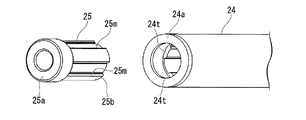
図8は、インナーチューブ24とナット部材25とを示す斜視展開図である。
同図に示すように、ナット部材25は、その外周面に、周方向に間隔を空けて複数(例えば、この実施形態では4つ)の溝25mが形成されている。一方、ナット部材25が挿入されたインナーチューブ24の内周面には、インナーチューブ24の軸方向に沿って連続する突条24tが、周方向に間隔を空けて複数(例えば、この実施形態では4つ)形成されている。
FIG. 8 is an exploded perspective view showing the inner tube 24 and the nut member 25.
As shown in the figure, the nut member 25 has a plurality of (for example, four in this embodiment) grooves 25m formed on the outer peripheral surface thereof at intervals in the circumferential direction. On the other hand, on the inner peripheral surface of the inner tube 24 into which the nut member 25 is inserted, a plurality of protrusions 24t continuous along the axial direction of the inner tube 24 are spaced apart in the circumferential direction (for example, in this embodiment). 4) formed.

ナット部材25は、インナーチューブ24の突条24tに溝25mを噛み合わせて配置される。これにより、インナーチューブ24に対するナット部材25の周方向の回転が規制される。そして、インナーチューブ24は、他端24bが第二ハウジング20の他端20bに設けられたジョイント部材21に螺合されているので、このジョイント部材21とインナーチューブ24とを介してナット部材25と第二ハウジング20との相対回転が規制される。   The nut member 25 is disposed by engaging the groove 25 m with the protrusion 24 t of the inner tube 24. Thereby, the circumferential rotation of the nut member 25 with respect to the inner tube 24 is restricted. And since the other end 24b of the inner tube 24 is screwed into the joint member 21 provided on the other end 20b of the second housing 20, the nut member 25 is connected to the inner tube 24 via the joint member 21 and the inner tube 24. Relative rotation with the second housing 20 is restricted.

図7に示すように、ナット部材25の溝25mは、ナット部材25において第一ハウジング10側とは反対側の端部25bから、第一ハウジング10側に向かって所定長の長さで形成されている。これにより、溝25mは、ナット部材25の第一ハウジング10側の端部25aから一定長の範囲では形成されていない。また、インナーチューブ24に形成された突条24tも、インナーチューブ24の一端24aから所定長の範囲には形成されていない。   As shown in FIG. 7, the groove 25m of the nut member 25 is formed with a predetermined length from the end 25b of the nut member 25 opposite to the first housing 10 side toward the first housing 10 side. ing. Accordingly, the groove 25m is not formed within a certain length from the end 25a of the nut member 25 on the first housing 10 side. Further, the protrusion 24 t formed on the inner tube 24 is not formed within a predetermined length from the one end 24 a of the inner tube 24.

このように、溝25mを、軸方向全体に渡って形成せず、ナット部材25の溝25mとインナーチューブ24の突条24tとの噛み合いによって、ナット部材25が第一ハウジング10から離間する方向に移動するのを規制している。
また、ナット部材25の端部25aは、インナーチューブ24内に、スナップリング25rやかしめ加工等によって固定されている。
Thus, the groove 25m is not formed over the entire axial direction, and the nut member 25 is separated from the first housing 10 by the engagement between the groove 25m of the nut member 25 and the protrusion 24t of the inner tube 24. The movement is restricted.
The end 25a of the nut member 25 is fixed in the inner tube 24 by a snap ring 25r, caulking, or the like.

スクリュー軸60は、ネジ条60nが、ナット部材25の内周面に形成された雌ネジ溝25nに螺合するとともに、先端部60sがナット部材25を貫通して突出している。
スクリュー軸60の先端部60sには、外周側に張り出すストッパ65が、かしめ加工等によって一体に固定されている。このストッパ65によって、ナット部材25のスクリュー軸60からの抜けが防止される。
The screw shaft 60 has a thread 60 n screwed into a female screw groove 25 n formed on the inner peripheral surface of the nut member 25, and a tip portion 60 s protruding through the nut member 25.
A stopper 65 protruding to the outer peripheral side is integrally fixed to the distal end portion 60s of the screw shaft 60 by caulking or the like. The stopper 65 prevents the nut member 25 from coming off from the screw shaft 60.

図3に示すように、第一ハウジング10および第二ハウジング20内に、コイルスプリング70が配置されている。コイルスプリング70は、例えば金属製である。コイルスプリング70は、第二ハウジング20内で、インナーチューブ24がその内側に挿入されている。また、第一ハウジング10内で、コイルスプリング70の内側には、第一ハウジング10内に設けられた筒状のガイドチューブ18が挿入されている。   As shown in FIG. 3, a coil spring 70 is disposed in the first housing 10 and the second housing 20. The coil spring 70 is made of metal, for example. The coil spring 70 has the inner tube 24 inserted inside the second housing 20. A cylindrical guide tube 18 provided in the first housing 10 is inserted inside the coil spring 70 in the first housing 10.

図7に示すように、ガイドチューブ18は、内径がインナーチューブ24の外径よりも大きく、その内側にインナーチューブ24が挿入配置されている。また、ガイドチューブ18の他端18b側の外周面18fは、一端18a側から他端18b側に向かってその外径が漸次小さくなるテーパ状に形成されている。   As shown in FIG. 7, the guide tube 18 has an inner diameter larger than the outer diameter of the inner tube 24, and the inner tube 24 is inserted and disposed inside the guide tube 18. Further, the outer peripheral surface 18f on the other end 18b side of the guide tube 18 is formed in a tapered shape whose outer diameter gradually decreases from the one end 18a side toward the other end 18b side.

また、図4に示すように、ガイドチューブ18の一端18a側には、外周側に張り出すフランジ部18cが一体に形成されている。さらに、ガイドチューブ18のフランジ部18cと、軸受ホルダ62との間には、円環状のシール部材66が挟み込まれている。シール部材66は、ゴム系材料等の防水性および弾性を有した材料からなり、その外周面は、第一ハウジング10に密着している。
コイルスプリング70は、その内側に、インナーチューブ24およびガイドチューブ18が挿通されることで、コイルスプリング70の伸縮時に、コイルスプリング70が伸縮方向側方に撓んだり座屈したりするのを抑える。
Further, as shown in FIG. 4, a flange portion 18 c that projects to the outer peripheral side is integrally formed on the one end 18 a side of the guide tube 18. Further, an annular seal member 66 is sandwiched between the flange portion 18 c of the guide tube 18 and the bearing holder 62. The seal member 66 is made of a waterproof and elastic material such as a rubber-based material, and the outer peripheral surface thereof is in close contact with the first housing 10.
The coil spring 70 is inserted into the inner tube 24 and the guide tube 18 so that the coil spring 70 is prevented from being bent or buckled laterally in the expansion / contraction direction when the coil spring 70 is expanded / contracted.

このようなコイルスプリング70は、第二ハウジング20のジョイント部材21のプレート部21aと、ガイドチューブ18のフランジ部18cとの間に、圧縮状態で設けられている。これにより、コイルスプリング70は、第一ハウジング10と第二ハウジング20とが互いに離間して、アクチュエータ100の全長を延ばす方向に付勢している。
また、コイルスプリング70によって、ガイドチューブ18のフランジ部18cがシール部材66側に押圧される。換言すれば、ガイドチューブ18のフランジ部18cと軸受ホルダ62とにより、シール部材66が挟持されている。
Such a coil spring 70 is provided in a compressed state between the plate portion 21 a of the joint member 21 of the second housing 20 and the flange portion 18 c of the guide tube 18. Accordingly, the coil spring 70 is biased in a direction in which the first housing 10 and the second housing 20 are separated from each other and the entire length of the actuator 100 is extended.
Further, the flange portion 18 c of the guide tube 18 is pressed toward the seal member 66 by the coil spring 70. In other words, the seal member 66 is sandwiched between the flange portion 18 c of the guide tube 18 and the bearing holder 62.

図7に示すように、第一ハウジング10の他端10bには、その外周側に円筒状のアウターリング80が設けられている。アウターリング80は、金属等の剛性の高い材料により形成されており、第一ハウジング10の他端10bに圧入されて固定されている。
また、アウターリング80の先端部80aは、第一ハウジング10の他端10bよりも第二ハウジング20側に僅かに突出している。アウターリング80の先端部80aの内周面には、円環状で防水性と弾性とを有するゴム系材料からなる円環状のシールリング81が一体に設けられている。
このように、材料の異なるアウターリング80とシールリング81は、例えば2色成形により形成される。
As shown in FIG. 7, the other end 10b of the first housing 10 is provided with a cylindrical outer ring 80 on the outer peripheral side thereof. The outer ring 80 is made of a highly rigid material such as metal, and is press-fitted and fixed to the other end 10 b of the first housing 10.
Further, the distal end portion 80 a of the outer ring 80 slightly protrudes toward the second housing 20 than the other end 10 b of the first housing 10. An annular seal ring 81 made of a rubber-based material having an annular shape and waterproofness and elasticity is integrally provided on the inner peripheral surface of the distal end portion 80 a of the outer ring 80.
Thus, the outer ring 80 and the seal ring 81 made of different materials are formed by, for example, two-color molding.

シールリング81の内周面は、第二ハウジング20の外周面に摺接している。このシールリング81により、第一ハウジング10と第二ハウジング20との隙間からアクチュエータ100内に水等が侵入するのを防止する。   The inner peripheral surface of the seal ring 81 is in sliding contact with the outer peripheral surface of the second housing 20. The seal ring 81 prevents water or the like from entering the actuator 100 from the gap between the first housing 10 and the second housing 20.

(車両ドア開閉用アクチュエータの動作)
次に、アクチュエータ100の動作について説明する。
モータ部30のシャフト33を回転駆動させると、シャフト33の回転が減速ギヤ部50を介してスクリュー軸60に伝達される。これによってスクリュー軸60が回転すると、ナット部材25がスクリュー軸60の軸方向に沿って移動する。ナット部材25は、第二ハウジング20と一体化されたインナーチューブ24に固定されているので、これによって、第一ハウジング10に対して第二ハウジング20が出没し、アクチュエータ100が伸縮する。
(Operation of the actuator for opening and closing the vehicle door)
Next, the operation of the actuator 100 will be described.
When the shaft 33 of the motor unit 30 is driven to rotate, the rotation of the shaft 33 is transmitted to the screw shaft 60 via the reduction gear unit 50. Accordingly, when the screw shaft 60 rotates, the nut member 25 moves along the axial direction of the screw shaft 60. Since the nut member 25 is fixed to the inner tube 24 integrated with the second housing 20, the second housing 20 protrudes and retracts with respect to the first housing 10, and the actuator 100 expands and contracts.

このとき、第一ハウジング10は鉄等の金属製材料から形成されている一方、第二ハウジング20は樹脂等の軟らかい材料で形成されているので、第一ハウジング10と第二ハウジング20の双方にスライド痕が付くことなく、第二ハウジング20のみにスライド痕が付く。しかも第二ハウジング20を樹脂等により形成することで、スライド痕が目立たず、意匠性が維持される。   At this time, the first housing 10 is made of a metal material such as iron, while the second housing 20 is made of a soft material such as resin, so that both the first housing 10 and the second housing 20 Only the second housing 20 has a slide mark without a slide mark. In addition, by forming the second housing 20 from resin or the like, slide marks are not noticeable, and the design is maintained.

図9は、アクチュエータ100を縮めた状態を示す断面図である。
同図に示すように、第一ハウジング10に対して第二ハウジング20が没入すると、自動車1の開口部3に設けられたバックゲート2が閉じられる。一方、図3に示すように、第一ハウジング10に対して第二ハウジング20が突出すると、自動車1の開口部3に設けられたバックゲート2が開けられる。このとき、アクチュエータ100を伸ばした状態でモータ部30の動作を停止させても、コイルスプリング70の付勢力によって、第一ハウジング10に対し第二ハウジング20が突出した状態が維持される。
FIG. 9 is a sectional view showing the actuator 100 in a contracted state.
As shown in the figure, when the second housing 20 is immersed in the first housing 10, the back gate 2 provided in the opening 3 of the automobile 1 is closed. On the other hand, as shown in FIG. 3, when the second housing 20 protrudes from the first housing 10, the back gate 2 provided in the opening 3 of the automobile 1 is opened. At this time, even if the operation of the motor unit 30 is stopped with the actuator 100 extended, the state in which the second housing 20 protrudes from the first housing 10 is maintained by the biasing force of the coil spring 70.

ここで、上述の実施形態では、第一ハウジング10内にガイドチューブ18を設け、このガイドチューブ18のフランジ部18cと軸受ホルダ62とにより、シール部材66を挟持している。このため、シール部材66にフランジ部18cと軸受ホルダ62とが密着し、これらフランジ部18cと軸受ホルダ62との間のシール性が確保される。この結果、例えば、第一ハウジング10と第二ハウジング20との隙間から水や塵埃が侵入した場合であっても、シール部材66によって、モータ部30の内部に水や塵埃が侵入してしまうことを防止できる。よって、アクチュエータ100の耐久性を向上できるとともに、作動の信頼性を高めることができる。   Here, in the above-described embodiment, the guide tube 18 is provided in the first housing 10, and the seal member 66 is sandwiched between the flange portion 18 c of the guide tube 18 and the bearing holder 62. For this reason, the flange portion 18 c and the bearing holder 62 are in close contact with the seal member 66, and the sealing performance between the flange portion 18 c and the bearing holder 62 is ensured. As a result, for example, even when water or dust enters from the gap between the first housing 10 and the second housing 20, the seal member 66 causes water or dust to enter the motor unit 30. Can be prevented. Therefore, the durability of the actuator 100 can be improved and the operation reliability can be increased.

しかも、第一ハウジング10とガイドチューブ18との間にコイルスプリング70を設け、コイルスプリング70のバネ力を利用してシール部材66側にフランジ部18cを押圧させている。このため、シール部材66に対するフランジ部18cおよび軸受ホルダ62の密着性を高めることができる。
また、ガイドチューブ18によって、圧縮時におけるコイルスプリング70の圧縮方向に交差する方向の座屈を防止できる。コイルスプリング70の押圧力は、フランジ部18cを介してシール部材66に伝達されるため、コイルスプリング70の押圧力がシール部材66に均等に作用する。このため、シール部材66に対するフランジ部18cおよび軸受ホルダ62の密着性をさらに高めることができる。
In addition, a coil spring 70 is provided between the first housing 10 and the guide tube 18, and the flange portion 18 c is pressed toward the seal member 66 using the spring force of the coil spring 70. For this reason, the adhesiveness of the flange part 18c and the bearing holder 62 with respect to the sealing member 66 can be improved.
Further, the guide tube 18 can prevent buckling in the direction intersecting the compression direction of the coil spring 70 during compression. Since the pressing force of the coil spring 70 is transmitted to the seal member 66 via the flange portion 18 c, the pressing force of the coil spring 70 acts on the seal member 66 evenly. For this reason, the adhesiveness of the flange part 18c and the bearing holder 62 with respect to the sealing member 66 can further be improved.

ここで、軸受ホルダ62にシール部材66を密着させるように設け、モータ部30側の防水性、防塵性を高めるためにガイドチューブ18を利用しているが、このガイドチューブ18を設けることによって、第一ハウジング10の軸受ホルダ62に対応する位置に段差面を設けて軸受ホルダ62とシール部材66とを密着させる必要がない。つまり、第一ハウジング10のガイドチューブ18に対応する箇所を、このガイドチューブ18の形状に合わせて深絞り加工を施し、第一ハウジング10に、シール部材66と当接する段差面(内壁)を形成する必要がない。このため、第一ハウジング10を筒状に形成でき、この第一ハウジング10の加工コストを低減できる。   Here, the seal member 66 is provided in close contact with the bearing holder 62, and the guide tube 18 is used to improve the waterproofness and dustproofness on the motor unit 30 side. However, by providing the guide tube 18, There is no need to provide a stepped surface at a position corresponding to the bearing holder 62 of the first housing 10 to bring the bearing holder 62 and the seal member 66 into close contact with each other. That is, the portion corresponding to the guide tube 18 of the first housing 10 is deep-drawn according to the shape of the guide tube 18 to form a step surface (inner wall) that contacts the seal member 66 in the first housing 10. There is no need to do. For this reason, the 1st housing 10 can be formed in a cylinder shape and the processing cost of this 1st housing 10 can be reduced.

また、第一ハウジング10を筒状に形成できることから、アクチュエータ100を組み付ける際、第1ハウジング10にモータ部30、減速ギヤ部50、軸受ホルダ62を組み付けた後、第一ハウジング10の他端10b側からシール部材66、ガイドチューブ18、およびコイルスプリング70を、この順に挿入していけばよい。このため、アクチュエータ100の組立性も向上できる。   Further, since the first housing 10 can be formed in a cylindrical shape, when the actuator 100 is assembled, after the motor unit 30, the reduction gear unit 50, and the bearing holder 62 are assembled to the first housing 10, the other end 10b of the first housing 10 is assembled. The sealing member 66, the guide tube 18, and the coil spring 70 may be inserted in this order from the side. For this reason, the assembly property of the actuator 100 can also be improved.

また、第二ハウジング20内にインナーチューブ24を設けることにより、ガイドチューブ18の他端18b側にインナーチューブ24が配置された状態になっている。このため、ガイドチューブ18とインナーチューブ24の2つのチューブ18,24により、コイルスプリング70の全長をガイドすることができる。
また、インナーチューブ24によって、圧縮時におけるコイルスプリング70の圧縮方向に交差する方向の座屈を防止できる。このため、コイルスプリング70の押圧力がシール部材66にさらに均等に作用する。この結果、シール部材66に対するフランジ部18cおよび軸受ホルダ62の密着性をさらに高めることができる。
さらに、インナーチューブ24がナット部材25を保持することで、ナット部材25を保持するために他の部品等を備える必要がなく、部品点数を減少できる。
Further, by providing the inner tube 24 in the second housing 20, the inner tube 24 is disposed on the other end 18 b side of the guide tube 18. For this reason, the entire length of the coil spring 70 can be guided by the two tubes 18 and 24 of the guide tube 18 and the inner tube 24.
Further, the inner tube 24 can prevent buckling in the direction intersecting the compression direction of the coil spring 70 during compression. For this reason, the pressing force of the coil spring 70 acts on the seal member 66 more evenly. As a result, the adhesion between the flange portion 18c and the bearing holder 62 with respect to the seal member 66 can be further enhanced.
Furthermore, since the inner tube 24 holds the nut member 25, it is not necessary to provide other parts or the like to hold the nut member 25, and the number of parts can be reduced.

さらに、アクチュエータ100は、第一ハウジング10の端部に設けられた筒状のアウターリング80と、アウターリング80の内周面に設けられ、第二ハウジング20の外周面に摺接する環状のシールリング81と、をさらに備えている。これにより、第一ハウジング10と第二ハウジング20との隙間から、侵入物(雨水や塵埃等)が侵入するのを防ぐことができる。   Furthermore, the actuator 100 includes a cylindrical outer ring 80 provided at the end of the first housing 10 and an annular seal ring that is provided on the inner peripheral surface of the outer ring 80 and that is in sliding contact with the outer peripheral surface of the second housing 20. 81. Thereby, it is possible to prevent an intruding object (rain water, dust, or the like) from entering from the gap between the first housing 10 and the second housing 20.

また、モータ部30のヨーク31の内周面31gに、減速ギヤ部50のインターナルギヤ51が設けられている。このため、ヨーク31とインターナルギヤ51との相対位置を、容易かつ高精度に決定できる。
しかも、インターナルギヤ51に、モータ部30のシャフト33を回転自在に支持する軸受38Bを設けている。このため、モータ部30の中心軸と減速ギヤ部50の中心軸とを、容易かつ高精度に位置合わせすることができる。また、部品に過度なストレスが掛かって耐久性が損なわれたり、部品同士の当たりが強くなって作動音が高まったりする等の不具合が生じるのを防ぐことができる。したがって、アクチュエータ100の耐久性、作動性等を高めるとともに、振動や作動音を低減して高品質化を図ることが可能となる。
また、インターナルギヤ51に、モータ部30のシャフト33を回転自在に支持する軸受38Bを設けることにより、ヨーク31に軸受38Bを支持するための絞り加工等を施す必要がなくなるので、ヨーク31の加工コストを低減できる。
In addition, an internal gear 51 of the reduction gear unit 50 is provided on the inner peripheral surface 31 g of the yoke 31 of the motor unit 30. For this reason, the relative position of the yoke 31 and the internal gear 51 can be determined easily and with high accuracy.
Moreover, the internal gear 51 is provided with a bearing 38 </ b> B that rotatably supports the shaft 33 of the motor unit 30. For this reason, the central axis of the motor part 30 and the central axis of the reduction gear part 50 can be aligned easily and with high accuracy. In addition, it is possible to prevent the occurrence of problems such as excessive stress applied to the components and loss of durability, or the strong contact between the components and increased operating noise. Therefore, it is possible to improve the durability and operability of the actuator 100 and to improve the quality by reducing vibration and operating noise.
In addition, by providing the internal gear 51 with the bearing 38B that rotatably supports the shaft 33 of the motor unit 30, it is not necessary to perform drawing processing or the like for supporting the bearing 38B on the yoke 31. Processing cost can be reduced.

さらに、減速ギヤ部50を遊星減速機構により構成することで、減速ギヤ部50の減速比を高めつつ、省スペース化できる。
そして、減速ギヤ部50を構成する遊星減速機構が複数段の構成であり、インターナルギヤ51の内周面に形成するギヤ歯51gを、第一段遊星ギヤ53、第二段遊星ギヤ56のそれぞれに噛み合う同一ピッチで形成するようにした。これにより、インターナルギヤ51を容易に製作することができる。
Furthermore, by configuring the reduction gear unit 50 with a planetary reduction mechanism, it is possible to save space while increasing the reduction ratio of the reduction gear unit 50.
The planetary reduction mechanism constituting the reduction gear unit 50 has a multi-stage configuration, and the gear teeth 51 g formed on the inner peripheral surface of the internal gear 51 are connected to the first stage planetary gear 53 and the second stage planetary gear 56. They were formed at the same pitch that meshed with each other. Thereby, the internal gear 51 can be manufactured easily.

また、インターナルギヤ51は、ヨーク31の内周面31gにかしめ加工により固定されている。このため、ヨーク31に対してインターナルギヤ51を確実に位置決め固定できる。さらに、モータ部30の回転時に、その反力によって、インターナルギヤ51が回転しまうのを防ぐことができる。   The internal gear 51 is fixed to the inner peripheral surface 31g of the yoke 31 by caulking. For this reason, the internal gear 51 can be reliably positioned and fixed with respect to the yoke 31. Furthermore, it is possible to prevent the internal gear 51 from rotating due to the reaction force when the motor unit 30 rotates.

また、ヨーク31の一端31a側に設けられたホルダ部材37に、エンドダンパ38が設けられていると共に、ヨーク31の他端31b側に設けられたインターナルギヤ51に、ダンパ部材38が設けられている。これにより、ヨーク31と第一ハウジング10との間にクリアランスC1が形成される。すなわち、第一ハウジング10に、モータ部30、給電部35および減速ギヤ部50が、エンドダンパ38およびダンパ部材38を介してフローティング支持されている。このため、モータ部30や減速ギヤ部50の振動、およびこれらモータ部30や減速ギヤ部50と、スクリュー軸60との間における振動が、第一ハウジング10に伝わるのを抑制できる。このため、アクチュエータ100の作動時の振動や騒音を低減できる。   An end damper 38 is provided on the holder member 37 provided on the one end 31 a side of the yoke 31, and a damper member 38 is provided on the internal gear 51 provided on the other end 31 b side of the yoke 31. ing. Thereby, a clearance C <b> 1 is formed between the yoke 31 and the first housing 10. That is, the motor unit 30, the power feeding unit 35, and the reduction gear unit 50 are floatingly supported on the first housing 10 via the end damper 38 and the damper member 38. For this reason, vibrations of the motor unit 30 and the reduction gear unit 50 and vibrations between the motor unit 30 and the reduction gear unit 50 and the screw shaft 60 can be prevented from being transmitted to the first housing 10. For this reason, vibration and noise during operation of the actuator 100 can be reduced.

さらに、インターナルギヤ51に、ダンパ部材63側に突出する突起51tが形成され、軸受ホルダ62に、ダンパ部材63側に突出する突起62tが形成され、ダンパ部材63に、突起51tや突起62tが挿入可能な挿入孔63h,63gが形成されている。このため、ダンパ部材63において、インターナルギヤ51側と軸受ホルダ62側とにおける周方向の相対変位を吸収することができる。これにより、モータ部30の作動時における回転方向の振動や衝撃の発生を抑えることができる。また、外力によってスクリュー軸60が回転したときの振動や衝撃がモータ部30や減速ギヤ部50側に入力されるのを防止することができる。   Further, the internal gear 51 is formed with a protrusion 51t that protrudes toward the damper member 63, the bearing holder 62 is formed with a protrusion 62t that protrudes toward the damper member 63, and the protrusion 51t and the protrusion 62t are formed on the damper member 63. Insertable insertion holes 63h and 63g are formed. For this reason, the damper member 63 can absorb the circumferential relative displacement between the internal gear 51 side and the bearing holder 62 side. Thereby, generation | occurrence | production of the vibration and impact of a rotation direction at the time of the action | operation of the motor part 30 can be suppressed. Further, it is possible to prevent vibrations and shocks when the screw shaft 60 is rotated by an external force from being input to the motor unit 30 and the reduction gear unit 50 side.

(その他の実施形態)
なお、本発明は上述の実施形態に限られるものではなく、本発明の趣旨を逸脱しない範囲において、上述の実施形態に種々の変更を加えたものを含む。
例えば、アクチュエータ100の各部の構成は、本発明の主旨の範囲内で適宜変更することができる。一例として、上述の実施形態では、減速ギヤ部50を遊星減速機構により構成した場合について説明した。しかしながら、これに限られるものではなく、遊星減速機構に代えてさまざまな減速機構を適用することが可能である。この場合、モータ部30のヨーク31の内周面に減速機構のギヤケースを配置し、さらに、ギヤケースに、シャフト33を回転自在に支持するための軸受38Bを設ければよい。
(Other embodiments)
The present invention is not limited to the above-described embodiment, and includes various modifications made to the above-described embodiment without departing from the spirit of the present invention.
For example, the configuration of each part of the actuator 100 can be appropriately changed within the scope of the gist of the present invention. As an example, in the above-described embodiment, the case where the reduction gear unit 50 is configured by a planetary reduction mechanism has been described. However, the present invention is not limited to this, and various reduction mechanisms can be applied instead of the planetary reduction mechanism. In this case, a gear case of the speed reduction mechanism may be disposed on the inner peripheral surface of the yoke 31 of the motor unit 30, and a bearing 38B for rotatably supporting the shaft 33 may be provided on the gear case.

また、上述の実施形態では、ナット部材25の外周面に、4つの溝25mを形成するとともに、インナーチューブ24の内周面に、4つの突条24tを形成することにより、インナーチューブ24に対するナット部材25の周方向の回転が規制される場合について説明した。しかしながら、これに限られるものではなく、ナット部材25の外周面に少なくとも1つ溝25mが形成されていればよく、また、これに対応してインナーチューブ24の内周面に少なくとも1つ突条24tが形成されていればよい。さらに、ナット部材25の外周面に突条を形成する一方、インナーチューブ24の内周面に、突条と係合可能な溝を形成してもよい。   Further, in the above-described embodiment, the four grooves 25m are formed on the outer peripheral surface of the nut member 25, and the four protrusions 24t are formed on the inner peripheral surface of the inner tube 24, whereby the nut for the inner tube 24 is formed. The case where rotation in the circumferential direction of the member 25 is restricted has been described. However, the present invention is not limited to this, and it is sufficient that at least one groove 25m is formed on the outer peripheral surface of the nut member 25, and correspondingly, at least one protrusion is formed on the inner peripheral surface of the inner tube 24. 24t may be formed. Furthermore, while a protrusion is formed on the outer peripheral surface of the nut member 25, a groove engageable with the protrusion may be formed on the inner peripheral surface of the inner tube 24.

また、上述の実施形態では、筒状の第一ハウジング10内に、筒状のガイドチューブ18を挿入し、ガイドチューブ18のフランジ部18cと軸受ホルダ62とにより、シール部材66を挟持した場合について説明した。しかしながら、これに限られるものではなく、第一ハウジング10のガイドチューブ18に対応する箇所を、このガイドチューブ18の形状に対応するように深絞り加工等により形成し、これによって形成された段差面と軸受ホルダ62とによりシール部材66を挟持するように構成してもよい。この場合、第一ハウジング10の深絞り加工等を施した箇所の外周面に、コイルスプリング70を配置する。   In the above embodiment, the cylindrical guide tube 18 is inserted into the cylindrical first housing 10, and the seal member 66 is sandwiched between the flange portion 18 c of the guide tube 18 and the bearing holder 62. explained. However, the present invention is not limited to this, and a portion corresponding to the guide tube 18 of the first housing 10 is formed by deep drawing or the like so as to correspond to the shape of the guide tube 18, and the step surface formed thereby The seal member 66 may be sandwiched between the bearing holder 62 and the bearing holder 62. In this case, the coil spring 70 is disposed on the outer peripheral surface of the first housing 10 where the deep drawing or the like is performed.

さらに、上述の実施形態では、モータ部30のシャフト33の回転力を、減速ギヤ部50を介してスクリュー軸60に伝達させている場合について説明した。しかしながら、これに限られるものではなく、シャフト33にスクリュー軸60を直接連結してもよい。この場合、軸受ホルダ62に設けられた軸受61によって、スクリュー軸60を回転自在に支持してもよいし、シャフト33を回転自在に支持してもよい。   Furthermore, in the above-described embodiment, the case where the rotational force of the shaft 33 of the motor unit 30 is transmitted to the screw shaft 60 via the reduction gear unit 50 has been described. However, the present invention is not limited to this, and the screw shaft 60 may be directly connected to the shaft 33. In this case, the screw shaft 60 may be rotatably supported by the bearing 61 provided in the bearing holder 62, or the shaft 33 may be rotatably supported.

また、上述の実施形態では、ヨーク31の一端31a側に設けられたホルダ部材37に、エンドダンパ38を設けると共に、ヨーク31の他端31b側に設けられたインターナルギヤ51に、ダンパ部材38を設けた場合について説明した。そして、第一ハウジング10に、モータ部30、給電部35および減速ギヤ部50を、エンドダンパ38およびダンパ部材38を介してフローティング支持させた場合について説明した。しかしながら、これに限られるものではなく、少なくともモータ部30の両端側で、かつ第一ハウジング10とヨーク31との間に、エンドダンパ38やダンパ部材38が介在するように構成されていればよい。このように構成することで、少なくともモータ部30の作動時における振動が、第一ハウジン部10に伝達されてしまうのを抑制できる。   In the above-described embodiment, the end damper 38 is provided on the holder member 37 provided on the one end 31 a side of the yoke 31, and the damper member 38 is provided on the internal gear 51 provided on the other end 31 b side of the yoke 31. The case where is provided has been described. The case where the motor unit 30, the power feeding unit 35, and the reduction gear unit 50 are floatingly supported on the first housing 10 via the end damper 38 and the damper member 38 has been described. However, the present invention is not limited to this, and it is sufficient that the end damper 38 and the damper member 38 are interposed at least at both ends of the motor unit 30 and between the first housing 10 and the yoke 31. . By configuring in this way, it is possible to suppress at least vibration during operation of the motor unit 30 from being transmitted to the first housing part 10.

さらに、アクチュエータ100の用途は、バックゲート2の開閉用に限らず、他の様々なドアの開閉に用いることができる。
これ以外にも、本発明の主旨を逸脱しない限り、上記実施の形態で挙げた構成を取捨選択したり、他の構成に適宜変更したりすることが可能である。
Furthermore, the use of the actuator 100 is not limited to the opening and closing of the back gate 2 but can be used to open and close various other doors.
In addition to this, the configuration described in the above embodiment can be selected or changed to another configuration as appropriate without departing from the gist of the present invention.

1…自動車
2…テールゲート(ドア)
3…開口部
A…アクチュエータ
10…第一ハウジング
18…ガイドチューブ(ガイド部材)
18c…フランジ部
20…第二ハウジング
24…インナーチューブ(第二ガイド部材)
25…ナット部材(従動部材)
30…モータ部(モータ)
31…ヨーク
31e…突起
31f…内周面
33…シャフト(回転軸)
38…エンドダンパ
38A,38B…軸受
50…減速ギヤ部
51…インターナルギヤ
51d…スリット
51g…ギヤ歯
51t…突起
52…第一サンギヤ
53…第一段遊星ギヤ
54…第一キャリア
55…第二サンギヤ
56…第二段遊星ギヤ
57…第二キャリア
60…スクリュー軸(駆動軸)
61…軸受
62…軸受ホルダ
62t…突起
63…ダンパ部材
63g,63h…挿入孔
66…シール部材
70…コイルスプリング
80…アウターリング(ホルダ部材)
81…シールリング
130…アーマチュア
1 ... car 2 ... tailgate (door)
3 ... opening A ... actuator 10 ... first housing 18 ... guide tube (guide member)
18c ... Flange 20 ... Second housing 24 ... Inner tube (second guide member)
25 ... Nut member (driven member)
30 ... Motor part (motor)
31 ... Yoke 31e ... Protrusion 31f ... Inner peripheral surface 33 ... Shaft (rotating shaft)
38 ... End dampers 38A, 38B ... Bearing 50 ... Reduction gear 51 ... Internal gear 51d ... Slit 51g ... Gear teeth 51t ... Projection 52 ... First sun gear 53 ... First stage planetary gear 54 ... First carrier 55 ... Second Sun gear 56 ... second stage planetary gear 57 ... second carrier 60 ... screw shaft (drive shaft)
61 ... bearing 62 ... bearing holder 62t ... projection 63 ... damper members 63g, 63h ... insertion hole 66 ... seal member 70 ... coil spring 80 ... outer ring (holder member)
81 ... Seal ring 130 ... Armature

Claims (4)

筒状の第一ハウジングと、
該第一ハウジングに対して出没可能に設けられた筒状の第二ハウジングと、
前記第一ハウジングに内蔵されたモータと、
前記モータの回転軸の回転力を受けて回転駆動される駆動軸と、
前記第一ハウジング内に設けられ、前記回転軸および前記駆動軸の何れか一方のみを回転自在に支持する軸受を保持する軸受ホルダと、
前記第二ハウジングに固定され、前記駆動軸の回転にともなって前記駆動軸の軸方向に沿って移動することで、前記第一ハウジングに対して前記第二ハウジングを出没させる従動部材と、
前記第一ハウジングおよび前記第二ハウジング内に設けられ、前記第一ハウジングに対して前記第二ハウジングを突出させる方向の付勢力を付与するコイルスプリングと、
前記第一ハウジングおよび前記第二ハウジング内に設けられ、前記コイルスプリングの内側に配置される筒状のガイド部材と、
前記第一ハウジングの内周面に円環状の内壁を設けるとともに、該内壁と前記軸受ホルダとにより、前記モータへの侵入物の侵入を防止するためのシール部材を挟持し、
前記ガイド部材の前記軸受ホルダ側の端部に、前記コイルスプリングと前記シール部材との間に介在するフランジ部を形成し、
該フランジ部を前記内壁として機能させると共に、前記コイルスプリングにより、前記フランジ部を前記軸受ホルダに向かって押圧することを特徴とするアクチュエータ。
A cylindrical first housing;
A cylindrical second housing provided so as to be movable in and out of the first housing;
A motor built in the first housing;
A drive shaft that is rotationally driven in response to the rotational force of the rotation shaft of the motor;
A bearing holder that is provided in the first housing and holds a bearing that rotatably supports only one of the rotating shaft and the driving shaft;
A driven member that is fixed to the second housing and moves along the axial direction of the drive shaft along with the rotation of the drive shaft, thereby causing the second housing to protrude and retract with respect to the first housing;
A coil spring that is provided in the first housing and the second housing and applies a biasing force in a direction in which the second housing protrudes from the first housing;
A cylindrical guide member provided in the first housing and the second housing and disposed inside the coil spring;
An annular inner wall is provided on the inner peripheral surface of the first housing, and the inner wall and the bearing holder sandwich a seal member for preventing intrusion of the intruder into the motor,
Forming a flange portion interposed between the coil spring and the seal member at an end of the guide member on the bearing holder side;
An actuator characterized in that the flange portion functions as the inner wall, and the flange portion is pressed toward the bearing holder by the coil spring.
前記第二ハウジングの内部において、前記コイルスプリングの内側に位置して前記ガイド部材の前記軸受ホルダとは反対側の端部内に挿入されるとともに、前記従動部材を保持する第二ガイド部材をさらに備えることを特徴とする請求項1に記載のアクチュエータ。   A second guide member that is positioned inside the coil spring and is inserted into an end portion of the guide member opposite to the bearing holder inside the second housing and that holds the driven member. The actuator according to claim 1. 前記第一ハウジングの前記第二ハウジング側の端部に設けられた筒状のホルダ部材と、
前記ホルダ部材の内周面に設けられ、前記第二ハウジングの外周面に摺接する環状のシールリングと、
をさらに備えることを特徴とする請求項1または請求項2に記載のアクチュエータ。
A cylindrical holder member provided at an end of the first housing on the second housing side;
An annular seal ring provided on the inner peripheral surface of the holder member and in sliding contact with the outer peripheral surface of the second housing;
The actuator according to claim 1, further comprising:
請求項1〜請求項3の何れか一項に記載のアクチュエータを、開口部に対して開閉可能に設けられたドアを開閉駆動するために用いた車両ドア開閉用アクチュエータであって、
前記開口部および前記ドアの何れか一方に前記第一ハウジングを連結し、
前記開口部および前記ドアの何れか他方に前記第二ハウジングを連結したことを特徴とする車両ドア開閉用アクチュエータ。
An actuator for opening and closing a vehicle door, wherein the actuator according to any one of claims 1 to 3 is used to open and close a door that can be opened and closed with respect to an opening.
Connecting the first housing to one of the opening and the door;
A vehicle door opening and closing actuator, wherein the second housing is connected to either the opening or the door.
JP2015152706A 2015-07-31 2015-07-31 Actuator and vehicle door opening / closing actuator Expired - Fee Related JP6579850B2 (en)

Priority Applications (1)

Application Number Priority Date Filing Date Title
JP2015152706A JP6579850B2 (en) 2015-07-31 2015-07-31 Actuator and vehicle door opening / closing actuator

Applications Claiming Priority (1)

Application Number Priority Date Filing Date Title
JP2015152706A JP6579850B2 (en) 2015-07-31 2015-07-31 Actuator and vehicle door opening / closing actuator

Publications (2)

Publication Number Publication Date
JP2017032071A JP2017032071A (en) 2017-02-09
JP6579850B2 true JP6579850B2 (en) 2019-09-25

Family

ID=57988201

Family Applications (1)

Application Number Title Priority Date Filing Date
JP2015152706A Expired - Fee Related JP6579850B2 (en) 2015-07-31 2015-07-31 Actuator and vehicle door opening / closing actuator

Country Status (1)

Country Link
JP (1) JP6579850B2 (en)

Families Citing this family (8)

* Cited by examiner, † Cited by third party
Publication number Priority date Publication date Assignee Title
JP6692277B2 (en) 2016-11-14 2020-05-13 株式会社ミツバ Actuators and actuators for opening and closing vehicle doors
CN107317428A (en) * 2017-03-28 2017-11-03 德昌电机(深圳)有限公司 Automobile tail gate lowering or hoisting gear and its drive device
JP6873847B2 (en) * 2017-07-05 2021-05-19 株式会社ミツバ Opening and closing body drive device
CN107795227A (en) * 2017-11-30 2018-03-13 无锡典聚科技有限公司 A kind of electronic strut with reliable sealing structure
JP7004274B2 (en) * 2019-04-17 2022-01-21 三井金属アクト株式会社 Drive device for open / close body
JP7024154B2 (en) * 2019-04-17 2022-02-24 三井金属アクト株式会社 Drive device for open / close body
JP7266509B2 (en) * 2019-10-23 2023-04-28 株式会社ハイレックスコーポレーション drive
CN111697739B (en) * 2020-06-03 2022-05-27 浙江东政电机有限公司 Multi-sealing underwater traction motor

Family Cites Families (1)

* Cited by examiner, † Cited by third party
Publication number Priority date Publication date Assignee Title
EP2543808B1 (en) * 2011-07-05 2020-03-04 U-Shin Deutschland Zugangssysteme GmbH Actuator device for automatically activating the vehicle door of a motor vehicle

Also Published As

Publication number Publication date
JP2017032071A (en) 2017-02-09

Similar Documents

Publication Publication Date Title
JP6462523B2 (en) Actuator and vehicle door opening / closing actuator
JP6478863B2 (en) Actuator and vehicle door opening / closing actuator
JP6579850B2 (en) Actuator and vehicle door opening / closing actuator
JP6692277B2 (en) Actuators and actuators for opening and closing vehicle doors
JP6676483B2 (en) Actuator and vehicle door opening / closing actuator
JP6937563B2 (en) Vehicle door switchgear
JP7064000B2 (en) Fixed structure, actuator, actuator for opening and closing vehicle doors, and fixing method
JP2020002742A (en) Actuator and vehicle door opening/closing actuator
CN110753804B (en) Motor with speed reducing mechanism
WO2018066500A1 (en) Actuator, and actuator for vehicle
JP2006304553A (en) Motor with speed reducing mechanism
JP6624996B2 (en) Actuator
JP2021081027A (en) Motor with speed reduction mechanism
JP7404218B2 (en) Actuators and vehicle door opening/closing actuators
JP2019094733A (en) Actuator and vehicle door opening-closing actuator
JP2019115159A (en) Electric actuator
JP7041243B2 (en) Actuators and actuators for opening and closing vehicle doors
JP2010078044A (en) Clutch and motor with speed-reduction mechanism
JP2017096325A (en) Planetary gear mechanism and actuator including the same
JP2020169492A (en) Linear driving device
JP2008022651A (en) Motor
JP2018059550A (en) Power transmission mechanism, actuator and actuator for vehicle

Legal Events

Date Code Title Description
A621 Written request for application examination

Free format text: JAPANESE INTERMEDIATE CODE: A621

Effective date: 20180124

A977 Report on retrieval

Free format text: JAPANESE INTERMEDIATE CODE: A971007

Effective date: 20181025

RD03 Notification of appointment of power of attorney

Free format text: JAPANESE INTERMEDIATE CODE: A7423

Effective date: 20181026

A131 Notification of reasons for refusal

Free format text: JAPANESE INTERMEDIATE CODE: A131

Effective date: 20181106

A521 Request for written amendment filed

Free format text: JAPANESE INTERMEDIATE CODE: A523

Effective date: 20181214

A131 Notification of reasons for refusal

Free format text: JAPANESE INTERMEDIATE CODE: A131

Effective date: 20190507

A521 Request for written amendment filed

Free format text: JAPANESE INTERMEDIATE CODE: A523

Effective date: 20190702

TRDD Decision of grant or rejection written
A01 Written decision to grant a patent or to grant a registration (utility model)

Free format text: JAPANESE INTERMEDIATE CODE: A01

Effective date: 20190806

A61 First payment of annual fees (during grant procedure)

Free format text: JAPANESE INTERMEDIATE CODE: A61

Effective date: 20190827

R150 Certificate of patent or registration of utility model

Ref document number: 6579850

Country of ref document: JP

Free format text: JAPANESE INTERMEDIATE CODE: R150

LAPS Cancellation because of no payment of annual fees