JP6579649B2 - Electric motor driven compressor with a heat shield that forms the wall of the diffuser - Google Patents
Electric motor driven compressor with a heat shield that forms the wall of the diffuser Download PDFInfo
- Publication number
- JP6579649B2 JP6579649B2 JP2015060766A JP2015060766A JP6579649B2 JP 6579649 B2 JP6579649 B2 JP 6579649B2 JP 2015060766 A JP2015060766 A JP 2015060766A JP 2015060766 A JP2015060766 A JP 2015060766A JP 6579649 B2 JP6579649 B2 JP 6579649B2
- Authority
- JP
- Japan
- Prior art keywords
- compressor
- housing
- air
- cooling air
- heat shield
- Prior art date
- Legal status (The legal status is an assumption and is not a legal conclusion. Google has not performed a legal analysis and makes no representation as to the accuracy of the status listed.)
- Active
Links
Images


Classifications
-
- F—MECHANICAL ENGINEERING; LIGHTING; HEATING; WEAPONS; BLASTING
- F04—POSITIVE - DISPLACEMENT MACHINES FOR LIQUIDS; PUMPS FOR LIQUIDS OR ELASTIC FLUIDS
- F04D—NON-POSITIVE-DISPLACEMENT PUMPS
- F04D29/00—Details, component parts, or accessories
- F04D29/58—Cooling; Heating; Diminishing heat transfer
- F04D29/582—Cooling; Heating; Diminishing heat transfer specially adapted for elastic fluid pumps
- F04D29/5846—Cooling; Heating; Diminishing heat transfer specially adapted for elastic fluid pumps cooling by injection
-
- F—MECHANICAL ENGINEERING; LIGHTING; HEATING; WEAPONS; BLASTING
- F04—POSITIVE - DISPLACEMENT MACHINES FOR LIQUIDS; PUMPS FOR LIQUIDS OR ELASTIC FLUIDS
- F04C—ROTARY-PISTON, OR OSCILLATING-PISTON, POSITIVE-DISPLACEMENT MACHINES FOR LIQUIDS; ROTARY-PISTON, OR OSCILLATING-PISTON, POSITIVE-DISPLACEMENT PUMPS
- F04C29/00—Component parts, details or accessories of pumps or pumping installations, not provided for in groups F04C18/00 - F04C28/00
- F04C29/04—Heating; Cooling; Heat insulation
- F04C29/047—Cooling of electronic devices installed inside the pump housing, e.g. inverters
-
- F—MECHANICAL ENGINEERING; LIGHTING; HEATING; WEAPONS; BLASTING
- F04—POSITIVE - DISPLACEMENT MACHINES FOR LIQUIDS; PUMPS FOR LIQUIDS OR ELASTIC FLUIDS
- F04D—NON-POSITIVE-DISPLACEMENT PUMPS
- F04D17/00—Radial-flow pumps, e.g. centrifugal pumps; Helico-centrifugal pumps
- F04D17/08—Centrifugal pumps
- F04D17/10—Centrifugal pumps for compressing or evacuating
- F04D17/12—Multi-stage pumps
- F04D17/122—Multi-stage pumps the individual rotor discs being, one for each stage, on a common shaft and axially spaced, e.g. conventional centrifugal multi- stage compressors
- F04D17/125—Multi-stage pumps the individual rotor discs being, one for each stage, on a common shaft and axially spaced, e.g. conventional centrifugal multi- stage compressors the casing being vertically split
-
- F—MECHANICAL ENGINEERING; LIGHTING; HEATING; WEAPONS; BLASTING
- F04—POSITIVE - DISPLACEMENT MACHINES FOR LIQUIDS; PUMPS FOR LIQUIDS OR ELASTIC FLUIDS
- F04D—NON-POSITIVE-DISPLACEMENT PUMPS
- F04D25/00—Pumping installations or systems
- F04D25/02—Units comprising pumps and their driving means
- F04D25/06—Units comprising pumps and their driving means the pump being electrically driven
- F04D25/0606—Units comprising pumps and their driving means the pump being electrically driven the electric motor being specially adapted for integration in the pump
-
- F—MECHANICAL ENGINEERING; LIGHTING; HEATING; WEAPONS; BLASTING
- F04—POSITIVE - DISPLACEMENT MACHINES FOR LIQUIDS; PUMPS FOR LIQUIDS OR ELASTIC FLUIDS
- F04D—NON-POSITIVE-DISPLACEMENT PUMPS
- F04D29/00—Details, component parts, or accessories
- F04D29/05—Shafts or bearings, or assemblies thereof, specially adapted for elastic fluid pumps
- F04D29/051—Axial thrust balancing
- F04D29/0513—Axial thrust balancing hydrostatic; hydrodynamic thrust bearings
-
- F—MECHANICAL ENGINEERING; LIGHTING; HEATING; WEAPONS; BLASTING
- F04—POSITIVE - DISPLACEMENT MACHINES FOR LIQUIDS; PUMPS FOR LIQUIDS OR ELASTIC FLUIDS
- F04D—NON-POSITIVE-DISPLACEMENT PUMPS
- F04D29/00—Details, component parts, or accessories
- F04D29/05—Shafts or bearings, or assemblies thereof, specially adapted for elastic fluid pumps
- F04D29/056—Bearings
- F04D29/057—Bearings hydrostatic; hydrodynamic
-
- F—MECHANICAL ENGINEERING; LIGHTING; HEATING; WEAPONS; BLASTING
- F04—POSITIVE - DISPLACEMENT MACHINES FOR LIQUIDS; PUMPS FOR LIQUIDS OR ELASTIC FLUIDS
- F04D—NON-POSITIVE-DISPLACEMENT PUMPS
- F04D29/00—Details, component parts, or accessories
- F04D29/08—Sealings
- F04D29/10—Shaft sealings
- F04D29/102—Shaft sealings especially adapted for elastic fluid pumps
-
- F—MECHANICAL ENGINEERING; LIGHTING; HEATING; WEAPONS; BLASTING
- F04—POSITIVE - DISPLACEMENT MACHINES FOR LIQUIDS; PUMPS FOR LIQUIDS OR ELASTIC FLUIDS
- F04D—NON-POSITIVE-DISPLACEMENT PUMPS
- F04D29/00—Details, component parts, or accessories
- F04D29/58—Cooling; Heating; Diminishing heat transfer
- F04D29/5806—Cooling the drive system
-
- F—MECHANICAL ENGINEERING; LIGHTING; HEATING; WEAPONS; BLASTING
- F04—POSITIVE - DISPLACEMENT MACHINES FOR LIQUIDS; PUMPS FOR LIQUIDS OR ELASTIC FLUIDS
- F04D—NON-POSITIVE-DISPLACEMENT PUMPS
- F04D29/00—Details, component parts, or accessories
- F04D29/58—Cooling; Heating; Diminishing heat transfer
- F04D29/582—Cooling; Heating; Diminishing heat transfer specially adapted for elastic fluid pumps
- F04D29/584—Cooling; Heating; Diminishing heat transfer specially adapted for elastic fluid pumps cooling or heating the machine
-
- F—MECHANICAL ENGINEERING; LIGHTING; HEATING; WEAPONS; BLASTING
- F04—POSITIVE - DISPLACEMENT MACHINES FOR LIQUIDS; PUMPS FOR LIQUIDS OR ELASTIC FLUIDS
- F04D—NON-POSITIVE-DISPLACEMENT PUMPS
- F04D29/00—Details, component parts, or accessories
- F04D29/58—Cooling; Heating; Diminishing heat transfer
- F04D29/582—Cooling; Heating; Diminishing heat transfer specially adapted for elastic fluid pumps
- F04D29/5853—Cooling; Heating; Diminishing heat transfer specially adapted for elastic fluid pumps heat insulation or conduction
Description
関連出願の相互参照
[0001]本願は、2014年2月19日に出願した、本願の権利者が所有する同時係属出願第14/184,122号に関し、その全開示は参照により本明細書に組み込まれる。
Cross-reference of related applications
[0001] This application is related to copending application No. 14 / 184,122, filed February 19, 2014, owned by the right holder of this application, the entire disclosure of which is incorporated herein by reference.
[0002]本開示は、燃料電池に使用されるような電気モーター駆動圧縮機に関する。 [0002] The present disclosure relates to electric motor driven compressors such as those used in fuel cells.
[0003]燃料電池のカソード側に圧縮空気を供給することで燃料電池の効率を高めるために、空気圧縮機が使用されうる。単一の圧縮機段で得られる圧力よりも高い圧力を必要とするいくつかの用途では、二段圧縮機が使用されうる。二段圧縮機では、軸上に低圧圧縮機翼車が設けられ、同じ軸上に高圧圧縮機翼車が設けられる。この軸は電気モーターによって駆動され、それにより圧縮機翼車が回転されて、空気が低圧圧縮機翼車に入って第1の圧力まで圧縮される。次いで圧縮空気は、圧力をさらに高めるための高圧翼車に送られる。次いで、高圧圧縮機翼車からの空気は、燃料電池反応を促進するために燃料電池に送達される。 [0003] An air compressor can be used to increase the efficiency of a fuel cell by supplying compressed air to the cathode side of the fuel cell. In some applications that require pressures higher than those obtained with a single compressor stage, a two-stage compressor may be used. In the two-stage compressor, a low-pressure compressor wheel is provided on the shaft, and a high-pressure compressor wheel is provided on the same shaft. This shaft is driven by an electric motor which causes the compressor wheel to rotate and air enters the low pressure compressor wheel and is compressed to a first pressure. The compressed air is then sent to a high pressure impeller to further increase the pressure. Air from the high pressure compressor wheel is then delivered to the fuel cell to facilitate the fuel cell reaction.
[0004]燃料電池用の圧縮機で使用される電気モーターは、通常、かなりの熱量を発生させる高速で高出力のモーターである。一般に、モーターと圧縮機内で圧縮されている空気との間の熱伝達、およびモーターと圧縮機軸用の軸受との間の熱伝達を最小限に抑えることが望ましい。 [0004] Electric motors used in compressors for fuel cells are typically high speed, high power motors that generate significant amounts of heat. In general, it is desirable to minimize heat transfer between the motor and the air being compressed in the compressor and between the motor and the bearing for the compressor shaft.
[0005]本開示は、燃料電池または他の用途などに有用な電気モーター駆動圧縮機の実施形態について説明する。例えば一実施形態では、電気モーター駆動圧縮機が、モーターハウジングと、モーターハウジングに取り付けられた圧縮機ハウジングとを備える、ハウジング組立体を含む。モーターハウジングは、モーター固定子およびモーター回転子を内蔵し、かつ、回転可能な軸が貫通する穴を画定する。圧縮機ハウジングは、軸に取り付けられて軸中心線の周りで回転する遠心圧縮機翼車を内蔵する。圧縮機ハウジングはまた、圧縮機翼車に空気を導く空気吸入口と、圧縮機翼車を通過した圧縮空気を集める渦形室とを画定する。圧縮機翼車の出口と渦形室との間のディフューザが、圧縮空気をより低い速度に拡散させてその結果として静圧をより高くする機能を果たす。 [0005] This disclosure describes embodiments of electric motor driven compressors useful for fuel cells or other applications. For example, in one embodiment, an electric motor driven compressor includes a housing assembly that includes a motor housing and a compressor housing attached to the motor housing. The motor housing contains a motor stator and a motor rotor and defines a hole through which the rotatable shaft passes. The compressor housing contains a centrifugal compressor wheel that is attached to the shaft and rotates about the shaft centerline. The compressor housing also defines an air inlet that directs air to the compressor wheel and a vortex chamber that collects compressed air that has passed through the compressor wheel. A diffuser between the compressor wheel exit and the vortex chamber serves to diffuse the compressed air to a lower velocity, resulting in a higher static pressure.
[0006]一実施形態における電気モーター駆動圧縮機は、軸を回転可能に支持する空気軸受を含む。空気軸受に冷却空気を供給するために、ハウジング組立体内に冷却空気通路が画定される。 [0006] An electric motor driven compressor in one embodiment includes an air bearing that rotatably supports a shaft. A cooling air passage is defined in the housing assembly for supplying cooling air to the air bearing.
[0007]本開示によれば、電気モーター駆動圧縮機は、圧縮機ハウジングおよびモーターハウジングとは別に形成されてそれらの間に配置された、遮熱材を含む。遮熱材は、渦形室内に送達される圧縮空気のためのディフューザの1つの壁を画定する。遮熱材はまた、ハウジング組立体と協働して、空気軸受に供給される冷却空気のための冷却空気通路の一部を画定する。 [0007] According to the present disclosure, an electric motor driven compressor includes a heat shield formed separately from and disposed between the compressor housing and the motor housing. The heat shield defines one wall of the diffuser for the compressed air delivered into the vortex chamber. The heat shield also cooperates with the housing assembly to define a portion of the cooling air passage for the cooling air supplied to the air bearing.
[0008]一実施形態では、モーターハウジングは、冷却液を循環させるための冷却液通路を画定し、遮熱材は、モーターハウジングと第1の圧縮機ハウジングとの間に捕捉される取付フランジを画定する。取付フランジは、取付フランジからモーターハウジングの一部分への熱伝達を促進するために、冷却液よって冷却されるモーターハウジングの前述の部分と接触する。 [0008] In one embodiment, the motor housing defines a coolant passage for circulating coolant, and the heat shield includes a mounting flange that is captured between the motor housing and the first compressor housing. Define. The mounting flange contacts the aforementioned portion of the motor housing that is cooled by the coolant to facilitate heat transfer from the mounting flange to a portion of the motor housing.
[0009]一実施形態では、遮熱材およびモーターハウジングは、冷却空気を受け入れるための環状空間をそれらの間に画定するように配置され、また、冷却空気通路は、環状空間から冷却空気を受け入れるように配置される。さらに、遮熱材とモーターハウジングとの間に冷却空気ギャップを画定することができ、この冷却空気ギャップは、環状空間から冷却空気を受け入れるように配置される。 [0009] In one embodiment, the heat shield and the motor housing are arranged to define an annular space therebetween for receiving cooling air, and the cooling air passage receives the cooling air from the annular space Are arranged as follows. Further, a cooling air gap can be defined between the heat shield and the motor housing, and the cooling air gap is arranged to receive cooling air from the annular space.
[0010]圧縮機はまた、第1の圧縮機翼車と空気軸受との中間で軸に固定された第1のシール担体と、第1のシール担体の周りに形成された円周溝内に係合された第1のシールリングとを含むことができる。第1のシールリングは、第1の圧縮機流れ経路と空気軸受との間の空気漏れを防ぐために、遮熱材の径方向内側表面に接触して密閉するように位置決めされる。 [0010] The compressor also includes a first seal carrier secured to the shaft midway between the first compressor wheel and the air bearing, and a circumferential groove formed around the first seal carrier. And an engaged first seal ring. The first seal ring is positioned to contact and seal against the radially inner surface of the heat shield to prevent air leakage between the first compressor flow path and the air bearing.
[0011]本発明の特徴は、本明細書で示されかつ説明される実施形態のような二段直列圧縮機に適用されうる。そのような二段圧縮機の場合、第2の圧縮機ハウジングが、モーターハウジングの反対側の端部に取り付けられ、また、第2の遠心圧縮機翼車が、第2の圧縮機ハウジングに内蔵されて軸の反対側の端部に固定される。第2の圧縮機ハウジングは、第2の圧縮機翼車に空気を導く第2の空気吸入口と、第2の圧縮機翼車を通過しそれによって圧縮された圧縮空気を集める第2の渦形室とを含む、第2の圧縮機流れ経路を画定する。段間導管が、第2の圧縮機翼車によって圧縮された空気がその段間導管により第2の渦形室から第1の空気吸入口内に導かれて、第1の圧縮機翼車によってさらに圧縮されて第1の渦形室に送達されるように、第2の渦形室を第1の空気吸入口に接続する。したがって、第2の圧縮機翼車は、低圧圧縮機翼車を構成し、第1の圧縮機翼車は、高圧圧縮機翼車を構成する。 [0011] The features of the present invention may be applied to a two-stage serial compressor, such as the embodiments shown and described herein. In such a two-stage compressor, the second compressor housing is attached to the opposite end of the motor housing, and the second centrifugal compressor wheel is built into the second compressor housing. And fixed to the opposite end of the shaft. The second compressor housing has a second air inlet for directing air to the second compressor impeller, and a second vortex that collects compressed air that has passed through the second compressor impeller and is thereby compressed. A second compressor flow path including a profile chamber. The interstage conduit has the air compressed by the second compressor wheel guided from the second vortex chamber into the first air inlet by the interstage conduit, and further by the first compressor wheel. The second vortex chamber is connected to the first air inlet so that it is compressed and delivered to the first vortex chamber. Accordingly, the second compressor wheel constitutes a low-pressure compressor wheel, and the first compressor wheel constitutes a high-pressure compressor wheel.
[0012]二段圧縮機の実施形態では、遮熱材およびモーターハウジングは、冷却空気を受け入れるための環状空間をそれらの間に画定するように配置され、また、冷却空気通路は、環状空間から冷却空気を受け入れるように配置される。モーターハウジングは、環状空間に受け入れられる冷却空気を供給するための冷却空気吸入口を画定する。ハウジング組立体は、冷却空気吸入口から冷却空気を受け入れる、低圧圧縮機翼車に隣接したアニュラス部を画定することができ、また、モーターハウジングは、前述のアニュラス部から遮熱材とモーターハウジングとの間に画定された環状空間内に冷却空気を供給するための軸方向に延在する導管を画定することができる。 [0012] In an embodiment of the two-stage compressor, the heat shield and the motor housing are arranged to define an annular space between them for receiving cooling air, and the cooling air passage is from the annular space. Arranged to receive cooling air. The motor housing defines a cooling air inlet for supplying cooling air received in the annular space. The housing assembly can define an annulus portion adjacent to the low pressure compressor impeller that receives the cooling air from the cooling air inlet, and the motor housing includes a heat shield and a motor housing from the annulus portion. An axially extending conduit for supplying cooling air into the annular space defined between the two can be defined.
[0013]以上、本開示について大まかに説明したが、次に添付の図面を参照する。これらの図面は必ずしも一定の比例に応じて描かれたものではない。 [0013] Having generally described the present disclosure, reference is now made to the accompanying drawings. These drawings are not necessarily drawn to a certain proportion.
[0017]次に、本発明の実施形態の全てではなくいくつかが示される添付の図面を参照しながら、本発明について以下により詳細に説明する。実際には、本発明の諸態様は、多くの異なる形態で具現化されうるものであり、本明細書に記載の実施形態に限定されるものとして解釈されるべきではない。むしろ、これらの実施形態は、適用される法的要求事項を本開示が満たすことができるように提供されるものである。全体にわたって、同様の番号は同様の要素を示す。 [0017] The present invention will now be described in more detail below with reference to the accompanying drawings, in which some but not all of the embodiments of the present invention are shown. Indeed, aspects of the invention may be embodied in many different forms and should not be construed as limited to the embodiments set forth herein. Rather, these embodiments are provided so that this disclosure will satisfy applicable legal requirements. Like numbers refer to like elements throughout.
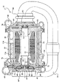
[0018]本発明は、単段および多段の電気モーター駆動圧縮機を含む、様々なタイプの電気モーター駆動圧縮機に応用することができる。本発明の原理を説明することを目的として本明細書において説明される具体的な実施形態は、連続して配置された2つの遠心圧縮機を有する直列二段圧縮機であるが、本発明は、並列二段圧縮機や他のタイプの圧縮機にも適用することができる。したがって、燃料電池(プロトン交換膜(PEM)燃料電池など)で使用するための直列二段電気モーター駆動圧縮機10の簡易断面図が、図1に示される。二段圧縮機10は、モーターハウジング20と、モーターハウジングの一方の端部に取り付けられた低圧圧縮機ハウジング40と、モーターハウジングの他方の端部に取り付けられた高圧圧縮機ハウジング60とを備える、ハウジング組立体を含む。モーターハウジング20は、モーター固定子22と、軸26を有するモーター回転子24とを内蔵し、軸26の周りには永久磁石28がしっかりと取り付けられている。モーターハウジング20は、モーター回転子24および軸26が貫通する穴30を画定する。空気軸受32がモーターハウジング20内に配置されて、回転子24および軸26を回転可能に支持する。
[0018] The present invention can be applied to various types of electric motor driven compressors, including single and multi-stage electric motor driven compressors. While the specific embodiments described herein for purposes of illustrating the principles of the invention are series two-stage compressors having two centrifugal compressors arranged in series, the invention is It can also be applied to parallel two-stage compressors and other types of compressors. Thus, a simplified cross-sectional view of a series two-stage electric motor driven
[0019]低圧圧縮機ハウジング40は、軸26の一方の端部に取り付けられて軸26と一緒に回転する遠心低圧圧縮機翼車42を内蔵し、低圧圧縮機ハウジングはまた、低圧圧縮機翼車に空気を導く空気吸入口44と、低圧圧縮機翼車を通過しそれによって圧縮された圧縮空気を集める低圧渦形室46とを含む、低圧圧縮機流れ経路を画定する。低圧圧縮機はまた、圧縮空気を低圧圧縮機翼車42から低圧渦形室46内に導き、かつ、渦形室に入っていく空気の速度を低減させて静圧を高める働きをする、ディフューザ45を含む。
[0019] The low
[0020]高圧圧縮機ハウジング60は、軸26の反対側の端部に取り付けられて軸26と一緒に回転する、遠心高圧圧縮機翼車62を内蔵する。高圧圧縮機ハウジングは、高圧圧縮機翼車に空気を導く空気吸入口64と、高圧圧縮機翼車を通過しそれによって圧縮された圧縮空気を集める高圧渦形室66とを含む、高圧圧縮機流れ経路を画定する。高圧圧縮機はまた、圧縮空気を高圧圧縮機翼車62から高圧渦形室66内に導き、かつ、渦形室に入っていく空気の速度を低減させて静圧を高める働きをする、ディフューザ65を含む。
[0020] The high
[0021]圧縮機は、圧縮空気を低圧渦形室46から高圧圧縮機へ循環させて第2段階の圧縮過程でさらに加圧するための、低圧渦形室46と高圧圧縮機の吸入口64との間に接続された段間導管50をさらに含む。
[0021] The compressor circulates compressed air from the low
[0022]冷却空気通路がハウジング組立体内に画定されて、空気軸受32に冷却空気を供給する。具体的には、図2を参照すると、冷却空気は、モーターハウジング20に画定された冷却空気供給入口70内に供給される。例えば、圧縮機10が車両用の燃料電池システムで使用される場合、高圧渦形室66からの圧縮空気は、燃料電池に供給される前に空気を冷却するための車両の熱交換器に通されるが、熱交換器から出る空気の一部分が、取り出されて冷却空気供給入口70内に供給されうる。そこから、冷却空気は、モーターハウジング20および低圧圧縮機ハウジング40により協働的に画定されたアニュラス部72に入る。アニュラス部72内の冷却空気の一部分は、通路73を通じて径方向内方に向けられて、低圧側空気スラスト軸受のためのスラスト板43の両側に供給される。スラスト板43の内(モーター)側にある空気は、ジャーナル空気軸受32に供給され(また、回転子の磁石28を冷却し)、次いで、モーター空隙内に排出される。スラスト板43の外側にある空気は、通路47を通じて、圧縮機ハウジングに画定された環状空間49内へと径方向外方に進み、そしてそこから通路51を通じて、モーター空隙内へと進む。
[0022] A cooling air passage is defined in the housing assembly to supply cooling air to the
[0023]アニュラス部72内の冷却空気の残りの部分は、軸方向に延在する冷却空気導管74を通るように向けられ、この冷却空気導管74は、アニュラス部72からモーターハウジング20を貫通して延在して、高圧圧縮機の領域内のさらなるアニュラス部76(図1および3)に接続する。図3を参照すると、モーターハウジング20は、アニュラス部76からモーター回転子24の高圧側端部に位置する全体的に環状の空間80内へと概ね径方向内方に通じる、冷却空気通路78を画定する。全体的に環状の空間80内に供給された冷却空気は、概ね軸方向に(図3では左に)進んで、回転子24のためのジャーナル空気軸受32に供給され(また、回転子の磁石28を冷却し)、次いで、モーター空隙内に排出される。
[0023] The remaining portion of the cooling air in the
[0024]モーター空隙内の冷却空気は、ポート71を介してモーター空隙から排出され、このポート71は、導管71aを介してハウジング排出ポート71b(図1)に接続されている。
[0024] Cooling air in the motor air gap is exhausted from the motor air gap via
[0025]次に図3を参照すると、高圧圧縮機は、高圧圧縮機ハウジング60およびモーターハウジング20とは別に形成されてそれらの間に配置された、全体的に環状の遮熱材100を含む。具体的には、遮熱材100は、その径方向外周にフランジ102を有し、このフランジ102は、径方向に関して、圧縮機ハウジング60のフランジ68とモーターハウジング20の肩21と間に配置され、また、遮熱材を径方向に拘束するように、フランジ68と肩21との間に挟まれる。遮熱材のフランジ102は、モーターハウジングのフランジ23とHP圧縮機ハウジング60上の肩67との間に捕捉されかつ軸方向に拘束される。Vバンドクランプ35が、モーターハウジングのフランジ23およびHP圧縮機ハウジングのフランジ68をまとめて挟持し、それにより、HP圧縮機ハウジングの肩67と遮熱材のフランジ102との間に配置された密閉リング69が、それらの部分の間で軸方向に圧縮され、それにより、遮熱材と圧縮機ハウジングとの接合部分が密閉される。遮熱材100は、径方向に向けられた壁部分104を含み、この壁部分104は、フランジ102から径方向内方に延在し、かつ、HP渦形室66内に送達される圧縮空気のためのディフューザ65の一方の壁を画定し、ディフューザの反対側の壁は、HP圧縮機ハウジング60によって画定されている。
[0025] Referring now to FIG. 3, the high pressure compressor includes a generally
[0026]引き続き図3を参照すると、前述の冷却空気アニュラス部76は、遮熱材100およびモーターハウジング20により協働的に画定されている。モーターハウジング内の冷却空気通路78は、アニュラス部76から径方向内方に延在して空間80内に冷却空気を供給し、空間80から前述のジャーナル軸受に空気が供給される。したがって、遮熱材100は、ハウジング組立体と協働して、空気軸受に供給される冷却空気のための冷却空気通路の一部を画定する。
With continued reference to FIG. 3, the aforementioned
[0027]遮熱材100はまた、高温のモーターハウジング20から高圧圧縮機を通過する空気への熱伝達を最小限に抑えるのに役立つ。この目的のために、モーターハウジング20は、遮熱材100とは少ししか接触しない。モーターハウジング20は、固定子22の周りのハウジングに冷却液を循環させるための冷却液通路25を画定する。モーターハウジング20とHP圧縮機ハウジング60との間に捕捉された遮熱材の取付フランジ102は、取付フランジからモーターハウジングの一部分への熱伝達を促進するために、冷却液通路25内の冷却液によって冷却されるモーターハウジングの前述の部分と接触する(図3における冷却液通路25に対するフランジ102の近接近性に留意されたい)。遮熱材100とモーターハウジング20との間には、空気ギャップ77も存在する。アニュラス部76からの空気は、この片側が塞がった(dead−headed)空気ギャップ77に過給される。これらの特徴の全てが、遮熱材を介したモーターハウジングからHP圧縮機内の圧縮されている空気への熱伝達を最小限に抑えることに寄与する。
[0027] The
[0028]遮熱材100はその上、さらに別の機能、すなわち、HP圧縮機排気をHPジャーナル軸受から実質的に隔絶するシールのための密閉面を提供する機能を果たす。したがって、圧縮機は、HP圧縮機翼車62と空気ジャーナル軸受32との中間の位置で軸26の周りに固定された、シール担体63を含む。シールリング63aが、シール担体63の周りに形成された円周溝内に係合され、また、シールリングは、HP圧縮機流れ経路からジャーナル空気軸受への空気漏れを防ぐために、遮熱材100の径方向内側表面(図3)に接触して密閉するように位置決めされる。示された実施形態では、密閉状態をさらに向上させるために、シール担体63にある第2の溝内に、第2のシールリング63bも存在する。
[0028] The
[0029]本発明は電気モーター駆動二段直列圧縮機を参照して説明されたが、本発明は、単段圧縮機などの他の電気モーター駆動圧縮機に適用することもできる。添付の特許請求の範囲において、「第1の圧縮機翼車」への言及は、二段直列圧縮機のHP圧縮機翼車(この場合、「第2の圧縮機翼車」はLP圧縮機翼車である)か、または単段圧縮機における圧縮機翼車に当てはまるものとして理解されるべきである。 [0029] Although the present invention has been described with reference to an electric motor driven two-stage series compressor, the present invention can also be applied to other electric motor driven compressors such as a single stage compressor. In the appended claims, reference to “first compressor wheel” refers to a two-stage series compressor HP compressor wheel (in this case, “second compressor wheel” refers to an LP compressor). It is to be understood that this applies to a compressor wheel in a single stage compressor.
[0030]上記の説明および関連する図面に提示された教示の便益を有する当業者には、本明細書で説明された本発明の多くの修正形態および他の実施形態が思い浮かぶであろう。したがって、本発明は開示された特定の実施形態およびその修正形態に限定されるものではなく、また、他の実施形態が添付の特許請求の範囲に記載の範囲に含まれるように意図されていることが、理解されるべきである。本明細書において具体的な用語が用いられたが、これらの用語は包括的かつ記述的な意味で使用されたものに過ぎず、限定を目的としたものではない。 [0030] Many modifications and other embodiments of the invention described herein will occur to those skilled in the art having the benefit of the teachings presented in the foregoing descriptions and the associated drawings. Accordingly, the invention is not limited to the specific embodiments disclosed and modifications thereof, and other embodiments are intended to be included within the scope of the appended claims. It should be understood. Although specific terms are used herein, these terms are used in a comprehensive and descriptive sense only and are not intended to be limiting.
10 直列二段電気モーター駆動圧縮機、二段圧縮機
20 モーターハウジング
21 肩
22 モーター固定子
23 フランジ
24 モーター回転子
25 冷却液通路
26 軸
28 永久磁石
30 穴
32 空気軸受、ジャーナル空気軸受、空気ジャーナル軸受
35 Vバンドクランプ
40 低圧圧縮機ハウジング
42 遠心低圧圧縮機翼車
43 スラスト板
44 空気吸入口
45 ディフューザ
46 低圧渦形室
47 通路
49 環状空間
50 段間導管
51 通路
60 高圧圧縮機ハウジング
62 遠心高圧圧縮機翼車
63 シール担体
63a シールリング
63b 第2のシールリング
64 空気吸入口
65 ディフューザ
66 高圧渦形室
67 肩
68 フランジ
69 密閉リング
70 冷却空気供給入口
71 ポート
71a 導管
71b ハウジング排出ポート
72 アニュラス部
73 通路
74 冷却空気導管
76 アニュラス部
77 空気ギャップ
78 冷却空気通路
80 全体的に環状の空間
100 遮熱材
102 フランジ、取付フランジ
104 壁部分
DESCRIPTION OF
Claims (7)
モーターハウジング、および前記モーターハウジングの一方の端部に取り付けられた第1の圧縮機ハウジングを含むハウジング組立体であって、前記モーターハウジングが、モーター固定子、および軸を有するモーター回転子を内蔵し、前記モーターハウジングが、前記モーター回転子および前記軸が貫通する穴を画定する、ハウジング組立体を備え、
前記第1の圧縮機ハウジングが、前記軸の一方の端部に取り付けられて前記軸と一緒に回転する第1の遠心圧縮機翼車を内蔵し、前記第1の圧縮機ハウジングがまた、前記第1の圧縮機翼車に空気を導く第1の空気吸入口と、前記第1の圧縮機翼車を通されそれによって圧縮された圧縮空気を集める第1の渦形室とを含む、第1の圧縮機流れ経路を画定し、前記電気モーター駆動圧縮機がさらに、
前記第1の圧縮機翼車の出口と前記第1の渦形室との間の第1のディフューザであって、前記圧縮空気をより低い速度に拡散しかつ前記圧縮空気を前記渦形室内に送達する働きをする、第1のディフューザと、
前記モーターハウジング内に配置されて前記軸を回転可能に支持する、空気軸受と、
前記空気軸受に冷却空気を供給するための、前記ハウジング組立体内に画定された冷却空気通路と、
前記第1の圧縮機ハウジングおよび前記モーターハウジングとは別に形成されてそれらの間に配置された遮熱材であって、前記第1の渦形室内に送達される前記圧縮空気のための前記第1のディフューザの一方の壁を画定し、また、前記ハウジング組立体と協働して、前記空気軸受に供給される前記冷却空気のための前記冷却空気通路の一部を画定する、遮熱材と
を備え、
前記モーターハウジングが、冷却液を循環させるための冷却液通路を画定し、前記遮熱材が、前記モーターハウジングと前記第1の圧縮機ハウジングとの間に捕捉される取付フランジを画定し、前記取付フランジが、前記取付フランジから前記モーターハウジングの一部分への熱伝達を促進するために、前記冷却液によって冷却される前記モーターハウジングの前記部分と接触する、
電気モーター駆動圧縮機。 An electric motor driven compressor,
A housing assembly including a motor housing and a first compressor housing attached to one end of the motor housing, the motor housing incorporating a motor stator having a motor stator and a shaft. The motor housing comprises a housing assembly defining a hole through which the motor rotor and the shaft pass;
The first compressor housing incorporates a first centrifugal compressor wheel that is attached to one end of the shaft and rotates with the shaft, the first compressor housing also comprising the first compressor housing A first air inlet for directing air to the first compressor wheel, and a first spiral chamber for collecting compressed air that is passed through the first compressor wheel and compressed thereby. One compressor flow path, the electric motor driven compressor further comprising:
A first diffuser between the outlet of the first compressor wheel and the first vortex chamber, diffusing the compressed air at a lower velocity and allowing the compressed air to enter the vortex chamber; A first diffuser that serves to deliver;
An air bearing disposed within the motor housing and rotatably supporting the shaft;
A cooling air passage defined in the housing assembly for supplying cooling air to the air bearing;
A heat shield formed separately from and disposed between the first compressor housing and the motor housing, wherein the first for the compressed air delivered into the first spiral chamber; A heat shield that defines one wall of a diffuser and, in cooperation with the housing assembly, defines a portion of the cooling air passage for the cooling air supplied to the air bearing. It equipped with a door,
The motor housing defines a coolant passage for circulating a coolant, and the heat shield defines a mounting flange that is captured between the motor housing and the first compressor housing; A mounting flange contacts the portion of the motor housing that is cooled by the coolant to facilitate heat transfer from the mounting flange to a portion of the motor housing;
Electric motor driven compressor.
Applications Claiming Priority (2)
| Application Number | Priority Date | Filing Date | Title |
|---|---|---|---|
| US14/226,309 US9732766B2 (en) | 2014-02-19 | 2014-03-26 | Electric motor-driven compressor having a heat shield forming a wall of a diffuser |
| US14/226,309 | 2014-03-26 |
Publications (2)
| Publication Number | Publication Date |
|---|---|
| JP2015187444A JP2015187444A (en) | 2015-10-29 |
| JP6579649B2 true JP6579649B2 (en) | 2019-09-25 |
Family
ID=52807532
Family Applications (1)
| Application Number | Title | Priority Date | Filing Date |
|---|---|---|---|
| JP2015060766A Active JP6579649B2 (en) | 2014-03-26 | 2015-03-24 | Electric motor driven compressor with a heat shield that forms the wall of the diffuser |
Country Status (4)
| Country | Link |
|---|---|
| US (1) | US9732766B2 (en) |
| EP (1) | EP2924294B1 (en) |
| JP (1) | JP6579649B2 (en) |
| CN (1) | CN104948478B (en) |
Families Citing this family (21)
| Publication number | Priority date | Publication date | Assignee | Title |
|---|---|---|---|---|
| CN105829733B (en) * | 2014-02-13 | 2019-03-26 | 三菱重工发动机和增压器株式会社 | Multi-stage motor centrifugal compressor |
| EP3112686A4 (en) * | 2014-02-25 | 2017-01-04 | Mitsubishi Heavy Industries, Ltd. | Multistage electric centrifugal compressor and supercharging system of internal combustion engine |
| CN106286338A (en) * | 2015-06-02 | 2017-01-04 | 上海优耐特斯压缩机有限公司 | The structure that the centrifugal compressor leakage air using high-speed electric expreess locomotive is cooled down |
| FR3045111B1 (en) * | 2015-12-14 | 2017-12-01 | Labinal Power Systems | ELECTRIC CENTRIFUGAL COMPRESSOR OF TURBOMACHINE OR AIRCRAFT |
| FR3049661B1 (en) * | 2016-03-22 | 2020-10-09 | Valeo Systemes De Controle Moteur | ELECTRIC COMPRESSOR WITH BEARING PROTECTION SYSTEM |
| JP2017172444A (en) * | 2016-03-23 | 2017-09-28 | 株式会社豊田自動織機 | Electric compressor and cooling system |
| FR3052507B1 (en) * | 2016-06-08 | 2020-10-09 | Valeo Systemes De Controle Moteur | ELECTRIC COMPRESSOR WITH BEARING PROTECTION SYSTEM |
| JP6756382B2 (en) | 2017-01-25 | 2020-09-16 | 株式会社Ihi | Electric compressor |
| CN107664143B (en) * | 2017-10-16 | 2023-10-27 | 珠海格力电器股份有限公司 | Compressor and air conditioner with same |
| JP6944853B2 (en) * | 2017-11-15 | 2021-10-06 | 株式会社マーレ フィルターシステムズ | Electric compressor |
| DE102018108828A1 (en) * | 2018-04-13 | 2019-10-17 | Trumpf Schweiz Ag | centrifugal blower |
| CN111365254A (en) * | 2018-12-25 | 2020-07-03 | 珠海格力电器股份有限公司 | Compressor for optimizing internal space |
| CN111365286A (en) * | 2018-12-25 | 2020-07-03 | 珠海格力电器股份有限公司 | Diffuser with air supply channel, compressor and air conditioner |
| CN111271304B (en) * | 2020-02-27 | 2021-10-08 | 海德韦尔(太仓)能源科技有限公司 | Centrifugal air compressor with double cooling systems |
| US20210310371A1 (en) * | 2020-04-07 | 2021-10-07 | Garrett Transportation I Inc | Motorized compressor device with air bearing having reduced axial and radial stack-up |
| CN112983849B (en) * | 2021-02-10 | 2022-04-05 | 西安交通大学 | Centrifugal compressor structure with axial force capable of being automatically balanced |
| CN112879318B (en) * | 2021-04-02 | 2021-09-14 | 烟台东德实业有限公司 | High-speed centrifugal compressor |
| CN113606162A (en) * | 2021-09-06 | 2021-11-05 | 北京昆腾迈格技术有限公司 | Energy-saving hydrogen circulating pump |
| JP2023119769A (en) | 2022-02-17 | 2023-08-29 | 株式会社豊田自動織機 | Turbo type fluid machine |
| WO2023162160A1 (en) * | 2022-02-25 | 2023-08-31 | 三菱重工エンジン&ターボチャージャ株式会社 | Electric compressor |
| CN114645859A (en) * | 2022-05-02 | 2022-06-21 | 烟台东德实业有限公司 | Bilateral two-stage high-speed centrifugal air compressor and expander integrated system |
Family Cites Families (15)
| Publication number | Priority date | Publication date | Assignee | Title |
|---|---|---|---|---|
| US4068612A (en) | 1976-01-26 | 1978-01-17 | M & W Gear Company | Turbocharger housing construction for marine turbocharger and device for turbocharging a marine engine |
| US5020319A (en) | 1987-06-09 | 1991-06-04 | Ngk Spark Plug Co., Ltd. | Hollow heat-resisting body assembly for internal combustion engine |
| JPH03212137A (en) * | 1990-01-11 | 1991-09-17 | Toshiba Corp | Claw pole type synchronous generator |
| JPH08335731A (en) * | 1995-06-06 | 1996-12-17 | Fanuc Ltd | Air blower in gas laser system |
| JP3799121B2 (en) * | 1997-03-19 | 2006-07-19 | 株式会社 日立インダストリイズ | 2-stage centrifugal compressor |
| GB2335710A (en) | 1998-03-27 | 1999-09-29 | Aisin Seiki | Hybrid turbocharger with air bearings |
| DE59809488D1 (en) * | 1998-05-25 | 2003-10-09 | Abb Turbo Systems Ag Baden | centrifugal compressors |
| JP4474707B2 (en) * | 1998-12-25 | 2010-06-09 | ダイキン工業株式会社 | Turbo compressor |
| US6422838B1 (en) | 2000-07-13 | 2002-07-23 | Flowserve Management Company | Two-stage, permanent-magnet, integral disk-motor pump |
| US7063519B2 (en) * | 2002-07-02 | 2006-06-20 | R & D Dynamics Corporation | Motor driven centrifugal compressor/blower |
| US6997686B2 (en) * | 2002-12-19 | 2006-02-14 | R & D Dynamics Corporation | Motor driven two-stage centrifugal air-conditioning compressor |
| CN100545462C (en) | 2003-05-20 | 2009-09-30 | 东芝泰格有限公司 | Electric blowing machine and electrical equipment with this electric blowing machine |
| DE102004023148A1 (en) * | 2004-05-07 | 2005-11-24 | Atlas Copco Energas Gmbh | Turbomachinery for low temperature applications |
| GB2427248B (en) | 2005-06-16 | 2010-10-06 | Malcolm George Leavesley | Turbocharger apparatus having a bearing housing with an integral heat shield |
| US7758320B2 (en) | 2007-05-03 | 2010-07-20 | Tank, Inc. | Two-stage hydrodynamic pump and method |
-
2014
- 2014-03-26 US US14/226,309 patent/US9732766B2/en active Active
-
2015
- 2015-03-10 EP EP15158472.9A patent/EP2924294B1/en active Active
- 2015-03-24 JP JP2015060766A patent/JP6579649B2/en active Active
- 2015-03-25 CN CN201510132046.3A patent/CN104948478B/en active Active
Also Published As
| Publication number | Publication date |
|---|---|
| EP2924294B1 (en) | 2019-05-29 |
| JP2015187444A (en) | 2015-10-29 |
| CN104948478B (en) | 2019-04-16 |
| US9732766B2 (en) | 2017-08-15 |
| CN104948478A (en) | 2015-09-30 |
| EP2924294A2 (en) | 2015-09-30 |
| US20150275920A1 (en) | 2015-10-01 |
| EP2924294A3 (en) | 2015-10-28 |
Similar Documents
| Publication | Publication Date | Title |
|---|---|---|
| JP6579649B2 (en) | Electric motor driven compressor with a heat shield that forms the wall of the diffuser | |
| EP3483450B1 (en) | Multi-stage compressor with turbine section for fuel cell system | |
| JP6671858B2 (en) | Electric motor driven compressor with bidirectional coolant passage | |
| CN112983848B (en) | Fuel cell stack and gas supply device | |
| JP7042265B2 (en) | Turbo compressor with separate cooling air passages | |
| US11177489B2 (en) | Centrifugal compressor with diffuser | |
| JP5738869B2 (en) | Turbo molecular pump | |
| WO2016067978A1 (en) | Exhaust apparatus and gas turbine | |
| CN112780583B (en) | Fuel cell stack and two-stage centrifugal compressor | |
| US11221012B2 (en) | Turbo fluid machine | |
| JP2014111905A (en) | Centrifugal compressor and supercharger with the same, and operation method for centrifugal compressor | |
| US11261879B2 (en) | Fluid machine | |
| JP2013245655A (en) | Variable nozzle unit and variable displacement type supercharger | |
| CN112503025A (en) | Air compressor and vehicle | |
| DK2751429T3 (en) | TURBO COMPRESSOR AND USE. | |
| JP2001123997A (en) | Centrifugal compressor with magnetic bearing | |
| JP2013253521A (en) | Variable nozzle unit and variable capacity type supercharger | |
| JP2020133577A (en) | Compressor | |
| CN110541831A (en) | Multi-stage compressor with turbine section for a fuel cell system | |
| CN111271304A (en) | Centrifugal air compressor with double cooling systems | |
| CN108292874A (en) | Motor supporting device, compressor and booster | |
| JP2013185472A (en) | Scroll type fluid machine | |
| JP2023172660A (en) | Electric fluid machinery | |
| JP2023544342A (en) | Radial compressors and how to operate a radial compressor | |
| KR20010026716A (en) | Structure for cooling motor in turbo compressor |
Legal Events
| Date | Code | Title | Description |
|---|---|---|---|
| A621 | Written request for application examination |
Free format text: JAPANESE INTERMEDIATE CODE: A621 Effective date: 20180316 |
|
| A711 | Notification of change in applicant |
Free format text: JAPANESE INTERMEDIATE CODE: A711 Effective date: 20180725 |
|
| A977 | Report on retrieval |
Free format text: JAPANESE INTERMEDIATE CODE: A971007 Effective date: 20190214 |
|
| A131 | Notification of reasons for refusal |
Free format text: JAPANESE INTERMEDIATE CODE: A131 Effective date: 20190220 |
|
| A521 | Request for written amendment filed |
Free format text: JAPANESE INTERMEDIATE CODE: A523 Effective date: 20190513 |
|
| TRDD | Decision of grant or rejection written | ||
| A01 | Written decision to grant a patent or to grant a registration (utility model) |
Free format text: JAPANESE INTERMEDIATE CODE: A01 Effective date: 20190821 |
|
| A61 | First payment of annual fees (during grant procedure) |
Free format text: JAPANESE INTERMEDIATE CODE: A61 Effective date: 20190823 |
|
| R150 | Certificate of patent or registration of utility model |
Ref document number: 6579649 Country of ref document: JP Free format text: JAPANESE INTERMEDIATE CODE: R150 |
|
| R250 | Receipt of annual fees |
Free format text: JAPANESE INTERMEDIATE CODE: R250 |
|
| R250 | Receipt of annual fees |
Free format text: JAPANESE INTERMEDIATE CODE: R250 |