JP6571052B2 - Small excavator - Google Patents

Small excavator Download PDF

Info

Publication number
JP6571052B2
JP6571052B2 JP2016148452A JP2016148452A JP6571052B2 JP 6571052 B2 JP6571052 B2 JP 6571052B2 JP 2016148452 A JP2016148452 A JP 2016148452A JP 2016148452 A JP2016148452 A JP 2016148452A JP 6571052 B2 JP6571052 B2 JP 6571052B2
Authority
JP
Japan
Prior art keywords
frame
center
turning
swivel
control valve
Prior art date
Legal status (The legal status is an assumption and is not a legal conclusion. Google has not performed a legal analysis and makes no representation as to the accuracy of the status listed.)
Active
Application number
JP2016148452A
Other languages
Japanese (ja)
Other versions
JP2018017033A5 (en
JP2018017033A (en
Inventor
大輔 岡
大輔 岡
木村 庄吾
庄吾 木村
一樹 松廣
一樹 松廣
Current Assignee (The listed assignees may be inaccurate. Google has not performed a legal analysis and makes no representation or warranty as to the accuracy of the list.)
Hitachi Construction Machinery Tierra Co Ltd
Original Assignee
Hitachi Construction Machinery Tierra Co Ltd
Priority date (The priority date is an assumption and is not a legal conclusion. Google has not performed a legal analysis and makes no representation as to the accuracy of the date listed.)
Filing date
Publication date
Application filed by Hitachi Construction Machinery Tierra Co Ltd filed Critical Hitachi Construction Machinery Tierra Co Ltd
Priority to JP2016148452A priority Critical patent/JP6571052B2/en
Publication of JP2018017033A publication Critical patent/JP2018017033A/en
Publication of JP2018017033A5 publication Critical patent/JP2018017033A5/ja
Application granted granted Critical
Publication of JP6571052B2 publication Critical patent/JP6571052B2/en
Active legal-status Critical Current
Anticipated expiration legal-status Critical

Links

Images

Description

本発明は、市街地等の狭い作業現場での掘削作業に好適に用いられる小型油圧ショベルに関し、特に、油圧アクチュエータを制御する制御弁群が上部旋回体のオペレータの居住領域の下方に設けられた小型油圧ショベルに関する。   The present invention relates to a small hydraulic excavator that is suitably used for excavation work in a narrow work site such as an urban area, and in particular, a small hydraulic valve in which a control valve group for controlling a hydraulic actuator is provided below a living area of an operator of an upper swing body. It relates to hydraulic excavators.

一般に、市街地等の狭い作業現場での掘削作業には、ミニショベルと呼ばれる小型油圧ショベルが好適に用いられる。この小型油圧ショベルは、建物の内部の解体作業、街路等の狭い場所での掘削作業に用いられるため、例えばミニショベルの中でも小型の機械重量が0.8〜4トン程度に設定されている。   In general, a small hydraulic excavator called a mini excavator is suitably used for excavation work in a narrow work site such as an urban area. Since this small hydraulic excavator is used for dismantling work inside a building and excavation work in a narrow place such as a street, a small mechanical weight is set to about 0.8 to 4 tons among mini excavators, for example.

ここで、小型油圧ショベルは、下部走行体と、下部走行体上に旋回装置を介して支持された上部旋回体と、上部旋回体の前側に俯仰動可能に設けられたフロント装置と、上部旋回体の後側に位置してフロント装置との重量バランスをとるためのカウンタウエイトとを含んで構成されている。   Here, the small hydraulic excavator includes a lower traveling body, an upper swinging body supported on the lower traveling body via a swinging device, a front device provided on the front side of the upper swinging body so as to be able to move up and down, and an upper swinging A counterweight is provided on the rear side of the body to balance the weight with the front device.

小型油圧ショベルとしては、上部旋回体を旋回動作させたときに、上部旋回体とフロント装置とが、下部走行体の車幅寸法と下部走行体の前,後方向の長さ寸法とに収まるように構成された超小旋回型の小型油圧ショベルも知られている。超小旋回型の小型油圧ショベルは、通常、側溝掘り作業等に用いるオフセットフロント装置を備えている。このオフセットフロント装置は、ロアブームとアッパブームとを有し、アーム支持体を介してアッパブームに取付けられたアームが、ロアブームに対して左,右方向に平行移動する構成となっている。   As a small hydraulic excavator, when the upper swinging body is swung, the upper swinging body and the front device fit within the vehicle width dimension of the lower traveling body and the length dimension in the front and rear directions of the lower traveling body. There is also known an ultra-small swivel type small hydraulic excavator constructed as described above. An ultra-small swivel type hydraulic excavator is usually provided with an offset front device used for side grooving work or the like. This offset front device has a lower boom and an upper boom, and an arm attached to the upper boom via an arm support is configured to translate in the left and right directions with respect to the lower boom.

オフセットフロント装置は、ロアブームを大きく仰動させると共にアームをロアブーム側に折り畳むことにより、超小旋回姿勢をとることができる。この超小旋回姿勢では、上部旋回体を旋回させたときに、上部旋回体とオフセットフロント装置とが下部走行体の幅寸法と前,後方向の長さ寸法内で全旋回することができる。従って、超小旋回型の小型油圧ショベルは、市街地等の狭い作業現場においても、上部旋回体とオフセットフロント装置とが周囲の障害物に接触することなく、円滑に旋回動作を行うことができ、オフセットフロント装置を用いて側溝掘り作業等を効率良く行うことができる。   The offset front device can take a very small turning posture by largely raising the lower boom and folding the arm to the lower boom side. In this ultra-small turning posture, when the upper turning body is turned, the upper turning body and the offset front device can fully turn within the width dimension of the lower traveling body and the length dimension in the front and rear directions. Therefore, the ultra-small turning type small hydraulic excavator can smoothly perform the turning operation without contacting the surrounding obstacle with the upper turning body and the offset front device even in a narrow work site such as an urban area. Side gutter work or the like can be performed efficiently using the offset front device.

超小旋回型の小型油圧ショベルの上部旋回体を構成する旋回フレームは、旋回装置の旋回輪が取付けられたセンタフレームと、上部旋回体の旋回中心よりも左,右方向の右側に片寄ってセンタフレーム上に立設された左,右の縦板とを有している。各縦板の前側は、オフセットフロント装置を構成するロアブームのフート部が取付けられるブラケットとなっている。また、各縦板の後側には、上部旋回体の旋回中心よりも後側に位置して横板が設けられ、この横板は、左縦板よりも左側に延びている。   The swing frame that constitutes the upper swing body of the ultra-small swing type small hydraulic excavator has a center frame to which the swing wheel of the swing device is mounted, and a center that is offset to the right in the left and right directions from the swing center of the upper swing body. It has left and right vertical plates standing on the frame. The front side of each vertical plate is a bracket to which the foot part of the lower boom constituting the offset front device is attached. In addition, a lateral plate is provided on the rear side of each vertical plate so as to be located behind the pivot center of the upper revolving unit, and this lateral plate extends to the left side of the left vertical plate.

一方、センタフレームには、旋回装置の旋回輪を取付けるための旋回輪取付孔群が旋回中心を中心として円形状に列設されている。この上で、センタフレームの旋回輪取付孔群による円の内側には、旋回装置の旋回モータを挿通するための旋回モータ挿通孔が、左縦板から左側に離間し、かつ旋回中心よりも前側に位置して穿設されている。さらに、センタフレーム上には、旋回モータ挿通孔を取囲む位置に、旋回モータが取付けられる旋回モータ取付座が固着されている。   On the other hand, in the center frame, a swivel ring mounting hole group for mounting a swivel wheel of a swivel device is arranged in a circular shape centering on the swivel center. On this side, a turning motor insertion hole for inserting the turning motor of the turning device is spaced from the left vertical plate to the left side and is further forward than the turning center. It is drilled in the position. Further, a turning motor mounting seat to which the turning motor is attached is fixed on the center frame at a position surrounding the turning motor insertion hole.

ここで、小型油圧ショベルは、一般的なトラックに積んで搬送できるように、小型化、軽量化する必要がある。そこで、小型油圧ショベルには、旋回装置が取付けられるセンタフレームだけを厚板で形成することにより、旋回フレームの軽量化を図るようにしたものがある(特許文献1参照)。   Here, the small hydraulic excavator needs to be reduced in size and weight so that it can be carried on a general truck. Therefore, some small hydraulic excavators are designed to reduce the weight of the turning frame by forming only the center frame to which the turning device is attached from a thick plate (see Patent Document 1).

特開2006−193914号公報JP 2006-193914 A

ところで、特許文献1によるものでは、旋回フレームを構成する構造体のうち、センタフレームの板厚寸法だけを厚くしている。このため、センタフレームの周囲の部材の強度を高めるために旋回フレームには新たな補強が必要になるから、旋回フレームの重量が増大するという問題がある。   By the way, in the thing by patent document 1, only the plate | board thickness dimension of a center frame is thickened among the structures which comprise a turning frame. For this reason, in order to raise the intensity | strength of the member around a center frame, since a new reinforcement is needed for a turning frame, there exists a problem that the weight of a turning frame increases.

本発明は上述した従来技術の問題に鑑みなされたもので、本発明の目的は、旋回フレームの強度を高めると共に、旋回フレームを軽量化できるようにした小型油圧ショベルを提供することにある。   The present invention has been made in view of the above-described problems of the prior art, and an object of the present invention is to provide a compact hydraulic excavator that can increase the strength of the revolving frame and reduce the weight of the revolving frame.

本発明は、下部走行体と、前記下部走行体に旋回装置を介して支持された上部旋回体と、前記上部旋回体に俯仰動可能に設けられたオフセットフロント装置と、前記上部旋回体の後側に位置して前記オフセットフロント装置との重量バランスをとるためのカウンタウエイトとからなり、前記上部旋回体の旋回フレームは、前記旋回装置の旋回輪が取付けられるセンタフレームと、前記上部旋回体の旋回中心よりも右側に片寄って前記センタフレーム上に立設され前側に前記オフセットフロント装置が取付けられるブラケットを有している左,右の縦板と、前記上部旋回体の旋回中心よりも後側に位置して前記左縦板よりも左側に延びた横板と、前記センタフレームに前記旋回中心を中心として円形状に列設され前記旋回装置の旋回輪を取付けるための旋回輪取付孔群と、前記旋回装置の旋回モータを挿通するために前記旋回輪取付孔群による円の内側で前記左縦板から左側に離間し、かつ前記旋回中心よりも前側に穿設された旋回モータ挿通孔と、前記旋回モータ挿通孔を取囲んで前記センタフレーム上に固着され前記旋回モータが取付けられる旋回モータ取付座とを含んで構成され、前記上部旋回体および前記オフセットフロント装置は、前記下部走行体の車幅内で旋回可能な超小旋回型の小型油圧ショベルに適用される。   The present invention relates to a lower traveling body, an upper swinging body supported by the lower traveling body via a swinging device, an offset front device provided on the upper swinging body so as to be able to move up and down, and a rear of the upper swinging body. And a counterweight for balancing the weight with the offset front device, and the swing frame of the upper swing body includes a center frame to which the swing wheel of the swing device is attached, and the upper swing body Left and right vertical plates that have brackets that are erected on the center frame and are mounted on the front side so as to be shifted to the right side of the turning center, and the rear side of the turning center of the upper turning body A horizontal plate located on the left side of the left vertical plate and extending in a circular shape around the turning center is attached to the center frame. A swivel wheel mounting hole group, and a left side from the left vertical plate inside the circle formed by the swivel wheel mounting hole group in order to insert the swivel motor of the swivel device, and drilled in front of the swivel center. The swing motor insertion hole provided, and a swing motor mounting seat that surrounds the swing motor insertion hole and is fixed on the center frame and to which the swing motor is mounted. The upper swing body and the offset front The apparatus is applied to an ultra-small turning type small hydraulic excavator capable of turning within the vehicle width of the lower traveling body.

本発明が採用する構成の特徴は、前記旋回フレームのセンタフレームは、前記旋回輪取付孔群よりも左側で前記横板よりも前側が切欠かれた切欠部位となっており、前記左縦板よりも左側で前記横板よりも前側には、前記センタフレームと前記切欠部位の上側に位置する取付台上に制御弁群が取付けられている制御弁ユニットが設けられており、前記制御弁ユニットの上側位置には、前記カウンタウエイトとの間にオペレータが居住する居住領域が設けられており、前記上部旋回体の前記旋回中心、前記旋回モータおよび前記制御弁ユニットの重心位置を通る斜めの直線に沿うように前記切欠部位を左斜め前側に延びると共に基端側が前記センタフレームに取付けられ先端側が自由端となった傾斜フレームが設けられており、前記制御弁ユニットの前記取付台は、左前側部位が前記傾斜フレームに支持されたことにある。

A feature of the configuration adopted by the present invention is that the center frame of the swivel frame has a cut-out portion on the left side of the swivel wheel mounting hole group and a front side cut out of the horizontal plate. Further, a control valve unit having a control valve group mounted on a mounting base located above the center frame and the notch portion is provided on the left side and in front of the horizontal plate. In the upper position, a living area where an operator lives is provided between the counterweight and an oblique straight line passing through the center of rotation of the upper swing body, the position of the center of gravity of the swing motor and the control valve unit. An inclined frame is provided that extends obliquely to the left front side of the cutout portion and is attached to the center frame on the base end side and has a free end on the front end side. The mount of the bets is to the left front side portion is supported on the inclined frame.

本発明によれば、小型油圧ショベルにおける旋回フレームの強度を高めることができる上に、旋回フレームを軽量化することができる。   According to the present invention, it is possible to increase the strength of the turning frame in the small excavator and to reduce the weight of the turning frame.

本発明の実施の形態に適用される超小旋回型の小型油圧ショベルを示す斜視図である。BRIEF DESCRIPTION OF THE DRAWINGS FIG. 1 is a perspective view showing a very small turning type small hydraulic excavator applied to an embodiment of the present invention. 小型油圧ショベルをオフセットフロント装置を超小旋回姿勢とした状態で示す正面図である。It is a front view which shows a small hydraulic excavator in the state which made the offset front apparatus the ultra small turning posture. キャノピを省略した状態で小型油圧ショベルを上方から見た平面図である。It is the top view which looked at the small excavator from the upper part in the state where a canopy was omitted. 上部旋回体を運転席台座、各種カバー類を省略した状態で示す平面図である。It is a top view which shows the upper revolving body in the state which omitted the driver's seat base and various covers. 取付台に各走行操作レバー、各操作ペダルおよび制御弁群を組付けたサブ組立体を示す斜視図である。It is a perspective view which shows the subassembly which assembled | attached each traveling operation lever, each operation pedal, and the control valve group to the mount. 旋回フレームと制御弁ユニットと運転席台座とを組付けた状態で示す斜視図である。It is a perspective view shown in the state where a revolving frame, a control valve unit, and a driver's seat base were assembled. 図6に示す旋回フレーム、制御弁ユニットをセンタジョイント、旋回モータと共に示す平面図である。It is a top view which shows the turning frame and control valve unit shown in FIG. 6 with a center joint and a turning motor. 旋回フレームと取付台とを分解して示す分解斜視図である。It is a disassembled perspective view which decomposes | disassembles and shows a turning frame and a mounting base. 旋回モータ取付座を介して旋回モータが取付けられた旋回フレームを示す斜視図である。It is a perspective view which shows the turning frame to which the turning motor was attached via the turning motor mounting seat. 図9中の旋回フレームと旋回モータ取付座と旋回モータとを分解した状態で示す要部拡大の分解斜視図である。FIG. 10 is an exploded perspective view of an enlarged main part showing a swing frame, a swing motor mounting seat, and a swing motor in FIG. 9 in an exploded state.

以下、本発明に係る小型油圧ショベルの実施の形態を、超小旋回型の小型油圧ショベルを例に挙げ、図1ないし図10を参照しつつ詳細に説明する。   Hereinafter, an embodiment of a small hydraulic excavator according to the present invention will be described in detail with reference to FIGS. 1 to 10 by taking an ultra-small turning type small hydraulic excavator as an example.

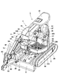
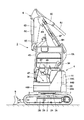
図1、図2において、超小旋回型の小型油圧ショベル1は、例えば市街地における道路脇の側溝掘り作業などの狭い場所での掘削作業に用いられ、一般的なトラックによって搬送できるように、例えば機械重量が0.8〜4トン程度に設定されている。この小型油圧ショベル1は、トラックフレーム2Aの左,右両側にクローラ式の走行装置2Bを備えた自走可能な下部走行体2と、下部走行体2上に旋回装置3を介して旋回可能に支持された上部旋回体4と、下部走行体2の前側に設けられた排土板5と、上部旋回体4の前側に俯仰動可能に設けられたオフセットフロント装置6と、上部旋回体4の後側に位置してオフセットフロント装置6との重量バランスをとるためのカウンタウエイト28とを含んで構成されている。   1 and 2, an ultra-small swivel type small hydraulic excavator 1 is used for excavation work in a narrow place such as a side ditch work on a roadside in an urban area, for example, so that it can be conveyed by a general truck, for example, The machine weight is set to about 0.8 to 4 tons. The small excavator 1 is capable of self-propelled lower traveling body 2 having crawler traveling devices 2B on both the left and right sides of the track frame 2A, and can be turned on the lower traveling body 2 via a turning device 3. The supported upper revolving unit 4, the earth removing plate 5 provided on the front side of the lower traveling unit 2, the offset front device 6 provided on the front side of the upper revolving unit 4 so as to be able to move up and down, and the upper revolving unit 4 A counterweight 28 for balancing the weight with the offset front device 6 is provided on the rear side.

旋回装置3は、下部走行体2と上部旋回体4との間に設けられた旋回輪7と、上部旋回体4を旋回駆動する旋回モータ8(図4参照)とにより構成されている。図2に示すように、旋回輪7は、後述する旋回フレーム9のセンタフレーム10に取付けられる外輪7Aと、外輪7A内に外輪7Aと同軸に配置され複数個の鋼球(いずれも図示せず)を介して回転自在に接続され、下部走行体2のトラックフレーム2A上に取付けられた内筒7Bとにより構成されている。内筒7Bの内周側には、内歯(図示せず)が形成され、この内歯には、後述する旋回モータ8のピニオン8Bが噛合している。   The turning device 3 includes a turning wheel 7 provided between the lower traveling body 2 and the upper turning body 4, and a turning motor 8 (see FIG. 4) that drives the upper turning body 4 to turn. As shown in FIG. 2, the turning wheel 7 includes an outer ring 7A attached to a center frame 10 of a turning frame 9 described later, and a plurality of steel balls (not shown) arranged coaxially with the outer ring 7A in the outer ring 7A. ), And an inner cylinder 7B mounted on the track frame 2A of the lower traveling body 2. Inner teeth (not shown) are formed on the inner peripheral side of the inner cylinder 7B, and a pinion 8B of a turning motor 8 described later meshes with the inner teeth.

また、外輪7Aには、軸方向に貫通するボルト挿通孔(図示せず)が周方向に列設されている。外輪7Aは、各ボルト挿通孔に挿通されたボルト(図示せず)をセンタフレーム10の旋回輪取付孔群17に螺着することにより、センタフレーム10に取付けられている。   Further, bolt insertion holes (not shown) penetrating in the axial direction are arranged in the outer ring 7A in the circumferential direction. The outer ring 7 </ b> A is attached to the center frame 10 by screwing bolts (not shown) inserted through the respective bolt insertion holes into the swivel ring attachment hole group 17 of the center frame 10.

一方、旋回モータ8は、後述するセンタフレーム10上に固着された旋回モータ取付座19に取付けられている。具体的には、図10に示すように、旋回モータ8は、上,下方向に延びる段付筒状のモータケース8Aと、モータケース8Aに設けられた油圧モータ、減速装置、出力軸(いずれも図示せず)と、出力軸に設けられたピニオン8Bとを含んで構成されている。   On the other hand, the turning motor 8 is attached to a turning motor mounting seat 19 fixed on a center frame 10 described later. Specifically, as shown in FIG. 10, the turning motor 8 includes a stepped cylindrical motor case 8 </ b> A extending in the upward and downward directions, a hydraulic motor, a speed reducer, and an output shaft (whichever is provided) (Not shown) and a pinion 8B provided on the output shaft.

旋回モータ8は、モータケース8Aの下部に水平方向に延びて設けられた複数のブラケット8A1が旋回モータ取付座19上に載置される。この状態で、複数本のボルト8Cを各ブラケット8A1に挿通し、各ボルト8Cを旋回モータ取付座19のねじ孔19Bに螺着する。これにより、旋回モータ8は、旋回モータ取付座19(センタフレーム10)上に取付けられている。   In the swing motor 8, a plurality of brackets 8 </ b> A <b> 1 that extend horizontally in the lower portion of the motor case 8 </ b> A are placed on the swing motor mounting seat 19. In this state, a plurality of bolts 8C are inserted into the brackets 8A1, and the bolts 8C are screwed into the screw holes 19B of the turning motor mounting seat 19. Thus, the turning motor 8 is mounted on the turning motor mounting seat 19 (center frame 10).

オフセットフロント装置6は、後述する旋回フレーム9の左,右の前縦板11,12にブームフート部6A1が俯仰動可能に取付けられたロアブーム6Aと、ロアブーム6Aの先端側に左,右方向に揺動可能に取付けられたアッパブーム6Bと、アッパブーム6Bの先端側に左,右方向に揺動可能に取付けられたアーム支持体6Cと、アーム支持体6Cの先端側に上,下方向に回動可能に取付けられたアーム6Dと、アーム6Dの先端側に上,下方向に回動可能に取付けられたバケット6Eと、ロアブーム6Aとアーム支持体6Cとの間を連結するリンク6Fと、これらを動作させるためのブームシリンダ6G、オフセットシリンダ6H、アームシリンダ6J、バケットシリンダ6Kとにより構成されている。   The offset front device 6 includes a lower boom 6A in which a boom foot portion 6A1 is attached to left and right front vertical plates 11 and 12 of a revolving frame 9, which will be described later, and a left and right swing at the tip side of the lower boom 6A. An upper boom 6B that is movably mounted, an arm support 6C that is swingably mounted left and right on the distal end side of the upper boom 6B, and an upward and downward pivotable movement on the distal end side of the arm support 6C An arm 6D attached to the arm 6D, a bucket 6E rotatably attached to the tip end side of the arm 6D, a link 6F connecting the lower boom 6A and the arm support 6C, and the operation thereof The boom cylinder 6G, the offset cylinder 6H, the arm cylinder 6J, and the bucket cylinder 6K are configured.

一方、図3、図4に示すように、ロアブーム6Aのブームフート部6A1は、左,右の前縦板11,12の前側に位置するブラケット11A,12Aに連結ピン(図示せず)を介して回動可能に結合されている。さらに、各シリンダ6G〜6Kは、それぞれ後述の制御弁群26に各油圧ホース43を介して接続されている。   On the other hand, as shown in FIGS. 3 and 4, the boom foot portion 6A1 of the lower boom 6A is connected to brackets 11A and 12A located on the front side of the left and right front vertical plates 11 and 12 via connecting pins (not shown). It is pivotally connected. Further, each of the cylinders 6G to 6K is connected to a later-described control valve group 26 via each hydraulic hose 43.

オフセットフロント装置6は、オフセットシリンダ6Hが伸長、縮小することにより、アーム6Dをロアブーム6Aに対して左,右方向に平行移動させる。この状態でロアブーム6Aを俯仰動させつつアーム6D、バケット6Eを回動させることにより、側溝等の掘削作業を行うことができる。   The offset front device 6 translates the arm 6D in the left and right directions with respect to the lower boom 6A as the offset cylinder 6H expands and contracts. In this state, excavation work such as a gutter can be performed by rotating the arm 6D and the bucket 6E while raising and lowering the lower boom 6A.

ここで、図2に示すように、オフセットフロント装置6は、ロアブーム6Aの先端側を最も後方まで仰動させ、かつアーム6Dをロアブーム6A側に折り畳むことにより、超小旋回姿勢をとることができる。オフセットフロント装置6を超小旋回姿勢とした状態(上方に立上げた状態)では、上部旋回体4を旋回させたときに、上部旋回体4とオフセットフロント装置6とが、下部走行体2の左,右方向の幅寸法(車幅寸法)と前,後方向の長さ寸法内で全旋回することができる構成となっている。この場合、図3に示すように、下部走行体2の車幅寸法は、左,右の走行装置2B間の幅寸法Lによって設定されている。   Here, as shown in FIG. 2, the offset front device 6 can take an ultra-small turning posture by raising the tip side of the lower boom 6 </ b> A to the farthest rear and folding the arm 6 </ b> D to the lower boom 6 </ b> A side. . In a state where the offset front device 6 is in a very small turning posture (upwardly raised), when the upper turning body 4 is turned, the upper turning body 4 and the offset front device 6 are connected to the lower traveling body 2. It is configured to be able to make full turns within the left and right width dimensions (vehicle width dimensions) and the front and rear length dimensions. In this case, as shown in FIG. 3, the vehicle width dimension of the lower traveling body 2 is set by the width dimension L between the left and right traveling apparatuses 2B.

上部旋回体4は、後述する旋回フレーム9、カウンタウエイト28、エンジン29、油圧ポンプ30、熱交換器31、運転席台座32、足置き部材33を含んで構成されている。   The upper swing body 4 includes a swing frame 9, a counterweight 28, an engine 29, a hydraulic pump 30, a heat exchanger 31, a driver seat base 32, and a footrest member 33 which will be described later.

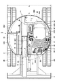
ここで、図3に示すように、上部旋回体4は、下部走行体2の車幅寸法(左,右の走行装置2B間の幅寸法L)とほぼ等しい左,右方向の幅寸法を有している。一方、カウンタウエイト28の外周面28Aは、上部旋回体4の旋回中心Oを中心とした旋回半径Rの仮想円C1内に収まるように、上方から見てほぼ円形状に形成されている。これにより、小型油圧ショベル1は、オフセットフロント装置6を上方に立上げた超小旋回姿勢の状態で、上部旋回体4が下部走行体2上で旋回中心Oを中心として旋回したときに、上部旋回体4がオフセットフロント装置6と共にほぼ下部走行体2の左,右方向の幅寸法(車幅寸法)と前,後方向の長さ寸法内に収まる超小旋回型の油圧ショベルとして構成されている。   Here, as shown in FIG. 3, the upper-part turning body 4 has a width dimension in the left and right directions substantially equal to the vehicle width dimension of the lower traveling body 2 (the width dimension L between the left and right traveling devices 2B). doing. On the other hand, the outer peripheral surface 28A of the counterweight 28 is formed in a substantially circular shape when viewed from above so as to be within a virtual circle C1 having a turning radius R around the turning center O of the upper turning body 4. As a result, the small excavator 1 is in a state where the upper turning body 4 turns around the turning center O on the lower traveling body 2 in the ultra-small turning posture with the offset front device 6 raised upward. The swing body 4 is configured as an ultra-small swing type hydraulic excavator that fits within the left and right width dimensions (vehicle width dimension) and the front and rear length dimensions of the lower traveling body 2 together with the offset front device 6. Yes.

次に、上部旋回体4の支持構造体をなす旋回フレーム9の構成について、図4〜図10を参照しつつ説明する。   Next, the structure of the turning frame 9 that forms the support structure of the upper turning body 4 will be described with reference to FIGS.

旋回フレーム9は、上部旋回体4のベースとなるもので、強固な支持構造体を形成している。図7、図9等に示すように、旋回フレーム9は、旋回装置3を構成する旋回輪7の外輪7Aが取付けられる平板状のセンタフレーム10と、センタフレーム10の前,後方向の中間部から前側に位置してセンタフレーム10上に左,右方向に一定の間隔を保った状態で前,後方向に延びて立設された左前縦板11、右前縦板12と、センタフレーム10の前,後方向の中間部に位置する右前縦板12の後端から左,右方向の左側に延びて立設された中間横板13と、センタフレーム10の左端近傍に位置して中間横板13から後方に延びて立設された左後縦板14と、右前縦板12の後側に連続するように中間横板13から後方に延びて立設された右後縦板15と、左,右の後縦板14,15の後端に亘って左,右方向に延びて立設された後横板16と、後述する制御弁ユニット24とを含んで構成されている。   The revolving frame 9 is a base of the upper revolving structure 4 and forms a strong support structure. As shown in FIGS. 7, 9, etc., the turning frame 9 includes a flat center frame 10 to which the outer ring 7 </ b> A of the turning wheel 7 constituting the turning device 3 is attached, and an intermediate portion in the front and rear directions of the center frame 10. The left front vertical plate 11, the right front vertical plate 12, and the center frame 10, which are erected from the front side and extending in the front and rear directions with a certain distance left and right on the center frame 10. An intermediate horizontal plate 13 erected from the rear end of the right front vertical plate 12 positioned at the front and rear intermediate portions to the left and left of the right direction, and an intermediate horizontal plate positioned near the left end of the center frame 10 A left rear vertical plate 14 extending rearward from 13, a right rear vertical plate 15 extending rearward from the intermediate horizontal plate 13 so as to continue to the rear side of the right front vertical plate 12, , After being erected to extend left and right over the rear ends of the right rear vertical plates 14 and 15 A plate 16 is configured to include a control valve unit 24 described later.

センタフレーム10は、例えば厚肉な鋼板からなり、前,後方向に長尺な長方形状に形成されている。また、図7に示すように、センタフレーム10には、上部旋回体4の旋回中心Oを中心として旋回輪取付孔群17が円形状に列設されている。この旋回輪取付孔群17は、旋回装置3を構成する旋回輪7の外輪7Aを取付けるための複数個のねじ孔17Aからなり、各ねじ孔17Aは、旋回中心Oを中心とする仮想円C2上に配置されている。この場合、大きな旋回輪7によって上部旋回体4を安定的に支持できるように、旋回輪取付孔群17は、センタフレーム10の全幅に近い位置まで大きく形成されている。   The center frame 10 is made of, for example, a thick steel plate, and is formed in a rectangular shape that is long in the front and rear directions. In addition, as shown in FIG. 7, the center frame 10 has a swivel wheel mounting hole group 17 arranged in a circular shape around the turning center O of the upper turning body 4. The swivel wheel mounting hole group 17 includes a plurality of screw holes 17A for mounting the outer ring 7A of the swivel wheel 7 constituting the swivel device 3, and each screw hole 17A has a virtual circle C2 centered on the swivel center O. Is placed on top. In this case, the swivel wheel mounting hole group 17 is formed large to a position close to the full width of the center frame 10 so that the upper swivel body 4 can be stably supported by the large swirl wheel 7.

この上で、センタフレーム10は、旋回輪取付孔群17よりも左側で、中間横板13よりも前側が切欠かれており、この切欠端縁10Aには、後述の傾斜フレーム23が設けられている。また、センタフレーム10の前端縁10Bは、各前縦板11,12の前部よりも旋回輪取付孔群17側に後退した位置に配置されている。この前端縁10Bには、後述の右前フレーム20、左前フレーム21が設けられている。さらに、切欠端縁10Aから左側部分は、センタフレーム10の左側部分を省略することにより、空間状の切欠部位10Cとなっている。この切欠部位10Cによって旋回フレーム9の軽量化が図られている。   In addition, the center frame 10 is notched on the left side of the swivel wheel mounting hole group 17 and on the front side of the intermediate horizontal plate 13, and an inclined frame 23 described later is provided on the notched edge 10 </ b> A. Yes. Further, the front end edge 10 </ b> B of the center frame 10 is disposed at a position retracted toward the swivel wheel mounting hole group 17 side from the front portions of the front vertical plates 11 and 12. The front end edge 10B is provided with a right front frame 20 and a left front frame 21, which will be described later. Further, the left portion from the notch edge 10 </ b> A is a space-like notch portion 10 </ b> C by omitting the left portion of the center frame 10. The cutout portion 10C reduces the weight of the turning frame 9.

図10に示すように、センタフレーム10には、旋回装置3を構成する旋回モータ8のピニオン8Bを挿通するための旋回モータ挿通孔18が設けられている。この旋回モータ挿通孔18は、旋回輪取付孔群17による仮想円C2の内側で、左前縦板11から左側に離間し、かつ旋回中心Oよりも前側に穿設された円形孔として形成されている。旋回モータ挿通孔18は、旋回モータ8のピニオン8Bが挿通されるものであるから、旋回輪7(仮想円C2)の近傍に配置されている。   As shown in FIG. 10, the center frame 10 is provided with a turning motor insertion hole 18 for inserting the pinion 8 </ b> B of the turning motor 8 constituting the turning device 3. The turning motor insertion hole 18 is formed as a circular hole that is spaced from the left front vertical plate 11 to the left and inside the imaginary circle C2 by the turning wheel mounting hole group 17 and is formed in front of the turning center O. Yes. The turning motor insertion hole 18 is disposed in the vicinity of the turning wheel 7 (virtual circle C2) because the pinion 8B of the turning motor 8 is inserted therethrough.

左,右の前縦板11,12は、上部旋回体4の旋回中心Oよりも左,右方向の右側に片寄った位置に配置されている。左,右の前縦板11,12のうち旋回中心Oよりも前側となる部位は、センタフレーム10から上方に突出した山形のブラケット11A,12Aとなっている。これらブラケット11A,12Aには、ロアブーム6Aのブームフート部6A1が俯仰動可能に取付けられる。ここで、左前縦板11は、後述する居住領域47の右側の端縁を構成している。   The left and right front vertical plates 11 and 12 are arranged at positions shifted to the right in the left and right directions with respect to the turning center O of the upper turning body 4. Of the left and right front vertical plates 11, 12, the front part of the turning center O is angled brackets 11 A, 12 A protruding upward from the center frame 10. The boom foot 6A1 of the lower boom 6A is attached to the brackets 11A and 12A so as to be able to move up and down. Here, the left front vertical plate 11 constitutes the right edge of the living area 47 described later.

中間横板13は、旋回中心Oよりも後側に位置して左前縦板11よりも左側に延び、センタフレーム10の切欠端縁10Aから左方向に突出している。中間横板13は、後述するエンジン29と制御弁ユニット24との間を仕切ると共に、後述する運転席台座32の前側を支持するものである。   The intermediate horizontal plate 13 is located rearward of the turning center O, extends to the left of the left front vertical plate 11, and protrudes leftward from the cutout edge 10 </ b> A of the center frame 10. The intermediate horizontal plate 13 partitions an engine 29 and a control valve unit 24, which will be described later, and supports the front side of a driver seat base 32, which will be described later.

次に、旋回フレーム9の一部を構成すると共に、本実施の形態の特徴部分に関連する旋回モータ取付座19について述べる。   Next, a swing motor mounting seat 19 that constitutes a part of the swing frame 9 and is related to the characteristic portion of the present embodiment will be described.

旋回モータ取付座19は、旋回モータ8が取付けられるもので、旋回モータ挿通孔18を取囲んでセンタフレーム10上に固着されている。図10に示すように、旋回モータ取付座19は、略長方形状(略六角形状)の厚板の中央に、旋回モータ挿通孔18と連通する旋回モータ取付孔19Aを有している。ここで、旋回モータ取付座19は、旋回輪取付孔群17の各ねじ孔17Aの中心軸を通る仮想円C2の接線方向が長尺となるように配置されている。これにより、旋回モータ取付座19は、旋回輪取付孔群17が列設された周方向、即ち、センタフレーム10に対して旋回輪7の外輪7Aが取付けられる方向で、この取付部分を旋回モータ取付座19によって長い距離で補強することができる。   The swing motor mounting seat 19 is for mounting the swing motor 8 and is fixed on the center frame 10 so as to surround the swing motor insertion hole 18. As shown in FIG. 10, the swing motor mounting seat 19 has a swing motor mounting hole 19 </ b> A communicating with the swing motor insertion hole 18 in the center of a substantially rectangular (substantially hexagonal) thick plate. Here, the turning motor mounting seat 19 is arranged so that the tangential direction of the virtual circle C2 passing through the central axis of each screw hole 17A of the turning wheel mounting hole group 17 is long. As a result, the turning motor mounting seat 19 moves the mounting portion in the circumferential direction in which the turning wheel mounting hole group 17 is arranged, that is, the direction in which the outer ring 7A of the turning wheel 7 is attached to the center frame 10. The mounting seat 19 can be reinforced at a long distance.

また、旋回モータ取付座19には、旋回モータ取付孔19Aの周囲、具体的には、角部の4箇所にねじ孔19Bが形成されている。図8に示すように、旋回モータ取付座19は、例えば、全周がセンタフレーム10の上面に溶接手段を用いて固着されている。そして、旋回モータ取付座19には、旋回モータ取付孔19Aにピニオン8Bが挿通されつつ、モータケース8Aの各ブラケット8A1が載置される。この状態で、各ブラケット8A1に挿通したボルト8Cを、旋回モータ取付座19のねじ孔19Bに螺着する。これにより、旋回モータ取付座19上に旋回モータ8を取付けることができる。   The turning motor mounting seat 19 is formed with screw holes 19B around the turning motor mounting hole 19A, specifically, at four corners. As shown in FIG. 8, for example, the entire circumference of the turning motor mounting seat 19 is fixed to the upper surface of the center frame 10 using welding means. The bracket 8A1 of the motor case 8A is placed on the swing motor mounting seat 19 while the pinion 8B is inserted through the swing motor mounting hole 19A. In this state, the bolt 8C inserted through each bracket 8A1 is screwed into the screw hole 19B of the turning motor mounting seat 19. Thereby, the turning motor 8 can be mounted on the turning motor mounting seat 19.

次に、本実施の形態の特徴部分となる旋回フレーム9の右前フレーム20、左前フレーム21、左後フレーム22、傾斜フレーム23の構成について述べる。   Next, the configuration of the right front frame 20, the left front frame 21, the left rear frame 22, and the inclined frame 23 of the turning frame 9, which is a characteristic part of the present embodiment, will be described.

旋回フレーム9には、左前縦板11の左側に位置して左前縦板11に沿うようにセンタフレーム10の前端縁10Bから前側に延びた右前フレーム20と、右前フレーム20から左側に離間しセンタフレーム10の左部位から前側に延びた左前フレーム21と、中間横板13に沿うようにセンタフレーム10から切欠端縁10Aから左側に延びた左後フレーム22と、後述の傾斜フレーム23が設けられている。   The revolving frame 9 includes a right front frame 20 that is located on the left side of the left front vertical plate 11 and extends from the front edge 10B of the center frame 10 to the front side along the left front vertical plate 11, and is spaced apart from the right front frame 20 to the left side and centered. A left front frame 21 extending from the left portion of the frame 10 to the front side, a left rear frame 22 extending from the center frame 10 to the left side from the notched edge 10A along the intermediate horizontal plate 13, and an inclined frame 23 described later are provided. ing.

図8に示すように、左,右の前フレーム20,21は、断面C字状の鋼材からなり、その上面側には、後述する制御弁ユニット24の取付台25の前側部分を取付けるためのボルト27が挿通されるボルト挿通孔20A,21Aが、例えば前,後方向に離間して2個形成されている。一方、左後フレーム22には、取付台25の後側部分を取付けるためのボルト27が螺着されるねじ孔22Aが、例えば左,右方向に離間して2個形成されている。   As shown in FIG. 8, the left and right front frames 20 and 21 are made of steel material having a C-shaped cross section, and a front portion of a mounting base 25 of a control valve unit 24 described later is attached to the upper surface side thereof. Two bolt insertion holes 20A and 21A through which the bolts 27 are inserted are formed, for example, spaced apart in the front and rear directions. On the other hand, the left rear frame 22 is formed with two screw holes 22A into which bolts 27 for attaching the rear portion of the mounting base 25 are screwed apart, for example, in the left and right directions.

傾斜フレーム23は、センタフレーム10の左前部分に設けられている。傾斜フレーム23は、センタフレーム10の左前部分から左斜め前側に延びて設けられている。即ち、傾斜フレーム23は、基端側がセンタフレーム10の切欠端縁10Aの前部位置に取付けられ、先端側が自由端となって径方向の外側に向けて延びている。   The inclined frame 23 is provided at the left front portion of the center frame 10. The inclined frame 23 extends from the left front portion of the center frame 10 to the left front side. In other words, the inclined frame 23 is attached to the front position of the cutout edge 10A of the center frame 10 on the base end side, and extends toward the outside in the radial direction with the front end side being a free end.

傾斜フレーム23は、長尺な台形状の上面板部23Aと、この上面板部23Aの長辺から立下った一対の立下り板部23Bとにより、断面C字状の強度部材として形成されている。上面板部23Aには、取付台25の左前側部分を取付けるためのボルト27が挿通されるボルト挿通孔23Cが、例えば左,右方向に離間して2個形成されている。   The inclined frame 23 is formed as a strength member having a C-shaped cross section by a long trapezoidal upper surface plate portion 23A and a pair of falling plate portions 23B falling from the long side of the upper surface plate portion 23A. Yes. In the upper surface plate portion 23A, two bolt insertion holes 23C through which the bolts 27 for attaching the left front side portion of the mounting base 25 are inserted are formed, for example, separated in the left and right directions.

ここで、図7に示すように、傾斜フレーム23は、上部旋回体4の旋回中心O、旋回装置3の旋回モータ8および後述する制御弁ユニット24の重心位置Gを通る斜めの直線B−Bに沿うように延びている。   Here, as shown in FIG. 7, the inclined frame 23 is an oblique straight line BB passing through the turning center O of the upper turning body 4, the turning motor 8 of the turning device 3, and the gravity center position G of the control valve unit 24 described later. It extends so that.

これにより、傾斜フレーム23は、センタフレーム10の左側を大きく切欠いた状態でも、制御弁ユニット24の取付台25を支持するための支持面積を確保している。また、傾斜フレーム23は、制御弁ユニット24の重心位置Gを通る斜めの直線B−Bに沿って形成されているから、制御弁ユニット24をバランスよく安定的に支持している。   Thus, the inclined frame 23 secures a support area for supporting the mounting base 25 of the control valve unit 24 even when the left side of the center frame 10 is greatly cut away. Further, since the inclined frame 23 is formed along an oblique straight line BB passing through the gravity center position G of the control valve unit 24, the inclined frame 23 supports the control valve unit 24 stably in a balanced manner.

さらに、傾斜フレーム23の基端側が取付けられているセンタフレーム10の左前側部位には、近傍に位置して旋回モータ取付座19が取付けられている。これにより、傾斜フレーム23の取付強度を担うセンタフレーム10の左前側部位の剛性を高めることができる。しかも、旋回モータ取付座19は、旋回輪取付孔群17による仮想円C2の接線方向が長尺となるように配置しているから、旋回モータ取付座19の長辺側でセンタフレーム10を効果的に補強することができる。この結果、傾斜フレーム23の強度がより一層高まる。   Further, a turning motor mounting seat 19 is mounted in the vicinity of the left front side portion of the center frame 10 to which the base end side of the inclined frame 23 is mounted. Thereby, the rigidity of the left front side part of the center frame 10 that bears the mounting strength of the inclined frame 23 can be increased. Moreover, since the turning motor mounting seat 19 is arranged so that the tangential direction of the virtual circle C2 by the turning wheel mounting hole group 17 is long, the center frame 10 is effective on the long side of the turning motor mounting seat 19. Can be reinforced. As a result, the strength of the inclined frame 23 is further increased.

次に、各フレーム20〜23の上側に設けられる制御弁ユニット24の構成について述べる。   Next, the configuration of the control valve unit 24 provided on the upper side of each of the frames 20 to 23 will be described.

制御弁ユニット24は、旋回フレーム9の左前縦板11よりも左側で、中間横板13よりも前側に配置されている。制御弁ユニット24は、センタフレーム10と切欠部位10Cの上側に位置する取付台25と、この取付台25上に搭載される制御弁群26とにより構成されている。また、制御弁ユニット24に後述の走行操作レバー37、操作ペダル38,39等を組付けることにより、図5に示すサブ組立体を組立てることができる。制御弁ユニット24は、後述するオペレータの居住領域47の下方位置に配置されている。   The control valve unit 24 is disposed on the left side of the left front vertical plate 11 of the revolving frame 9 and on the front side of the intermediate horizontal plate 13. The control valve unit 24 includes a mounting base 25 positioned above the center frame 10 and the cutout portion 10 </ b> C, and a control valve group 26 mounted on the mounting base 25. Further, the sub-assembly shown in FIG. 5 can be assembled by assembling a travel operation lever 37, operation pedals 38, 39 and the like, which will be described later, to the control valve unit 24. The control valve unit 24 is disposed at a position below an operator's living area 47 described later.

図8に示すように、取付台25は、左端側が上部旋回体4の仮想円C1に沿って円弧状に湾曲した略扇状の平板からなる下板25Aと、下板25Aの前側位置に立設された縦板からなる支柱25Bと、支柱25Bの上部に左,右方向に延びて設けられたレバー・ペダル取付板25Cとを含んで構成されている。ここで、レバー・ペダル取付板25Cは、居住領域47の最前部分を構成している。   As shown in FIG. 8, the mounting base 25 is erected at a front side of the lower plate 25 </ b> A composed of a substantially fan-shaped flat plate whose left end is curved in an arc along the virtual circle C <b> 1 of the upper swing body 4. The support column 25B is formed of a vertical plate, and the lever / pedal mounting plate 25C is provided on the upper side of the support column 25B so as to extend leftward and rightward. Here, the lever / pedal mounting plate 25 </ b> C constitutes the foremost part of the living area 47.

下板25Aの右前側には、右前フレーム20の各ボルト挿通孔20Aに対応する位置にねじ孔25A1(溶接ナット)が設けられている。下板25Aの中央前側には、左前フレーム21の各ボルト挿通孔21Aに対応する位置にねじ孔25A2が設けられている。下板25Aの左後側には、左後フレーム22の各ねじ孔22Aに対応する位置にボルト挿通孔25A3が設けられている。さらに、下板25Aの前,後方向の中間部の左寄り位置には、傾斜フレーム23の各ボルト挿通孔23Cに対応する位置にねじ孔25A4が設けられている。   On the right front side of the lower plate 25A, screw holes 25A1 (welding nuts) are provided at positions corresponding to the respective bolt insertion holes 20A of the right front frame 20. On the center front side of the lower plate 25A, screw holes 25A2 are provided at positions corresponding to the bolt insertion holes 21A of the left front frame 21. Bolt insertion holes 25A3 are provided at positions corresponding to the respective screw holes 22A of the left rear frame 22 on the left rear side of the lower plate 25A. Furthermore, screw holes 25A4 are provided at positions corresponding to the respective bolt insertion holes 23C of the inclined frame 23, at positions to the left of the front and rear intermediate portions of the lower plate 25A.

制御弁群26は、取付台25の下板25A上に搭載されている。制御弁群26は、レバー・ペダル取付板25Cの後側近傍に位置し、複数個の制御弁を左,右方向に連ねることにより構成されている。制御弁群26は、オフセットフロント装置6の各シリンダ6G〜6K、下部走行体2の走行モータ、旋回装置3の旋回モータ8および油圧ポンプ30に後述の油圧ホース43を介して接続されている。   The control valve group 26 is mounted on the lower plate 25 </ b> A of the mounting base 25. The control valve group 26 is located in the vicinity of the rear side of the lever / pedal mounting plate 25C, and is configured by connecting a plurality of control valves in the left and right directions. The control valve group 26 is connected to the cylinders 6G to 6K of the offset front device 6, the travel motor of the lower traveling body 2, the swing motor 8 of the swing device 3, and the hydraulic pump 30 via a hydraulic hose 43 described later.

このように構成された制御弁ユニット24は、取付台25の下板25A上に制御弁群26を搭載する。図7に示すように、このときに、制御弁ユニット24の重心位置Gは、制御弁群26の上部のほぼ中央に位置している。そこで、重心位置Gが傾斜フレーム23上に位置するように、制御弁ユニット24を、右前フレーム20、左前フレーム21、左後フレーム22、傾斜フレーム23上に載置する。   The control valve unit 24 configured in this manner mounts the control valve group 26 on the lower plate 25 </ b> A of the mounting base 25. As shown in FIG. 7, at this time, the center-of-gravity position G of the control valve unit 24 is located substantially at the center of the upper part of the control valve group 26. Therefore, the control valve unit 24 is placed on the right front frame 20, the left front frame 21, the left rear frame 22, and the tilt frame 23 so that the gravity center position G is located on the tilt frame 23.

図8に示すように、右前フレーム20の各ボルト挿通孔20Aに下側から挿通したボルト27を、下板25Aのねじ孔25A1に螺着する。また、左前フレーム21の各ボルト挿通孔21Aに下側から挿通したボルト27を、下板25Aのねじ孔25A2に螺着する。一方、下板25Aの各ボルト挿通孔25A3に上側から挿通したボルト27を、左後フレーム22の各ねじ孔22Aに螺着する。さらに、傾斜フレーム23の各ボルト挿通孔23Cに下側から挿通したボルト27を、下板25Aのねじ孔25A4に螺着する。従って、右前フレーム20、左前フレーム21および左後フレーム22は、傾斜フレーム23と一緒に制御弁ユニット24の取付台25を支持している。   As shown in FIG. 8, bolts 27 inserted from below into the bolt insertion holes 20A of the right front frame 20 are screwed into the screw holes 25A1 of the lower plate 25A. Further, the bolts 27 inserted from the lower side into the respective bolt insertion holes 21A of the left front frame 21 are screwed into the screw holes 25A2 of the lower plate 25A. On the other hand, the bolts 27 inserted from above into the respective bolt insertion holes 25A3 of the lower plate 25A are screwed into the respective screw holes 22A of the left rear frame 22. Further, the bolts 27 inserted from below into the respective bolt insertion holes 23C of the inclined frame 23 are screwed into the screw holes 25A4 of the lower plate 25A. Therefore, the right front frame 20, the left front frame 21, and the left rear frame 22 support the mounting base 25 of the control valve unit 24 together with the inclined frame 23.

これにより、制御弁ユニット24は旋回フレーム9の左前側位置に一体的に取付けることができる。このときに、制御弁ユニット24の取付台25は、左前側部位が傾斜フレーム23に支持されている。   Thus, the control valve unit 24 can be integrally attached to the left front position of the turning frame 9. At this time, a left front portion of the mounting base 25 of the control valve unit 24 is supported by the inclined frame 23.

次に、小型油圧ショベル1に設けられたカウンタウエイト28、エンジン29、運転席台座32、足置き部材33等の部材について述べる。   Next, members such as the counterweight 28, the engine 29, the driver seat base 32, and the footrest member 33 provided in the small hydraulic excavator 1 will be described.

図2、図3等に示すように、カウンタウエイト28は、オフセットフロント装置6との重量バランスをとるために旋回フレーム9の後側に取付けられている。カウンタウエイト28は、左,右方向の中央が後方に突出する円弧状の重量物として形成されている。これにより、カウンタウエイト28の外周面28Aは、前述した旋回半径Rの仮想円C1内にほぼ収まる円弧面として形成されている。   As shown in FIGS. 2, 3, etc., the counterweight 28 is attached to the rear side of the turning frame 9 in order to balance the weight with the offset front device 6. The counterweight 28 is formed as an arcuate heavy object whose center in the left and right directions protrudes backward. As a result, the outer peripheral surface 28A of the counterweight 28 is formed as an arc surface that is substantially contained within the imaginary circle C1 having the turning radius R described above.

エンジン29は、カウンタウエイト28の前側に位置して旋回フレーム9上に搭載されている。エンジン29は、旋回フレーム9の中間横板13と後横板16との間に位置して各後縦板14,15上に左,右方向に延在する横置き状態で搭載されている。エンジン29の左側には、後述する油圧ポンプ30が取付けられている。一方、エンジン29の右側には、冷却ファン(図示せず)が設けられている。   The engine 29 is mounted on the turning frame 9 so as to be positioned on the front side of the counterweight 28. The engine 29 is mounted between the intermediate horizontal plate 13 and the rear horizontal plate 16 of the revolving frame 9 in a horizontally placed state extending left and right on the rear vertical plates 14 and 15. A hydraulic pump 30 described later is attached to the left side of the engine 29. On the other hand, a cooling fan (not shown) is provided on the right side of the engine 29.

油圧ポンプ30は、エンジン29の左側に取付けられ、エンジン29により回転駆動される。この油圧ポンプ30は、後述の作動油タンク42内から油液を吸込みつつ、この油液を高圧な圧油として吐出する。油圧ポンプ30から吐出された圧油は、制御弁群26、各油圧ホース43を介してオフセットフロント装置6の各油圧シリンダ6G〜6K等に供給される。   The hydraulic pump 30 is attached to the left side of the engine 29 and is driven to rotate by the engine 29. The hydraulic pump 30 discharges the oil as high pressure oil while sucking the oil from a hydraulic oil tank 42 described later. The pressure oil discharged from the hydraulic pump 30 is supplied to the hydraulic cylinders 6G to 6K of the offset front device 6 through the control valve group 26 and the hydraulic hoses 43.

熱交換器31は、エンジン29の冷却ファンに対面するように旋回フレーム9上に設けられている。この熱交換器31は、ラジエータ、オイルクーラ等を含んで構成されている。   The heat exchanger 31 is provided on the revolving frame 9 so as to face the cooling fan of the engine 29. The heat exchanger 31 includes a radiator, an oil cooler, and the like.

運転席台座32は、旋回フレーム9を構成する左前縦板11の左側に位置し、エンジン29の上側を覆うように旋回フレーム9上に設けられている。この運転席台座32は、上部旋回体4の旋回中心Oを通る前,後方向の中心線をA−A(図3参照)としたときに、この中心線A−Aを越えて左前縦板11まで達する領域が、後述するオペレータの居住領域47として設定されている。このように、本実施の形態による小型油圧ショベル1では、運転席台座32上を居住領域47の後側部分として利用している。一方、運転席台座32の前側には、制御弁ユニット24、足置き部材33等が配置されている。   The driver seat pedestal 32 is located on the left side of the left front vertical plate 11 constituting the revolving frame 9 and is provided on the revolving frame 9 so as to cover the upper side of the engine 29. This driver's seat pedestal 32 has a left front vertical plate that crosses the center line AA when the rear center line is AA (see FIG. 3) before passing through the turning center O of the upper swing body 4. An area reaching 11 is set as an operator residence area 47 described later. Thus, in the small hydraulic excavator 1 according to the present embodiment, the driver seat base 32 is used as the rear portion of the living area 47. On the other hand, on the front side of the driver seat base 32, a control valve unit 24, a footrest member 33 and the like are arranged.

ここで、図6に示すように、運転席台座32は、旋回フレーム9の中間横板13上に位置して左,右方向に延びて立設された前面部位32Aと、前面部位32Aの上部から後側に延びた運転席取付部位32Bと、運転席取付部位32Bの後部から後側に向けて斜め上側に傾斜した背板部位32Cと、背板部位32Cの上部(後部)から後側に延びたウエイト取付部位32Dとを含んで構成されている。   Here, as shown in FIG. 6, the driver seat base 32 is positioned on the intermediate horizontal plate 13 of the revolving frame 9, and extends in the left and right directions, and the front part 32 </ b> A and the upper part of the front part 32 </ b> A. A driver seat mounting part 32B extending from the rear to the rear, a back plate part 32C inclined obliquely upward from the rear to the rear side of the driver seat mounting part 32B, and an upper part (rear part) of the back plate part 32C from the rear to the rear An extended weight attaching portion 32D is included.

運転席台座32は、前面部位32Aの下部が旋回フレーム9の中間横板13の上部に取付けられ、ウエイト取付部位32Dがカウンタウエイト28の上面に取付けられている。これにより、運転席台座32は、エンジン29、油圧ポンプ30の前側と上側を覆っている。運転席台座32の運転席取付部位32Bには、後述の運転席34、左,右のフロント操作装置35,36等が取付けられている。   The driver seat base 32 has a lower portion of the front surface portion 32A attached to the upper portion of the intermediate horizontal plate 13 of the turning frame 9 and a weight attachment portion 32D attached to the upper surface of the counterweight 28. Accordingly, the driver seat base 32 covers the front side and the upper side of the engine 29 and the hydraulic pump 30. A driver seat 34, which will be described later, left and right front operating devices 35, 36, and the like are attached to the driver seat mounting portion 32 </ b> B of the driver seat base 32.

足置き部材33は、運転席台座32の前側に位置して旋回フレーム9に設けられている。足置き部材33は、左,右方向に延びる長方形の平板によって形成されている。足置き部材33は、前側が取付台25のレバー・ペダル取付板25Cに取付けられ、後側が運転席台座32の前面部位32Aの下部に取付けられている。足置き部材33は、取付台25のレバー・ペダル取付板25Cと運転席台座32との間に配置され、レバー・ペダル取付板25Cと一緒に居住領域47の前側部分を構成している。この足置き部材33の下方には、制御弁ユニット24の制御弁群26が配置されている。   The footrest member 33 is located on the front side of the driver seat base 32 and is provided on the turning frame 9. The footrest member 33 is formed by a rectangular flat plate extending in the left and right directions. The footrest member 33 is attached to the lever / pedal attachment plate 25 </ b> C of the attachment base 25 on the front side and attached to the lower part of the front surface portion 32 </ b> A of the driver seat base 32. The footrest member 33 is disposed between the lever / pedal mounting plate 25C of the mounting base 25 and the driver seat base 32, and constitutes a front portion of the living area 47 together with the lever / pedal mounting plate 25C. A control valve group 26 of the control valve unit 24 is disposed below the footrest member 33.

次に、運転席台座32上に搭載される運転席34、左,右のフロント操作装置35,36の構成について説明する。   Next, the configuration of the driver seat 34 and the left and right front operating devices 35 and 36 mounted on the driver seat base 32 will be described.

図1ないし図3に示すように、運転席34は、運転席台座32の運転席取付部位32Bに取付けられ、オペレータが着席するものである。運転席34の左,右両側には、旋回装置3、オフセットフロント装置6を操作するための左,右のフロント操作装置35,36が設けられている。   As shown in FIGS. 1 to 3, the driver's seat 34 is attached to a driver's seat mounting portion 32 </ b> B of the driver's seat pedestal 32 and is seated by an operator. Left and right front operation devices 35 and 36 for operating the turning device 3 and the offset front device 6 are provided on both the left and right sides of the driver's seat 34.

走行操作レバー37は、運転席34の前方となる取付台25のレバー・ペダル取付板25Cに設けられている。この走行操作レバー37は、前,後方向に傾転操作することにより、下部走行体2の走行を操作するものである。また、レバー・ペダル取付板25Cには、走行操作レバー37の左,右両側に位置して、操作ペダル38,39が配置されている。これら各操作ペダル38,39は、例えばオフセットフロント装置6のオフセット操作、オプションとして取付けられる付属機器の操作等を行うものである。   The travel operation lever 37 is provided on the lever / pedal mounting plate 25 </ b> C of the mounting base 25 in front of the driver seat 34. The traveling operation lever 37 is used to operate the traveling of the lower traveling body 2 by tilting in the forward and backward directions. Further, on the lever / pedal mounting plate 25C, operation pedals 38 and 39 are disposed on both the left and right sides of the travel operation lever 37, respectively. Each of these operation pedals 38 and 39 performs, for example, an offset operation of the offset front device 6 and an operation of an accessory device attached as an option.

図4に示すように、センタジョイント40は、上部旋回体4の旋回中心Oに設けられている。センタジョイント40は、下部走行体2と上部旋回体4との間で圧油を流通させるものである。このセンタジョイント40は、下部走行体2を構成するトラックフレーム2Aの中央位置に取付けられている。   As shown in FIG. 4, the center joint 40 is provided at the turning center O of the upper turning body 4. The center joint 40 circulates pressure oil between the lower traveling body 2 and the upper swing body 4. The center joint 40 is attached to the center position of the track frame 2A constituting the lower traveling body 2.

燃料タンク41は、オフセットフロント装置6のブームフート部6A1の右側に位置して旋回フレーム9に搭載されている。燃料タンク41は、貯油タンクを構成するもので、エンジン29に供給される燃料を貯溜している。   The fuel tank 41 is mounted on the revolving frame 9 so as to be located on the right side of the boom foot portion 6A1 of the offset front device 6. The fuel tank 41 constitutes an oil storage tank and stores fuel supplied to the engine 29.

作動油タンク42は、燃料タンク41と共に貯油タンクを構成するもので、オフセットフロント装置6のブームフート部6A1の右側に位置して旋回フレーム9に搭載されている。作動油タンク42は、オフセットフロント装置6の各シリンダ6G〜6K、下部走行体2の走行モータ、旋回装置3の旋回モータ8等の油圧アクチュエータに供給される作動油を貯溜している。   The hydraulic oil tank 42 constitutes an oil storage tank together with the fuel tank 41, and is mounted on the revolving frame 9 so as to be positioned on the right side of the boom foot portion 6 </ b> A <b> 1 of the offset front device 6. The hydraulic oil tank 42 stores hydraulic oil to be supplied to hydraulic actuators such as the cylinders 6G to 6K of the offset front device 6, the traveling motor of the lower traveling body 2, and the turning motor 8 of the turning device 3.

複数本の油圧ホース43は、オフセットフロント装置6の各油圧シリンダ6G〜6K等と制御弁群26と油圧ポンプ30とセンタジョイント40とを接続するものである。本実施の形態では、圧油を給排するための各種管体を総称して油圧ホースと述べている。即ち、油圧ホースには、可撓性の耐圧ホース、金属管等を含むものである。   The plurality of hydraulic hoses 43 connect the hydraulic cylinders 6G to 6K and the like of the offset front device 6, the control valve group 26, the hydraulic pump 30, and the center joint 40. In the present embodiment, various pipes for supplying and discharging pressure oil are collectively referred to as a hydraulic hose. That is, the hydraulic hose includes a flexible pressure hose, a metal pipe, and the like.

次に、上部旋回体4の周囲を覆うために設けられた外装カバー44の構成について述べる。   Next, the configuration of the exterior cover 44 provided to cover the periphery of the upper swing body 4 will be described.

図1ないし図3に示すように、外装カバー44は、旋回フレーム9を構成する制御弁ユニット24の取付台25の前側から左側を覆う左前カバー部44Aと、左前カバー部44Aとカウンタウエイト28との間を覆う左後カバー部44Bと、燃料タンク41、作動油タンク42等を覆うタンクカバー部44Cと、タンクカバー部44Cの後側に位置して熱交換器31等を覆う熱交換器カバー部44Dと、エンジン29のメンテナンス用にカウンタウエイト28に開閉可能に設けられたエンジンカバー部44Eとを含んで構成されている。   As shown in FIGS. 1 to 3, the exterior cover 44 includes a left front cover portion 44 </ b> A that covers the left side from the front side of the mounting base 25 of the control valve unit 24 constituting the revolving frame 9, a left front cover portion 44 </ b> A, a counterweight 28, and the like. The left rear cover portion 44B covering the space, the tank cover portion 44C covering the fuel tank 41, the hydraulic oil tank 42 and the like, and the heat exchanger cover which is located on the rear side of the tank cover portion 44C and covers the heat exchanger 31 and the like 44D and the engine cover part 44E provided in the counterweight 28 so that opening and closing is possible for engine 29 maintenance.

ここで、左前カバー部44Aによって覆われている制御弁ユニット24の取付台25は、センタフレーム10の上側に重なるように配置されている。この場合、左前カバー部44Aは、その下側部位を取付台25の下板25Aを越えて下側まで延ばすことにより、周囲の左後カバー部44Bと下側の端縁部を揃えることができ、見栄えを良好にできる。しかも、取付台25の下板25Aと下部走行体2の走行装置2B(履帯)との間に形成される隙間を小さくでき、乗降時に足が引っ掛からないようにすることができる。   Here, the mounting base 25 of the control valve unit 24 covered with the left front cover portion 44 </ b> A is disposed so as to overlap the upper side of the center frame 10. In this case, the left front cover portion 44A can be aligned with the peripheral left rear cover portion 44B and the lower edge by extending the lower portion of the left front cover portion 25A beyond the lower plate 25A of the mounting base 25. Can look good. Moreover, the gap formed between the lower plate 25A of the mounting base 25 and the traveling device 2B (crawler belt) of the lower traveling body 2 can be reduced, and the foot can be prevented from being caught when getting on and off.

キャノピ45は、運転席34の上方と右側方を覆うように旋回フレーム9、カウンタウエイト28の上側に設けられている。このキャノピ45は、例えば3柱式のキャノピとして構成されている。また、フロアマット46は、取付台25のレバー・ペダル取付板25Cと足置き部材33の上側を覆うように敷説されている。   The canopy 45 is provided above the turning frame 9 and the counterweight 28 so as to cover the upper side and the right side of the driver's seat 34. The canopy 45 is configured as a three-post canopy, for example. Further, the floor mat 46 is laid so as to cover the lever / pedal mounting plate 25C of the mounting base 25 and the upper side of the footrest member 33.

図2、図6等に示すように、オペレータの居住領域47は、小型油圧ショベル1を操作(運転)するときにオペレータが居住するスペースである。オペレータの居住領域47は、制御弁ユニット24の上側に位置し、カウンタウエイト28との間に設けられている。具体的には、運転席台座32と足置き部材33とによって居住領域47が形成されている。   As shown in FIGS. 2, 6, etc., the operator's living area 47 is a space where the operator lives when operating (driving) the small excavator 1. The operator's living area 47 is located on the upper side of the control valve unit 24 and is provided between the counterweight 28. Specifically, a living area 47 is formed by the driver seat base 32 and the footrest member 33.

ここで、オペレータの居住領域47は、エンジン29の上側を覆う運転席台座32、制御弁ユニット24の取付台25を形成するレバー・ペダル取付板25C、制御弁群26の上側を覆う足置き部材33等の上側空間を使用している。即ち、居住領域47の下方には、取付台25の下板25A、制御弁群26、右前フレーム20、左前フレーム21、左後フレーム22、傾斜フレーム23が配置されている。これにより、上部旋回体4のうちオフセットフロント装置6の左側に形成される限られた領域を最大限に有効利用することができる。従って、居住領域47は、小型油圧ショベル1においても、可能な限り大きく確保することができる。   Here, the operator's living area 47 includes a driver seat base 32 that covers the upper side of the engine 29, a lever / pedal mounting plate 25C that forms the mounting base 25 of the control valve unit 24, and a footrest member that covers the upper side of the control valve group 26. An upper space such as 33 is used. That is, below the living area 47, the lower plate 25A of the mounting base 25, the control valve group 26, the right front frame 20, the left front frame 21, the left rear frame 22, and the inclined frame 23 are arranged. Thereby, the limited area | region formed in the left side of the offset front apparatus 6 among the upper turning bodies 4 can be utilized effectively to the maximum. Accordingly, the living area 47 can be secured as large as possible even in the small excavator 1.

本実施の形態による超小旋回型の小型油圧ショベル1は、上述の如き構成を有するもので、次に、その動作について説明する。   The ultra-small turning type small hydraulic excavator 1 according to the present embodiment has the above-described configuration, and the operation thereof will be described next.

まず、オペレータは、足置き部材33に搭乗し、運転席34に着座する。運転席34に着座したオペレータが、走行操作レバー37を操作することにより、下部走行体2を走行させることができる。一方、オペレータが、左,右のフロント操作装置35,36をレバー操作することにより、上部旋回体4の旋回動作、オフセットフロント装置6による土砂の掘削作業等を行うことができる。   First, the operator gets on the footrest member 33 and sits on the driver's seat 34. An operator seated in the driver's seat 34 can drive the lower traveling body 2 by operating the traveling operation lever 37. On the other hand, when the operator operates the left and right front operation devices 35 and 36 by levers, the turning operation of the upper turning body 4 and the excavation work of earth and sand by the offset front device 6 can be performed.

この場合、超小旋回型の小型油圧ショベル1は、オフセットフロント装置6を図2に示す超小旋回姿勢とすることにより、上部旋回体4とオフセットフロント装置6とを、下部走行体2の左,右方向の幅寸法(車幅寸法)と前,後方向の長さ寸法内で全旋回させることができる。これにより、小型油圧ショベル1は、市街地等の狭い作業現場においても、周囲の障害物に干渉することなく、オフセットフロント装置6を用いて側溝掘り作業等を円滑に行うことができる。   In this case, the ultra-small swivel type hydraulic excavator 1 makes the upper swing body 4 and the offset front apparatus 6 to the left of the lower traveling body 2 by setting the offset front device 6 to the ultra-small swing posture shown in FIG. , It is possible to make a full turn within the width dimension in the right direction (vehicle width dimension) and the length dimension in the front and rear directions. As a result, the small excavator 1 can smoothly perform a side ditching operation or the like using the offset front device 6 without interfering with surrounding obstacles even in a narrow work site such as an urban area.

かくして、本実施の形態によれば、旋回フレーム9のセンタフレーム10は、旋回装置3の旋回輪7を取付けるために円形状に列設された旋回輪取付孔群17よりも左側で中間横板13よりも前側が切欠かれている。また、旋回フレーム9の左前縦板11よりも左側で中間横板13よりも前側には、センタフレーム10と切欠部位10Cの上側に位置する取付台25上に制御弁群26が取付けられている制御弁ユニット24が設けられている。さらに、制御弁ユニット24の上側位置には、カウンタウエイト28との間にオペレータが居住する居住領域47が設けられている。   Thus, according to the present embodiment, the center frame 10 of the swivel frame 9 has an intermediate horizontal plate on the left side of the swivel wheel mounting hole group 17 arranged in a circular shape for mounting the swivel wheel 7 of the swivel device 3. The front side of 13 is notched. A control valve group 26 is mounted on a mounting base 25 positioned above the center frame 10 and the cutout portion 10C on the left side of the revolving frame 9 on the left side of the front left vertical plate 11 and on the front side of the intermediate horizontal plate 13. A control valve unit 24 is provided. Further, a living area 47 where an operator lives is provided between the control valve unit 24 and the counterweight 28.

この上で、上部旋回体4の旋回中心O、旋回モータ8および制御弁ユニット24の重心位置Gを通る斜めの直線B−Bに沿うように切欠部位10Cを左斜め前側に延びると共に基端側がセンタフレーム10に取付けられ先端側が自由端となった傾斜フレーム23が設けられている。従って、制御弁ユニット24の取付台25は、左前側部位を傾斜フレーム23によって支持することができる。   In addition, the notch portion 10C extends obliquely to the front left side along the oblique straight line BB passing through the turning center O of the upper turning body 4, the turning motor 8 and the gravity center position G of the control valve unit 24, and the base end side is An inclined frame 23 attached to the center frame 10 and having a free end at the front end side is provided. Therefore, the mounting base 25 of the control valve unit 24 can support the left front side portion by the inclined frame 23.

これにより、傾斜フレーム23は、センタフレーム10の左側を大きく切欠いた状態でも、制御弁ユニット24の取付台25を支持するために十分な支持面積を確保することができる。また、傾斜フレーム23は、制御弁ユニット24の重心位置Gを通る斜めの直線B−Bに沿って形成されているから、制御弁ユニット24をバランスよく安定的に支持することができる。   Thereby, the inclined frame 23 can secure a sufficient support area for supporting the mounting base 25 of the control valve unit 24 even when the left side of the center frame 10 is greatly cut away. Further, since the inclined frame 23 is formed along an oblique straight line BB passing through the gravity center position G of the control valve unit 24, the control valve unit 24 can be stably supported in a balanced manner.

さらに、傾斜フレーム23の基端側が取付けられているセンタフレーム10の左前側部位には、その近傍に位置して旋回モータ取付座19が取付けられている。これにより、傾斜フレーム23の取付強度を担うセンタフレーム10の左前側部位の剛性を、旋回モータ取付座19によって高めることができる。   Further, a turning motor mounting seat 19 is mounted on the left front side portion of the center frame 10 to which the base end side of the inclined frame 23 is mounted in the vicinity thereof. Accordingly, the rigidity of the left front side portion of the center frame 10 that bears the mounting strength of the inclined frame 23 can be increased by the turning motor mounting seat 19.

この結果、傾斜フレーム23の剛性、この傾斜フレーム23による制御弁ユニット24の支持強度を高めることができる。これにより、旋回フレーム9の強度を高めつつ、旋回フレーム9を軽量化することができる。   As a result, the rigidity of the inclined frame 23 and the support strength of the control valve unit 24 by the inclined frame 23 can be increased. Thereby, the strength of the turning frame 9 can be increased, and the turning frame 9 can be reduced in weight.

また、センタフレーム10の旋回モータ取付座19は、旋回モータ挿通孔18と連通する旋回モータ取付孔19Aを有する長方形状の板体からなっている。旋回モータ取付座19は、旋回輪取付孔群17による仮想円C2の接線方向が長尺となるように配置されている。従って、旋回モータ取付座19は、その長辺側でセンタフレーム10を効果的に補強することができる。   Further, the turning motor mounting seat 19 of the center frame 10 is formed of a rectangular plate having a turning motor mounting hole 19 </ b> A communicating with the turning motor insertion hole 18. The turning motor mounting seat 19 is arranged so that the tangential direction of the virtual circle C2 by the turning wheel mounting hole group 17 is long. Therefore, the turning motor mounting seat 19 can effectively reinforce the center frame 10 on its long side.

旋回フレーム9は、左前縦板11に沿うようにセンタフレーム10から前側に延びた右前フレーム20と、右前フレーム20から左側に離間し傾斜フレーム23の基端部位の近傍から前側に延びた左前フレーム21と、中間横板13に沿うようにセンタフレーム10から左側に延びた左後フレーム22とを備えている。この上で、右前フレーム20、左前フレーム21および左後フレーム22は、傾斜フレーム23と一緒に制御弁ユニット24の取付台25を支持している。これにより、傾斜フレーム23は、センタフレーム10の左側を大きく切欠いた状態でも、各フレーム20〜23によって制御弁ユニット24の取付台25を確実に支持することができる。   The revolving frame 9 includes a right front frame 20 that extends forward from the center frame 10 along the left front vertical plate 11, and a left front frame that is spaced leftward from the right front frame 20 and extends forward from the vicinity of the proximal end portion of the inclined frame 23. 21 and a left rear frame 22 extending leftward from the center frame 10 along the intermediate horizontal plate 13. On this, the right front frame 20, the left front frame 21, and the left rear frame 22 support the mounting base 25 of the control valve unit 24 together with the inclined frame 23. Thereby, the inclined frame 23 can reliably support the mounting base 25 of the control valve unit 24 by the respective frames 20 to 23 even when the left side of the center frame 10 is largely cut away.

さらに、旋回フレーム9の後側には、オフセットフロント装置6との重量バランスをとるためのカウンタウエイト28が設けることができる。カウンタウエイト28の前側には、旋回フレーム9上に位置してエンジン29を設けることができる。また、旋回フレーム9には、上部旋回体4の旋回中心Oを通る前,後方向の中心線A−Aを越えて左前縦板11の近傍位置まで延び中間横板13とカウンタウエイト28との間でエンジン29を覆った状態で運転席台座32を設けることができる。さらに、運転席台座32の前側には、制御弁ユニット24の上側に位置して足置き部材33が設けられている。これにより、運転席台座32と足置き部材33とによってオペレータの居住領域47を形成することができる。   Further, a counterweight 28 for balancing the weight with the offset front device 6 can be provided on the rear side of the turning frame 9. An engine 29 can be provided on the swivel frame 9 on the front side of the counterweight 28. Further, the swivel frame 9 extends between the middle horizontal plate 13 and the counterweight 28 before passing through the swivel center O of the upper swivel body 4 and past the rear center line AA to a position near the left front vertical plate 11. The driver seat base 32 can be provided in a state where the engine 29 is covered. Further, a footrest member 33 is provided on the front side of the driver seat base 32 so as to be located above the control valve unit 24. Thereby, the driver's seat base 32 and the footrest member 33 can form the operator's living area 47.

なお、実施の形態では、運転席34の上方と右側方を覆うキャノピ45が設けられたキャノピ仕様の小型油圧ショベル1を例に挙げて説明した。しかし、本発明はこれに限らず、例えば運転席の上方と周囲を覆うキャブが設けられたキャブ仕様の小型油圧ショベルに適用してもよい。   In the embodiment, the small hydraulic excavator 1 of the canopy specification provided with the canopy 45 that covers the upper side and the right side of the driver's seat 34 has been described as an example. However, the present invention is not limited to this. For example, the present invention may be applied to a small cab-type hydraulic excavator provided with a cab that covers the upper and surroundings of the driver's seat.

1 小型油圧ショベル
2 下部走行体
3 旋回装置
4 上部旋回体
6 オフセットフロント装置
7 旋回輪
8 旋回モータ
9 旋回フレーム
10 センタフレーム
10A 切欠端縁
10C 切欠部位
11 左前縦板
11A、12A ブラケット
12 右前縦板
13 中間横板
17 旋回輪取付孔群
18 旋回モータ挿通孔
19 旋回モータ取付座
19A 旋回モータ取付孔
20 右前フレーム
21 左前フレーム
22 左後フレーム
23 傾斜フレーム
24 制御弁ユニット
25 取付台
25A 下板
26 制御弁群
28 カウンタウエイト
29 エンジン
30 油圧ポンプ
31 熱交換器
32 運転席台座
33 足置き部材
47 居住領域
O 旋回中心
G 制御弁ユニットの重心位置
C2 仮想円(円)
A−A 前,後方向の中心線
B−B 斜めの直線
DESCRIPTION OF SYMBOLS 1 Small hydraulic shovel 2 Lower traveling body 3 Turning apparatus 4 Upper turning body 6 Offset front apparatus 7 Turning wheel 8 Turning motor 9 Turning frame 10 Center frame 10A Notch edge 10C Notch part 11 Left front vertical plate 11A, 12A Bracket 12 Right front vertical plate DESCRIPTION OF SYMBOLS 13 Intermediate horizontal plate 17 Rotating wheel mounting hole group 18 Rotating motor insertion hole 19 Rotating motor mounting seat 19A Rotating motor mounting hole 20 Right front frame 21 Left front frame 22 Left rear frame 23 Inclined frame 24 Control valve unit 25 Mounting base 25A Lower plate 26 Control Valve group 28 Counterweight 29 Engine 30 Hydraulic pump 31 Heat exchanger 32 Driver's seat base 33 Footrest member 47 Living area O Turning center G Center of gravity position of control valve unit C2 Virtual circle (circle)
A-A Front and rear center line BB Diagonal straight line

Claims (4)

下部走行体と、前記下部走行体に旋回装置を介して支持された上部旋回体と、前記上部旋回体に俯仰動可能に設けられたオフセットフロント装置と、前記上部旋回体の後側に位置して前記オフセットフロント装置との重量バランスをとるためのカウンタウエイトとからなり、
前記上部旋回体の旋回フレームは、
前記旋回装置の旋回輪が取付けられるセンタフレームと、
前記上部旋回体の旋回中心よりも右側に片寄って前記センタフレーム上に立設され前側に前記オフセットフロント装置が取付けられるブラケットを有している左,右の縦板と、
前記上部旋回体の旋回中心よりも後側に位置して前記左縦板よりも左側に延びた横板と、
前記センタフレームに前記旋回中心を中心として円形状に列設され前記旋回装置の旋回輪を取付けるための旋回輪取付孔群と、
前記旋回装置の旋回モータを挿通するために前記旋回輪取付孔群による円の内側で前記左縦板から左側に離間し、かつ前記旋回中心よりも前側に穿設された旋回モータ挿通孔と、
前記旋回モータ挿通孔を取囲んで前記センタフレーム上に固着され前記旋回モータが取付けられる旋回モータ取付座とを含んで構成され、
前記上部旋回体および前記オフセットフロント装置は、前記下部走行体の車幅内で旋回可能な超小旋回型の小型油圧ショベルにおいて、
前記旋回フレームのセンタフレームは、前記旋回輪取付孔群よりも左側で前記横板よりも前側が切欠かれた切欠部位となっており、
前記左縦板よりも左側で前記横板よりも前側には、前記センタフレームと前記切欠部位の上側に位置する取付台上に制御弁群が取付けられている制御弁ユニットが設けられており、
前記制御弁ユニットの上側位置には、前記カウンタウエイトとの間にオペレータが居住する居住領域が設けられており、
前記上部旋回体の前記旋回中心、前記旋回モータおよび前記制御弁ユニットの重心位置を通る斜めの直線に沿うように前記切欠部位を左斜め前側に延びると共に基端側が前記センタフレームに取付けられ先端側が自由端となった傾斜フレームが設けられており、
前記制御弁ユニットの前記取付台は、左前側部位が前記傾斜フレームに支持されていることを特徴とする小型油圧ショベル。
A lower traveling body, an upper revolving body supported by the lower traveling body via a revolving device, an offset front device provided on the upper revolving body so as to be able to be lifted and lowered, and a rear side of the upper revolving body. Counter weight for balancing the weight of the offset front device,
The revolving frame of the upper revolving structure is
A center frame to which a turning wheel of the turning device is attached;
Left and right vertical plates having brackets that are erected on the center frame and are mounted on the front side with the offset front device attached to the right side of the turning center of the upper swing body;
A lateral plate that is located on the rear side of the turning center of the upper swing body and extends to the left side of the left vertical plate;
A swivel wheel mounting hole group for mounting the swivel wheel of the swivel device arranged in a circle around the swivel center in the center frame;
A turning motor insertion hole that is spaced from the left vertical plate to the left side inside the circle formed by the turning wheel mounting hole group to pass through the turning motor of the turning device, and is formed in front of the turning center;
A swing motor mounting seat which surrounds the swing motor insertion hole and is fixed on the center frame and to which the swing motor is mounted;
The upper swing body and the offset front device are, in an ultra-small swing type small hydraulic excavator capable of swinging within a vehicle width of the lower traveling body,
The center frame of the swivel frame is a cutout portion in which the front side of the horizontal plate is cut out on the left side of the swivel wheel mounting hole group,
On the left side of the left vertical plate and on the front side of the horizontal plate, a control valve unit is provided in which a control valve group is mounted on a mounting base located above the center frame and the notch portion,
In the upper position of the control valve unit, a living area where an operator lives is provided between the counterweight,
The notched portion extends obliquely to the left front side along a diagonal line passing through the center of rotation of the upper swing body, the center of gravity of the swing motor and the control valve unit, and the base end side is attached to the center frame and the tip end side is An inclined frame that is a free end is provided,
A small hydraulic excavator, wherein the mounting base of the control valve unit has a left front side portion supported by the inclined frame.
前記センタフレームの前記旋回モータ取付座は、前記旋回モータ挿通孔と連通する旋回モータ取付孔を有する長方形状の板体からなり、前記旋回モータ取付座は、前記旋回輪取付孔群による円の接線方向が長尺となるように配置されたことを特徴とする請求項1に記載の小型油圧ショベル。   The swing motor mounting seat of the center frame is a rectangular plate having a swing motor mounting hole communicating with the swing motor insertion hole, and the swing motor mounting seat is a tangent of a circle formed by the swivel wheel mounting hole group. The small hydraulic excavator according to claim 1, wherein the hydraulic excavator is arranged so that its direction is long. 前記旋回フレームには、前記傾斜フレームに加えて、前記左縦板に沿うように前記センタフレームから前側に延びた右前フレームと、前記右前フレームから左側に離間し前記傾斜フレームの基端部位の近傍から前側に延びた左前フレームと、前記横板に沿うように前記センタフレームから左側に延びた左後フレームとが備えられており、
前記右前フレーム、左前フレームおよび左後フレームは、前記傾斜フレームと一緒に前記制御弁ユニットの前記取付台を支持していることを特徴とする請求項1に記載の小型油圧ショベル。
In addition to the inclined frame, the swivel frame includes a right front frame extending forward from the center frame along the left vertical plate, and a vicinity of a proximal end portion of the inclined frame spaced from the right front frame to the left side. A left front frame extending forward from the left frame and a left rear frame extending left from the center frame along the horizontal plate,
The small hydraulic excavator according to claim 1, wherein the right front frame, the left front frame, and the left rear frame support the mounting base of the control valve unit together with the inclined frame.
前記カウンタウエイトの前側には、前記旋回フレーム上に位置してエンジンが設けられており、
前記旋回フレームには、前記上部旋回体の旋回中心を通る前,後方向の中心線を越えて前記左縦板の近傍位置まで延び前記横板と前記カウンタウエイトとの間で前記エンジンを覆った状態で運転席台座が設けられており、
前記運転席台座の前側には、前記制御弁ユニットの上側に位置して足置き部材が設けられており、
前記運転席台座と前記足置き部材とによって前記居住領域が形成されていることを特徴とする請求項1に記載の小型油圧ショベル。
An engine is provided on the swivel frame on the front side of the counterweight,
The swivel frame covers the engine between the horizontal plate and the counterweight before passing through the swivel center of the upper swivel body and extending to a position in the vicinity of the left vertical plate beyond the center line in the rear direction. A driver's seat pedestal is provided in the state,
On the front side of the driver seat pedestal, a footrest member is provided on the upper side of the control valve unit,
The small excavator according to claim 1, wherein the living area is formed by the driver seat base and the footrest member.
JP2016148452A 2016-07-28 2016-07-28 Small excavator Active JP6571052B2 (en)

Priority Applications (1)

Application Number Priority Date Filing Date Title
JP2016148452A JP6571052B2 (en) 2016-07-28 2016-07-28 Small excavator

Applications Claiming Priority (1)

Application Number Priority Date Filing Date Title
JP2016148452A JP6571052B2 (en) 2016-07-28 2016-07-28 Small excavator

Publications (3)

Publication Number Publication Date
JP2018017033A JP2018017033A (en) 2018-02-01
JP2018017033A5 JP2018017033A5 (en) 2018-09-20
JP6571052B2 true JP6571052B2 (en) 2019-09-04

Family

ID=61075977

Family Applications (1)

Application Number Title Priority Date Filing Date
JP2016148452A Active JP6571052B2 (en) 2016-07-28 2016-07-28 Small excavator

Country Status (1)

Country Link
JP (1) JP6571052B2 (en)

Also Published As

Publication number Publication date
JP2018017033A (en) 2018-02-01

Similar Documents

Publication Publication Date Title
JP2007205100A (en) Body frame of construction machinery and the construction machinery
JP2010112094A (en) Construction machine
JP2003020683A (en) Turning frame for turning working vehicle
JP2007092278A (en) Upper structure of backhoe
JP2009215698A (en) Earth removal device of work vehicle
JP5625013B2 (en) Construction machinery
JP6571052B2 (en) Small excavator
JP4044314B2 (en) Construction machinery
JP6511419B2 (en) Small hydraulic shovel
JP4199173B2 (en) Swivel construction machine
JP4246359B2 (en) Swivel construction machine
JP2006200313A (en) Construction machine
JP4188783B2 (en) Construction machine swivel frame
JP4510146B2 (en) Construction machine manufacturing method
JP6411973B2 (en) Small excavator
JP4742195B2 (en) Backhoe
JP4613341B2 (en) Backhoe
JP6704841B2 (en) Small hydraulic excavator
JP6618436B2 (en) Small excavator
JP2008175027A (en) Frame structure of construction machine
JP4703334B2 (en) Backhoe
JP6359496B2 (en) Construction machinery
JP2007092430A (en) Backhoe
JP2006233642A (en) Earth removal device of construction machine
JP2001317084A (en) Slewing frame for construction machine and assembly method therefor

Legal Events

Date Code Title Description
A521 Written amendment

Free format text: JAPANESE INTERMEDIATE CODE: A523

Effective date: 20180806

A621 Written request for application examination

Free format text: JAPANESE INTERMEDIATE CODE: A621

Effective date: 20180806

RD02 Notification of acceptance of power of attorney

Free format text: JAPANESE INTERMEDIATE CODE: A7422

Effective date: 20180806

A977 Report on retrieval

Free format text: JAPANESE INTERMEDIATE CODE: A971007

Effective date: 20190717

TRDD Decision of grant or rejection written
A01 Written decision to grant a patent or to grant a registration (utility model)

Free format text: JAPANESE INTERMEDIATE CODE: A01

Effective date: 20190730

A61 First payment of annual fees (during grant procedure)

Free format text: JAPANESE INTERMEDIATE CODE: A61

Effective date: 20190807

R150 Certificate of patent or registration of utility model

Ref document number: 6571052

Country of ref document: JP

Free format text: JAPANESE INTERMEDIATE CODE: R150