JP6550645B2 - Scroll compressor - Google Patents
Scroll compressor Download PDFInfo
- Publication number
- JP6550645B2 JP6550645B2 JP2015109761A JP2015109761A JP6550645B2 JP 6550645 B2 JP6550645 B2 JP 6550645B2 JP 2015109761 A JP2015109761 A JP 2015109761A JP 2015109761 A JP2015109761 A JP 2015109761A JP 6550645 B2 JP6550645 B2 JP 6550645B2
- Authority
- JP
- Japan
- Prior art keywords
- axis
- bush
- groove
- scroll
- discharge
- Prior art date
- Legal status (The legal status is an assumption and is not a legal conclusion. Google has not performed a legal analysis and makes no representation as to the accuracy of the status listed.)
- Active
Links
Images


Classifications
-
- F—MECHANICAL ENGINEERING; LIGHTING; HEATING; WEAPONS; BLASTING
- F01—MACHINES OR ENGINES IN GENERAL; ENGINE PLANTS IN GENERAL; STEAM ENGINES
- F01C—ROTARY-PISTON OR OSCILLATING-PISTON MACHINES OR ENGINES
- F01C21/00—Component parts, details or accessories not provided for in groups F01C1/00 - F01C20/00
- F01C21/02—Arrangements of bearings
-
- F—MECHANICAL ENGINEERING; LIGHTING; HEATING; WEAPONS; BLASTING
- F04—POSITIVE - DISPLACEMENT MACHINES FOR LIQUIDS; PUMPS FOR LIQUIDS OR ELASTIC FLUIDS
- F04C—ROTARY-PISTON, OR OSCILLATING-PISTON, POSITIVE-DISPLACEMENT MACHINES FOR LIQUIDS; ROTARY-PISTON, OR OSCILLATING-PISTON, POSITIVE-DISPLACEMENT PUMPS
- F04C18/00—Rotary-piston pumps specially adapted for elastic fluids
- F04C18/02—Rotary-piston pumps specially adapted for elastic fluids of arcuate-engagement type, i.e. with circular translatory movement of co-operating members, each member having the same number of teeth or tooth-equivalents
- F04C18/0207—Rotary-piston pumps specially adapted for elastic fluids of arcuate-engagement type, i.e. with circular translatory movement of co-operating members, each member having the same number of teeth or tooth-equivalents both members having co-operating elements in spiral form
- F04C18/0215—Rotary-piston pumps specially adapted for elastic fluids of arcuate-engagement type, i.e. with circular translatory movement of co-operating members, each member having the same number of teeth or tooth-equivalents both members having co-operating elements in spiral form where only one member is moving
-
- F—MECHANICAL ENGINEERING; LIGHTING; HEATING; WEAPONS; BLASTING
- F04—POSITIVE - DISPLACEMENT MACHINES FOR LIQUIDS; PUMPS FOR LIQUIDS OR ELASTIC FLUIDS
- F04C—ROTARY-PISTON, OR OSCILLATING-PISTON, POSITIVE-DISPLACEMENT MACHINES FOR LIQUIDS; ROTARY-PISTON, OR OSCILLATING-PISTON, POSITIVE-DISPLACEMENT PUMPS
- F04C29/00—Component parts, details or accessories of pumps or pumping installations, not provided for in groups F04C18/00 - F04C28/00
- F04C29/0042—Driving elements, brakes, couplings, transmissions specially adapted for pumps
- F04C29/005—Means for transmitting movement from the prime mover to driven parts of the pump, e.g. clutches, couplings, transmissions
- F04C29/0057—Means for transmitting movement from the prime mover to driven parts of the pump, e.g. clutches, couplings, transmissions for eccentric movement
-
- F—MECHANICAL ENGINEERING; LIGHTING; HEATING; WEAPONS; BLASTING
- F04—POSITIVE - DISPLACEMENT MACHINES FOR LIQUIDS; PUMPS FOR LIQUIDS OR ELASTIC FLUIDS
- F04C—ROTARY-PISTON, OR OSCILLATING-PISTON, POSITIVE-DISPLACEMENT MACHINES FOR LIQUIDS; ROTARY-PISTON, OR OSCILLATING-PISTON, POSITIVE-DISPLACEMENT PUMPS
- F04C29/00—Component parts, details or accessories of pumps or pumping installations, not provided for in groups F04C18/00 - F04C28/00
- F04C29/02—Lubrication; Lubricant separation
- F04C29/023—Lubricant distribution through a hollow driving shaft
-
- F—MECHANICAL ENGINEERING; LIGHTING; HEATING; WEAPONS; BLASTING
- F04—POSITIVE - DISPLACEMENT MACHINES FOR LIQUIDS; PUMPS FOR LIQUIDS OR ELASTIC FLUIDS
- F04C—ROTARY-PISTON, OR OSCILLATING-PISTON, POSITIVE-DISPLACEMENT MACHINES FOR LIQUIDS; ROTARY-PISTON, OR OSCILLATING-PISTON, POSITIVE-DISPLACEMENT PUMPS
- F04C2240/00—Components
- F04C2240/50—Bearings
- F04C2240/56—Bearing bushings or details thereof
-
- F—MECHANICAL ENGINEERING; LIGHTING; HEATING; WEAPONS; BLASTING
- F04—POSITIVE - DISPLACEMENT MACHINES FOR LIQUIDS; PUMPS FOR LIQUIDS OR ELASTIC FLUIDS
- F04C—ROTARY-PISTON, OR OSCILLATING-PISTON, POSITIVE-DISPLACEMENT MACHINES FOR LIQUIDS; ROTARY-PISTON, OR OSCILLATING-PISTON, POSITIVE-DISPLACEMENT PUMPS
- F04C2240/00—Components
- F04C2240/80—Other components
- F04C2240/807—Balance weight, counterweight
Landscapes
- Engineering & Computer Science (AREA)
- Mechanical Engineering (AREA)
- General Engineering & Computer Science (AREA)
- Rotary Pumps (AREA)
- Applications Or Details Of Rotary Compressors (AREA)
Description
本発明は、スクロール圧縮機に関する。 The present invention relates to a scroll compressor.
スクロール圧縮機は、電動機によって回転駆動される主軸と、主軸に対してオフセットされた位置に設けられた偏心軸と、この偏心軸に軸受装置を介して支持される旋回スクロールと、旋回スクロールと対向することで容積可変の圧縮室を形成する固定スクロールと、を有している。旋回スクロールは、上記主軸の軸線を中心として、自転を伴わずに公転すなわち旋回運動を行う。これにより、圧縮室内に導かれた流体が圧縮される。 The scroll compressor includes a main shaft rotationally driven by an electric motor, an eccentric shaft provided at a position offset with respect to the main shaft, an orbiting scroll supported by the eccentric shaft via a bearing device, and an orbiting scroll. And a fixed scroll forming a variable volume compression chamber. The orbiting scroll revolves around the axis of the main shaft, i.e., orbits without rotation. Thereby, the fluid led into the compression chamber is compressed.
上記のようなスクロール圧縮機の具体例として、下記特許文献1に記載された装置が知られている。特に、特許文献1のスクロール圧縮機では、上記の軸受装置として、偏心軸(クランクシャフト)の端部にすべり軸受を採用している。さらに、このすべり軸受を潤滑するため、クランクシャフトには、下部の油溜り部から潤滑油を導く給油孔が設けられている。クランクシャフトの回転に伴って、潤滑油は給油孔を伝ってクランクシャフト偏心軸部に到達する。すべり軸受に支持される偏心軸の外周面には前述の給油孔に連通する給油孔と、この給油孔からクランクシャフトの軸方向に延びる給油溝とが形成されている。これにより、潤滑油はすべり軸受の表面を潤滑する。すべり軸受の潤滑に供された潤滑油は、主軸を支持する軸受部材に設けられた空間内に排出される。前述の空間は旋回スクロールの遠心力を相殺するために設けられたバランスウエイトの収容空間を兼ねている。
As a specific example of the scroll compressor as described above, an apparatus described in
しかしながら、上記のスクロール圧縮機では、上記空間への潤滑油排出はバランスウエイト及び旋回スクロール間に形成された狭隘な隙間を通過するため、クランクシャフトの回転数が上昇した場合、流動抵抗が増加し、円滑にこれを排出できなくなる。その結果、潤滑油の冷却が十分に行われず、すべり軸受が焼き付いてしまい、スクロール圧縮機の安定的な運用に困難を生じる可能性がある。 However, in the above-described scroll compressor, since the lubricating oil discharge into the space passes through the narrow gap formed between the balance weight and the orbiting scroll, the flow resistance increases when the number of rotations of the crankshaft increases. It will not be possible to discharge it smoothly. As a result, the lubricating oil is not sufficiently cooled, and the slide bearing may be seized, which may cause difficulties in stable operation of the scroll compressor.
本発明はこのような事情を考慮してなされたものであり、安定的な運用が可能なスクロール圧縮機を提供することを目的とする。 The present invention has been made in consideration of such circumstances, and an object thereof is to provide a scroll compressor capable of stable operation.
上記課題を解決するため、本発明は以下の手段を採用している。
本発明の一態様によれば、スクロール圧縮機は、軸線に沿って延びて該軸線回りに回転される回転軸と、前記軸線に対してオフセットされた位置で該軸線回りに旋回可能に設けられた旋回スクロールと、前記旋回スクロールと対向することで冷媒を圧縮する圧縮室を形成する固定スクロールと、前記回転軸に設けられて、前記旋回スクロールを回転可能に支持するブッシュアッセンブリと、を備え、前記ブッシュアッセンブリは、前記回転軸に固定され、前記軸線に対してオフセットされた位置で前記旋回スクロールを回転可能に支持するブッシュと、該ブッシュの外周面から外周側に張り出すように設けられたリング部と、該リング部の外周側に設けられて、前記ブッシュの周方向に円弧状に延びるウエイト部と、を備え、前記ブッシュの外周面から前記軸線の径方向内側に向かって凹没するとともに、該軸線に沿って延びる第一溝部と、前記リング部の径方向内側から径方向外側に延びるとともに前記第一溝部に連通する第二溝部と、前記ウエイト部を径方向に貫通するとともに、前記第二溝部の径方向外側の端部に連通する排出部と、が形成され、前記第二溝部は、前記軸線の径方向内側から径方向外側に向かうにしたがって、前記回転軸の回転方向後方側に延びる。
In order to solve the above-mentioned subject, the present invention adopts the following means.
According to one aspect of the present invention, the scroll compressor is provided pivotably about the axis at a position offset from the axis and a rotational axis extending along the axis and being rotated about the axis. An orbiting scroll, a fixed scroll that forms a compression chamber that compresses the refrigerant by facing the orbiting scroll, and a bushing assembly that is provided on the rotating shaft and rotatably supports the orbiting scroll, The bush assembly is fixed to the rotation shaft, and is provided with a bush rotatably supporting the orbiting scroll at a position offset with respect to the axis, and protruding outward from the outer peripheral surface of the bush A ring portion, and a weight portion provided on an outer peripheral side of the ring portion and extending in an arc shape in a circumferential direction of the bush; A first groove which is recessed from the circumferential surface inward in the radial direction of the axial line, and a first groove extending along the axial line; and a first groove extending radially outward from the radial inner side of the ring and communicating with the first groove A two-groove portion and a discharge portion that penetrates the weight portion in the radial direction and communicates with a radially outer end portion of the second groove portion are formed , and the second groove portion is formed from the radially inner side of the axis. As it goes radially outward, it extends rearward in the rotational direction of the rotation shaft .
上述のような構成によれば、ブッシュアッセンブリの潤滑に供された潤滑油は、ブッシュの外周面に設けられた第一溝部によって捕捉された後、リング部に設けられた第二溝部に向かって流動する。第二溝部に流入した潤滑油は、さらにウエイト部に形成された排出部を通じてブッシュアッセンブリの外部に排出される。これにより、例えば第一溝部のみを形成した場合に比べて、潤滑油をより円滑に排出することができるため、排油不良によるブッシュアッセンブリ(ブッシュ)の性能劣化を抑制することができる。
さらに、上述のような構成によれば、第二溝部による潤滑油の排出に先立って、該第二溝部よりも回転方向前方側の領域を十分に潤滑することができる。さらに、第二溝部は回転軸の回転方向前方側から後方側に向かって延びていることから、回転軸の回転に伴って潤滑油を第二溝部内に円滑に導くことができる。
According to the configuration as described above, after the lubricating oil provided to lubricate the bush assembly is captured by the first groove provided on the outer peripheral surface of the bush, the lubricating oil is directed toward the second groove provided in the ring. To flow. The lubricating oil that has flowed into the second groove is further discharged to the outside of the bush assembly through the discharge formed in the weight. As a result, the lubricating oil can be discharged more smoothly than, for example, the case where only the first groove portion is formed, so that the performance deterioration of the bush assembly (bush) due to the defective oil can be suppressed.
Furthermore, according to the configuration as described above, it is possible to sufficiently lubricate the region on the front side in the rotational direction with respect to the second groove portion prior to the discharge of the lubricating oil by the second groove portion. Furthermore, since the second groove portion extends from the front side to the rear side in the rotation direction of the rotating shaft, the lubricating oil can be smoothly guided into the second groove portion as the rotating shaft rotates.
本発明の一態様によれば、前記排出部は、前記ウエイト部を径方向に貫通する貫通孔であってもよい。 According to one aspect of the present invention, the discharge part may be a through hole which radially penetrates the weight part.
上述のような構成によれば、貫通孔によるウエイト部の重量減少を最小限にとどめることができる。これにより、潤滑油の円滑な排出に加えて、旋回スクロールの旋回による軸線回りの振れ回りや振動を抑制することができる。 According to the above-described configuration, the weight reduction of the weight portion due to the through hole can be minimized. As a result, in addition to the smooth discharge of the lubricating oil, it is possible to suppress swinging around the axis and vibration due to the turning of the turning scroll.
本発明の一態様によれば、前記排出部は、前記ウエイト部を径方向に貫通するとともに、前記軸線方向における前記第一溝部が設けられる側とは反対側に向かって該ウエイト部を貫通する切欠き部であってもよい。 According to one aspect of the present invention, the discharge portion penetrates the weight portion in the radial direction, and penetrates the weight portion toward the side opposite to the side on which the first groove portion is provided in the axial direction. It may be a notch.
上述のような構成によれば、排出部における潤滑油の流量を十分に大きく確保できることから、ブッシュアッセンブリにおける排油不良の可能性をさらに低減することができる。 According to the configuration as described above, since the flow rate of the lubricating oil at the discharge portion can be sufficiently large, the possibility of the oil failure in the bush assembly can be further reduced.
本発明のスクロール圧縮機によれば、安定的な運用を長期にわたって実現することができる。 According to the scroll compressor of the present invention, stable operation can be realized over a long period of time.
[第一実施形態]
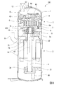
本発明の第一実施形態に係るスクロール圧縮機100について、図面を参照して説明する。図1に示すように、スクロール圧縮機100は、装置の外形をなすハウジング1と、ハウジング1内に設けられた圧縮部2と、この圧縮部2を駆動する駆動部3と、を有している。圧縮部2と駆動部3とは、軸線O1に沿って延びる回転軸4によって互いに接続されている。すなわち、駆動部3による回転エネルギーは、この回転軸4を通じて圧縮部2に即時に伝達される。圧縮部2は、この回転エネルギーによって作動流体を圧縮して高圧状態で外部に吐出する。高圧の作動流体は、例えば空調機器等における冷媒として利用される。以下、各部の構成について詳細に説明する。
First Embodiment
A
ハウジング1には、外部から作動流体としての冷媒ガスを吸入する吸入配管11と、上記圧縮部2による圧縮を経て吐出チャンバ67内で高圧状態となった冷媒ガスを排出する吐出配管12と、が設けられている。
The
回転軸4は軸線O1を中心とした円柱状をなしている。詳しくは後述するが、この回転軸4は、メイン軸受部材9、及びサブ軸受部材77によってハウジング1内に支持されている。メイン軸受部材9と回転軸4の外周面との間にはメイン軸受75が取り付けられている。サブ軸受部材77と回転軸4の外周面との間にはサブ軸受76が取り付けられている。
The rotating
回転軸4の一方側の端部において、軸線O1に対してオフセットされた(偏心した)位置には、軸線O1とは異なる偏心軸線O2を中心として柱状をなす偏心軸5が設けられている。この偏心軸線O2は軸線O1と平行をなしている。より詳細には、この偏心軸5は、回転軸4の端部から軸線O1方向一方側に向かって突出する円柱状をなしている。したがって、回転軸4が軸線O1回りに回転している状態では、偏心軸5は回転軸4の軸線O1回りに公転する。また、図3(a)に示すように、偏心軸線O2の方向から見て、偏心軸5の外周面の一部は平坦状に形成されることで、軸側キー面51をなしている。詳しくは後述するが、この軸側キー面51には後述のブッシュアッセンブリ10におけるブッシュ101の内周面の一部が当接する。
At one end of the
圧縮部2は、固定スクロール6、及び旋回スクロール7と、を有している。ディスチャージカバー8、メイン軸受部材9は、ハウジング1の内部の空間を軸線O1方向に区画する略円盤状の部材である。ディスチャージカバー8とメイン軸受部材9とは軸線O1方向に互いに間隔を空けて配列されている。すなわち、ディスチャージカバー8とメイン軸受部材9との間には空間が形成される。固定スクロール6、及び旋回スクロール7は軸線O1方向から互いに対向した状態で前記空間内に配置される。なお、ディスチャージカバー8の中央部には、上記の吐出チャンバ67から高圧ガスの逆流を防ぐ吐出弁66が設けられている。
The
固定スクロール6は、ハウジング1内部に固定された略円盤状の部材である。旋回スクロール7は、この固定スクロール6に対して軸線O1方向から対向することで両者の間に圧縮室Cを形成する。より詳細には、固定スクロール6は、円盤状の端板61と、この端板61の一方側の面から軸線O1方向に立設された固定ラップ62と、を有している。端板61は、軸線O1におおむね直交する面に沿って延びている。固定ラップ62は、軸線O1方向から見て渦巻状に形成された壁体である。より具体的には、固定ラップ62は、端板61の中心回りに巻回された板状の部材で形成されている。一例として固定ラップ62は、軸線O1方向から見て該軸線O1を中心とするインボリュート曲線をなすように構成されることが望ましい。
The fixed scroll 6 is a substantially disk-shaped member fixed inside the
固定ラップ62の径方向外側には、端板61の外周に沿って筒状に延びる外周壁63が形成されている。さらに、外周壁63の軸線O1方向他方側の端縁には、径方向内側から外側に向かって広がる円環状のフランジ部64が設けられている。固定スクロール6は、フランジ部64を介してボルト等によってメイン軸受部材9に固定されている。さらに、固定スクロール6の渦巻の中央部には、固定スクロール吐出口65が形成されている。
An outer
旋回スクロール7は、円盤状の端板71と、この端板71における軸線O1方向他方側の面に設けられた渦巻状の旋回ラップ72と、を有している。この旋回ラップ72も、軸線O2を中心とするインボリュート曲線をなすように構成されることが望ましい。
The
さらに、旋回ラップ72は、上記の固定ラップ62に対して軸線O1方向から対向するとともに、軸線O1と交差する方向で互いに重なり合うように配置される。言い換えれば、固定ラップ62と旋回ラップ72とは互いに噛み合っている。このように噛み合った状態で、固定ラップ62と旋回ラップ72との間には一定の空間が形成される。詳しくは後述するが、この空間は旋回ラップ72の旋回に伴ってその容積が変化する。これにより、作動流体を圧縮することが可能とされている。
Furthermore, the turning wraps 72 are arranged to face the fixed
以上のように構成された旋回スクロール7は、軸線O1方向一方側から上記の回転軸4に対して、後述のブッシュアッセンブリ10を介して連結される。旋回ラップ72の端板71における軸線O1方向他方側の面には、円筒状のボス部73が形成されている。このボス部73の中心軸は、軸線O2と同軸となっている。ボス部73の内側の空間には、上記回転軸4に形成された偏心軸5が、ブッシュアッセンブリ10を介して軸線O1方向から嵌入される。
The
ブッシュアッセンブリ10は、偏心軸5の外周面を囲むように取り付けられる筒状のブッシュ101と、このブッシュ101の外周面から径方向外側(外周側)に張り出すリング部102と、リング部102のさらに外周側に設けられたウエイト部103と、を備えている。
The
ブッシュアッセンブリ10が偏心軸5に取り付けられた状態において、ブッシュ101は上記の偏心軸線O2と同軸をなす円筒状をなしている。さらに、図3(a)に示すように、ブッシュ101の内周側にはブッシュ側キー面104が形成されている。ブッシュ側キー面104は、偏心軸5に形成された上記の軸側キー面51と当接する。すなわち、偏心軸5に取り付けられたブッシュアッセンブリ10(ブッシュ101)においては、これら軸側キー面51とブッシュ側キー面104とが互いに当接することで、ブッシュアッセンブリ10(ブッシュ101)の偏心軸線O2回りの回動が規制される。
When the
リング部102は、図3(a)、又は図3(b)に示すように、上記のブッシュ101の偏心軸線O2方向他方側の外周面から外周側(径方向外側)に向かって張り出している。本実施形態では、このリング部102の偏心軸線O2方向他方側の端面は上記ブッシュ101の偏心軸線O2方向他方側の端面とおおむね面一をなしている。
As shown in FIG. 3A or FIG. 3B, the
ウエイト部103は、リング部102の外周側の端縁に設けられた部材である。詳しくは後述するが、旋回スクロール7が回転軸4(偏心軸5)に取り付けられた状態では、旋回スクロール7は回転軸4の軸線O1を中心として旋回可能とされている。この旋回スクロール7の旋回による遠心力は、ラップ部(固定ラップ62、旋回ラップ72)に付加される。そのため、回転数が大きくなるとラップ部が破損する可能性が懸念される。そこで、本実施形態に係るブッシュアッセンブリ10には、この遠心力を軽減することを目的として、比較的に大きな重量を有するウエイト部103が設けられている。
The
このウエイト部103はリング部102の外周面に一体に形成される。図3(a)、図3(b)に示すように、偏心軸線O2方向から見てウエイト部103の断面はおおむね円弧状をなしている。具体的には、ウエイト部103の内周面は上記リング部102の外周面がなす円弧におおむね沿って延びる。一方で、ウエイト部103の外周面は、内周面から径方向に離間した位置で同じく円弧状に延びている。
The
さらに、ウエイト部103はリング部102を基準として、偏心軸線O2方向の両側にそれぞれ延びている。本実施形態では、このウエイト部103における偏心軸線O2方向の一方側の領域は、他方側の領域よりも、偏心軸線O2方向における寸法が大きく設定されている。
Further, the
なお、ブッシュアッセンブリ10が偏心軸5に取り付けられた状態においては、ウエイト部103は回転軸4の軸線O1方向一方側の端面上において、偏心軸5とは離間する側に位置している。より詳細には、偏心軸5の偏心軸線O2と回転軸4の軸線O1とを結ぶ直線上で、軸線O1を挟んで偏心軸線O2とは反対側の位置にウエイト部103が位置している。これにより、旋回スクロール7の旋回に伴う軸線O1回りの遠心力が軽減される。
In the state where the
以上のように構成されたブッシュアッセンブリ10が、図2に示すように偏心軸5に取り付けられる。より具体的には、ブッシュアッセンブリ10のブッシュ101が偏心軸5に対して嵌合される。このとき、偏心軸5の軸側キー面51と、ブッシュ101に形成されたブッシュ側キー面104とが互いに当接することで、ブッシュ101(ブッシュアッセンブリ10)は偏心軸5に対して回動不能に固定される。
The
さらに、ブッシュ101は旋回スクロール7のボス部73内側に設けられた軸受74に挿入される。図2に示すように軸受74は軸線O1方向に延びる筒状をなしている。本実施形態では、この軸受74が旋回スクロール7のボス部73に対して固定される一方で、軸受74の内周面はブッシュ101の外周面に対して摺接可能とされている。すなわち、ブッシュアッセンブリ10(ブッシュ101)は、旋回スクロール7のボス部73に対して回転可能とされている。
Further, the
上記のように軸受74の内周面とブッシュ101の外周面とは互いに摺接するため、これら部材には適切な潤滑が求められる。そこで、本実施形態では、ブッシュアッセンブリ10の各部に潤滑油を供給、又は排出するための潤滑油流路106が形成されている。
As described above, since the inner peripheral surface of the
潤滑油流路106は、ブッシュ101の外周面に形成された第一溝部107と、リング部102に形成された第二溝部108と、ウエイト部103に形成された排出部109と、を有している。
The lubricating
第一溝部107は、図3(a)、図4、図5に示すように、ブッシュ101の外周面から径方向内側に向かって凹没する溝である。この第一溝部107は、ブッシュ101の偏心軸線O2方向一方側から他方側に向かって直線状に延びている。特に、図3(a)に示すように、ブッシュ101の周方向における第一溝部107の両端縁(すなわち、第一溝部107の側壁と、ブッシュ101の外周面とによって形成される稜線部)は、わずかに径方向内側に向かって面取りされることで面取り部Rとされている。ブッシュ101の外周面と軸受74の内周面との間に介在する潤滑油は、この面取り部Rを通じて第一溝部107内に流入する。
The
さらに、図3(a)、及び図4に示すように、第一溝部107は軸線O1方向(偏心軸線O2方向)から見て、ウエイト部103がなす円弧の周方向における一方側に偏った位置に形成されている。詳しくは後述するが、本実施形態に係るスクロール圧縮機100では、軸線O1方向一方側から見て回転軸4が反時計回りに回転駆動される。この回転軸4の回転方向を基準とした場合、上記の第一溝部107は、軸線O1方向一方側から見てウエイト部103の回転方向前方側の領域に形成される。
Furthermore, as shown in FIG. 3A and FIG. 4, the
第二溝部108は、リング部102の径方向内側から径方向外側に向かって延びる凹溝である。より詳細には、図4又は図6に示すように、第二溝部108はリング部102の軸線O1方向他方側の面から一方側に向かって形成されている。さらに、第二溝部108は上記の第一溝部107における軸線O1方向他方側の端部から直線状に延びている。
The
特に、本実施形態では第二溝部108は、偏心軸線O2の径方向に対して上記の回転方向後方側に傾斜している。言い換えると、第二溝部108は、偏心軸線O2の径方向内側から外側に向かうにしたがって、ブッシュアッセンブリ10の回転方向後方側に向かって傾斜するように延びている。ブッシュ101の外周面上で第一溝部107が設けられる位置における接線Lに対して、第二溝部108は角度θをもって傾斜しており、角度θの値は、90°を超える値とされる。本実施形態では、第二溝部108は上記の接線Lに対しておおむね100°傾斜している。
In particular, in the present embodiment, the
排出部109は、上記の第二溝部108の径方向外側の端部に連通するとともに、ウエイト部103を径方向に貫通する切欠き(切欠き部109A)である。具体的には図5、又は図6に示すように、排出部109は偏心軸線O2方向において第二溝部108の径方向外側の端縁から、該偏心軸線O2方向の他方側に向かってウエイト部103を貫通している。言い換えれば、偏心軸線O2と交差する方向における断面視で、第二溝部108、及び排出部109は、おおむねL字型をなしている。
The
さらに、上記の回転軸4(偏心軸5)には、給油ポンプ80から潤滑油が供給される。この潤滑油はブッシュアッセンブリ10のブッシュ101と、旋回スクロール7の軸受74との間を潤滑した後、上記の潤滑油流路106によって回収・排出される。
以上のように構成されたブッシュアッセンブリ10によって旋回スクロール7が回転軸4上で支持される。
Further, lubricating oil is supplied from the
The
なお、メイン軸受部材9には旋回スクロール7の自転(偏心軸線O2回りの回転)を規制するためのオルダムリング91が設けられている。詳しくは図示しないが、このオルダムリング91には、旋回スクロール7の端板71に形成された溝に嵌合する突起が形成されている。さらに、オルダムリング91から見て径方向内側には、スラスト軸受92が設けられている。このスラスト軸受92は、旋回スクロール7による軸線O1方向の荷重を支持する。
The
以上のように構成された圧縮部2は、上記のメイン軸受部材9を隔ててハウジング1内に配置された駆動部3によって駆動される。図1に示すように、駆動部3は外部から供給される電力によって回動する電動モータが好適に用いられる。
The
次に、本実施形態に係るスクロール圧縮機100の動作について説明する。スクロール圧縮機100の運転を開始するに当たっては、まず上記の駆動部3に通電することで、回転軸4が軸線O1回りに回転駆動される。なお、本実施形態においては、軸線O1方向一方側から見て回転軸4の回転方向は反時計回りとされる。
Next, the operation of the
回転軸4の回転に伴って、上記の偏心軸5は軸線O1回りに公転し、これに取り付けられた旋回スクロール7は軸線O1を中心として旋回する。ここで、旋回スクロール7は、上述のオルダムリング91によって自転が規制されている。したがって、旋回スクロール7は回転軸4の軸線O1を中心として、偏心軸線O2の描く軌跡に沿って円運動(旋回)する。この旋回に伴って、旋回スクロール7の旋回ラップ72は、固定スクロール6の固定ラップ62に対して連続的な相対移動を繰り返す。この相対移動によって、固定ラップ62と旋回ラップ72との間に形成される圧縮室Cの容積が時間変化する。
As the
詳しくは図示しないが、まず旋回スクロール7の旋回中に、旋回ラップ72(及び固定ラップ62)の径方向外側に生じた開口から、作動流体としての冷媒ガスが圧縮室C内に導入される。旋回スクロール7の旋回に伴って、上記の開口は閉塞される。これにより、冷媒ガスは圧縮室C内に閉じ込められる。続いて、なおも旋回スクロール7が旋回することで、冷媒ガスは径方向内側(すなわち、偏心軸線O2側)に向かって移動する。このとき、旋回ラップ72と固定ラップ62は上記の渦巻状をなしていることから、両者によって形成される圧縮室Cの容積は、径方向内側に向かうに従って縮小する。これにより、冷媒ガスが圧縮される。最終的に旋回スクロール7(又は固定スクロール6)の中心部付近で、冷媒ガスは最高圧に達した後、上記の固定スクロール吐出口65、及びハウジング1の吐出配管12を通じて外部に供給される。
Although not shown in detail, the refrigerant gas as the working fluid is first introduced into the compression chamber C from the opening formed radially outward of the orbiting wrap 72 (and the fixed wrap 62) while the
次に、本実施形態におけるブッシュアッセンブリ10の動作について詳細に説明する。上記のようにブッシュアッセンブリ10には、給油ポンプ80から潤滑油が連続的に供給される。これにより、特にブッシュアッセンブリ10におけるブッシュ101の外周面と、軸受74の内周面との間が潤滑される。
Next, the operation of the
ここで、上記ブッシュ101の外周面と、軸受74の内周面との間は、スクロール圧縮機100の運転中を通じて、常態的に摺接状態にある。このため、潤滑油の温度上昇やこれに伴う粘度低下が生じる可能性がある。しかしながら、本実施形態に係るスクロール圧縮機100では、ブッシュアッセンブリ10に対して新たな潤滑油が連続的に供給されるため、上記のような温度上昇や粘度低下が発生する可能性を低減することができる。
Here, the outer peripheral surface of the
一方で、上記のように潤滑油を連続的に供給し続けるためには、ブッシュアッセンブリ10の潤滑に供された潤滑油を外部に連続的に排出し続ける必要がある。本実施形態に係るブッシュアッセンブリ10では、上述の潤滑油流路106が形成されていることから、潤滑油を連続的かつ円滑に排出し続けることができる。
On the other hand, in order to continuously supply the lubricating oil as described above, it is necessary to continuously discharge the lubricating oil provided to lubricate the
具体的には、まずブッシュ101に設けられた第一溝部107によって、ブッシュ101の外周面と軸受74の内周面との間に介在する潤滑油の一部が捕捉される。第一溝部107内に導かれた潤滑油は、重力の作用によって偏心軸線O2方向他方側に向かって流れた後、リング部102の第二溝部108の径方向内側の端部に到達する。
Specifically, first, a part of the lubricating oil interposed between the outer peripheral surface of the
第二溝部108に到達した潤滑油は、ブッシュアッセンブリ10の回転に伴う遠心力によって径方向外側に向かって流動する。第二溝部108の径方向外側の端部に達した潤滑油は、ウエイト部103に形成された排出部109に沿って偏心軸線O2方向他方側に流動した後、外部(例えば上記のメイン軸受部材9上)に排出される。なお、本実施形態では、メイン軸受部材9を軸線O1の径方向内側から外側にかけて貫通する孔(排油孔93)が形成されている。この排油孔93を経て排出部109から排出された潤滑油は、ハウジング1内の下部に貯留された後、給油ポンプ80によって再循環される。
以上のように、第一溝部107、第二溝部108、及び排出部109を通じて潤滑油を円滑に排出することができる。
The lubricating oil that has reached the
As described above, the lubricating oil can be smoothly discharged through the
特に、第一溝部107の開口における稜線部には、上記のように面取り部Rが形成されていることから、軸受74の内周面との間に介在する潤滑油を第一溝部107内に向けて円滑に導くことができる。一方で、この面取り部Rが設けられていない場合(すなわち、第一溝部107の開口における稜線が鋭角的に形成されている場合)、第一溝部107内に潤滑油を導くことが難しいのみならず、連続的な運用に伴って上記稜線から摩耗が進行して、ブッシュアッセンブリ10の芯ずれを生じる可能性がある。しかしながら、本実施形態では面取り部Rが形成されていることにより、このような摩耗や芯ずれ等が生じる可能性を低減することができる。
In particular, since the chamfered portion R is formed in the ridge line portion at the opening of the
さらに、第二溝部108は上記のようにブッシュアッセンブリ10の回転方向前方側から後方側に向かって傾斜している。特に、第二溝部108はブッシュ101の接線Lに対して90°を超える値をもって傾斜している。これにより、第二溝部108の径方向内側の端部は、ブッシュアッセンブリ10の回転方向前方側を向く。したがって、ブッシュアッセンブリ10の回転に伴って、第二溝部108内に向けて潤滑油を円滑に導くことができる。
Furthermore, the
さらに、排出部109は、ウエイト部103を径方向に貫通するとともに、軸線O1方向(又は偏心軸線O2方向)に延びる切欠き部109Aとされている。このような構成によれば、例えば排出部109をウエイト部103に形成された孔によって構成した場合に比べて、排出部109を通過する潤滑油の流量を十分に大きく確保できる。これにより、ブッシュアッセンブリ10における排油不良の可能性をさらに低減することができる。
Furthermore, the
他方で、上記の第二溝部108、排出部109を設けない場合、第一溝部107に導かれた潤滑油は外部に容易には排出されず、軸受74の冷却に十分な潤滑油を供給できなくなるため、ブッシュアッセンブリ10の回転に伴って軸受74の温度が次第に上昇し、最終的には軸受74の焼き付きにより圧縮機の故障を招く可能性がある。
On the other hand, when the
しかしながら、本実施形態に係るスクロール圧縮機100では、上記第一溝部107に連通する第二溝部108、及び排出部109が形成されていることから、潤滑油の円滑な排出を維持することができる。これにより、スクロール圧縮機100を長期にわたって安定的に運転することができる。
However, in the
[第二実施形態]
次に、本発明の第二実施形態について図7を参照して説明する。本実施形態ではウエイト部103を貫通する孔(貫通孔109B)が、上記潤滑油流路106における排出部109をなしている。すなわち、排出部109の偏心軸線O2方向他方側の端縁は開放されていない。
Second Embodiment
Next, a second embodiment of the present invention will be described with reference to FIG. In the present embodiment, a hole (through
このような構成によれば、上記第一実施形態における切欠き部109Aを排出部109とした場合に比して、ウエイト部103の重量減少を最小限にとどめることができる。すなわち、ウエイト部103の重量をより大きく確保することができる。これにより、潤滑油の円滑な排出に加えて、旋回スクロール7の旋回による軸線O1回りの振れ回りや振動をさらに抑制することができる。
According to such a configuration, weight reduction of the
以上、本発明の各実施形態について図面を参照して説明した。しかしながら、上記実施形態はあくまで一例に過ぎず、各部の構成を必要に応じて変更、改修することが可能である。
例えば、上記の各実施形態では、第二溝部108はリング部102の偏心軸線O2方向における他方側に設けられるととともに、排出部109は同じく偏心軸線O2の他方側に向かって形成される例について説明した。しかしながら、第二溝部108、排出部109が設けられる位置は上記構成に限定されない。一例として、第二溝部108がリング部102の偏心軸線O2方向の一方側(すなわち、旋回スクロール7に臨む側)に形成されるとともに、排出部109が該第二溝部108から偏心軸線O2方向の一方側に向かって形成される構成を採ることも可能である。
The embodiments of the present invention have been described above with reference to the drawings. However, the said embodiment is only an example to the last, and can change and modify the structure of each part as needed.
For example, in the above embodiments, the
さらに、上記の実施形態では、ブッシュアッセンブリ10に潤滑油流路106(第一溝部107、第二溝部108、排出部109)が1つのみ設けられる構成について説明した。しかしながら、スクロール圧縮機100の回転数や運転時間等の環境条件、仕様に応じて、上記潤滑油流路106を複数設けることも可能である。具体的には、上記の実施形態において説明した潤滑油流路106に対して、ブッシュ101(ウエイト部103)の周方向に間隔を空けて他の潤滑油流路106を設ける構成が考えられる。
Furthermore, in the above embodiment, the configuration in which only one lubricating oil flow path 106 (the
このような構成によれば、ブッシュアッセンブリ10の潤滑に供された潤滑油の排出と、給油ポンプ80から供給される新たな潤滑油との入れ替えを比較的早いサイクルで行うことができるため、さらに良好な潤滑性能を得ることができる。
According to such a configuration, the discharge of the lubricating oil provided to lubricate the
加えて、上記の各実施形態では、ウエイト部103がリング部102を基準として偏心軸線O2方向の両側に延びる構成について説明した。しかしながら、ウエイト部103の構成はこれに限定されず、例えば図8に示すように、ウエイト部103がリング部102の外周端縁から偏心軸線O2方向の一方側のみに延びる構成とすることも可能である。要するに、このようなウエイト部103の形状、寸法は、種々の設計条件、仕様に応じて適宜に選択されるが、いずれの態様であっても、上記各実施形態に係る潤滑油流路106を形成することが可能である。
In addition, in each of the above-described embodiments, the configuration in which the
1…ハウジング 2…圧縮部 3…駆動部(電動モータ) 4…回転軸(主軸) 5…偏心軸 6…固定スクロール 7…旋回スクロール 8…ディスチャージカバー 9…メイン軸受部材10…ブッシュアッセンブリ 11…吸入配管 12…吐出配管 31…ロータバランスウエイト 51…軸側キー面 61…端板 62…固定ラップ 63…外周壁 64…フランジ部 65…固定スクロール吐出口 66…吐出弁 67…吐出チャンバ 71…端板 72…旋回ラップ 73…ボス部 74…軸受(旋回スクロール) 75…メイン軸受 76…サブ軸受 77…サブ軸受部材 80…給油ポンプ 91…オルダムリング 92…スラスト軸受 93…排油孔 100…スクロール圧縮機 101…ブッシュ 102…リング部 103…ウエイト部 104…ブッシュ側キー面 106…潤滑油流路 107…第一溝部 108…第二溝部 109…排出部 109A…切欠き部 109B…貫通孔 C…圧縮室 L…接線 O1…軸線 O2…偏心軸線 R…面取り部 θ…角度
DESCRIPTION OF
Claims (3)
前記軸線に対してオフセットされた位置で該軸線回りに旋回可能に設けられた旋回スクロールと、
前記旋回スクロールと対向することで冷媒を圧縮する圧縮室を形成する固定スクロールと、
前記回転軸に設けられて、前記旋回スクロールを回転可能に支持するブッシュアッセンブリと、
を備え、
前記ブッシュアッセンブリ)は、
前記回転軸に固定され、前記軸線に対してオフセットされた位置で前記旋回スクロールを回転可能に支持するブッシュと、
該ブッシュの外周面から外周側に張り出すように設けられたリング部と、
該リング部の外周側に設けられて、前記ブッシュの周方向に円弧状に延びるウエイト部と、
を備え、
前記ブッシュの外周面から前記軸線の径方向内側に向かって凹没するとともに、該軸線に沿って延びる第一溝部と、
前記リング部の径方向内側から径方向外側に延びるとともに前記第一溝部に連通する第二溝部と、
前記ウエイト部を径方向に貫通するとともに、前記第二溝部の径方向外側の端部に連通する排出部と、
が形成され、
前記第二溝部は、前記軸線の径方向内側から径方向外側に向かうにしたがって、前記回転軸の回転方向後方側に延びるスクロール圧縮機。 An axis of rotation extending along the axis and rotating about the axis;
A orbiting scroll provided to be orbitable about the axis at a position offset with respect to the axis;
A fixed scroll forming a compression chamber for compressing the refrigerant by facing the orbiting scroll;
A bush assembly provided on the rotating shaft and rotatably supporting the orbiting scroll;
Equipped with
The bush assembly)
A bush fixed to the rotating shaft and rotatably supporting the orbiting scroll at a position offset with respect to the axis;
A ring portion provided so as to project outward from the outer peripheral surface of the bush;
A weight portion provided on the outer peripheral side of the ring portion and extending in an arc shape in the circumferential direction of the bush;
Equipped with
A first groove that is recessed from the outer peripheral surface of the bush toward the radially inner side of the axis, and extends along the axis;
A second groove extending radially outward from a radially inner side of the ring portion and in communication with the first groove;
A discharge portion which penetrates the weight portion in the radial direction and which is in communication with the radial outer end of the second groove;
Formed ,
The second groove portion is a scroll compressor that extends rearward in the rotational direction of the rotary shaft as it goes from the radially inner side to the radially outer side of the axis .
Priority Applications (2)
| Application Number | Priority Date | Filing Date | Title |
|---|---|---|---|
| JP2015109761A JP6550645B2 (en) | 2015-05-29 | 2015-05-29 | Scroll compressor |
| EP16169974.9A EP3103959B1 (en) | 2015-05-29 | 2016-05-17 | Scroll compressor |
Applications Claiming Priority (1)
| Application Number | Priority Date | Filing Date | Title |
|---|---|---|---|
| JP2015109761A JP6550645B2 (en) | 2015-05-29 | 2015-05-29 | Scroll compressor |
Publications (2)
| Publication Number | Publication Date |
|---|---|
| JP2016223351A JP2016223351A (en) | 2016-12-28 |
| JP6550645B2 true JP6550645B2 (en) | 2019-07-31 |
Family
ID=56008554
Family Applications (1)
| Application Number | Title | Priority Date | Filing Date |
|---|---|---|---|
| JP2015109761A Active JP6550645B2 (en) | 2015-05-29 | 2015-05-29 | Scroll compressor |
Country Status (2)
| Country | Link |
|---|---|
| EP (1) | EP3103959B1 (en) |
| JP (1) | JP6550645B2 (en) |
Families Citing this family (6)
| Publication number | Priority date | Publication date | Assignee | Title |
|---|---|---|---|---|
| JP6773152B2 (en) * | 2019-02-28 | 2020-10-21 | ダイキン工業株式会社 | Scroll compressor |
| WO2021203636A1 (en) * | 2020-04-07 | 2021-10-14 | 艾默生环境优化技术(苏州)有限公司 | Scroll compressor |
| JP2022026427A (en) * | 2020-07-31 | 2022-02-10 | 株式会社小松製作所 | Guide device |
| DE102021206432A1 (en) | 2021-06-22 | 2022-12-22 | Brose Fahrzeugteile SE & Co. Kommanditgesellschaft, Würzburg | scroll machine |
| CN115306719B (en) * | 2022-08-17 | 2024-03-08 | 广东美的环境科技有限公司 | Shafting subassembly, compressor and air conditioning system |
| WO2024069770A1 (en) * | 2022-09-27 | 2024-04-04 | 日立ジョンソンコントロールズ空調株式会社 | Compressor and air conditioner |
Family Cites Families (7)
| Publication number | Priority date | Publication date | Assignee | Title |
|---|---|---|---|---|
| JPS59115488A (en) | 1982-12-22 | 1984-07-03 | Hitachi Ltd | Bearing device for enclosed type scroll compressor |
| JPH07127584A (en) * | 1993-10-29 | 1995-05-16 | Toyota Autom Loom Works Ltd | Scroll type compressor |
| JP2868998B2 (en) * | 1994-03-14 | 1999-03-10 | 株式会社デンソー | Scroll compressor |
| US6082495A (en) * | 1998-02-25 | 2000-07-04 | Copeland Corporation | Scroll compressor bearing lubrication |
| JP4103225B2 (en) * | 1998-06-24 | 2008-06-18 | 株式会社日本自動車部品総合研究所 | Compressor |
| JP2002161879A (en) * | 2000-11-30 | 2002-06-07 | Toyota Industries Corp | Scroll compressor |
| JP2003286975A (en) * | 2002-03-27 | 2003-10-10 | Mitsubishi Electric Corp | Scroll compressor |
-
2015
- 2015-05-29 JP JP2015109761A patent/JP6550645B2/en active Active
-
2016
- 2016-05-17 EP EP16169974.9A patent/EP3103959B1/en active Active
Also Published As
| Publication number | Publication date |
|---|---|
| JP2016223351A (en) | 2016-12-28 |
| EP3103959A1 (en) | 2016-12-14 |
| EP3103959B1 (en) | 2017-11-29 |
Similar Documents
| Publication | Publication Date | Title |
|---|---|---|
| JP6550645B2 (en) | Scroll compressor | |
| JP6187123B2 (en) | Scroll compressor | |
| KR101364025B1 (en) | Scroll compressor with supporting member in axial direction | |
| KR20080089288A (en) | Scroll fluid machine | |
| JP7075407B2 (en) | Scroll compressor | |
| KR20100042170A (en) | Scoroll compressor and refrigerator having the same | |
| KR20160017539A (en) | compressor | |
| US20170002816A1 (en) | Scroll compressor | |
| JP6664879B2 (en) | Open type compressor | |
| JP6554926B2 (en) | Scroll compressor | |
| KR20080054849A (en) | Oil supply structure for scroll compressor | |
| JP2008180094A (en) | Scroll-type fluid machine | |
| JP2011174453A (en) | Scroll compressor | |
| JPH05149274A (en) | Scroll type compressor | |
| JP2006241993A (en) | Scroll compressor | |
| JP2009127517A (en) | Enclosed compressor | |
| JP2008274877A (en) | Hermetic compressor | |
| KR100830943B1 (en) | Oil supply structure of scroll compressor | |
| JP2007247567A (en) | Scroll compressor | |
| JP7186055B2 (en) | scroll compressor | |
| JP3574904B2 (en) | Closed displacement compressor | |
| KR20100058821A (en) | Eccentric bush and scroll type compressor having the same | |
| KR101964961B1 (en) | Compressor having structure of gradually changing oil path area | |
| JP2008309150A (en) | Scroll compressor | |
| JP4935511B2 (en) | Scroll compressor |
Legal Events
| Date | Code | Title | Description |
|---|---|---|---|
| A621 | Written request for application examination |
Free format text: JAPANESE INTERMEDIATE CODE: A621 Effective date: 20180216 |
|
| A711 | Notification of change in applicant |
Free format text: JAPANESE INTERMEDIATE CODE: A712 Effective date: 20180702 |
|
| A131 | Notification of reasons for refusal |
Free format text: JAPANESE INTERMEDIATE CODE: A131 Effective date: 20181127 |
|
| A977 | Report on retrieval |
Free format text: JAPANESE INTERMEDIATE CODE: A971007 Effective date: 20181122 |
|
| A521 | Written amendment |
Free format text: JAPANESE INTERMEDIATE CODE: A523 Effective date: 20190104 |
|
| TRDD | Decision of grant or rejection written | ||
| A01 | Written decision to grant a patent or to grant a registration (utility model) |
Free format text: JAPANESE INTERMEDIATE CODE: A01 Effective date: 20190604 |
|
| A61 | First payment of annual fees (during grant procedure) |
Free format text: JAPANESE INTERMEDIATE CODE: A61 Effective date: 20190612 |
|
| R150 | Certificate of patent or registration of utility model |
Ref document number: 6550645 Country of ref document: JP Free format text: JAPANESE INTERMEDIATE CODE: R150 |