JP6545005B2 - Linear actuator - Google Patents
Linear actuator Download PDFInfo
- Publication number
- JP6545005B2 JP6545005B2 JP2015115712A JP2015115712A JP6545005B2 JP 6545005 B2 JP6545005 B2 JP 6545005B2 JP 2015115712 A JP2015115712 A JP 2015115712A JP 2015115712 A JP2015115712 A JP 2015115712A JP 6545005 B2 JP6545005 B2 JP 6545005B2
- Authority
- JP
- Japan
- Prior art keywords
- case
- linear actuator
- shaft
- reduction mechanism
- feed screw
- Prior art date
- Legal status (The legal status is an assumption and is not a legal conclusion. Google has not performed a legal analysis and makes no representation as to the accuracy of the status listed.)
- Expired - Fee Related
Links
Images


Landscapes
- Transmission Devices (AREA)
- Connection Of Motors, Electrical Generators, Mechanical Devices, And The Like (AREA)
Description
本発明は、送りねじ機構を備えたリニアアクチュエータに関し、特に、医療用機器や介護用機器等に用いられるリニアアクチュエータに関する。 The present invention relates to a linear actuator provided with a feed screw mechanism, and more particularly to a linear actuator used for medical equipment, care equipment and the like.
従来、医療用機器や介護用機器等には、患者や介護者等の負担を軽減するために、電動のリニアアクチュエータが用いられている。具体的には、リニアアクチュエータは、ベッドの昇降動作やリクライニング動作、さらには立ち上がり補助椅子の昇降動作等に用いられる。このような、リニアアクチュエータが、例えば、特許文献1に記載されている。
2. Description of the Related Art Conventionally, an electric linear actuator has been used for medical equipment, nursing equipment and the like in order to reduce the burden on patients and carers. Specifically, the linear actuator is used for raising and lowering operation and reclining operation of a bed, and further for raising and lowering operation of a rising assistant chair. Such a linear actuator is described, for example, in
特許文献1に記載されたリニアアクチュエータは、略棒状に形成されており、モータ装置,減速装置および直動装置(送りねじ機構)を備えている。これらのモータ装置,減速装置および直動装置は、それぞれ同軸上に配置されている。これにより、モータ装置の回転が減速装置により減速されて高トルク化され、高トルク化された出力が直動装置に伝達される。よって、比較的重量が嵩む駆動対象物を、容易に動作させることができる。
The linear actuator described in
そして、モータ装置を形成する電動モータは、モータケース内に収容され、減速装置を形成する減速機(減速機構)は、第1,第2の減速機ケース内に収容されている。また、直動装置を形成するシャフト(軸部材)は、補強筒の内部に収容され、補強筒は、縦割り形状の2部品よりなるケースに取り付けられている。 And the electric motor which forms a motor apparatus is accommodated in a motor case, and the reduction gear (reduction mechanism) which forms a reduction gear is accommodated in the 1st, 2nd reduction gear case. Further, the shaft (shaft member) forming the linear motion device is accommodated inside the reinforcing cylinder, and the reinforcing cylinder is attached to a case formed of two parts having a vertically split shape.
しかしながら、上述の特許文献1に記載されたリニアアクチュエータにおいては、減速機構と軸部材とを連結するジョイント機構がある部分に、1つの軸受が設けられている。そして、軸部材の軸方向に沿う減速機構側は、この1つの軸受のみによって回動自在に支持されている。
However, in the linear actuator described in
これにより、軸部材を傾斜させるような外力(曲げモーメント)がリニアアクチュエータに作用すると、軸部材の軸方向に沿う減速機構側が強度不足で抉られて、ジョイント機構が傾斜することが起こり得る。ジョイント機構が傾斜されると減速機構にもこの外力が伝達される。よって、減速機構を形成する複数の歯車の噛み合い状態が悪くなり、噛み合い状態が緩いと減速機の作動音が大きくなり、噛み合い状態がきついと減速機の作動抵抗が大きくなってしまう。 As a result, when an external force (bending moment) that causes the shaft member to tilt acts on the linear actuator, the reduction mechanism side along the axial direction of the shaft member may be twisted with insufficient strength, and the joint mechanism may be tilted. When the joint mechanism is inclined, this external force is also transmitted to the reduction gear mechanism. Therefore, the meshing state of the plurality of gears forming the speed reduction mechanism is deteriorated, and when the meshing state is loose, the operation noise of the reduction gear becomes large, and when the meshing state is tight, the operation resistance of the reduction gear becomes large.
本発明の目的は、軸部材に作用する曲げモーメントを減速機構に伝達させないようにして、スムーズな動作および低騒音化を実現し得るリニアアクチュエータを提供することにある。 An object of the present invention is to provide a linear actuator that can realize smooth operation and low noise without transmitting a bending moment acting on a shaft member to a reduction mechanism.
本発明の一態様では、回転軸を有するモータと、前記回転軸の回転を減速する減速機構と、前記減速機構の出力部材に連結される軸部材と、前記軸部材の雄ねじ部にねじ結合され、前記軸部材の回転に伴って前記軸部材の軸方向に移動される雌ねじ部材と、前記モータを収容するモータケースと、前記モータケースに接続され、前記減速機構を収容する減速機構ケースと、前記軸部材および前記雌ねじ部材を収容する送りねじ機構ケースと、前記雌ねじ部材に設けられ、前記送りねじ機構ケースに対して出入りするピストンと、前記減速機構ケースに装着され、前記出力部材を回動自在に支持する出力部材用軸受と、前記減速機構ケースと前記送りねじ機構ケースとを連結する連結部材と、を備えた。 In one aspect of the present invention, a motor having a rotating shaft, a reduction mechanism for reducing the rotation of the rotating shaft, a shaft member connected to an output member of the reduction mechanism, and an external thread of the shaft member are screwed. A female screw member moved in the axial direction of the shaft member with the rotation of the shaft member, a motor case accommodating the motor, and a reduction mechanism case connected to the motor case and accommodating the reduction mechanism. a feed screw mechanism case accommodating said shaft member and said female screw member, the provided female screw member, a piston and out to the feed screw mechanism case, is attached to the speed reduction mechanism casing, rotate the output member A bearing for an output member freely supported , and a connecting member for connecting the reduction gear case and the feed screw mechanism case are provided .
本発明の他の態様では、前記軸部材の軸方向に沿う前記出力部材側を、前記減速機構ケースに装着された少なくとも1つの軸部材用軸受に回動自在に支持させた。 In another aspect of the present invention, the output member side along the axial direction of the shaft member is rotatably supported by at least one shaft member bearing mounted on the reduction gear case.
本発明の他の態様では、前記軸部材用軸受を少なくとも2つ設け、前記2つの軸部材用軸受を、前記軸部材に装着されるカラーにより互いに離間させた。 In another aspect of the present invention, at least two bearings for shaft members are provided, and the two bearings for shaft members are separated from each other by a collar attached to the shaft members.
本発明の他の態様では、回転軸を有するモータと、前記回転軸の回転を減速する減速機構と、前記減速機構の出力部材に連結される軸部材と、前記軸部材の雄ねじ部にねじ結合され、前記軸部材の回転に伴って前記軸部材の軸方向に移動される雌ねじ部材と、前記モータを収容するモータケースと、前記モータケースに接続され、前記減速機構を収容する減速機構ケースと、前記軸部材および前記雌ねじ部材を収容する送りねじ機構ケースと、前記雌ねじ部材に設けられ、前記送りねじ機構ケースに対して出入りするピストンと、前記減速機構ケースに装着され、前記軸部材の軸方向に沿う前記出力部材側を回転自在に支持する少なくとも2つの軸部材用軸受と、前記減速機構ケースと前記送りねじ機構ケースとを連結する連結部材と、
を備えた。
In another aspect of the present invention, a motor having a rotating shaft, a reduction mechanism for reducing the rotation of the rotating shaft, a shaft member connected to an output member of the reduction mechanism, and a screw connection with an external thread of the shaft member A female screw member moved in the axial direction of the shaft member with the rotation of the shaft member, a motor case for housing the motor, and a reduction gear case connected to the motor case for housing the reduction gear mechanism , and the shaft member and the feed screw mechanism case accommodating the female screw member, the provided female screw member, a piston and out to the feed screw mechanism case, is attached to the speed reduction mechanism casing, the axis of said shaft member At least two shaft member bearings rotatably supporting the output member side along the direction, and a connecting member connecting the speed reduction mechanism case and the feed screw mechanism case;
Equipped .
本発明の他の態様では、前記少なくとも2つの軸部材用軸受を、前記軸部材に装着されるカラーにより互いに離間させた。 In another aspect of the present invention, the at least two shaft member bearings are separated from each other by a collar mounted on the shaft member.
本発明の他の態様では、前記出力部材を、前記減速機構ケースに装着された出力部材用軸受に回動自在に支持させた。 In another aspect of the present invention, the output member is rotatably supported by an output member bearing attached to the reduction mechanism case.
本発明によれば、出力部材を、ケースに装着された出力部材用軸受に回動自在に支持させたので、軸部材に作用する曲げモーメントを減速機構に伝達させないようにできる。 According to the present invention, since the output member is rotatably supported by the output member bearing attached to the case, the bending moment acting on the shaft member can be prevented from being transmitted to the speed reduction mechanism.
また、本発明によれば、軸部材の軸方向に沿う出力部材側を、ケースに装着された少なくとも2つの軸部材用軸受に回動自在に支持させたので、軸部材に作用する曲げモーメントを減速機構に伝達させないようにできる。 Further, according to the present invention, since the output member side along the axial direction of the shaft member is rotatably supported by at least two shaft member bearings mounted on the case, bending moment acting on the shaft member can be reduced. It can be prevented from being transmitted to the speed reduction mechanism.
したがって、リニアアクチュエータのスムーズな動作および低騒音化を実現できる。さらに、減速機構には大きな抉り力が掛からないため、減速機構の異常摩耗等を確実に抑制して、ひいてはリニアアクチュエータの長寿命化を図ることができる。 Therefore, smooth operation and low noise of the linear actuator can be realized. Furthermore, since no large rotational force is applied to the speed reduction mechanism, abnormal wear and the like of the speed reduction mechanism can be reliably suppressed, and consequently, the life of the linear actuator can be prolonged.
以下、本発明の実施の形態1について、図面を用いて詳細に説明する。
Hereinafter,
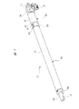
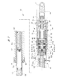
図1は本発明に係るリニアアクチュエータの斜視図を、図2は図1のリニアアクチュエータの長手方向に沿う断面図を、図3は図2のモータ部を拡大して示す拡大断面図を、図4(a)は図2のA−A線に沿う断面図、(b)は図2のB−B線に沿う断面図を、図5は図2の減速機構部を拡大して示す拡大断面図を、図6は送りねじ機構ケース,連結部材および減速機構ケースを示す斜視図をそれぞれ示している。 1 is a perspective view of the linear actuator according to the present invention, FIG. 2 is a sectional view along the longitudinal direction of the linear actuator of FIG. 1, and FIG. 3 is an enlarged sectional view showing the motor part of FIG. 4 (a) is a cross-sectional view taken along the line A-A in FIG. 2, (b) is a cross-sectional view taken along the line B-B in FIG. 2, and FIG. 5 is an enlarged cross-section showing the speed reduction mechanism of FIG. FIG. 6 is a perspective view showing the feed screw mechanism case, the connecting member and the reduction mechanism case, respectively.
図1に示すリニアアクチュエータ10は、電動モータを用いた送りねじ式のリニアアクチュエータであって、例えば、介護用ベッドの底板(図示せず)を起立または倒伏させるための駆動源として用いられる。リニアアクチュエータ10は、介護用ベッドのフレーム(図示せず)に装着され、手元スイッチ(図示せず)の操作により駆動される。
The
リニアアクチュエータ10は略棒状に形成され、その長手方向両端には、固定部11,12がそれぞれ設けられている。そして、各固定部11,12には、介護用ベッドのフレームや底板に設けられた固定ピン(図示せず)が回動自在に装着される。これにより、例えば、リニアアクチュエータ10を伸張させるように駆動することで底板が起立され、リニアアクチュエータ10を縮小させるように駆動することで底板が倒伏される。
The
図1に示すように、リニアアクチュエータ10は、駆動機構部20と送りねじ機構部50とを備えており、駆動機構部20および送りねじ機構部50は、それぞれ同軸上に配置され、連結部材60により所定の抜け強度を持って互いに連結されている。
As shown in FIG. 1, the
図2に示すように、駆動機構部20は、モータ部30と減速機構部40とから形成されている。モータ部30は、磁性材料により略円筒形状に形成されたモータケース(ケース)31を備えている。モータケース31の長手方向に沿う減速機構部40寄りの内壁には、断面が略円弧形状に形成された一対の永久磁石32(図示では1つのみ示す)が固定されている。ここで、永久磁石32の配置関係を判り易くするために、図示においては、永久磁石32に網掛けを施している。
As shown in FIG. 2, the
各永久磁石32の径方向内側には、所定隙間(エアギャップ)を介して、コイル33が巻装されたアーマチュア(回転子)34が回転自在に設けられている。また、アーマチュア34の回転中心には、アーマチュア軸(回転軸)35が貫通して固定されている。このように、モータケース31の内部には、アーマチュア34およびアーマチュア軸35が回転自在に収容されている。
An armature (rotor) 34 on which the
アーマチュア軸35のアーマチュア34よりも固定部11寄りの部分には、一対のブラシ36が摺接する整流子37が設けられている。また、整流子37には、コイル33の端部が電気的に接続されている。これにより、ブラシ36および整流子37を介して、アーマチュア34のコイル33に駆動電流が供給される。よって、アーマチュア34に電磁力が発生して、アーマチュア34はアーマチュア軸35とともに、所定の回転方向および回転数で回転する。ここで、各永久磁石32,コイル33,アーマチュア34,アーマチュア軸35,各ブラシ36,整流子37によって、本発明のモータを構成している。
At a portion closer to the fixed
図1に示すように、駆動機構部20の側方には、外部コネクタ(図示せず)が接続されるコネクタ接続部21が設けられている。そして、外部コネクタからは、手元スイッチからの操作信号に加えて、モータ部30(図2参照)を駆動するための駆動電流が供給されるようになっている。なお、コネクタ接続部21は、モータケース31の軸方向一側を閉塞するカバー部材38に固定されている。また、カバー部材38の軸方向一側に、固定部11が一体に設けられている。
As shown in FIG. 1, a
図2に示すように、アーマチュア軸35の軸方向一側(図中右側)は、第1軸受部材(玉軸受)39によって回動自在に支持されている。第1軸受部材39は、カバー部材38に固定されている。これにより、アーマチュア軸35の軸方向一側は、モータケース31の内部でがたつくこと無くスムーズに回転することができる。
As shown in FIG. 2, one side (right side in the figure) of the
アーマチュア軸35の軸方向他側(図中左側)は、減速機構部40を形成する減速機構ケース(ケース)41の内部にまで延ばされている。そして、アーマチュア軸35の軸方向他側は、第1減速機構43のサンギヤ43a(図5参照)を介して、減速機構ケース41に装着された第2軸受部材(玉軸受)42によって回動自在に支持されている。これにより、アーマチュア軸35の軸方向他側も、モータケース31の内部でがたつくこと無くスムーズに回転することができる。
The other axial direction side (left side in the drawing) of the
ここで、モータケース31,減速機構ケース41およびカバー部材38は、一対の締結ボルトBTにより一体に組み付けられている。なお、一対の締結ボルトBTは、モータケース31の内側でかつ径方向外側に配置され、さらにモータケース31内に対向するように設けられた一対の永久磁石32の間に配置されている。これにより、モータケース31が径方向に大型化(大径化)するのを抑制している。
Here, the
減速機構ケース41の内部で、かつ長手方向に沿う第2軸受部材42寄りの部分には、遊星歯車減速機よりなる第1減速機構(減速機構)43および第2減速機構(減速機構)44が収容されている。ここで、本実施の形態においては、所定の減速比に設定された第1減速機構43および第2減速機構44を2段に重ねることで、減速機構全体の径方向への大型化を抑えつつ、大きな減速比が得られるようにしている。これにより、モータ部30および減速機構部40の径方向への大型化を抑制して、駆動機構部20の径方向寸法を送りねじ機構部50の径方向寸法と略同じになるようにして、リニアアクチュエータ10の全体形状を、段差を無くしてストレート形状としている。
Inside the
図4(a)および図5に示すように、第1減速機構43は、アーマチュア軸35の軸方向他側に固定されたサンギヤ43aと、サンギヤ43aに噛合してサンギヤ43aの周囲を転動する3つのプラネタリギヤ43bと、各プラネタリギヤ43bを支持するキャリア43cと、減速機構ケース41の内壁に形成され、各プラネタリギヤ43bが噛合されるリングギヤ43dとを備えている。これにより、アーマチュア軸35の回転が減速されるとともに高トルク化され、キャリア43cから第2減速機構44に向けて出力される。
As shown in FIGS. 4A and 5, the first
また、図4(b)および図5に示すように、第2減速機構44は、第1減速機構43のキャリア43cに一体に設けたサンギヤ44aと、サンギヤ44aに噛合してサンギヤ44aの周囲を転動する3つのプラネタリギヤ44bと、各プラネタリギヤ44bを支持するキャリア(出力部材)44cと、減速機構ケース41の内壁に形成され、各プラネタリギヤ44bが噛合されるリングギヤ44dとを備えている。これにより、第1減速機構43のキャリア43cの回転が減速されるとともに高トルク化され、キャリア44cから送りねじ機構部50に向けて出力される。
Further, as shown in FIGS. 4B and 5, the second
ここで、第1減速機構43のリングギヤ43dおよび第2減速機構44のリングギヤ44dは、いずれも同じ大きさ(同じモジュール)の歯を備えている。したがって、減速機構ケース41の内壁に対してリングギヤ43d,44dを同時に成形することができ、リングギヤ43d,44dの成形作業が煩雑化することは無い。
Here, the
図2に示すように、減速機構ケース41の内部で、かつ長手方向に沿う送りねじ機構部50寄りの部分には、第3軸受部材(出力部材用軸受)45と第4軸受部材(軸部材用軸受)46とが同軸上に設けられている。
As shown in FIG. 2, a third bearing member (bearing for output member) 45 and a fourth bearing member (shaft member) are provided inside the reduction
第3軸受部材45は、外輪45a,内輪45bおよび複数の鋼球45cを有する玉軸受となっている。第3軸受部材45の外輪45aは、減速機構ケース41に装着されている。また、第3軸受部材45の内輪45bは、第2減速機構44のキャリア44cに固定されている。つまり、第3軸受部材45は、第2減速機構44のキャリア44cを回動自在に支持している。
The
このように、第1減速機構43のサンギヤ43aを第2軸受部材42に回動自在に支持させ、第2減速機構44のキャリア44cを第3軸受部材45に回動自在に支持させることで、減速機構ケース41の内部において、第1減速機構43および第2減速機構44(2段減速機構)を形成する歯車の噛み合いを滑らかにしている。よって、2段減速機構の作動音の低減や長寿命化が図れるとともに、モータ部30から送りねじ機構部50への動力伝達のロスが最小限に抑えられる。
Thus, the
第4軸受部材46は、外輪46a,内輪46bおよび複数の鋼球46cを有する玉軸受となっている。第4軸受部材46の外輪46aは、減速機構ケース41に装着されている。また、第4軸受部材46の内輪46bは、送りねじ機構部50を形成するシャフト52の軸方向一側、つまりシャフト52の軸方向に沿うキャリア44c側に固定されている。より具体的には、内輪46bは、シャフト52の軸方向一側にある小径装着部52aに固定されている。つまり、第4軸受部材46は、シャフト52の軸方向に沿うキャリア44c側を回動自在に支持している。
The
これにより、リニアアクチュエータ10の作動時において、シャフト52の軸方向一側の回転振れが効果的に抑制される。よって、リニアアクチュエータ10をスムーズに作動させることができ、当該リニアアクチュエータ10から発生する作動音が低減される。
Thereby, at the time of operation of the
ここで、シャフト52の軸方向一側には、インボリュートセレーション52bが設けられ、当該インボリュートセレーション52bは、第2減速機構44のキャリア44cに対して回転力を伝達可能に嵌合されている。これにより、キャリア44cからの駆動力が、シャフト52に効率良く伝達される。
Here, an
図2に示すように、送りねじ機構部50は、中空パイプよりなる送りねじ機構ケース(ケース)51を備えている。送りねじ機構ケース51は、モータケース31および減速機構ケース41に対して同軸上に設けられ、図1に示すように、モータケース31よりも長い長さ寸法とされている。具体的には、送りねじ機構ケース51の長さ寸法は、ピストンチューブ54の伸縮量によって決まる。
As shown in FIG. 2, the feed
図2に示すように、送りねじ機構ケース51の軸方向一側には、減速機構ケース41の小径本体部41aに嵌合される嵌合部51aが設けられている。ここで、嵌合部51aの厚み寸法t1は、減速機構ケース41の大径本体部41bと小径本体部41aとによって形成される段差寸法t2(図6参照)よりも若干小さい寸法に設定されている(t1<t2)。これにより、送りねじ機構ケース51と減速機構ケース41とを連結した際に、リニアアクチュエータ10の全体形状を略ストレート形状にできる。
As shown in FIG. 2, at one axial side of the feed
図2に示すように、送りねじ機構ケース51の内部には、第2減速機構44のキャリア44cによって回転されるシャフト(軸部材)52が回転自在に収容されている。シャフト52の外周部分には、雄ねじ部52cが形成されており、当該雄ねじ部52cには、スクリューナット(雌ねじ部材)53がねじ結合されている。つまり、スクリューナット53は、シャフト52の回転に伴って、シャフト52の軸方向に移動するようになっている。具体的には、シャフト52を正転させると、スクリューナット53は図中右側へ移動して、ひいてはリニアアクチュエータ10が縮小される。一方、シャフト52を逆転させると、スクリューナット53は図中左側へ移動して、ひいてはリニアアクチュエータ10が伸張される。
As shown in FIG. 2, a shaft (shaft member) 52 rotated by the
ここで、スクリューナット53の外周部分には、その軸方向に延びる凹溝(図示せず)が形成されている。一方、送りねじ機構ケース51の内周部分には、その軸方向に延びる凸部(図示せず)が形成されている。そして、スクリューナット53の凹溝と送りねじ機構ケース51の凸部とを、互いに摺動自在に凹凸係合させることで、シャフト52の回転によりスクリューナット53は回転せず、当該スクリューナット53はその軸方向のみに移動するようになっている。
Here, on the outer peripheral portion of the
スクリューナット53には、中空パイプよりなるピストンチューブ(ピストン)54の軸方向一側が固定されている。ピストンチューブ54は、送りねじ機構ケース51とシャフト52との間に設けられ、当該ピストンチューブ54は、送りねじ機構ケース51に対して出入り自在となっている。ここで、シャフト52,スクリューナット53およびピストンチューブ54によって、送りねじ機構を構成している。
One axial direction side of a piston tube (piston) 54 formed of a hollow pipe is fixed to the
ピストンチューブ54の外周側は、送りねじ機構ケース51の軸方向他側に固定されたチューブガイド55によって移動自在に支持されている。チューブガイド55は、固定キャップ56によって、送りねじ機構ケース51の軸方向他側に抜け止めされた状態で固定されている。
The outer peripheral side of the
シャフト52の軸方向他側には、ピストンチューブ54の内周側に摺接する環状の摺接部材57が設けられている。この摺接部材57は、シャフト52とともにピストンチューブ54の内部で回転するようになっている。ここで、摺接部材57の外周部分には、ピストンチューブ54に対する滑りをスムーズにする滑りリング(図示せず)が設けられている。なお、この滑りリングとしては、例えば、ポリテトラフルオロエチレン樹脂(PTFE)製のものが用いられる。また、摺接部材57は、ピストンチューブ54の軸心に対してシャフト52の軸心がずれないようにして、シャフト52の軸方向他側の回転振れを抑える機能も備えている。
On the other side in the axial direction of the
ピストンチューブ54の軸方向他側には、当該ピストンチューブ54の軸方向他側を閉塞するプラグ58が挿入されており、当該プラグ58はピストンチューブ54に対して相対回転不能に固定されている。プラグ58は固定部12を備えており、当該固定部12には介護用ベッドのフレームや底板に設けられた固定ピンが装着されるようになっている。
A
図5および図6に示すように、連結部材60は、鋼板よりなる管材を所定の長さに切断して筒状に形成され、その長さ寸法は、第1減速機構43および第2減速機構44を2段に重ねた長さ寸法よりも若干短い長さ寸法に設定されている。連結部材60は、減速機構ケース41と送りねじ機構ケース51とを連結するもので、連結部材60の軸方向一側には、当該連結部材60の径方向から対向するようにして2つの第1係合爪61が設けられている。
As shown in FIGS. 5 and 6, the connecting
また、連結部材60の軸方向他側には、当該連結部材60の径方向から対向するようにして2つの第2係合爪62が設けられている。これらの第1,第2係合爪61,62は、連結部材60の板厚方向にプレス加工を施すことで、連結部材60の一部を切り起こして形成されている。
Further, on the other side in the axial direction of the connecting
各第1係合爪61は、連結部材60の軸方向に沿う送りねじ機構ケース51側に向けて突出されている。一方、各第2係合爪62は、連結部材60の軸方向に沿う減速機構ケース41側に向けて突出されている。つまり、第1,第2係合爪61,62の先端側は、連結部材60の軸方向に沿って互いに向き合わされている。また、第1,第2係合爪61,62の先端側は、第1,第2係合爪61,62を形成する際に、連結部材60の径方向内側に予め折り曲げられている。
Each
そして、リニアアクチュエータ10を組み立てた状態のもとで、各第1係合爪61は、減速機構ケース41の大径本体部41bの外周部分に形成された第1環状溝41cに係合される。一方、各第2係合爪62は、送りねじ機構ケース51の嵌合部51aの外周部分に形成された第2環状溝51bに係合される。
Then, in a state where the
次に、以上のように形成したリニアアクチュエータ10の組み立て手順について、特に、連結部材60を用いた駆動機構部20と送りねじ機構部50との連結手順について、図面を用いて詳細に説明する。
Next, an assembling procedure of the
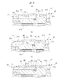
図7(a),(b),(c)は連結部材の減速機構ケースへの組付手順を説明する部分拡大断面図を、図8(a),(b),(c)は連結部材が組み付けられた減速機構ケースに対する送りねじ機構の組付手順を説明する部分拡大断面図をそれぞれ示している。 7 (a), (b) and (c) are partial enlarged cross-sectional views for explaining the assembling procedure of the connecting member to the reduction mechanism case, and FIGS. 8 (a), (b) and (c) are the connecting member The partial enlarged sectional view which respectively demonstrates the assembly procedure of the feed screw mechanism with respect to the speed-reduction mechanism case which was assembled is shown.
図7(a)の破線矢印M1に示すように、まず、連結部材60の各第1係合爪61側を、減速機構ケース41の大径本体部41bに臨ませる。次いで、図7(b)に示すように、連結部材60の軸心と減速機構ケース41の軸心とを一致させた状態のもとで、連結部材60を大径本体部41bに嵌合させていく。これにより、破線矢印M2に示すように各第1係合爪61が弾性変形され、当該状態のもとで連結部材60が大径本体部41bに嵌合されていく。
As shown by the broken line arrow M1 in FIG. 7A, first, the first
その後、図7(c)に示すように、両者の嵌合を継続して進めていくことで、連結部材60の軸方向一側が、減速機構ケース41の第1ストッパ壁41dに当接する。これに伴い、大径本体部41bにより弾性変形されていた各第1係合爪61が、破線矢印M3に示すように元に戻って第1環状溝41cに係合される。これにより、連結部材60の減速機構ケース41(駆動機構部20)への組み付けが完了する。
Thereafter, as shown in FIG. 7C, by continuously advancing the fitting of the two, one axial direction side of the connecting
これにより、減速機構ケース41に対して連結部材60を一方向からスライドさせるだけで、減速機構ケース41に連結部材60をワンタッチで組み付けることができる。また、各第1係合爪61の先端側が、連結部材60の減速機構ケース41に対する抜け方向に対し、突っ張るようにして第1環状溝41cに係合するので、十分な抜け強度を確保することができる。
Thus, the
次に、図8(a)の破線矢印M4に示すように、連結部材60が組み付けられた減速機構ケース41に対して、送りねじ機構ケース51の嵌合部51aを臨ませる。このとき、送りねじ機構部50の軸心と減速機構ケース41との軸心とを一致させた状態としつつ、減速機構ケース41の小径本体部41aと連結部材60との間の環状隙間CSに、嵌合部51aを挿入するようにする。これにより、図8(b)の破線矢印M5に示すように、各第2係合爪62が弾性変形され、当該状態のもとで嵌合部51aが小径本体部41aに嵌合されていく。
Next, as shown by the broken line arrow M4 in FIG. 8A, the
その後、図8(c)に示すように、両者の嵌合を継続して進めていくことで、嵌合部51aの軸方向一側が、減速機構ケース41の第2ストッパ壁41eに当接する。これに伴い、嵌合部51aにより弾性変形されていた各第2係合爪62が、破線矢印M6に示すように元に戻って第2環状溝51bに係合される。これにより、駆動機構部20と送りねじ機構部50との連結が完了する。
Thereafter, as shown in FIG. 8C, by continuously advancing the fitting of the two, one axial direction side of the
これにより、減速機構ケース41に対して送りねじ機構ケース51を一方向からスライドさせるだけで、減速機構ケース41に送りねじ機構ケース51をワンタッチで組み付けることができる。また、各第2係合爪62の先端側が、送りねじ機構ケース51の減速機構ケース41に対する抜け方向に対し、突っ張るようにして第2環状溝51bに係合するので、十分な抜け強度を確保することができる。
As a result, the feed
次に、リニアアクチュエータ10の使用時において、当該リニアアクチュエータ10に作用する外力Fについて、図面を用いて詳細に説明する。
Next, the external force F acting on the
図9はリニアアクチュエータ(最縮小時)を屈曲させる外力Fが作用したときの状態を示す平面図を、図10はリニアアクチュエータ(最伸張時)を屈曲させる外力Fが作用したときの状態を示す拡大断面図をそれぞれ示している。 FIG. 9 is a plan view showing a state in which an external force F for bending a linear actuator (at the maximum reduction) acts, and FIG. 10 shows a state in which an external force F for bending a linear actuator (at the maximum extension) is applied. The enlarged sectional view is shown, respectively.
図9に示すように、リニアアクチュエータ10は長尺物であり、かつリニアアクチュエータ10の長手方向両側には、各固定部11,12を介して、介護用ベッドのフレームや底板に設けられた固定ピンが、それぞれ回動自在に装着される。したがって、リニアアクチュエータ10を、最縮小状態から伸張動作させるときに、各固定部11,12には、屈曲中心Oを中心としてリニアアクチュエータ10を屈曲させる方向に外力(曲げモーメント)Fが負荷される。ここで、リニアアクチュエータ10の屈曲中心Oは、駆動機構部20と送りねじ機構部50との連結部分、つまり連結部材60がある部分に設けられる。
As shown in FIG. 9, the
本実施の形態においては、連結部材60の各第1係合爪61および各第2係合爪62は、屈曲中心Oの軸方向と直交する方向に延びる直交規準線DRの延在方向に配置されている。これにより、外力Fによって、屈曲中心Oを中心として駆動機構部20と送りねじ機構部50とが、例えば、相対角度α°で屈曲されると、各第1係合爪61および各第2係合爪62には、それぞれ比較的大きな負荷が掛かる。しかしながら、本実施の形態においては、上述のように連結部材60によって十分な抜け強度が確保されているため、駆動機構部20と送りねじ機構部50との連結状態が外れることは無い。
In the present embodiment, the
ここで、仮に、駆動機構部20と送りねじ機構部50との連結状態が緩むようなことがあったとしても、リニアアクチュエータ10には、当該リニアアクチュエータ10を縮小させる方向への負荷が掛かっているので、駆動機構部20と送りねじ機構部50との連結状態が外れることは無い。
Here, even if the connection between the
また、図10の破線矢印M7に示すように、リニアアクチュエータ10の伸張動作により、ピストンチューブ54の殆どの部分が送りねじ機構ケース51から突出されると、図9で示した外力Fによって、ピストンチューブ54の軸方向一側が、破線矢印M8に示すように傾斜される。これに伴い、シャフト52の軸方向一側は、破線矢印M9に示すように傾斜される。ここで、図10に示す太い破線は、ピストンチューブ54およびシャフト52が傾斜されたイメージを示している。
Further, as shown by the broken line arrow M7 in FIG. 10, when most part of the
このように、シャフト52には、当該シャフト52を傾斜させる方向に外力Fが負荷されるが、シャフト52の軸方向一側にある小径装着部52aは、第4軸受部材46によって支持されている。また、シャフト52の軸方向一側にあるインボリュートセレーション52bは、第2減速機構44のキャリア44cを介して第3軸受部材45によって支持されている。
As described above, although the external force F is loaded on the
よって、シャフト52の軸方向一側の傾斜が確実に抑制されるため、第2減速機構44を抉るようなことが無く、駆動機構部20のスムーズな動作が確保される。また、ピストンチューブ54の送りねじ機構ケース51からのスムーズな出入りが確保される。このように、本実施の形態に係るリニアアクチュエータ10は、駆動部分の静粛性に優れており、介護用ベッド等に用いて好適な仕様となっている。
Accordingly, since the inclination of one side in the axial direction of the
以上詳述したように、本実施の形態に係るリニアアクチュエータ10によれば、キャリア44cを、減速機構ケース41に装着された第3軸受部材45に回動自在に支持させたので、シャフト52に作用する曲げモーメント(外力F)を第1,第2減速機構43,44に伝達させないようにできる。
As described above in detail, according to the
したがって、リニアアクチュエータ10のスムーズな動作および低騒音化を実現できる。さらに、第1,第2減速機構43,44には大きな抉り力が掛からないため、第1,第2減速機構43,44の異常摩耗等を確実に抑制して、ひいてはリニアアクチュエータ10の長寿命化を図ることができる。
Therefore, smooth operation and noise reduction of the
また、本実施の形態に係るリニアアクチュエータ10によれば、シャフト52の軸方向に沿うキャリア44c側を、減速機構ケース41に装着した第4軸受部材46に回動自在に支持させたので、シャフト52に作用する曲げモーメント(外力F)を第1,第2減速機構43,44に、より確実に伝達させないようにできる。
Further, according to the
次に、本発明の実施の形態2に係るリニアアクチュエータについて、図面を用いて詳細に説明する。なお、上述した実施の形態1と同様の機能を有する部分については同一の符号を付し、その詳細な説明を省略する。 Next, a linear actuator according to Embodiment 2 of the present invention will be described in detail using the drawings. The parts having the same functions as those in the first embodiment described above are denoted by the same reference numerals, and the detailed description thereof is omitted.
図11は実施の形態2のリニアアクチュエータを示す平面図を示している。 FIG. 11 is a plan view showing the linear actuator of the second embodiment.
図11に示すように、実施の形態2においては、実施の形態1に比して、連結部材60に設けた第1,第2係合爪61,62が、リニアアクチュエータ10の屈曲中心Oの軸方向に配置されている点のみが異なっている。つまり、実施の形態2における連結部材60の第1,第2係合爪61,62は、実施の形態1における連結部材60の第1,第2係合爪61,62(図9参照)に対して、連結部材60の周方向に90°ずれた位置に配置されている。
As shown in FIG. 11, in the second embodiment, compared with the first embodiment, the first and second engaging
以上のように形成した実施の形態2においても、上述した実施の形態1と同様の作用効果を奏することができる。これに加えて、実施の形態2においては、第1,第2係合爪61,62が、リニアアクチュエータ10の屈曲中心Oの軸方向に配置されているので、実施の形態1に比して、第1,第2係合爪61,62に掛かる負荷を軽減することができる。よって、駆動機構部20と送りねじ機構部50との連結部分にがたつきが生じるのを確実に防止して、より静粛性を向上させることができる。
Also in the second embodiment formed as described above, the same effects as those of the first embodiment described above can be obtained. In addition to this, in the second embodiment, since the first and
次に、本発明の実施の形態3に係るリニアアクチュエータについて、図面を用いて詳細に説明する。なお、上述した実施の形態1と同様の機能を有する部分については同一の符号を付し、その詳細な説明を省略する。
Next, a linear actuator according to
図12は実施の形態3のリニアアクチュエータを示す部分拡大断面図を示している。 FIG. 12 shows a partially enlarged sectional view showing the linear actuator of the third embodiment.
図12に示すように、実施の形態3に係るリニアアクチュエータ70は、実施の形態1に係るリニアアクチュエータ10(図2参照)に比して、連結部材をモータケースに一体に設けた点と、これに伴い減速機構ケース41の第1環状溝41cを省略した点のみが異なっている。
As shown in FIG. 12, the
具体的には、リニアアクチュエータ70は、モータケース(ケース)71を備えている。そして、モータケース71の長手方向に沿う減速機構部40寄りの部分には、筒状の連結部材72が一体に設けられている。連結部材72の長手方向他側(図中左側)には、当該連結部材72の径方向から対向するようにして2つの係合爪73が設けられている。これらの係合爪73は、連結部材72の板厚方向にプレス加工を施すことで、連結部材72の一部を切り起こして形成されている。
Specifically, the
各係合爪73は、連結部材72の軸方向に沿うモータ部30側に向けて突出されている。つまり、各係合爪73の突出方向は、実施の形態1における第2係合爪62の突出方向と同じ方向となっている。また、各係合爪73の先端側は、各係合爪73を形成する際に、連結部材72の径方向内側に予め折り曲げられている。そして、リニアアクチュエータ70を組み立てた状態のもとで、各係合爪73は、送りねじ機構ケース51の嵌合部51aの外周部分に形成された第2環状溝51bに係合される。
Each engaging
ここで、各係合爪73は、送りねじ機構ケース51によって弾性変形されることで、モータケース71および送りねじ機構ケース51が互いに近接するのを許容するようになっている。また、各係合爪73は、第2環状溝51bに係合することで、モータケース71および送りねじ機構ケース51が互いに離間するのを規制するようになっている。これにより、モータケース71に対して送りねじ機構ケース51を一方向からスライドさせるだけで、駆動機構部20と送りねじ機構部50との連結が完了し、リニアアクチュエータ70の組み立てが完了する。
Here, the
以上のように形成した実施の形態3においても、上述した実施の形態1と同様の作用効果を奏することができる。これに加えて、実施の形態3においては、連結部材72をモータケース71に一体に設けたので、連結部材72に設ける係合爪73の数を、実施の形態1に比して半分にできる。よって、駆動機構部20と送りねじ機構部50との連結部分から発生するがたつきの量も半分にでき、より静粛性を向上させることが可能となる。また、別体の連結部材が不要となるので、部品管理の合理化と、組み立て工程の簡素化を図ることができる。さらに、リニアアクチュエータ70の外観をスッキリさせることができ、見栄えを向上させることができる。
Also in the third embodiment formed as described above, the same effects as those of the first embodiment described above can be obtained. In addition to this, in the third embodiment, since the connecting
ここで、図11に示した実施の形態2の構成と同様に、実施の形態3の各係合爪73を、屈曲中心Oの軸方向に配置することもできる。この場合、各係合爪73に掛かる負荷を軽減することができる。したがって、駆動機構部20と送りねじ機構部50との連結部分にがたつきが生じるのを、さらに確実に抑制することができ、さらに静粛性を向上させることが可能となる。
Here, as in the configuration of the second embodiment shown in FIG. 11, the respective
また、連結部材を送りねじ機構ケース51に一体に設けることもできる。この場合、送りねじ機構ケース51に設けた連結部材には、実施の形態1における第1係合爪61と同じ突出方向および形状の係合爪を設けるようにする。さらに、例えば、減速機構ケース41の小径本体部41aに、係合爪が係合する溝部を設けるようにする。
Further, the connecting member may be integrally provided on the feed
次に、本発明の実施の形態4に係るリニアアクチュエータについて、図面を用いて詳細に説明する。なお、上述した実施の形態1と同様の機能を有する部分については同一の符号を付し、その詳細な説明を省略する。 Next, a linear actuator according to Embodiment 4 of the present invention will be described in detail using the drawings. The parts having the same functions as those in the first embodiment described above are denoted by the same reference numerals, and the detailed description thereof is omitted.
図13は実施の形態4のリニアアクチュエータを示す部分拡大断面図を示している。 FIG. 13 shows a partially enlarged cross-sectional view showing the linear actuator of the fourth embodiment.
図13に示すように、実施の形態4に係るリニアアクチュエータ80は、実施の形態1に係るリニアアクチュエータ10(図10参照)に比して、第2減速機構44のキャリア44cを支持する第3軸受部材45を省略するとともに、シャフト52の小径装着部52aに第5軸受部材(軸部材用軸受)81を追加して装着した点のみが異なっている。つまり、小径装着部52aには、第4軸受部材46および第5軸受部材81の合計2つが装着されている。ここで、第5軸受部材81は第4軸受部材46と同じものを用いており、減速機構ケース41に装着されるとともに、第4軸受部材46に接触するように直ぐ隣に並べて配置されている。これに伴い、小径装着部52aの軸方向長さが、実施の形態1に比して2倍の長さになっている。
As shown in FIG. 13, the
以上のように形成した実施の形態4においても、上述した実施の形態1と同様の作用効果を奏することができる。これに加えて、実施の形態4においては、同じ仕様の第4軸受部材46および第5軸受部材81によって、シャフト52の軸方向一側の回転振れを抑えるので、第2減速機構44に対するシャフト52の振動伝達を、より確実に抑制できる。
Also in the fourth embodiment formed as described above, the same function and effect as those of the first embodiment described above can be obtained. In addition to this, in the fourth embodiment, the
ただし、図13の想像線(二点鎖線)に示すように、キャリア44cを支持する第3軸受部材(出力部材用軸受)45を、追加して設けることもできる。この場合、駆動機構部20をさらにスムーズに動作させることができ、さらに静粛性に優れたリニアアクチュエータを実現できる。
However, as shown by an imaginary line (two-dot chain line) in FIG. 13, a third bearing member (output member bearing) 45 for supporting the
次に、本発明の実施の形態5に係るリニアアクチュエータについて、図面を用いて詳細に説明する。なお、上述した実施の形態1と同様の機能を有する部分については同一の符号を付し、その詳細な説明を省略する。
Next, a linear actuator according to
図14は実施の形態5のリニアアクチュエータを示す部分拡大断面図を示している。 FIG. 14 shows a partially enlarged cross-sectional view showing the linear actuator of the fifth embodiment.
図14に示すように、実施の形態5に係るリニアアクチュエータ90は、実施の形態1に係るリニアアクチュエータ10(図10参照)に比して、第2減速機構44のキャリア44cを支持する第3軸受部材45を省略するとともに、シャフト52の小径装着部52aに第6軸受部材(軸部材用軸受)91を追加して装着した点が異なっている。また、第6軸受部材91と第4軸受部材46との間には、円筒状の筒部材(カラー)92を介在させている。つまり、小径装着部52aには、第4軸受部材46,筒部材92および第6軸受部材91が、この順番で装着されている。ここで、第6軸受部材91は第4軸受部材46と同じものを用いており、減速機構ケース41に装着されるとともに、第4軸受部材46に対して離間距離Lを持って並べて離間している。これに伴い、小径装着部52aの軸方向長さが、実施の形態1に比して略4倍の長さになっている。
As shown in FIG. 14, the
以上のように形成した実施の形態5においても、上述した実施の形態1と同様の作用効果を奏することができる。また、実施の形態4に比して、より確実にシャフト52の軸方向一側の回転振れを抑えることができ、第2減速機構44に対するシャフト52の振動伝達を、さらに確実に抑制できる。
Also in the fifth embodiment formed as described above, the same function and effect as those of the first embodiment described above can be obtained. Further, as compared with the fourth embodiment, the rotational runout on one side of the
ただし、図14の想像線(二点鎖線)に示すように、キャリア44cを支持する第3軸受部材(出力部材用軸受)45を、追加して設けることもできる。この場合、駆動機構部20をさらにスムーズに動作させることができ、さらに静粛性に優れたリニアアクチュエータを実現できる。
However, as shown by an imaginary line (two-dot chain line) in FIG. 14, a third bearing member (bearing for output member) 45 that supports the
本発明は上記各実施の形態に限定されるものではなく、その要旨を逸脱しない範囲で種々変更可能であることは言うまでもない。例えば、上記各実施の形態においては、リニアアクチュエータ10,70,80,90を、介護用ベッドの底板を起立または倒伏させるための駆動源として用いたものを示したが、本発明はこれに限らず、歩行器の高さ調整用の駆動源や、立ち上がり補助椅子や移動用リフトの昇降用の駆動源等にも用いることができる。
The present invention is not limited to the above embodiments, and it goes without saying that various changes can be made without departing from the scope of the invention. For example, although the above-mentioned each embodiment showed what used
また、上記各実施の形態においては、連結部材60,72の周方向に、それぞれ2つの第1係合爪61,第2係合爪62,係合爪73を180°間隔で設けたものを示したが、本発明はこれに限らず、連結部材の周方向に1つあるいは3つ以上の係合爪を設けることもできる。なお、3つ以上の係合爪を設ける場合には、それらの間隔は、連結部材の周方向に等間隔でも良いし不等間隔でも良い。要するに、リニアアクチュエータに必要とされる抜け強度等(リニアアクチュエータの仕様)に合わせて、係合爪を任意に設定することができる。
In each of the above embodiments, two first engaging
さらに、上記実施の形態1,2においては、連結部材60を、減速機構ケース41に先に組み付けたものを示したが、本発明はこれに限らず、連結部材60を、送りねじ機構ケース51に先に組み付けるようにしても良い。
Furthermore, in the first and second embodiments described above, the connecting
また、上記実施の形態4,5においては、シャフト52の小径装着部52aに、2つの軸部材用軸受(第4軸受部材46および第5軸受部材81,第4軸受部材46および第6軸受部材91)を設けたものを示したが、本発明はこれに限らず、3つ以上の軸部材用軸受を、小径装着部52aに設けることもできる。要は、シャフト52の軸方向に沿うキャリア44c側に必要とされる剛性に応じて、軸部材用軸受の数を増やすことができる。
In the fourth and fifth embodiments, the small
10 リニアアクチュエータ
11,12 固定部
20 駆動機構部
21 コネクタ接続部
30 モータ部
31 モータケース(ケース)
32 永久磁石(モータ)
33 コイル(モータ)
34 アーマチュア(モータ)
35 アーマチュア軸(モータ,回転軸)
36 ブラシ(モータ)
37 整流子(モータ)
38 カバー部材
39 第1軸受部材
40 減速機構部
41 減速機構ケース(ケース)
41a 小径本体部
41b 大径本体部
41c 第1環状溝
41d 第1ストッパ壁
41e 第2ストッパ壁
42 第2軸受部材
43 第1減速機構(減速機構)
43a サンギヤ
43b プラネタリギヤ
43c キャリア
43d リングギヤ
44 第2減速機構(減速機構)
44a サンギヤ
44b プラネタリギヤ
44c キャリア(出力部材)
44d リングギヤ
45 第3軸受部材(出力部材用軸受)
45a 外輪
45b 内輪
45c 鋼球
46 第4軸受部材(軸部材用軸受)
46a 外輪
46b 内輪
46c 鋼球
50 送りねじ機構部
51 送りねじ機構ケース(ケース)
51a 嵌合部
51b 第2環状溝
52 シャフト(軸部材)
52a 小径装着部
52b インボリュートセレーション
52c 雄ねじ部
53 スクリューナット(雌ねじ部材)
54 ピストンチューブ(ピストン)
55 チューブガイド
56 固定キャップ
57 摺接部材
58 プラグ
60 連結部材
61 第1係合爪
62 第2係合爪
70 リニアアクチュエータ
71 モータケース(ケース)
72 連結部材
73 係合爪
80 リニアアクチュエータ
81 第5軸受部材(軸部材用軸受)
90 リニアアクチュエータ
91 第6軸受部材(軸部材用軸受)
92 筒部材(カラー)
BT 締結ボルト
CS 環状隙間
O 屈曲中心
DESCRIPTION OF
32 Permanent Magnet (Motor)
33 coil (motor)
34 armature (motor)
35 armature shaft (motor, rotary shaft)
36 Brush (motor)
37 Commutator (motor)
38
41a small diameter
46a
51a
52a Small
54 Piston tube (piston)
55
72 connecting
90
92 Tube member (color)
BT Fastening bolt CS Annular gap O Bending center
Claims (6)
前記回転軸の回転を減速する減速機構と、
前記減速機構の出力部材に連結される軸部材と、
前記軸部材の雄ねじ部にねじ結合され、前記軸部材の回転に伴って前記軸部材の軸方向に移動される雌ねじ部材と、
前記モータを収容するモータケースと、
前記モータケースに接続され、前記減速機構を収容する減速機構ケースと、
前記軸部材および前記雌ねじ部材を収容する送りねじ機構ケースと、
前記雌ねじ部材に設けられ、前記送りねじ機構ケースに対して出入りするピストンと、
前記減速機構ケースに装着され、前記出力部材を回動自在に支持する出力部材用軸受と、
前記減速機構ケースと前記送りねじ機構ケースとを連結する連結部材と、
を備えた、
リニアアクチュエータ。 A motor having a rotating shaft,
A reduction mechanism that decelerates the rotation of the rotating shaft;
A shaft member connected to an output member of the speed reduction mechanism;
A female screw member screwed to the male screw portion of the shaft member and moved in the axial direction of the shaft member as the shaft member rotates;
A motor case for housing the motor;
A reduction mechanism case connected to the motor case and accommodating the reduction mechanism;
A feed screw mechanism case accommodating said shaft member and said female screw member,
A piston which is provided to the female screw member and which moves in and out of the feed screw mechanism case ;
An output member bearing mounted on the reduction mechanism case and rotatably supporting the output member ;
A connecting member for connecting the speed reduction mechanism case and the feed screw mechanism case;
Equipped with
Linear actuator.
前記軸部材の軸方向に沿う前記出力部材側を、前記減速機構ケースに装着された少なくとも1つの軸部材用軸受に回動自在に支持させた、
リニアアクチュエータ。 In the linear actuator according to claim 1,
The output member side along the axial direction of the shaft member is rotatably supported by at least one shaft member bearing mounted on the reduction gear case.
Linear actuator.
前記軸部材用軸受を少なくとも2つ設け、前記2つの軸部材用軸受を、前記軸部材に装着されるカラーにより互いに離間させた、
リニアアクチュエータ。 In the linear actuator according to claim 2,
At least two shaft member bearings are provided, and the two shaft member bearings are separated from each other by a collar mounted on the shaft member.
Linear actuator.
前記回転軸の回転を減速する減速機構と、
前記減速機構の出力部材に連結される軸部材と、
前記軸部材の雄ねじ部にねじ結合され、前記軸部材の回転に伴って前記軸部材の軸方向に移動される雌ねじ部材と、
前記モータを収容するモータケースと、
前記モータケースに接続され、前記減速機構を収容する減速機構ケースと、
前記軸部材および前記雌ねじ部材を収容する送りねじ機構ケースと、
前記雌ねじ部材に設けられ、前記送りねじ機構ケースに対して出入りするピストンと、
前記減速機構ケースに装着され、前記軸部材の軸方向に沿う前記出力部材側を回転自在に支持する少なくとも2つの軸部材用軸受と、
前記減速機構ケースと前記送りねじ機構ケースとを連結する連結部材と、
を備えた、
リニアアクチュエータ。 A motor having a rotating shaft,
A reduction mechanism that decelerates the rotation of the rotating shaft;
A shaft member connected to an output member of the speed reduction mechanism;
A female screw member screwed to the male screw portion of the shaft member and moved in the axial direction of the shaft member as the shaft member rotates;
A motor case for housing the motor;
A reduction mechanism case connected to the motor case and accommodating the reduction mechanism;
A feed screw mechanism case accommodating said shaft member and said female screw member,
A piston which is provided to the female screw member and which moves in and out of the feed screw mechanism case ;
At least two shaft member bearings mounted on the speed reduction mechanism case and rotatably supporting the output member side along the axial direction of the shaft member ;
A connecting member for connecting the speed reduction mechanism case and the feed screw mechanism case;
Equipped with
Linear actuator.
前記少なくとも2つの軸部材用軸受を、前記軸部材に装着されるカラーにより互いに離間させた、
リニアアクチュエータ。 In the linear actuator according to claim 4,
The at least two shaft member bearings are separated from each other by a collar mounted on the shaft member,
Linear actuator.
前記出力部材を、前記減速機構ケースに装着された出力部材用軸受に回動自在に支持させた、
リニアアクチュエータ。 In the linear actuator according to claim 4 or 5,
The output member is rotatably supported by an output member bearing attached to the reduction mechanism case.
Linear actuator.
Priority Applications (1)
| Application Number | Priority Date | Filing Date | Title |
|---|---|---|---|
| JP2015115712A JP6545005B2 (en) | 2015-06-08 | 2015-06-08 | Linear actuator |
Applications Claiming Priority (1)
| Application Number | Priority Date | Filing Date | Title |
|---|---|---|---|
| JP2015115712A JP6545005B2 (en) | 2015-06-08 | 2015-06-08 | Linear actuator |
Publications (2)
| Publication Number | Publication Date |
|---|---|
| JP2017005826A JP2017005826A (en) | 2017-01-05 |
| JP6545005B2 true JP6545005B2 (en) | 2019-07-17 |
Family
ID=57752046
Family Applications (1)
| Application Number | Title | Priority Date | Filing Date |
|---|---|---|---|
| JP2015115712A Expired - Fee Related JP6545005B2 (en) | 2015-06-08 | 2015-06-08 | Linear actuator |
Country Status (1)
| Country | Link |
|---|---|
| JP (1) | JP6545005B2 (en) |
Families Citing this family (3)
| Publication number | Priority date | Publication date | Assignee | Title |
|---|---|---|---|---|
| CN107317428A (en) * | 2017-03-28 | 2017-11-03 | 德昌电机(深圳)有限公司 | Automobile tail gate lowering or hoisting gear and its drive device |
| KR20210113341A (en) * | 2019-01-16 | 2021-09-15 | 제네시스 로보틱스 앤드 모션 테크놀로지즈, 엘피 | small actuator unit |
| JP2021063585A (en) * | 2019-10-17 | 2021-04-22 | Ntn株式会社 | Electric actuator |
Family Cites Families (3)
| Publication number | Priority date | Publication date | Assignee | Title |
|---|---|---|---|---|
| JPH0611431Y2 (en) * | 1984-06-12 | 1994-03-23 | 株式会社椿本チエイン | Linear actuator with safety device |
| JP2009156415A (en) * | 2007-12-27 | 2009-07-16 | Ntn Corp | Electric linear actuator |
| JP2010263670A (en) * | 2009-04-30 | 2010-11-18 | Mitsuba Corp | Linear actuator |
-
2015
- 2015-06-08 JP JP2015115712A patent/JP6545005B2/en not_active Expired - Fee Related
Also Published As
| Publication number | Publication date |
|---|---|
| JP2017005826A (en) | 2017-01-05 |
Similar Documents
| Publication | Publication Date | Title |
|---|---|---|
| US10544615B2 (en) | Actuator for opening and closing a vehicle door | |
| CN105473892B (en) | Revolving actuator and harmonic drive unit | |
| JP6545005B2 (en) | Linear actuator | |
| JP2009156415A (en) | Electric linear actuator | |
| JP2007010146A (en) | Drive unit | |
| TWI589099B (en) | Electric bed with a linear actuator | |
| US9488248B2 (en) | Actuator | |
| CN102884335A (en) | One-way clutch | |
| TW201139894A (en) | Interlocking gearbox | |
| JP2005163922A (en) | Actuator | |
| JP2017005825A (en) | Linear actuator | |
| JP2014178023A (en) | Ball screw mechanism and actuator | |
| JP2009074623A (en) | Ball screw device and electric power steering system | |
| JP4676251B2 (en) | Magnetic coupling device | |
| JP2008069793A (en) | Electric linear actuator | |
| JP7050950B2 (en) | Gear shift actuator | |
| JP6118132B2 (en) | Linear actuator | |
| JP6793556B2 (en) | Motor with reduction mechanism | |
| JP6759363B2 (en) | Motor with reduction mechanism | |
| JP3941512B2 (en) | Linear actuator with clutch mechanism | |
| JP5102715B2 (en) | Electric linear actuator and method for assembling the same | |
| JP2010048352A (en) | Clutch mechanism, reduction gear with clutch, and motor with reduction gear | |
| JP2020128817A (en) | Transmission device, drive unit, and movable unit | |
| JP2013111986A (en) | Electric power steering apparatus | |
| JP6759115B2 (en) | Motor with reduction mechanism |
Legal Events
| Date | Code | Title | Description |
|---|---|---|---|
| A621 | Written request for application examination |
Free format text: JAPANESE INTERMEDIATE CODE: A621 Effective date: 20171227 |
|
| A131 | Notification of reasons for refusal |
Free format text: JAPANESE INTERMEDIATE CODE: A131 Effective date: 20181030 |
|
| A977 | Report on retrieval |
Free format text: JAPANESE INTERMEDIATE CODE: A971007 Effective date: 20181031 |
|
| A521 | Request for written amendment filed |
Free format text: JAPANESE INTERMEDIATE CODE: A523 Effective date: 20181219 |
|
| TRDD | Decision of grant or rejection written | ||
| A01 | Written decision to grant a patent or to grant a registration (utility model) |
Free format text: JAPANESE INTERMEDIATE CODE: A01 Effective date: 20190604 |
|
| A61 | First payment of annual fees (during grant procedure) |
Free format text: JAPANESE INTERMEDIATE CODE: A61 Effective date: 20190618 |
|
| R150 | Certificate of patent or registration of utility model |
Ref document number: 6545005 Country of ref document: JP Free format text: JAPANESE INTERMEDIATE CODE: R150 |
|
| LAPS | Cancellation because of no payment of annual fees |