JP6541553B2 - Assist suit - Google Patents
Assist suit Download PDFInfo
- Publication number
- JP6541553B2 JP6541553B2 JP2015227688A JP2015227688A JP6541553B2 JP 6541553 B2 JP6541553 B2 JP 6541553B2 JP 2015227688 A JP2015227688 A JP 2015227688A JP 2015227688 A JP2015227688 A JP 2015227688A JP 6541553 B2 JP6541553 B2 JP 6541553B2
- Authority
- JP
- Japan
- Prior art keywords
- rotating body
- transmission mechanism
- electric motor
- wire
- wires
- Prior art date
- Legal status (The legal status is an assumption and is not a legal conclusion. Google has not performed a legal analysis and makes no representation as to the accuracy of the status listed.)
- Active
Links
Images


Landscapes
- Manipulator (AREA)
Description
本発明は、作業者が装着して使用するもので、作業者の作業(動作)を動力によって補助するアシストスーツに関する。 The present invention relates to an assist suit that a worker wears and uses and assists the worker's work (motion) by power.
荷物を持ち上げて運んだり、要介護者を抱いたりする作業者を補助するアシストスーツとして、特許文献1に開示されているものがある。特許文献1では、胴外骨格(特許文献1の図1の160)、胴外骨格から作業者を越えて前方に延出された荷吊り上げ機構(特許文献1の図1の221)、荷吊り上げ機構を駆動する駆動装置を備えて、アシストスーツが構成されている。
特許文献1では荷吊り上げ機構において、胴外骨格から作業者を越えて前方に延出されたアーム部と、アーム部から下方に延出されたワイヤ(特許文献1の図1の222)と、作業者が手で持つことにより荷物を保持するものでワイヤに連結されたエンド・エフェクタ(特許文献1の図1の223)とが備えられている。
In
特許文献1では、作業者が胴外骨格を背中部に取り付けることにより(背中部に背負うことにより)、アシストスーツを装着するのであり、荷吊り上げ機構のエンド・エフェクタを作業者が手で持つような状態となる。
これにより、アシストスーツを装着した状態において、作業者が荷吊り上げ機構により荷物を保持するのであり、この状態で荷物は荷吊り上げ機構に支持される。作業者は荷吊り上げ機構のエンド・エフェクタを手で持つことにより、荷物の位置を安定させる(荷物が振ら付かないようにする)。
本体部に備えられた駆動装置によりワイヤを巻き取ることによって、荷吊り上げ機構のエンド・エフェクタ(荷物)を上昇させることができるのであり、駆動装置によりワイヤを繰り出すことによって、荷吊り上げ機構のエンド・エフェクタ(荷物)を下降させることができる。
In
Thus, the worker holds the load by the load lifting mechanism in a state where the assist suit is mounted, and the load is supported by the load lifting mechanism in this state. The operator stabilizes the position of the load by holding the end effector of the load lifting mechanism by hand (prevents the load from being shaken).
The end effector (load) of the load lifting mechanism can be raised by winding the wire by the drive provided in the main body, and the end of the load lifting mechanism can be released by pulling out the wire by the drive. The effector (package) can be lowered.
前述のように、ワイヤを巻き取り及び繰り出す場合、ワイヤを巻き取り及び繰り出す回転体と、回転体を巻き取り側及び繰り出し側に回転駆動する電動モータとが、駆動装置に備えられる。
本発明は、アシストスーツにおいて、駆動装置にワイヤを巻き取り及び繰り出す回転体及び電動モータを備えた場合、回転体及び電動モータをコンパクトにまとめることを目的としている。
As described above, when winding and unwinding the wire, the driving device is provided with a rotating body for winding and unwinding the wire and an electric motor for rotationally driving the rotating body to the winding side and the unwinding side.
An object of the present invention is to make a rotating body and an electric motor compact in a case where the driving device is provided with a rotating body and an electric motor for winding and drawing a wire in an assist suit.
[I](構成)
本発明の第1特徴は、アシストスーツにおいて次のように構成することにある。
作業者の背中部に取り付けられる本体部と、前記本体部から作業者を越えて前方に延出されたアーム部と、
前記アーム部から下方に延出されたワイヤと、作業者が手で持つことにより荷物を保持するもので前記ワイヤに連結されたハンド部とが備えられ、
前記ワイヤを巻き取ることにより前記ハンド部を上昇させ、前記ワイヤを繰り出すことにより前記ハンド部を下降させる駆動装置と、
作業者に操作されることにより前記駆動装置を作動させる手動操作部とが備えられており、
前記駆動装置を前記本体部に備えて、
前記駆動装置が、左右方向の回転軸芯周りに回転自在に左右方向に配置されて前記ワイヤを巻き取り及び繰り出す回転体と、前記回転体の下側に左右方向に配置された電動モータと、前記電動モータの出力軸側の端部と前記回転体の右又は左の前記出力軸側の端部とに亘って上下方向に配置された伝動機構とを備えており、
前記電動モータの動力が前記伝動機構を介して前記回転体に伝達されて、前記回転体が巻き取り側及び繰り出し側に回転駆動されるように構成しており、
前記本体部は、右及び左のフレームと、右及び左の前記フレームの上部に亘って連結された上部部材とを備え、前記回転体が前記上部部材に支持されている。
[I] (Configuration)
A first feature of the present invention is to configure the assist suit as follows.
A main body attached to the back of the worker, and an arm extending forward from the main body beyond the worker;
A wire extending downward from the arm portion, and a hand portion that holds a load by holding by the operator with a hand and is connected to the wire are provided.
A driving device that raises the hand unit by winding the wire and lowers the hand unit by unwinding the wire;
A manual operation unit for operating the drive unit by being operated by an operator;
The drive unit is provided to the main body,
A rotating body disposed in the lateral direction so as to freely rotate the wire around the rotational axis center of the lateral direction, and an electric motor disposed in the lateral direction below the rotating body; And a transmission mechanism vertically disposed across the output shaft side end of the electric motor and the right or left output shaft side end of the rotating body.
The power of the electric motor is transmitted to the rotating body via the transmission mechanism, and the rotating body is rotationally driven to the winding side and the unwinding side ,
The main body includes a right and left frame and an upper member connected across the upper part of the right and left frame, and the rotating body is supported by the upper member .
(作用及び発明の効果)
本発明の第1特徴によると、駆動装置において、左右方向に配置された回転体と、回転体の下側に左右方向に配置された電動モータと、電動モータの出力軸側の端部と回転体の右又は左の出力軸側の端部とに亘って上下方向に配置された伝動機構とが備えられて、回転体、電動モータ及び伝動機構が背面視(正面視)で、例えばコ字状(又は逆コ字状)にコンパクトに配置される。
(Function and effect of the invention)
According to the first feature of the present invention, in the drive device, the rotating body disposed in the left and right direction, the electric motor disposed in the left and right direction below the rotating body, and the end portion on the output shaft side of the electric motor and rotation A transmission mechanism vertically disposed over the right or left output shaft side end of the body is provided, and the rotary body, the electric motor and the transmission mechanism are, for example, U-shaped in a rear view (front view) It is arranged compactly in the shape (or reverse U-shape).
この場合、アーム部が上側に位置し、駆動装置が下側に位置するので、回転体を左右方向に配置することによって、ワイヤが回転体から無理なく上方に延出されてアーム部に至るのであり、ワイヤがアーム部から無理なく下方に延出される。
電動モータが回転体の下側に位置し、伝動機構が回転体の横側に位置するので、電動モータや伝動機構と干渉することなく、ワイヤが回転体から無理なく上方に延出される。
In this case, since the arm portion is located on the upper side and the drive device is located on the lower side, by arranging the rotating body in the left-right direction, the wire is smoothly extended upward from the rotating body and reaches the arm portion. The wire extends smoothly downward from the arm.
Since the electric motor is located below the rotating body and the transmission mechanism is located on the side of the rotating body, the wire can be smoothly extended upward from the rotating body without interfering with the electric motor and the transmission mechanism.
[II]構成[II] Configuration
本発明の第2特徴は、本発明の第1特徴のアシストスーツにおいて次のように構成することにある。 A second feature of the present invention is that the assist suit of the first feature of the present invention is configured as follows.
前記上部部材は、右及び左のフレームの前記フレームの上部に亘って連結された上部板部材であり、 The upper member is an upper plate member connected across the upper portions of the right and left frames,
前記本体部は、右及び左のフレームの前記フレームの中間部に亘って連結された中間部板部材を更に備えている。 The body further comprises an intermediate plate member connected across the middle of the right and left frames.
[III](構成)
本発明の第3特徴は、本発明の第1特徴又は第2特徴のアシストスーツにおいて次のように構成することにある。
前記回転体の右又は左の前記出力軸側の端部を支持する第1軸受け部を、前記伝動機構に備えて、前記伝動機構を前記本体部に連結し、
前記回転体の右又は左の前記出力軸側の反対側の端部を支持する第2軸受け部を備え、前記第2軸受け部を前記本体部に連結して、
前記第1及び第2軸受け部により、前記回転体を前記回転軸芯周りに回転自在に支持している。
[II I ] (Configuration)
A third feature of the present invention is that the assist suit of the first feature or the second feature of the present invention is configured as follows.
The transmission mechanism is provided with a first bearing portion for supporting the right or left end portion on the output shaft side of the rotating body, and the transmission mechanism is coupled to the main body portion;
A second bearing portion for supporting an end portion on the opposite side to the right or left output shaft side of the rotating body, and the second bearing portion is coupled to the main body portion;
The first and second bearing portions rotatably support the rotating body around the rotation axis.
(作用及び発明の効果)
左右方向の回転軸芯周りに回転自在に回転体を支持する場合、回転体の右及び左の端部を軸受け部により支持する。
この場合、本発明の第3特徴によると、回転体の右又は左の電動モータの出力軸側の反対側の端部を支持する第2軸受け部では、第2軸受け部を本体部に連結しており、第2軸受け部が本体部に支持されるように構成している。
(Function and effect of the invention)
When the rotary body is supported rotatably around the rotation axis center in the left-right direction, the right and left ends of the rotary body are supported by the bearing portion.
In this case, according to the third feature of the present invention, the second bearing portion is connected to the main body portion in the second bearing portion that supports the end opposite to the output shaft side of the right or left electric motor of the rotating body. The second bearing portion is configured to be supported by the main body portion.
これに対して、回転体の右又は左の電動モータの出力軸側の端部を支持する第1軸受け部では、第1軸受け部を伝動機構に備えて、伝動機構を本体部に連結しており、第1軸受け部が伝動機構を介して本体部に支持されるように構成している。
これにより、電動モータの動力を回転体に伝達する伝動機構が、第1軸受け部の支持部材に兼用されることになって、構造の簡素化を図ることができる。
On the other hand, in the first bearing that supports the output shaft side end of the right or left electric motor of the rotating body, the first bearing is provided in the transmission mechanism, and the transmission mechanism is connected to the main body The first bearing portion is configured to be supported by the main body portion via the transmission mechanism.
Thus, the transmission mechanism for transmitting the power of the electric motor to the rotating body is also used as the support member of the first bearing portion, and the structure can be simplified.
[IV](構成)
本発明の第4特徴は、本発明の第3特徴のアシストスーツにおいて次のように構成することにある。
前記電動モータを前記伝動機構に連結することにより、前記伝動機構を介して前記電動モータを前記本体部に連結している。
[I V ] (configuration)
A fourth feature of the present invention is that the assist suit of the third feature of the present invention is configured as follows.
By connecting the electric motor to the transmission mechanism, the electric motor is connected to the main body through the transmission mechanism.
(作用及び発明の効果)
前項[III]に記載のように、伝動機構を本体部に連結した状態において、本発明の第4特徴によると、電動モータを伝動機構に連結することにより、伝動機構を介して電動モータが本体部に連結されるように構成している。
これにより、電動モータの動力を回転体に伝達する伝動機構が、電動モータの支持部材に兼用されることになって、構造の簡素化を図ることができる。
(Function and effect of the invention)
According to the fourth aspect of the present invention, in the state where the transmission mechanism is connected to the main body as described in the previous paragraph [II I ], the electric motor is connected via the transmission mechanism by connecting the electric motor to the transmission mechanism. It is comprised so that it may be connected with a main-body part.
Thus, the transmission mechanism for transmitting the power of the electric motor to the rotating body is also used as the support member of the electric motor, and the structure can be simplified.
[V](構成)
本発明の第5特徴は、本発明の第1〜第4特徴のアシストスーツのうちのいずれか一つにおいて次のように構成することにある。
前記回転体を覆うカバーを備えている。
[V] (Configuration)
According to a fifth aspect of the present invention, any one of the assist suits of the first to fourth aspects of the present invention is configured as follows.
A cover is provided to cover the rotating body.
(作用及び発明の効果)
本発明の第5特徴によると、回転体を覆うカバーを備えることによって、回転体にゴミ等が付着するのを防止することができるのであり、回転体にゴミ等が付着することによるワイヤの巻き取り不良(繰り出し不良)を少なくすることができる。
(Function and effect of the invention)
According to the fifth feature of the present invention, by providing the cover for covering the rotating body, it is possible to prevent the adhesion of dust and the like to the rotating body, and winding of the wire by the adhesion of the dust and the like to the rotating body It is possible to reduce picking failure (delivery failure).
[VI](構成)
本発明の第6特徴は、本発明の第5特徴のアシストスーツにおいて次のように構成することにある。
前記カバーが、固定部分と、着脱自在な着脱部分とを備えており、
前記固定部分に開口部を備えて、前記ワイヤが前記開口部を通って前記回転体に巻き取り及び繰り出される請求項4に記載のアシストスーツ。
[V I ] (configuration)
A sixth feature of the present invention resides in the following configuration in the assist suit of the fifth feature of the present invention.
The cover includes a fixed portion and a detachable detachable portion.
5. The assist suit according to claim 4, wherein the fixed portion is provided with an opening, and the wire is wound around and fed out to the rotating body through the opening.
(作用及び発明の効果)
前項[V]に記載のように、回転体を覆うカバーを備える場合、本発明の第6特徴によると、カバーに固定部分と着脱部分とを備えている。
これにより、カバーの着脱部分を取り外すことによって、回転体の掃除や回転体のメンテンス作業が容易に行えるのであり、作業性が良いものとなる。
(Function and effect of the invention)
As described in the preceding paragraph [V], in the case where the cover covering the rotating body is provided, according to the sixth aspect of the present invention, the cover is provided with the fixed portion and the detachable portion.
As a result, by removing the attachment / detachment portion of the cover, cleaning of the rotating body and maintenance work of the rotating body can be easily performed, and the workability is improved.
本発明の第6特徴によると、カバーの固定部分の開口部を備えることにより、ワイヤがカバーの固定部分の開口部を通って回転体に巻き取り及び繰り出されるように構成しているので、前述のようにカバーの着脱部分を取り外す際に、ワイヤの影響を受けることがない。 According to the sixth aspect of the present invention, by providing the opening of the fixed portion of the cover, the wire is configured to be wound up and drawn out to the rotating body through the opening of the fixed portion of the cover. When removing the removable part of the cover as in the case of the above, there is no influence of the wire.
[VII](構成)
本発明の第7特徴は、本発明の第6特徴のアシストスーツにおいて次のように構成することにある。
前記回転体と前記伝動機構とを、連結及び分離自在な連結部材を介して連結して、
前記着脱部分を取り外した状態で、前記回転体を前記伝動機構から取り外し自在に構成している請求項5に記載のアシストスーツ。
[VI I ] (Configuration)
A seventh feature of the present invention is that the assist suit of the sixth feature of the present invention is configured as follows.
Connecting the rotating body and the transmission mechanism via a connecting and disconnecting connecting member;
The assist suit according to
(作用及び発明の効果)
本発明の第7特徴によると、カバーの着脱部分を取り外して、回転体と伝動機構との連結を外すことにより、回転体を容易に取り出すことができるのであり、回転体の交換等のメンテナンス作業が容易に行えるようになって、作業性が良いものとなる。
(Function and effect of the invention)
According to the seventh feature of the present invention, the rotating body can be easily taken out by removing the attachment / detachment portion of the cover and disconnecting the connection between the rotating body and the transmission mechanism. Maintenance work such as replacement of the rotating body Work can be done easily, resulting in good workability.
[1]
先ず、アシストスーツの全体構成及び本体部1について説明する。
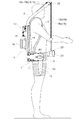
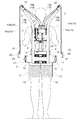
図1,2,3に示すように、作業者の背中部に取り付けられる本体部1、本体部1の上部から上方に延出された右及び左のアーム部2、本体部1の下部に備えられた右及び左の脚作用部3が備えられており、作業者への装着用の取付ベルト4、右及び左の肩ベルト5が備えられて、アシストスーツが構成されている。
[1]
First, the overall configuration of the assist suit and the
As shown in FIGS. 1, 2 and 3, the
図1,2,3に示すように、本体部1は、右及び左の縦フレーム6、右及び左の縦フレーム6の上部及び中間部に亘って連結された支持板7,8、右及び左の縦フレーム6の下部に亘って連結された横フレーム9等を備えて、枠状に構成されている。右及び左の脚作用部3に取付ベルト4が取り付けられており、右及び左の縦フレーム6に右及び左の肩ベルト5が取り付けられている。支持板8の後面に制御装置14が連結されており、制御装置14の後側を覆うように支持板8に連結された支持板15に、バッテリー16が連結されている。
As shown in FIGS. 1, 2 and 3, the
これにより、図1,2,3に示すように、右及び左の肩ベルト5に作業者の右及び左の腕部(右及び左の肩部)を入れ、取付ベルト4を作業者の腰部に巻き付けて固定することにより、作業者の背中部に本体部1が取り付けられる。
As a result, as shown in FIGS. 1, 2 and 3, the right and left arms (right and left shoulders) of the worker are inserted into the right and
図1,2,3に示すように、アシストスーツ及び荷物の重量が取付ベルト4を介して主に作業者の腰部に掛かることになるのであり、アシストスーツ及び荷物の重量が作業者の腰部により安定して支持される。右及び左の肩ベルト5は、主に本体部1が作業者の背中部から後方に離れようとする状態を止める機能を発揮する。
As shown in FIGS. 1, 2 and 3, the weight of the assist suit and the load mainly rests on the waist of the worker through the attachment belt 4, and the weight of the assist suit and the load depends on the waist of the worker It is supported stably. The right and
[2]
次に、右及び左の脚作用部3について説明する。
図1,2,3に示すように、右及び左の脚作用部3は、基部10、伝動ケース11、操作アーム12及び脚ベルト13等を備えている。横フレーム9に左右方向にスライド自在に基部10が支持されており、基部10の外端部に伝動ケース11が前向きに連結されている。
[2]
Next, the right and left
As shown in FIGS. 1, 2 and 3, the right and left
図1,2,3に示すように、伝動ケース11の前部の左右方向の横軸芯P1周りに、操作アーム12が揺動自在に支持されており、幅広のベルト状の脚ベルト13が操作アーム12の端部に連結されている。複数の平ギヤにより構成された伝動機構(図示せず)が伝動ケース11の内部に備えられ、電動モータ(図示せず)が基部10に左右方向に内装されており、電動モータにより伝動機構を介して操作アーム12が横軸芯P1周りに揺動駆動される。
As shown in FIGS. 1, 2 and 3, the
前項[1]に記載のように、作業者の背中部に本体部1を取り付ける場合において、作業者が取付ベルト4を腰部に巻き付けて固定する際、取付ベルト4と一緒に、右及び左の脚作用部3(基部10)が横フレーム9に沿って左右方向に移動可能である。
これにより、取付ベルト4の腰部への巻き付け具合により、作業者の体格に合わせるように右及び左の脚作用部3の間隔が決まるのであり、取付ベルト4により右及び左の脚作用部3の位置が決められた状態となる。
As described in the preceding paragraph [1], when attaching the
Thus, the distance between the right and left
この後、図1,2,3に示すように、作業者は脚ベルト13を太腿に巻き付けて、面ファスナ(商品面:マジックテープ(登録商標))により、脚ベルト13を太腿に固定する。以上のようにして、アシストスーツの作業者への装着が終了する。
Thereafter, as shown in FIGS. 1, 2 and 3, the operator wraps the
[3]
次に、右及び左のアーム部2について説明する。
図1,2,3に示すように、右及び左の縦フレーム6の上部が、作業者の右及び左の肩部を越えて斜め前方の斜め上方に延出されて、右及び左のアーム部2が構成されており、右及び左のアーム部2の上端部に、案内プーリー33が回転自在に支持されている。
[3]
Next, the right and left
As shown in FIGS. 1, 2 and 3, the upper portions of the right and left
図1,2,3に示すように、支持板7の後面に駆動装置17が連結されており、駆動装置17から、右の2本のワイヤ18,19及び左の2本のワイヤ18,19が延出されている。支持板7の上部に受け部材21が連結され、右及び左のアーム部2の上部に受け部材22が備えられており、ワイヤ18,19のアウター18b,19bが受け部材21,22に連結されて、ワイヤ18,19のインナー18a,19aが駆動装置17に接続されている。
As shown in FIGS. 1, 2 and 3, a
図1,2,3に示すように、右の2本のワイヤ18,19のインナー18a,19aが案内プーリー33に掛けられて下方に延出されており、右の2本のワイヤ18,19のインナー18a,19aに右のハンド部20が連結されている。左の2本のワイヤ18,19のインナー18a,19aが案内プーリー33に掛けられて下方に延出されており、左の2本のワイヤ18,19のインナー18a,19aに左のハンド部20が連結されている。
As shown in FIGS. 1, 2 and 3, the
図1,2,3に示すように、右及び左のハンド部20は、金属製の板材を断面コ字状(フック状)に折り曲げて構成されており、左右対称の形状となっている。右のハンド部20に、押しボタン型式の上昇操作スイッチ23(手動操作部に相当)が備えられており、左のハンド部20に、押しボタン型式の下降操作スイッチ24(手動操作部に相当)が備えられている。上昇及び下降操作スイッチ23,24は、ハーネス(図示せず)を介して制御装置14に接続されている。
As shown in FIGS. 1, 2, and 3, the right and
前項[1][2]に記載のように、作業者がアシストスーツを装着した状態において、作業者が右手で右のハンド部20を握るようにして持ち、左手で左のハンド部20を握るようにして持つ。
前述の状態において、作業者は右手及び左手の親指により上昇及び下降操作スイッチ23,24を押し操作する。この場合、上昇及び下降操作スイッチ23,24は復帰型に構成されており、作業者が上昇及び下降操作スイッチ23,24を押し操作していると、上昇及び下降操作スイッチ23,24から信号が出力されるのであり、作業者が上昇及び下降操作スイッチ23,24の押し操作を止めると、上昇及び下降操作スイッチ23,24の信号は停止する。
As described in the preceding paragraph [1] [2], in a state where the operator wears the assist suit, the operator holds the
In the above-mentioned state, the operator pushes and operates the raising and lowering operation switches 23 and 24 with the thumb of the right hand and the left hand. In this case, the raising and lowering operation switches 23 and 24 are configured as a return type, and when the operator presses the raising and lowering operation switches 23 and 24, the signals from the raising and lowering operation switches 23 and 24 are received. When the worker stops pressing the up and down operation switches 23, 24, the signals of the up and down operation switches 23, 24 stop.
[4]
例えば、床に置かれた荷物を高い棚やトラックの荷台に置くような場合、作業者がしゃがんで床の荷物を手で持ち、次に手を下に延ばした状態で荷物を持ちながら立ち上がり、次に手で荷物を持ち上げて、荷物を高い棚やトラックの荷台に置くような状態が想定される。
前述の状態において、上昇及び下降操作スイッチ23,24の押し操作に基づいて、制御装置14により右及び左の脚作用部3、駆動装置17が作動する状態について、説明する。
[4]
For example, when placing a load placed on the floor on a high shelf or truck bed, the operator crouchs and holds the load on the floor by hand, and then stands up with the load with the hand extended. Next, it is assumed that the load is lifted by hand and placed on a high shelf or truck bed.
In the above-described state, the state in which the right and left
図1,2,3に示すように、作業者がアシストスーツを装着した状態において、作業者が上昇及び下降操作スイッチ23,24の両方を押し操作していないと、駆動装置17は停止し、右及び左の脚作用部3の電動モータは停止状態(自由回転状態)となる。
これにより、作業者が歩行する場合や、作業者が膝部を曲げて腰部を落とす場合(しゃがむ場合)、作業者の太腿に追従するように操作アーム12が揺動するのであり、作業者の動作が妨げられることはない。
As shown in FIGS. 1, 2 and 3, when the operator wears the assist suit and the operator does not push and operate both the up and down operation switches 23 and 24, the
As a result, when the worker walks or when the worker bends the knee and lowers the waist (when crouching), the
次に、作業者がしゃがんで床の荷物を手で持つ場合、作業者が下降操作スイッチ24を押し操作すると、ワイヤ18,19のインナー18a,19aが駆動装置17から繰り出されて、右及び左のハンド部20が下降する。下降操作スイッチ24の押し操作を止めると、駆動装置17が停止して、右及び左のハンド部20が停止する。
Next, when the operator crouchs down and holds the load on the floor by hand, when the operator depresses the lowering
後述する[6]に記載のように、駆動装置17にブレーキ機能が備えられている。これにより、駆動装置17が停止した状態において、ワイヤ18,19のインナー18a,19aが駆動装置17から繰り出されることはなく、後述するように右及び左のハンド部20に荷物の重量が掛かっても、右及び左のハンド部20が下降することはない。
As described in [6] described later, the
次に、作業者は右手(左手)で右(左)のハンド部20を持ち、右及び左のハンド部20を荷物に掛けて、作業者が立ち上がることにより荷物を床から持ち上げる。この状態において作業者が上昇操作スイッチ23を押し操作すると、右及び左の脚作用部3が下方に操作され、作業者の太腿部が下方に操作されて、作業者の立ち上がりが補助される。
前述のように作業者が立ち上がる際において、前述の駆動装置17のブレーキ機能により、右及び左のハンド部20(荷物)が下降することはない。
Next, the worker holds the right (left)
As described above, when the worker stands up, the right and left hand portions 20 (packages) do not descend due to the braking function of the
前述のように、作業者が上昇操作スイッチ23を押し操作した状態で立ち上がった後、右及び左の脚作用部3が略真下に向く位置に達したことが検出されると、作業者が完全に立ち上がったと判断されて、右及び左の脚作用部3の電動モータは停止状態(自由回転状態)となる。
As described above, after the worker stands up in a state in which the operator depresses the raising
次に、駆動装置17が作動して、ワイヤ18,19のインナー18a,19aが駆動装置17に巻き取られて、右及び左のハンド部20(荷物)が上昇する。所望の位置まで右及び左のハンド部20(荷物)が上昇すると、上昇操作スイッチ23の押し操作を止めることにより、駆動装置17が停止して、右及び左のハンド部20(荷物)が停止する。
Next, the
次に、作業者は荷物を置くべき高い棚やトラックの荷台等へ歩いて移動する。作業者が高い棚やトラックの荷台等に到着すると、作業者は下降操作スイッチ24を押し操作し、右及び左のハンド部20(荷物)を下降させて、荷物を高い棚やトラックの荷台等に置いて、右及び左のハンド部20を荷物から外す。
以上のようにして、荷物を高い棚やトラックの荷台等に置くと、最初の状態に戻り、次の荷物に対して同様な操作を行う。
Next, the worker walks and moves to a high shelf, a truck bed, etc. where the luggage should be placed. When the operator arrives at a high shelf or truck bed, the operator presses the lowering
As described above, when the package is placed on a high shelf, truck bed or the like, the initial state is restored, and the same operation is performed on the next package.
[5]
次に、駆動装置17の全体構成、駆動装置17における電動モータ29及び伝動機構30について説明する。
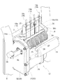
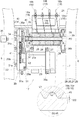
図4,5,6に示すように、駆動装置17は、左右方向の回転軸芯P2周りに回転自在に左右方向に配置された4個の回転体25,26,27,28と、4個の回転体25〜28の下側に左右方向に配置された電動モータ29と、電動モータ29の出力軸29a側の端部と回転体25〜28の左の端部(電動モータ29の出力軸29a側の端部)とに亘って上下方向に配置された伝動機構30とを備えている。
[5]
Next, the entire configuration of the
As shown in FIGS. 4, 5 and 6, the
図4,5,6に示すように、伝動機構30は、伝動ケース31と蓋部32とを備えて構成され、伝動ケース31に備えられた脚部31aが支持板7にボルト連結されている。電動モータ29の出力軸29a側の端部が伝動ケース31の下部に連結されており、電動モータ29の脚部29cか支持板7にボルト連結されている。このように、電動モータ29を伝動機構30に連結することにより、伝動機構30を介して電動モータ29が本体部1に連結された状態となっている。
As shown in FIGS. 4, 5 and 6, the
図5に示すように、伝動ケース31と蓋部32の中間部に、大径の第1ギヤ41及び小径の第2ギヤ42が一体で回転するように支持されており、電動モータ29の出力軸29aに連結された出力ギヤ29bが第1ギヤ41と咬合している。
伝動ケース31と蓋部32の上部に、伝動軸34が回転自在に支持されており、伝動軸34が伝動ケース31と蓋部32から右及び左側に突出している。伝動軸34に第3ギヤ43が固定されており、第3ギヤ43が第2ギヤ42と咬合している。
As shown in FIG. 5, a large diameter
A
図4,5,6に示すように、蓋部32にブラケット50が連結され、ブラケット50に角度センサー35(ロータリエンコーダ)が連結されており、角度センサー35が伝動軸34の左の端部に接続されている。
As shown in FIGS. 4, 5 and 6, the
[6]
次に、駆動装置17における回転体25〜28の支持構造について説明する。
図4,5,6に示すように、半円筒状の支持部材36(カバーに相当)(カバーの固定部分に相当)が備えられている。支持部材36の左の端部(電動モータ29の出力軸29a側の端部)に、半円状のフランジ部36a(第1軸受け部に相当)が備えられて、フランジ部36aが伝動ケース31の上部に連結されている。これにより、支持部材36のフランジ部36aが、伝動ケース31(伝動機構30)を介して支持板7(本体部1)に連結された状態となっている。
[6]
Next, the support structure of the rotating bodies 25-28 in the
As shown in FIGS. 4, 5 and 6, a semi-cylindrical support member 36 (corresponding to a cover) (corresponding to a fixed portion of the cover) is provided. A
図4,5,6に示すように、支持部材36の右の端部(電動モータ29の出力軸29a側の反対側の端部)に、脚部36b(第2軸受け部に相当)が備えられており、脚部36bが支持板7(本体部1)にボルト連結されている。
As shown in FIGS. 4, 5 and 6, a
図5及び図6に示すように、支持部材36のフランジ部36aに、ベアリング37が支持され、支持部材36の脚部36bにベアリング38が支持されている。断面四角状の駆動軸39がベアリング37,38により回転軸芯P2周りに回転自在に支持されており、駆動軸39と伝動軸34とが円筒状の連結部材40により連結されている。
As shown in FIGS. 5 and 6, the
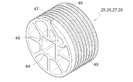
図6及び図8に示すように、回転体25〜28は合成樹脂により円柱状に構成されて、中央部に断面四角状の取付孔44が開口されており、取付孔44に駆動軸39が挿入されることにより、回転体25〜28が駆動軸39に取り付けられている。
As shown in FIG. 6 and FIG. 8, the rotating
図4及び図6に示すように、透明の合成樹脂製で半円筒状のカバー部材45(カバーに相当)(カバーの着脱部分に相当)が備えられており、カバー部材45が、支持部材36のフランジ部36a及び脚部35bにボルト連結されている。カバー部材45によりベアリング37,38が固定されているのであり、支持部材36及びカバー部材45により回転体25〜28の外周面が覆われている。
As shown in FIGS. 4 and 6, a semi-cylindrical cover member 45 (corresponding to a cover) (corresponding to an attachment / detachment portion of the cover) made of transparent synthetic resin is provided, and the
これにより、回転体25〜28(駆動軸39)の左の端部(電動モータ29の出力軸29a側の端部)が、ベアリング37を介して支持部材36のフランジ部36aに支持された状態となっている。回転体25〜28(駆動軸39)の右の端部(電動モータ29の出力軸29a側の反対側の端部)が、ベアリング38を介して支持部材36の脚部36bに支持された状態となっている。
Thereby, the state in which the left end (end on the
以上の構造により、電動モータ29の動力が伝動機構30(第1,2,3ギヤ41,42,43)を介して、駆動軸39に伝達されて、回転体25〜28(駆動軸39)が巻き取り側及び繰り出し側に回転駆動される。
電動モータ29に電磁ブレーキ(図示せず)が備えられている。電動モータ29の作動時に電磁ブレーキは解除状態となり、電動モータ29の停止時及び非通電時に電磁ブレーキは制動状態となる。
With the above structure, the power of the
The
図4及び図6に示すように、カバー部材45を支持部材36から取り外すことにより、ベアリング37,38を支持部材36のフランジ部36a及び脚部36bから取り外すことができ、駆動軸39を連結部材40から抜き出すことにより、回転体25〜28及び駆動軸39を取り外すことができる。このように回転体25〜28及び駆動軸39を取り外すことにより、駆動軸39から回転体25〜28を抜き出して、回転体25〜28の交換を行うことができる。
As shown in FIGS. 4 and 6, by removing the
[7]
次に、駆動装置17における回転体25〜28について説明する。
図8及び図9に示すように、回転体25〜28は合成樹脂により円柱状に構成されて、中央部に断面四角状の取付孔44が開口されている。回転体25〜28の右の横側面に、ワイヤ18,19のインナー18a,19aの取付部46が備えられており、回転体25〜28の外周面の右の部分において、取付部46につながる溝部47が備えられている。
[7]
Next, the rotating
As shown in FIGS. 8 and 9, the
図8及び図9に示すように、回転体25〜28の外周面における回転軸芯P2の方向での左の部分48において、回転体25〜28の外周面を複数周に亘って螺旋状(雄ネジ状)に回りながら、回転体25〜28の溝部47と左の部分48とに亘って接続される連続した1本の溝部49が、回転体25〜28の外周面に備えられている。
As shown in FIGS. 8 and 9, in the
図7及び図10に示すように、ワイヤ18,19のアウター18b,19bの端部18c,19cが、受け部材21に連結されており、4個の回転体25〜28に対向するように4個の開口部36cが支持部材36に備えられている。
As shown in FIGS. 7 and 10, the
図4及び図7に示すように、左のワイヤ18のインナー18aが、支持部材36の回転体25に対抗する開口部36cを通っており、左のワイヤ18のインナー18aの端部が回転体25の取付部46に取り付けられている。左のワイヤ19のインナー19aが、支持部材36の回転体26に対向する開口部36cを通っており、左のワイヤ19のインナー19aの端部が回転体26の取付部46に取り付けられている。
As shown in FIGS. 4 and 7, the inner 18a of the
図4及び図7に示すように、右のワイヤ18のインナー18aが、支持部材36の回転体28に対向する開口部36cを通っており、右のワイヤ18のインナー18aの端部が回転体28の取付部46に取り付けられている。右のワイヤ19のインナー19aが、支持部材36の回転体27に対向する開口部36cを通っており、右のワイヤ19のインナー19aの端部が回転体27の取付部46に取り付けられている。
As shown in FIGS. 4 and 7, the inner 18 a of the
[8]
次に、駆動装置17における回転体25〜28において、ワイヤ18,19のインナー18a,19aの巻き取りの状態について説明する。
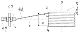
図10に示すように、ワイヤ18,19のアウター18b,19bの端部18c,19cが、回転体25〜28の外周面に対向する位置で、且つ、回転体25〜28の外周面における溝部49の回転軸芯P2方向での範囲Wの中央部に対向する位置W1に配置されている。
[8]
Next, in the
As shown in FIG. 10, groove portions in the outer peripheral surface of the rotating bodies 25-28 at a position where the
図10に示す状態は、ワイヤ18,19のインナー18a,19aが回転体25〜28から完全に繰り出された状態であり、ワイヤ18,19のインナー18a,19aが回転体25〜28の溝部47に位置して、溝部49に入っていない状態である。
In the state shown in FIG. 10, the
図10に示す状態において背面視で、ワイヤ18,19のインナー18a,19aが、ワイヤ18,19のアウター18b,19bの端部18c,19cから、回転体25〜28の溝部47に向く状態となっている。回転体25〜28と受け部材21との間隔が比較的大きなものに設定されているので、ワイヤ18,19のインナー18a,19aが回転体25〜28の溝部47に向く角度θ1は小さなものとなっている。
In a state shown in FIG. 10, the inner 18a, 19a of the
図10に示す状態から回転体25〜28が巻き取り側に回転駆動されると(図7の紙面反時計方向)、ワイヤ18,19のインナー18a,19aが回転体25〜28の溝部47から溝部49に順に入っていき、ワイヤ18,19のインナー18a,19aが回転体25〜28の溝部49に沿って回転体25〜28の外周面に螺旋状に巻き付けられる状態となって、ワイヤ18,19のインナー18a,19aが回転体25〜28に巻き取られる。
When the
これにより、図10から図11に示すように、背面視で、ワイヤ18,19のインナー18a,19aが、回転体25〜28の溝部47に向いた状態から、範囲Wの中央部に対向する位置W1に接近していく。
Thereby, as shown in FIGS. 10 to 11, the
この場合、ワイヤ18,19のインナー18a,19aが回転体25〜28の溝部47から溝部49に順に入っていくのであり、ワイヤ18,19のインナー18a,19aの次の部分が、ワイヤ18,19のインナー18a,19aの最初の部分の上側に巻き取られるという状態(ワイヤ18,19のインナー18a,19aが二重に重ねて巻き取られる状態)は生じない。
In this case, the
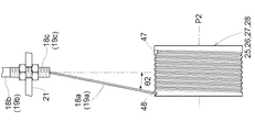
図11に示す状態からさらに回転体25〜28が巻き取り側に回転駆動されると(図7の紙面反時計方向)、ワイヤ18,19のインナー18a,19aが回転体25〜28の溝部47から溝部49に順に入っていき、図11から図12に示すように、背面視で、ワイヤ18,19のインナー18a,19aが、範囲Wの中央部に対向する位置W1を通過して、回転体25〜28の左の部分48に向く状態となる。
When the
図12に示す状態において、回転体25〜28と受け部材21との間隔が比較的大きなものに設定されているので、ワイヤ18,19のインナー18a,19aが回転体25〜28の左の部分48に向く角度θ2は小さなものとなっている。
In the state shown in FIG. 12, since the distance between the rotating bodies 25-28 and the receiving
図12に示すように、ワイヤ18,19のインナー18a,19aが回転体25〜28の左の部分48に達するまで、回転体25〜28が巻き取り側に回転駆動されると、ワイヤ18,19のインナー18a,19aが回転体25〜28の溝部49の全ての部分に入った状態となるので、これ以上に、回転体25〜28を巻き取り側に回転駆動することはできない。
これにより、ワイヤ18,19のインナー18a,19aが回転体25〜28の左の部分48に達するまで、回転体25〜28が回転したことが角度センサー35により検出されると、電動モータ29が自動的に停止する。
As shown in FIG. 12, when the
Thus, when the
[9]
次に、駆動装置17における回転体25〜28において、ワイヤ18,19のインナー18a,19aの繰り出しの状態について説明する。
図12に示すように、ワイヤ18,19のインナー18a,19aが回転体25〜28の左の部分48に達するまで、回転体25〜28が巻き取り側に回転駆動された状態において、回転体25〜28が繰り出し側に回転駆動されると(図7の紙面時計方向)、ワイヤ18,19のインナー18a,19aが回転体25〜28の溝部49(回転体25〜28の左の部分48)から順に出ていき、ワイヤ18,19のインナー18a,19aが回転体25〜28から繰り出される。
[9]
Next, in the
As shown in FIG. 12, the
これにより、図12から図11に示すように、背面視で、ワイヤ18,19のインナー18a,19aが、回転体25〜28の左の部分48に向いた状態から、範囲Wの中央部に対向する位置W1に接近していく。
Thereby, as shown in FIG. 12 to FIG. 11, in a rear view, the
図11に示す状態からさらに回転体25〜28が繰り出し側に回転駆動されると(図7の紙面時計方向)、ワイヤ18,19のインナー18a,19aが回転体25〜28の溝部49から順に出ていき、図12から図11に示すように、背面視で、ワイヤ18,19のインナー18a,19aが、範囲Wの中央部に対向する位置W1を通過して、回転体25〜28の溝部47に向く状態となる。
When the
図10に示すように、ワイヤ18,19のインナー18a,19aが回転体25〜28の溝部47に達するまで、回転体25〜28が繰り出し側に回転駆動されると、ワイヤ18,19のインナー18a,19aが回転体25〜28の溝部49の全ての部分から出た状態となるので、これ以上に、回転体25〜28を繰り出し側に回転駆動することはできない。
これにより、ワイヤ18,19のインナー18a,19aが回転体25〜28の溝部47に達するまで、回転体25〜28が回転したことが角度センサー35により検出されると、電動モータ29が自動的に停止する。
As shown in FIG. 10, when the
As a result, when the
例えば図11に示すような途中の状態で電動モータ29が停止した後、回転体25〜28が巻き取り側に回転駆動されると、前項[8]の記載と同様に、ワイヤ18,19のインナー18a,19aが回転体25〜28の溝部49に順に入っていき、ワイヤ18,19のインナー18a,19aが回転体25〜28の溝部49に沿って回転体25〜28の外周面に螺旋状に巻き付けられる。
For example, after the
同様に図11に示すような途中の状態で電動モータ29が停止した後、回転体25〜28が繰り出し側に回転駆動されると、本項[9]の記載と同様に、ワイヤ18,19のインナー18a,19aが回転体25〜28の溝部49から順に出ていき、ワイヤ18,19のインナー18a,19aが回転体25〜28から繰り出される。
Similarly, after the
[10]
次に、駆動装置17における回転体25〜28と支持部材36及びカバー部材45との関係について説明する。
図4及び図7に示すように、支持部材36及びカバー部材45の内面は円筒状となっており、支持部材36及びカバー部材45の内面が回転体25〜28の外周面に接近した状態となっている。
[10]
Next, the relationship between the
As shown in FIGS. 4 and 7, the inner surfaces of the
図5に示すように、ワイヤ18,19のインナー18a,19aの外径D1に対して、回転体25〜28の溝部49の深さが、ワイヤ18,19のインナー18a,19aの外径D1よりも十分に大きなものとなっている。
これにより、ワイヤ18,19のインナー18a,19aが回転体25〜28の溝部49に入った状態で、ワイヤ18,19のインナー18a,19aが回転体25〜28の溝部49に埋没した状態となる。
As shown in FIG. 5, with respect to the outer diameter D1 of the
Thus, with the
回転体25〜28の外周面と支持部材36及びカバー部材45の内面との間隔W2が、ワイヤ18,19のインナー18a,19aの外径D1よりも小さなものに設定されている。
これにより、図5に示すように、ワイヤ18,19のインナー18a,19aが回転体25〜28の溝部49に入った状態において、支持部材36及びカバー部材45の内面がワイヤ18,19のインナー18a,19aに接触することはない。
The distance W2 between the outer peripheral surface of the rotary members 25-28 and the inner surface of the
Thereby, as shown in FIG. 5, the inner surfaces of the
図5に示すように、回転体25〜28の溝部49に入っていたワイヤ18,19のインナー18a,19aが回転体25〜28の溝部49から出ようとしても、ワイヤ18,19のインナー18a,19aが回転体25〜28の溝部49から完全に出るまでに、ワイヤ18,19のインナー18a,19aが支持部材36及びカバー部材45の内面に接触するのであり、これによって回転体25〜28の溝部49に入っていたワイヤ18,19のインナー18a,19aが回転体25〜28の溝部49から出る状態が抑えられる。
As shown in FIG. 5, even if the
[発明の実施の第1別形態]
図4,5,6に示す構造に対して、以下に示すように構成してもよい。
4個の回転体25〜28の下側に、電動モータ29の出力軸29aが右に向くように、電動モータ29を左右方向に配置して、電動モータ29の出力軸29a側の端部と回転体25〜28の右の端部(電動モータ29の出力軸29a側の端部)とに亘って、上下方向に伝動機構30を備える。
前述のように構成すると、支持部材36の右の端部にフランジ部36aが備えられ、支持部材36の左の端部に脚部36bが備えられる。
[First alternative embodiment of the invention]
The structures shown in FIGS. 4, 5 and 6 may be configured as follows.
The
When configured as described above, the right end of the
[発明の実施の第2別形態]
前述の[発明を実施するための形態][発明の実施の第1別形態]において、電動モータ29の脚部29cを廃止して、電動モータ29が伝動機構30を介してのみ支持板7(本体部1)に連結されるように構成してもよい。
Second Embodiment of the Invention
In the above-mentioned [Aspects for Carrying Out the Invention] [First Embodiment of the Invention], the
支持部材36のフランジ部36aにベアリング37を支持するのではなく、伝動ケース31(伝動機構30)にベアリング37を支持させるように構成してもよい。このように構成すると、伝動ケース31が第1軸受け部となる。
Instead of supporting the bearing 37 on the
[発明の実施の第3別形態]
図1,2,3に示す右のハンド部20に対して、1本のワイヤ18及び1個の回転体25を備え、左のハンド部20に対して、1本のワイヤ18及び1個の回転体28を備えるように構成してもよい。
[Third Embodiment of the Invention]
For the
[発明の実施の第4別形態]
図5に示す構造に対して、以下に示すように構成してもよい。
図13に示すように、ワイヤ18,19のインナー18a,19aの外径D1に対して回転体25〜28の溝部49の深さを、ワイヤ18,19のインナー18a,19aの外径D1の約1/2に設定する。
Fourth Alternative Embodiment of the Invention
The structure shown in FIG. 5 may be configured as follows.
As shown in FIG. 13, with respect to the outer diameter D1 of the
これにより、ワイヤ18,19のインナー18a,19aが回転体25〜28の溝部49に入った状態で、ワイヤ18,19のインナー18a,19aが回転体25〜28の溝部49から少し露出する状態となる。
回転体25〜28の外周面と支持部材36及びカバー部材45の内面との間隔W2を、ワイヤ18,19のインナー18a,19aの外径D1よりも小さく、且つワイヤ18,19のインナー18a,19aの外径D1の1/2よりも大きなものに設定する。
Thus, with the
The distance W2 between the outer peripheral surface of the rotary members 25-28 and the inner surface of the
[発明の実施の第5別形態]
前述の[発明を実施するための形態][発明の実施の第1別形態]〜[発明の実施の第4別形態]において、右及び左のアーム部2を廃止して、1本のアーム部2を備えてもよい。
前述のように構成した場合、1本のアーム部2から2本のワイヤ18を延出して、2本のワイヤ18の一方に右のハンド部20を備え、2本のワイヤ18の他方に左のハンド部20を備える。
又は、1本のアーム部2から1本のワイヤ18を延出し、1本のワイヤ18の端部を二股状に分岐させて、分岐部分の一方に右のハンド部20を備え、分岐部分の他方に左のハンド部20を備える。
[Fifth alternative embodiment of the invention]
In the above-described [Aspects for Carrying Out the Invention] [First Embodiment of the Invention] to [Fourth Embodiment of the Invention], the right and left
When configured as described above, two
Alternatively, one
[発明の実施の第6別形態]
前述の[発明を実施するための形態][発明の実施の第1別形態]〜[発明の実施の第5別形態]において、右及び左の脚作用部3を備えないように構成してもよい。バッテリー16を、支持板15ではなく横フレーム9の後面に連結するように構成してもよい。
Sixth Embodiment of the Invention
In the aforementioned [First Embodiment of the Invention] to [Fifth Embodiment of the Invention], the right and left
本発明は、作業者が装着して使用するもので、作業者の作業(動作)を動力によって補助するアシストスーツに適用できる。 The present invention can be applied to an assist suit which is worn and used by a worker and which assists the worker's work (motion) by power.
1 本体部
2 アーム部
17 駆動装置
18,19 ワイヤ
20 ハンド部
23,24 手動操作部
25,26,27,28 回転体
29 電動モータ
29a 電動モータの出力軸
30 伝動機構
36 カバー、固定部分
36a 第1軸受け部
36b 第2軸受け部
36c 固定部分の開口部
40 連結部材
45 カバー、着脱部分
P2 回転軸芯
DESCRIPTION OF
Claims (7)
前記アーム部から下方に延出されたワイヤと、作業者が手で持つことにより荷物を保持するもので前記ワイヤに連結されたハンド部とが備えられ、
前記ワイヤを巻き取ることにより前記ハンド部を上昇させ、前記ワイヤを繰り出すことにより前記ハンド部を下降させる駆動装置と、
作業者に操作されることにより前記駆動装置を作動させる手動操作部とが備えられており、
前記駆動装置を前記本体部に備えて、
前記駆動装置が、左右方向の回転軸芯周りに回転自在に左右方向に配置されて前記ワイヤを巻き取り及び繰り出す回転体と、前記回転体の下側に左右方向に配置された電動モータと、前記電動モータの出力軸側の端部と前記回転体の右又は左の前記出力軸側の端部とに亘って上下方向に配置された伝動機構とを備えており、
前記電動モータの動力が前記伝動機構を介して前記回転体に伝達されて、前記回転体が巻き取り側及び繰り出し側に回転駆動されるように構成しており、
前記本体部は、右及び左のフレームと、右及び左の前記フレームの上部に亘って連結された上部部材とを備え、前記回転体が前記上部部材に支持されているアシストスーツ。 A main body attached to the back of the worker, and an arm extending forward from the main body beyond the worker;
A wire extending downward from the arm portion, and a hand portion that holds a load by holding by the operator with a hand and is connected to the wire are provided.
A driving device that raises the hand unit by winding the wire and lowers the hand unit by unwinding the wire;
A manual operation unit for operating the drive unit by being operated by an operator;
The drive unit is provided to the main body,
A rotating body disposed in the lateral direction so as to freely rotate the wire around the rotational axis center of the lateral direction, and an electric motor disposed in the lateral direction below the rotating body; And a transmission mechanism vertically disposed across the output shaft side end of the electric motor and the right or left output shaft side end of the rotating body.
The power of the electric motor is transmitted to the rotating body via the transmission mechanism, and the rotating body is rotationally driven to the winding side and the unwinding side ,
The said main-body part is an assist suit by which the upper member connected over the upper part of the flame | frame of the right and the left and the right and the left was connected, and the said rotary body is supported by the said upper member .
前記本体部は、右及び左のフレームの前記フレームの中間部に亘って連結された中間部板部材を更に備えている請求項1に記載のアシストスーツ。 The assist suit according to claim 1, wherein the body further comprises an intermediate plate member connected across an intermediate portion of the right and left frames.
前記回転体の右又は左の前記出力軸側の反対側の端部を支持する第2軸受け部を備え、前記第2軸受け部を前記本体部に連結して、
前記第1及び第2軸受け部により、前記回転体を前記回転軸芯周りに回転自在に支持している請求項1又は2に記載のアシストスーツ。 The transmission mechanism is provided with a first bearing portion for supporting the right or left end portion on the output shaft side of the rotating body, and the transmission mechanism is coupled to the main body portion;
A second bearing portion for supporting an end portion on the opposite side to the right or left output shaft side of the rotating body, and the second bearing portion is coupled to the main body portion;
The first and the second bearing portion, the assist suit according to the rotating body to the rotational axis claim 1 or 2 rotatably supported and a core around.
前記固定部分に開口部を備えて、前記ワイヤが前記開口部を通って前記回転体に巻き取り及び繰り出される請求項5に記載のアシストスーツ。 The cover includes a fixed portion and a detachable detachable portion.
The assist suit according to claim 5 , wherein the fixed portion is provided with an opening, and the wire is wound around and fed out to the rotating body through the opening.
前記着脱部分を取り外した状態で、前記回転体を前記伝動機構から取り外し自在に構成している請求項6に記載のアシストスーツ。 Connecting the rotating body and the transmission mechanism via a connecting and disconnecting connecting member;
The assist suit according to claim 6 , wherein the rotating body is configured to be removable from the transmission mechanism in a state in which the detachable portion is removed.
Priority Applications (5)
| Application Number | Priority Date | Filing Date | Title |
|---|---|---|---|
| JP2015227688A JP6541553B2 (en) | 2015-11-20 | 2015-11-20 | Assist suit |
| PCT/JP2016/084072 WO2017086378A1 (en) | 2015-11-20 | 2016-11-17 | Assistance suit |
| CN201680063412.7A CN108136591B (en) | 2015-11-20 | 2016-11-17 | Auxiliary clothes |
| EP16866379.7A EP3378606B1 (en) | 2015-11-20 | 2016-11-17 | Assistance suit |
| KR1020187011365A KR102062998B1 (en) | 2015-11-20 | 2016-11-17 | Assist suit |
Applications Claiming Priority (1)
| Application Number | Priority Date | Filing Date | Title |
|---|---|---|---|
| JP2015227688A JP6541553B2 (en) | 2015-11-20 | 2015-11-20 | Assist suit |
Publications (2)
| Publication Number | Publication Date |
|---|---|
| JP2017094422A JP2017094422A (en) | 2017-06-01 |
| JP6541553B2 true JP6541553B2 (en) | 2019-07-10 |
Family
ID=58803457
Family Applications (1)
| Application Number | Title | Priority Date | Filing Date |
|---|---|---|---|
| JP2015227688A Active JP6541553B2 (en) | 2015-11-20 | 2015-11-20 | Assist suit |
Country Status (1)
| Country | Link |
|---|---|
| JP (1) | JP6541553B2 (en) |
Family Cites Families (8)
| Publication number | Priority date | Publication date | Assignee | Title |
|---|---|---|---|---|
| JP3024978U (en) * | 1995-10-13 | 1996-06-07 | 吉村 敏正 | Backpack-type luggage lifting device |
| KR0152874B1 (en) * | 1995-11-30 | 1998-10-15 | 이종수 | Deposit/take-out apparatus for automatic warehouse |
| EP2556009B1 (en) * | 2010-04-09 | 2016-02-10 | Ekso Bionics | Exoskeleton load handling system and method of use |
| CN103038152A (en) * | 2010-04-09 | 2013-04-10 | 洛克希德马丁公司 | Portable load lifting system |
| JP5909063B2 (en) * | 2011-09-06 | 2016-04-26 | 国立大学法人 和歌山大学 | Power assist robot |
| WO2014006850A1 (en) * | 2012-07-05 | 2014-01-09 | パナソニック株式会社 | Support device, operation support device, and muscle strength training support device |
| WO2015132850A1 (en) * | 2014-03-03 | 2015-09-11 | 三菱電機株式会社 | Hoist for elevator |
| JP6148192B2 (en) * | 2014-03-20 | 2017-06-14 | 株式会社クボタ | Assist suit |
-
2015
- 2015-11-20 JP JP2015227688A patent/JP6541553B2/en active Active
Also Published As
| Publication number | Publication date |
|---|---|
| JP2017094422A (en) | 2017-06-01 |
Similar Documents
| Publication | Publication Date | Title |
|---|---|---|
| CN108430714B (en) | assistive device | |
| JP6660827B2 (en) | Assist equipment | |
| CN109937123A (en) | Ancillary equipment | |
| JP2018002343A (en) | Assist tool | |
| JP6541553B2 (en) | Assist suit | |
| JP6541552B2 (en) | Assist suit | |
| JP6624940B2 (en) | Assist equipment | |
| JP6581962B2 (en) | Assist equipment | |
| JP6785744B2 (en) | Assist equipment | |
| JP6905842B2 (en) | Hand part for holding luggage | |
| JP6581961B2 (en) | Assist equipment | |
| EP3647255A1 (en) | Hand part for holding baggage, and assistance implement | |
| JP6671179B2 (en) | Assist equipment | |
| JP2019026470A (en) | Assist appliance | |
| JP2018158407A (en) | Hand part for holding luggage | |
| JP6671180B2 (en) | Assist equipment | |
| JP6833665B2 (en) | Assist equipment | |
| JP6854732B2 (en) | Hand part for holding luggage | |
| JP6833633B2 (en) | Assist equipment | |
| JP2019011152A (en) | Assist equipment | |
| JP6905891B2 (en) | Hand part for holding luggage | |
| JP2020093356A (en) | Assist equipment | |
| JP6804354B2 (en) | Hand part for holding luggage | |
| JP6624941B2 (en) | Assist equipment | |
| JP6843017B2 (en) | Hand part for holding luggage |
Legal Events
| Date | Code | Title | Description |
|---|---|---|---|
| A621 | Written request for application examination |
Free format text: JAPANESE INTERMEDIATE CODE: A621 Effective date: 20171222 |
|
| A131 | Notification of reasons for refusal |
Free format text: JAPANESE INTERMEDIATE CODE: A131 Effective date: 20181023 |
|
| A521 | Written amendment |
Free format text: JAPANESE INTERMEDIATE CODE: A523 Effective date: 20181221 |
|
| TRDD | Decision of grant or rejection written | ||
| A01 | Written decision to grant a patent or to grant a registration (utility model) |
Free format text: JAPANESE INTERMEDIATE CODE: A01 Effective date: 20190514 |
|
| A61 | First payment of annual fees (during grant procedure) |
Free format text: JAPANESE INTERMEDIATE CODE: A61 Effective date: 20190611 |
|
| R150 | Certificate of patent or registration of utility model |
Ref document number: 6541553 Country of ref document: JP Free format text: JAPANESE INTERMEDIATE CODE: R150 |