JP6538430B2 - Vibration information display device for machine tools - Google Patents
Vibration information display device for machine tools Download PDFInfo
- Publication number
- JP6538430B2 JP6538430B2 JP2015110351A JP2015110351A JP6538430B2 JP 6538430 B2 JP6538430 B2 JP 6538430B2 JP 2015110351 A JP2015110351 A JP 2015110351A JP 2015110351 A JP2015110351 A JP 2015110351A JP 6538430 B2 JP6538430 B2 JP 6538430B2
- Authority
- JP
- Japan
- Prior art keywords
- vibration
- information
- monitor
- tool
- chatter
- Prior art date
- Legal status (The legal status is an assumption and is not a legal conclusion. Google has not performed a legal analysis and makes no representation as to the accuracy of the status listed.)
- Active
Links
Images


Classifications
-
- B—PERFORMING OPERATIONS; TRANSPORTING
- B23—MACHINE TOOLS; METAL-WORKING NOT OTHERWISE PROVIDED FOR
- B23Q—DETAILS, COMPONENTS, OR ACCESSORIES FOR MACHINE TOOLS, e.g. ARRANGEMENTS FOR COPYING OR CONTROLLING; MACHINE TOOLS IN GENERAL CHARACTERISED BY THE CONSTRUCTION OF PARTICULAR DETAILS OR COMPONENTS; COMBINATIONS OR ASSOCIATIONS OF METAL-WORKING MACHINES, NOT DIRECTED TO A PARTICULAR RESULT
- B23Q15/00—Automatic control or regulation of feed movement, cutting velocity or position of tool or work
- B23Q15/007—Automatic control or regulation of feed movement, cutting velocity or position of tool or work while the tool acts upon the workpiece
- B23Q15/12—Adaptive control, i.e. adjusting itself to have a performance which is optimum according to a preassigned criterion
-
- G—PHYSICS
- G05—CONTROLLING; REGULATING
- G05B—CONTROL OR REGULATING SYSTEMS IN GENERAL; FUNCTIONAL ELEMENTS OF SUCH SYSTEMS; MONITORING OR TESTING ARRANGEMENTS FOR SUCH SYSTEMS OR ELEMENTS
- G05B19/00—Programme-control systems
- G05B19/02—Programme-control systems electric
- G05B19/18—Numerical control [NC], i.e. automatically operating machines, in particular machine tools, e.g. in a manufacturing environment, so as to execute positioning, movement or co-ordinated operations by means of programme data in numerical form
- G05B19/404—Numerical control [NC], i.e. automatically operating machines, in particular machine tools, e.g. in a manufacturing environment, so as to execute positioning, movement or co-ordinated operations by means of programme data in numerical form characterised by control arrangements for compensation, e.g. for backlash, overshoot, tool offset, tool wear, temperature, machine construction errors, load, inertia
-
- G—PHYSICS
- G05—CONTROLLING; REGULATING
- G05B—CONTROL OR REGULATING SYSTEMS IN GENERAL; FUNCTIONAL ELEMENTS OF SUCH SYSTEMS; MONITORING OR TESTING ARRANGEMENTS FOR SUCH SYSTEMS OR ELEMENTS
- G05B2219/00—Program-control systems
- G05B2219/30—Nc systems
- G05B2219/37—Measurements
- G05B2219/37081—Display machining parameters
-
- G—PHYSICS
- G05—CONTROLLING; REGULATING
- G05B—CONTROL OR REGULATING SYSTEMS IN GENERAL; FUNCTIONAL ELEMENTS OF SUCH SYSTEMS; MONITORING OR TESTING ARRANGEMENTS FOR SUCH SYSTEMS OR ELEMENTS
- G05B2219/00—Program-control systems
- G05B2219/30—Nc systems
- G05B2219/41—Servomotor, servo controller till figures
- G05B2219/41256—Chattering control
-
- Y—GENERAL TAGGING OF NEW TECHNOLOGICAL DEVELOPMENTS; GENERAL TAGGING OF CROSS-SECTIONAL TECHNOLOGIES SPANNING OVER SEVERAL SECTIONS OF THE IPC; TECHNICAL SUBJECTS COVERED BY FORMER USPC CROSS-REFERENCE ART COLLECTIONS [XRACs] AND DIGESTS
- Y02—TECHNOLOGIES OR APPLICATIONS FOR MITIGATION OR ADAPTATION AGAINST CLIMATE CHANGE
- Y02P—CLIMATE CHANGE MITIGATION TECHNOLOGIES IN THE PRODUCTION OR PROCESSING OF GOODS
- Y02P90/00—Enabling technologies with a potential contribution to greenhouse gas [GHG] emissions mitigation
- Y02P90/02—Total factory control, e.g. smart factories, flexible manufacturing systems [FMS] or integrated manufacturing systems [IMS]
Description
本発明は、工具又はワークを回転させながら加工を行う工作機械において、加工面及び工具寿命を悪化させる一因であるびびり振動に係る情報を表示するための振動情報表示装置に関するものである。 The present invention relates to a vibration information display device for displaying information related to chattering vibration which is a cause of deterioration of a machining surface and a tool life in a machine tool which performs machining while rotating a tool or a work.
機械加工において、主軸回転速度や送り速度などの加工条件によっては、びびり振動が生じ加工面が悪化することがある。また、びびり振動によって工具がダメージを受け、工具寿命の悪化にもつながる。初品の加工条件は、過去の実績に基づいて仮設定され、オペレータは、仮設定した加工状況を確認しながら最終的な加工条件を決定する。しかし、生産準備に必要とするコストを削減するために、金型のような加工時間が長くなるものではオペレータが付き添って加工確認を行わないケースもある。このように無人で機械を稼働させる場合、特許文献1のような技術を利用し、主軸速度を自動的に変えることで生じたびびりを抑制することができる。
ところで、加工中に生じた振動や、上記のような主軸速度を自動的に変える動作の有無などの稼働状況を記録・分析し通知する技術として、例えば特許文献2〜4が知られている。特許文献2では、回転機械の回転駆動により振動が発生する複数箇所に設置する複数の振動検出センサと、前記振動検出センサと接続した監視診断装置と、前記監視診断装置と接続し、該監視診断装置で異常診断がなされた時に警報を出力する警報通知手段とを備えている。警報値振動レベルを、管理者に電子メールまたは前記警報通知手段を構成する操作端末画面にメッセージ表示している。
特許文献3には、工作機械の近傍に、または、工作機械と一体的に設けられたNC装置において、工作機械の稼働情報と時刻情報とを合わせて1つのログデータとし、1日分の前記ログデータを記憶装置内に1日毎のログファイルとして記録し、ログファイル内のログデータを集計し、集計結果を記憶装置内に実績情報ファイルとして記録し、ログファイルおよび実績情報ファイルのデータを表示手段に表示する技術が示されている。また、ログデータは、日付、時間のデータ、工具番号、コメント、主軸の回転速度、送り速度、使用時間(例えば、工具交換指令から次工具交換指令までの時間:秒)、切削時間(例えば、G01,G02,G03等の送り指令が実行されている時間:秒)、早送り時間(例えば、G00等の早送り指令が実行されている時間:秒)等のデータを有することが示されている。
特許文献4には、回転軸の回転速度及び周波数領域の振動加速度を稼働履歴として記憶するとともに、当該稼働履歴を、回転軸の回転速度が変化した場合のみならず、周波数領域の振動加速度の最大値が所定の閾値を超えた場合にも記憶する稼働履歴管理装置が示されている。回転軸の回転速度の変化とびびり振動の発生状況とを関連づけて記憶することができるため、作業者は回転軸の回転速度とびびり振動の発生状況とを関連づけて把握し、びびり振動を効果的に抑制する手助けとしている。
なお、記憶されている稼働履歴を利用して、たとえば非特許文献1「2008年精密工学会春季大会学術講演会講演論文集『エンドミル加工における実験結果を利用した伝達関数の逆同定』」等に記載されているような公知の方法を採用し、安定限界線図を表示することも知られている。
In machining, chatter vibration may occur depending on processing conditions such as the spindle rotational speed and the feed rate, and the processed surface may be deteriorated. In addition, chatter vibration damages the tool and leads to deterioration of tool life. The processing conditions of the first product are temporarily set based on the past results, and the operator determines the final processing conditions while confirming the temporarily set processing status. However, in order to reduce the cost required for preparation for production, there are cases in which the operator does not carry out processing confirmation when the processing time such as a mold is long. As described above, when the machine is operated unattended, it is possible to suppress the occurrence of chattering by automatically changing the spindle speed using the technology as disclosed in
By the way, patent documents 2-4 are known as a technique which records and analyzes operating conditions, such as the presence or absence of the operation | movement which changes the above-mentioned spindle speed automatically, for example, to the vibration which arose during processing. In
According to
In
In addition, for example, in Non-Patent
特許文献2の発明は、異常診断がなされた時に警報を警報通知手段に出力し、その際の振動レベルを、管理者に電子メールまたは前記警報通知手段を構成する操作端末画面に表示する。しかしながら、工具とワークを相対的に移動させて加工する工作機械においては、ワークのどの位置で異常だったのかを明らかにしてプログラムを修正する必要がある。したがって回転機械設備と異なり、異常が生じた位置情報も必要となるため、情報不足となる。
特許文献3の発明は、1日分の稼働情報をログファイルとして記録しており、ファイル内のデータを表示することができるが、さまざまな稼働情報の中から加工異常に関する情報を抽出する必要があり、稼働情報分析に時間がかかるという課題がある。また、オペレータが加工に立ち会っていない場合は、稼働情報を見るまでびびり振動が生じたのかは明らかにならない。
特許文献4の発明は、記録した稼働情報を用いて安定限界線図などのびびり振動の対策を提示できるが、特許文献2と同様にオペレータが加工に立ち会っていない場合は、稼働情報を見るまでびびり振動が生じたのかは明らかにならないという課題がある。
The invention of
The invention of
The invention of
そこで、本発明は、びびり振動の情報を瞬時にモニタに表示することで、機械を離れていたオペレータにいち早く提示して加工異常を稼働情報と共に知らせることができる工作機械の振動情報表示装置を提供することを目的とする。 Therefore, the present invention provides a vibration information display device for a machine tool capable of quickly presenting to an operator who has left the machine and notifying processing abnormality together with operation information by instantaneously displaying chatter vibration information on a monitor. The purpose is to
上記目的を達成するために、請求項1に記載の発明は、工具又はワークを回転させて前記ワークの加工を行うと共に、当該加工の際に生じるびびり振動を検出する振動検出機能を備えた工作機械に設けられて、前記びびり振動に係る情報を表示するモニタを備えた振動情報表示装置であって、
前記びびり振動が検出された際の振動情報を取得する振動情報取得手段と、前記びびり振動が検出された際の前記工作機械の稼働情報を取得する稼働情報取得手段と、取得された前記振動情報及び稼働情報を記憶する記憶手段と、前記記憶手段に記憶された前記振動情報及び前記稼働情報を前記モニタに表示する、又は、前記記憶手段に記憶された前記振動情報を前記稼働情報に含まれる工具刃先の軌跡情報と併せて前記モニタに表示する表示制御手段と、を備える一方、検出した前記びびり振動を抑制可能な振動抑制機能を備え、前記表示制御手段は、前記振動情報に前記振動抑制機能の発揮状況を併せて前記モニタに表示することを特徴とする。
請求項2に記載の発明は、請求項1の構成において、前記モニタへの入力手段を備え、前記表示制御手段は、前記入力手段が操作されると、前記びびり振動の抑制対策に係る画面に切替表示することを特徴とする。
請求項3に記載の発明は、請求項2の構成において、前記振動情報を前記工具刃先の軌跡情報と併せて前記モニタに表示する場合、前記表示制御手段は、前記工具刃先の軌跡上に前記びびり振動の発生位置を表示し、当該発生位置を前記入力手段で選択すると、選択した前記発生位置での前記びびり振動の抑制対策に係る画面を前記モニタに切替表示すると共に、前記画面作成に必要な情報を前記入力手段で変更可能とすることを特徴とする。
請求項4に記載の発明は、請求項3の構成において、前記工具刃先の軌跡上の前記びびり振動の発生位置を前記入力手段で複数選択可能として、複数の前記発生位置を前記入力手段で選択すると、選択した全ての前記発生位置でのびびり振動の抑制対策に係る画面を前記モニタに切替表示することを特徴とする。
In order to achieve the above object, the invention according to
Vibration information acquiring means for acquiring vibration information when the chattering vibration is detected, operation information acquiring means for acquiring operation information of the machine tool when the chattering vibration is detected, and the acquired vibration information And storage means for storing operation information, the vibration information and the operation information stored in the storage means are displayed on the monitor, or the vibration information stored in the storage means is included in the operation information And display control means for displaying on the monitor along with trajectory information of the tool blade edge, and further comprising a vibration suppression function capable of suppressing the detected chatter vibration, the display control means suppressing the vibration in the vibration information The display condition of the function is also displayed on the monitor .
According to a second aspect of the present invention, in the configuration of the first aspect , the display control means includes an input means to the monitor, and when the input means is operated, the display control means is a screen related to the countermeasure against the chattering vibration. Switching display is characterized.
The invention according to
The invention according to
請求項1に記載の発明によれば、工作機械のびびり振動の情報を稼働情報と共に瞬時にモニタに表示することで、無人運転時に生じた加工異常について、機械に戻ったオペレータにいち早く知らせることができる。また、その場合に、びびり振動が生じたプログラム、工具刃先位置等を把握することができる。
さらに、機械が自動的にびびり振動を抑制する動作を行ったのかどうかも把握することができる。
請求項2に記載の発明によれば、請求項1の効果に加えて、入力操作によってびびり振動の抑制対策に係る画面に切替表示することで、振動対策情報を容易に把握でき、その場で対応可能となる。よって、加工の最適化も素早く行うことができる。
請求項3に記載の発明によれば、請求項2の効果に加えて、画面作成に必要な情報もその場で設定することができ、事前の準備が無くても対策をすぐに参照することができる。
請求項4に記載の発明によれば、請求項3の効果に加えて、機械の特性や加工状況の変化によって異なる原因で生じたびびり振動において、すべての原因を考慮した対策を知ることができる。
According to the first aspect of the present invention, information on chatter vibration of the machine tool is displayed on the monitor instantaneously together with the operation information to quickly notify the operator who returned to the machine about the processing abnormality that occurred during the unmanned operation. it can. Also, in that case, it is possible to grasp the program in which chatter vibration has occurred, the position of the cutting edge of the tool, and the like.
Furthermore , it is possible to know whether the machine has automatically performed the operation of suppressing chatter vibration.
According to the second aspect of the invention, in addition to the effect of the first aspect , the vibration countermeasure information can be easily grasped by switching and displaying on the screen related to the suppression measure of chattering by the input operation. It becomes possible to cope. Therefore, processing optimization can also be performed quickly.
According to the third aspect of the invention, in addition to the effect of the second aspect, information necessary for screen creation can also be set on the spot, and measures should be referred to immediately even if there is no prior preparation. Can.
According to the fourth aspect of the invention, in addition to the effect of the third aspect , it is possible to know measures taking into consideration all causes in frequent vibration that occurs due to changes in machine characteristics and processing conditions. .
以下、本発明の実施の形態を図面に基づいて説明する。
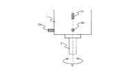
図1は、工作機械の振動情報表示装置の一例を示すブロック構成図、図2は、工作機械の主軸ハウジングの側面図、図3は、主軸ハウジングの正面図(軸方向下側から示した図)である。
1は、工作機械において主軸3を有する主軸ハウジングで、主軸3に保持させた工具を回転させて下方のテーブル上に載置したワークを加工する。この主軸ハウジング1には、C軸回りで回転可能に備えられた主軸3に生じる時間領域の振動(時間軸上の振動)を検出する手段として、加速度センサである振動センサ2a〜2cが備えられている。振動センサ2a〜2cは、互いに直角となる方向における振動情報を検出すべく、互いに直交するX軸、Y軸、Z軸方向での時間領域の振動情報を検出可能な状態で、主軸ハウジング1に取り付けられている。
Hereinafter, embodiments of the present invention will be described based on the drawings.
1 is a block diagram showing an example of a vibration information display apparatus for a machine tool, FIG. 2 is a side view of a spindle housing of the machine tool, and FIG. 3 is a front view of the spindle housing (a view from the lower side in the axial direction ).
A
振動情報表示装置10は、振動センサ2a〜2cにより検出された振動加速度を基にフーリエ解析を行うFFT演算装置11と、NC装置12とにより構成される。
NC装置12は、FFT演算装置11によってフーリエ解析された振動値(最大加速度)と、オペレータが設定したしきい値とを比較してびびり振動が発生したか否かを判断する振動情報取得手段としての振動判定部13を備えている。この振動判定部13において振動値がしきい値を上回り、且つ振動変化率が設定値を越えたと判断されると、その振動周波数が最適回転速度演算部14に送られる。最適回転速度演算部14は、特許文献1のような公知技術を利用してびびり振動を抑制する最適な主軸回転速度を算出して自動的に変更する。この最適回転速度の計算には、工具の刃数Zが必要であり、オペレータにより予め入力される。
The vibration
The
また、振動値がしきい値を上回り、且つ振動変化率が設定値を超えた場合、振動判定部13は、振動値を記憶手段としての記憶部15に記憶させると共に、稼働情報取得手段としての機械動作判定部16へ機械の稼働情報を記憶部15へ送るように指示を出す。ここで、機械の稼働情報とは、時刻、プログラム名、プログラムの実行コード、刃先位置、工具番号、主軸回転速度、送り速度、ワーク原点、工具長、機械座標、などである。機械動作判定部16は、オペレータによりプログラムが入力されるプログラム解釈部17からプログラム名や実行コードを取得し、工作機械に設けられた検出器等をモニタして主軸回転速度や送り速度、工具刃先の軌跡情報等を取得する。
こうして記憶部15に稼働情報が振動値と共に記憶されると、NC装置12に標準的に装備されている、NCプログラムや機械の現在位置等を表示するためのモニタ19に、表示制御手段としての表示制御部18によって振動情報として表示される。この振動情報は外部記憶装置20にも記録される。また、表示制御部18は、モニタ19に、工具刃先の軌跡と併せて振動情報を表示することもでき、オペレータから要求がある場合、振動情報を用いて最適回転速度演算部14で算出した最適速度の結果を表示することもできる。
In addition, when the vibration value exceeds the threshold and the vibration change rate exceeds the set value, the
When the operation information is stored together with the vibration value in the
以上の如く構成された振動情報表示装置10において、モニタ19に振動情報を表示するまでの手順を、図4のフローチャートに基づいて説明する。
まず、機械動作判定部16により現在の主軸回転速度を、FFT演算装置11により現在の振動値をそれぞれ取得する(S11)。次に、振動判定部13において、オペレータが予め設定したしきい値とFFT演算装置11により得られる振動とを比較(S12)し、検出した振動がしきい値よりも小さい場合はS11に戻る。S12でしきい値よりも検出した振動の方が大きい場合、予め設定した単位時間当たりの振動の変化率を監視する。すなわち、振動変化率が予め設定した値を越えたかどうかを判断し、越えてない場合は越えるまで待つ(S13)。そして、振動変化率が設定値を越えた場合、機械の稼働情報に、その時点の振動値と、振動抑制機能の発揮状況(最適回転速度演算部14による最適回転速度への変更の有無及び変更した場合の結果)とを加えて記憶部15に記録する(S14)。
In the vibration
First, the machine
この結果、図5に示すような記録データができあがる。1つの記録データは、時刻、プログラム名、プログラムの実行コード、工具刃先位置、工具番号、主軸回転速度、振動値等で構成される。このデータが作成されると図6のように表示制御部18によって新しいウインドウがモニタ19の画面の最前面に作成され、データの内容が表示される。このウインドウは、タッチパネル(入力手段)であるモニタ19上で「OK」ボタンを押すまで(機械の電源を切った後に再投入しても)表示され続ける。
ここで、「対策」ボタンを押すと、表示制御部18は、びびり振動の抑制対策に係る画面として、図8に示す安定限界線図を、例えば非特許文献1(モーダルパラメータを、びびり振動周波数から逆同定を行って同定する方法が示されている)にあるような技術を利用して作成して切替表示する。この時刃数などの安定限界線図の作成に必要な情報の設定項目は、ここの画面で設定することを可能としてあり、予め各項目を設定しておかなくても安定限界線図を表示させることを可能とする。よって、オペレータは、現在の回転速度で安定余裕が大きいか否かを認識でき、びびり振動の抑制に効果的な対策(安定余裕が大きい高回転側又は低回転側の何れに変更すればよいか)を容易に知ることができる。
As a result, recording data as shown in FIG. 5 is completed. One record data includes time, program name, program execution code, tool edge position, tool number, spindle rotational speed, vibration value and the like. When this data is created, a new window is created at the forefront of the screen of the
Here, when the “measure” button is pressed, the
一方、モニタ19には、図6の表示に代えて、図7に示すように、工具刃先の軌跡を表示すると共に、当該軌跡上に記録データを関連付けて表示するようにしてもよい。ここでは、びびり発生有無とびびり抑制動作の有無を記号で識別して軌跡上に配置している。よって、オペレータがそれぞれの記号を選択して入力手段である「対策」ボタンを押すことで、選択した加工部位についての安定限界線図が図8のように切替表示されるため、同様にびびり振動の抑制に効果的な対策を知ることができる。
On the other hand, instead of the display shown in FIG. 6, the trajectory of the cutting edge of the tool may be displayed on the
但し、加工部位が離れた位置で2ヶ所にある場合、工具刃先の軌跡の表示例は、図9のようになる。ここで部位1と部位2とでそれぞれびびり振動が生じているが、加工位置が異なるため機械特性が変化し、安定限界線図も部位1と部位2とで異なる場合がある。しかし、同一の工具で加工するなどの理由から、加工条件は両者そろえたいケースがある。よって、ここでは、選択されたすべての点で包括的に対策を表示させることで、部位1と2のそれぞれのびびり振動の対策を加味した図8より複雑な図10の安定限界線図を表示させるようにしている。
However, in the case where the processing site is at two distant locations, a display example of the trajectory of the cutting edge of the tool is as shown in FIG. Here, chatter vibration occurs in the
このように、上記形態の振動情報表示装置10によれば、びびり振動が検出された際の振動情報を取得する振動判定部13と、びびり振動が検出された際の工作機械の稼働情報を取得する機械動作判定部16と、取得された振動情報及び稼働情報を記憶する記憶部15と、記憶部15に記憶された振動情報及び稼働情報を振動抑制機能の発揮状況と併せて、又は、記憶部15に記憶された振動情報を振動抑制機能の発揮状況及び稼働情報に含まれる工具刃先の軌跡情報と併せてモニタ19に表示する表示制御部18と、を備えることで、工作機械のびびり振動の情報を稼働情報と共に瞬時にモニタ19に表示可能となる。よって、無人運転時に生じた加工異常について、機械に戻ったオペレータにいち早く知らせることができる。また、その場合に機械が自動的にびびり振動を抑制する動作を行ったのかどうかや、びびり振動が生じたプログラム、工具刃先位置等を把握することができる。
特にここでは、表示制御部18は、モニタ19の「対策」ボタンがタッチ操作されると、びびり振動の抑制対策に係る安定限界線図に切替表示するので、振動対策情報を容易に把握でき、その場で対応可能となる。よって、加工の最適化も素早く行うことができる
As described above, according to the vibration
In particular, here, since the
また、振動情報を振動抑制機能の発揮状況及び工具刃先の軌跡情報と併せてモニタ19に表示する場合、表示制御部18は、工具刃先の軌跡上にびびり振動の発生位置を表示し、当該発生位置を選択操作すると、選択した発生位置でのびびり振動の抑制対策に係る安定限界線図をモニタ19に切替表示すると共に、安定限界線図の作成に必要な刃数等の情報をモニタ19上で変更可能としている。よって、安定限界線図の作成に必要な情報もその場で設定することができ、事前の準備が無くても対策をすぐに参照することができる。
さらに、工具刃先の軌跡上のびびり振動の発生位置をモニタ19上で複数選択可能として、複数の発生位置を選択操作すると、選択した全ての発生位置でのびびり振動の抑制対策に係る安定限界線図をモニタ19に切替表示するので、機械の特性や加工状況の変化によって異なる原因で生じたびびり振動において、すべての原因を考慮した対策を知ることができる。
In addition, when the vibration information is displayed on the
Furthermore, when multiple occurrence positions of chatter vibration on the trajectory of the tool edge can be selected on
なお、上記形態では、振動検出をする手段として振動センサを採用したが、マイク、位置・回転検出器、主軸・送り軸モータの電流を用いることもできる。びびり振動の発生も、上記形態では振動のしきい値と振動変化率の設定値との双方と比較して判断しているが、しきい値のみと比較するようにしてもよい。また、振動抑制機能を有しない工作機械であっても、振動情報及稼働情報、工具刃先の軌跡情報を表示することで加工異常を迅速に知らせることは可能である。
さらに、稼働情報取得手段としては、NC装置内の機械動作判定部以外に、例えば稼働情報を、外部記憶装置やNC装置に接続されたネットワークを介して外部の演算装置に出力し、そこで加工状態の分析を行って分析結果を当該ネットワークを介してNC装置に送信することで構成してもよい。
In the above embodiment, although the vibration sensor is adopted as the means for detecting the vibration, it is also possible to use the current of a microphone, a position / rotation detector, or a spindle / feed axis motor. The generation of chattering is also judged in comparison with both the threshold value of vibration and the set value of vibration change rate in the above embodiment, but may be compared with only the threshold value. In addition, even with a machine tool that does not have a vibration suppression function, it is possible to quickly notify of processing abnormality by displaying vibration information, operation information, and trajectory information of the tool tip.
Furthermore, as the operation information acquisition means, besides the machine operation determination unit in the NC device, for example, the operation information is output to an external arithmetic device via an external storage device or a network connected to the NC device And the analysis result may be transmitted to the NC device via the network.
1・・工具ハウジング、2a〜2c・・振動センサ、3・・主軸、10・・振動情報表示装置、11・・FFT演算装置、12・・NC装置、13・・振動判定部、14・・最適回転速度演算部、15・・記憶部、16・・機械動作判定部、17・・プログラム解釈部、18・・表示制御部、19・・モニタ。
1 · · Tool housing, 2a-2c · · Vibration sensor, 3 · · Spindle, 10 · · Vibration information display device, 11 · · · FFT computing device, 12 · · NC device, 13 · · Vibration determination unit, 14 · · · Optimal rotational
Claims (4)
前記びびり振動が検出された際の振動情報を取得する振動情報取得手段と、
前記びびり振動が検出された際の前記工作機械の稼働情報を取得する稼働情報取得手段と、
取得された前記振動情報及び稼働情報を記憶する記憶手段と、
前記記憶手段に記憶された前記振動情報及び前記稼働情報を前記モニタに表示する、又は、前記記憶手段に記憶された前記振動情報を前記稼働情報に含まれる工具刃先の軌跡情報と併せて前記モニタに表示する表示制御手段と、を備える一方、
検出した前記びびり振動を抑制可能な振動抑制機能を備え、前記表示制御手段は、前記振動情報に前記振動抑制機能の発揮状況を併せて前記モニタに表示することを特徴とする工作機械の振動情報表示装置。 A monitor is provided on a machine tool provided with a vibration detection function that rotates a tool or a workpiece to process the workpiece and detects chatter vibration generated during the machining, and displays information related to the chatter vibration. A vibration information display device provided,
Vibration information acquisition means for acquiring vibration information when the chatter vibration is detected;
Operation information acquisition means for acquiring operation information of the machine tool when the chatter vibration is detected;
Storage means for storing the acquired vibration information and operation information;
The vibration information and the operation information stored in the storage means are displayed on the monitor, or the vibration information stored in the storage means is combined with the trajectory information of the tool blade edge included in the operation information, and the monitor And display control means for displaying on the
The vibration information of a machine tool characterized by comprising a vibration suppression function capable of suppressing the detected chatter vibration, and the display control means displaying the vibration information together with the performance condition of the vibration suppression function. Display device.
Priority Applications (4)
| Application Number | Priority Date | Filing Date | Title |
|---|---|---|---|
| JP2015110351A JP6538430B2 (en) | 2015-05-29 | 2015-05-29 | Vibration information display device for machine tools |
| US15/097,533 US10228677B2 (en) | 2015-05-29 | 2016-04-13 | Vibration information display device for machine tool that acquires information only during time that vibration value and rate of change exceed respective threshold |
| DE102016209080.1A DE102016209080A1 (en) | 2015-05-29 | 2016-05-25 | Vibration information display device for a machine tool |
| CN201610364832.0A CN106181581B (en) | 2015-05-29 | 2016-05-27 | Vibration information display device for machine tool |
Applications Claiming Priority (1)
| Application Number | Priority Date | Filing Date | Title |
|---|---|---|---|
| JP2015110351A JP6538430B2 (en) | 2015-05-29 | 2015-05-29 | Vibration information display device for machine tools |
Publications (2)
| Publication Number | Publication Date |
|---|---|
| JP2016224695A JP2016224695A (en) | 2016-12-28 |
| JP6538430B2 true JP6538430B2 (en) | 2019-07-03 |
Family
ID=57282011
Family Applications (1)
| Application Number | Title | Priority Date | Filing Date |
|---|---|---|---|
| JP2015110351A Active JP6538430B2 (en) | 2015-05-29 | 2015-05-29 | Vibration information display device for machine tools |
Country Status (4)
| Country | Link |
|---|---|
| US (1) | US10228677B2 (en) |
| JP (1) | JP6538430B2 (en) |
| CN (1) | CN106181581B (en) |
| DE (1) | DE102016209080A1 (en) |
Families Citing this family (31)
| Publication number | Priority date | Publication date | Assignee | Title |
|---|---|---|---|---|
| JP6595416B2 (en) * | 2016-08-09 | 2019-10-23 | ファナック株式会社 | Servo control device, spindle failure detection method using the servo control device, and computer program |
| JP2018073060A (en) * | 2016-10-27 | 2018-05-10 | オークマ株式会社 | Diagnostic result display method in diagnostic apparatus and diagnostic apparatus |
| WO2018119845A1 (en) * | 2016-12-29 | 2018-07-05 | 深圳配天智能技术研究院有限公司 | State detection method and system for numerical control machine tool |
| JP6266144B1 (en) * | 2017-01-27 | 2018-01-24 | Dmg森精機株式会社 | Vibration state detection device and machine tool provided with vibration state detection device |
| CN106970593B (en) * | 2017-04-18 | 2019-06-11 | 西安交通大学 | A method of realizing that processing flutter inhibits online by speed of mainshaft intelligent control |
| CN107150260B (en) * | 2017-05-17 | 2018-11-06 | 武汉工程大学 | A kind of orthogonal cutting flutter Analytic modeling method |
| EP3483679B1 (en) * | 2017-06-20 | 2020-10-07 | Yamazaki Mazak Corporation | Machine tool management system and machine tool management method |
| JP6560719B2 (en) * | 2017-07-27 | 2019-08-14 | ファナック株式会社 | Numerical control apparatus and numerical control method |
| US11002634B2 (en) * | 2017-08-24 | 2021-05-11 | Banner Engineering Corp | Vibrational alarms facilitated by determination of motor on-off state in variable-duty multi-motor machines |
| WO2019043742A1 (en) * | 2017-08-28 | 2019-03-07 | 三菱電機株式会社 | Numerical control device |
| JP2019095951A (en) * | 2017-11-21 | 2019-06-20 | 三菱重工工作機械株式会社 | Processing state display device, processing system, processing state display method, and program |
| JP6836496B2 (en) * | 2017-11-22 | 2021-03-03 | ファナック株式会社 | Noise monitoring device |
| JP6744342B2 (en) * | 2018-02-13 | 2020-08-19 | ファナック株式会社 | Machine tool controller |
| JP6675435B2 (en) * | 2018-04-27 | 2020-04-01 | Dmg森精機株式会社 | Machine tool, display method, and display program |
| JP6845192B2 (en) * | 2018-08-31 | 2021-03-17 | ファナック株式会社 | Processing environment measuring device |
| CN110873633A (en) * | 2018-09-03 | 2020-03-10 | 上海铼钠克数控科技股份有限公司 | Spindle vibration detection method and system |
| JP7277152B2 (en) * | 2019-01-22 | 2023-05-18 | ファナック株式会社 | Tool management system for machine tools |
| JP6959278B2 (en) * | 2019-02-27 | 2021-11-02 | ファナック株式会社 | Chatter vibration judgment device, machine learning device and system |
| JP7131454B2 (en) * | 2019-03-27 | 2022-09-06 | ブラザー工業株式会社 | Numerical controllers, machine tools, control programs, and storage media |
| CN113543912B (en) * | 2019-04-11 | 2023-12-26 | 西铁城时计株式会社 | Machine tool and sensing method |
| JP7403282B2 (en) * | 2019-11-01 | 2023-12-22 | オークマ株式会社 | Monitoring device and method for spindle rotation speed in machine tools, machine tools |
| DE102020208444A1 (en) | 2020-07-06 | 2022-01-13 | Magna powertrain gmbh & co kg | Process for manufacturing gear components |
| JP2022039715A (en) * | 2020-08-28 | 2022-03-10 | キヤノン株式会社 | Control device, imprint device, and article manufacturing method |
| CN112798097A (en) * | 2020-12-30 | 2021-05-14 | 重庆斯铂电气自动化设备有限公司 | Vibration monitoring system |
| JPWO2022208899A1 (en) * | 2021-04-03 | 2022-10-06 | ||
| JP6994596B1 (en) | 2021-06-28 | 2022-01-14 | Dmg森精機株式会社 | Machine tools and display controls |
| JP7022242B1 (en) * | 2021-06-28 | 2022-02-17 | Dmg森精機株式会社 | Machine tools and display controls |
| WO2023100314A1 (en) * | 2021-12-02 | 2023-06-08 | 株式会社Fuji | Machine tool |
| JP7192152B1 (en) | 2022-01-07 | 2022-12-19 | Dmg森精機株式会社 | Display controller and machine tool |
| JP7159494B1 (en) | 2022-01-07 | 2022-10-24 | Dmg森精機株式会社 | Display controller and machine tool |
| KR20230158308A (en) * | 2022-05-11 | 2023-11-20 | 주식회사 디엔솔루션즈 | Device and method for judging aging by measuring the dynamic characteristics of machine tools |
Family Cites Families (21)
| Publication number | Priority date | Publication date | Assignee | Title |
|---|---|---|---|---|
| JPH10328976A (en) | 1997-05-27 | 1998-12-15 | Hitachi Seiki Co Ltd | Machine tool operating information recording method, nc device with machine tool operating information recording function, and recording medium with machine tool operating information recording program recorded therein |
| US6085121A (en) * | 1997-09-22 | 2000-07-04 | Design & Manufacturing Solutions, Inc. | Device and method for recommending dynamically preferred speeds for machining |
| JPH11151638A (en) | 1997-11-17 | 1999-06-08 | Amada Eng Center Co Ltd | Machining vibration automatic detection system and machining vibration automatic detection control system |
| JP2000084798A (en) | 1998-09-10 | 2000-03-28 | Toshiba Corp | Machining abnormality detecting method and device, and machining controller |
| DE102005023317A1 (en) | 2005-05-20 | 2006-11-23 | P & L Gmbh & Co. Kg | Method for vibration optimization of a machine tool |
| JP4582660B2 (en) | 2007-05-24 | 2010-11-17 | オークマ株式会社 | Vibration suppressor for machine tools |
| US8256590B2 (en) * | 2007-05-24 | 2012-09-04 | Okuma Corporation | Vibration suppressing device and vibration suppressing method for machine tool |
| JP2009115481A (en) | 2007-11-02 | 2009-05-28 | Jfe Advantech Co Ltd | Diagnosis system of rotary machine facility |
| JP5234772B2 (en) * | 2008-10-28 | 2013-07-10 | オークマ株式会社 | Vibration suppression method and apparatus for machine tool |
| JP4648471B2 (en) | 2009-07-14 | 2011-03-09 | ファナック株式会社 | Tool trajectory display device for machine tools |
| JP5368232B2 (en) * | 2009-09-24 | 2013-12-18 | オークマ株式会社 | Vibration suppression device |
| US8700201B2 (en) | 2010-09-13 | 2014-04-15 | Okuma Corporation | Vibration suppressing device |
| JP5536608B2 (en) | 2010-10-13 | 2014-07-02 | オークマ株式会社 | Vibration suppressing method and vibration suppressing device for machine tool |
| JP5536611B2 (en) | 2010-10-15 | 2014-07-02 | オークマ株式会社 | Method and apparatus for monitoring machine tool, machine tool |
| JP5507409B2 (en) * | 2010-10-20 | 2014-05-28 | オークマ株式会社 | Method and apparatus for monitoring machine tool, machine tool |
| JP5631779B2 (en) | 2011-03-03 | 2014-11-26 | オークマ株式会社 | Vibration suppression method and apparatus for machine tool |
| JP5705074B2 (en) * | 2011-09-20 | 2015-04-22 | オークマ株式会社 | Method and apparatus for monitoring rotational speed of rotating shaft in machine tool, machine tool |
| US9294889B2 (en) * | 2012-07-13 | 2016-03-22 | Telefonaktiebolaget Lm Ericsson (Publ) | System and method for offline voicemail deposit |
| JP5819812B2 (en) * | 2012-12-25 | 2015-11-24 | ファナック株式会社 | Load indicator for machine tools |
| KR102191166B1 (en) * | 2013-06-10 | 2020-12-16 | 두산공작기계 주식회사 | Setting method of revolutions per minute on the real time of a spinning cutting tool, and the control device |
| US9682455B2 (en) * | 2014-10-28 | 2017-06-20 | Dmg Mori Seiki Co., Ltd. | Chatter application interface |
-
2015
- 2015-05-29 JP JP2015110351A patent/JP6538430B2/en active Active
-
2016
- 2016-04-13 US US15/097,533 patent/US10228677B2/en active Active
- 2016-05-25 DE DE102016209080.1A patent/DE102016209080A1/en active Pending
- 2016-05-27 CN CN201610364832.0A patent/CN106181581B/en active Active
Also Published As
| Publication number | Publication date |
|---|---|
| US10228677B2 (en) | 2019-03-12 |
| DE102016209080A1 (en) | 2016-12-01 |
| US20160346891A1 (en) | 2016-12-01 |
| JP2016224695A (en) | 2016-12-28 |
| CN106181581B (en) | 2020-01-10 |
| CN106181581A (en) | 2016-12-07 |
Similar Documents
| Publication | Publication Date | Title |
|---|---|---|
| JP6538430B2 (en) | Vibration information display device for machine tools | |
| JP5536611B2 (en) | Method and apparatus for monitoring machine tool, machine tool | |
| JP5608036B2 (en) | Operation history management method and operation history management device | |
| JP5710391B2 (en) | Processing abnormality detection device and processing abnormality detection method for machine tools | |
| JP5686760B2 (en) | Vibration discrimination method and vibration discrimination apparatus | |
| JP5507409B2 (en) | Method and apparatus for monitoring machine tool, machine tool | |
| CN106312687B (en) | Spindle load monitoring device for machine tool | |
| TWI472402B (en) | Tool flutter monitoring method | |
| JP6342593B1 (en) | Machine tool management system and machine tool management method | |
| JP2017033346A (en) | Information acquisition device for machine tool | |
| JP5955479B1 (en) | Display device | |
| CN102554692A (en) | Method and apparatus for suppressing vibration | |
| JP2012206230A (en) | Processing chatter detector and machine tool | |
| JP2014140918A (en) | Cutting vibration inhibition method, arithmetic control device, and machine tool | |
| JP6722052B2 (en) | Multi-blade tool abnormality detection method | |
| JP2016083759A (en) | Processing state monitoring method and system for work machine | |
| JP6456434B2 (en) | Vibration source estimation device | |
| JP2016052692A (en) | Numerical control apparatus | |
| JP6637689B2 (en) | Machine tool tool state determination device | |
| JP5660850B2 (en) | Vibration display device | |
| JP2016043443A (en) | Rotational speed display method | |
| JP2012056030A (en) | Machine tool | |
| JP2021086588A (en) | Diagnosis device, diagnosis device control method and program | |
| JP6944103B2 (en) | Machining status monitoring method and system for work machines | |
| JP2018073060A (en) | Diagnostic result display method in diagnostic apparatus and diagnostic apparatus |
Legal Events
| Date | Code | Title | Description |
|---|---|---|---|
| A621 | Written request for application examination |
Free format text: JAPANESE INTERMEDIATE CODE: A621 Effective date: 20171128 |
|
| A131 | Notification of reasons for refusal |
Free format text: JAPANESE INTERMEDIATE CODE: A131 Effective date: 20181218 |
|
| A977 | Report on retrieval |
Free format text: JAPANESE INTERMEDIATE CODE: A971007 Effective date: 20181220 |
|
| A521 | Written amendment |
Free format text: JAPANESE INTERMEDIATE CODE: A523 Effective date: 20190118 |
|
| TRDD | Decision of grant or rejection written | ||
| A01 | Written decision to grant a patent or to grant a registration (utility model) |
Free format text: JAPANESE INTERMEDIATE CODE: A01 Effective date: 20190514 |
|
| A61 | First payment of annual fees (during grant procedure) |
Free format text: JAPANESE INTERMEDIATE CODE: A61 Effective date: 20190606 |
|
| R150 | Certificate of patent or registration of utility model |
Ref document number: 6538430 Country of ref document: JP Free format text: JAPANESE INTERMEDIATE CODE: R150 |