JP6537765B2 - Hydraulic block for hydraulic unit of slip control hydraulic vehicle brake equipment - Google Patents
Hydraulic block for hydraulic unit of slip control hydraulic vehicle brake equipment Download PDFInfo
- Publication number
- JP6537765B2 JP6537765B2 JP2013111019A JP2013111019A JP6537765B2 JP 6537765 B2 JP6537765 B2 JP 6537765B2 JP 2013111019 A JP2013111019 A JP 2013111019A JP 2013111019 A JP2013111019 A JP 2013111019A JP 6537765 B2 JP6537765 B2 JP 6537765B2
- Authority
- JP
- Japan
- Prior art keywords
- hydraulic
- hydraulic block
- brake pressure
- valve
- mounting space
- Prior art date
- Legal status (The legal status is an assumption and is not a legal conclusion. Google has not performed a legal analysis and makes no representation as to the accuracy of the status listed.)
- Active
Links
- 238000013016 damping Methods 0.000 claims description 33
- 238000009434 installation Methods 0.000 claims description 7
- 208000029154 Narrow face Diseases 0.000 claims description 2
- 239000012530 fluid Substances 0.000 claims description 2
- 238000000926 separation method Methods 0.000 description 5
- 239000000872 buffer Substances 0.000 description 1
- 230000001419 dependent effect Effects 0.000 description 1
- 238000011161 development Methods 0.000 description 1
- 230000018109 developmental process Effects 0.000 description 1
- 238000010586 diagram Methods 0.000 description 1
- 238000004870 electrical engineering Methods 0.000 description 1
- 239000002184 metal Substances 0.000 description 1
- 230000010349 pulsation Effects 0.000 description 1
- 239000007787 solid Substances 0.000 description 1
- 238000009423 ventilation Methods 0.000 description 1
Images


Classifications
-
- B—PERFORMING OPERATIONS; TRANSPORTING
- B60—VEHICLES IN GENERAL
- B60T—VEHICLE BRAKE CONTROL SYSTEMS OR PARTS THEREOF; BRAKE CONTROL SYSTEMS OR PARTS THEREOF, IN GENERAL; ARRANGEMENT OF BRAKING ELEMENTS ON VEHICLES IN GENERAL; PORTABLE DEVICES FOR PREVENTING UNWANTED MOVEMENT OF VEHICLES; VEHICLE MODIFICATIONS TO FACILITATE COOLING OF BRAKES
- B60T8/00—Arrangements for adjusting wheel-braking force to meet varying vehicular or ground-surface conditions, e.g. limiting or varying distribution of braking force
- B60T8/32—Arrangements for adjusting wheel-braking force to meet varying vehicular or ground-surface conditions, e.g. limiting or varying distribution of braking force responsive to a speed condition, e.g. acceleration or deceleration
- B60T8/34—Arrangements for adjusting wheel-braking force to meet varying vehicular or ground-surface conditions, e.g. limiting or varying distribution of braking force responsive to a speed condition, e.g. acceleration or deceleration having a fluid pressure regulator responsive to a speed condition
-
- F—MECHANICAL ENGINEERING; LIGHTING; HEATING; WEAPONS; BLASTING
- F15—FLUID-PRESSURE ACTUATORS; HYDRAULICS OR PNEUMATICS IN GENERAL
- F15B—SYSTEMS ACTING BY MEANS OF FLUIDS IN GENERAL; FLUID-PRESSURE ACTUATORS, e.g. SERVOMOTORS; DETAILS OF FLUID-PRESSURE SYSTEMS, NOT OTHERWISE PROVIDED FOR
- F15B13/00—Details of servomotor systems ; Valves for servomotor systems
- F15B13/02—Fluid distribution or supply devices characterised by their adaptation to the control of servomotors
- F15B13/06—Fluid distribution or supply devices characterised by their adaptation to the control of servomotors for use with two or more servomotors
- F15B13/08—Assemblies of units, each for the control of a single servomotor only
- F15B13/0803—Modular units
-
- B—PERFORMING OPERATIONS; TRANSPORTING
- B60—VEHICLES IN GENERAL
- B60T—VEHICLE BRAKE CONTROL SYSTEMS OR PARTS THEREOF; BRAKE CONTROL SYSTEMS OR PARTS THEREOF, IN GENERAL; ARRANGEMENT OF BRAKING ELEMENTS ON VEHICLES IN GENERAL; PORTABLE DEVICES FOR PREVENTING UNWANTED MOVEMENT OF VEHICLES; VEHICLE MODIFICATIONS TO FACILITATE COOLING OF BRAKES
- B60T17/00—Component parts, details, or accessories of power brake systems not covered by groups B60T8/00, B60T13/00 or B60T15/00, or presenting other characteristic features
- B60T17/02—Arrangements of pumps or compressors, or control devices therefor
-
- B—PERFORMING OPERATIONS; TRANSPORTING
- B60—VEHICLES IN GENERAL
- B60T—VEHICLE BRAKE CONTROL SYSTEMS OR PARTS THEREOF; BRAKE CONTROL SYSTEMS OR PARTS THEREOF, IN GENERAL; ARRANGEMENT OF BRAKING ELEMENTS ON VEHICLES IN GENERAL; PORTABLE DEVICES FOR PREVENTING UNWANTED MOVEMENT OF VEHICLES; VEHICLE MODIFICATIONS TO FACILITATE COOLING OF BRAKES
- B60T8/00—Arrangements for adjusting wheel-braking force to meet varying vehicular or ground-surface conditions, e.g. limiting or varying distribution of braking force
- B60T8/32—Arrangements for adjusting wheel-braking force to meet varying vehicular or ground-surface conditions, e.g. limiting or varying distribution of braking force responsive to a speed condition, e.g. acceleration or deceleration
- B60T8/34—Arrangements for adjusting wheel-braking force to meet varying vehicular or ground-surface conditions, e.g. limiting or varying distribution of braking force responsive to a speed condition, e.g. acceleration or deceleration having a fluid pressure regulator responsive to a speed condition
- B60T8/36—Arrangements for adjusting wheel-braking force to meet varying vehicular or ground-surface conditions, e.g. limiting or varying distribution of braking force responsive to a speed condition, e.g. acceleration or deceleration having a fluid pressure regulator responsive to a speed condition including a pilot valve responding to an electromagnetic force
- B60T8/3615—Electromagnetic valves specially adapted for anti-lock brake and traction control systems
- B60T8/3675—Electromagnetic valves specially adapted for anti-lock brake and traction control systems integrated in modulator units
- B60T8/368—Electromagnetic valves specially adapted for anti-lock brake and traction control systems integrated in modulator units combined with other mechanical components, e.g. pump units, master cylinders
-
- B—PERFORMING OPERATIONS; TRANSPORTING
- B60—VEHICLES IN GENERAL
- B60T—VEHICLE BRAKE CONTROL SYSTEMS OR PARTS THEREOF; BRAKE CONTROL SYSTEMS OR PARTS THEREOF, IN GENERAL; ARRANGEMENT OF BRAKING ELEMENTS ON VEHICLES IN GENERAL; PORTABLE DEVICES FOR PREVENTING UNWANTED MOVEMENT OF VEHICLES; VEHICLE MODIFICATIONS TO FACILITATE COOLING OF BRAKES
- B60T8/00—Arrangements for adjusting wheel-braking force to meet varying vehicular or ground-surface conditions, e.g. limiting or varying distribution of braking force
- B60T8/32—Arrangements for adjusting wheel-braking force to meet varying vehicular or ground-surface conditions, e.g. limiting or varying distribution of braking force responsive to a speed condition, e.g. acceleration or deceleration
- B60T8/34—Arrangements for adjusting wheel-braking force to meet varying vehicular or ground-surface conditions, e.g. limiting or varying distribution of braking force responsive to a speed condition, e.g. acceleration or deceleration having a fluid pressure regulator responsive to a speed condition
- B60T8/40—Arrangements for adjusting wheel-braking force to meet varying vehicular or ground-surface conditions, e.g. limiting or varying distribution of braking force responsive to a speed condition, e.g. acceleration or deceleration having a fluid pressure regulator responsive to a speed condition comprising an additional fluid circuit including fluid pressurising means for modifying the pressure of the braking fluid, e.g. including wheel driven pumps for detecting a speed condition, or pumps which are controlled by means independent of the braking system
-
- F—MECHANICAL ENGINEERING; LIGHTING; HEATING; WEAPONS; BLASTING
- F15—FLUID-PRESSURE ACTUATORS; HYDRAULICS OR PNEUMATICS IN GENERAL
- F15B—SYSTEMS ACTING BY MEANS OF FLUIDS IN GENERAL; FLUID-PRESSURE ACTUATORS, e.g. SERVOMOTORS; DETAILS OF FLUID-PRESSURE SYSTEMS, NOT OTHERWISE PROVIDED FOR
- F15B13/00—Details of servomotor systems ; Valves for servomotor systems
- F15B13/02—Fluid distribution or supply devices characterised by their adaptation to the control of servomotors
- F15B13/06—Fluid distribution or supply devices characterised by their adaptation to the control of servomotors for use with two or more servomotors
- F15B13/08—Assemblies of units, each for the control of a single servomotor only
- F15B13/0803—Modular units
- F15B13/0807—Manifolds
- F15B13/0814—Monoblock manifolds
-
- F—MECHANICAL ENGINEERING; LIGHTING; HEATING; WEAPONS; BLASTING
- F15—FLUID-PRESSURE ACTUATORS; HYDRAULICS OR PNEUMATICS IN GENERAL
- F15B—SYSTEMS ACTING BY MEANS OF FLUIDS IN GENERAL; FLUID-PRESSURE ACTUATORS, e.g. SERVOMOTORS; DETAILS OF FLUID-PRESSURE SYSTEMS, NOT OTHERWISE PROVIDED FOR
- F15B13/00—Details of servomotor systems ; Valves for servomotor systems
- F15B13/02—Fluid distribution or supply devices characterised by their adaptation to the control of servomotors
- F15B13/06—Fluid distribution or supply devices characterised by their adaptation to the control of servomotors for use with two or more servomotors
- F15B13/08—Assemblies of units, each for the control of a single servomotor only
- F15B13/0803—Modular units
- F15B13/0871—Channels for fluid
-
- F—MECHANICAL ENGINEERING; LIGHTING; HEATING; WEAPONS; BLASTING
- F15—FLUID-PRESSURE ACTUATORS; HYDRAULICS OR PNEUMATICS IN GENERAL
- F15B—SYSTEMS ACTING BY MEANS OF FLUIDS IN GENERAL; FLUID-PRESSURE ACTUATORS, e.g. SERVOMOTORS; DETAILS OF FLUID-PRESSURE SYSTEMS, NOT OTHERWISE PROVIDED FOR
- F15B13/00—Details of servomotor systems ; Valves for servomotor systems
- F15B13/02—Fluid distribution or supply devices characterised by their adaptation to the control of servomotors
- F15B13/06—Fluid distribution or supply devices characterised by their adaptation to the control of servomotors for use with two or more servomotors
- F15B13/08—Assemblies of units, each for the control of a single servomotor only
- F15B13/0803—Modular units
- F15B13/0878—Assembly of modular units
- F15B13/0885—Assembly of modular units using valves combined with other components
- F15B13/0892—Valves combined with fluid components
-
- Y—GENERAL TAGGING OF NEW TECHNOLOGICAL DEVELOPMENTS; GENERAL TAGGING OF CROSS-SECTIONAL TECHNOLOGIES SPANNING OVER SEVERAL SECTIONS OF THE IPC; TECHNICAL SUBJECTS COVERED BY FORMER USPC CROSS-REFERENCE ART COLLECTIONS [XRACs] AND DIGESTS
- Y10—TECHNICAL SUBJECTS COVERED BY FORMER USPC
- Y10T—TECHNICAL SUBJECTS COVERED BY FORMER US CLASSIFICATION
- Y10T137/00—Fluid handling
- Y10T137/8593—Systems
- Y10T137/877—With flow control means for branched passages
- Y10T137/87885—Sectional block structure
Landscapes
- Engineering & Computer Science (AREA)
- Physics & Mathematics (AREA)
- Fluid Mechanics (AREA)
- Mechanical Engineering (AREA)
- Transportation (AREA)
- Electromagnetism (AREA)
- General Engineering & Computer Science (AREA)
- Regulating Braking Force (AREA)
- Valves And Accessory Devices For Braking Systems (AREA)
Description
本発明は、請求項1の前提項の構成要件を備える、スリップコントロール式の油圧車両ブレーキ設備のハイドロリックユニットのための油圧ブロックに関する。
The invention relates to a hydraulic block for a hydraulic unit of a slip-controlled hydraulic vehicle brake installation comprising the features of the preamble of
このような種類の油圧ブロックは周知である。これは典型的には、スリップコントロール式の車両ブレーキ設備の油圧ポンプ、電磁弁、油圧リザーバ、ダンピングチャンバのような油圧コンポーネントを取り付けるための、高さの低い直方体の金属ブロックである。油圧ブロックは油圧コンポーネントを機械的に保持し、典型的には穿設される接続管路によってこれらを油圧接続する。油圧コンポーネントを装備した油圧ブロックがハイドロリックユニットを構成し、スリップコントロールの中核部分となる。高さが低いとは、油圧ブロックが、長さや幅の約4分の1から3分の1、稀には半分を超える厚みをしばしば有することを意味している。平面図で見ると油圧ブロックは長方形であり、しばしば近似的に正方形である。油圧ブロックの中には、通常、各コンポーネントの油圧部品だけがある。電磁弁のコイルや電機子のような電気機械部品は、油圧ブロックから突出している。同様に、油圧ポンプを駆動するための電動モータも、油圧ブロックの外側に取り付けられている。 Such types of hydraulic blocks are well known. It is typically a low profile rectangular solid metal block for mounting hydraulic components such as slip control vehicle brake equipment hydraulic pumps, solenoid valves, hydraulic reservoirs, damping chambers. The hydraulic block mechanically holds the hydraulic components and hydraulically connects them, typically by means of drilled connection lines. A hydraulic block equipped with hydraulic components constitutes a hydraulic unit, which is the core of slip control. Low height means that the hydraulic block often has a thickness of about one-quarter to one-third, rarely more than half, of the length and width. Viewed in plan view, the hydraulic block is rectangular, often approximately square. In the hydraulic block, there are usually only the hydraulic components of each component. Electromechanical components such as solenoid valve coils and armatures protrude from the hydraulic block. Similarly, an electric motor for driving the hydraulic pump is also attached to the outside of the hydraulic block.
このような油圧ブロックは特許文献1から公知である。この公知の油圧ブロックは、ブレーキ増圧弁およびブレーキ減圧弁のための収容部を有している。ブレーキ増圧弁のための収容部は、相並んで1列に油圧ブロックに配置されている。ブレーキ減圧弁のための収容部は、ブレーキ増圧弁のための収容部の列と平行な別の列として油圧ブロックに配置されている。 Such a hydraulic block is known from U.S. Pat. This known hydraulic block has a housing for the brake pressure increase valve and the brake pressure reduction valve. The receptacles for the brake pressure-increasing valves are arranged side by side in one row in the hydraulic block. The receptacle for the brake pressure reducing valve is arranged in the hydraulic block as a separate row parallel to the row of receptacles for the brake pressure increasing valve.
請求項1の構成要件を備える本発明の油圧ブロックは、ブレーキ増圧弁およびブレーキ減圧弁のための収容部のそれぞれの列の間で油圧ブロックに配置された、ダンピングチャンバのための取付スペースを有している。ダンピングチャンバのための取付スペースは、ブレーキ増圧弁およびブレーキ減圧弁のためのそれぞれの収容部の間に配置されていてよく、または、それ以外の高さないし平面で油圧ブロックに配置されていてよい。ダンピングチャンバのための取付スペースは、ブレーキ増圧弁およびブレーキ減圧弁のためのそれぞれの収容部が延びている各列と平行に配置されるのが好ましく、すなわちダンピングチャンバのための取付スペースは、ブレーキ増圧弁およびブレーキ減圧弁のためのそれぞれの収容部に対して直角に油圧ブロックに配置されており、油圧ブロックの幅狭面で開口している。油圧的には、ダンピングチャンバは車両ブレーキ設備のスリップコントロールの油圧ポンプの圧力側に接続されており、リターンポンプと呼ばれることが多い油圧ポンプの圧力脈動を緩衝する。
The hydraulic block according to the invention with the features of
本発明の利点は、ハイドロリックユニットにダンピングチャンバが省スペースに格納されることにある。 An advantage of the invention is that the damping unit is stored space-saving in the hydraulic unit.
従属請求項は、請求項1に記載された発明の好ましい実施形態と発展例を対象としている。
The dependent claims are directed to preferred embodiments and developments of the invention as claimed in
次に、実施例を参照しながら本発明について詳しく説明する。図面は次のものを示している: The invention will now be described in detail with reference to examples. The drawings show the following:
油圧ブロックは、穿設部を図示するために透視した図面で示している。それぞれの図は、本発明を図解、解説するための模式化、簡略化した図面である。 The hydraulic block is shown in a perspective view to illustrate the drilled portion. Each figure is a schematic and simplified drawing for illustrating and explaining the present invention.
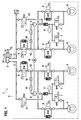
図1に示すスリップコントロール式の油圧式の2系統車両ブレーキ設備1は、ハイドロリックユニット2と、ハイドロリックユニット2が接続された2系統メインブレーキシリンダ3と、ハイドロリックユニット2に接続されたホイールブレーキ4とを有している。ハイドロリックユニット2は、次の段落で説明する、車両ブレーキ設備1のスリップコントロールの油圧コンポーネントを含んでいる。
The slip control hydraulic two-system
車両ブレーキ設備1の各々のブレーキ回路I,IIは、分離弁5を介して、メインブレーキシリンダ3に接続されている。ホイールブレーキ4は、ブレーキ増圧弁6を介して、分離弁5に接続されている。ブレーキ減圧弁7を介して各々のブレーキ回路I,IIにおいて、油圧リザーバ8および油圧ポンプ9の吸込側がホイールブレーキ4に接続されている。しばしばリターンポンプとも呼ばれる両方の油圧ポンプ9は、電動モータ10によって一緒に駆動される。油圧ポンプの圧力側にはダンピングチャンバ11が接続されており、このダンピングチャンバは、分離弁5とブレーキ増圧弁6をつなぐ接続管路13にスロットル12によって接続されている。さらに車両ブレーキ設備1は、油圧ポンプ9の吸込側をメインブレーキシリンダ3と接続する吸込弁14を、各々のブレーキ回路I,IIに有している。このようなスリップコントロール式の車両ブレーキ設備1の構造や機能は周知であり、ここでは詳しくは説明しない。
Each brake circuit I, II of the
車両ブレーキ設備1のスリップコントロールのハイドロリックユニット2の油圧コンポーネントは、図2と図3に示す油圧ブロック15に格納されている。油圧ブロック15は、車両ブレーキ設備1のハイドロリックユニット2ないしスリップコントロールの油圧コンポーネントの、機械的な取付と油圧的な配管の役目をする。各コンポーネントの油圧部品は油圧ブロックの収容部、取付スペース等にあり、電磁弁のコイルや電機子といった電気工学・電気機械の部品は、油圧ブロック15から外方に突き出している。油圧ポンプ9を駆動するための電動モータ10は、油圧ブロック15の外側に取り付けられている。油圧ブロック15は未装備のまま図示されており、すなわち、油圧コンポーネントなしに図示されている。収容部は、油圧ブロック15にある部分的に直径に段差のついた円筒状の穴であり、油圧的な配管のために、穴は接続管路または一般的に管路として油圧ブロック15に設けられている。収容部および管路は相互に、および油圧ブロック15のエッジや外面に対して、平行または直角に配置されており、すなわちデカルト座標系に配置されている。油圧ブロック15は高さの低い直方体であり、その厚みは長さまたは幅のおよそ4分の1であり、見かけ上は略正方形である。一義的な名称づけと区別をするために、図2に見ることができる油圧ブロック15の平坦面を前面16と呼び、図3に見ることができる平坦面を裏面17と呼び、それぞれの側面を縦面18および横面19と呼ぶ。油圧ブロック15は、仮想的な長手方向の中心平面に対して鏡像対称である。
The hydraulic components of the slip control hydraulic unit 2 of the
油圧ブロック15は横面19に、相並んで1列に配置された、ホイールブレーキ4のための4つの接続部4’を有している。「1列に」とは、本実施例では、接続部4’等が仮想的な直線上に相並んで配置されることを意味している。接続部4’は円筒状の止まり穴であり、そこから少なくとも1つの管路20が他の接続部、電磁弁の収容部、油圧ポンプの取付スペース、油圧リザーバ、および/またはダンピングチャンバへと通じている。これらの管路は油圧ブロック15の穴であり、それが接続部、収容部、または取付スペースを起点とするのでない場合には、油圧ブロック15のいずれかの面16,17,18,19の開口部で、たとえば押し込まれたボールによって気密に密封されて閉じられる。接続部4’は、ホイールブレーキ管路を接続するための雌ねじを有することができ、または、たとえばホイールブレーキ管路を接続するために嵌込み固定のようなかしめを行うことが意図されていてよい。油圧ブロック15の横面19に配置されているとは、接続部4’がこの横面19で開いており、それにより、ホイールブレーキ管路を接続することができることを意味している。油圧ポンプや油圧リザーバのための取付スペースの場合、油圧ブロック15の面に配置されるとは、油圧ブロック15のこの面で取付スペースが開いており、それにより、この面を起点として油圧ポンプまたは油圧リザーバの挿入ないし組付けをすることができることを意味している。同様のことは、電磁弁の収容部についても当てはまる。
The
油圧ブロック15の横面19から、ホイールブレーキ4のための接続部4’の深さに略相当する間隔をおいて、油圧ブロック15の裏面17に、メインブレーキシリンダ3の両方のブレーキ回路I,I1のための2つの接続部3’がある。メインブレーキシリンダ3のための接続部3’は、ホイールブレーキ4のための外側および内側の接続部4’の間にそれぞれ配置されている。
Both brake circuits I of the
メインブレーキシリンダ3のための接続部3’に後続して、ブレーキ増圧弁6のための4つの収容部6’が1列に相並んで、油圧ブロック15の前面16に配置されている。ブレーキ増圧弁6のための収容部6’は、すでに述べた管路20によって、ホイールブレーキ4のための接続部4’と接続されている。
Following the connection 3 'for the
ブレーキ増圧弁6のための収容部6’と平行な別の1つの列に、ホイールブレーキ4のための接続部4’とは反対を向いているほうのブレーキ増圧弁6のための収容部6’の側に、ブレーキ減圧弁7のための収容部7’が相並んで油圧ブロック15の前面16に配置されている。
The
ブレーキ減圧弁7のための収容部7’には油圧ポンプ9のための取付スペース9’が後続しており、これらの取付スペースは油圧ブロック15の縦面18に配置されており、すなわち開いており、ブレーキ増圧弁6およびブレーキ減圧弁7のための相並んで配置された収容部6’,7’の各列と平行に延びている。油圧ポンプ9のための取付スペース9’は、油圧ブロック15の比較的深くまで入り込んでおり、直径を狭める2つの直径段部の後で、ピストンポンプとして構成された油圧ポンプ9を駆動する電動モータ10のシャフトに回転不能に配置された、ここには図示しないポンプ偏心器のための偏心器スペース10’へ半径方向に開口している。偏心器スペース10’は油圧ブロック15の裏面17で開いており、油圧ポンプ9のためのそれぞれの取付スペース9’の間の中央部にある。図示しない電動モータ10は、油圧ブロック15の裏面17の外側で、偏心器スペース10’と同軸に取り付けられている。
The housing 7 'for the brake
ブレーキ増圧弁6およびブレーキ減圧弁7のための収容部6’,7’の列と平行な別の列では、ブレーキ増圧弁6およびブレーキ減圧弁7のための収容部6’,7’と反対を向いているほうの油圧ポンプ9のための取付スペース9’の側に、分離弁5および吸込弁14のための4つの収容部5’,14’が、油圧ブロック15の前面16に相並んで配置されている。分離弁5のための収容部5’は、吸込弁14のためのそれぞれの収容部14’の間に配置されている。
In another row parallel to the row of the
分離弁5および吸込弁14のための収容部5’,14’の列には、油圧リザーバ8のための2つの取付スペース8’が後続している。これらの取付スペース8’は、ホイールブレーキ4のための接続部4’が配置された横面19と向かい合う、油圧ブロック15の横面に配置されている。
The row of
ブレーキ増圧弁6およびブレーキ減圧弁7のための収容部6’,7’の両方の列の間には、ダンピングチャンバ11のための2つの取付スペース11’が配置されている。ダンピングチャンバ11のための取付スペース11’は、油圧ブロック15の縦面18に配置されており、すなわち、そこでダンピングチャンバ11の取付のために開いており、ブレーキ増圧弁6およびブレーキ減圧弁7のための収容部6’,7’の各列と平行に延びている。ブレーキ増圧弁6およびブレーキ減圧弁7のための収容部6’,7’は、前述したように、油圧ブロック15の前面16に配置されている。ダンピングチャンバ11のための取付スペース11’は、油圧ブロック15の裏面17の近傍に配置されており、すなわち、油圧ブロック15の上面16から見て、ブレーキ増圧弁6およびブレーキ減圧弁7のための収容部6’,7’の下で、油圧ブロック15に配置されている。
Two mounting
ダンピングチャンバ11のための取付スペース11’には、スロットル12を形成する、穴を備えたディスク12’が挿入される。ダンピングチャンバ11のための取付スペース11’は、ダンピングチャンバ11のための取付スペース11’の開口部に挿入されて溶接される、たとえば超音波溶接される、もしくはかしめられるカバー21により、気密に密封されて耐圧式に閉止される。油圧的に見ると、スロットル12を形成するディスク12’は、ディスク12’の一方の側にある油圧リザーバ8と、他方の側にある分離弁5およびブレーキ増圧弁6との間にある。
In the mounting
ダンピングチャンバ11のための取付スペース11’はその底面で、取付スペース11’と軸平行の短い接続管路22によって接続管路13と接続されており(図3参照)、この接続管路は、分離弁5のための収容部5’を、ブレーキ増圧弁6のための内側に配置された収容部6’と接続する。他の両方のブレーキ増圧弁6のための外側に位置する収容部6’は、横穴24によって、ブレーキ増圧弁6のための内側に配置された収容部6’と接続されている。管路13は、油圧ブロック15の縦面18と平行に延びるとともに、油圧ポンプ9のための取付スペース9’およびダンピングチャンバ11のための取付スペース11’に対して垂直に延びている。管路13は、ホイールブレーキ4のための接続部4’が配置された幅狭面19で開口しており、そこで図示しない押し込まれたボールによって耐圧式かつ気密に密封して閉止される。ダンピングチャンバ11のための取付スペース11’の接続管路13への接続管路22は、前述したように、取付スペース11’と軸平行かつ偏心的に、ホイールブレーキ4のための接続部4’が配置されている油圧ブロック15の横面19のほうを向く、取付スペース11’の円周の個所に配置されている。このことは、組立が完成した油圧ブロック15に、すなわち車両ブレーキ設備1のスリップコントロールの油圧コンポーネントを装備した油圧ブロックに、ブレーキ液を充填するときの換気を可能にし、ないしは簡素化する。
The mounting
ダンピングチャンバ11のための取付スペース11’を、ブレーキ増圧弁6のための収容部6’と、ブレーキ減圧弁7のための収容部7’との間に配置することで、ダンピングチャンバ11を省スペースに油圧ブロック15に格納することができる。
By arranging the mounting
油圧ブロック15はデカルト座標で穿設されており、すなわち収容部、取付スペース、管路などは相互に、および油圧ブロック15の各面に対して、平行または直角に穿設されている。
The
1 油圧車両ブレーキ設備
6 ブレーキ増圧弁
6’ ブレーキ増圧弁のための収容部
7 ブレーキ減圧弁
7’ ブレーキ減圧弁のための収容部
11 ダンピングチャンバ
11’ ダンピングチャンバのための取付スペース
15 油圧ブロック
16 前面
17 裏面
18 縦面
19 横面、幅狭面
DESCRIPTION OF
Claims (6)
前記ダンピングチャンバ(11)のための前記取付スペース(11’)は分離弁(5)のための収容部(5’)および/またはブレーキ増圧弁(6)のための収容部(6’)への接続管路(22)を前記油圧ブロック(15)に有しており、前記接続管路(22)は前記油圧ブロック(15)の縦面(18)に対して垂直に配置されるとともに、前記ダンピングチャンバ(11)のための前記取付スペース(11’)に連通していることを特徴とする油圧ブロック。 A receptacle (6 ') for the brake pressure intensifying valve (6) and a receptacle (6') for the brake pressure intensifying valve (6), arranged one behind the other in the hydraulic block (15) A slip control type hydraulic vehicle brake installation (1), having a receptacle (7 ') for the brake pressure reducing valve (7), arranged parallel to the one in the row and next to the hydraulic block (15) Hydraulic block for the hydraulic unit (2), wherein the hydraulic block (15) comprises the receptacle (6 ', 7') for the brake pressure intensifying valve (6) and the brake pressure reducing valve (7). wherein between each row of) arranged in a hydraulic block (15), have a mounting space (11 ') for damping chamber (11),
The mounting space (11 ') for the damping chamber (11) is to a receptacle (5') for the separating valve (5) and / or a receptacle (6 ') for the brake pressure intensifying valve (6) The connection line (22) is disposed in the hydraulic block (15), and the connection line (22) is disposed perpendicularly to the vertical surface (18) of the hydraulic block (15), wherein said mounting space (11 ') in communication with the hydraulic block, characterized in Rukoto for damping chamber (11).
Applications Claiming Priority (2)
| Application Number | Priority Date | Filing Date | Title |
|---|---|---|---|
| DE102012209218.8 | 2012-05-31 | ||
| DE201210209218 DE102012209218A1 (en) | 2012-05-31 | 2012-05-31 | Hydraulic block for a hydraulic unit of a slip-controlled, hydraulic vehicle brake system |
Publications (2)
| Publication Number | Publication Date |
|---|---|
| JP2013249055A JP2013249055A (en) | 2013-12-12 |
| JP6537765B2 true JP6537765B2 (en) | 2019-07-03 |
Family
ID=49579431
Family Applications (1)
| Application Number | Title | Priority Date | Filing Date |
|---|---|---|---|
| JP2013111019A Active JP6537765B2 (en) | 2012-05-31 | 2013-05-27 | Hydraulic block for hydraulic unit of slip control hydraulic vehicle brake equipment |
Country Status (5)
| Country | Link |
|---|---|
| US (1) | US9404514B2 (en) |
| JP (1) | JP6537765B2 (en) |
| KR (1) | KR20130135130A (en) |
| CN (1) | CN103448711B (en) |
| DE (1) | DE102012209218A1 (en) |
Families Citing this family (19)
| Publication number | Priority date | Publication date | Assignee | Title |
|---|---|---|---|---|
| DE102013209727A1 (en) * | 2013-05-24 | 2014-11-27 | Robert Bosch Gmbh | Hydraulic block for a slip-controlled vehicle brake system |
| DE102014208871A1 (en) * | 2014-05-12 | 2015-11-12 | Robert Bosch Gmbh | Hydraulic block for a hydraulic unit of a slip control of a hydraulic vehicle brake system |
| CN104176031A (en) * | 2014-08-20 | 2014-12-03 | 浙江万向精工有限公司 | Hydraulic control unit body device |
| DE102015117568A1 (en) | 2014-10-17 | 2016-04-21 | Mando Corporation | HYDRAULIC UNIT OF AN ELECTRONICALLY CONTROLLED BRAKING SYSTEM |
| DE102016212721A1 (en) * | 2016-07-13 | 2018-01-18 | Robert Bosch Gmbh | Hydraulic block for a hydraulic unit of a slip control |
| DE102016225761A1 (en) * | 2016-09-07 | 2018-03-08 | Robert Bosch Gmbh | Hydraulic block for a hydraulic unit of a slip control of a hydraulic vehicle brake system |
| EP3558776B1 (en) * | 2016-09-07 | 2021-03-31 | Robert Bosch GmbH | Hydraulic block for a hydraulic assembly of a slip control system of a hydraulic vehicle brake system |
| JP2018095027A (en) | 2016-12-12 | 2018-06-21 | ローベルト ボッシュ ゲゼルシャフト ミット ベシュレンクテル ハフツング | Fluid pressure control unit of vehicular brake system |
| JP2018095028A (en) | 2016-12-12 | 2018-06-21 | ローベルト ボッシュ ゲゼルシャフト ミット ベシュレンクテル ハフツング | Fluid pressure control unit of vehicular brake system, and vehicular brake system |
| DE102017203752A1 (en) * | 2017-03-08 | 2018-09-13 | Robert Bosch Gmbh | Hydraulic block for a hydraulic unit of a slip control of a hydraulic vehicle brake system |
| KR102006497B1 (en) * | 2017-05-11 | 2019-10-08 | 주식회사 만도 | Valve block for electronic control brake system |
| JP2019111997A (en) * | 2017-12-26 | 2019-07-11 | ロベルト・ボッシュ・ゲゼルシャフト・ミト・ベシュレンクテル・ハフツングRobert Bosch Gmbh | Liquid pressure control unit of saddle-riding type vehicular brake system and saddle-riding type vehicular brake system |
| KR102098569B1 (en) * | 2018-08-09 | 2020-04-08 | 주식회사 만도 | Valve block for hydraulic brake system |
| CN109630489B (en) * | 2018-11-06 | 2024-02-27 | 襄阳航宇机电液压应用技术有限公司 | Electrohydraulic pressure servo valve |
| KR102602359B1 (en) * | 2018-11-22 | 2023-11-16 | 에이치엘만도 주식회사 | Check valve and moudulator block including it |
| DE102018221715A1 (en) | 2018-12-13 | 2020-06-18 | Robert Bosch Gmbh | Electronically slip-controllable brake system, in particular for a motor vehicle |
| CN110203184B (en) * | 2019-05-06 | 2024-05-24 | 万向钱潮股份公司 | An ABS hydraulic block for energy recovery in electric vehicles |
| KR102507730B1 (en) * | 2020-11-03 | 2023-03-07 | 현대모비스 주식회사 | Hydraulic Block for Electronic Brake System for Vehicle |
| KR102633262B1 (en) | 2021-10-25 | 2024-02-02 | 현대모비스 주식회사 | Brake Apparatus for Vehicle |
Family Cites Families (13)
| Publication number | Priority date | Publication date | Assignee | Title |
|---|---|---|---|---|
| JP3364990B2 (en) * | 1992-08-28 | 2003-01-08 | 株式会社デンソー | Anti-skid device |
| DE19542582A1 (en) * | 1995-11-15 | 1997-05-22 | Teves Gmbh Alfred | Electrohydraulic unit for pressure control in motor vehicle brake systems |
| JPH1047256A (en) * | 1996-08-07 | 1998-02-17 | Unisia Jecs Corp | Pump liquid pressure damper structure in antiskid control device |
| EP1030799B1 (en) * | 1997-11-14 | 2002-09-25 | Continental Teves AG & Co. oHG | Hydraulic aggregate for slip-controlled braking systems |
| JP4114366B2 (en) * | 2002-02-20 | 2008-07-09 | 株式会社デンソー | Brake device for vehicle |
| DE10339882A1 (en) * | 2003-06-26 | 2005-01-13 | Continental Teves Ag & Co. Ohg | Hydraulic unit for slip-controlled brake systems |
| KR101042875B1 (en) * | 2003-06-26 | 2011-06-20 | 콘티넨탈 테베스 아게 운트 코. 오하게 | Hydraulic units for sliding brake systems |
| DE102004030625A1 (en) * | 2003-10-10 | 2005-06-16 | Continental Teves Ag & Co. Ohg | hydraulic power unit |
| US7441843B2 (en) * | 2003-10-10 | 2008-10-28 | Continental Teves Ag & Co., Ohg | Hydraulic unit |
| US7407234B1 (en) * | 2005-09-17 | 2008-08-05 | Robert Bosch Gmbh | Manual assembly to ABS/TCS/ESP hydraulic units |
| DE102005047355B4 (en) * | 2005-10-04 | 2014-06-18 | Robert Bosch Gmbh | Hydraulic connection for a vehicle assembly |
| DE102006059924B4 (en) | 2006-12-19 | 2019-06-27 | Robert Bosch Gmbh | Hydraulic block of a hydraulic unit and hydraulic unit with such a hydraulic block |
| US20080179944A1 (en) * | 2007-01-29 | 2008-07-31 | Continental Teves, Inc. | Hydraulic anti-lock brake system |
-
2012
- 2012-05-31 DE DE201210209218 patent/DE102012209218A1/en active Pending
-
2013
- 2013-05-27 JP JP2013111019A patent/JP6537765B2/en active Active
- 2013-05-29 CN CN201310216436.XA patent/CN103448711B/en active Active
- 2013-05-30 KR KR20130061587A patent/KR20130135130A/en active IP Right Grant
- 2013-05-30 US US13/905,544 patent/US9404514B2/en not_active Expired - Fee Related
Also Published As
| Publication number | Publication date |
|---|---|
| US20130319562A1 (en) | 2013-12-05 |
| DE102012209218A1 (en) | 2013-12-05 |
| CN103448711A (en) | 2013-12-18 |
| CN103448711B (en) | 2016-12-28 |
| US9404514B2 (en) | 2016-08-02 |
| JP2013249055A (en) | 2013-12-12 |
| KR20130135130A (en) | 2013-12-10 |
Similar Documents
| Publication | Publication Date | Title |
|---|---|---|
| JP6537765B2 (en) | Hydraulic block for hydraulic unit of slip control hydraulic vehicle brake equipment | |
| JP6295030B2 (en) | Hydraulic block for slip control type vehicle brake system | |
| US10093294B2 (en) | Hydraulic block for a hydraulic assembly of a slip control system of a hydraulic vehicle brake system | |
| CN110382315B (en) | Hydraulic block for a hydraulic unit of a slip control device of a hydraulic vehicle brake system | |
| US9517757B2 (en) | Hydraulic block for a hydraulic assembly of a slip-regulated, hydraulic vehicle brake system, and a hydraulic vehicle brake system | |
| JP6391298B2 (en) | Hydraulic block for slip-controlled vehicle brake system | |
| KR20180123130A (en) | Driving device for hydraulic drive system | |
| KR101659269B1 (en) | Pump housing of a motor vehicle hydraulic unit with at least one main cylinder connection opening | |
| JP2010532289A (en) | Hydraulic unit for controlling brake pressure in a vehicle brake device | |
| US10864896B2 (en) | Hydraulic block for a hydraulic assembly of a slip control system of a hydraulic vehicle brake system | |
| CN110099829B (en) | Hydraulic block for a hydraulic unit of a slip control device of a hydraulic vehicle brake system | |
| JP2023553646A (en) | Rectangular parallelepiped hydraulic block for hydraulic units for brake pressure control in hydraulic vehicle brake equipment | |
| KR20220143069A (en) | Hydraulic block for hydraulic units of hydraulic external force vehicle brake systems | |
| KR20230123440A (en) | Hydraulic block for a hydraulic unit of a hydraulic braking system with external power | |
| JP7546139B2 (en) | Hydraulic block for hydraulic units for slip control in hydraulic vehicle brake systems | |
| CN113165620B (en) | Square hydraulic block for a hydraulic assembly of a slip control device of a hydraulic vehicle brake system | |
| JP2019520267A (en) | Hydraulic block for slip control hydraulic unit | |
| KR20230123439A (en) | Hydraulic block for a hydraulic braking system with external power |
Legal Events
| Date | Code | Title | Description |
|---|---|---|---|
| RD04 | Notification of resignation of power of attorney |
Free format text: JAPANESE INTERMEDIATE CODE: A7424 Effective date: 20130923 |
|
| A621 | Written request for application examination |
Free format text: JAPANESE INTERMEDIATE CODE: A621 Effective date: 20160510 |
|
| A977 | Report on retrieval |
Free format text: JAPANESE INTERMEDIATE CODE: A971007 Effective date: 20170208 |
|
| A131 | Notification of reasons for refusal |
Free format text: JAPANESE INTERMEDIATE CODE: A131 Effective date: 20170213 |
|
| A601 | Written request for extension of time |
Free format text: JAPANESE INTERMEDIATE CODE: A601 Effective date: 20170425 |
|
| A521 | Request for written amendment filed |
Free format text: JAPANESE INTERMEDIATE CODE: A523 Effective date: 20170724 |
|
| A131 | Notification of reasons for refusal |
Free format text: JAPANESE INTERMEDIATE CODE: A131 Effective date: 20171108 |
|
| A601 | Written request for extension of time |
Free format text: JAPANESE INTERMEDIATE CODE: A601 Effective date: 20180206 |
|
| A521 | Request for written amendment filed |
Free format text: JAPANESE INTERMEDIATE CODE: A523 Effective date: 20180226 |
|
| A131 | Notification of reasons for refusal |
Free format text: JAPANESE INTERMEDIATE CODE: A131 Effective date: 20180612 |
|
| A601 | Written request for extension of time |
Free format text: JAPANESE INTERMEDIATE CODE: A601 Effective date: 20180829 |
|
| A601 | Written request for extension of time |
Free format text: JAPANESE INTERMEDIATE CODE: A601 Effective date: 20181102 |
|
| A521 | Request for written amendment filed |
Free format text: JAPANESE INTERMEDIATE CODE: A523 Effective date: 20181203 |
|
| TRDD | Decision of grant or rejection written | ||
| A01 | Written decision to grant a patent or to grant a registration (utility model) |
Free format text: JAPANESE INTERMEDIATE CODE: A01 Effective date: 20190510 |
|
| A61 | First payment of annual fees (during grant procedure) |
Free format text: JAPANESE INTERMEDIATE CODE: A61 Effective date: 20190605 |
|
| R150 | Certificate of patent or registration of utility model |
Ref document number: 6537765 Country of ref document: JP Free format text: JAPANESE INTERMEDIATE CODE: R150 |
|
| R250 | Receipt of annual fees |
Free format text: JAPANESE INTERMEDIATE CODE: R250 |
|
| R250 | Receipt of annual fees |
Free format text: JAPANESE INTERMEDIATE CODE: R250 |
|
| R250 | Receipt of annual fees |
Free format text: JAPANESE INTERMEDIATE CODE: R250 |