JP6536282B2 - Stacker crane - Google Patents
Stacker crane Download PDFInfo
- Publication number
- JP6536282B2 JP6536282B2 JP2015163233A JP2015163233A JP6536282B2 JP 6536282 B2 JP6536282 B2 JP 6536282B2 JP 2015163233 A JP2015163233 A JP 2015163233A JP 2015163233 A JP2015163233 A JP 2015163233A JP 6536282 B2 JP6536282 B2 JP 6536282B2
- Authority
- JP
- Japan
- Prior art keywords
- mast
- face roller
- face
- distance
- roller
- Prior art date
- Legal status (The legal status is an assumption and is not a legal conclusion. Google has not performed a legal analysis and makes no representation as to the accuracy of the status listed.)
- Active
Links
- 238000005096 rolling process Methods 0.000 claims description 13
- 239000000463 material Substances 0.000 description 13
- 230000004048 modification Effects 0.000 description 11
- 238000012986 modification Methods 0.000 description 11
- 230000001133 acceleration Effects 0.000 description 7
- 230000003028 elevating effect Effects 0.000 description 7
- 230000001105 regulatory effect Effects 0.000 description 7
- 238000000034 method Methods 0.000 description 4
- 230000002093 peripheral effect Effects 0.000 description 4
- 230000008859 change Effects 0.000 description 3
- 239000004677 Nylon Substances 0.000 description 2
- 238000005452 bending Methods 0.000 description 2
- 229920001778 nylon Polymers 0.000 description 2
- 239000011347 resin Substances 0.000 description 2
- 229920005989 resin Polymers 0.000 description 2
- 230000000087 stabilizing effect Effects 0.000 description 2
- 229910000831 Steel Inorganic materials 0.000 description 1
- 239000006096 absorbing agent Substances 0.000 description 1
- 239000000853 adhesive Substances 0.000 description 1
- 230000001070 adhesive effect Effects 0.000 description 1
- 230000008901 benefit Effects 0.000 description 1
- 238000010276 construction Methods 0.000 description 1
- 230000008878 coupling Effects 0.000 description 1
- 238000010168 coupling process Methods 0.000 description 1
- 238000005859 coupling reaction Methods 0.000 description 1
- 230000000694 effects Effects 0.000 description 1
- 230000000149 penetrating effect Effects 0.000 description 1
- 230000008569 process Effects 0.000 description 1
- 230000009467 reduction Effects 0.000 description 1
- 230000035939 shock Effects 0.000 description 1
- 239000010959 steel Substances 0.000 description 1
- 239000013585 weight reducing agent Substances 0.000 description 1
Images


Landscapes
- Warehouses Or Storage Devices (AREA)
- Forklifts And Lifting Vehicles (AREA)
Description
本願発明は、自動倉庫において荷物の搬送作業を行うスタッカクレーンに関する。 The present invention relates to a stacker crane which carries out an operation of transferring a load in an automatic warehouse.
従来、複数の荷物を収容可能なラックへの荷物の収容及びラックからの荷物の取出しを行うスタッカクレーンが存在する。 2. Description of the Related Art Conventionally, there are stacker cranes that store luggage in a rack capable of storing a plurality of packages and remove packages from the rack.
スタッカクレーンは、例えば、ラックに沿って床面に設けられた下部レール上を走行する走行台車と、走行台車に立設されたマストと、マストに沿って昇降する昇降台とを備える。スタッカクレーンは、昇降台に設置された移載装置によってラックとの間での荷物の受け渡しを行う。昇降台は、マストの表面を転動するフェイスローラを備える(特許文献1参照)。特許文献1に記載されたスタッカクレーンでは、昇降台がマストに沿って昇降する際に、昇降台はフェイスローラの転動面だけにおいてマストと当接する。これにより、特許文献1に記載されたスタッカクレーンでは、昇降台とマストとの間の接触抵抗が低減される。 The stacker crane includes, for example, a traveling carriage that travels on a lower rail provided on a floor surface along the rack, a mast erected on the traveling carriage, and a lift platform that moves up and down along the mast. The stacker crane delivers the package to and from the rack by means of a transfer device installed at the elevator platform. The lifting platform comprises a face roller that rolls on the surface of the mast (see Patent Document 1). In the stacker crane described in Patent Document 1, when the lift platform moves up and down along the mast, the lift platform contacts the mast only at the rolling surface of the face roller. Thereby, in the stacker crane described in Patent Document 1, the contact resistance between the lifting platform and the mast is reduced.
また、特許文献1に記載されたスタッカクレーンでは、バネによりフェイスローラをマスト向きに付勢することにより、フェイスローラとマストとを当接させている。このように、当該スタッカクレーンでは、マスト間の間隔が変化する場合でも、フェイスローラとマストを常に当接させることにより、昇降台のマストに対する位置を安定化させようとしている。 Further, in the stacker crane described in Patent Document 1, the face roller is brought into contact with the mast by urging the face roller toward the mast with a spring. As described above, in the stacker crane, even when the distance between the masts changes, the position of the elevator platform with respect to the mast is stabilized by always contacting the face roller and the mast.
しかしながら、特許文献1に記載されたスタッカクレーンは、以下に述べる問題を有する。スタッカクレーンでは、下部レールに沿って高速に移動するため、走行中の加速度が大きい。このため、スタッカクレーンの加減速時に、マストと昇降台との間で水平方向に大きな力が加わる。このような場合にも、フェイスローラとマストとの当接を維持するためには、バネによる付勢力を大きくする必要がある。しかしながら、バネによる付勢力を大きくすると、マストとフェイスローラとの間に、常に大きな力が加わる。このため、マストが撓むことにより、ラックに対する移載装置の相対位置が変化する。また、マストが撓むことにより、マストの寿命が短縮される。さらに、フェイスローラとマストとの間に加わる圧力を低減するために、フェイスローラ及びその周辺部品の大型化が必要となる。 However, the stacker crane described in Patent Document 1 has the following problems. In a stacker crane, the acceleration during traveling is large because it moves at high speed along the lower rail. Therefore, a large horizontal force is applied between the mast and the lifting platform when the stacker crane accelerates and decelerates. Even in such a case, in order to maintain the contact between the face roller and the mast, it is necessary to increase the biasing force of the spring. However, when the biasing force by the spring is increased, a large force is always applied between the mast and the face roller. For this reason, when the mast bends, the relative position of the transfer device with respect to the rack changes. Also, bending the mast reduces the life of the mast. Furthermore, in order to reduce the pressure applied between the face roller and the mast, it is necessary to increase the size of the face roller and its peripheral parts.
本願発明は、上記従来の課題を考慮し、昇降台のマストに対する位置を安定化させ、かつ、マスト及びフェイスローラに加わる力を抑制できるスタッカクレーンを提供することを目的とする。 An object of the present invention is to provide a stacker crane capable of stabilizing the position of the lifting platform relative to the mast and suppressing the force applied to the mast and the face roller in consideration of the above-mentioned conventional problems.
上記目的を達成するために、本発明の一態様に係るスタッカクレーンは、ラックに沿って配置された軌道を走行するスタッカクレーンであって、昇降台と、前記昇降台をガイドする第一のマストと、を備え、前記昇降台は、前記ラックとの間で荷物を移載する移載装置と、前記移載装置と前記第一のマストとの間に配置され、前記第一のマストの第一の表面を転動する第一のフェイスローラであって、前記第一のマスト寄りの第一の突出位置と、前記第一の突出位置より前記移載装置寄りの第一の退避位置との間において移動可能な第一のフェイスローラと、前記第一のフェイスローラを前記第一の退避位置から前記第一の突出位置へ向けて付勢する第一の付勢部材と、前記移載装置と前記第一のマストとの間に配置された第二のフェイスローラとを備え、前記第一のフェイスローラは、前記第一のマスト寄りの第一の端部を有し、前記第二のフェイスローラは、前記第一のマスト寄りの第二の端部を有し、前記第一のフェイスローラが前記第一の突出位置に配置される場合における前記第一の端部から前記第一の表面までの距離は、前記第二の端部から前記第一の表面までの距離より小さく、かつ、前記第一のフェイスローラが前記第一の退避位置に配置される場合における前記第一の端部から前記第一の表面までの距離は、前記第二の端部から前記第一の表面までの距離以上である。 In order to achieve the above object, a stacker crane according to an aspect of the present invention is a stacker crane that travels along a track disposed along a rack, and includes a lifting platform and a first mast that guides the lifting platform. And the lift table is disposed between the transfer device for transferring a load to and from the rack, and between the transfer device and the first mast, and A first face roller rolling on one surface, the first projecting position closer to the first mast, and the first retracted position closer to the transfer device than the first projecting position A first face roller movable between the first face roller, a first biasing member biasing the first face roller from the first retracted position toward the first projecting position, and the transfer device A second face ring placed between the first and the first mast And the first face roller has a first end closer to the first mast, and the second face roller has a second end closer to the first mast. The distance from the first end to the first surface when the first face roller is disposed at the first projecting position is the distance from the second end to the first surface. The distance from the first end to the first surface when the first face roller is smaller than the distance to the surface and the first face roller is disposed in the first retracted position is the second end Or greater than the distance from the portion to the first surface.
この構成によれば、第一のフェイスローラが第一のマストに向けて付勢されていることから、第一のフェイスローラが第一のマストに当接する。これにより、昇降台の各マストに対する相対位置を安定化できる。また、スタッカクレーンの加減速時に第一のフェイスローラと第一のマストとの間に加わる力が、第一の付勢部材の付勢力より大きい場合には、第一のフェイスローラが第一の退避位置に移動するため、第二のフェイスローラが第一のマストに当接する。このため、第一のフェイスローラと第一のマストとの当接部に加わる力が、第一のフェイスローラと第二のフェイスローラとに分散される。したがって、第一のフェイスローラと第一のマストとの間に加わる力を抑制できるため、各フェイスローラ及び第一のマストが変形又は損傷することを抑制できる。さらに、第一のフェイスローラと第一のマストとの間に加わる力が大きい場合でも、第二のフェイスローラが第一のマストに当接することにより、昇降台がスムーズに昇降できる状態が維持される。 According to this configuration, since the first face roller is biased toward the first mast, the first face roller abuts on the first mast. This makes it possible to stabilize the relative position of the elevator platform to each mast. When the force applied between the first face roller and the first mast at the time of acceleration or deceleration of the stacker crane is larger than the biasing force of the first biasing member, the first face roller is the first A second face roller abuts the first mast for movement to the retracted position. For this reason, the force applied to the contact portion between the first face roller and the first mast is dispersed to the first face roller and the second face roller. Therefore, since the force applied between the first face roller and the first mast can be suppressed, deformation or damage of each face roller and the first mast can be suppressed. Furthermore, even when the force applied between the first face roller and the first mast is large, the second face roller abuts on the first mast, so that the elevator platform can be moved up and down smoothly. Ru.
また、以上のように、第一の付勢部材の付勢力を、スタッカクレーンの加減速時に第一のフェイスローラと第一のマストとの間に加わる力より小さくすることができるため、各マスト及び各フェイスローラに常に加わる力を、抑制することができる。したがって、各フェイスローラ及びマストが変形及び損傷することを抑制できる。 Further, as described above, since the biasing force of the first biasing member can be smaller than the force applied between the first face roller and the first mast at the time of acceleration and deceleration of the stacker crane, each mast And the force always applied to each face roller can be suppressed. Therefore, deformation and damage of each face roller and mast can be suppressed.
また、本発明の一態様に係るスタッカクレーンにおいて、前記第二のフェイスローラは、前記第一のマスト寄りの第二の突出位置と、前記第二の突出位置より前記移載装置寄りの第二の退避位置との間において移動可能であり、前記昇降台は、前記第二のフェイスローラを前記第二の退避位置から前記第二の突出位置へ向けて、前記第一の付勢部材より強い力で付勢する第二の付勢部材と、前記移載装置と前記第一のマストとの間に配置され、前記第一のマストに対向する第一の対向部を有する第一のストッパとをさらに備え、前記第二のフェイスローラが前記第二の突出位置に配置される場合における前記第二の端部から前記第一の表面までの距離は、前記第一の対向部から前記第一の表面までの距離より小さく、かつ、前記第二のフェイスローラが前記第二の退避位置に配置される場合における前記第二の端部から前記第一の表面までの距離は、前記第一の対向部から前記第一の表面までの距離以上であってもよい。 Further, in the stacker crane according to one aspect of the present invention, the second face roller is provided with a second projecting position closer to the first mast and a second projecting roller closer to the transfer device than the second projecting position. And the elevator platform is stronger than the first biasing member with the second face roller directed from the second retracted position to the second projecting position. A force-biasing second biasing member, and a first stopper disposed between the transfer device and the first mast and having a first opposing portion facing the first mast And a distance from the second end to the first surface when the second face roller is disposed at the second projecting position is the distance from the first opposing portion to the first surface. Less than the distance to the surface of the When the roller is disposed at the second retracted position, the distance from the second end to the first surface is equal to or greater than the distance from the first opposing portion to the first surface. It is also good.
これによれば、第二の付勢部材の付勢力以上の力が第二のフェイスローラと第一のマストとの間に加わる場合に、当該力を、各フェイスローラ及びストッパに分散させることができる。このため、各フェイスローラに加わる力を抑制することができる。したがって、各フェイスローラ及びマストが変形又は損傷することを抑制できる。 According to this, when a force equal to or greater than the biasing force of the second biasing member is applied between the second face roller and the first mast, the force can be dispersed to the face rollers and the stoppers. it can. For this reason, the force added to each face roller can be suppressed. Therefore, deformation or damage of each face roller and mast can be suppressed.
また、本発明の一態様に係るスタッカクレーンにおいて、前記スタッカクレーンは、前記昇降台を案内する第二のマストをさらに備え、前記第二のマストは、前記昇降台に対して、前記第一のマストの反対側に配置され、前記昇降台は、前記移載装置と前記第二のマストとの間に配置され、前記第二のマストの第二の表面を転動する第三のフェイスローラであって、前記第二のマスト寄りの第三の突出位置と、前記第三の突出位置より前記移載装置寄りの第三の退避位置との間において移動可能であり、かつ、前記第一のフェイスローラより径の大きい第三のフェイスローラと、前記第三のフェイスローラを前記第三の退避位置から前記第三の突出位置へ向けて前記第一の付勢部材より強い力で付勢する第三の付勢部材とを備えてもよい。 Further, in the stacker crane according to one aspect of the present invention, the stacker crane further includes a second mast for guiding the elevator platform, and the second mast is the first platform relative to the elevator platform. A lifter is disposed on the opposite side of the mast, with a third face roller disposed between the transfer device and the second mast and rolling on the second surface of the second mast Movable between a third projecting position closer to the second mast and a third retracted position closer to the transfer device than the third projecting position, and the first The third face roller having a diameter larger than that of the face roller and the third face roller are urged from the third retracted position toward the third projecting position with a stronger force than the first urging member. A third biasing member may be provided.
この構成によれば、第三の付勢部材より弱い力で、第一のフェイスローラが第一のマストに向けて付勢されることにより、第一のフェイスローラが第一のマストに当接する。また、昇降台は、第一の付勢部材によって第二のマスト向きに付勢されるため、第三のフェイスローラが第二のマストに当接する。ここで、第三の付勢部材の付勢力は、第一の付勢部材の付勢力より大きいため、第三のフェイスローラは突出位置に配置された状態を維持する。すなわち、第一のフェイスローラと移載装置との相対位置は、両マスト間の間隔の変化に応じて変動するが、第三のフェイスローラと移載装置との相対位置はほぼ変動しない。したがって、この構成によれば、第三のフェイスローラと移載装置との相対位置を安定化させることができる。ここで、第三のフェイスローラは、第二のマストに当接しているため、移載装置の第二のマストに対する相対位置を安定化させることができる。これにより、荷物の移載位置を安定化させることができる。 According to this configuration, by biasing the first face roller toward the first mast with a weaker force than the third biasing member, the first face roller abuts the first mast . Further, since the elevator platform is biased toward the second mast by the first biasing member, the third face roller abuts on the second mast. Here, since the biasing force of the third biasing member is larger than the biasing force of the first biasing member, the third face roller is maintained in the projecting position. That is, although the relative position of the first face roller and the transfer device fluctuates according to the change of the distance between the two masts, the relative position of the third face roller and the transfer device does not substantially fluctuate. Therefore, according to this configuration, the relative position between the third face roller and the transfer device can be stabilized. Here, since the third face roller is in contact with the second mast, the relative position of the transfer device with respect to the second mast can be stabilized. Thereby, the transfer position of the load can be stabilized.
また、本発明の一態様に係るスタッカクレーンにおいて、前記昇降台は、前記移載装置と前記第二のマストとの間に配置され、前記第二のマストに対向する第二の対向部を有する第二のストッパをさらに備え、前記第三のフェイスローラが前記第三の突出位置に配置される場合における前記第三のフェイスローラの前記第二のマスト寄りの第三の端部から前記第二の表面までの距離は、前記第二の対向部から前記第二の表面までの距離より小さく、かつ、前記第三のフェイスローラが前記第三の退避位置に配置される場合における前記第三の端部から前記第二の表面までの距離は、前記第二の対向部から前記第二の表面までの距離以上であってもよい。 Further, in the stacker crane according to one aspect of the present invention, the elevator platform is disposed between the transfer device and the second mast, and has a second facing portion facing the second mast. The third end of the third face roller closer to the second mast from the third end in the case where the third face roller is disposed in the third projecting position, further comprising a second stopper The distance to the surface of is smaller than the distance from the second opposing portion to the second surface, and the third face roller is disposed at the third retraction position. The distance from the end to the second surface may be equal to or greater than the distance from the second facing portion to the second surface.
この構成によれば、第三の付勢部材の付勢力以上の力が第三のフェイスローラと第二のマストとの間に加わる場合に、第二のストッパが第二のマストに当接する。これにより、第三のフェイスローラと第二のマストとの当接部に加わる力を、ストッパに分散させることができるため、第三のフェイスローラ及び第二のマストに加わる力を抑制することができる。したがって、各フェイスローラ及びマストが変形又は損傷することを抑制できる。 According to this configuration, the second stopper abuts on the second mast when a force equal to or greater than the biasing force of the third biasing member is applied between the third face roller and the second mast. Thereby, the force applied to the contact portion between the third face roller and the second mast can be dispersed to the stopper, so that the force applied to the third face roller and the second mast can be suppressed. it can. Therefore, deformation or damage of each face roller and mast can be suppressed.
本発明によれば、昇降台のマストに対する位置を安定化させ、かつ、マスト及びフェイスローラに加わる力を抑制できるスタッカクレーンを提供することができる。 ADVANTAGE OF THE INVENTION According to this invention, the stacker crane which can stabilize the position with respect to the mast of a raising / lowering stand and can suppress the force added to a mast and a face roller can be provided.
以下に、本発明の実施形態に係るスタッカクレーンについて、図面を参照しながら説明する。なお、各図は、模式図であり、必ずしも厳密に図示したものではない。 Hereinafter, a stacker crane according to an embodiment of the present invention will be described with reference to the drawings. Each figure is a schematic view and is not necessarily strictly illustrated.
また、以下で説明する実施の形態は、包括的又は具体的な例を示すものである。以下の実施の形態で示される数値、形状、材料、構成要素、構成要素の配置位置及び接続形態などは、一例であり、本発明を限定する主旨ではない。また、以下の実施の形態における構成要素のうち、最上位概念を示す独立請求項に記載されていない構成要素については、任意の構成要素として説明される。 In addition, the embodiments described below show general or specific examples. The numerical values, shapes, materials, components, arrangement positions and connection forms of the components, and the like described in the following embodiments are merely examples, and are not intended to limit the present invention. Further, among the components in the following embodiments, components not described in the independent claim indicating the highest concept are described as arbitrary components.
(実施の形態)
[1.自動倉庫及びスタッカクレーンの全体構成]
まず、図1を用いて、実施の形態に係る自動倉庫100及びスタッカクレーン50の構成の概要を説明する。
Embodiment
[1. Overall Configuration of Automatic Warehouse and Stacker Crane]
First, the outline of the configuration of the
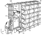
図1は、本実施の形態における自動倉庫100の構成概要を示す斜視図である。
FIG. 1 is a perspective view showing an outline of the configuration of an
図1に示されるように、実施の形態における自動倉庫100は、複数の荷物90を収容可能なラック80とスタッカクレーン50とを備える。
As shown in FIG. 1, the
スタッカクレーン50は、ラック80に沿って配置された軌道を走行する搬送車であり、昇降台51と、昇降台51をガイドするマスト30a及び30bと、を備える。本実施の形態では、自動倉庫100は、スタッカクレーン50が走行する軌道として、下部レール12を備える。スタッカクレーン50は走行台車20をさらに備える。
The
昇降台51はマスト30a及び30bに沿って昇降する台である。本実施の形態では、昇降台51は2本のマスト30a及び30bの間に配置される。昇降台51には、フェイスローラ64を含む複数のフェイスローラが備えられており、昇降台51は、これらのフェイスローラが2本のマスト30a及び30bに当接した状態で、当該2本のマスト30a及び30bによってガイドされながら昇降する。昇降台51には移載装置52が配置されている。本実施の形態における移載装置52は、スライドフォークによって荷物90の移載を行う移載方法を採用しているが、移載装置52が採用する移載方法に特に限定はない。
The
走行台車20は、下部レール12に沿って走行する台車である。本実施の形態では、走行台車20には、2本のマスト30a及び30bが鉛直方向(図1のZ軸方向)に立設されている。なお、図1では表されていないが、2本のマスト30a及び30bの上端部は、例えば、上部レールに沿って走行する上部台車と接続されている。つまり、走行台車20が下部レール12に沿って走行し、かつ、上部台車が上部レールに沿って走行することで、スタッカクレーン50全体として図1におけるX軸方向(すなわち、上部レール及び下部レール12に沿った方向)に移動する。
The traveling
マスト30a及び30bは、昇降台51をガイドする柱状部材である。マスト30a及び30bの構造については、フェイスローラの構成と合わせて後述する。
The
以上のような構成を有するスタッカクレーン50は、下部レール12に沿って走行し、昇降台51を昇降させ、かつ、移載装置52のスライドフォークを図1のY軸方向に出退させる。スタッカクレーン50は、このような構成を採用することで、ラック80及びステーション58等との間での荷物90の受け渡しを行うことができる。
The
なお、ステーション58は、荷物90の一時的な載置場所であり、例えばラック80に収容されている荷物90は、一時的にステーション58に置かれた後に、自動倉庫100の外部に運び出される。
The
本実施の形態におけるスタッカクレーン50は、マスト30a及び30bと昇降台51との当接部に相当するフェイスローラ周辺の構造に特徴を有する。以下、フェイスローラ及びその周辺の構造を中心に説明する。
The
[2.フェイスローラとマストとの位置関係及びマストの構造]
続いて、各フェイスローラと各マストとの位置関係及びマストの構造について図2及び図3を用いて説明する。
[2. Positional relationship between face roller and mast and structure of mast]
Subsequently, the positional relationship between each face roller and each mast and the structure of the mast will be described with reference to FIGS. 2 and 3.
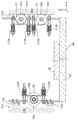
図2は、本実施の形態に係る一方のマスト30aの断面構造、及び、マスト30aと各フェイスローラとの位置関係を示す図である。
FIG. 2 is a view showing the cross-sectional structure of one
図3は、本実施の形態に係る他方のマスト30bの断面構造、及び、マスト30bと各フェイスローラとの位置関係を示す図である。
FIG. 3 is a view showing a cross-sectional structure of the
図2及び図3に示されるように、本実施の形態に係るスタッカクレーン50の昇降台51は、マスト30aに当接するフェイスローラ61及び64と、マスト30bに当接するフェイスローラ63及び64とを備える。なお、図2には示されないが、昇降台51はマスト30a側にフェイスローラ62をさらに備える。フェイスローラ62については、後述する。
As shown in FIG. 2 and FIG. 3, the
図2に示されるように、フェイスローラ61は、マスト30aのX軸方向端部のうち移載装置寄りの端部に位置するに表面である第二当接面31bに当接する第一のフェイスローラである。図2に示されるように、二つのフェイスローラ61が、マスト30aの第二当接面31bに当接する位置にそれぞれ設けられる。本実施の形態では、二つのフェイスローラ61は、それぞれ、Y軸方向に並べて配置される。
As shown in FIG. 2, the
図2及び図3には示されないが、フェイスローラ62は、マスト30aのX軸方向端部のうち移載装置寄りの端部に位置するに表面である第二当接面31bの近傍に配置される第二のフェイスローラである。二つのフェイスローラ62が、マスト30aの第二当接面31bの近傍にそれぞれ設けられる。本実施の形態では、二つのフェイスローラ62は、それぞれ、Y軸方向に並べて配置される。また、二つのフェイスローラ62は、それぞれ、二つのフェイスローラ61とZ軸方向(鉛直方向)において隣り合う位置に配置される。
Although not shown in FIGS. 2 and 3, the
図3に示されるように、フェイスローラ63は、マスト30bのX軸方向(スタッカクレーンの走行方向)端部のうち移載装置寄りの端部に位置するに表面である第二当接面31bに当接する第三のフェイスローラである。図2に示されるように、二つのフェイスローラ63が、マスト30bの第二当接面31bに当接する位置にそれぞれ設けられる。本実施の形態では、二つのフェイスローラ63は、それぞれ、Y軸方向に並べて配置される。
As shown in FIG. 3, the
図2及び図3に示されるように、フェイスローラ64は、マスト30a及び30bのY軸方向(スタッカクレーンの走行方向及び鉛直方向に垂直な方向)端部に位置する表面である第一当接面31aに当接する第四のフェイスローラである。図2に示されるように、二つのフェイスローラ64が、マスト30aの二つの第一当接面31aに当接する位置にそれぞれ設けられる。また、図3に示されるように、二つのフェイスローラ64が、マスト30bの二つの第一当接面31aに当接する位置にそれぞれ設けられる。
As shown in FIGS. 2 and 3, the
図2に示されるように、フェイスローラ64の回転軸64aとフェイスローラ61の回転軸61aとは互いに交差する関係にある。フェイスローラ64とフェイスローラ61とは、互いの回転軸が交差するように配置されていればよく、フェイスローラ64及びフェイスローラ61それぞれの回転軸の高さ方向の位置は異なっていてもよい。本実施の形態では、フェイスローラ64の回転軸64aとフェイスローラ61の回転軸61aとは直交する関係にある。図3に示されるフェイスローラ64の回転軸64aとフェイスローラ63の回転軸63aについても同様である。
As shown in FIG. 2, the
以上のように昇降台51がフェイスローラ61、62、63及び64を備えることにより、昇降台51のY軸方向におけるマスト30a及び30bに対する相対位置が、フェイスローラ64によって規制される。また、昇降台51のX軸方向におけるマスト30a及び30bに対する相対位置が、フェイスローラ61及び63によって規制される。このように、昇降台51の、マスト30a及び30bに対する水平方向における相対位置が、フェイスローラによって規制される。これにより、スタッカクレーン50が走行する場合、及び、昇降台51が昇降する場合に、昇降台51のマスト30a及び30bに対する相対位置が安定化される。
As described above, by the
本実施の形態に係るマスト30a及び30bは、図2及び図3に示されるように、複数の板状部材を組み合わせることにより略筒状に形成される。実施の形態におけるマスト30a及び30bは、ローラ当接部材31と、裏側部材35と、連結部材40とを有する。
The
ローラ当接部材31は、第一板材を折り曲げることで、フェイスローラ64が当接する表面である第一当接面31aとフェイスローラ61又は63が当接する表面である第二当接面31bとが形成された部材である。
The
裏側部材35は、第二板材によって形成された部材であり、ローラ当接部材31と対向する位置に配置されている。
The
連結部材40は、ローラ当接部材31と裏側部材35とを連結する部材である。連結部材40は、互いに対向する位置に設けられた板状の第一連結面部41及び第二連結面部42を有する。
The connecting
第一板材、第二板材、連結部材40の素材である板材としては、例えば、一般構造用圧延鋼材の一種であるSS400、または、SPHC(Steel Plate Hot Commercial)等が採用される。なお、所定の剛性が得られるのであれば、これら部材の材料として他の種類の材料が採用されてもよい。
As a plate material which is a material of the first plate material, the second plate material, and the connecting
また、本実施の形態では、ローラ当接部材31及び連結部材40等の各部材間の結合に、図2及び図3に示されるように、ボルトまたはリベット等で実現される締結部材60が用いられている。
Further, in the present embodiment, a
以上のように、マスト30a及び30bは板状の部材から構成される。このため、各フェイスローラからマスト30a及び30bに強い力が加わる場合に、マスト30a及び30bが変形し得る。
As described above, the
[3.フェイスローラ及びストッパの構成]
続いて、本実施の形態に係る昇降台51が有するフェイスローラ61、62及び63、並びに、ストッパ73a及び73bの構成について、図4〜7を用いて説明する。
[3. Configuration of face roller and stopper]
Subsequently, the configurations of the
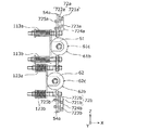
図4は、本実施の形態に係るスタッカクレーン50のフェイスローラ61、62及び63並びにストッパ73a及び73bの構成の概要を示す断面図である。
FIG. 4 is a cross-sectional view showing an outline of the configuration of the
図5は、本実施の形態に係る昇降台51のフェイスローラ61に力が加わらない場合におけるフェイスローラ61及び62周辺部の断面図である。
FIG. 5 is a cross-sectional view of the periphery of the
図6は、本実施の形態に係る昇降台51のフェイスローラ62がマスト30aに当接する場合における断面図である。
FIG. 6 is a cross-sectional view in the case where the
図7は、本実施の形態に係る昇降台51のフェイスローラ63が退避位置にある場合における断面図である。
FIG. 7 is a cross-sectional view when the
なお、図4〜7においては、スタッカクレーン50の各フェイスローラの周辺部分だけが示されている。
4 to 7 show only the peripheral portion of each face roller of the
図4に示されるように、本実施の形態に係るスタッカクレーン50の昇降台51は、移載装置52と、本体部53と、縦ビーム54a及び54bと、フェイスローラ61、62及び63と、ストッパ73a及び73bとを備える。なお、図4には示されないが、上述のとおり、昇降台51はフェイスローラ64をさらに備える。
As shown in FIG. 4, the
本体部53は、移載装置52が設けられる部材である。本体部53は、水平方向に延びる平板状の部材であり、その上面に移載装置52が設けられ、X軸方向の両端部に、それぞれ縦ビーム54a及び54bが設けられる。
The
縦ビーム54a及び54bは、それぞれ、本体部53の走行方向(X軸方向)における両端部に立設された部材である。縦ビーム54aには、フェイスローラ61、62及び64が設けられ、縦ビーム54bには、フェイスローラ63及び64、並びに、ストッパ73a及び73bが設けられる。
The
[3−1.フェイスローラ]
続いて、フェイスローラ61、62及び63について説明する。
[3-1. Face roller]
Subsequently, the
まず、フェイスローラ61の構成について説明する。
First, the configuration of the
フェイスローラ61は、移載装置52とマスト30aとの間に配置され、マスト30aの表面である第二当接面31bを転動するフェイスローラである。フェイスローラ61は、その周縁に転動面61bを有し、転動面61bのマスト30a寄りの端部61cにおいてマスト30aと当接する。
The
フェイスローラ61は、マスト30a寄りの突出位置と、当該突出位置より移載装置52寄りの退避位置との間において移動可能である。ここで、フェイスローラ61の突出位置とは、図5に示されるように、フェイスローラ61がマスト30aから力を受けない場合におけるフェイスローラ61の位置である。また、フェイスローラ61の退避位置とは、図6に示されるように、フェイスローラ61及びフェイスローラ62がマスト30aに当接する場合におけるフェイスローラ61の位置である。フェイスローラ61は、マスト30aからX軸方向負向きに力を受けることによって、X軸方向負向きに移動した場合に、退避位置に配置される。
The
フェイスローラ61を構成する材料は、特に限定されない。本実施の形態では、フェイスローラ61を構成する材料として、例えば、ナイロンなどの樹脂が用いられる。
The material which comprises the
図4に示されるように、フェイスローラ61は、スタッドボルト110a、110b、カラー112a、112b、バネ113a、113b、ナット114a、114b、115a、115b、並びに、支持具116を用いて縦ビーム54aに取り付けられている。
As shown in FIG. 4, the
スタッドボルト110a及び110bは、それぞれ、六角部111a及び111bを有する棒ねじである。
The
支持具116は、フェイスローラ61を転動可能な状態で支持する部材である。支持具116の図4における上下方向の各端部には、スタッドボルト110a及び110bを貫通させるための貫通孔が設けられている。
The
カラー112a及び112bは、フェイスローラ61がバネ113a及び113bによって、所定の位置よりマスト30a寄りに移動することを規制する規制部材である。カラー112a及び112bは、それぞれ、スタッドボルト110a及び110bのねじ部が挿入される貫通孔を有する筒状の部材である。カラー112a及び112bの寸法を調整することにより、フェイスローラ61の端部61cからマスト30aの表面までの距離を調整することができる。ここで、バネ113a及び113bの付勢力に基づいて、フェイスローラ61を退避位置に移動させるために必要な力、すなわち、フェイスローラ62をマスト30aに当接させるために必要な力が決定される。したがって、この構成によれば、フェイスローラ62をマスト30aに当接させるために必要な力を調整できる。このため、フェイスローラ61とマスト30aとの当接部に加わる力の大きさを、フェイスローラ61及びマスト30aが変形又は損傷しない程度の大きさに制限できる。
The
バネ113a及び113bは、荷物90を移載する際に、常時、フェイスローラ61をマスト30aに当接させ、かつ、フェイスローラ63をマスト30bに当接させることにより、昇降台51のX軸方向の位置を安定化させるための付勢部材である。そのため、バネ113a及び113bの弾性係数をバネ133a及び133bの弾性係数と同程度に大きくする場合には、各フェイスローラ及び各マストに常にストレスがかかるため、各フェイスローラの損傷及び各マストの変形を引き起こし得る。そこで、バネ113a及び113bの弾性係数は、各フェイスローラの損傷及び各マストの変形が生じない程度に十分に小さく設定されている。
The
以下、フェイスローラ61の縦ビーム54aへの取り付け工程について説明する。
Hereinafter, the process of attaching the
まず、スタッドボルト110a及び110bの、図4における左側の各ねじ部が、それぞれ、カラー112a及び112bの各貫通孔に挿入される。
First, the left threaded portions of the
続いて、スタッドボルト110a及び110bの図4における左側の各ねじ部が、それぞれ、支持具116の図4における上下方向の各端部に設けられた貫通孔に挿入される。なお、支持具116には、フェイスローラ61が取り付けられている。
Subsequently, the left threaded portions of the
続いて、スタッドボルト110a及び110bの図4における左側の各ねじ部が、それぞれ、バネ113a及び113bに挿入された後、各ねじ部にフランジ付きのナット114a及び114bが取り付けられる。ナット114a及び114bが、それぞれ、各ねじ部の所定の位置に配置されるように締め付けられることにより、バネ113a及び113bが縮められる。これにより、バネ113a及び113bが支持具116、すなわち、フェイスローラ61をX軸方向正向き(マスト30a向き)に押す状態が維持される。なお、本実施の形態では、ナット134a及び134bとして緩み止めナットを用いているため、ナット134a及び134bの位置ずれが抑制される。また、ナット134a及び134bとして、それぞれ隣接する二つのナットを用いること(いわゆるダブルナット)によって、ナット134a及び134bの位置ずれを抑制してもよい。
Subsequently, after the respective screw portions on the left side in FIG. 4 of the
続いて、スタッドボルト110a及び110bの図4における右側の各ねじ部が、縦ビーム54aの貫通孔に挿入される。スタッドボルト110aの縦ビーム54aに挿入されたねじ部の端から、ナット115aが装着されることにより、スタッドボルト110aが縦ビーム54aに固定される。スタッドボルト110bについても同様にナット115bによって、縦ビーム54aに固定される。
Subsequently, the screw portions on the right side in FIG. 4 of the
以上のように、フェイスローラ61が、縦ビーム54aに取り付けられる。これにより、フェイスローラ61がマスト30aからバネ113a及び113bを縮めるのに十分な力を受けない場合には、フェイスローラ61は、支持具116を介してバネ113a及び113bによって付勢されることによりマスト30a寄りの位置に配置される。一方、フェイスローラ61がマスト30aからバネ113a及び113bを縮めるのに十分な力を受ける場合には、バネ113a及び113bは、図6に示されるように、フェイスローラ62がマスト30aに当接するまで縮み得る。図6に示されるように、フェイスローラ62がマスト30aに当接した状態におけるフェイスローラ61の位置が退避位置である。
As described above, the
以上に述べたように、フェイスローラ61は、マスト30aから力を受けない場合における突出位置と、突出位置より移載装置52寄りの退避位置との間において移動可能である。また、バネ113a及び113bは、フェイスローラ61を退避位置から突出位置へ向けて付勢する。
As described above, the
続いて、フェイスローラ62の構成について説明する。
Subsequently, the configuration of the
フェイスローラ62は、移載装置52とマスト30aとの間に配置され、マスト30aの表面を転動し得るフェイスローラであって、マスト30a寄りの突出位置と、当該突出位置より移載装置52寄りの退避位置との間において移動可能である。ここで、フェイスローラ62の突出位置とは、図4に示されるように、フェイスローラ62がマスト30aから力を受けない場合におけるフェイスローラ62の位置である。また、フェイスローラ62の退避位置とは、フェイスローラ62が、マスト30aからX軸方向負向きに急激に大きな力を受けて、X軸方向負向きに移動した場合におけるフェイスローラ62の位置である。
The
フェイスローラ62は、図4に示されるように、上述のフェイスローラ61と同様の構成を有する。フェイスローラ62は、その周縁に転動面62bを有する。フェイスローラ62は、フェイスローラ61が退避位置に配置される場合に、転動面62bのマスト30a寄りの端部62cにおいてマスト30aと当接する。この場合、フェイスローラ61の端部61c及びフェイスローラ62の端部62cが、マスト30aの表面である第二当接面31bに当接する。つまり、退避位置に配置されたフェイスローラ61の端部61cとマスト30aの表面である第二当接面31bとの間の距離は、突出位置に配置されたフェイスローラ62の端部62cとマスト30aの表面である第二当接面31bとの間の距離と等しい。
The
なお、フェイスローラ61(及びフェイスローラ62)がマスト30aからX軸方向負向きにさらに力を受けることにより、フェイスローラ61は、当該退避位置からさらに移載装置52寄りの位置に退避し得る。つまり、退避位置に配置されたフェイスローラ61の端部61cとマスト30aの表面である第二当接面31bとの間の距離は、突出位置に配置されたフェイスローラ62の端部62cとマスト30aの表面である第二当接面31bとの間の距離より大きくなり得る。
When the face roller 61 (and the face roller 62) further receives a force from the
フェイスローラ62は、スタッドボルト120a及び120b、カラー122a及び122b、バネ123a及び123b、ナット124a、124b、125a及び125b、並びに、支持具126を用いて縦ビーム54aに取り付けられている。なお、スタッドボルト120a及び120bは、それぞれ、六角部121a及び121bを有する。
The
バネ123a及び123bは、スタッカクレーン50の通常動作時には、実質的に伸縮しない程度に強い弾性力を有し、スタッカクレーン50のマスト30aと昇降台51との間に急激に大きな力が加わった場合にのみ伸縮する。以上のように、バネ123a及び123bの弾性係数は、上述のバネ113a及び113bの弾性係数より大きい。
The
続いて、フェイスローラ61及び62の位置関係について説明する。
Subsequently, the positional relationship between the
図4に示されるように、フェイスローラ61及び62は、それぞれ、マスト30a寄りの端部61c及び62cを有する。フェイスローラ61が突出位置に配置される場合における端部61cからマスト30aの表面である第二当接面31bまでの距離は、端部62cからマスト30aの表面までの距離より小さい。また、フェイスローラ61が退避位置に配置される場合における端部61cからマスト30aの表面までの距離は、端部62cからマスト30aの表面までの距離以上である。
As shown in FIG. 4, the
これにより、例えば、荷物90を移載する場合などのスタッカクレーン50が静止している場合には、図4に示されるように、バネ113a及び113bによって、フェイスローラ61がマスト30aの表面に向けて付勢される。したがって、昇降台51の図4におけるX軸方向の位置が安定化される。一方、昇降台51がX軸方向正向きに力を受ける場合、図6に示されるように、バネ113a及び113bが縮んで、フェイスローラ61及び62がマスト30aに当接する。このように、昇降台51がX軸方向正向きにバネ113a及び113bの弾性力より大きい力を受ける場合、フェイスローラ62がマスト30aに当接する。これにより、フェイスローラ62を付勢するバネ123a及び123bによって、当該力を吸収することができ、フェイスローラ61に加わる力を低減することができる。したがって、フェイスローラ61及びマスト30aの変形及び破損を抑制できる。さらに、この場合にもフェイスローラ61及び62が転動することができるため、昇降台51をスムーズに昇降させることができる。
Thus, for example, when the
続いてフェイスローラ63の構成について説明する。
Subsequently, the configuration of the
フェイスローラ63は、移載装置52とマスト30bとの間に配置され、マスト30bの表面である第二当接面31bを転動する。フェイスローラ63は、その周縁に転動面63bを有し、転動面63bのマスト30b寄りの端部63cにおいてマスト30bと当接する。
The
フェイスローラ63は、マスト30b寄りの突出位置と、当該突出位置より移載装置52寄りの退避位置との間において移動可能である。ここで、フェイスローラ63の突出位置とは、図4に示されるように、通常動作時におけるフェイスローラ63の位置である。また、フェイスローラ63の退避位置とは、図7に示されるように、フェイスローラ63及びストッパ73a及び73bがマスト30bに当接する場合におけるフェイスローラ63の位置である。フェイスローラ63は、マスト30bからX軸方向正向きに力を受けることによって、X軸方向正向きに移動した場合に、退避位置に配置される。
The
フェイスローラ63は、図4に示されるように、上述のフェイスローラ61と同様の構成を有する。図4に示されるように、フェイスローラ63は、スタッドボルト130a、130b、カラー132a、132b、バネ133a、133b、ナット134a、134b、135a、135b、及び、支持具136を用いて縦ビーム54bに取り付けられている。なお、スタッドボルト130a及び130bは、それぞれ、六角部131a及び131bを有する。
The
ただし、上記各取付部材のうち、バネ133a及び133bの弾性係数が、上記のバネ113a及び113bと異なる。上述のとおり、バネ113a及び113bの弾性係数は、各マストが変形しない程度に、かつ、フェイスローラ61が損傷しない程度に十分に小さく設定されている。一方、バネ133a及び133bは、スタッカクレーン50の通常動作時には、実質的に伸縮しない程度に強い弾性力を有し、スタッカクレーン50のマスト30bと昇降台51との間に急激に大きな力が加わった場合にのみ伸縮する。本実施の形態では、バネ133a及び133bの弾性係数は、バネ113a及び113bの弾性係数より大きく、バネ123a及び123bの弾性係数と同程度である。
However, among the attachment members, the elastic coefficients of the
以上のように、フェイスローラ61、62及び63が構成されることにより、スタッカクレーン50の走行台車20が停止している場合には、フェイスローラ61は、バネ113a及び113bによって付勢されることにより、マスト30aに当接する。また、この場合、フェイスローラ63は、バネ113a及び113bによってマスト30b向きに付勢されることにより、マスト30bに当接する。ここで、フェイスローラ63を付勢するバネ133a及び133bは、それぞれ、カラー132a及び132bと、ナット134a及び134bとにより、所定の長さより長くならないように規制されている。また、バネ133a及び133bは、バネ113a及び113bより十分強い力でフェイスローラ63を付勢しているため、実質的に縮まない。このため、フェイスローラ63は、突出位置に配置された状態で、バネ113a及び113bによって、マスト30b向きに付勢される。以上のように、フェイスローラ61と移載装置52との相対位置は、両マスト間の間隔の変化に応じて変動するが、フェイスローラ63と移載装置52との相対位置はほぼ変動しない。したがって、この構成によれば、フェイスローラ63と移載装置52との相対位置を安定化させることができる。ここで、フェイスローラ63は、マスト30bに当接しているため、移載装置52のマスト30bに対する相対位置を安定化させることができる。これにより、荷物90の移載位置を安定化させることができる。
As described above, when the traveling
また、走行台車20が走行する場合には、バネ113a及び113bの付勢力より、走行台車20の加減速により昇降台51に加わる力の方が大きくなることがある。走行台車の加減速により、バネ113a及び113bが縮む向き(X軸方向正向き)に昇降台51に力が加わる場合には、フェイスローラ62がマスト30aに当接し、かつ、転動することにより、昇降台51をスムーズに昇降させることができる。一方、走行台車20の加減速により、バネ113a及び113bが延びる向き(X軸方向負向き)に昇降台51に力が加わる場合には、フェイスローラ63がマスト30bに当接し、かつ、転動することにより、昇降台51をスムーズに昇降させることができる。
In addition, when the traveling
また、本実施の形態では、バネ113a及び113bがフェイスローラ61を付勢する力が、走行台車20の加減速による力より小さいので、各マスト及び各フェイスローラに常時加わる力を抑制することができる。
Further, in the present embodiment, since the force by which the
また、本実施の形態では、昇降台51とマスト30aとの間に加わる力は、二つのフェイスローラ61及び62に分散され得る。したがって、昇降台51とマスト30bとの間に配置されたフェイスローラ63より、フェイスローラ61及び62に加わる力は低減され得る。これにより、フェイスローラ61及び62は、フェイスローラ63ほど頑丈でなくてもよい。例えば、フェイスローラ61及び62の径は、フェイスローラ63の径より小さくてもよい。
Further, in the present embodiment, the force applied between the
[3−2.ストッパ]
続いて、ストッパ73a及び73bについて説明する。
[3-2. Stopper]
Subsequently, the
ストッパ73a及び73bは、移載装置52とマスト30bとの間に配置され、それぞれ、マスト30bに対向する対向部734a及び734bを有する部材である。ストッパ73a及び73bは、昇降台51に対して、X軸方向の負向きに急激な力が加わった場合に、マスト30bに当接することによって、フェイスローラ63とマスト30bとの当接部に加わる力を抑制する。
The
X軸方向の負向きに急激な力が加わる場合とは、例えば、スタッカクレーン50が、X軸方向の負向きに走行している際に、下部レール12の端部に減速することなく衝突する場合などが想定される。一般に、下部レール12の端部には、衝突時の衝撃を吸収するショックアブソーバが設けられるが、スタッカクレーン50が減速することなく、下部レール12の端部に衝突する場合には、非常に大きな力が、マスト30bと、昇降台51との間に加わる。
When a rapid force is applied in the negative direction in the X-axis direction, for example, when the
対向部734a及び734bからマスト30bの表面(第二当接面31b)までの距離は、フェイスローラ63が突出位置に配置される場合におけるフェイスローラ63のマスト30b寄りの端部63cからマスト30bの表面までの距離より大きい。一方、対向部734a及び734bからマスト30bの表面までの距離は、フェイスローラ63が退避位置に配置される場合における端部63cからマスト30bの表面までの距離以下である。
The distance from the facing
図4に示されるように、ストッパ73aは、当接部材731a及び取付部材732aから構成され、縦ビーム54bに設けられる。
As shown in FIG. 4, the
取付部材732aは、当接部材731aを縦ビーム54bに取り付けるための部材である。取付部材732aには、ねじ穴が設けられており、取付部材732aは縦ビーム54bの貫通孔を貫通させたボルト735aが捻じ込まれることにより、縦ビーム54bに取り付けられる。
The
当接部材731aは、ストッパ73aのマスト30b寄りに配置された部材であり、マスト30bと対向する対向部734aを備える。本実施の形態では、対向部734aは、フェイスローラ63が転動するマスト30bの表面である第二当接面31bと略平行な平坦面を有する。これにより、対向部734aとマスト30bとの接触面積を増大させることができるため、フェイスローラ63とマスト30bとの間に加わる力をより広い接触面に分散させることができる。
The
当接部材731aは、取付部材732aに取り付けられている。当接部材731aの取付部材732aへの取付構成は特に限定されない。本実施の形態では、当接部材731aに図4のX軸方向に座ぐり孔が形成されている。当接部材731aの座ぐり孔の対向部734a側から取付部材732aに向けてボルト733aが挿入され、ボルト733aが取付部材732aに形成されたねじ穴に捻じ込まれる。これにより、対向部734aにボルト733aの頭部を突出させることなく、当接部材731aを取付部材732aに取り付けることができる。
The
当接部材731aを構成する材料は、特に限定されない。本実施の形態では、当接部材731aを構成する材料として、例えば、ナイロンなどの樹脂が用いられる。
The material which comprises the
ストッパ73bも、ストッパ73aと同様に当接部材731b及び取付部材732bから構成される。取付部材732bは、取付部材732aと同様の構成を有し、ボルト735bを用いて縦ビーム54bに取り付けられる。また、当接部材731bは、当接部材731aと同様の構成を有し、ボルト733bを用いて取付部材732bに取り付けられる。
Similarly to the
以上のように、フェイスローラ63と、ストッパ73a及び73bとが構成されることにより、スタッカクレーン50の通常動作時には、フェイスローラ63が、端部63cにおいて、マスト30bの第二当接面31bに当接しながら転動する。これにより、マスト30bと昇降台51との間の接触抵抗を低減することができる。なお、フェイスローラ63は、必ずしも常にマスト30bの第二当接面31bと当接している必要はない。昇降台51が、マスト30bから離れる方向に力を受ける場合には、フェイスローラ63は、マスト30bから離れてもよい。一方、スタッカクレーン50のフェイスローラ63とマスト30bとの間に、スタッカクレーン50の走行方向(X軸方向)に急激に力が加わる場合には、フェイスローラ63が退避位置に移動する。このため、昇降台51とマスト30bとは、フェイスローラ63並びにストッパ73a及び73bにおいて当接する。したがって、昇降台51とマスト30bとの間に加わる力が、ストッパ73a及び73bにも分散されるため、フェイスローラ63及びマスト30bの少なくとも一方が変形又は破損することを抑制できる。
As described above, by configuring the
また、本実施の形態では、ストッパ73a及び73bは、それぞれ、フェイスローラ63の上方及び下方に設けられる。これにより、昇降台51とマスト30bとの間に加わる力が、上方のストッパ73a及び下方のストッパ73bの両方に分散されるため、ストッパを一つだけ設ける場合より、各ストッパ及びフェイスローラ63に加わる力が低減される。さらに、ストッパ73a及び73bがフェイスローラ63の上方及び下方に設けられることにより、ストッパがフェイスローラ63の上方又は下方の一方だけに設けられる場合と比べて、縦ビーム54bがマスト30bに対して傾くことが抑制される。このため、縦ビーム54bの変形及び昇降台51の姿勢の傾きを抑制することができる。
Further, in the present embodiment, the
また、上述のとおり、ストッパ73a及び74bは、フェイスローラ63を保持する縦ビーム54bに設けられるため、昇降台51は、ストッパ73a及び73bを設けるための部材を別途備えなくてもよい。このため昇降台51の構成を簡素化することができる。これに伴い、スタッカクレーン50の軽量化及び低コスト化が可能となる。
Further, as described above, since the
(変形例)
続いて、上記実施の形態に係るスタッカクレーン50の変形例について説明する。上記実施の形態では、マスト30b側だけにストッパ73a及び73bが設けられたが、本変形例では、図8に示されるようにストッパ73a及び73bと同様の構成を有するストッパがマスト30a側にも設けられる。
(Modification)
Then, the modification of
図8は、本変形例に係るスタッカクレーンのフェイスローラ61及び62周辺部における断面図である。
FIG. 8 is a cross-sectional view of the periphery of the
図9は、変形例に係るスタッカクレーン50のフェイスローラ62が退避位置にある場合の断面図である。
FIG. 9 is a cross-sectional view of the
図8に示されるように、本変形例では、フェイスローラ61及び62の上方にストッパ72aが設けられ、フェイスローラ61及び62の下方にストッパ72bが設けられている。
As shown in FIG. 8, in the present modification, a
ストッパ72a及び72bは、移載装置52とマスト30aとの間に配置され、それぞれ、マスト30aに対向する対向部724a及び724bを有する部材である。ストッパ72a及び72bは、昇降台51に対して、X軸方向の正向きに急激な力が加わった場合に、図9に示されるようにマスト30aに当接することによって、フェイスローラ61及び62とマスト30aとの当接部に加わる力を抑制する。
The
対向部724a及び724bからマスト30aの表面(第二当接面31b)までの距離は、フェイスローラ62が突出位置に配置される場合におけるフェイスローラ62のマスト30a寄りの端部62cからマスト30aの表面までの距離より大きい。一方、対向部724a及び724bからマスト30aの表面までの距離は、フェイスローラ62が退避位置に配置される場合における端部62cからマスト30aの表面までの距離以下である。なお、ここで、フェイスローラ62の突出位置とは、フェイスローラ62がマスト30aから力を受けない場合の位置である。また、フェイスローラ62の退避位置とは、対向部724a及び724bがマスト30aに当接する場合のフェイスローラ62の位置である。フェイスローラ62は、マスト30aからX軸方向負向きに急激に力を受けることにより、退避位置に移動する。
The distance from the facing
ストッパ72aは、ストッパ73a及び73bと同様に、当接部材721a及び取付部材722aから構成され、縦ビーム54aに設けられる。
Similar to the
当接部材721aの対向部724aは、フェイスローラ61及び62が転動するマスト30aの表面である第二当接面31bと略平行な平坦面を有する。これにより、対向部724aとマスト30aとの接触面積を増大させることができるため、フェイスローラ61及び62とマスト30aとの間に加わる力をより広い接触面に分散させることができる。
The facing
また、取付部材722aは、取付部材732a及び732bと同様の構成を有し、ボルト725aを用いて縦ビーム54aに取り付けられる。また、当接部材721aは、当接部材731a及び731bと同様の構成を有し、ボルト723aを用いて取付部材722aに取り付けられる。
Also, the
ストッパ72bは、ストッパ72aと同様に、当接部材721b及び取付部材722bから構成され、縦ビーム54aに設けられる。
Similar to the
当接部材721bは、マスト30aと対向する対向部724bを備える。本実施の形態では、対向部724bは、フェイスローラ61及び62が転動するマスト30aの表面である第二当接面31bと略平行な平坦面を有する。これにより、対向部724bとマスト30aとの接触面積を増大させることができるため、フェイスローラ61及び62とマスト30aとの間に加わる力をより広い接触面に分散させることができる。
The abutment member 721b includes an opposing
また、取付部材722bは、取付部材722aと同様の構成を有し、ボルト725bを用いて縦ビーム54aに取り付けられる。また、当接部材721bは、当接部材721aと同様の構成を有し、ボルト723bを用いて取付部材722bに取り付けられる。
Also, the
本変形例に係るスタッカクレーンは、以上の構成を有することにより、通常動作時には、フェイスローラ61、又は、フェイスローラ61及び62が、マスト30aの第二当接面31bに当接しながら転動する。これにより、マスト30aと昇降台51との間の接触抵抗を低減することができる。一方、スタッカクレーン50のフェイスローラ62とマスト30aとの間に、スタッカクレーン50の走行方向(X軸方向)に急激に力が加わる場合には、フェイスローラ61及び62が退避位置に移動する。これにより、昇降台51とマスト30aとは、フェイスローラ61及び62並びにストッパ72a及び72bにおいて当接する。したがって、昇降台51とマスト30aとの間に加わる力が、ストッパ72a及び72bにも分散されるため、フェイスローラ61、62及びマスト30aの少なくとも一つが変形又は破損することを抑制できる。
In the stacker crane according to the present modification, the
(その他の変形例など)
以上、本発明の搬送車システム及びその制御方法について、実施の形態に基づいて説明した。しかしながら、本発明は、上記の各実施形態に限定されるものではない。本発明の趣旨を逸脱しない限り、当業者が思いつく各種変形を実施形態に施したものも、あるいは、上記説明された複数の構成要素を組み合わせて構築される形態も、本発明の範囲内に含まれる。
(Other modifications etc.)
The carrier system and the control method thereof according to the present invention have been described above based on the embodiments. However, the present invention is not limited to the above embodiments. Without departing from the spirit of the present invention, various modifications apparent to those skilled in the art may be made to the embodiment, or a form constructed by combining the plurality of components described above is included within the scope of the present invention. Be
例えば、上記実施の形態では、対向部734a及び734bは、第二当接面31bと略平行な平坦面を有するが、対向部734a、734bの構成はこれに限定されない。対向部734a、734bは、マスト30aの第二当接面31bと当接し得る構成であればよい。
For example, in the above embodiment, the facing
また、上記実施の形態では、各ストッパは、当接部材と取付部材とから構成されたが、ストッパの構成はこれに限定されない。例えば、ストッパは、当接部材だけから構成されてもよい。 Moreover, in the said embodiment, although each stopper was comprised from the contact member and the attachment member, the structure of a stopper is not limited to this. For example, the stopper may be composed of only the contact member.
また、上記実施の形態では、各ストッパは縦ビームに設けられたが、昇降台51の縦ビーム以外の構成要素に設けられてもよい。また、上記実施の形態では、ストッパは縦ビームにボルトなどを用いて取り付けられたが、ストッパの取付構成は特に限定されない。例えば、ストッパは接着剤などを用いて取り付けられてもよい。
Moreover, in the said embodiment, although each stopper was provided in the vertical beam, you may be provided in components other than the vertical beam of the raising / lowering
また、上記実施の形態では、ストッパは、フェイスローラの上方及び下方に設けられたが、ストッパは必ずしも、上方及び下方の両方に設けられなくてもよい。例えば、フェイスローラの上方及び下方のいずれか一方だけに設けられてもよい。 In the above embodiment, the stoppers are provided above and below the face roller, but the stoppers may not necessarily be provided both above and below. For example, only one of the upper and lower sides of the face roller may be provided.
また、上記実施の形態に係るスタッカクレーンは、二本のマストを備える構成を有したが、本発明の一態様に係るスタッカクレーンは、マストを一本だけ備える構成を有してもよい。例えば、スタッカクレーンの一本のマストの対向する二つの表面(スタッカクレーンの走行方向における両端の表面)の各々に一組以上のフェイスローラ61及び62並びにストッパ72a及び72bを設けてもよい。これにより、上記実施の形態と同様の効果を奏するスタッカクレーンを実現することができる。
Moreover, although the stacker crane which concerns on the said embodiment had a structure provided with two masts, the stacker crane which concerns on 1 aspect of this invention may have a structure provided with only one mast. For example, one or more sets of
本発明のスタッカクレーンは、フェイスローラを備える昇降台と、当該フェイスローラが当接するマストを備え、当該フェイスローラ及びマストの変形及び破損を抑制できるスタッカクレーンである。従って、工場及び物流倉庫等で荷物の搬送を行うスタッカクレーン等として有用である。 The stacker crane according to the present invention is a stacker crane that includes a lifting platform provided with a face roller and a mast with which the face roller abuts, so that deformation and breakage of the face roller and the mast can be suppressed. Therefore, it is useful as a stacker crane etc. which conveys a load in a factory, a distribution warehouse, etc.
12 下部レール
20 走行台車
30a、30b マスト
31 ローラ当接部材
31a 第一当接面
31b 第二当接面(表面)
35 裏側部材
40 連結部材
41 第一連結面部
42 第二連結面部
50 スタッカクレーン
51 昇降台
52 移載装置
53 本体部
54a、54b 縦ビーム
58 ステーション
60 締結部材
61、62、63、64 フェイスローラ
61a、63a、64a 回転軸
61b、62b、63b 転動面
61c、62c、63c 端部
72a、72b、73a、73b ストッパ
80 ラック
90 荷物
100 自動倉庫
110a、110b、120a、120b、130a、130b スタッドボルト
111a、111b、121a、121b、131a、131b 六角部
112a、112b、122a、122b、132a、132b カラー(規制部材)
113a、113b、123a、123b、133a、133b バネ(付勢部材)
114a、114b、115a、115b、124a、124b、125a、125b、134a、134b、135a、135b ナット
116、126、136 支持具
721a、721b、731a、731b 当接部材
722a、722b、732a、732b 取付部材
724a、724b、734a、734b 対向部
723a、723b、725a、725b、733a、733b、735a、735b ボルト
12
35 back
113a, 113b, 123a, 123b, 133a, 133b Springs (biasing members)
114a, 114b, 115a, 115b, 124a, 124b, 125a, 125b, 134a, 134b, 135a, 135b
Claims (4)
昇降台と、
前記昇降台をガイドする第一のマストと、を備え、
前記昇降台は、
前記ラックとの間で荷物を移載する移載装置と、
前記移載装置と前記第一のマストとの間に配置され、前記第一のマストの第一の表面を転動する第一のフェイスローラであって、前記第一のマスト寄りの第一の突出位置と、前記第一の突出位置より前記移載装置寄りの第一の退避位置との間において移動可能な第一のフェイスローラと、
前記第一のフェイスローラを前記第一の退避位置から前記第一の突出位置へ向けて付勢する第一の付勢部材と、
前記移載装置と前記第一のマストとの間に配置された第二のフェイスローラとを備え、
前記第一のフェイスローラは、前記第一のマスト寄りの第一の端部を有し、
前記第二のフェイスローラは、前記第一のマスト寄りの第二の端部を有し、
前記第一のフェイスローラが前記第一の突出位置に配置される場合における前記第一の端部から前記第一の表面までの距離は、前記第二の端部から前記第一の表面までの距離より小さく、かつ、前記第一のフェイスローラが前記第一の退避位置に配置される場合における前記第一の端部から前記第一の表面までの距離は、前記第二の端部から前記第一の表面までの距離以上である
スタッカクレーン。 A stacker crane traveling on a track arranged along a rack,
Lifting platform,
And a first mast for guiding the lifting platform.
The elevator platform is
A transfer device for transferring a load between the rack and the rack;
A first face roller disposed between the transfer device and the first mast and rolling on a first surface of the first mast, the first face roller being closer to the first mast A first face roller movable between a projecting position and a first retracted position closer to the transfer device than the first projecting position;
A first biasing member for biasing the first face roller from the first retracted position toward the first projecting position;
A second face roller disposed between the transfer device and the first mast;
The first face roller has a first end closer to the first mast,
The second face roller has a second end closer to the first mast,
The distance from the first end to the first surface when the first face roller is disposed at the first projecting position is the distance from the second end to the first surface The distance from the first end to the first surface when the first face roller is smaller than the distance and the first face roller is disposed at the first retracted position is the distance from the second end to the first surface. More than the distance to the first surface Stacker crane.
前記昇降台は、
前記第二のフェイスローラを前記第二の退避位置から前記第二の突出位置へ向けて、前記第一の付勢部材より強い力で付勢する第二の付勢部材と、
前記移載装置と前記第一のマストとの間に配置され、前記第一のマストに対向する第一の対向部を有する第一のストッパとをさらに備え、
前記第二のフェイスローラが前記第二の突出位置に配置される場合における前記第二の端部から前記第一の表面までの距離は、前記第一の対向部から前記第一の表面までの距離より小さく、かつ、前記第二のフェイスローラが前記第二の退避位置に配置される場合における前記第二の端部から前記第一の表面までの距離は、前記第一の対向部から前記第一の表面までの距離以上である
請求項1に記載のスタッカクレーン。 The second face roller is movable between a second projecting position closer to the first mast and a second retracted position closer to the transfer device than the second projecting position,
The elevator platform is
A second biasing member that biases the second face roller from the second retracted position toward the second projecting position with a stronger force than the first biasing member;
And a first stopper disposed between the transfer device and the first mast and having a first facing portion facing the first mast.
The distance from the second end to the first surface when the second face roller is disposed at the second projecting position is the distance from the first opposing portion to the first surface The distance from the second end to the first surface when the second face roller is smaller than the distance and the second face roller is disposed at the second retracted position is the distance from the first opposing portion to the first surface. The stacker crane according to claim 1, which is equal to or more than the distance to the first surface.
前記第二のマストは、前記昇降台に対して、前記第一のマストの反対側に配置され、
前記昇降台は、
前記移載装置と前記第二のマストとの間に配置され、前記第二のマストの第二の表面を転動する第三のフェイスローラであって、前記第二のマスト寄りの第三の突出位置と、前記第三の突出位置より前記移載装置寄りの第三の退避位置との間において移動可能であり、かつ、前記第一のフェイスローラより径の大きい第三のフェイスローラと、
前記第三のフェイスローラを前記第三の退避位置から前記第三の突出位置へ向けて前記第一の付勢部材より強い力で付勢する第三の付勢部材とを備える
請求項1又は2に記載のスタッカクレーン。 The stacker crane further includes a second mast for guiding the elevator platform,
The second mast is disposed opposite to the first mast with respect to the lift platform,
The elevator platform is
A third face roller disposed between the transfer device and the second mast and rolling on a second surface of the second mast, wherein the third face roller is closer to the second mast. A third face roller movable between a projecting position and a third retracted position closer to the transfer device than the third projecting position, and having a diameter larger than the first face roller;
A third biasing member for biasing the third face roller from the third retracted position toward the third projecting position with a force stronger than the first biasing member. The stacker crane according to 2.
前記第三のフェイスローラが前記第三の突出位置に配置される場合における前記第三のフェイスローラの前記第二のマスト寄りの第三の端部から前記第二の表面までの距離は、前記第二の対向部から前記第二の表面までの距離より小さく、かつ、前記第三のフェイスローラが前記第三の退避位置に配置される場合における前記第三の端部から前記第二の表面までの距離は、前記第二の対向部から前記第二の表面までの距離以上である
請求項3に記載のスタッカクレーン。 The elevator platform further includes a second stopper disposed between the transfer device and the second mast and having a second facing portion facing the second mast.
When the third face roller is disposed at the third projecting position, the distance from the third end of the third face roller closer to the second mast to the second surface is The distance from the second end to the second surface, and the third end to the second surface when the third face roller is disposed at the third retraction position The stacker crane according to claim 3, wherein a distance between the second facing portion and the second surface is equal to or greater than a distance between the second facing portion and the second surface.
Priority Applications (1)
| Application Number | Priority Date | Filing Date | Title |
|---|---|---|---|
| JP2015163233A JP6536282B2 (en) | 2015-08-20 | 2015-08-20 | Stacker crane |
Applications Claiming Priority (1)
| Application Number | Priority Date | Filing Date | Title |
|---|---|---|---|
| JP2015163233A JP6536282B2 (en) | 2015-08-20 | 2015-08-20 | Stacker crane |
Publications (2)
| Publication Number | Publication Date |
|---|---|
| JP2017039595A JP2017039595A (en) | 2017-02-23 |
| JP6536282B2 true JP6536282B2 (en) | 2019-07-03 |
Family
ID=58202877
Family Applications (1)
| Application Number | Title | Priority Date | Filing Date |
|---|---|---|---|
| JP2015163233A Active JP6536282B2 (en) | 2015-08-20 | 2015-08-20 | Stacker crane |
Country Status (1)
| Country | Link |
|---|---|
| JP (1) | JP6536282B2 (en) |
Family Cites Families (7)
| Publication number | Priority date | Publication date | Assignee | Title |
|---|---|---|---|---|
| DE9105077U1 (en) * | 1991-04-25 | 1991-07-11 | Keuro Maschinenbau Gmbh & Co Kg, 7590 Achern | Storage and retrieval machine in the form of a gantry crane for a material warehouse for rod-shaped material |
| JPH0712317U (en) * | 1993-07-27 | 1995-02-28 | 小松フォークリフト株式会社 | Vibration control device |
| JPH09124283A (en) * | 1995-10-30 | 1997-05-13 | Toyota Autom Loom Works Ltd | Carriage mounting structure for crane device |
| JPH11208819A (en) * | 1998-01-29 | 1999-08-03 | Okamura Corp | Stacker crane |
| CN2861087Y (en) * | 2005-09-14 | 2007-01-24 | 深圳怡丰自动化停车设备有限公司 | Automation three-D storehouse for board |
| JP5105174B2 (en) * | 2008-02-28 | 2012-12-19 | 株式会社ダイフク | Article conveying device |
| CN104520211B (en) * | 2012-09-04 | 2017-06-09 | 村田机械株式会社 | stacking crane |
-
2015
- 2015-08-20 JP JP2015163233A patent/JP6536282B2/en active Active
Also Published As
| Publication number | Publication date |
|---|---|
| JP2017039595A (en) | 2017-02-23 |
Similar Documents
| Publication | Publication Date | Title |
|---|---|---|
| CN113365930B (en) | Shelf warehouse system with improved load handling unit | |
| CN104520211B (en) | stacking crane | |
| US9296559B2 (en) | Automated warehouse rack | |
| US10351343B2 (en) | Shuttle warehouse | |
| RU2550785C1 (en) | Damping system for crane loading device | |
| US20170327362A1 (en) | Industrial truck comprising a device for reducing vibrations | |
| WO2025050805A1 (en) | Rail apparatus for three-dimensional warehouse stacker and stacker system | |
| JP6536282B2 (en) | Stacker crane | |
| JP6753040B2 (en) | Stacker crane | |
| JP6392067B2 (en) | Nuclear fuel storage facility and nuclear fuel storage method | |
| JP2013123965A (en) | Overturning prevention device for rail traveling machine | |
| US10315890B2 (en) | Arrangement for damping oscillation of loading member in crane | |
| CN215623370U (en) | Material frame | |
| CN112519819B (en) | Bogie and rail vehicle | |
| JP3600554B2 (en) | Seismic isolation device for rail traveling type cargo handling machine | |
| JP2012250821A (en) | Elevator | |
| CN207017894U (en) | Anticollision door | |
| KR200204511Y1 (en) | Device for preventing the friction of wheel flange at crane | |
| CN220221882U (en) | Pallet goods shelves with buffer unit | |
| CN222272078U (en) | A shelf vehicle for storage and transportation of aircraft engine parts | |
| JP6258117B2 (en) | Seismic isolation performance maintaining method | |
| KR102896132B1 (en) | Car component loading and carrying vehicle having improved stability and carrying easy | |
| JP2020011835A (en) | Guide mechanism of lifting device | |
| CN219215028U (en) | Transfer car (buggy) with safety buffer stop | |
| JP6399868B2 (en) | Seismic isolation system for automatic warehouse racks |
Legal Events
| Date | Code | Title | Description |
|---|---|---|---|
| A621 | Written request for application examination |
Free format text: JAPANESE INTERMEDIATE CODE: A621 Effective date: 20180621 |
|
| A977 | Report on retrieval |
Free format text: JAPANESE INTERMEDIATE CODE: A971007 Effective date: 20190412 |
|
| TRDD | Decision of grant or rejection written | ||
| A01 | Written decision to grant a patent or to grant a registration (utility model) |
Free format text: JAPANESE INTERMEDIATE CODE: A01 Effective date: 20190507 |
|
| A61 | First payment of annual fees (during grant procedure) |
Free format text: JAPANESE INTERMEDIATE CODE: A61 Effective date: 20190520 |
|
| R150 | Certificate of patent or registration of utility model |
Ref document number: 6536282 Country of ref document: JP Free format text: JAPANESE INTERMEDIATE CODE: R150 |
|
| R250 | Receipt of annual fees |
Free format text: JAPANESE INTERMEDIATE CODE: R250 |
|
| R250 | Receipt of annual fees |
Free format text: JAPANESE INTERMEDIATE CODE: R250 |