JP6531408B2 - Lighting unit - Google Patents

Lighting unit Download PDF

Info

Publication number
JP6531408B2
JP6531408B2 JP2015016624A JP2015016624A JP6531408B2 JP 6531408 B2 JP6531408 B2 JP 6531408B2 JP 2015016624 A JP2015016624 A JP 2015016624A JP 2015016624 A JP2015016624 A JP 2015016624A JP 6531408 B2 JP6531408 B2 JP 6531408B2
Authority
JP
Japan
Prior art keywords
reflector
case
substrate
row
light emitting
Prior art date
Legal status (The legal status is an assumption and is not a legal conclusion. Google has not performed a legal analysis and makes no representation as to the accuracy of the status listed.)
Active
Application number
JP2015016624A
Other languages
Japanese (ja)
Other versions
JP2016143481A (en
Inventor
友路 佐竹
友路 佐竹
彰 浅野
彰 浅野
智輝 新田
智輝 新田
Current Assignee (The listed assignees may be inaccurate. Google has not performed a legal analysis and makes no representation or warranty as to the accuracy of the list.)
Nichia Corp
Original Assignee
Nichia Corp
Priority date (The priority date is an assumption and is not a legal conclusion. Google has not performed a legal analysis and makes no representation as to the accuracy of the date listed.)
Filing date
Publication date
Application filed by Nichia Corp filed Critical Nichia Corp
Priority to JP2015016624A priority Critical patent/JP6531408B2/en
Publication of JP2016143481A publication Critical patent/JP2016143481A/en
Application granted granted Critical
Publication of JP6531408B2 publication Critical patent/JP6531408B2/en
Active legal-status Critical Current
Anticipated expiration legal-status Critical

Links

Images

Description

本発明は、発光素子を有する照明ユニットに関し、例えば、冷蔵・冷凍食品等をはじめとして、各種商品が陳列されるショーケース用の照明ユニットに関する。   The present invention relates to a lighting unit having a light emitting element, and, for example, to a lighting unit for a showcase in which various products such as refrigerated and frozen foods are displayed.

ショーケース用の照明ユニットとして、一方向に延長したケース内に、発光素子が実装された支持体と、発光素子からの光を反射する光反射体と、が挿入された照明ユニットが提案されている(特許文献1)。   As a lighting unit for a showcase, a lighting unit has been proposed in which a support on which a light emitting element is mounted and a light reflector that reflects light from the light emitting element are inserted in a case extended in one direction. (Patent Document 1).

特開2010−170847号Unexamined-Japanese-Patent No. 2010-170847

特許文献1に記載の照明ユニットにおいて、外部からの衝撃などによって光反射体の位置がずれてしまうと、発光素子から外部に出射される光の光学特性が悪化する恐れがある。特許文献1に記載の照明ユニットの光反射体は、延長方向の一方の端部が支持体に固定され、他方の端部はどこにも固定されていない構成であるため、外部からの衝撃に対する耐性に改善の余地がある。   In the illumination unit described in Patent Document 1, when the position of the light reflector is shifted due to an external impact or the like, the optical characteristics of light emitted from the light emitting element to the outside may be deteriorated. The light reflector of the lighting unit described in Patent Document 1 has a configuration in which one end in the extension direction is fixed to the support and the other end is not fixed anywhere, so that it is resistant to external impact. There is room for improvement.

本発明はかかる事情を鑑みてなされたものであり、衝撃に強く、光学特性が悪化しない照明ユニットを提供する。   The present invention has been made in view of such circumstances, and provides a lighting unit that is resistant to impact and does not deteriorate the optical characteristics.

本発明の一態様に係る照明ユニットは、一方向に延長するケースと、ケース内に配置され、一方向に延長する基板と、ケース内に配置され、基板の表面に配置された複数の発光素子と、ケース内に配置され、一方向に延長し、複数の発光素子からの光を反射するリフレクタと、を有し、複数の発光素子は、一方向に配列された第1列と第2列とを有し、リフレクタは、第1列と第2列との間に位置する底部と、底部から第1列の前方を覆う第1反射部と、底部から第2列の前方を覆う第2反射部と、を有し、リフレクタの第1反射部側と第2反射部側との端部がケースを押圧し、リフレクタの底部が基板を押圧する。   A lighting unit according to one aspect of the present invention includes a case extending in one direction, a substrate disposed in the case, a substrate extending in one direction, and a plurality of light emitting elements disposed in the case and disposed on the surface of the substrate And a reflector disposed in the case and extending in one direction and reflecting light from the plurality of light emitting elements, wherein the plurality of light emitting elements are arranged in one direction, the first row and the second row And the reflector has a bottom portion between the first row and the second row, a first reflecting portion covering the front of the first row from the bottom portion, and a second portion covering the front of the second row from the bottom portion The end portions of the reflector on the first reflection portion side and the second reflection portion side press the case, and the bottom portion of the reflector presses the substrate.

本発明の一態様に係る照明ユニットによれば、所望の光学特性を維持することができる。   According to the lighting unit according to one aspect of the present invention, desired optical characteristics can be maintained.

本実施形態に係る照明ユニットを模式的に示す斜視図である。It is a perspective view showing typically the lighting unit concerning this embodiment. 図1の照明ユニットの下方端を拡大した分解斜視図である。It is the disassembled perspective view which expanded the lower end of the lighting unit of FIG. 本実施形態に係る照明ユニットの基板の平面図である。It is a top view of the substrate of the lighting unit concerning this embodiment. 図1のA−Aの断面図である。It is sectional drawing of AA of FIG.

以下、図面を参照しながら、本実施形態に係る照明ユニットについて説明する。ただし、以下に示す形態は、本発明の技術思想を具体化するためのものであって、本発明を以下のものに特定しない。各図面が示す部材のサイズや位置関係等は、説明を明確にするため誇張していることがある。さらに以下の説明において、同一の名称、符号については、原則として同一もしくは同質の部材を示しており、詳細説明を適宜省略する。   Hereinafter, the illumination unit according to the present embodiment will be described with reference to the drawings. However, the form shown below is for embodying the technical thought of this invention, and does not specify this invention as the following. The size and positional relationship of members shown in each drawing may be exaggerated for the sake of clarity. Further, in the following description, the same names and reference numerals indicate the same or the same members in principle, and the detailed description will be appropriately omitted.

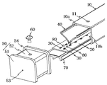
本実施形態に係る照明ユニット100について、図1〜図4を参照して説明する。図1は、本実施形態に係る照明ユニットを模式的に示す斜視図である。図2は、図1の照明ユニットの下方端を拡大した分解斜視図である。図3は、本実施形態に係る照明ユニットの基板の平面図である。図4は、図1の照明ユニットのA−Aの断面図である。   The illumination unit 100 according to the present embodiment will be described with reference to FIGS. 1 to 4. FIG. 1 is a perspective view schematically showing a lighting unit according to the present embodiment. FIG. 2 is an exploded perspective view enlarging the lower end of the lighting unit of FIG. FIG. 3 is a plan view of a substrate of the illumination unit according to the present embodiment. FIG. 4 is a cross-sectional view taken along line A-A of the lighting unit of FIG.

本実施形態に係る照明ユニット100は、一方向に延長するケース10と、ケース10内に配置され、一方向に延長する基板20と、ケース10内に配置され、基板20の表面に配置された複数の発光素子30と、ケース10内に配置され、一方向に延長し、複数の発光素子30からの光を反射するリフレクタ40と、を有する。そして、複数の発光素子30は、一方向に配列された第1列30aと第2列30bとを有する。リフレクタ40は、第1列30aと第2列30bとの間に位置する底部41と、底部41から第1列30aの前方を覆う第1反射部42と、底部41から第2列30bの前方を覆う第2反射部43と、を有し、リフレクタ40の第1反射部42側と第2反射部43側との端部44がケース10を押圧し、リフレクタ40の底部41が基板20を押圧する。   The lighting unit 100 according to the present embodiment is disposed in the case 10 extending in one direction, in the case 10, the substrate 20 extending in one direction, disposed in the case 10, and arranged on the surface of the substrate 20. A plurality of light emitting elements 30 and a reflector 40 disposed in the case 10 and extending in one direction and reflecting light from the plurality of light emitting elements 30 are provided. The plurality of light emitting elements 30 have a first row 30a and a second row 30b arranged in one direction. The reflector 40 has a bottom 41 located between the first row 30a and the second row 30b, a first reflecting portion 42 covering the front of the first row 30a from the bottom 41, and a front of the second row 30b from the bottom 41 And the end portion 44 of the reflector 40 on the first reflection portion 42 side and the second reflection portion 43 side presses the case 10, and the bottom portion 41 of the reflector 40 is the substrate 20. Press.

照明ユニット100であれば、リフレクタ40の第1反射部42側と第2反射部43側との端部44が内側(リフレクタ40の第1反射部42側の端部44と第2反射部43側の端部44とが互いに接近する方向)に圧縮した状態でケース10に収納されるため、リフレクタ40の底部41は、リフレクタ40の第1反射部42側と第2反射部43側との端部44が圧縮された力によって基板20方向へ突出する。ケース10に収納されたリフレクタ40は、リフレクタ40の第1反射部42側と第2反射部43側との端部44がケース10を押圧し、リフレクタ40の底部44が基板20を押圧するため、リフレクタ40及び基板20はケース10内で安定した状態で保持され、所望の光学特性を維持できる。   In the case of the illumination unit 100, the end 44 of the reflector 40 on the side of the first reflection portion 42 and the side of the second reflection portion 43 is the inside (the end 44 on the side of the first reflection portion 42 of the reflector 40 and the second reflection portion 43 The bottom portion 41 of the reflector 40 is located between the first reflecting portion 42 side and the second reflecting portion 43 side of the reflector 40 because the case 40 is stored in the case 10 in a state where it is compressed in the direction in which the side end portions 44 approach each other. The end 44 projects toward the substrate 20 by the compressed force. In the reflector 40 housed in the case 10, the end 44 of the reflector 40 on the first reflection portion 42 side and the second reflection portion 43 side presses the case 10, and the bottom portion 44 of the reflector 40 presses the substrate 20. The reflector 40 and the substrate 20 can be held in a stable state in the case 10 and maintain desired optical characteristics.

なお、本実施形態では、ケース10内において基板20の裏面とケース10の間に放熱部材70が介在されているので、リフレクタ40の底部41が基板20を押圧すると、基板20は放熱部材70を押圧し、放熱部材70はケース10を押圧するため、ケース10内に配置されたリフレクタ40、基板20及び放熱部材70は安定した状態で保持される。基板20の裏面側に放熱部材70等が設けられていなくて基板20の裏面がケース10と接する場合は、リフレクタ40の底部41が基板20を押圧すると、基板20はケース10を押圧するため、ケース10内に配置されたリフレクタ40及び基板20は安定した状態で保持される。   In the present embodiment, since the heat dissipation member 70 is interposed between the back surface of the substrate 20 and the case 10 in the case 10, when the bottom portion 41 of the reflector 40 presses the substrate 20, the substrate 20 dissipates heat. Since the heat dissipating member 70 presses the case 10, the reflector 40, the substrate 20 and the heat dissipating member 70 disposed in the case 10 are held in a stable state. When the heat dissipation member 70 and the like are not provided on the back surface side of the substrate 20 and the back surface of the substrate 20 contacts the case 10, the substrate 20 presses the case 10 when the bottom 41 of the reflector 40 presses the substrate 20. The reflector 40 and the substrate 20 disposed in the case 10 are held in a stable state.

本実施形態で説明する「前方」とは、基板20の厚み方向にみて基板20の中心から発光素子30が配置される表面側に向かう方向を指し、「後方」とは、「前方」とは反対の方向を示す。また、「上方」及び「下方」とは、基板20が延長する方向(長手方向)を指す。「側方」とは、基板20の長手方向と直交する方向(短手方向)を指す。また、「基板20の表面」とは、基板20の前面(発光素子30が配置される側の面)を指し、「基板20の裏面」とは、基板20の背面(発光素子30が配置される側の面と反対側の面)を指す。   The “front” described in the present embodiment refers to the direction from the center of the substrate 20 toward the surface on which the light emitting element 30 is disposed as viewed in the thickness direction of the substrate 20, and “rear” refers to the “front”. Indicates the opposite direction. Also, “upper” and “lower” refer to the direction (longitudinal direction) in which the substrate 20 extends. The “lateral” refers to a direction (short direction) orthogonal to the longitudinal direction of the substrate 20. The “front surface of the substrate 20” refers to the front surface of the substrate 20 (the surface on which the light emitting element 30 is disposed), and the “back surface of the substrate 20” refers to the back surface of the substrate 20 (the light emitting element 30 is disposed). Point to the opposite side of the

以下、本実施形態に係る照明ユニット100の各構成について説明する。   Hereinafter, each configuration of the illumination unit 100 according to the present embodiment will be described.

(ケース10)
ケース10は、その内部に設けられる基板20及び発光素子30に水分が触れないように保護するための部材である。ケース10は、一方向に延長するもので、その一方向(ケース10が延長する方向)の両端が開口するものを用いることができる。ケース10は、筒状形状であることが好ましい。これにより、基板20及び発光素子30はケース10で囲まれるため、照明ユニット100の防水性を確保することができる。ケース10の一方向と直交する断面形状は、例えば、円形や矩形が挙げられる。
(Case 10)
The case 10 is a member for protecting the substrate 20 and the light emitting element 30 provided therein from being exposed to moisture. The case 10 extends in one direction, and may be open at both ends in one direction (direction in which the case 10 extends). The case 10 preferably has a tubular shape. Thereby, since the board | substrate 20 and the light emitting element 30 are enclosed by case 10, the waterproofness of the illumination unit 100 is securable. The cross-sectional shape orthogonal to one direction of the case 10 may be, for example, a circle or a rectangle.

ケース10は、発光素子からの光を外部に出力できるように、透光性を有する材料で構成されていれば限定されず、当該分野で公知の材料に形成することができる。例えば、軽量で、強度の強いプラスチック、特に加工性及び耐熱性を考慮すると、ポリカーボネートやアクリルなどの樹脂材料を含むのが好ましい。ここで、透光性を有する材料は、発光素子からの光を100%透過するのが好ましいが、混色、色むら等を考慮して、半透明及び不透明(例えば、光透過率が70%程度以上、乳白色のもの等)のものを含んでも良い。また、ケース10は、光拡散効果を有するものでも良い。光拡散効果を有するケースを用いることにより、輝度・色ムラが照射ムラに影響する発光素子を使用する場合でも、これらの照射ムラを抑制することができる。ここで、光拡散効果を有するケースとは、発光素子からの光を拡散し得る部材を意味し、ケース自体に光拡散処理が施されたものでも良いし、ケースに光拡散効果を有する他の部材を組み合わせたものでも良い。例えば、ケースの外側や内側に拡散シートを貼り付けても良いし、サンドブラスト、研磨等の粗面処理を施しても良い。さらに、ケースを形成する材料自体に拡散部位材を混入しても良い。これにより、複数の発光素子からの光を均一な一つの面光源とすることができる。拡散シートは、例えば、半透明又は乳白色の樹脂製シートが挙げられる。   The case 10 is not limited as long as it is made of a light transmitting material so that light from the light emitting element can be output to the outside, and the case 10 can be formed of a known material in the relevant field. For example, it is preferable to include a lightweight, strong plastic, particularly a resin material such as polycarbonate and acrylic, in consideration of processability and heat resistance. Here, it is preferable that the light transmitting material transmits 100% of the light from the light emitting element, but in consideration of color mixing, color unevenness, etc., it is translucent and opaque (for example, the light transmittance is about 70%) As mentioned above, the thing of milky white etc. may be included. Also, the case 10 may have a light diffusion effect. By using the case having the light diffusion effect, even when using a light emitting element in which the brightness and the color unevenness affect the irradiation unevenness, the irradiation unevenness can be suppressed. Here, the case having the light diffusion effect means a member capable of diffusing the light from the light emitting element, and the case itself may be subjected to the light diffusion treatment, or the other case having the light diffusion effect on the case It may be a combination of members. For example, a diffusion sheet may be attached to the outside or the inside of the case, or roughening treatment such as sand blasting or polishing may be performed. Furthermore, the diffusion site material may be mixed into the material forming the case itself. Thereby, light from a plurality of light emitting elements can be made into one uniform surface light source. The diffusion sheet is, for example, a translucent or milky resin sheet.

(基板20)
基板20は、発光素子30やコネクタ等の電子部品が配置され、さらに、それらの電子部品と電気的に接続される回路パターンが形成された回路基板である。基板20は、一方向(ケース10が延長する方向と同じ方向)が長手方向となる矩形形状のものを一枚若しくは複数並べても良いし、正方形状のものを一方向に複数並べても良い。基板20は、熱伝導性の高い材料を用いるのが好ましい。例えば、ガラエポキシ基板やアルミ基板が挙げられる。基板20の表面は、水分に対する保護処理が施されていても良い。例えば、フッ素コーティングが挙げられる。
(Substrate 20)
The substrate 20 is a circuit board on which electronic components such as the light emitting element 30 and a connector are disposed, and further, a circuit pattern electrically connected to the electronic components is formed. The substrate 20 may have one or a plurality of rectangular shapes in which one direction (the same direction as the direction in which the case 10 extends) is the longitudinal direction, or a plurality of square shapes may be arranged in one direction. The substrate 20 is preferably made of a material having high thermal conductivity. For example, a glass epoxy substrate or an aluminum substrate may be mentioned. The surface of the substrate 20 may be protected from moisture. For example, a fluorine coating is mentioned.

基板20は、例えば、外部電源と電気的に接続可能な配線とコネクタを有し、発光素子と同様にしてコネクタが回路パターンに電気的に接続されている。この時、コネクタは、基板20の延長方向の先端に設けられていることが好ましく、基板20を一方向に複数並べる場合は、複数の基板20を直列的に接続しやすくすることができる。さらに、照明ユニット100を複数設ける際にも、各照明ユニット100を直列に接続しやすくすることができる。   The substrate 20 has, for example, a wire and a connector which can be electrically connected to an external power supply, and the connector is electrically connected to the circuit pattern in the same manner as the light emitting element. At this time, it is preferable that the connector is provided at the tip of the extension direction of the substrate 20. When the substrates 20 are arranged in one direction, the plurality of substrates 20 can be easily connected in series. Furthermore, even when a plurality of lighting units 100 are provided, the respective lighting units 100 can be easily connected in series.

(発光素子30)
発光素子30として、例えば、発光ダイオード(LED)を用いることができる。発光ダイオードとして、例えば、発光ダイオードチップ自体や、発光ダイオードチップがパッケージ及び被覆部材等により覆われたもの(例えば、セラミックや樹脂などで形成されたパッケージに発光ダイオードチップが配置された表面実装型(SMD)や、リードフレームに配置された発光ダイオードチップをガラスや樹脂などの被覆部材でモールドして形成された砲弾型(ランプタイプ))が挙げられる。なお、パッケージや被覆部材には、それぞれ波長変換部材や光拡散部材を含有させることもできる。波長変換部材として、例えば、アルミニウム酸化物係蛍光体、窒化物系蛍光体又はシリケート系蛍光体が挙げられる。光拡散部材として、例えば、アルミナ、シリカ又は酸化チタンが挙げられる。
(Light-emitting element 30)
For example, a light emitting diode (LED) can be used as the light emitting element 30. As a light emitting diode, for example, a light emitting diode chip itself or a light emitting diode chip covered with a package, a covering member or the like (for example, a surface mount type in which a light emitting diode chip is disposed in a package formed of ceramic or resin) And a shell type (lamp type) formed by molding a light emitting diode chip disposed on a lead frame with a covering member such as glass or resin. The package and the covering member can also contain a wavelength conversion member and a light diffusion member, respectively. As a wavelength conversion member, an aluminum oxide binary fluorescent substance, a nitride type fluorescent substance, or a silicate type fluorescent substance is mentioned, for example. As a light-diffusion member, an alumina, a silica, or a titanium oxide is mentioned, for example.

本実施形態では、発光素子30は、図3に示すように、基板20の表面に複数設けられる。ここで、「基板20の表面に設けられる」とは、基板20の表面に直接配置されることや、基板20の表面との間に別部材を介して配置されることを指す。複数の発光素子30は、一方向(基板20が延長する方向)に配列された第1列30aと第2列30bとを有する。第1列30aを構成する発光素子30から前方側に出射した光は、後述するリフレクタ40の第1反射部材42のうち第1列30a側の面で反射され、ケース10の一方の側壁10bを通過して外部に放出される。一方、第2列30bを構成する発光素子30から前方に出射した光は、リフレクタ40の第2反射部43のうち第2列30b側の面で反射され、ケース10の他方の側壁10bを通過して外部に放出される。このため、照明ユニット100は、180度向きが異なる2方向に光を出射する。   In the present embodiment, as shown in FIG. 3, a plurality of light emitting elements 30 are provided on the surface of the substrate 20. Here, “provided on the surface of the substrate 20” means directly disposed on the surface of the substrate 20 or disposed via another member between the surface of the substrate 20 and the substrate 20. The plurality of light emitting elements 30 have a first row 30a and a second row 30b arranged in one direction (the direction in which the substrate 20 extends). The light emitted forward from the light emitting element 30 constituting the first row 30a is reflected by the surface on the first row 30a side of the first reflecting member 42 of the reflector 40 described later, and one side wall 10b of the case 10 is It passes through and is released to the outside. On the other hand, the light emitted forward from the light emitting elements 30 constituting the second row 30 b is reflected by the surface of the second reflecting portion 43 of the reflector 40 on the second row 30 b side and passes through the other side wall 10 b of the case 10 Released to the outside. For this reason, the lighting unit 100 emits light in two directions different in the direction of 180 degrees.

発光素子30は、金属材料(例:Ag又はAu/Sn)からなる接合部材によって、基板20の回路パターンと半田付けされて電気的に接続されることができる。   The light emitting element 30 can be soldered and electrically connected to the circuit pattern of the substrate 20 by a bonding member made of a metal material (eg, Ag or Au / Sn).

第1列30aを構成する複数の発光素子30は、図3に示すように、等間隔で配列することが好ましい。発光素子30が一方向に配列する間隔としては、8mm〜20mmが好ましい。これにより、ケース10の一方向における光の分布を均一にすることができると共に、発光素子30から発生する熱の分布を均等にすることができる。なお、第2列30bを構成する複数の発光素子30も同様で、等間隔で配列することが好ましい。   The plurality of light emitting elements 30 constituting the first row 30a are preferably arranged at equal intervals as shown in FIG. The distance at which the light emitting elements 30 are arranged in one direction is preferably 8 mm to 20 mm. Thereby, the distribution of light in one direction of the case 10 can be made uniform, and the distribution of heat generated from the light emitting element 30 can be made uniform. The plurality of light emitting elements 30 constituting the second row 30 b are also the same, and are preferably arranged at equal intervals.

本実施形態では、複数の発光素子30は、2つの列(第1列30aと第2列30b)を有するが、これに限定されない。すなわち、発光素子30は、照明ユニット100の用途に応じて1列のみ(図3で示す第1列30a及び第2列30bのうち片方の列を取り除く)配置にしても良いし、3列以上の列を配置しても良い。   In the present embodiment, the plurality of light emitting elements 30 have two columns (a first column 30a and a second column 30b), but the present invention is not limited thereto. That is, the light emitting elements 30 may be arranged in only one row (one of the first row 30a and the second row 30b shown in FIG. 3 is removed) depending on the application of the lighting unit 100, or three or more rows You may arrange the column of.

第1列30aを構成する複数の発光素子30は、図3に示すように、直線状に配列するのが良い。これにより、第1列30aの各発光素子30からの光がリフレクタ40の第1反射部42で反射され外部に出射される際に、各出射光の見え方が統一される。第2列30bを構成する複数の発光素子30も同様に、直接状に配列するのが良い。   The plurality of light emitting elements 30 constituting the first row 30a may be arranged in a straight line as shown in FIG. Thereby, when the light from each light emitting element 30 of the first row 30a is reflected by the first reflecting portion 42 of the reflector 40 and emitted to the outside, the appearance of each emitted light is unified. Similarly, the plurality of light emitting elements 30 constituting the second row 30b may be arranged directly.

第1列30aを構成する発光素子30及び第2列30bを構成する発光素子30は、図3に示すように一方向と直交する方向に対峙して並んでも良いし、一方向にずれて(例えば、互い違いに)並んでも良い。   The light emitting elements 30 constituting the first row 30a and the light emitting elements 30 constituting the second row 30b may be aligned in a direction perpendicular to one direction as shown in FIG. For example, they may be lined up alternately.

一方向と直交する方向において、発光素子30は基板20の中央から5mm〜10mm離れているのが良い。これにより、第1反射部42及び第2反射部43が所定の湾曲形状であれば、発光素子30からの光が第1反射部42(又は第2反射部43)で反射して外部に放出され、外部に放出された光がより遠くに伝搬することができる。   The light emitting element 30 may be separated from the center of the substrate 20 by 5 mm to 10 mm in the direction orthogonal to the one direction. Thereby, if the first reflecting portion 42 and the second reflecting portion 43 have a predetermined curved shape, the light from the light emitting element 30 is reflected by the first reflecting portion 42 (or the second reflecting portion 43) and emitted to the outside Light emitted to the outside can propagate further.

(リフレクタ40)
リフレクタ40は、発光素子30からの光をケース10の側壁10bに向けて反射させるための部材である。リフレクタ40は、一方向(ケース10及び基板20が延長する方向)に延長する。リフレクタ40は、図4に示すように、第1列30aと第2列30bとの間に位置する底部41と、底部41から第1列30aを覆う第1反射部42と、底部41から第2列30bを覆う第2反射部43と、を有する。本実施形態では、第1反射部42側の端部44から第2反射部43側の端部44までの長さがケース10の側方方向の内径より長いリフレクタを用いることによって、リフレクタ40の第1反射部42側と第2反射部43側との端部44が内側に圧縮した状態でケース10に収納されるため、リフレクタ40の底部41は、リフレクタ40の第1反射部42側と第2反射部43側との端部44が圧縮された力によって基板20方向に押し出される。したがって、ケース10に収納されたリフレクタ40には、リフレクタ40の第1反射部42側と第2反射部43側との端部44がケース10を押圧する力と、リフレクタ40の底部41が基板20を押圧する力と、が働き、これらの力の反作用の力である、ケース10がリフレクタ40の第1反射部42側と第2反射部43側との端部44を押圧する力と、基板20がリフレクタ40の底部41を押圧する力と、が働く。これにより、ケース10内で基板20及びリフレクタ40が安定した状態で保持されるため、第1反射部42及び第2反射部43の光反射特性に影響がでることを抑制することができる。このような作用効果を得るために、リフレクタ40は、リフレクタ40の第1反射部42側の端部44と第2反射部43側の端部44が互いに固定されず圧縮可能な形状であることが好ましい。また、リフレクタ40の第1反射部42側の端部44とケース10とは1以上の箇所で点接触しても良いが、面接触が良い。面接触であれば、押圧力が均等に伝わる。リフレクタ40の第2反射部43側の端部44とケース10との接触についても同様である。
(Reflector 40)
The reflector 40 is a member for reflecting the light from the light emitting element 30 toward the side wall 10 b of the case 10. The reflector 40 extends in one direction (the direction in which the case 10 and the substrate 20 extend). As shown in FIG. 4, the reflector 40 includes a bottom portion 41 positioned between the first row 30 a and the second row 30 b, a first reflecting portion 42 covering the first row 30 a from the bottom portion 41, and And a second reflecting portion 43 covering the two rows 30b. In the present embodiment, by using a reflector in which the length from the end 44 on the first reflection portion 42 side to the end 44 on the second reflection portion 43 is longer than the inner diameter in the lateral direction of the case 10, The end portion 44 of the first reflecting portion 42 side and the second reflecting portion 43 side is housed in the case 10 in a state of being compressed inward, so the bottom portion 41 of the reflector 40 is on the side of the first reflecting portion 42 of the reflector 40. The end portion 44 with the second reflection portion 43 is pushed toward the substrate 20 by the compressed force. Therefore, in the reflector 40 housed in the case 10, the end 44 of the reflector 40 on the first reflection portion 42 side and the second reflection portion 43 side presses the case 10, and the bottom portion 41 of the reflector 40 is a substrate A force to press 20 acts, and a force acting as a reaction force of these forces to press the end 44 of the case 40 on the first reflection portion 42 side and the second reflection portion 43 side of the reflector 40, The force with which the substrate 20 presses the bottom 41 of the reflector 40 acts. Thereby, since the substrate 20 and the reflector 40 are held in a stable state in the case 10, it is possible to suppress that the light reflection characteristics of the first reflecting portion 42 and the second reflecting portion 43 are affected. In order to obtain such an effect, the reflector 40 has a shape in which the end 44 on the first reflection portion 42 side of the reflector 40 and the end 44 on the second reflection portion 43 side are not fixed to each other but can be compressed. Is preferred. The end 44 of the reflector 40 on the side of the first reflecting portion 42 may be in point contact with the case 10 at one or more points, but surface contact is preferable. In the case of surface contact, the pressing force is transmitted evenly. The same applies to the contact between the end portion 44 on the second reflection portion 43 side of the reflector 40 and the case 10.

本実施形態では、ケース10挿入前のリフレクタ40の第1反射部42側の端部44から第2反射部43側の端部44までの距離がケース10の一方の側壁10bの内面から他方の側壁10bの内面までの距離よりも長く、リフレクタ40の底部41から底部41前方の第1反射部42(又は第2反射部43)側の端部44の表面(前方側の面)と並ぶ地点までの距離が基板20の表面からケース10の前壁10aの内面までの距離よりも短いリフレクタ40を用いる。このリフレクタ40がケース10内に収納されると、リフレクタ40の第1反射部42側と第2反射部43側との端部44がケース10によって内側に押圧され、その押圧される力によってリフレクタ40の底部41が基板20を押圧する。これにより、リフレクタ40の第1反射部42側の端部44及び第2反射部43側の端部44の二箇所で受けた力が底部41の一箇所に集約されるので、底部41から基板20に大きな力を加えることができ、リフレクタ40及び基板20がケース10内で安定した状態で保持される。具体的には、ケース10挿入前のリフレクタ40の第1反射部42側の端部44から第2反射部43側の端部44までの距離は、ケース10の一方の側壁10bの内面から他方の側壁10bの内面までの距離の1倍より大きく1.2倍以下であることが好ましい。   In the present embodiment, the distance from the end 44 on the first reflection portion 42 side of the reflector 40 before insertion of the case 10 to the end 44 on the second reflection portion 43 side is the distance from the inner surface of one side wall 10 b of the case 10 to the other. A point longer than the distance to the inner surface of the side wall 10b and aligned with the surface (surface on the front side) of the end 44 on the first reflecting portion 42 (or second reflecting portion 43) side from the bottom 41 to the bottom 41 A reflector 40 is used which is shorter than the distance from the surface of the substrate 20 to the inner surface of the front wall 10 a of the case 10. When the reflector 40 is housed in the case 10, the end portions 44 of the first reflecting portion 42 and the second reflecting portion 43 of the reflector 40 are pressed inward by the case 10, and the force by the pressure causes the reflector The bottom 41 of 40 presses the substrate 20. Thus, the forces received at the two ends of the end 44 on the first reflection portion 42 side of the reflector 40 and the end 44 on the second reflection portion 43 side are concentrated in one place of the bottom portion 41. A large force can be applied to 20, and the reflector 40 and the substrate 20 are held stable in the case 10. Specifically, the distance from the end 44 on the first reflection portion 42 side of the reflector 40 before insertion of the case 10 to the end 44 on the second reflection portion 43 is the distance from the inner surface of one side wall 10 b of the case 10 to the other It is preferable that the distance to the inner surface of the side wall 10b is greater than 1 time and not more than 1.2 times.

一方、ケース10挿入前のリフレクタ40の第1反射部42側の端部44から第2反射部43側の端部44までの距離がケース10の一方の側壁10bの内面から他方の側壁10bの内面までの距離よりも短く、リフレクタの底部41から底部41前方の第1反射部42(又は第2反射部43)側の端部44の表面と並ぶ地点までの長さが基板20の表面からケース10の前壁10aの内面までの長さよりも長いリフレクタを用いることもできる。このリフレクタがケース10内に収納されると、リフレクタの底部41が基板20から押圧され、その押圧される力によってリフレクタの第1反射部42側と第2反射部43側との端部44がケース10を押圧することもできる。   On the other hand, the distance from the end 44 on the first reflection portion 42 side of the reflector 40 before insertion of the case 10 to the end 44 on the second reflection portion 43 is the inner surface of one side wall 10 b of the case 10 to the other side wall 10 b The distance from the surface of the substrate 20 to the point shorter than the distance to the inner surface and aligned with the surface of the end 44 on the side of the first reflecting portion 42 (or the second reflecting portion 43) in front of the bottom 41 A reflector longer than the length to the inner surface of the front wall 10a of the case 10 can also be used. When the reflector is housed in the case 10, the bottom 41 of the reflector is pressed from the substrate 20, and the pressing force causes the end 44 of the reflector to be closer to the first reflection portion 42 and the second reflection portion 43. The case 10 can also be pressed.

図4に示すように、ケース10における一方向と直交する断面の形状が矩形である場合、リフレクタ40の第1反射部42側と第2反射部43側との端部44は、ケース10の側壁10b及び前壁10aに接することが好ましい。これにより、リフレクタ40の第1反射部42側及び第2反射部43側との端部44はケース10の側壁10bだけでなく前壁10aからも押圧されるため、リフレクタ40の底部41が基板20を押圧する力が向上し、ケース10内に配置されるリフレクタ40及び基板20が安定した状態で保持される。より好ましくは、リフレクタ40の第1反射部42側の端部44の形状は、ケース10の前壁10aの内面と側壁10bの内面とが繋がることで規定される角部の形状に対応するのが良い。   As shown in FIG. 4, when the shape of the cross section orthogonal to one direction in the case 10 is rectangular, the end portions 44 of the first reflecting portion 42 side and the second reflecting portion 43 side of the reflector 40 are of the case 10. It is preferable to contact the side wall 10 b and the front wall 10 a. As a result, the end 44 of the reflector 40 on the side of the first reflecting portion 42 and the side of the second reflecting portion 43 is pressed not only from the side wall 10 b of the case 10 but also from the front wall 10 a. The force for pressing 20 is improved, and the reflector 40 and the substrate 20 disposed in the case 10 are held in a stable state. More preferably, the shape of the end 44 of the reflector 40 on the first reflection portion 42 side corresponds to the shape of a corner defined by the inner surface of the front wall 10a of the case 10 and the inner surface of the side wall 10b being connected. Is good.

リフレクタ40は、例えば、ポリカーボネート、ABS又はアクリル等の樹脂によって成型されたものを用いることができる。ポリカーボネートは、アクリルに比べて耐熱温度が高く、割れにくく、薬品に強い(汚れを除去する際にアルコールを使用しても変色しない)ため、好適である。   The reflector 40 may be made of, for example, a resin such as polycarbonate, ABS or acrylic. Polycarbonate is preferable because it has a high heat resistant temperature, is less likely to be broken, and is resistant to chemicals than acrylic (it does not change color even when using alcohol when removing stains).

また、図4に示すように、第1反射部42における発光素子30からの光を反射させる側の面には、光反射性の高いAlやAg等の金属からなる反射膜45を設けることができる。反射膜45は、例えば、蒸着法で形成することができる。反射膜45の膜厚は、リフレクタ40への密着性の観点で、0.05mm〜0.1mmが好ましい。第2反射部43も同様である。   In addition, as shown in FIG. 4, a reflecting film 45 made of a metal having high light reflectivity such as Al or Ag may be provided on the surface of the first reflecting portion 42 on the side of reflecting light from the light emitting element 30. it can. The reflective film 45 can be formed, for example, by vapor deposition. The film thickness of the reflective film 45 is preferably 0.05 mm to 0.1 mm from the viewpoint of adhesion to the reflector 40. The same applies to the second reflector 43.

リフレクタ40の第1反射部42及び第2反射部43は、図4に示すように、湾曲形状であるのが好ましい。より好ましくは、底部41から前方(ケース10の前壁10a側)に向かって延伸したのち側方(ケース10の側壁10b側)に向きを変える湾曲形状であるのが良い。これにより、リフレクタ40をケース10に収納した際に、リフレクタ40の第1反射部42側と第2反射部43側との端部44がケース10から受けた力が効率よくリフレクタ40の底部41に伝達する。第1反射部42及び第2反射部43が湾曲する形状は、特定の方向に反射される光の強度が高くなるような傾きに設定することができる。   The first reflecting portion 42 and the second reflecting portion 43 of the reflector 40 preferably have a curved shape as shown in FIG. More preferably, it is a curved shape that extends from the bottom 41 toward the front (the side of the front wall 10a of the case 10) and then turns to the side (the side of the side wall 10b of the case 10). Thus, when the reflector 40 is housed in the case 10, the force received by the end portion 44 of the reflector 40 on the first reflection portion 42 side and the second reflection portion 43 side from the case 10 is the bottom portion 41 of the reflector 40 efficiently. To communicate. The shape in which the first reflecting portion 42 and the second reflecting portion 43 are curved can be set to an inclination such that the intensity of light reflected in a specific direction is high.

リフレクタ40の底部41における基板20と対向する面は、平面又は基板20側に凸となる曲面であることが好ましい。この面が尖った形状であれば、基板20を押圧する力が集中してしまい基板20が割れてしまう恐れがあるが、上記構成であれば、基板20を押圧する力が分散され基板20へのダメージが低減される。   The surface of the bottom portion 41 of the reflector 40 facing the substrate 20 is preferably a flat surface or a curved surface that is convex toward the substrate 20 side. If this surface has a sharp shape, the force to press the substrate 20 may be concentrated, and the substrate 20 may be broken. However, with the above configuration, the force to press the substrate 20 is dispersed and the substrate 20 is moved. Damage is reduced.

リフレクタ40の延長方向の全長は、ケース10の延長方向の全長と同じであることが好ましい。これにより、ケース10の両端にキャップ50を設けると、リフレクタ40の延長方向の端面とキャップ50の天面壁51とが接するため、リフレクタ40内に侵入した水分が、リフレクタ40の凹部46の底を伝ってキャップの天面壁51に到来した際、リフレクタ40の延長方向の端面とキャップ50の天面壁51との間を通過してケース10内の発光素子30が設けられている側の領域に流れ込むことを抑制できる。   The total length in the extension direction of the reflector 40 is preferably the same as the total length in the extension direction of the case 10. Thus, when the caps 50 are provided at both ends of the case 10, the end surface in the extension direction of the reflector 40 and the top wall 51 of the cap 50 are in contact with each other. When it reaches the top wall 51 of the cap, it flows between the end face in the extension direction of the reflector 40 and the top wall 51 of the cap 50 and flows into the region of the case 10 where the light emitting element 30 is provided. Can be suppressed.

リフレクタ40の底部41の厚み(すなわち、凹部46の底からリフレクタ40の底部41における基板20側の面までの長さ)は、薄すぎるとリフレクタ40がケース10内に挿入される際、リフレクタ40の底部41のぐらつきが生じてしまう。一方、厚すぎるとリフレクタ40の第1反射部42側と第2反射部43側との端部44が内側に圧縮された際、リフレクタの底部41が基板20を押圧する力が低下してしまう。このため、リフレクタの底部41から底部41前方の第1反射部42(又は第2反射部43)側の端部44の表面と並ぶ地点までの長さの0.1倍〜0.3倍であるが好ましい。   When the thickness of the bottom portion 41 of the reflector 40 (that is, the length from the bottom of the recess 46 to the surface of the bottom portion 41 of the reflector 40 on the substrate 20 side) is too thin, the reflector 40 is inserted into the case 10. Wobble of the bottom 41 of the On the other hand, if the thickness is too thick, when the ends 44 of the first reflecting portion 42 and the second reflecting portion 43 of the reflector 40 are compressed inward, the force by which the bottom portion 41 of the reflector presses the substrate 20 is reduced. . For this reason, the length from the bottom 41 of the reflector to a point aligned with the surface of the end 44 on the side of the first reflecting portion 42 (or the second reflecting portion 43) in front of the bottom 41 is 0.1 to 0.3 times the length Yes, but preferred.

本実施形態で説明するリフレクタ40の「底部41」とは、第1反射部42と第2反射部43とを繋ぐ部位を表わすが、第1反射部42と第2反射部43とを繋ぐ部位がなく第1反射部42と第2反射部43とが直接繋がったリフレクタの場合は、第1反射部42と第2反射部43とが繋がった箇所を底部と表わすことができる。   The “bottom 41” of the reflector 40 described in the present embodiment represents a portion connecting the first reflecting portion 42 and the second reflecting portion 43, but a portion connecting the first reflecting portion 42 and the second reflecting portion 43. In the case of a reflector in which the first reflecting portion 42 and the second reflecting portion 43 are directly connected, a portion where the first reflecting portion 42 and the second reflecting portion 43 are connected can be referred to as a bottom portion.

「押圧」に関して、本実施形態では、リフレクタ40の端部44がケース10に直接接した状態で説明したが、リフレクタ40の端部44とケース10との間に別の部材が介在された状態でリフレクタ40の端部44がケース10を押圧する場合も含む。また、リフレクタ40の底部41が基板20を押圧する場合も同様で、リフレクタ40の底部41と基板20との間に別の部材が介在された状態でリフレクタ40の底部41が基板20を押圧する場合も含む。   In the present embodiment, the end 44 of the reflector 40 is in direct contact with the case 10 with regard to “pressing”, but another member is interposed between the end 44 of the reflector 40 and the case 10 Also includes the case where the end 44 of the reflector 40 presses the case 10. The same applies to the case where the bottom 41 of the reflector 40 presses the substrate 20, and the bottom 41 of the reflector 40 presses the substrate 20 with another member interposed between the bottom 41 of the reflector 40 and the substrate 20. Including the case.

(その他)
(キャップ50)
図1に示すように、ケース10の一方向の両端に、防水性を確保するためのキャップ50を設けることができる。キャップ50は、図2に示すように、ケース10の開口を覆う天面壁51と、天面壁51の外周縁に設けられ、ケース10を囲う側壁52と、で構成されることができる。本実施形態では、ケース10の両端において底部41前方にケース10とキャップ50とを貫通する貫通孔(ケース10を貫通する貫通孔11及びキャップを貫通する貫通孔54)を設け、貫通孔(11及び54)に固定部材60を挿入することで、キャップ50がケース10から外れないように固定している。
(Others)
(Cap 50)
As shown in FIG. 1, caps 50 for securing waterproofness can be provided at both ends of the case 10 in one direction. As shown in FIG. 2, the cap 50 can be composed of a top wall 51 covering the opening of the case 10 and a side wall 52 provided on the outer peripheral edge of the top wall 51 and surrounding the case 10. In this embodiment, a through hole (through hole 11 passing through case 10 and a through hole 54 passing through the cap) passing through the case 10 and the cap 50 is provided in front of the bottom 41 at both ends of the case 10 And 54), the cap 50 is fixed so as not to be removed from the case 10.

キャップ50は、伸縮性材料からなることが好ましい。これにより、キャップ50とケース10との密閉性が向上する。さらに、ケース10がキャップ50の側壁52によって締め付けられるので、リフレクタ40の第1反射部42側と第2反射部43側との端部44がより内側に押圧され、リフレクタ40の第1反射部42側と第2反射部43側との端部44が受けた力によってリフレクタ40の底部41が基板20を押圧するため、基板20及びリフレクタ40の安定性が向上する。伸縮性材料としては、例えば、シリコーンゴム又は、EPDMが挙げられる。   The cap 50 is preferably made of a stretchable material. Thereby, the sealing performance between the cap 50 and the case 10 is improved. Furthermore, since the case 10 is tightened by the side wall 52 of the cap 50, the end 44 of the reflector 40 on the first reflection portion 42 side and the second reflection portion 43 side is pressed further inward, and the first reflection portion of the reflector 40 is Since the bottom portion 41 of the reflector 40 presses the substrate 20 by the force received by the end portion 44 on the side 42 and the second reflection portion 43 side, the stability of the substrate 20 and the reflector 40 is improved. Examples of the stretchable material include silicone rubber or EPDM.

キャップ50の天面壁51には、貫通孔(11及び54)からケース10内に侵入した水分が外部に排水されるように排水孔53を設けることもできる。
(放熱部材70)
ケース10内には、図4に示すように、基板20の裏面に放熱部材70を設けることができる。「基板20の裏面に放熱部材70を設ける」とは、基板20の裏面に放熱部材70が接して配置されることに加えて、基板20の裏面に別部材を介して放熱部材70が配置されることも含む。本実施形態の照明ユニット100であれば、リフレクタ40の底部41が基板20を押圧することによって、基板20が放熱部材70を押圧するため、基板20と放熱部材70との密着性が向上する。このため、発光素子30で生じる熱が基板20を経由して放熱部材70から効率よく排熱され、発光素子30の劣化を低減することができる。また、基板20は、基板20中央でリフレクタ40の底部41から押圧されるので、基板20は全体的に放熱部材70を押圧し、基板20全体から効率よく放熱部材70に熱が伝わる。放熱部材70としては、例えば、アルミニウムが挙げられる。
The top wall 51 of the cap 50 may be provided with a drainage hole 53 so that the water entering the case 10 from the through holes (11 and 54) is drained to the outside.
(The heat dissipation member 70)
In the case 10, as shown in FIG. 4, the heat dissipation member 70 can be provided on the back surface of the substrate 20. In addition to the heat dissipation member 70 being disposed in contact with the back surface of the substrate 20, the heat dissipation member 70 is disposed on the back surface of the substrate 20 via another member. Also includes In the case of the lighting unit 100 of the present embodiment, when the bottom portion 41 of the reflector 40 presses the substrate 20, the substrate 20 presses the heat dissipation member 70, and the adhesion between the substrate 20 and the heat dissipation member 70 is improved. Therefore, the heat generated in the light emitting element 30 is efficiently dissipated from the heat dissipation member 70 via the substrate 20, and the deterioration of the light emitting element 30 can be reduced. Further, since the substrate 20 is pressed from the bottom portion 41 of the reflector 40 at the center of the substrate 20, the substrate 20 entirely presses the heat dissipation member 70, and heat is efficiently transmitted from the entire substrate 20 to the heat dissipation member 70. Examples of the heat dissipation member 70 include aluminum.

放熱部材70は、一方向(基板20の長手方向)に延長する板状のものを用いることができる。本実施形態の放熱部材70では、図4に示すように、基板20を支持する板部と、板部から後方に突出する突出部とを有する。突出部は、基板20の短手方向の両端と中央の3か所に設けられ、それぞれ一方向(板部の延長方向)に延在している。ケース10内に、突出部を有する放熱部材70を配置させることで、照明ユニット100の剛性を高くすることができる。   The heat dissipation member 70 can be a plate-like member extending in one direction (longitudinal direction of the substrate 20). As shown in FIG. 4, the heat dissipating member 70 of the present embodiment has a plate portion for supporting the substrate 20 and a projecting portion that protrudes rearward from the plate portion. The projecting portions are provided at three ends in the lateral direction of the substrate 20 and at three positions in the center, and each extend in one direction (the extending direction of the plate portion). The rigidity of the lighting unit 100 can be increased by arranging the heat dissipation member 70 having the projecting portion in the case 10.

放熱部材70は基板20と一体的に構成することもできる。なお、本実施形態に係る照明ユニット100では、放熱部材70を用いるが、照明ユニットの用途や仕様に応じて省略することもできる。   The heat dissipating member 70 can also be configured integrally with the substrate 20. Although the heat dissipation member 70 is used in the lighting unit 100 according to the present embodiment, it may be omitted according to the application and specification of the lighting unit.

(保持部材80)
基板20の表面には、図3に示すように、第1列30a及び第2列30bよりも基板20中央側(リフレクタ40の底部41側)に位置し、リフレクタ40の底部41を挟む一対の保持部材80を設けることができる。言い換えると、一対の保持部材80を、第1列30a側の保持部材80と第2列30b側の保持部材80とに分類すると、第1列30a側の保持部材80の基板20中央側の端部は、第1列30aの基板20中央側の端部より基板20中央側に配置される。また、第2列30b側の保持部材80の基板20中央側の端部は、第2列30bの基板20中央側の端部より基板20中央側に配置される。これにより、仮にリフレクタ40の底部41の位置ずれが発生する力を受けてもフレクタ40の底部41の位置がずれることを抑制することができる。
(Holding member 80)
On the surface of the substrate 20, as shown in FIG. 3, a pair of sandwiching the bottom portion 41 of the reflector 40 is located on the center side of the substrate 20 (the bottom 41 side of the reflector 40) than the first row 30a and the second row 30b. A holding member 80 can be provided. In other words, when the pair of holding members 80 are classified into the holding members 80 on the first row 30a side and the holding members 80 on the second row 30b side, the end on the center side of the substrate 20 of the holding members 80 on the first row 30a side The portion is disposed closer to the center of the substrate 20 than the end on the center of the substrate 20 of the first row 30a. Further, the end on the substrate 20 center side of the holding member 80 on the second row 30 b side is disposed closer to the center of the substrate 20 than the end portion on the substrate 20 center side of the second row 30 b. Thereby, even if it receives the force which position shift of bottom 41 of reflector 40 generates temporarily, it can control that position of bottom 41 of flexure 40 shifts.

さらに、保持部材80は、発光素子30の第1列30a及び第2列30bよりも基板20中央側に配置されていることで、照明ユニット100の製造時において、ケース10の一方の開口からリフレクタ40をスライドさせてケース10内に挿入する際、リフレクタ40の底部41が保持部材80によってガイドされるため挿入作業を素早く行うことができると共に、リフレクタ40の底部41が発光素子30に接触して発光素子30が基板20から剥がれるのを防止することができる。本実施形態では、リフレクタ40の第1反射部42側の端部44と第2反射部43側の端部44とを内側に圧縮した状態でリフレクタ40をケース10内に挿入するため、第1反射部42側の端部44を圧縮する力と第2反射部43側の端部44を圧縮する力とが均等でなければ、リフレクタ40の底部41は強く圧縮した方向に傾いてしまい、リフレクタ40の底部41が発光素子30の接触する恐れがある。このため、本実施形態のリフレクタ40を用いる場合、一対の保持部材80を設けることは有益である。   Furthermore, the holding member 80 is disposed closer to the center of the substrate 20 than the first row 30a and the second row 30b of the light emitting elements 30, so that the reflector from the opening of one of the cases 10 at the time of manufacturing the lighting unit 100. Since the bottom 41 of the reflector 40 is guided by the holding member 80 when the slide 40 is inserted into the case 10, the insertion can be performed quickly, and the bottom 41 of the reflector 40 contacts the light emitting element 30. Peeling of the light emitting element 30 from the substrate 20 can be prevented. In this embodiment, in order to insert the reflector 40 into the case 10 in a state in which the end 44 on the first reflection portion 42 side of the reflector 40 and the end 44 on the second reflection portion 43 are compressed inward, If the force to compress the end 44 on the side of the reflecting portion 42 and the force to compress the end 44 on the side of the second reflecting portion 43 are not equal, the bottom 41 of the reflector 40 is inclined in a strongly compressed direction. There is a possibility that the bottom 41 of 40 may come in contact with the light emitting element 30. For this reason, when using the reflector 40 of this embodiment, it is useful to provide a pair of holding member 80. As shown in FIG.

図3に示すように、一対の保持部材80は、第1列30a及び第2列30bの各列に配列する発光素子30同士の間に設けることができる。これにより、基板20が一方向に複数配置した照明ユニットである場合、基板20を跨いでも発光素子30を等間隔に配置することができる。   As shown in FIG. 3, the pair of holding members 80 can be provided between the light emitting elements 30 arranged in each of the first row 30 a and the second row 30 b. Thus, when the substrate 20 is a lighting unit in which a plurality of substrates 20 are arranged in one direction, the light emitting elements 30 can be arranged at equal intervals even across the substrate 20.

また、一対の保持部材80は、第1列30a及び第2列30bを構成する複数の発光素子30のうち一方向の先端に配置される発光素子30よりも基板20の一方向の先端側に配置されても良い。これにより、リフレクタ40をケース10に挿入する最初の段階で、リフレクタ40が発光素子30に接触することを防止することができる。   Further, the pair of holding members 80 is closer to the tip end side in one direction of the substrate 20 than the light emitting elements 30 disposed at the tip end in one direction among the plurality of light emitting elements 30 constituting the first row 30a and the second row 30b. It may be arranged. Thus, the reflector 40 can be prevented from contacting the light emitting element 30 at the initial stage of inserting the reflector 40 into the case 10.

一対の保持部材の間隔はリフレクタ40の底部41の幅と同じでも良いが、リフレクタ40の底部41の幅よりも0.3mm〜0.8mm広いのが良い。これにより、リフレクタ10の底部41の位置ずれを抑制することができる。「幅」とは、底部41における一方向と直交する方向の長さを指す。   The distance between the pair of holding members may be the same as the width of the bottom 41 of the reflector 40, but is preferably 0.3 mm to 0.8 mm wider than the width of the bottom 41 of the reflector 40. Thereby, position shift of bottom 41 of reflector 10 can be controlled. The “width” refers to the length of the bottom 41 in the direction orthogonal to one direction.

一対の保持部材80は、図3に示すように一方向と直交する方向に対峙して配置されても良いし、一方向にずれて対峙した配置されても良い。   The pair of holding members 80 may be disposed facing each other in a direction orthogonal to one direction as shown in FIG. 3, or may be disposed facing each other while being shifted in one direction.

一対の保持部材80は、一方向に沿って複数配置することができる。これにより、ケース10内にリフレクタ40を挿入する作業をより素早く行うことできる。   A plurality of holding members 80 can be arranged along one direction. Thus, the operation of inserting the reflector 40 into the case 10 can be performed more quickly.

保持部材80の形状は、図2に示すような円筒形状であるが、これに限定されない。例えば、長方形の四角柱が挙げられる。   The shape of the holding member 80 is a cylindrical shape as shown in FIG. 2, but is not limited thereto. For example, a rectangular prism may be mentioned.

保持部材80の少なくとも1つは、第1反射部42又は第2反射部43と接することが好ましい。これにより、発光素子30で生じた熱が、基板20、保持部材80、リフレクタ40(第1反射部42又は第2反射部43)の順に伝搬し、リフレクタ40から空気中に排熱される。より好ましくは、保持部材80の少なくとも1つが、第1反射部42の反射膜又は第2反射部43の反射膜45に接し、保持部材80が高導電性材料であるのが良い。これにより、上記した排熱の効果を一層高めることができる。高導電性材料としては、例えば、Al又はFeのような金属が挙げられる。   Preferably, at least one of the holding members 80 is in contact with the first reflecting portion 42 or the second reflecting portion 43. Thereby, the heat generated in the light emitting element 30 is propagated in the order of the substrate 20, the holding member 80, and the reflector 40 (the first reflecting portion 42 or the second reflecting portion 43), and the heat is exhausted from the reflector 40 into the air. More preferably, at least one of the holding members 80 is in contact with the reflection film of the first reflection portion 42 or the reflection film 45 of the second reflection portion 43, and the holding member 80 may be a highly conductive material. Thereby, the effect of the above-described exhaust heat can be further enhanced. Examples of the highly conductive material include metals such as Al or Fe.

保持部材80の厚みは、リフレクタ40の底部41の厚みと同じである、又は、リフレクタ40の底部41の厚みより厚いことが好ましい。保持部材80の厚みは、リフレクタ40の底部41の厚みの1.0倍以上1.2倍以下であるのが好ましい。これにより、リフレクタ40の底部41がずれるような力が加わっても底部41がずれることを抑制することができる。「厚み」とは、基板20の表面と直交する方向の長さである。   The thickness of the holding member 80 is preferably the same as the thickness of the bottom 41 of the reflector 40 or thicker than the thickness of the bottom 41 of the reflector 40. The thickness of the holding member 80 is preferably 1.0 times or more and 1.2 times or less the thickness of the bottom portion 41 of the reflector 40. As a result, even if a force that causes the bottom 41 of the reflector 40 to shift is applied, it is possible to suppress the bottom 41 from shifting. “Thickness” is the length in the direction orthogonal to the surface of the substrate 20.

保持部材80は、例えば、押出し成型法によって形成することができる。   The holding member 80 can be formed, for example, by an extrusion molding method.

リフレクタ40の底部41の安定性を確保するために、基板20におけるリフレクタ40の底部41に対応する領域(基板20中央の領域)に溝を設けることも考えられるが、基板20中央の領域に溝を設けると、この溝を回避した回路パターン設計を行う必要があるため、基板20の回路パターンの設計が難しくなってしまう。照明ユニット100であれば、基板20表面に保持部材80を設けているので、基板20の回路パターン設計を困難にすることなく、リフレクタ40の底部41の安定性を確保することができる。   In order to ensure the stability of the bottom 41 of the reflector 40, it is conceivable to provide a groove in a region corresponding to the bottom 41 of the reflector 40 in the substrate 20 (a region at the center of the substrate 20). If it is provided, it is necessary to design a circuit pattern avoiding this groove, which makes the design of the circuit pattern of the substrate 20 difficult. In the case of the lighting unit 100, since the holding member 80 is provided on the surface of the substrate 20, the stability of the bottom portion 41 of the reflector 40 can be secured without making the circuit pattern design of the substrate 20 difficult.

保持部材80は、本実施形態で記載したような押圧の力が働くリフレクタ40を備える照明ユニット100に限定されず、押圧の力が働かないリフレクタを備える照明ユニットにも用いることができる。   The holding member 80 is not limited to the lighting unit 100 provided with the reflector 40 that exerts the pressing force as described in the present embodiment, and can be used for a lighting unit provided with a reflector that does not exert the pressing force.

(給電ケーブル)
照明ユニット100の両端の一方に、外部から電気を供給する給電ケーブルを設けることができる。キャップ50の天面壁51に、給電ケーブルを通過させる貫通孔を設けることができる。照明ユニット100の延長方向が地面に対して傾いて(例えば、垂直又は略垂直に立てて)照明ユニット100が配置される場合、給電ケーブルが設けられる側の端部が給電ケーブルが設けられていない側の端部より地面に対して高い位置になるように配置されるのが好ましい。これにより、ケース10内から排水された水分が、給電ケーブルに触れ、ショートが起きる可能性を低くするができる。
(製造方法)
本実施形態に係る照明ユニット100の製造方法を以下説明する。
(Feeding cable)
At one of the ends of the lighting unit 100, a feeding cable for supplying electricity from the outside can be provided. The top wall 51 of the cap 50 can be provided with a through hole through which the feed cable passes. When the lighting unit 100 is disposed with the extension direction of the lighting unit 100 inclined (for example, vertically or substantially vertically) with respect to the ground, the feeding cable is not provided at the end on the side where the feeding cable is provided It is preferably arranged to be higher than the side end with respect to the ground. As a result, it is possible to reduce the possibility that the water drained from the inside of the case 10 contacts the feeding cable and a short circuit occurs.
(Production method)
The manufacturing method of the illumination unit 100 which concerns on this embodiment is demonstrated below.

まず、一方向の両端が開口するケース10と、一方向に配列された第1列30aと第2列30bとを有する複数の発光素子30を備える基板20と、リフレクタ40と、放熱部材70と、を準備する。基板20の表面には、第1列30a及び第2列30bより基板20中央側に一対の保持部材80が設けられている。リフレクタ40は、底部41と、第1反射部42と、第2反射部43と、を有する。ケース10、基板20、リフレクタ40及び放熱部材70は、一方向に延長するものを用いることができる。   First, a case 10 in which both ends in one direction are open, a substrate 20 provided with a plurality of light emitting elements 30 having a first row 30a and a second row 30b arranged in one direction, a reflector 40, a heat dissipation member 70 Prepare. On the surface of the substrate 20, a pair of holding members 80 is provided on the center side of the substrate 20 with respect to the first row 30a and the second row 30b. The reflector 40 has a bottom 41, a first reflector 42, and a second reflector 43. As the case 10, the substrate 20, the reflector 40, and the heat dissipation member 70, those extending in one direction can be used.

次に、ケース10の一方の開口から基板20及び放熱部材70を挿入する。このとき、基板20及び放熱部材70を同時に挿入しても良いし、放熱部材70を挿入した後に基板20を挿入しても良い。基板20及び放熱部材70を同時に挿入する場合は、挿入前に、放熱部材70と基板20とを接着部材(例えば、両面テープ)を用いて一体化することができる。   Next, the substrate 20 and the heat dissipation member 70 are inserted from one opening of the case 10. At this time, the substrate 20 and the heat radiation member 70 may be inserted simultaneously, or the substrate 20 may be inserted after the heat radiation member 70 is inserted. When the substrate 20 and the heat dissipation member 70 are inserted simultaneously, the heat dissipation member 70 and the substrate 20 can be integrated using an adhesive member (for example, a double-sided tape) before the insertion.

次に、ケース10の一方の開口からリフレクタ40を挿入する。このとき、第1反射部42が第1列30aの前方に位置し、第2反射部43が第2列30bの前方に位置するようにリフレクタ40の向きを合わせ、リフレクタ40の第1反射部42側と第2反射部43側との端部44を内側に圧縮した状態で、リフレクタ40の底部41が一対の保持部材80の間を通過するようにスライドさせて挿入するのが良い。これにより、リフレクタ40の挿入時にリフレクタ40の底部41が発光素子30に接触して発光素子30が基板20から剥がれてしまうことを抑制することができる。   Next, the reflector 40 is inserted from one opening of the case 10. At this time, the reflector 40 is oriented such that the first reflecting portion 42 is located in front of the first row 30 a and the second reflecting portion 43 is located in front of the second row 30 b. It is preferable that the bottom portion 41 of the reflector 40 be slid and inserted so as to pass between the pair of holding members 80 in a state in which the end portions 44 on the 42 side and the second reflection portion 43 side are compressed inward. Accordingly, it is possible to prevent the light emitting element 30 from coming off the substrate 20 by the bottom 41 of the reflector 40 coming into contact with the light emitting element 30 when the reflector 40 is inserted.

そして、ケース10の両端にキャップ50を取り付けることができる。ケース10及びキャップ50の側壁52に、それぞれ貫通孔(ケースの貫通孔11、キャップの貫通孔54)を設ける場合は、貫通孔11と貫通孔54とを一致させるのが良い。貫通孔(11及び54)を埋める固定部材60を取り付け、キャップ50がケース10から外れないように固定することができる。
(実施例)
本実施例は、ケース10と、複数の発光素子30が実装された基板20と、リフレクタ40と、キャップ50と、放熱部材70とを有する照明ユニット100である。図4で示すように、ケース10は、一方向と直交する断面の形状が矩形で、基板20の表面側に位置する前壁10aと、基板20の裏面側に位置する後壁10cと、前壁10aと後壁10cとをつなぐ2つの側壁10bとで構成されている。また、ケース10内に、後方から前方に向かって放熱部材70、複数の発光素子30が実装された基板20、リフレクタ40がこの順に配置された構造である。基板20の表面には、第1列30a及び第2列30bより一対の保持部材80が基板20中央側に一対の保持部材80が設けられている。一対の保持部材80は、基板20の一方向において、両端側と中央の3か所に設けられている。ケース10の前壁10aには、貫通孔11が設けられ、キャップ50の側壁52には、ケース10の貫通孔11と対応する位置に貫通孔54が設けられる。キャップ50とケース10とを固定するために、貫通孔(11及び54)にはプッシュリベット60が挿入されている。
Then, the caps 50 can be attached to both ends of the case 10. When the through holes (the through holes 11 of the case and the through holes 54 of the cap) are provided in the side wall 52 of the case 10 and the cap 50, the through holes 11 and the through holes 54 may be aligned. A fixing member 60 filling the through holes (11 and 54) can be attached to fix the cap 50 so as not to be detached from the case 10.
(Example)
The present embodiment is a lighting unit 100 having a case 10, a substrate 20 on which a plurality of light emitting elements 30 are mounted, a reflector 40, a cap 50, and a heat dissipation member 70. As shown in FIG. 4, the case 10 has a rectangular shape in cross section orthogonal to one direction, and a front wall 10 a located on the front side of the substrate 20, a rear wall 10 c located on the back side of the substrate 20, and a front It is comprised by two side walls 10b which connect the wall 10a and the back wall 10c. In the case 10, the heat dissipation member 70, the substrate 20 on which the plurality of light emitting elements 30 are mounted, and the reflector 40 are disposed in this order from the rear to the front. On the surface of the substrate 20, a pair of holding members 80 is provided on the center side of the substrate 20 from the first row 30a and the second row 30b. The pair of holding members 80 is provided at three positions, that is, both ends and the center in one direction of the substrate 20. A through hole 11 is provided on the front wall 10 a of the case 10, and a through hole 54 is provided on the side wall 52 of the cap 50 at a position corresponding to the through hole 11 of the case 10. In order to fix the cap 50 and the case 10, a push rivet 60 is inserted in the through holes (11 and 54).

ケース10として、薄乳白色のポリカーボネート樹脂からなり、拡散フィラーが添加されてなるものを用いる。ケース10の一方向(ケース10が延長する方向)の長さは、1299mmであり、ケース10の一方の側壁10bの内面から他方の側壁10bの内面までの長さは、27.8mmであり、前壁10aの内面から後壁10cの内面までの長さは、21.3mmである。基板20として、CEM3基板(ガラス布ガラス不織布基材エポキシ樹脂銅張積層板)を3枚直列に配置したものを用いる。一枚の基板20の一方向(長手方向)の長さは420mmであり、一方向と直交する方向(短手方向)の長さが25mmである。発光素子30として、発光ダイオードチップを有する表面実装型の発光ダイオードを70個(第1列30aに35個、第2列30bの35個)用いる。第1列30aと第2列30bとの間隔は、6mmである。一方向と直交する方向において、基板20中央から第1列30aまでの距離は3mmである。同様に、基板20中央から第2列30bまでの距離は3mmである。リフレクタ40として、ポリカーボネート樹脂を用いる。反射膜45としてアルミニウム合金を蒸着したものを用いる。反射膜45の厚みは、0.55mmである。リフレクタの第1反射部42側の端部44から第2反射部43側の端部44までの長さは28.4mmである。リフレクタ40の底部41の幅(一方向と直交する方向の長さ)は3mmである。一対の保持部材80の間隔は、3.5mmである。キャップ50として、黒色のシリコーン樹脂を用いる。キャップ50の側壁52における一方向の長さは、35mmである。キャップ50に設けられる排水孔53の直径は、1.5mmである。プッシュリベット60を挿入するためのケース10に設けられる貫通孔11とキャップ50の側壁52に設けられる貫通孔54の直径は、共に4.1mmである。プッシュリベット60の胴体部の直径は、4.0mmである。放熱部材70として、アルミニウム(A6063)を用いる。放熱部材70の全体の厚み(板部の表面から突出部の後面までの長さ)は、5.4mmである。   Case 10 is made of a light milky white polycarbonate resin to which a diffusion filler is added. The length of the case 10 in one direction (the direction in which the case 10 extends) is 1299 mm, and the length from the inner surface of one side wall 10 b of the case 10 to the inner surface of the other side wall 10 b is 27.8 mm, The length from the inner surface of the front wall 10a to the inner surface of the rear wall 10c is 21.3 mm. As the substrate 20, one in which three CEM 3 substrates (glass cloth glass non-woven fabric base epoxy resin copper clad laminate) are arranged in series is used. The length in one direction (longitudinal direction) of one substrate 20 is 420 mm, and the length in the direction (short direction) orthogonal to one direction is 25 mm. As the light emitting element 30, 70 surface mounted light emitting diodes having a light emitting diode chip (35 in the first row 30a and 35 in the second row 30b) are used. The distance between the first row 30a and the second row 30b is 6 mm. In the direction orthogonal to the one direction, the distance from the center of the substrate 20 to the first row 30a is 3 mm. Similarly, the distance from the center of the substrate 20 to the second row 30b is 3 mm. A polycarbonate resin is used as the reflector 40. As the reflective film 45, one obtained by vapor deposition of an aluminum alloy is used. The thickness of the reflective film 45 is 0.55 mm. The length from the end 44 on the first reflection portion 42 side of the reflector to the end 44 on the second reflection portion 43 side is 28.4 mm. The width (length in the direction orthogonal to one direction) of the bottom portion 41 of the reflector 40 is 3 mm. The distance between the pair of holding members 80 is 3.5 mm. As the cap 50, a black silicone resin is used. The length of one side of the side wall 52 of the cap 50 is 35 mm. The diameter of the drain hole 53 provided in the cap 50 is 1.5 mm. The diameters of the through hole 11 provided in the case 10 for inserting the push rivet 60 and the through hole 54 provided in the side wall 52 of the cap 50 are both 4.1 mm. The diameter of the body of the push rivet 60 is 4.0 mm. Aluminum (A6063) is used as the heat dissipation member 70. The total thickness (the length from the surface of the plate portion to the rear surface of the protrusion) of the heat dissipation member 70 is 5.4 mm.

本実施例では、リフレクタ40をケース10内に挿入した際、リフレクタ40の第1反射部42側と第2反射部43側との端部44が共に内側に0.3mm圧縮され、リフレクタ40の底部41が基板20側に0.35mm押し出される。これにより、リフレクタ40の第1反射部42側と第2反射部43側との端部44がケース10を押圧し、リフレクタ40の底部41が基板20を押圧するため、リフレクタ40及び基板20はケース10内で安定して保持される。このとき、リフレクタ40の第1反射部42側と第2反射部43側との端部44はケース10の前壁10a及び側壁10bに接し、リフレクタ40の底部41は基板20に接している。また、放熱部材70は、基板20によってケース10の後壁10c側に押圧され、基板20とケース10の後壁10cとの間で安定して保持される。   In the present embodiment, when the reflector 40 is inserted into the case 10, the end portions 44 of the first reflection portion 42 and the second reflection portion 43 of the reflector 40 are both compressed 0.3 mm inward, The bottom 41 is pushed out toward the substrate 20 by 0.35 mm. As a result, the end 44 of the reflector 40 on the first reflection portion 42 side and the second reflection portion 43 side presses the case 10, and the bottom portion 41 of the reflector 40 presses the substrate 20. It is stably held in the case 10. At this time, the end portion 44 of the reflector 40 on the first reflection portion 42 side and the second reflection portion 43 side is in contact with the front wall 10 a and the side wall 10 b of the case 10, and the bottom portion 41 of the reflector 40 is in contact with the substrate 20. In addition, the heat dissipation member 70 is pressed by the substrate 20 toward the rear wall 10 c of the case 10, and is stably held between the substrate 20 and the rear wall 10 c of the case 10.

本実施形態に係る照明ユニットは、冷蔵庫や冷凍庫等のショーケースの照明の他にも、一般照明や内照式看板、外照式看板等の照明ユニットに利用することができる。   The lighting unit according to the present embodiment can be used for lighting units such as general lighting, internally illuminated signboards and externally illuminated signboards, as well as lighting of showcases such as refrigerators and freezers.

100・・・照明ユニット
10・・・ケース
10a・・・前壁
10b・・・側壁
10c・・・後壁
11・・・ケースの貫通孔
20・・・基板
30・・・発光素子
30a・・・第1列
30b・・・第2列
40・・・リフレクタ
41・・・底部
42・・・第1反射部
43・・・第2反射部
44・・・端部
45・・・反射膜
50・・・キャップ
51・・・天面壁
52・・・側壁
53・・・排水孔
54・・・キャップの貫通孔
60・・・固定部材
70・・・放熱部材
80・・・保持部材
100: lighting unit 10: case 10a: front wall 10b: side wall 10c: rear wall 11: through hole 20 of the case 20: substrate 30: light emitting element 30a. First row 30b Second row 40 Reflector 41 Bottom 42 First reflecting portion 43 Second reflecting portion 44 End portion 45 Reflective film 50 ... Cap 51 ... top wall 52 ... sidewall 53 ... drainage hole 54 ... through hole 60 of cap ... fixing member 70 ... heat dissipation member 80 ... holding member

Claims (8)

一方向に延長するケースと、
前記ケース内に配置され、前記一方向に延長する基板と、
前記ケース内に配置され、前記基板の表面に配置された複数の発光素子と、
前記ケース内に配置され、前記一方向に延長し、前記複数の発光素子からの光を反射するリフレクタと、を有する照明ユニットであって、
前記複数の発光素子は、前記一方向に配列された第1列と第2列とを有し、
前記リフレクタは、前記第1列と前記第2列との間に位置する底部と、前記底部から前記第1列の前方を覆う第1反射部と、前記底部から前記第2列の前方を覆う第2反射部と、を有し、
前記リフレクタの第1反射部及び第2反射部は、前記一方向と直交する断面視において前記底部の前方に向かって延伸したのち側方に向きを変える湾曲形状であり、
前記リフレクタの底部における基板と対向する面は平面又は基板側に凸となる曲面であり、
前記リフレクタの前記第1反射部側と前記第2反射部側との端部が前記ケースを押圧し、前記リフレクタの底部が前記基板を押圧することを特徴とする照明ユニット。
With a case extending in one direction,
A substrate disposed in the case and extending in the one direction;
A plurality of light emitting elements disposed in the case and disposed on the surface of the substrate;
And a reflector disposed in the case, extended in the one direction, and reflecting light from the plurality of light emitting elements.
The plurality of light emitting elements have a first row and a second row arranged in the one direction,
The reflector covers a bottom located between the first row and the second row, a first reflecting portion covering the front of the first row from the bottom, and a front of the second row from the bottom And a second reflecting portion,
The first reflecting portion and the second reflecting portion of the reflector have a curved shape that extends in the front of the bottom portion and then changes the side direction in a cross-sectional view orthogonal to the one direction,
The surface of the bottom portion of the reflector facing the substrate is a flat surface or a curved surface convex toward the substrate side,
An end of the said 1st reflective part side of the said reflector and the said 2nd reflective part side presses the said case, and the bottom part of the said reflector presses the said board | substrate, The illumination unit characterized by the above-mentioned.
前記ケース挿入前の前記リフレクタの第1反射部側の端部から第2反射部側の端部までの距離が前記ケースの一方の側壁の内面から他方の側壁の内面までの距離より長く、The distance from the end on the first reflection portion side of the reflector to the end on the second reflection portion side before inserting the case is longer than the distance from the inner surface of one side wall of the case to the inner surface of the other side wall,
前記リフレクタの底部から底部前方の第1反射部側の端部の表面と並ぶ地点までの距離が前記基板の表面から前記ケースの前壁の内面までの距離より短いことを特徴とする請求項1に記載の照明ユニット。The distance from the bottom of the reflector to a point aligned with the surface of the end on the first reflecting portion side in front of the bottom is shorter than the distance from the surface of the substrate to the inner surface of the front wall of the case. The lighting unit described in.
前記ケース挿入前の前記リフレクタの第1反射部側の端部から第2反射部側の端部までの距離が前記ケースの一方の側壁の内面から他方の側壁の内面までの距離よりも短く、The distance from the end on the first reflection portion side of the reflector to the end on the second reflection portion side before inserting the case is shorter than the distance from the inner surface of one side wall of the case to the inner surface of the other side wall,
前記リフレクタの底部から底部前方の第1反射部側の端部の表面と並ぶ地点までの長さが前記基板の表面から前記ケースの前壁の内面までの長さより長いことを特徴とする請求項1に記載の照明ユニット。The length from the bottom of the reflector to a point aligned with the surface of the end on the first reflecting portion side in front of the bottom is longer than the length from the surface of the substrate to the inner surface of the front wall of the case. The lighting unit according to 1.
前記ケースにおいて、前記一方向と直交する断面の形状は矩形であり、
前記リフレクタの第1 反射部側と前記第2 反射部側との端部は、前記ケースの側壁及び前壁に接することを特徴とする請求項1〜3の何れか一に記載の照明ユニット。
In the case, the shape of the cross section orthogonal to the one direction is a rectangle,
The lighting unit according to any one of claims 1 to 3 , wherein end portions of the first reflecting portion side and the second reflecting portion side of the reflector are in contact with the side wall and the front wall of the case.
前記ケース内には、前記基板の裏面に放熱部材が設けられることを特徴とする請求項1〜の何れか一に記載の照明ユニット。 The lighting unit according to any one of claims 1 to 4 , wherein a heat dissipation member is provided on the back surface of the substrate in the case. 前記基板の表面には、前記第1列及び前記第2列よりも内側に配置され、前記リフレクタの底部を挟む一対の保持部材が設けられることを特徴とする請求項1〜の何れか一に記載の照明ユニット。 On the surface of the substrate than said first column and the second row are arranged on the inside, any one of claims 1-5, characterized in that the pair of holding members sandwiching the bottom portion of the reflector is provided The lighting unit described in. 前記保持部材の少なくとも1つは、前記第1反射部又は前記第2反射部と接することを特徴とする請求項に記載の照明ユニット。 The lighting unit according to claim 6 , wherein at least one of the holding members is in contact with the first reflective portion or the second reflective portion. 前記保持部材は、高導電性材料であることを特徴とする請求項6又は7に記載の照明ユニット。The lighting unit according to claim 6, wherein the holding member is a highly conductive material.
JP2015016624A 2015-01-30 2015-01-30 Lighting unit Active JP6531408B2 (en)

Priority Applications (1)

Application Number Priority Date Filing Date Title
JP2015016624A JP6531408B2 (en) 2015-01-30 2015-01-30 Lighting unit

Applications Claiming Priority (1)

Application Number Priority Date Filing Date Title
JP2015016624A JP6531408B2 (en) 2015-01-30 2015-01-30 Lighting unit

Publications (2)

Publication Number Publication Date
JP2016143481A JP2016143481A (en) 2016-08-08
JP6531408B2 true JP6531408B2 (en) 2019-06-19

Family

ID=56570647

Family Applications (1)

Application Number Title Priority Date Filing Date
JP2015016624A Active JP6531408B2 (en) 2015-01-30 2015-01-30 Lighting unit

Country Status (1)

Country Link
JP (1) JP6531408B2 (en)

Families Citing this family (1)

* Cited by examiner, † Cited by third party
Publication number Priority date Publication date Assignee Title
JP6447188B2 (en) * 2015-01-30 2019-01-09 日亜化学工業株式会社 Lighting unit

Family Cites Families (5)

* Cited by examiner, † Cited by third party
Publication number Priority date Publication date Assignee Title
JP5125497B2 (en) * 2007-12-27 2013-01-23 日亜化学工業株式会社 Lighting unit
JP2010118277A (en) * 2008-11-13 2010-05-27 Toshiba Lighting & Technology Corp Led lighting fixture
JP5746566B2 (en) * 2011-06-10 2015-07-08 株式会社エンプラス Luminous flux control member and lighting device
JP2013101785A (en) * 2011-11-07 2013-05-23 Sony Corp Luminaire
JP2013165082A (en) * 2013-05-31 2013-08-22 Toshiba Lighting & Technology Corp Lighting device

Also Published As

Publication number Publication date
JP2016143481A (en) 2016-08-08

Similar Documents

Publication Publication Date Title
JP5123862B2 (en) Two-dimensional lighting device
JP5830697B2 (en) Lamp and lighting device
JP2009054990A (en) Side surface light-emitting led package with improved heat dissipation
JP4715895B2 (en) Lighting equipment
JP6316357B2 (en) Light source unit
JP4683013B2 (en) Light emitting device
JP2010010134A (en) Light emitting element lamp, and luminaire
JP2007193946A (en) Light-emitting device
JP3163443U (en) LED lighting device
KR101545941B1 (en) Light source light emitting module and backlight assembly having the same
JP2007080531A (en) Light-emitting diode lighting fixture
JP2009245643A (en) Lighting system
JP6531408B2 (en) Lighting unit
JP6354366B2 (en) Light emitting unit
JP6447188B2 (en) Lighting unit
JP2009283197A (en) Luminaire
JP2011076946A (en) Light emitting device
JP5540157B2 (en) Lamp and lighting device
US8581278B2 (en) Light-emitting diode packaging structure
JP2014182940A (en) Light emitting module and lighting device
JP2001222902A (en) Flat lighting system
JP6089694B2 (en) Light emitting device
JP5634169B2 (en) Lighting device
KR20140145061A (en) Tubular light-emitting lamp and lighting device
US20170168227A1 (en) Led light guide lamp

Legal Events

Date Code Title Description
A621 Written request for application examination

Free format text: JAPANESE INTERMEDIATE CODE: A621

Effective date: 20171219

A977 Report on retrieval

Free format text: JAPANESE INTERMEDIATE CODE: A971007

Effective date: 20181005

A131 Notification of reasons for refusal

Free format text: JAPANESE INTERMEDIATE CODE: A131

Effective date: 20181016

A521 Request for written amendment filed

Free format text: JAPANESE INTERMEDIATE CODE: A523

Effective date: 20181130

TRDD Decision of grant or rejection written
A01 Written decision to grant a patent or to grant a registration (utility model)

Free format text: JAPANESE INTERMEDIATE CODE: A01

Effective date: 20190423

A61 First payment of annual fees (during grant procedure)

Free format text: JAPANESE INTERMEDIATE CODE: A61

Effective date: 20190506

R150 Certificate of patent or registration of utility model

Ref document number: 6531408

Country of ref document: JP

Free format text: JAPANESE INTERMEDIATE CODE: R150

R250 Receipt of annual fees

Free format text: JAPANESE INTERMEDIATE CODE: R250