JP6524968B2 - Workpiece warpage measuring method and warpage measuring apparatus - Google Patents
Workpiece warpage measuring method and warpage measuring apparatus Download PDFInfo
- Publication number
- JP6524968B2 JP6524968B2 JP2016108669A JP2016108669A JP6524968B2 JP 6524968 B2 JP6524968 B2 JP 6524968B2 JP 2016108669 A JP2016108669 A JP 2016108669A JP 2016108669 A JP2016108669 A JP 2016108669A JP 6524968 B2 JP6524968 B2 JP 6524968B2
- Authority
- JP
- Japan
- Prior art keywords
- workpiece
- detection surface
- work
- warpage
- amount
- Prior art date
- Legal status (The legal status is an assumption and is not a legal conclusion. Google has not performed a legal analysis and makes no representation as to the accuracy of the status listed.)
- Active
Links
Images


Landscapes
- Length Measuring Devices By Optical Means (AREA)
- Image Processing (AREA)
- Image Analysis (AREA)
Description
本発明は、ワークの反り量を測定する技術に関する。 The present invention relates to a technique for measuring the amount of warpage of a workpiece.
従来、自動車やその他の工業製品の製造過程において、板状の部材(以下、「ワーク」という。)の品質管理のために、ワークの板厚方向の反り量が測定される。下記の特許文献1には、この種のワークの反り量を測定するための具体例な測定方法が開示されている。この測定方法(以下、「第1の測定方法」という。)は、モアレ干渉法やレーザフォーカス法を用いてワーク表面の三次元形状を検出し、検出した三次元形状に基づいてワークの板厚方向の反り量を演算するものである。 Conventionally, in the manufacturing process of automobiles and other industrial products, the amount of warpage in the thickness direction of a work is measured to control the quality of a plate-like member (hereinafter referred to as "work"). Patent Document 1 below discloses a specific measuring method for measuring the amount of warpage of this type of work. This measurement method (hereinafter referred to as “first measurement method”) detects the three-dimensional shape of the work surface using moire interferometry or laser focusing, and the thickness of the work based on the detected three-dimensional shape. The amount of warpage in the direction is calculated.
しかしながら、上記の第1の測定方法は、以下のような問題を抱えている。
即ち、この第1の測定方法は、ワーク上面の三次元形状を上方から検出するものであって、反り量に直接的に関与するワーク下面の位置を検出するものではないため、ワークの反り量を精度良く測定することができない。また、ワーク上面に別の要素が積層された構造において、下側に位置するワークの反り量を測定したい場合には、別の要素が邪魔になってワーク上面の三次元形状を計測すること自体が難しい。更に、レーザフォーカス法において使用するレーザ測定器は高価である。
However, the first measurement method described above has the following problems.
That is, this first measurement method detects the three-dimensional shape of the upper surface of the workpiece from above, and does not detect the position of the lower surface of the workpiece directly related to the amount of warp, so the amount of warpage of the workpiece Can not be measured accurately. In addition, in a structure in which another element is stacked on the upper surface of the workpiece, when it is desired to measure the amount of warpage of the workpiece located on the lower side, measuring the three-dimensional shape of the upper surface of the workpiece by another element being in the way Is difficult. Furthermore, the laser measuring instrument used in the laser focusing method is expensive.
そこで、この第1の測定方法に代えて、定盤の上面に置かれたワークの側面に照明光を当てた状態で、このワークを側方からカメラで撮影する測定方法(以下、「第2の測定方法」という。)を用いることができる。この第2の測定方法の場合、定盤の上面からワーク端部までの垂直距離を測定することによって反り量が求められる。この第2の測定方法は、ワークの反り量の測定のためにレーザ測定器のような高価な機器を使用することなく、ワーク端部の位置を直接的に検出することができるという利点がある。 Therefore, in place of the first measurement method, in a state where illumination light is applied to the side surface of the work placed on the upper surface of the surface plate, a measurement method of capturing the work from the side with the camera (hereinafter referred to as “second method Measurement method) can be used. In the case of this second measurement method, the amount of warpage is determined by measuring the vertical distance from the top surface of the platen to the end of the workpiece. This second measurement method has the advantage that the position of the end of the workpiece can be detected directly without using expensive equipment such as a laser measuring device for measuring the amount of warpage of the workpiece. .
ところが、上記の第2の測定方法において、ワーク端面全体やワーク下面が照明光によって白く光って認識されると、撮影画像においてワーク端部を他の部位と区別することができず、ワーク端部の位置を誤認識することが想定され得る。また、定盤の側面が照明光によって白く光って認識されると、ワークの実際の反り量が微小或いはゼロのときには、撮影画像において定盤とワークとの明暗差が無くなって境界が判りづらく、ワーク端部の位置を正しく検出するのが難しい。そして、ワーク端部の位置を正しく検出できないと、ワークの反り量を精度良く測定することができない。 However, in the second measurement method described above, when the entire workpiece end surface or the lower surface of the workpiece is recognized as white light by the illumination light, the workpiece end can not be distinguished from other parts in the photographed image, and the workpiece end is It can be assumed that the position of the is misrecognized. Also, if the side surface of the platen is recognized as white light by the illumination light, when the actual amount of warping of the workpiece is small or zero, the difference in brightness between the platen and the workpiece in the photographed image disappears, making it difficult to understand the boundary. It is difficult to correctly detect the position of the workpiece end. Then, if the position of the end of the workpiece can not be detected correctly, the amount of warpage of the workpiece can not be measured accurately.
本発明は、かかる課題に鑑みてなされたものであり、板状のワークの反り量を精度良く測定するのに有効な技術を提供しようとするものである。 The present invention has been made in view of such problems, and an object of the present invention is to provide a technique effective for accurately measuring the amount of warpage of a plate-like work.
本発明の一態様は、
板状のワークの反り量を測定する、ワークの反り量測定装置であって、
定盤と、照明光を照射する照明装置と、上記定盤の上面に置かれた上記ワークの角部を上記定盤の側面とともに側方視点から撮影するカメラと、を備え、
上記定盤の上記側面が、上記上面に連接し且つ上記ワークの上記角部の下方に位置する第1検出面と、上記上面に連接し且つ水平方向について上記第1検出面に隣り合う第2検出面と、に区画されるとともに、上記照明装置の照射状態で上記ワーク及び上記定盤の双方を上記側方視点からみたときの輝度について上記角部が上記ワークの中で最も高く且つ上記第1検出面よりも高くなり上記第2検出面が上記第1検出面よりも高くなるように構成されている、ワークの反り量測定装置にある。
One aspect of the present invention is
A workpiece warpage measuring device that measures the amount of warping of a plate-like workpiece, and
A surface plate, an illumination device for emitting illumination light, and a camera for photographing a corner portion of the work placed on the upper surface of the surface plate together with the side surface of the surface plate from a side view point,
The side surface of the surface plate is connected to the upper surface, and a first detection surface located below the corner of the workpiece, and a second detection surface connected to the upper surface and adjacent to the first detection surface in the horizontal direction The corner is the highest among the workpieces and the luminance of the workpiece and the surface plate are both viewed from the side point of view in the irradiation state of the illumination device while being divided into the detection surface. It is an apparatus for measuring the amount of warpage of a work, wherein the second detection surface is higher than the first detection surface and higher than the first detection surface.
また、本発明の他の態様は、
板状のワークの反り量を測定する、ワークの反り量測定方法であって、
定盤と、照明光を照射する照明装置と、上記定盤の上面に置かれた上記ワークの角部を上記定盤の側面とともに側方視点から撮影するカメラと、を準備し、上記定盤の上記側面を、上記上面に連接し且つ上記ワークの上記角部の下方に位置する第1検出面と、上記上面に連接し且つ水平方向について上記第1検出面に隣り合う第2検出面と、に区画するとともに、上記照明装置の照射状態で上記ワーク及び上記定盤の双方を上記側方視点からみたときの輝度について上記角部が上記ワークの中で最も高く且つ上記第1検出面よりも高くなり上記第2検出面が上記第1検出面よりも高くなるように設定する設定ステップと、
上記照明装置の上記照射状態で上記カメラによる撮影を行う撮影ステップと、
を有する、ワークの反り量測定方法にある。
In addition, another aspect of the present invention is
It is a method of measuring the amount of warpage of a work which measures the amount of warpage of a plate-like work,
Prepare a platen, an illumination device for emitting illumination light, and a camera for photographing the corner of the work placed on the upper surface of the platen together with the side surface of the platen from a side view point; A first detection surface connected to the upper surface and located below the corner of the work; and a second detection surface connected to the upper surface and adjacent to the first detection surface in the horizontal direction In the irradiation state of the illumination device, the corner is the highest in the work and the first detection surface with respect to the brightness when both the work and the surface plate are viewed from the side point of view in the irradiation state of the illumination device Setting the second detection surface to be higher than the first detection surface,
A photographing step of photographing with the camera in the irradiation state of the illumination device;
In the method of measuring the amount of warpage of a work.
上記の、ワークの反り量測定装置及び反り量測定方法によれば、定盤の上面に置かれた板状のワークは、照明装置によって照明光が当てられた状態でカメラによって側方視点から撮影される。このとき、ワークの角部はワークの他の部位や定盤の第1検出面に対して相対的に輝度が高い状態で検出される。このため、カメラによって撮影された撮影画像において、ワークの反り量を求めるのに用いる角部の位置を他の部位との輝度の違い(明暗差)によって正しく検出できる。一方で、ワークの角部の検出のために定盤の第1検出面の輝度を相対的に低くすると、ワークの実際の反り量が微小或いはゼロのときに、ワークの角部の位置が誤認識されるおそれがある。 According to the above-described workpiece warpage measuring device and method, the plate-like workpiece placed on the upper surface of the surface plate is photographed from the side point of view by the camera in a state in which illumination light is applied by the lighting device. Be done. At this time, the corner portion of the workpiece is detected in a state in which the luminance is relatively high with respect to other portions of the workpiece and the first detection surface of the platen. For this reason, in the captured image captured by the camera, the position of the corner used to obtain the amount of warpage of the workpiece can be correctly detected due to the difference in brightness (brightness / dark difference) with the other part. On the other hand, if the luminance of the first detection surface of the platen is relatively lowered to detect the corner of the workpiece, the position of the corner of the workpiece is incorrect when the actual amount of warping of the workpiece is small or zero. It may be recognized.
そこで、定盤の第2検出面は、その輝度が第1検出面の輝度よりも高い状態でカメラによって撮影されるように設定されている。このため、カメラによって撮影された撮影画像において、第2検出面を第1検出面との輝度の違い(明暗差)によって容易に検出できる。このとき、第2検出面の上辺の位置が定盤の上面の位置に一致するため、この上辺の位置を正しく検出することによって、ワークの反り量を求めるのに用いる定盤の上面の位置も正しく検出できる。そして、いずれも正しく検出されたワークの角部の位置と定盤の上面の位置との双方の位置情報を用いることによって、ワークの反り量が精度良く求められる。また、ワークの反り量の測定に、レーザ測定器のような高価な機器を使用する必要がない。 Therefore, the second detection surface of the surface plate is set to be photographed by the camera in a state where the luminance is higher than the luminance of the first detection surface. Therefore, the second detection surface can be easily detected on the basis of the difference in luminance (brightness and darkness difference) with the first detection surface in the captured image captured by the camera. At this time, since the position of the upper side of the second detection surface coincides with the position of the upper surface of the surface plate, the position of the upper surface of the surface plate used to obtain the amount of warpage of the work is also detected by correctly detecting the position of the upper side. It can detect correctly. Then, the amount of warpage of the work can be accurately determined by using the position information of both the position of the corner of the work and the position of the upper surface of the surface plate, both of which are correctly detected. In addition, it is not necessary to use an expensive device such as a laser measuring instrument to measure the amount of warpage of a workpiece.
以上のごとく、上記の各態様によれば、板状のワークの反り量を精度良く測定することが可能になる。 As mentioned above, according to each above-mentioned mode, it becomes possible to measure the amount of curvature of a plate-like work precisely.
上記の反り量測定装置において、上記照明装置は、上記ワークの上記角部のR面の法線方向に照明光を照射するように構成され、上記定盤は、上記第2検出面が上記第1検出面の素材よりも上記輝度が高い素材によって構成されているのが好ましい。この場合、ワークの角部は、照明装置の照射方向の設定によって、ワークの他の部位や定盤の第1検出面よりも輝度が高くなるように構成される。また、第2検出面は、素材の選定によって、第1検出面よりも輝度が高くなるように構成される。これにより、ワーク及び定盤のそれぞれにおいて認識したい部位の輝度の設定を簡単に行うことができる。特に、ワークの角部の輝度については、照明装置の向きを調整するのみで輝度の設定を行うことができ、輝度の設定についてワーク自体に手を加える必要がない。 In the above warpage measuring device, the illumination device is configured to emit illumination light in the normal direction of the R surface of the corner of the workpiece, and the surface plate has the second detection surface that is the second It is preferable to be comprised by the raw material whose said brightness | luminance is higher than the raw material of 1 detection surface. In this case, the corner of the workpiece is configured to have a higher luminance than the other parts of the workpiece and the first detection surface of the platen by setting the irradiation direction of the illumination device. The second detection surface is configured to have a higher luminance than the first detection surface by selection of the material. By this, it is possible to easily set the brightness of the portion to be recognized in each of the work and the surface plate. In particular, with regard to the luminance at the corner of the workpiece, the luminance can be set only by adjusting the direction of the illumination device, and there is no need to modify the workpiece itself for luminance setting.
また、上記の反り量測定装置は、上記カメラで撮影された撮影画像から上記ワークの反り量を演算する処理装置を備え、上記処理装置は、上記撮影画像の明暗差に基づいて、上記ワークの上記角部が位置する第1位置と、上記定盤の上記第2検出面のうち上記上面に連接する上辺が位置する第2位置と、を検出し、上記第2位置から上記第1位置までの垂直方向の距離を用いて上記反り量を演算するのが好ましい。この処理装置によれば、カメラで撮影された撮影画像からワークの反り量を自動で演算することができる。 Further, the warpage amount measuring device includes a processing device that calculates the warpage amount of the work from the photographed image captured by the camera, and the processing device calculates the warpage of the work based on the contrast of the photographed image. A first position where the corner portion is located and a second position where an upper side connected to the upper surface of the second detection surface of the surface plate is located are detected, and from the second position to the first position It is preferable to calculate the amount of warpage using the distance in the vertical direction of. According to this processing apparatus, it is possible to automatically calculate the amount of warping of the work from the image captured by the camera.
上記の反り量測定方法の設定ステップにおいて、上記照明装置によって上記ワークの上記角部のR面の法線方向に照明光が照射されるように設定するとともに、上記第2検出面が上記第1検出面の素材よりも上記輝度が高い素材で構成された上記定盤を準備するのが好ましい。これにより、ワーク及び定盤のそれぞれにおいて認識したい部位の輝度の設定を簡単に行うことができる。 In the setting step of the warpage amount measuring method, illumination light is set to be irradiated in the normal direction of the R surface of the corner of the workpiece by the illumination device, and the second detection surface is the first It is preferable to prepare the above-described surface plate made of a material whose luminance is higher than that of the material of the detection surface. By this, it is possible to easily set the brightness of the portion to be recognized in each of the work and the surface plate.
また、上記の反り量測定方法は、上記撮影ステップにおいて上記カメラで撮影された撮影画像の明暗差に基づいて、上記ワークの上記角部が位置する第1位置と、上記定盤の上記第2検出面のうち上記上面に連接する上辺が位置する第2位置と、を検出し、上記第2位置から上記第1位置までの垂直方向の距離を用いて上記反り量を演算する処理ステップを有するのが好ましい。この処理ステップによれば、カメラで撮影された撮影画像からワークの反り量を簡単に演算することができる。 In the method of measuring the amount of warpage, a first position where the corner of the work is located, and a second position of the surface plate, based on the contrast of the photographed image photographed by the camera in the photographing step. It has a processing step of detecting the second position where the upper side connected to the upper surface is located among the detection surface, and calculating the warping amount using the distance in the vertical direction from the second position to the first position. Is preferred. According to this processing step, it is possible to easily calculate the amount of warpage of the work from the photographed image photographed by the camera.
以下、板状のワークの反り量を測定する技術の一実施形態について、図面を参照しつつ説明する。 Hereinafter, an embodiment of a technique for measuring the amount of warpage of a plate-like work will be described with reference to the drawings.
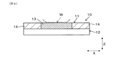
なお、本実施形態の説明のための図面において、ワークを置くための定盤の側面に沿った第1方向(水平方向)を矢印Xで示し、定盤の側面に垂直な第2方向を矢印Yで示し、第1方向及び第2方向の双方に垂直な第3方向(定盤の高さ方向)を矢印Zで示している。 In the drawings for describing the present embodiment, the first direction (horizontal direction) along the side surface of the platen for placing the work is indicated by an arrow X, and the second direction perpendicular to the side surface of the platen is an arrow A third direction (height direction of the platen) indicated by Y and perpendicular to both the first direction and the second direction is indicated by an arrow Z.
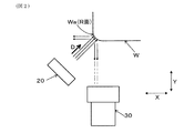
図1に示されるように、本実施形態の反り量測定装置1は、板状のワークWの板厚方向(第3方向Z)の反り量を測定する装置である。この反り量測定装置1は、定盤10と、照明装置20と、カメラ30と、処理装置40と、を備えている。
As FIG. 1 shows, the curvature amount measuring apparatus 1 of this embodiment is an apparatus which measures the curvature amount of the plate | board thickness direction (3rd direction Z) of the work W of plate shape. The warpage measuring device 1 includes a
ワークWの平面形状は、4つの角部を有する矩形である。このワークWの1つの角部WaにはR面加工が施されている。 The planar shape of the work W is a rectangle having four corners. An R-surface process is applied to one corner Wa of the work W.
定盤10は、ワークWを置くための上面11を有する水平な台として構成されている。上面11は第1方向X及び第2方向Yの双方によって規定される平面(基準面)である。ここでいう「反り量」は、定盤10の上面11に置かれたワークWについて、基準面である上面11に対するワーク端部の垂直方向(第3方向Z)の浮き量として定義される。定盤10の側面12は、第1方向X及び第3方向Zの双方によって規定される平面であり、照明装置20及びカメラ30に対向する対向面として構成されている。
The
照明装置20は、照明光を照射する機能を有する。本実施形態では、この照明装置20の光源としてLEDが使用されている。この照明装置20は、カメラ30の撮像面に対して斜め方向から、対象物であるワークW及び定盤10の双方に照明光を当てるように配置された斜光照明である。即ち、ワークWに照明光を当てる照明装置と、定盤10に照明光を当てる照明装置と、が1つの照明装置20によって兼務されている。これにより、照明装置の数を少なく抑えることができる。
The
なお、ワークWに照明光を当てる照明装置と、定盤10に照明光を当てる照明装置と、が別個に設けられてもよい。また、照明装置20の光源として、LED以外に、ハロゲンランプ、蛍光灯、タングステンランプ、メタルハライド、キセノンランプなどを使用することもできる。
Note that an illumination device for applying illumination light to the work W and an illumination device for applying illumination light to the
カメラ30は、定盤10の側方の所定の設定位置Pに配置された撮影部である。このカメラ30は、定盤10の上面11に置かれたワークWの角部Waを定盤10の側面12とともに所定の側方視点31から撮影する機能を有する。このカメラ30の撮影によって、視野32に含まれる対象物の画像がCCD素子(図示省略)によって検出される。カメラ30の視野32には、ワークWについては少なくとも角部Waが、定盤10については少なくとも側面12が含まれている。これにより、ワークWの角部Waと定盤10の側面12とのそれぞれの撮影画像を、カメラ30による1回の撮影で同時に得ることができる。
The
処理装置40は、カメラ30で撮影された撮影画像からワークWの反り量を演算する装置であり、画像処理部41、演算部42、出力部43及びメモリ44を備えている。この処理装置40として、カメラ30に常時に或いは一時的に接続されるパーソナルコンピュータ(PC)が使用されるのが好ましい。
The
画像処理部41は、カメラ30で撮影された撮影画像から、ワークWの4つの角部のうちの1つの角部Waを検出し、且つ定盤10の第2検出面14を検出する機能を有する。具体的には後述するが、演算部42は、画像処理部41で得られた情報に基づいて、ワークWの反り量を演算する機能を有する。出力部43は、演算部42による演算結果を出力する機能を有する。メモリ44は、画像処理部41で処理された処理情報、及び演算部42で演算された演算情報のそれぞれを記憶し、記憶した情報を必要に応じて読み出す機能を有する。
The
上記の定盤10の側面12は、第1検出面13と2つの第2検出面14,14とに区画されている。第1検出面13及び第2検出面14のいずれも、第3方向Zの高さが側面12と同じである。第1検出面13は、側面12のうち上面11に連接し且つワークWの角部Waの下方に位置する面として構成されている。第1検出面13は、水平方向である第1方向Xの長さがワークWの第1方向Xの長さを上回り、且つ第1方向Xの両端位置がワークWの両端位置よりも外側に配置されるように構成されている。本構成の場合、ワークWの角部Waの位置から定盤10の側面12に向けて垂直方向下向きに仮想線Hを引くと、この仮想線Hが必ず第1検出面13の領域内を通る。また、各第2検出面14は、側面12のうち上面11に連接し且つ水平方向(第1方向X)について第1検出面13に隣り合う面として構成されている。
The
そして、反り量測定装置1は、照明装置20の照射状態でワークW及び定盤10の双方を側方視点31からみたときの輝度について、角部WaがワークWの中で最も高く且つ第1検出面13よりも高くなり、第2検出面14が第1検出面13よりも高くなるように設定された構造(以下、「輝度設定構造」という。)を有する。
The warpage measuring device 1 is the first among the workpieces W with the highest corner portion Wa with respect to the luminance when both the workpiece W and the
ここでいう「輝度」は、照明装置20から照明が当てられた状態の対象物を側方視点31からみたときの相対的な明るさをいう。従って、側方視点31からみた対象物が周囲よりも明るい場合にこの対象物の輝度が高いといい、側方視点31からみた対象物が周囲よりも暗い場合にこの対象物の輝度が低いということができる。
Here, “brightness” refers to relative brightness when the object in a state where illumination is applied from the
上記の輝度設定構造を実現するために、本実施形態の反り量測定装置1は、以下の2つの特徴を有する。 In order to realize the above-described brightness setting structure, the warpage amount measuring apparatus 1 of the present embodiment has the following two features.
この反り量測定装置1の1つ目の特徴として、図2に示されるように、照明装置20は、ワークWの角部Waに向かう照射方向Dに照明光を照射するように構成されている。この照射方向Dは、ワークWに対しては、角部WaのR面の法線方向(R面に接する接平面に対して垂直な方向)に一致する。従って、本構成によれば、照明装置20の照射状態において、ワークWの角部Waは、ワークWの他の部位よりも輝度が高い状態でカメラ30によって撮影される。その結果、カメラ30によって得られた撮影画像において、ワークWの角部Waが最も明るい部分(白い部分)として強調されて認識されることになる。
As a first feature of the warpage measuring device 1, as shown in FIG. 2, the
この反り量測定装置1の2つ目の特徴として、定盤10の側面12の表面構造が第1検出面13と第2検出面14とで相異するように構成されている。具体的には、第1検出面13が反射素材によって構成される一方で、第2検出面14が拡散素材(「拡散反射素材」ともいう。)によって構成されている。
As a second feature of the warpage measuring device 1, the surface structure of the
第1検出面13の反射素材は、照明装置20の照明光に対して正反射率が高く且つ拡散反射率が低い素材である。この反射素材の全反射率の殆どを正反射率が占める。即ち、この反射素材において照明光の殆どが正反射する。本実施形態では、定盤10の側面12のうち第1検出面13に対応した領域に、表面が研磨された金属材料(反射素材)からなる板材が接合されている。
The reflective material of the
これに対して、第2検出面14の拡散素材は、照明装置20の照明光に対して拡散反射率が高く且つ正反射率が低い素材である。この拡散素材の全反射率の殆どを拡散反射率が占める。即ち、この拡散素材において照明光の殆どが拡散反射する。本実施形態では、定盤10の側面12のうち第2検出面14に対応した領域に、樹脂材料(拡散素材)からなる板材が接合されている。
On the other hand, the diffusion material of the
従って、定盤10は、照明装置20の照射状態で側面12を側方視点31からみたときの輝度について、第2検出面14が第1検出面13の素材よりも上記輝度が高い素材によって構成されている。
Therefore, the
図3に示されるように、照明装置20の照射方向Dは、定盤10の側面12に対しては、第2方向Yとの間に傾斜角度θをなす斜め方向である。この場合、第1検出面13で反射した反射光がカメラ30から外れた方向に進む一方で、第2検出面14で拡散した拡散光の一部がカメラ30に向けて進む。
As shown in FIG. 3, the irradiation direction D of the
このため、照明装置20の照射状態において、定盤10の側面12は、第2検出面14が第1検出面13よりも輝度が高い状態でカメラ30によって撮影される。その結果、カメラ30によって得られた撮影画像において、定盤10の側面12は、第1検出面13が相対的に暗い部分(黒い部分)として認識され、第2検出面14が相対的に明るい部分(白い部分)として強調されて認識されることになる。
Therefore, in the irradiation state of the
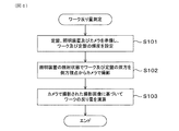
ここで、上記の反り量測定装置1を用いた反り量測定方法について具体定に説明する。この反り量測定方法は、板状のワークWの板厚方向(第3方向Z)の反り量を測定する方法であり、図4に示されるフローチャートのステップS101からS103までの処理を順次実行することによって達成される。なお、必要に応じてこのフローチャートに別のステップが追加されてもよいし、1つのステップが複数のステップに分割されてもよい。 Here, the method of measuring the amount of warpage using the above-described warpage amount measuring apparatus 1 will be specifically described. This method of measuring the amount of warpage is a method of measuring the amount of warpage in the thickness direction (third direction Z) of the plate-like work W, and sequentially executes the processes from step S101 to step S103 in the flowchart shown in FIG. Is achieved by Note that another step may be added to the flowchart as needed, or one step may be divided into a plurality of steps.
ステップS101は、前記の定盤10と、照明装置20と、カメラ30と、を準備し、前述のように照明装置20に対するワークW及び定盤10の輝度を設定する設定ステップである。このステップS101において、定盤10の側面12が第1検出面13と第2検出面14とに区画される。また、このステップS101において、照明装置20の照射状態でワークW及び定盤10の双方を側方視点31からみたときの輝度について角部WaがワークWの中で最も高く且つ第1検出面13よりも高くなり第2検出面14が第1検出面13よりも高くなるような輝度設定が行われる。
Step S101 is a setting step of preparing the
このステップS101において、作業者は、上記の輝度設定のために、第1検出面13が反射素材によって構成され第2検出面14が拡散素材によって構成された定盤10を準備する。また、作業者は、定盤10の上面11にワークWを置くとともに、定盤10の上面11に置かれたワークWの角部WaのR面の法線方向(照射方向D)に照明光が照射されるように照明装置20の向きを調整する。このとき、ワークWの角部Waが定盤10の上面11のうち側面12の第2検出面14に対応した領域内に入るように、ワークWの位置が調整される。なお、カメラ30による撮影時に定盤10とワークWのピントが合うようにするために、ワークWが定盤10の上面11に置かれた状態で、ワークWの側面が定盤10の側面12と面一になるように位置設定されるのが好ましい。
In this step S101, the worker prepares the
このステップS101によれば、ワークWの角部Waは、照明装置20の照射方向Dの設定によって、ワークWの他の部位や定盤10の第1検出面13よりも輝度が高くなるように設定される。また、第2検出面14は、素材の選定によって、第1検出面13よりも輝度が高くなるように設定される。このため、ワークW及び定盤10のそれぞれにおいて認識したい部位の輝度の設定を簡単に行うことができる。特に、ワークWの角部Waの輝度については、照明装置20の向きを調整するのみで輝度の設定を行うことができ、輝度の設定についてワークW自体に手を加える必要がない。
According to step S101, the corner portion Wa of the workpiece W has a luminance higher than that of other portions of the workpiece W and the
ステップS102は、ステップS101の実行後に実行される。このステップS102は、照明装置20の照射状態でカメラ30による撮影を行う撮影ステップである。このステップS102において、定盤10の上面11に置かれたワークWの角部Waが定盤10の側面12とともに側方視点31からカメラ30で撮影される。このステップS102は、作業者によって実行される。
Step S102 is performed after execution of step S101. This step S102 is a photographing step of photographing with the
このステップ102によれば、上述の輝度設定がなされたワークW及び定盤10をカメラ30によって撮影した撮影画像が得られる。
According to this step 102, a photographed image obtained by photographing the workpiece W and the
ステップS103は、ステップS102の実行後に実行される。このステップS103は、ステップS102においてカメラ30で撮影された撮影画像の明暗差に基づいてワークWの反り量を演算する処理ステップである。このステップS103は、処理装置40の画像処理部41及び演算部42によって実行される。
Step S103 is performed after execution of step S102. This step S103 is a processing step which calculates the amount of warpage of the work W based on the contrast of the image taken by the
このステップS103において、先ず、画像処理部41によって、カメラ30よって得られた撮影画像であるカラー画像を白黒2値化(「2階調化」ともいう。)する処理が実行される。この処理によれば、予め設定された閾値よりも明るいピクセルは全て白色に変換され、当該閾値よりも暗いピクセルは全て黒色に変換された白黒画像が得られる。これにより、ワークWは、角部Waのみが白色に変換され、その他の部位が黒色に変換される。一方で、定盤10の側面12は、第2検出面14のみが白色に変換され、第1検出面13が黒色に変換される。
In step S103, first, the
このとき、ステップS101における輝度設定の効果によって、白黒画像における白黒2値化について所望の結果が得られる。即ち、ワークWの角部Waが白い部分として強調され、且つ定盤10の側面12において第2検出面14が白い部分として強調された白黒画像が得られる。
なお、ここでいう白黒2値化は公知の処理であり、この処理についての更なる詳細な説明は省略する。
At this time, a desired result can be obtained for black and white binarization in a black and white image by the effect of the luminance setting in step S101. That is, a black and white image is obtained in which the corner portion Wa of the work W is emphasized as a white portion, and the
In addition, the black-and-white binarization here is a well-known process, and the further detailed description about this process is abbreviate | omitted.
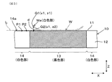
次いで、画像処理部41によって、撮影画像の明暗差に基づいてワークWの角部Wa及び定盤10の第2検出面14をそれぞれ検出する処理が実行される。この処理については図5が参照される。
Next, the
図5に示されるように、白黒画像においてワークWの角部Waは白色部であり、ワークWのその他の部位(黒色部)に対して強調されて表示される。このため、角部Waが位置する第1位置Q1(XZ座標(x1,z1))を正しく検出することができる。図5では、ワークWの角部Waの白色部(白点群)を「○」で示している。 As shown in FIG. 5, in the black and white image, the corner Wa of the workpiece W is a white portion, and is displayed with emphasis on the other portion (black portion) of the workpiece W. Therefore, it is possible to correctly detect the first position Q1 (XZ coordinate (x1, z1)) where the corner portion Wa is located. In FIG. 5, the white part (white point group) of the corner Wa of the work W is indicated by “o”.
このとき、白色部(白点群)の第3方向Zの最下点を第1位置Q1とし、ワークWの角部Waのうちワーク下面との境界点をこの第1位置Q1として検出するのが好ましい。これに対して、白色部(白点群)の第3方向Zの最上点を第1位置Q1としてもよい。この場合は、ワークWの角部Waのうちワーク上面との境界点がこの第1位置Q1として検出される。 At this time, the lowest point of the white portion (white point group) in the third direction Z is set as the first position Q1, and the boundary point of the corner portion Wa of the workpiece W with the lower surface of the workpiece is detected as the first position Q1. Is preferred. On the other hand, the uppermost point of the white portion (white point group) in the third direction Z may be set as the first position Q1. In this case, a boundary point with the upper surface of the work in the corner Wa of the work W is detected as the first position Q1.
また、白黒画像において第2検出面14は白色部であり、黒色部である第1検出面13に対して強調されて表示される。ここで、図5中の基準線L上にある、第1位置Q1の直下の位置を第2位置Q2(XZ座標(x1,z2))として正しく検出することができる。第2位置Q2は、第1検出面13と上面11との境界にあり、第1位置Q1を通る第3方向Zの直線と基準線Lとの交点として定められる。この場合、第2検出面14のうち上面11に連接する上辺14aの少なくとも2点P1,P2から、この上辺14aを通る水平方向(第1方向X)の直線を求め、この直線を基準線Lとすることができる。或いは、(図5中左側の)一方の第2検出面14の上辺14a上の点と、(図5中右側の)他方の第2検出面14の上辺14a上の点とを結ぶ直線を基準線Lとしてもよい。
Further, in the black and white image, the
その後、演算部42は、第2位置Q2から第1位置Q1までの垂直方向の距離を用いて、ワークWの反り量d(即ち、ワークWの角部Waの第3方向Zの浮き量)を演算する。このとき、ワークWの角部Waのうちワーク下面との境界点を第1位置Q1として検出している場合には、上記の垂直方向の距離がワークWの板厚方向(第3方向Z)の反り量となる。これに対して、ワークWの角部Waのうちワーク上面との境界点を第1位置Q1として検出している場合には、上記の垂直方向の距離からワークWの板厚を差し引いた値がワークWの板厚方向(第3方向Z)の反り量となる。この演算部42による演算結果は、出力部43によって画面に表示出力され、必要に応じてメモリ44に記憶される。
After that, the
従って、処理装置40を用いたステップS103の処理によれば、カメラ30で撮影された撮影画像からワークWの反り量を自動で簡単に演算することができる。
Therefore, according to the process of step S103 using the
なお、ワークWの反り量を測定する上述の処理は、ワークWの品質管理のためには、1つの角部Waについてのみならず4つの角部の全てについて実施されるのが好ましい。 In addition, it is preferable that the above-mentioned process which measures the curvature amount of the workpiece | work W is implemented not only about one corner | angular part Wa but about all four corner | angular parts for quality control of the workpiece | work W.
上述の反り量測定装置1及び反り量測定方法によれば、以下のような作用効果が得られる。 According to the above-described warpage amount measuring apparatus 1 and the warpage amount measuring method, the following effects can be obtained.
定盤10の上面11に置かれた板状のワークWは、照明装置20によって照明光が当てられた状態でカメラ30によって側方視点31から撮影される。このとき、ワークWの角部Waは、ワークWの他の部位や定盤10の第1検出面13に対して相対的に輝度が高い状態で検出される。このため、カメラ30によって撮影された撮影画像において、ワークWの反り量を求めるのに用いる角部Waの位置(図5中の第1位置Q1)を、ワークWの他の部位及び第1検出面13との輝度の違い(明暗差)によって正しく検出できる。
The plate-like work W placed on the
一方で、ワークWの角部Waの検出のために定盤10の第1検出面13の輝度を相対的に低くすると、ワークWの実際の反り量が微小或いはゼロのとき(例えば、図6に示される状態の場合)に、ワークWの角部Waの位置が誤認識されるおそれがある。
On the other hand, when the luminance of the
そこで、本実施形態において、定盤10の第2検出面14は、その輝度が第1検出面13の輝度よりも高い状態でカメラ30によって撮影されるように設定されている。このため、カメラ30によって撮影された撮影画像において、第2検出面14を第1検出面13との輝度の違い(明暗差)によって容易に検出できる。
Therefore, in the present embodiment, the
このとき、第2検出面14の上辺14aの位置が定盤10の上面11の位置に一致するため、この上辺14aの位置を正しく検出することによって、ワークWの反り量を求めるのに用いる定盤10の上面11の位置も正しく検出できる。そして、いずれも正しく検出されたワークWの角部Waの位置と定盤10の上面11の位置との双方の位置情報を用いることによって、ワークWの反り量が精度良く求められる。
At this time, since the position of the
その結果、板状のワークWの反り量を精度良く測定することが可能になる。特に、ワークWの実際の反り量が微小或いはゼロのときでもワークWの角部Waの位置を正しく検出できる。また、ワークWの反り量の測定のために、レーザ測定器のような高価な機器を使用する必要がなく、安価な測定システムを構築できる。 As a result, it is possible to measure the amount of warpage of the plate-like work W with high accuracy. In particular, even when the actual amount of warpage of the workpiece W is small or zero, the position of the corner Wa of the workpiece W can be detected correctly. In addition, it is not necessary to use an expensive device such as a laser measuring instrument to measure the amount of warpage of the workpiece W, and an inexpensive measuring system can be constructed.
また、図7が参照されるように、ワーク上面Wbに別の要素Aが積層された構造において、下側に位置するワークWの反り量を測定したい場合、別の要素Aが邪魔になってワーク上面Wbの三次元形状からワークWの反り量を測定するのは難しい。これに対して、本実施形態は、ワークWの角部Waの位置を直接的に検出する方法を採用しており、別の要素Aが邪魔になることなくワークWの反り量を精度良く検出するのに効果がある。 Further, as shown in FIG. 7, in the structure in which another element A is stacked on the upper surface Wb of the work, when it is desired to measure the amount of warpage of the work W located on the lower side, the other element A is in the way It is difficult to measure the amount of warpage of the workpiece W from the three-dimensional shape of the workpiece top surface Wb. On the other hand, this embodiment adopts a method of directly detecting the position of the corner Wa of the workpiece W, and accurately detects the amount of warpage of the workpiece W without the other element A being in the way It is effective to
定盤10の側面12を第1検出面13と第2検出面14とに区画する形態として、図1に示される形態以外に、例えば図8〜図10に示される各変更例を採用することもできる。
As an embodiment in which the
(第1変更例)
図8に示される第1変更例において、定盤10は、第1検出面13及び2つの第2検出面14,14がいずれも、上面11に連接し且つ第3方向Zの高さが側面12を下回るように構成されている。
(First Modification)
In the first modification shown in FIG. 8, the
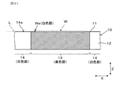
(第2変更例)
図9に示される第2変更例において、定盤10は、第1検出面13及び第2検出面14のそれぞれの数が1つであり、第1検出面13及び第2検出面14のいずれも、上面11に連接し且つ第3方向Zの高さが側面12と一致するように構成されている。
(Second change example)
In the second modification shown in FIG. 9, the number of each of the
(第3変更例)
図10に示される第3変更例において、定盤10は、第1検出面13及び第2検出面14のいずれも、上面11に連接し且つ第3方向Zの高さが側面12を下回るように構成されている。
(Third Modification)
In the third modification shown in FIG. 10, both the
即ち、ワークWの角部Waの下方に第1検出面13が配置され、且つ第1検出面13及び第2検出面14がいずれも定盤10の上面11に連接した構成であれば、各検出面の大きさや数は定義に変更可能である。
That is, if the
本発明は、上記の本実施形態のみに限定されるものではなく、本発明の目的を逸脱しない限りにおいて種々の応用や変形が考えられる。例えば、本実施形態を応用した次の各形
態を実施することもできる。
The present invention is not limited to the above-described embodiment, and various applications and modifications can be considered without departing from the object of the present invention. For example, the following embodiments to which this embodiment is applied can be implemented.
上記の実施形態では、照明装置20の向きを調整することによってワークWの角部Waの輝度の設定を行う場合について例示したが、これに代えて、ワークWの角部Waに輝度を高めるための部材を接着してもよい。
Although the above embodiment exemplifies the setting of the luminance of the corner Wa of the workpiece W by adjusting the direction of the
上記の実施形態では、定盤10の側面12の第1検出面13及び第2検出面14のそれぞれを構成する素材を選択することによって2つの検出面13,14における輝度の設定を行う場合について例示したが、別の構造によって当該輝度の設定を行うようにしてもよい。別の構造として、例えば第1検出面13が黒色に塗色され且つ第2検出面14が白色に塗色された構成や、照明装置20の向きや設置数などが変更された構成などが挙げられる。
In the above embodiment, in the case of setting the luminance in the two
上記の実施形態では、第1検出面13を構成する反射素材として金属材料を使用する場合について例示したが、所望の正反射率を得ることができればこの反射素材として金属材料以外の材料を使用してもよい。同様に、第2検出面14を構成する拡散素材として樹脂材料を使用する場合について例示したが、所望の拡散反射率を得ることができればこの拡散素材として樹脂材料以外の材料を使用してもよい。
Although the above embodiment exemplifies the case where a metal material is used as the reflective material constituting the
上記の実施形態では、反り量測定装置1が処理装置40を備える場合について例示したが、必要に応じて処理装置40を省略し、処理装置40が実行する処理、即ちカメラ30による撮影画像からワークWの反り量を求める処理を作業者が行うようにしてもよい。
Although the above embodiment exemplifies the case where the warpage measuring device 1 includes the
上記の実施形態では、測定対象であるワークWが4つの角部を有する場合について例示したが、少なくとも1つの角部を有する板状のワークを測定対象とすることができる。 Although the above embodiment exemplifies the case where the workpiece W to be measured has four corner portions, a plate-like workpiece having at least one corner portion can be a measurement target.
1 反り量測定装置
10 定盤
11 上面
12 側面
13 第1検出面
14 第2検出面
14a 上辺
20 照明装置
30 カメラ
31 側方視点
40 処理装置
d 反り量
Q1 第1位置
Q2 第2位置
W ワーク
Wa 角部
S101 設定ステップ
S102 撮影ステップ
S103 処理ステップ
DESCRIPTION OF SYMBOLS 1
Claims (6)
定盤と、照明光を照射する照明装置と、上記定盤の上面に置かれた上記ワークの角部を上記定盤の側面とともに側方視点から撮影するカメラと、を備え、
上記定盤の上記側面が、上記上面に連接し且つ上記ワークの上記角部の下方に位置する第1検出面と、上記上面に連接し且つ水平方向について上記第1検出面に隣り合う第2検出面と、に区画されるとともに、上記照明装置の照射状態で上記ワーク及び上記定盤の双方を上記側方視点からみたときの輝度について上記角部が上記ワークの中で最も高く且つ上記第1検出面よりも高くなり上記第2検出面が上記第1検出面よりも高くなるように構成されている、ワークの反り量測定装置。 A workpiece warpage measuring device that measures the amount of warping of a plate-like workpiece, and
A surface plate, an illumination device for emitting illumination light, and a camera for photographing a corner portion of the work placed on the upper surface of the surface plate together with the side surface of the surface plate from a side view point,
The side surface of the surface plate is connected to the upper surface, and a first detection surface located below the corner of the workpiece, and a second detection surface connected to the upper surface and adjacent to the first detection surface in the horizontal direction The corner is the highest among the workpieces and the luminance of the workpiece and the surface plate are both viewed from the side point of view in the irradiation state of the illumination device while being divided into the detection surface. A device for measuring the amount of warpage of a work, wherein the second detection surface is higher than the first detection surface and higher than the first detection surface.
定盤と、照明光を照射する照明装置と、上記定盤の上面に置かれた上記ワークの角部を上記定盤の側面とともに側方視点から撮影するカメラと、を準備し、上記定盤の上記側面を、上記上面に連接し且つ上記ワークの上記角部の下方に位置する第1検出面と、上記上面に連接し且つ水平方向について上記第1検出面に隣り合う第2検出面と、に区画するとともに、上記照明装置の照射状態で上記ワーク及び上記定盤の双方を上記側方視点からみたときの輝度について上記角部が上記ワークの中で最も高く且つ上記第1検出面よりも高くなり上記第2検出面が上記第1検出面よりも高くなるように設定する設定ステップと、
上記照明装置の上記照射状態で上記カメラによる撮影を行う撮影ステップと、
を有する、ワークの反り量測定方法。 It is a method of measuring the amount of warpage of a work which measures the amount of warpage of a plate-like work,
Prepare a platen, an illumination device for emitting illumination light, and a camera for photographing the corner of the work placed on the upper surface of the platen together with the side surface of the platen from a side view point; A first detection surface connected to the upper surface and located below the corner of the work; and a second detection surface connected to the upper surface and adjacent to the first detection surface in the horizontal direction In the irradiation state of the illumination device, the corner is the highest in the work and the first detection surface with respect to the brightness when both the work and the surface plate are viewed from the side point of view in the irradiation state of the illumination device Setting the second detection surface to be higher than the first detection surface,
A photographing step of photographing with the camera in the irradiation state of the illumination device;
A method of measuring the amount of warpage of a workpiece.
Priority Applications (1)
| Application Number | Priority Date | Filing Date | Title |
|---|---|---|---|
| JP2016108669A JP6524968B2 (en) | 2016-05-31 | 2016-05-31 | Workpiece warpage measuring method and warpage measuring apparatus |
Applications Claiming Priority (1)
| Application Number | Priority Date | Filing Date | Title |
|---|---|---|---|
| JP2016108669A JP6524968B2 (en) | 2016-05-31 | 2016-05-31 | Workpiece warpage measuring method and warpage measuring apparatus |
Publications (2)
| Publication Number | Publication Date |
|---|---|
| JP2017215187A JP2017215187A (en) | 2017-12-07 |
| JP6524968B2 true JP6524968B2 (en) | 2019-06-05 |
Family
ID=60576766
Family Applications (1)
| Application Number | Title | Priority Date | Filing Date |
|---|---|---|---|
| JP2016108669A Active JP6524968B2 (en) | 2016-05-31 | 2016-05-31 | Workpiece warpage measuring method and warpage measuring apparatus |
Country Status (1)
| Country | Link |
|---|---|
| JP (1) | JP6524968B2 (en) |
Family Cites Families (6)
| Publication number | Priority date | Publication date | Assignee | Title |
|---|---|---|---|---|
| JPH02194307A (en) * | 1989-01-23 | 1990-07-31 | Kawasaki Steel Corp | Curvature shape measuring instrument for plate-like body |
| JPH08285550A (en) * | 1995-04-10 | 1996-11-01 | Tokai Carbon Co Ltd | Steel plate displacement measuring device |
| JP3823794B2 (en) * | 2000-10-03 | 2006-09-20 | Jfeスチール株式会社 | Thin plate shape control device and thin plate shape control method |
| JP3724720B2 (en) * | 2001-12-20 | 2005-12-07 | 住友金属工業株式会社 | Warpage shape measuring method and apparatus |
| JP5233372B2 (en) * | 2008-04-03 | 2013-07-10 | 新日鐵住金株式会社 | Steel plate warpage detection system and method |
| CN101750018A (en) * | 2008-11-28 | 2010-06-23 | 北京航空航天大学 | Non-contact real-time displacement measuring method and device in bending deformation process of work piece |
-
2016
- 2016-05-31 JP JP2016108669A patent/JP6524968B2/en active Active
Also Published As
| Publication number | Publication date |
|---|---|
| JP2017215187A (en) | 2017-12-07 |
Similar Documents
| Publication | Publication Date | Title |
|---|---|---|
| CN103328959B (en) | Board inspection device, board inspection system, and board inspection result confirmation screen display method | |
| CN101013028A (en) | Image processing method and image processor | |
| JP6507653B2 (en) | Inspection apparatus and control method of inspection apparatus | |
| JP6519265B2 (en) | Image processing method | |
| CN107429991B (en) | Appearance inspection device and appearance inspection method | |
| CN102483380B (en) | Illumination/image-pickup system for surface inspection and data structure | |
| JP5438475B2 (en) | Gap step measurement device, gap step measurement method, and program thereof | |
| JP2013205071A (en) | Visual inspection device and visual inspection method | |
| WO2019082584A1 (en) | Information processing device | |
| JP7135418B2 (en) | FLATNESS DETECTION METHOD, FLATNESS DETECTION APPARATUS AND FLATNESS DETECTION PROGRAM | |
| JP2009036736A (en) | Printed soft solder inspection method and device | |
| JP2006023178A (en) | 3-dimensional measuring method and device | |
| EP3326366B1 (en) | Measuring rotational position of lenticular lens sheet | |
| JP6524968B2 (en) | Workpiece warpage measuring method and warpage measuring apparatus | |
| CN114689604B (en) | Image processing method and detection system for optical detection of an object to be detected with a smooth surface | |
| JP2020134491A (en) | Inspection unit, program and storage medium | |
| CN111566438B (en) | Image acquisition method and system | |
| JP6781969B1 (en) | Measuring device and measuring method | |
| JP2011220755A (en) | Surface appearance inspection apparatus | |
| JP6648684B2 (en) | Workpiece warpage measuring device and warpage measuring method | |
| JP2020129187A (en) | Outline recognition device, outline recognition system, and outline recognition method | |
| JP7459525B2 (en) | Three-dimensional shape measuring device, three-dimensional shape measuring method and program | |
| US20250139759A1 (en) | Image processing apparatus, image processing method, and non-transitory computer-readable storage medium | |
| JP6225719B2 (en) | Straightness measuring device, straightness measuring method, and program | |
| TWI675350B (en) | Image Processing Apparatus And Method |
Legal Events
| Date | Code | Title | Description |
|---|---|---|---|
| A621 | Written request for application examination |
Free format text: JAPANESE INTERMEDIATE CODE: A621 Effective date: 20180719 |
|
| TRDD | Decision of grant or rejection written | ||
| A01 | Written decision to grant a patent or to grant a registration (utility model) |
Free format text: JAPANESE INTERMEDIATE CODE: A01 Effective date: 20190409 |
|
| A977 | Report on retrieval |
Free format text: JAPANESE INTERMEDIATE CODE: A971007 Effective date: 20190410 |
|
| A61 | First payment of annual fees (during grant procedure) |
Free format text: JAPANESE INTERMEDIATE CODE: A61 Effective date: 20190422 |
|
| R150 | Certificate of patent or registration of utility model |
Ref document number: 6524968 Country of ref document: JP Free format text: JAPANESE INTERMEDIATE CODE: R150 |
|
| R250 | Receipt of annual fees |
Free format text: JAPANESE INTERMEDIATE CODE: R250 |
|
| R250 | Receipt of annual fees |
Free format text: JAPANESE INTERMEDIATE CODE: R250 |
|
| R250 | Receipt of annual fees |
Free format text: JAPANESE INTERMEDIATE CODE: R250 |
|
| R250 | Receipt of annual fees |
Free format text: JAPANESE INTERMEDIATE CODE: R250 |