JP6521637B2 - Measurement apparatus, lithographic apparatus, and method of manufacturing article - Google Patents
Measurement apparatus, lithographic apparatus, and method of manufacturing article Download PDFInfo
- Publication number
- JP6521637B2 JP6521637B2 JP2015003608A JP2015003608A JP6521637B2 JP 6521637 B2 JP6521637 B2 JP 6521637B2 JP 2015003608 A JP2015003608 A JP 2015003608A JP 2015003608 A JP2015003608 A JP 2015003608A JP 6521637 B2 JP6521637 B2 JP 6521637B2
- Authority
- JP
- Japan
- Prior art keywords
- mark
- measurement
- reticle
- processing unit
- measuring device
- Prior art date
- Legal status (The legal status is an assumption and is not a legal conclusion. Google has not performed a legal analysis and makes no representation as to the accuracy of the status listed.)
- Active
Links
Images


Classifications
-
- G—PHYSICS
- G03—PHOTOGRAPHY; CINEMATOGRAPHY; ANALOGOUS TECHNIQUES USING WAVES OTHER THAN OPTICAL WAVES; ELECTROGRAPHY; HOLOGRAPHY
- G03F—PHOTOMECHANICAL PRODUCTION OF TEXTURED OR PATTERNED SURFACES, e.g. FOR PRINTING, FOR PROCESSING OF SEMICONDUCTOR DEVICES; MATERIALS THEREFOR; ORIGINALS THEREFOR; APPARATUS SPECIALLY ADAPTED THEREFOR
- G03F9/00—Registration or positioning of originals, masks, frames, photographic sheets or textured or patterned surfaces, e.g. automatically
- G03F9/70—Registration or positioning of originals, masks, frames, photographic sheets or textured or patterned surfaces, e.g. automatically for microlithography
- G03F9/7088—Alignment mark detection, e.g. TTR, TTL, off-axis detection, array detector, video detection
-
- G—PHYSICS
- G03—PHOTOGRAPHY; CINEMATOGRAPHY; ANALOGOUS TECHNIQUES USING WAVES OTHER THAN OPTICAL WAVES; ELECTROGRAPHY; HOLOGRAPHY
- G03F—PHOTOMECHANICAL PRODUCTION OF TEXTURED OR PATTERNED SURFACES, e.g. FOR PRINTING, FOR PROCESSING OF SEMICONDUCTOR DEVICES; MATERIALS THEREFOR; ORIGINALS THEREFOR; APPARATUS SPECIALLY ADAPTED THEREFOR
- G03F9/00—Registration or positioning of originals, masks, frames, photographic sheets or textured or patterned surfaces, e.g. automatically
- G03F9/70—Registration or positioning of originals, masks, frames, photographic sheets or textured or patterned surfaces, e.g. automatically for microlithography
- G03F9/7003—Alignment type or strategy, e.g. leveling, global alignment
- G03F9/7007—Alignment other than original with workpiece
- G03F9/7011—Pre-exposure scan; original with original holder alignment; Prealignment, i.e. workpiece with workpiece holder
-
- G—PHYSICS
- G01—MEASURING; TESTING
- G01B—MEASURING LENGTH, THICKNESS OR SIMILAR LINEAR DIMENSIONS; MEASURING ANGLES; MEASURING AREAS; MEASURING IRREGULARITIES OF SURFACES OR CONTOURS
- G01B11/00—Measuring arrangements characterised by the use of optical techniques
- G01B11/26—Measuring arrangements characterised by the use of optical techniques for measuring angles or tapers; for testing the alignment of axes
- G01B11/27—Measuring arrangements characterised by the use of optical techniques for measuring angles or tapers; for testing the alignment of axes for testing the alignment of axes
- G01B11/272—Measuring arrangements characterised by the use of optical techniques for measuring angles or tapers; for testing the alignment of axes for testing the alignment of axes using photoelectric detection means
-
- G—PHYSICS
- G03—PHOTOGRAPHY; CINEMATOGRAPHY; ANALOGOUS TECHNIQUES USING WAVES OTHER THAN OPTICAL WAVES; ELECTROGRAPHY; HOLOGRAPHY
- G03F—PHOTOMECHANICAL PRODUCTION OF TEXTURED OR PATTERNED SURFACES, e.g. FOR PRINTING, FOR PROCESSING OF SEMICONDUCTOR DEVICES; MATERIALS THEREFOR; ORIGINALS THEREFOR; APPARATUS SPECIALLY ADAPTED THEREFOR
- G03F7/00—Photomechanical, e.g. photolithographic, production of textured or patterned surfaces, e.g. printing surfaces; Materials therefor, e.g. comprising photoresists; Apparatus specially adapted therefor
- G03F7/70—Microphotolithographic exposure; Apparatus therefor
- G03F7/70691—Handling of masks or workpieces
- G03F7/70775—Position control, e.g. interferometers or encoders for determining the stage position
-
- G—PHYSICS
- G03—PHOTOGRAPHY; CINEMATOGRAPHY; ANALOGOUS TECHNIQUES USING WAVES OTHER THAN OPTICAL WAVES; ELECTROGRAPHY; HOLOGRAPHY
- G03F—PHOTOMECHANICAL PRODUCTION OF TEXTURED OR PATTERNED SURFACES, e.g. FOR PRINTING, FOR PROCESSING OF SEMICONDUCTOR DEVICES; MATERIALS THEREFOR; ORIGINALS THEREFOR; APPARATUS SPECIALLY ADAPTED THEREFOR
- G03F9/00—Registration or positioning of originals, masks, frames, photographic sheets or textured or patterned surfaces, e.g. automatically
- G03F9/70—Registration or positioning of originals, masks, frames, photographic sheets or textured or patterned surfaces, e.g. automatically for microlithography
- G03F9/7003—Alignment type or strategy, e.g. leveling, global alignment
- G03F9/7046—Strategy, e.g. mark, sensor or wavelength selection
-
- G—PHYSICS
- G03—PHOTOGRAPHY; CINEMATOGRAPHY; ANALOGOUS TECHNIQUES USING WAVES OTHER THAN OPTICAL WAVES; ELECTROGRAPHY; HOLOGRAPHY
- G03F—PHOTOMECHANICAL PRODUCTION OF TEXTURED OR PATTERNED SURFACES, e.g. FOR PRINTING, FOR PROCESSING OF SEMICONDUCTOR DEVICES; MATERIALS THEREFOR; ORIGINALS THEREFOR; APPARATUS SPECIALLY ADAPTED THEREFOR
- G03F9/00—Registration or positioning of originals, masks, frames, photographic sheets or textured or patterned surfaces, e.g. automatically
- G03F9/70—Registration or positioning of originals, masks, frames, photographic sheets or textured or patterned surfaces, e.g. automatically for microlithography
- G03F9/7092—Signal processing
Description
本発明は、計測装置、リソグラフィ装置及び物品の製造方法に関する。 The present invention relates to a measurement apparatus, a lithographic apparatus and a method of manufacturing an article.
半導体デバイスの微細化や高集積化に伴い、かかる半導体デバイスの製造に用いられるリソグラフィ装置(例えば、露光装置)には、高性能化が要求されている。例えば、レチクル(マスク)と基板との位置合わせ精度は、露光装置の性能として重要であり、レチクルのパターンの像と基板に形成されているパターンとをナノメートルのオーダーで位置合わせする技術が求められている。 Along with the miniaturization and high integration of semiconductor devices, higher performance is required of a lithographic apparatus (for example, an exposure apparatus) used to manufacture such semiconductor devices. For example, the alignment accuracy between the reticle (mask) and the substrate is important as the performance of the exposure apparatus, and a technique for aligning the image of the reticle pattern and the pattern formed on the substrate on the order of nanometers is required. It is done.
露光装置は、基板のステップ移動を介在させて、レチクルのパターンを基板のショット領域に順次転写する。このような露光装置には、かかる転写を一括で行う所謂ステッパーと、かかる転写を基板を走査しながら行う所謂スキャナーとがある。 The exposure apparatus sequentially transfers the pattern of the reticle onto the shot area of the substrate via the step movement of the substrate. Such an exposure apparatus includes a so-called stepper which performs such transfer collectively, and a so-called scanner which performs such transfer while scanning a substrate.
レチクルステージに対するレチクルの位置合わせ(レチクルアライメントとも呼ばれる)は、レチクルの下面に設けられたレチクルマークと、レチクルステージの上面に設けられた基準マークとを検出して行われうる(特許文献1参照)。これにより、例えば、レチクルステージに対するレチクルの位置ずれ量が計測されうる。従って、レチクルのパターンを基板に転写するのに、レチクルステージの位置及び基板ステージの位置のうち少なくとも一方を補正してレチクルのパターン像と基板との位置合わせを高精度に行いうる。 Alignment of the reticle to the reticle stage (also referred to as reticle alignment) can be performed by detecting a reticle mark provided on the lower surface of the reticle and a reference mark provided on the upper surface of the reticle stage (see Patent Document 1). . Thereby, for example, the positional deviation amount of the reticle with respect to the reticle stage can be measured. Therefore, in order to transfer the pattern of the reticle onto the substrate, at least one of the position of the reticle stage and the position of the substrate stage can be corrected to align the pattern image of the reticle with the substrate with high accuracy.
レチクルマークや基準マークにパーティクル(塵)が付着していたり、傷などの欠陥があったりする場合、かかるマークの位置を誤計測する可能性がある。そのため、そのような場合、レチクルアライメント処理をエラーとして停止させている。しかしながら、様々なオーバーレイ要求精度を有する基板を処理するところ、パーティクルや傷による計測誤差が精度上無視できる場合であっても処理を停止させると、露光装置(計測装置)のスループットを損ねてしまう。 If particles (dust) are attached to the reticle mark or the reference mark, or if there is a defect such as a scratch, the position of the mark may be erroneously measured. Therefore, in such a case, reticle alignment processing is stopped as an error. However, when processing a substrate having various overlay accuracy requirements, if the process is stopped even if measurement errors due to particles or scratches can be ignored for accuracy, the throughput of the exposure apparatus (measurement apparatus) is impaired.
本発明は、スループットの点で有利な計測装置を提供することを例示的目的とする。 The present invention has an exemplary object to provide a measurement device that is advantageous in terms of throughput.
上記目的を達成するために、本発明の一側面としての計測装置は、対象物の位置を計測する計測装置であって、前記対象物に形成されたマークの画像を取得する検出部と、前記取得した画像から検出データを生成し、前記検出データに基づいて前記対象物の位置を得る処理部と、を有し、前記処理部は、前記マークの領域が分割された前記画像の部分から複数の検出データを生成し、前記複数の検出データのそれぞれに対する位置計測誤差を評価し、前記複数の検出データから、前記評価した位置計測誤差に基づいて、前記計測装置による前記対象物の位置の計測に要求される精度の許容範囲に収まる部分を選択し、前記複数の検出データのうちの前記選択した部分に基づいて前記対象物の位置を得ることを特徴とする。 To achieve the above object, the measuring apparatus according to one aspect of the present invention, there is provided a measuring device for measuring the position of the object, a detection unit for acquiring an image of a mark formed on the object, wherein And a processing unit that generates detection data from the acquired image and obtains the position of the object based on the detection data , and the processing unit generates a plurality of portions from the image portion into which the area of the mark is divided. Detection data of each of the plurality of detection data is evaluated, and the position of the object is measured by the measuring device based on the evaluated position measurement error from the plurality of detection data Selecting a portion that falls within the tolerance of the accuracy required for the position of the object based on the selected portion of the plurality of detection data .
本発明の更なる目的又はその他の側面は、以下、添付図面を参照して説明される好ましい実施形態によって明らかにされるであろう。 Further objects or other aspects of the present invention will be made clear by the preferred embodiments described below with reference to the accompanying drawings.
本発明によれば、例えば、スループットの点で有利な計測装置を提供することができる。 According to the present invention, for example, it is possible to provide a measurement apparatus that is advantageous in terms of throughput.
以下、添付図面を参照して、本発明の好適な実施の形態について説明する。なお、各図において、同一の部材については同一の参照番号を付し、重複する説明は省略する。 Hereinafter, preferred embodiments of the present invention will be described with reference to the accompanying drawings. In each of the drawings, the same members are denoted by the same reference numerals, and redundant description will be omitted.
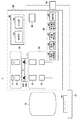
図1は、本発明の一側面としての露光装置1の構成を示す概略図である。露光装置1は、パターン形成をビームで基板に行うリソグラフィ装置である。露光装置1は、レチクル(マスク)を介して基板を露光する。露光装置1は、レチクルRを照明する照明光学系(不図示)と、レチクルRを保持して可動のレチクルステージ(保持部)11と、計測装置20と、レチクルRのパターンを基板Wに投影する投影光学系12とを有する。また、露光装置1は、基板Wを保持して可動の基板ステージ(保持部)13と、CPUやメモリなどを含み、露光装置1の全体(動作)を制御する制御部14とを有する。
FIG. 1 is a schematic view showing the arrangement of an
レチクルRは、パターン形成のための原版であって、レチクル搬送系(不図示)によってレチクルステージ11に搬入される。レチクルRの下面には、レチクルマークRMが設けられている。また、レチクルステージ11の上面には、基準マークSMが設けられている。
The reticle R is an original for forming a pattern, and is carried onto the
レチクルマークRM及び基準マークSMのそれぞれは、図2に示すように、X軸方向の位置を計測するためのXマークと、Y軸方向の位置を計測するためのYマークとを含む。また、レチクルマークRM及び基準マークSMにおいて、Xマーク及びYマークのそれぞれは、複数のバーマーク(マーク要素)で構成されている。 Each of reticle mark RM and reference mark SM includes an X mark for measuring the position in the X-axis direction and a Y mark for measuring the position in the Y-axis direction, as shown in FIG. In reticle mark RM and reference mark SM, each of the X mark and the Y mark is composed of a plurality of bar marks (mark elements).
本実施形態では、レチクルマークRMは、図3(a)に示すように、複数のYバーマークRMBY1乃至RMBY8で構成されたYマークと、複数のXバーマークRMBX1乃至RMBX10で構成されたXマークとを含む。基準マークSMは、図3(b)に示すように、複数のYバーマークSMBYL1乃至SMBYL8と、複数のYバーマークSMBYR1乃至SMBYR8とで構成されたYマークを含む。また、基準マークSMは、複数のXバーマークSMBXL1乃至SMBXL6と、複数のXバーマークSMBXR1乃至SMBXR6とで構成されたXマークを含む。このように、レチクルマークRM及び基準マークSMにおいて、Xマーク及びYマークのそれぞれを複数のバーマークで構成することで、平均化効果によって計測精度を向上させることができる。 In the present embodiment, as shown in FIG. 3A, the reticle mark RM is a Y mark formed of a plurality of Y bar marks RMBY1 to RMBY8 and an X mark formed of a plurality of X bar marks RMBX1 to RMBX10. And. As shown in FIG. 3B, the reference mark SM includes a Y mark composed of a plurality of Y bar marks SMBYL1 to SMBYL8 and a plurality of Y bar marks SMBYR1 to SMBYR8. In addition, the reference mark SM includes an X mark composed of a plurality of X bar marks SMBXL1 to SMBXL6 and a plurality of X bar marks SMBXR1 to SMBXR6. As described above, by forming each of the X mark and the Y mark with the plurality of bar marks in the reticle mark RM and the reference mark SM, the measurement accuracy can be improved by the averaging effect.
レチクルRは、レチクルマークRMと基準マークSMとが重ね合わさるように、レチクルステージ11に保持される。計測装置20は、レチクルマークRMと基準マークSMとの相対的な位置(位置関係)、即ち、レチクルステージ11におけるレチクルRの位置を計測する。計測装置20は、アライメントスコープ30と、画像処理部40と、オーバーレイ要求精度部50と、通知部60とを含む。オーバーレイ要求精度部50は、設定部51と、記憶部52とを含み、レチクルRと基板Wとの位置合わせに要求される精度、即ち、計測装置20による対象物の位置の計測に要求される精度(オーバーレイ要求精度)を設定及び記憶する。
Reticle R is held by
アライメントスコープ30は、光源31と、照明系32と、対物系33と、撮像素子34とを含む。アライメントスコープ30は、レチクルマークRMと基準マークSMとを撮像して、図2に示すような画像IMGを取得する。画像IMGは、2次元画像である。
The
画像処理部40は、画像記憶部41と、領域分割部42と、位置特定部43と、誤差量推定部44と、選択部45とを含む。画像処理部40は、アライメントスコープ30で撮像された画像IMGを処理して、レチクルステージ11におけるレチクルRの位置を求める。アライメントスコープ30で撮像された画像IMGは、画像記憶部41に記憶される。画像処理部40は、図3(a)に示すように、レチクルマークRMのYマークに対して設定された計測窓WIN−Yにおける光量を一方向に積算することで、図4に示すような1次元の積算波形(検出信号)を生成する。このように、アライメントスコープ30及び画像処理部40は、レチクルマークRMや基準マークSMを検出して検出信号を生成する検出部として機能する。図4では、計測窓WIN−Yの非積算方向の位置を横軸に採用し、計測窓WIN−Yにおける最大光量を100%としたときの相対的な光量を縦軸に採用している。図4を参照するに、YバーマークRMBY1乃至RMBY8が存在する位置では光量が低くなり、YバーマークRMBY1乃至RMBY8が存在しない位置では光量が高くなる。また、パーティクル(塵)の付着や欠陥などがない正常な状態では、各Yバーマークにおける光量は、ほぼ一定になる。
The
位置特定部43は、図4に示す1次元の積算波形を処理し、画像IMGにおけるレチクルマークRM及び基準マークSMのそれぞれの位置を特定する。位置特定部43は、例えば、重心計算処理でレチクルマークRM及び基準マークSMのそれぞれの各バーマークの位置を求め、各バーマークの位置を加算して平均化することで、レチクルマークRM及び基準マークSMのそれぞれの中心位置を求める。
The
画像処理部40で求められたレチクルステージ11におけるレチクルRの位置(計測結果)は、制御部14に送られる。制御部14は、レチクルステージ11に対するレチクルRの位置ずれ量を求める。そして、制御部14は、投影光学系12を介してレチクルRのパターンを基板Wに投影する際に、レチクルステージ11及び基板ステージ13の少なくとも一方の位置を補正することで、レチクルRと基板Wとの位置合わせを行う。換言すれば、制御部14は、計測装置20で計測されたレチクルRの位置に基づいて、レチクルステージ11の位置や基板ステージ13の位置を制御する。
The position (measurement result) of the reticle R on the
以下、各実施形態において、露光装置1における計測装置20の計測処理(レチクルアライメント)、即ち、レチクルステージ11におけるレチクルRの位置を計測する計測処理について具体的に説明する。
Hereinafter, in each embodiment, the measurement process (reticle alignment) of the
<第1の実施形態>
図5を参照して、第1の実施形態における計測処理について説明する。S101において、設定部51は、画像処理部40に対して、計測精度に係る許容条件に関する情報として、オーバーレイ要求精度を設定する。例えば、設定部51は、記憶部52に記憶されているオーバーレイ要求精度から、ユーザの入力に応じて、1つのオーバーレイ要求精度を選択して設定する。換言すれば、設定部51は、計測精度に係る許容条件に関する情報であるオーバーレイ要求精度を入力する入力部として機能する。なお、記憶部52には、画像処理部40に設定可能な複数のオーバーレイ要求精度が予め記憶されている。
First Embodiment
The measurement process in the first embodiment will be described with reference to FIG. In S <b> 101, the setting
S102において、レチクル搬送系は、レチクルステージ11にレチクルRを搬入し、かかるレチクルRを、レチクルマークRMと基準マークSMとが重ね合わさるように、レチクルステージ11に保持させる。
In S102, the reticle transport system carries the reticle R onto the
S103において、アライメントスコープ30は、レチクルマークRMと基準マークSMとを撮像して画像(2次元画像)を取得する。アライメントスコープ30で撮像された画像IMGは、画像記憶部41に記憶される。
In S103, the
S104において、領域分割部42は、レチクルマークRMが形成されたマーク領域を複数の領域に分割し、かかる複数の領域のそれぞれに計測窓を設定する(即ち、レチクルマークRMに対して複数の計測窓を設定する)。例えば、領域分割部42は、YマークやXマークを構成する複数のマーク要素が配列される方向(第1方向)に直交する方向に沿って、マーク領域を複数の領域に分割する。本実施形態では、図6に示すように、レチクルマークRMのYマークに対して、3つの計測窓WIN−Y1、WIN−Y2及びWIN−Y3を設定する。但し、レチクルマークRMのYマークに対して設定する計測窓の数は、3つに限定されるものではない。また、レチクルマークRMのXマークに対しても同様に、複数の計測窓を設定する。
In S104, the
S105において、位置特定部43は、S103で取得された画像において、S104で設定された複数の計測窓のそれぞれにおける光量を非計測方向に積算して、複数の計測窓のそれぞれについて、図4に示すような1次元の積算波形を生成する。
In S105, in the image acquired in S103, the
S106において、位置特定部43は、複数の計測窓のそれぞれについて、S105で生成された積算波形から、例えば、重心計算処理やテンプレートマッチング処理などを用いて、レチクルマークRMの中心位置を求める。換言すれば、位置特定部43は、複数の計測窓のそれぞれについて、S105で生成された積算波形のうちの各計測窓に対応する部分に基づいて、各計測窓に形成されたレチクルマークRMの一部の中心位置を求める。
In S106, the
S107において、誤差量推定部44は、複数の計測窓のそれぞれについて、S106でレチクルマークRMの中心位置を求める際に発生しうる誤差量を推定する。換言すれば、誤差量推定部44は、S105で生成された積算波形(検出信号)の複数の部分(各計測窓に対応する部分)のそれぞれに関して、位置計測誤差を評価する。具体的には、誤差量推定部44は、例えば、特許第5132277号公報に開示されているように、積算波形の左右対称度、凹凸形状、コントラストなどの特徴量に関する値を用いて、誤差量を推定する。また、誤差量推定部44は、積算波形のS/Nなどの別の指標を用いて、誤差量を推定してもよい。
In S107, the error
S108において、領域分割部42は、S104と同様に、基準マークSMが形成されたマーク領域を複数の領域に分割し、かかる複数の領域のそれぞれに計測窓を設定する(即ち、基準マークSMに対して複数の計測窓を設定する)。
In S108, as in S104, the
S109において、位置特定部43は、S105と同様に、S103で取得された画像において、S108で設定された複数の計測窓のそれぞれにおける光量を非計測方向に積算して、複数の計測窓のそれぞれについて、1次元の積算波形を生成する。
In S109, as in S105, in the image acquired in S103, the
S110において、位置特定部43は、S106と同様に、複数の計測窓のそれぞれについて、S109で生成された積算波形から、例えば、重心計算処理などを用いて、基準マークSMの中心位置を求める。換言すれば、位置特定部43は、複数の計測窓のそれぞれについて、S109で生成された積算波形のうちの各計測窓に対応する部分に基づいて、各計測窓に形成された基準マークSMの一部の中心位置を求める。
In S110, as in S106, the
S111において、誤差量推定部44は、S107と同様に、複数の計測窓のそれぞれについて、S110で基準マークSMの中心位置を求める際に発生しうる誤差量を推定する。換言すれば、誤差量推定部44は、S109で生成された積算波形(検出信号)の複数の部分(各計測窓に対応する部分)のそれぞれに関して、位置計測誤差を評価する。
In S111, as in S107, the error
S112において、選択部45は、S107及びS111で推定された誤差量に基づいて、オーバーレイ要求精度を満たす計測窓を選択する。具体的には、選択部45は、S101で設定されたオーバーレイ要求精度と、S107及びS111のそれぞれで推定された誤差量とを比較する。そして、選択部45は、S104及びS108のそれぞれで設定された複数の計測窓のうち、オーバーレイ要求精度を満たす計測窓(即ち、検出信号における複数の部分のうちの位置計測誤差が許容条件を満たす部分)を選択する。
In S112, the
S113において、位置特定部43は、S112で計測窓が選択されたかどうかを判定する。S112で計測窓が選択されていない場合、即ち、全ての計測窓における誤差量がオーバーレイ要求精度を満たさない場合には、レチクルアライメントをエラーとして、処理を終了する。S112で計測窓が選択されている場合、即ち、オーバーレイ要求精度を満たす計測窓がある場合には、S114に移行する。
In S113, the
S114において、位置特定部43は、レチクルマークRMの中心位置及び基準マークSMの中心位置を求める。具体的には、位置特定部43は、S112で選択された計測窓から求まるレチクルマークRMの中心位置を平均化して、最終的なレチクルマークRMの中心位置を求める。同様に、位置特定部43は、S112で選択された計測窓から求まる基準マークSMの中心位置を平均化して、最終的な基準マークSMの中心位置を求める。
In S114, the
S115において、位置特定部43は、S114で求められたレチクルマークRMの中心位置及び基準マークSMの中心位置に基づいて、レチクルマークRMの位置と基準マークSMの位置との差を求める。ここで、レチクルマークRMの位置と基準マークSMの位置との差とは、レチクルステージ11におけるレチクルRの位置(ずれ量)である。このように、本実施形態では、S106やS110で求められるマークの一部の位置のうち、S101で設定されるオーバーレイ要求精度を満たすマークの一部の位置に基づいて、レチクルステージ11におけるレチクルRの位置を求める。
In S115, the
S116において、通知部60は、ユーザに対して、S104及びS108のそれぞれで設定された複数の計測窓のうち、S112で選択された計測窓の割合(即ち、検出信号に占める位置計測誤差が許容条件を満たす部分の割合)を通知する。例えば、図6に示すように、3つの計測窓WIN−Y1、WIN−Y2及びWIN−Y3のうち、パーティクルPTの付着によって、計測窓WIN−Y1における誤差量がオーバーレイ要求精度を満たさない場合を考える。この場合、S112では、計測窓WIN−Y1を除いて、2つの計測窓WIN−Y2及びWIN−Y3が選択されるため、通知部60は、計測窓の選択率として、2/3=66.67%を通知する。また、通知部60は、S112で選択されなかった計測窓の割合(計測窓の除去量)として、1/3=33.33%を通知してもよい。このように、レチクルマークRMや基準マークSMにおけるパーティクルの付着や欠陥などに関する情報をユーザに通知することで、その後の工程において、レチクルマークRMや基準マークSMに対して計画的なクリーニングを行うことが可能となる。
In S116, the
このように、本実施形態では、検出信号における複数の部分のうち、位置計測誤差が許容条件を満たす部分を選択し、かかる部分に基づいて、レチクルRの位置を得ている。換言すれば、計測精度に係る許容条件に関する情報に基づいて限定された検出信号のうちの部分に基づいてレチクルRの位置を得ている。従って、本実施形態では、レチクルマークRMや基準マークSMにパーティクルの付着や欠陥などがあっても、オーバーレイ要求精度を満たす場合には、レチクルアライメントをエラーとすることなく、レチクルRの位置(ずれ量)を計測することができる。これにより、露光装置1を停止させる頻度を低下させて、スループットを向上させることができる。
As described above, in the present embodiment, among the plurality of portions in the detection signal, the portion in which the position measurement error satisfies the tolerance condition is selected, and the position of the reticle R is obtained based on the portion. In other words, the position of the reticle R is obtained based on the portion of the detection signal limited based on the information on the tolerance condition related to the measurement accuracy. Therefore, in the present embodiment, even if the reticle mark RM or the reference mark SM has particle adhesion or defects, if the overlay required accuracy is satisfied, the position of the reticle R (misalignment) is not caused as an error of the reticle alignment. Amount) can be measured. Thus, the frequency of stopping the
<第2の実施形態>
図7を参照して、第2の実施形態における計測処理について説明する。S201乃至S205のそれぞれは、第1の実施形態で説明したS101乃至S105のそれぞれと同様であるため、ここでの詳細な説明は省略する。
Second Embodiment
The measurement process in the second embodiment will be described with reference to FIG. Since each of S201 to S205 is the same as each of S101 to S105 described in the first embodiment, the detailed description here will be omitted.
S206において、位置特定部43は、S205で生成された積算波形から、例えば、重心計算処理やテンプレートマッチング処理などを用いて、レチクルマークRMのYマーク及びXマークのそれぞれを構成する各バーマークの中心位置を求める。本実施形態では、位置特定部43は、レチクルマークRMのYマークを構成するYバーマークRMBY1乃至RMBY8のそれぞれの中心位置やレチクルマークRMのXマークを構成するXバーマークRMBX1乃至RMBX10のそれぞれの中心位置を求める。
In S206, the
S207において、誤差量推定部44は、レチクルマークRMのYマーク及びXマークを構成するバーマークのそれぞれについて、S206で各バーマークの中心位置を求める際に発生しうる誤差量を推定する。換言すれば、誤差量推定部44は、S205で生成された積算波形(検出信号)の複数の部分(各バーマークに対応する部分)のそれぞれに関して、位置計測誤差を評価する。
In S207, the error
S208及びS209のそれぞれは、第1の実施形態で説明したS108及びS109のそれぞれと同様であるため、ここでの詳細な説明は省略する。 Since each of S208 and S209 is the same as each of S108 and S109 described in the first embodiment, the detailed description here will be omitted.
S210において、位置特定部43は、S209で生成された積算波形から、例えば、重心計算処理やテンプレートマッチング処理などを用いて、基準マークSMのYマーク及びXマークのそれぞれを構成する各バーマークの中心位置を求める。本実施形態では、位置特定部43は、基準マークSMのYマークを構成するYバーマークSMBYL1乃至SMBYL8、及び、YバーマークSMBYR1乃至SMBYR8のそれぞれの中心位置を求める。同様に、位置特定部43は、基準マークSMのXマークを構成するXバーマークSMBXL1乃至SMBXL6、及び、XバーマークSMBXR1乃至SMBXR6のそれぞれの中心位置を求める。
In S210, the
S211において、誤差量推定部44は、基準マークSMのYマーク及びXマークを構成するバーマークのそれぞれについて、S210で各バーマークの中心位置を求める際に発生しうる誤差量を推定する。換言すれば、誤差量推定部44は、S209で生成された積算波形(検出信号)の複数の部分(各バーマークに対応する部分)のそれぞれに関して、位置計測誤差を評価する。
In S211, the error
S212において、選択部45は、S207及びS211で推定された誤差量に基づいて、オーバーレイ要求精度を満たすバーマークを選択する。具体的には、選択部45は、S201で設定されたオーバーレイ要求精度と、S207及びS211のそれぞれで推定された誤差量とを比較する。そして、選択部45は、レチクルマークRMや基準マークSMを構成する複数のバーマークのうち、オーバーレイ要求精度を満たすバーマーク(即ち、一部のバーマークに対応する、位置計測誤差が許容条件を満たす検出信号の部分)を選択する。
In S212, the
S213において、位置特定部43は、S212でバーマークが選択されたかどうかを判定する。S212で計測窓が選択されていない場合、即ち、全てのバーマークの誤差量がオーバーレイ要求精度を満たさない場合には、レチクルアライメントをエラーとして、処理を終了する。S212で計測窓が選択されている場合、即ち、オーバーレイ要求精度を満たすバーマークがある場合には、S214に移行する。
In S213, the
S214において、位置特定部43は、レチクルマークRMの中心位置及び基準マークSMの中心位置を求める。具体的には、位置特定部43は、S212で選択されたレチクルマークRMを構成するバーマークの中心位置を平均化して、最終的なレチクルマークRMの中心位置を求める。同様に、位置特定部43は、S212で選択された基準マークSMを構成するバーマークの中心位置を平均化して、最終的な基準マークSMの中心位置を求める。
In S214, the
S215において、位置特定部43は、S214で求められたレチクルマークRMの中心位置及び基準マークSMの中心位置に基づいて、レチクルマークRMの位置と基準マークSMの位置との差を求める。ここで、レチクルマークRMの位置と基準マークSMの位置との差とは、レチクルステージ11におけるレチクルRの位置(ずれ量)である。このように、本実施形態では、レチクルマークRMや基準マークSMを構成する複数のバーマークのうち、S101で設定されるオーバーレイ要求精度を満たすバーマークの位置に基づいて、レチクルステージ11におけるレチクルRの位置を求める。
In S215, the
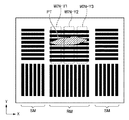
S216において、通知部60は、ユーザに対して、レチクルマークRMや基準マークSMを構成する複数のバーマークのうち、S212で選択されたバーマークの割合を通知する。換言すれば、通知部60は、複数のバーマークに占める一部のバーマーク、即ち、位置計測誤差が許容条件を満たすバーマークの割合を通知する。また、通知部60は、S212で選択されなかったバーマークの割合(バーマークの除去量)を通知してもよい。
In S216, the
例えば、図8に示すように、レチクルマークRMの非計測方向の全域にパーティクルPTが付着している場合がある。このような場合であっても、本実施形態では、レチクルアライメントをエラーとすることなく、オーバーレイ要求精度を満たすバーマークの位置からレチクルRの位置(ずれ量)を計測することができる。従って、露光装置1を停止させる頻度を低下させて、スループットを向上させることができる。
For example, as shown in FIG. 8, the particle PT may be attached to the entire area in the non-measurement direction of the reticle mark RM. Even in such a case, in the present embodiment, the position (displacement amount) of the reticle R can be measured from the position of the bar mark satisfying the overlay required accuracy without making the reticle alignment error. Therefore, the frequency of stopping the
<第3の実施形態>
図9を参照して、第3の実施形態における計測処理について説明する。本実施形態では、検出信号における複数の部分のそれぞれに関して、位置計測精度を評価し、検出信号における複数の部分のうち、位置計測精度が許容条件を満たす部分を選択し、かかる部分に基づいて、レチクルRの位置を得る。S301乃至S314のそれぞれは、第1の実施形態で説明したS101乃至S114のそれぞれと同様であるため、ここでの詳細な説明は省略する。
Third Embodiment
The measurement process in the third embodiment will be described with reference to FIG. In the present embodiment, the position measurement accuracy is evaluated for each of the plurality of portions in the detection signal, and among the plurality of portions in the detection signal, a portion where the position measurement accuracy satisfies the tolerance condition is selected. The position of the reticle R is obtained. Since each of S301 to S314 is the same as each of S101 to S114 described in the first embodiment, the detailed description here will be omitted.
S315において、誤差量推定部44は、S312で選択されていない計測窓、即ち、オーバーレイ要求精度を満たしていない計測窓の割合に基づいて、計測窓の減少に起因する計測再現性(の変化)Aを求める。本実施形態では、上述したように、レチクルマークRM及び基準マークSMのそれぞれを複数のバーマークで構成することで、平均化効果によって計測精度(計測再現性)を向上させている。但し、オーバーレイ要求精度を満たしていない計測窓を選択しないことで、その分の平均化効果が低減してしまう。例えば、全ての計測窓を選択したときの計測再現性が3σ=5nmである場合、半分の計測窓を選択したときの計測再現性Aは、A=5/√(50/100)=7.1nmとなる。なお、全ての計測窓を選択したときの計測再現性は、画像処理部40に予め記憶させておく必要がある。
In S315, the error
S316において、誤差量推定部44は、S312で選択された計測窓におけるレチクルマークRMや基準マークSMの誤差量の平均値Bを求める。これは、レチクルマークRMや基準マークSMの中心位置を求める際に発生しうる誤差量の平均値である。
In S316, the error
S317において、誤差量推定部44は、S315で求めた計測再現性Aと、S316で求めた平均値Bとに基づいて、レチクルアライメントにおけるトータルの誤差量Cを求める。例えば、誤差量推定部44は、計測再現性Aと平均値Bとの二乗和加算平方根、即ち、C=√(A2+B2)から、トータルの誤差量Cを求める。
In S317, the error
S318において、誤差量推定部44は、S317で求めたトータルの誤差量CがS301で設定されたオーバーレイ要求精度を満たしているかどうかを判定する。トータルの誤差量Cがオーバーレイ要求精度を満たしていない場合には、レチクルアライメントをエラーとして、処理を終了する。トータルの誤差量Cがオーバーレイ要求精度を満たしている場合には、S319に移行する。
In S318, the error
S319及びS320のそれぞれは、第1の実施形態で説明したS115及びS116のそれぞれと同様であるため、ここでの詳細な説明は省略する。但し、S320におけるS312で選択された計測窓の割合の通知は、検出信号に占める、位置計測精度が許容条件を満たす部分の割合を通知しているともいえる。 Since each of S319 and S320 is the same as each of S115 and S116 described in the first embodiment, the detailed description here will be omitted. However, it can be said that the notification of the ratio of the measurement window selected in S312 in S320 reports the ratio of the portion in the detection signal in which the position measurement accuracy satisfies the allowable condition.
本実施形態では、S307やS311で推定される誤差量の統計値(トータルの誤差量C)がオーバーレイ要求精度を満たす場合には、レチクルアライメントをエラーとすることなく、レチクルRの位置(ずれ量)を計測する。従って、計測再現性が低く、計測窓の割合がレチクルアライメントの精度(計測精度)に大きく寄与する場合であっても、オーバーレイ要求精度に応じて、レチクルアライメントを行うことができる。但し、計測再現性が十分に良好な場合には、本実施形態で得られる結果は、第1の実施形態で得られる結果とほぼ一致するため、処理時間の観点では、第3の実施形態よりも第1の実施形態の方が有利である。また、第3の実施形態は、第2の実施形態に適用することも可能である。 In the present embodiment, when the statistical value of the error amount estimated in S307 or S311 (total error amount C) satisfies the overlay required accuracy, the position of the reticle R (displacement amount) without making the reticle alignment error. Measure). Therefore, even if the measurement reproducibility is low and the ratio of the measurement window greatly contributes to the accuracy (measurement accuracy) of reticle alignment, reticle alignment can be performed according to the overlay required accuracy. However, when the measurement reproducibility is sufficiently good, the result obtained in the present embodiment substantially agrees with the result obtained in the first embodiment, so in view of the processing time, the third embodiment is more advantageous than the third embodiment. The first embodiment is also advantageous. The third embodiment can also be applied to the second embodiment.
<第4の実施形態>
図10を参照して、第4の実施形態における計測処理について説明する。S401乃至S403のそれぞれは、第1の実施形態で説明したS101乃至S103のそれぞれと同様であるため、ここでの詳細な説明は省略する。
Fourth Embodiment
The measurement process in the fourth embodiment will be described with reference to FIG. Since each of S401 to S403 is the same as each of S101 to S103 described in the first embodiment, the detailed description here will be omitted.
S404において、位置特定部43は、レチクルマークRMについて、S403で取得された画像における光量を非計測方向に積算して、図4に示すような1次元の積算波形を生成する。
In S404, the
S405において、位置特定部43は、S404で生成された積算波形に基づいて、例えば、重心計算処理やテンプレートマッチング処理などを用いて、レチクルマークRMの中心位置を求める。
In step S405, the
S406において、誤差量推定部44は、S405でレチクルマークRMの中心位置を求める際に発生しうる誤差量を推定する。換言すれば、誤差量推定部44は、S404で生成された積算波形(検出信号)に関して、位置計測誤差を評価する。
In S406, the error
S407において、位置特定部43は、S404と同様に、基準マークSMについて、S403で取得された画像における光量を非計測方向に積算して、1次元の積算波形を生成する。
In S407, the
S408において、位置特定部43は、S405と同様に、S407で生成された積算波形に基づいて、例えば、重心計算処理やテンプレートマッチング処理などを用いて、基準マークSMの中心位置を求める。
In S408, as in S405, the
S409において、誤差量推定部44は、S406と同様に、S408で基準マークSMの中心位置を求める際に発生しうる誤差量を推定する。換言すれば、誤差量推定部44は、S407で生成された積算波形(検出信号)に関して、位置計測誤差を評価する。
In S409, as in S406, the error
S410において、誤差量推定部44は、レチクルマークRM及び基準マークSMのそれぞれについて、S406及びS409のそれぞれで推定された誤差量がS401で設定されたオーバーレイ要求精度を満たしているかどうかを判定する。本実施形態において、誤差量推定部44は、レチクルマークRM及び基準マークSMのそれぞれの中心位置を求める際に発生しうる誤差量が計測精度に係る許容範囲内(オーバーレイ要求精度)を満たすかどうかを判定する。S406及びS409のそれぞれで推定された誤差量がオーバーレイ要求精度を満たしていない場合には、レチクルアライメントをエラーとして、処理を終了する。S406及びS409のそれぞれで推定された誤差量がオーバーレイ要求精度を満たしている場合には、S411に移行する。
In S410, the error
S411において、位置特定部43は、S405で求められたレチクルマークRMの中心位置及びS408で求められた基準マークSMの中心位置に基づいて、レチクルマークRMの位置と基準マークSMの位置との差を求める。ここで、レチクルマークRMの位置と基準マークSMの位置との差とは、上述したように、レチクルステージ11におけるレチクルRの位置(ずれ量)である。このように、本実施形態では、S406及びS409のそれぞれで推定された誤差量がS401で設定されるオーバーレイ要求精度を満たしている場合には、レチクルステージ11におけるレチクルRの位置を求める。
In step S411, the
S412において、通知部60は、ユーザに対して、S406及びS409のそれぞれで推定された誤差量(即ち、レチクルマークRM及び基準マークSMのそれぞれについての誤差量)を通知する。
In S412, the
このように、本実施形態では、レチクルマークRMや基準マークSMが形成されたマーク領域を複数の領域に分割することなく(即ち、複数の計測窓を設定することなく)、1次元の積算波形を生成してレチクルマークRMや基準マークSMの中心位置を求めている。具体的には、計測精度に係る許容条件(オーバーレイ要求精度)を検出信号が満たす場合、かかる検出信号に基づいてレチクルRの位置を得ている。従って、レチクルマークRMや基準マークSMへのパーティクルの付着などの頻度が低いプロセスにおいて、処理時間(レチクルアライメントに要する時間)を遅延させることなく、レチクルRの位置(ずれ量)を計測することができる。従って、露光装置1を停止させる頻度を低下させて、スループットを向上させることができる。
As described above, in this embodiment, the one-dimensional integrated waveform is obtained without dividing the mark area in which the reticle mark RM and the reference mark SM are formed into a plurality of areas (that is, without setting a plurality of measurement windows). To determine the center position of the reticle mark RM and the reference mark SM. Specifically, when the detection signal satisfies the tolerance condition (overlay required accuracy) relating to the measurement accuracy, the position of the reticle R is obtained based on the detection signal. Therefore, in a process with low frequency of adhesion of particles to reticle mark RM and reference mark SM, etc., the position (displacement amount) of reticle R can be measured without delaying the processing time (time required for reticle alignment). it can. Therefore, the frequency of stopping the
露光装置1は、例えば、半導体デバイス等のマイクロデバイスや微細構造を有する素子等の物品を製造するのに好適である。物品の製造方法は、基板に塗布された感光剤に露光装置1を用いて潜像パターンを形成する工程(パターン形成を基板に行う工程)と、かかる工程で潜像パターンを形成された基板を加工する工程(パターン形成を行われた基板を現像する工程)とを含む。更に、かかる製造方法は、他の周知の工程(酸化、成膜、蒸着、ドーピング、平坦化、エッチング、レジスト剥離、ダイシング、ボンディング、パッケージング等)を含みうる。本実施形態の物品の製造方法は、従来の方法に比べて、物品の性能・品質・生産性・生産コストの少なくとも1つにおいて有利である。
The
以上、本発明の好ましい実施形態について説明したが、本発明はこれらの実施形態に限定されないことはいうまでもなく、その要旨の範囲内で種々の変形及び変更が可能である。例えは、本発明では、対象物の位置としてレチクルステージにおけるレチクルの位置を例に説明したが、基板ステージにおける基板の位置を被計測物の位置としてもよい。 Although the preferred embodiments of the present invention have been described above, it goes without saying that the present invention is not limited to these embodiments, and various modifications and changes can be made within the scope of the present invention. For example, in the present invention, the position of the reticle on the reticle stage has been described as the position of the object, but the position of the substrate on the substrate stage may be the position of the object to be measured.
1:露光装置 14:制御部 20:計測装置 30:アライメントスコープ 40:画像処理部 42:領域分割部 43:位置特定部 44:誤差量推定部 R:レチクル W:基板 1: Exposure apparatus 14: Control unit 20: Measurement device 30: Alignment scope 40: Image processing unit 42: Region dividing unit 43: Position specifying unit 44: Error amount estimation unit R: Reticle W: Substrate
Claims (14)
前記対象物に形成されたマークの画像を取得する検出部と、
前記取得した画像から検出データを生成し、前記検出データに基づいて前記対象物の位置を得る処理部と、を有し、
前記処理部は、前記マークの領域が分割された前記画像の部分から複数の検出データを生成し、前記複数の検出データのそれぞれに対する位置計測誤差を評価し、前記複数の検出データから、前記評価した位置計測誤差に基づいて、前記計測装置による前記対象物の位置の計測に要求される精度の許容範囲に収まる部分を選択し、前記複数の検出データのうちの前記選択した部分に基づいて前記対象物の位置を得ることを特徴とする計測装置。 A measuring device that measures the position of an object, and
A detection unit that acquires an image of a mark formed on the object;
A processing unit that generates detection data from the acquired image and obtains the position of the object based on the detection data ;
The processing unit generates a plurality of detection data from the portion of the image in which the area of the mark is divided, and evaluates a position measurement error for each of the plurality of detection data, and the evaluation is performed from the plurality of detection data Based on the measured position measurement error, a portion that falls within an allowable range of accuracy required for measuring the position of the object by the measuring device is selected, and the selected portion of the plurality of detected data is selected. A measuring device characterized in that the position of an object is obtained.
前記選択された部分に対する計測再現性と、前記選択された部分に対する位置計測誤差量の平均値とに基づいて、トータルの誤差量を求め、前記トータルの誤差量が前記許容範囲を満たしているかどうかを判定し、
前記トータルの誤差量が前記許容範囲を満たしていない場合には、前記処理部は、前記選択した部分に基づいて前記対象物の位置を得ず、
前記トータルの誤差量が前記許容範囲を満たしている場合には、前記処理部は、前記選択した部分に基づいて前記対象物の位置を得る、
ことを特徴とする請求項1に記載の計測装置。 The processing unit is
Based on the measurement repeatability for the selected portion and the average value of the position measurement error amounts for the selected portion, a total error amount is determined, and whether the total error amount satisfies the allowable range To determine
If the total error amount does not satisfy the allowable range, the processing unit does not obtain the position of the object based on the selected portion.
When the total error amount satisfies the allowable range, the processing unit obtains the position of the object based on the selected portion .
The measuring device according to claim 1, characterized in that:
前記処理部は、前記マークの前記領域が前記第1方向に直交する方向に分割された前記画像の前記部分から前記複数の検出データを生成する、ことを特徴とする請求項1乃至3のうちいずれか1項に記載の計測装置。 The mark includes a plurality of mark elements arranged along a first direction,
Wherein the processing unit, the area of the mark to generate a plurality of detection data from the portion of the image that has been divided in a direction perpendicular to the first direction, of the claims 1 to 3, characterized in that The measuring device according to any one of the above.
前記処理部は、前記部分として、前記複数のマーク要素のうちの少なくとも1つを選択することを特徴とする請求項1乃至3のうちいずれか1項に記載の計測装置。 The mark includes a plurality of mark elements arranged along a first direction,
The measuring apparatus according to any one of claims 1 to 3 , wherein the processing unit selects at least one of the plurality of mark elements as the portion .
前記処理部は、前記部分として、前記複数の計測窓の少なくとも1つを選択することを特徴とする請求項1に記載の計測装置。The measuring apparatus according to claim 1, wherein the processing unit selects at least one of the plurality of measurement windows as the part.
前記対象物に形成されたマークを検出して検出信号を生成する検出部と、A detection unit that detects a mark formed on the object and generates a detection signal;
前記検出信号に基づいて前記対象物の位置を得る処理部と、を有し、A processing unit for obtaining the position of the object based on the detection signal;
前記処理部は、前記対象物に対する計測精度に係る許容条件に関する情報に基づいて限定された前記検出信号のうちの部分に基づいて前記対象物の位置を得、The processing unit obtains the position of the object based on a portion of the detection signal limited based on information on an allowable condition related to measurement accuracy with respect to the object.
前記計測装置は、前記検出信号に占める前記部分の割合を通知する通知部を更に有することを特徴とする計測装置。The measuring apparatus according to claim 1, further comprising: a notification unit configured to notify a proportion of the portion in the detection signal.
前記対象物に形成されたマークを検出して検出信号を生成する検出部と、A detection unit that detects a mark formed on the object and generates a detection signal;
前記検出信号のうちの複数の部分のそれぞれに関して、位置計測精度を評価し、前記対象物に対する計測精度に係る許容条件に関する情報に基づいて、前記位置計測精度が許容条件を満たす、前記複数の部分のうちの部分を選択し、該部分に基づいて、前記対象物の位置を得る処理部と、を有し、Position measurement accuracy is evaluated for each of a plurality of portions of the detection signal, and the plurality of portions where the position measurement accuracy satisfies an allowance condition based on information on an allowance condition related to the measurement accuracy for the object A processing unit for selecting a part of the above and obtaining the position of the object based on the part;
前記マークは、第1方向に沿って配列された複数のマーク要素を含み、The mark includes a plurality of mark elements arranged along a first direction,
前記処理部は、前記複数のマーク要素のうちの一部のマーク要素に対応する、前記位置計測精度が許容条件を満たす前記部分に基づいて、前記対象物の位置を得、The processing unit obtains the position of the object based on the part corresponding to a part of mark elements among the plurality of mark elements, the position measurement accuracy satisfying an allowable condition,
前記計測装置は、前記複数のマーク要素に占める前記一部のマーク要素の割合を通知する通知部を有することを特徴とする計測装置。The measurement apparatus according to claim 1, further comprising: a notification unit configured to notify a proportion of the part of the mark elements in the plurality of mark elements.
前記対象物を保持して可動の保持部と、
前記対象物の位置を計測する請求項1乃至11のうちいずれか1項に記載の計測装置と、
を有することを特徴とするリソグラフィ装置。 A lithographic apparatus for patterning an object, comprising:
A movable holding unit that holds the object;
The measuring device according to any one of claims 1 to 11, which measures the position of the object.
A lithographic apparatus comprising:
前記工程で前記パターン形成を行われた前記基板を加工する工程と、
を含むことを特徴とする物品の製造方法。 A process of forming a pattern on a substrate using the lithographic apparatus according to claim 12 or 13;
Processing the substrate on which the pattern formation has been performed in the step;
A method of producing an article comprising:
Priority Applications (4)
| Application Number | Priority Date | Filing Date | Title |
|---|---|---|---|
| JP2015003608A JP6521637B2 (en) | 2015-01-09 | 2015-01-09 | Measurement apparatus, lithographic apparatus, and method of manufacturing article |
| TW104141149A TWI621000B (en) | 2015-01-09 | 2015-12-08 | Measurement apparatus, lithography apparatus, and method of manufacturing article |
| US14/973,888 US10185235B2 (en) | 2015-01-09 | 2015-12-18 | Measurement apparatus, lithography apparatus, and method of manufacturing article |
| KR1020150189157A KR101993951B1 (en) | 2015-01-09 | 2015-12-30 | Measurement apparatus, lithography apparatus, and method of manufacturing article |
Applications Claiming Priority (1)
| Application Number | Priority Date | Filing Date | Title |
|---|---|---|---|
| JP2015003608A JP6521637B2 (en) | 2015-01-09 | 2015-01-09 | Measurement apparatus, lithographic apparatus, and method of manufacturing article |
Publications (3)
| Publication Number | Publication Date |
|---|---|
| JP2016129212A JP2016129212A (en) | 2016-07-14 |
| JP2016129212A5 JP2016129212A5 (en) | 2018-02-15 |
| JP6521637B2 true JP6521637B2 (en) | 2019-05-29 |
Family
ID=56367503
Family Applications (1)
| Application Number | Title | Priority Date | Filing Date |
|---|---|---|---|
| JP2015003608A Active JP6521637B2 (en) | 2015-01-09 | 2015-01-09 | Measurement apparatus, lithographic apparatus, and method of manufacturing article |
Country Status (4)
| Country | Link |
|---|---|
| US (1) | US10185235B2 (en) |
| JP (1) | JP6521637B2 (en) |
| KR (1) | KR101993951B1 (en) |
| TW (1) | TWI621000B (en) |
Families Citing this family (5)
| Publication number | Priority date | Publication date | Assignee | Title |
|---|---|---|---|---|
| CN107976870B (en) * | 2016-10-24 | 2020-12-04 | 上海微电子装备(集团)股份有限公司 | Motion platform positioning error compensation device and compensation method |
| US10156439B2 (en) * | 2017-03-03 | 2018-12-18 | The Boeing Company | Inspection system for alignment in restricted volumes |
| US11175598B2 (en) * | 2017-06-30 | 2021-11-16 | Canon Kabushiki Kaisha | Imprint apparatus and method of manufacturing article |
| CN111123662B (en) * | 2020-01-19 | 2022-04-26 | 中国科学院微电子研究所 | Method and device for acquiring overlay error measurement data |
| CN112408316B (en) * | 2020-11-20 | 2024-04-12 | 中国科学院上海微系统与信息技术研究所 | Preparation method of double-sided super-surface structure |
Family Cites Families (21)
| Publication number | Priority date | Publication date | Assignee | Title |
|---|---|---|---|---|
| JP3391328B2 (en) * | 1993-02-08 | 2003-03-31 | 株式会社ニコン | Alignment method, exposure method using the alignment method, device manufacturing method using the exposure method, device manufactured by the device manufacturing method, alignment apparatus, and exposure apparatus including the alignment apparatus |
| JP3594221B2 (en) | 1999-01-26 | 2004-11-24 | シャープ株式会社 | Test circuit for semiconductor integrated circuit device |
| JP2001267206A (en) * | 2000-03-15 | 2001-09-28 | Canon Inc | Alignment method, aligner, and method for producing semiconductor device |
| JP2001319858A (en) * | 2000-05-09 | 2001-11-16 | Canon Inc | Alignment-mark position measuring method, pattern exposure system, semiconductor device manufacturing method, semiconductor manufacturing plant, and pattern exposure system maintaining method |
| JP4272862B2 (en) | 2002-09-20 | 2009-06-03 | キヤノン株式会社 | Position detection method, position detection apparatus, and exposure apparatus |
| JP2004235354A (en) | 2003-01-29 | 2004-08-19 | Canon Inc | Aligner |
| JP2005057222A (en) * | 2003-08-07 | 2005-03-03 | Canon Inc | Mark detection device, method, and program, and aligner, method for manufacturing device, and device |
| KR20050120072A (en) | 2004-06-18 | 2005-12-22 | 동부아남반도체 주식회사 | Alignment mark in semiconductor device and method for aligning substrate using the same |
| US7436485B2 (en) | 2005-04-06 | 2008-10-14 | Asml Netherlands B.V. | Lithographic apparatus, patterning assembly and contamination estimation method |
| US7408618B2 (en) | 2005-06-30 | 2008-08-05 | Asml Netherlands B.V. | Lithographic apparatus substrate alignment |
| JP2007103658A (en) | 2005-10-04 | 2007-04-19 | Canon Inc | Method and device for exposure as well as method of manufacturing device |
| JP5002221B2 (en) | 2006-09-11 | 2012-08-15 | キヤノン株式会社 | Device for detecting the position of a mark |
| JP5132277B2 (en) | 2006-12-04 | 2013-01-30 | キヤノン株式会社 | Measuring apparatus, exposure apparatus, and device manufacturing method |
| JP4307482B2 (en) | 2006-12-19 | 2009-08-05 | キヤノン株式会社 | Position measuring apparatus, exposure apparatus, and device manufacturing method |
| JP2008205393A (en) * | 2007-02-22 | 2008-09-04 | Canon Inc | Method and lithography for deciding condition of position detection for alignment mark, and method for manufacturing device |
| CN100480867C (en) * | 2007-03-06 | 2009-04-22 | 上海微电子装备有限公司 | Aligning system and aligning method based on image technique |
| DE102008004762A1 (en) * | 2008-01-16 | 2009-07-30 | Carl Zeiss Smt Ag | Projection exposure apparatus for microlithography with a measuring device |
| JP5096965B2 (en) * | 2008-02-29 | 2012-12-12 | キヤノン株式会社 | Alignment method, alignment apparatus, exposure method, and device manufacturing method |
| DE102008015631A1 (en) * | 2008-03-20 | 2009-09-24 | Carl Zeiss Sms Gmbh | Method and device for measuring masks for photolithography |
| US9360778B2 (en) * | 2012-03-02 | 2016-06-07 | Taiwan Semiconductor Manufacturing Company, Ltd. | System and method for lithography patterning |
| JP6386732B2 (en) | 2014-01-20 | 2018-09-05 | キヤノン株式会社 | Detection apparatus, detection method, and lithography apparatus |
-
2015
- 2015-01-09 JP JP2015003608A patent/JP6521637B2/en active Active
- 2015-12-08 TW TW104141149A patent/TWI621000B/en active
- 2015-12-18 US US14/973,888 patent/US10185235B2/en active Active
- 2015-12-30 KR KR1020150189157A patent/KR101993951B1/en active IP Right Grant
Also Published As
| Publication number | Publication date |
|---|---|
| US10185235B2 (en) | 2019-01-22 |
| US20160202620A1 (en) | 2016-07-14 |
| TW201626118A (en) | 2016-07-16 |
| TWI621000B (en) | 2018-04-11 |
| JP2016129212A (en) | 2016-07-14 |
| KR20160086273A (en) | 2016-07-19 |
| KR101993951B1 (en) | 2019-06-27 |
Similar Documents
| Publication | Publication Date | Title |
|---|---|---|
| US7355187B2 (en) | Position detection apparatus, position detection method, exposure apparatus, device manufacturing method, and substrate | |
| JP6521637B2 (en) | Measurement apparatus, lithographic apparatus, and method of manufacturing article | |
| US20040239905A1 (en) | Lithographic apparatus, system, method, computer program, and apparatus for height map analysis | |
| KR20080059572A (en) | Optical characteristic measuring method, exposure method, device manufacturing method, inspecting apparatus and measuring method | |
| KR101867648B1 (en) | Method of obtaining position, exposure method, and method of manufacturing article | |
| JP2018072541A (en) | Pattern formation method, positioning method of substrate, positioning device, pattern formation device and manufacturing method of article | |
| US9910371B2 (en) | Exposure apparatus, exposure method, and device manufacturing method | |
| JP2005030963A (en) | Position detecting method | |
| CN114624969A (en) | Detection apparatus and method, exposure apparatus, exposure system, and article manufacturing method | |
| KR102493922B1 (en) | Determination method, exposure method, exposure apparatus, method of manufacturing article, and computer program | |
| CN112309909B (en) | Judgment device, substrate processing device, and method for manufacturing article | |
| JP4040668B2 (en) | Position detection apparatus and method, exposure apparatus, and device manufacturing method | |
| CN110209016B (en) | Exposure apparatus, exposure method, and method of manufacturing article | |
| JP6185724B2 (en) | Exposure apparatus and article manufacturing method | |
| JP6371602B2 (en) | Exposure apparatus, exposure method, and article manufacturing method | |
| TWI678726B (en) | Patterning method, lithography apparatus, and article manufacturing method | |
| JP2011049400A (en) | Position detector, exposure device and manufacturing method of device | |
| JP2020177149A (en) | Exposure apparatus and method for manufacturing article | |
| JP7373340B2 (en) | judgment device | |
| JP5922927B2 (en) | Method for determining position, information processing apparatus, lithography apparatus, and article manufacturing method | |
| JP4733857B2 (en) | Scanning system and method for measuring reticle CD in integrated circuit manufacturing | |
| KR20220040380A (en) | Control method of lithography apparatus, lithography apparatus and article manufacturing method | |
| TW202314403A (en) | Exposure apparatus and method for manufacturing article capable of accurately adjusting focus with a small size and simple structure while maintaining an improved throughput | |
| JP2020095218A (en) | Determination method, exposure method, method for manufacturing article, and program | |
| JP2016062921A (en) | Exposure device and device manufacturing method |
Legal Events
| Date | Code | Title | Description |
|---|---|---|---|
| A521 | Request for written amendment filed |
Free format text: JAPANESE INTERMEDIATE CODE: A523 Effective date: 20171219 |
|
| A621 | Written request for application examination |
Free format text: JAPANESE INTERMEDIATE CODE: A621 Effective date: 20171219 |
|
| A977 | Report on retrieval |
Free format text: JAPANESE INTERMEDIATE CODE: A971007 Effective date: 20181120 |
|
| A131 | Notification of reasons for refusal |
Free format text: JAPANESE INTERMEDIATE CODE: A131 Effective date: 20181130 |
|
| A521 | Request for written amendment filed |
Free format text: JAPANESE INTERMEDIATE CODE: A523 Effective date: 20190118 |
|
| TRDD | Decision of grant or rejection written | ||
| A01 | Written decision to grant a patent or to grant a registration (utility model) |
Free format text: JAPANESE INTERMEDIATE CODE: A01 Effective date: 20190326 |
|
| A61 | First payment of annual fees (during grant procedure) |
Free format text: JAPANESE INTERMEDIATE CODE: A61 Effective date: 20190423 |
|
| R151 | Written notification of patent or utility model registration |
Ref document number: 6521637 Country of ref document: JP Free format text: JAPANESE INTERMEDIATE CODE: R151 |