JP6520539B2 - Search system - Google Patents
Search system Download PDFInfo
- Publication number
- JP6520539B2 JP6520539B2 JP2015154968A JP2015154968A JP6520539B2 JP 6520539 B2 JP6520539 B2 JP 6520539B2 JP 2015154968 A JP2015154968 A JP 2015154968A JP 2015154968 A JP2015154968 A JP 2015154968A JP 6520539 B2 JP6520539 B2 JP 6520539B2
- Authority
- JP
- Japan
- Prior art keywords
- similarity
- signal
- signals
- signal group
- trace data
- Prior art date
- Legal status (The legal status is an assumption and is not a legal conclusion. Google has not performed a legal analysis and makes no representation as to the accuracy of the status listed.)
- Active
Links
Images


Classifications
-
- B—PERFORMING OPERATIONS; TRANSPORTING
- B66—HOISTING; LIFTING; HAULING
- B66B—ELEVATORS; ESCALATORS OR MOVING WALKWAYS
- B66B5/00—Applications of checking, fault-correcting, or safety devices in elevators
- B66B5/0006—Monitoring devices or performance analysers
- B66B5/0018—Devices monitoring the operating condition of the elevator system
- B66B5/0025—Devices monitoring the operating condition of the elevator system for maintenance or repair
-
- G—PHYSICS
- G05—CONTROLLING; REGULATING
- G05B—CONTROL OR REGULATING SYSTEMS IN GENERAL; FUNCTIONAL ELEMENTS OF SUCH SYSTEMS; MONITORING OR TESTING ARRANGEMENTS FOR SUCH SYSTEMS OR ELEMENTS
- G05B23/00—Testing or monitoring of control systems or parts thereof
- G05B23/02—Electric testing or monitoring
- G05B23/0205—Electric testing or monitoring by means of a monitoring system capable of detecting and responding to faults
- G05B23/0259—Electric testing or monitoring by means of a monitoring system capable of detecting and responding to faults characterized by the response to fault detection
- G05B23/0275—Fault isolation and identification, e.g. classify fault; estimate cause or root of failure
-
- B—PERFORMING OPERATIONS; TRANSPORTING
- B66—HOISTING; LIFTING; HAULING
- B66B—ELEVATORS; ESCALATORS OR MOVING WALKWAYS
- B66B5/00—Applications of checking, fault-correcting, or safety devices in elevators
-
- G—PHYSICS
- G05—CONTROLLING; REGULATING
- G05B—CONTROL OR REGULATING SYSTEMS IN GENERAL; FUNCTIONAL ELEMENTS OF SUCH SYSTEMS; MONITORING OR TESTING ARRANGEMENTS FOR SUCH SYSTEMS OR ELEMENTS
- G05B23/00—Testing or monitoring of control systems or parts thereof
- G05B23/02—Electric testing or monitoring
- G05B23/0205—Electric testing or monitoring by means of a monitoring system capable of detecting and responding to faults
- G05B23/0218—Electric testing or monitoring by means of a monitoring system capable of detecting and responding to faults characterised by the fault detection method dealing with either existing or incipient faults
- G05B23/0224—Process history based detection method, e.g. whereby history implies the availability of large amounts of data
- G05B23/0227—Qualitative history assessment, whereby the type of data acted upon, e.g. waveforms, images or patterns, is not relevant, e.g. rule based assessment; if-then decisions
- G05B23/0229—Qualitative history assessment, whereby the type of data acted upon, e.g. waveforms, images or patterns, is not relevant, e.g. rule based assessment; if-then decisions knowledge based, e.g. expert systems; genetic algorithms
-
- G—PHYSICS
- G05—CONTROLLING; REGULATING
- G05B—CONTROL OR REGULATING SYSTEMS IN GENERAL; FUNCTIONAL ELEMENTS OF SUCH SYSTEMS; MONITORING OR TESTING ARRANGEMENTS FOR SUCH SYSTEMS OR ELEMENTS
- G05B23/00—Testing or monitoring of control systems or parts thereof
- G05B23/02—Electric testing or monitoring
- G05B23/0205—Electric testing or monitoring by means of a monitoring system capable of detecting and responding to faults
- G05B23/0218—Electric testing or monitoring by means of a monitoring system capable of detecting and responding to faults characterised by the fault detection method dealing with either existing or incipient faults
- G05B23/0224—Process history based detection method, e.g. whereby history implies the availability of large amounts of data
- G05B23/0227—Qualitative history assessment, whereby the type of data acted upon, e.g. waveforms, images or patterns, is not relevant, e.g. rule based assessment; if-then decisions
- G05B23/0235—Qualitative history assessment, whereby the type of data acted upon, e.g. waveforms, images or patterns, is not relevant, e.g. rule based assessment; if-then decisions based on a comparison with predetermined threshold or range, e.g. "classical methods", carried out during normal operation; threshold adaptation or choice; when or how to compare with the threshold
-
- G—PHYSICS
- G06—COMPUTING; CALCULATING OR COUNTING
- G06F—ELECTRIC DIGITAL DATA PROCESSING
- G06F16/00—Information retrieval; Database structures therefor; File system structures therefor
Description
この発明は、故障の原因等を推定するために利用可能な検索システムに関する。 The present invention relates to a search system that can be used to estimate the cause of a failure.
特許文献1に、プラントで発生した異常を検知するためのシステムが記載されている。特許文献1に記載されたシステムでは、取得したデータと学習データを部分空間法でモデル化した部分空間との距離関係に基づいて、取得したデータの異常を検知する。
例えば、エレベータで故障が発生すると、故障発生前後のある一定時間に対して、エレベータに備えられた多数のセンサの状態を示す信号値のスナップショットを取得する。この信号値のスナップショットを本明細書ではトレースデータと称する。従来では、新たなトレースデータが取得された場合に、このトレースデータに類似する過去のトレースデータを検索することができなかった。このような検索は、例えばトレースデータから故障原因を推定するために有用である。 For example, when a failure occurs in the elevator, a snapshot of signal values indicating the states of a large number of sensors provided in the elevator is acquired for a certain period of time before and after the failure occurrence. A snapshot of this signal value is referred to herein as trace data. Conventionally, when new trace data is acquired, it is not possible to search past trace data similar to the trace data. Such a search is useful, for example, to estimate the cause of failure from trace data.
この発明は、上述のような課題を解決するためになされた。この発明の目的は、複数の信号を含む信号群に類似する信号群を簡単な構成によって検索できる検索システムを提供することである。 The present invention has been made to solve the problems as described above. An object of the present invention is to provide a search system capable of searching for a signal group similar to a signal group including a plurality of signals with a simple configuration.
この発明に係る検索システムは、複数の信号を含む第1信号群を読み込む読込手段と、複数の信号を含む第2信号群が記憶された記憶手段と、読込手段によって読み込まれた第1信号群に含まれる信号と記憶手段に記憶された第2信号群に含まれる信号のうち第1信号群に含まれる当該信号に対応する信号との類似度を、第1信号群に含まれる複数の信号について算出する第1類似度算出手段と、第1類似度算出手段によって算出された複数の類似度に基づいて、読込手段によって読み込まれた第1信号群と記憶手段に記憶された第2信号群との類似度を算出する第2類似度算出手段と、前記記憶手段に記憶された第2信号群に含まれる信号の中から除外信号を特定する特定手段と、を備える。記憶手段に複数の第2信号群が記憶される。第1類似度算出手段は、読込手段によって読み込まれた第1信号群と記憶手段に記憶された各第2信号群とについて信号間の類似度を算出する。第2類似度算出手段は、読込手段によって読み込まれた第1信号群と記憶手段に記憶された各第2信号群との類似度を算出する。第1信号群及び各第2信号群は、エレベータに備えられた複数のセンサからの信号を含む。各第2信号群は、エレベータの故障箇所を示す故障情報と紐付けて記憶手段に記憶される。特定手段は、同じ故障情報が紐付けられた第2信号群について対応する信号間の類似度を算出し、その故障情報について類似度のばらつきが閾値を超える信号を特定し、全ての故障情報について類似度のばらつきが閾値を超える信号を除外信号に特定する。第1類似度算出手段は、特定手段によって特定された除外信号については、信号間の類似度を算出しない。
The search system according to the present invention comprises: reading means for reading a first signal group including a plurality of signals; storage means storing a second signal group including a plurality of signals; and a first signal group read by the reading means , And a plurality of signals included in the first signal group between the signals included in the second signal group stored in the storage means and the signals corresponding to the signals included in the first signal group among the signals included in the second signal group The first signal group read by the reading means and the second signal group stored in the storage means, based on the first similarity degree calculating means for calculating for and the plurality of similarity degrees calculated by the first similarity degree calculating means And a specifying unit for specifying an exclusion signal from among the signals included in the second signal group stored in the storage unit . A plurality of second signal groups are stored in the storage means. The first similarity calculation means calculates the similarity between the signals for the first signal group read by the reading means and each second signal group stored in the storage means. The second similarity calculation means calculates the similarity between the first signal group read by the reading means and each second signal group stored in the storage means. The first signal group and the second signal group includes signals from a plurality of sensors provided in the elevators. Each of the second signal group is stored in the fault information and straps attached to the storage means for indicating the fault location of the elevators. The identification means calculates the similarity between the corresponding signals for the second signal group to which the same fault information is linked, identifies the signal whose variation in similarity exceeds the threshold for the fault information, and for all fault information A signal whose variation in similarity exceeds a threshold is specified as an exclusion signal. The first similarity calculation means does not calculate the similarity between the signals for the excluded signals specified by the specifying means.
この発明に係る検索システムであれば、複数の信号を含む信号群に類似する信号群を簡単な構成によって検索できる。 According to the search system of the present invention, a signal group similar to a signal group including a plurality of signals can be searched with a simple configuration.
添付の図面を参照し、本発明を説明する。重複する説明は、適宜簡略化或いは省略する。各図において、同一の符号は同一の部分又は相当する部分を示す。 The invention will be described with reference to the accompanying drawings. Duplicate descriptions will be simplified or omitted as appropriate. In each figure, the same numerals show the same portion or the corresponding portion.
実施の形態1.
図1は、この発明の実施の形態1における検索システムの構成例を示す図である。検索装置1は、遠隔の多数のエレベータ装置と通信が可能である。各エレベータ装置は、例えばかご2及びつり合いおもり3を備える。かご2及びつり合いおもり3は、主ロープ4によって昇降路に吊り下げられる。エレベータの巻上機は、例えば駆動綱車5及び電動機6を備える。駆動綱車5に主ロープ4が巻き掛けられる。駆動綱車5は、電動機6によって駆動される。電動機6は、制御盤7によって制御される。制御盤7に通信装置8が接続される。通信装置8は、外部の機器との通信を行う。各エレベータ装置は、通信装置8によって検索装置1と通信する。
FIG. 1 is a diagram showing an example of the configuration of a search system according to
エレベータ装置で何らかの故障が発生すると、故障発生前後のある一定時間に対して、エレベータに備えられた多数のセンサの状態を示す信号値のスナップショット(トレースデータ)が通信装置8によって取得される。例えば、トレースデータには、エレベータ装置自体を特定するための信号、時刻を示す信号、制御盤7の電流値及び電圧値を示す信号、電動機6の速度及びトルクを示す信号、ドアの開閉状態を示す信号、かご2の位置を示す信号、及び安全装置の動作状態を示す信号等が含まれる。トレースデータに含まれる信号は、上記例に限定されない。例示した信号の一部がトレースデータに含まれなくても良い。トレースデータに他の信号が含まれても良い。
When any failure occurs in the elevator apparatus, snapshots (trace data) of signal values indicating the states of a large number of sensors provided in the elevator are acquired by the
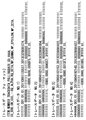
図2は、トレースデータの例を示す図である。図2は、4つのトレースデータの例を示す。トレースデータに含まれる信号の表記は、1種類に限定されない。例えば、2進数で表記される信号、16進数で表記される信号及び10進数で表記される信号がトレースデータに混在しても良い。また、いろいろな信号長の信号がトレースデータに混在しても良い。通信装置8は、トレースデータを取得すると、取得したトレースデータを検索装置1に送信する。
FIG. 2 is a diagram showing an example of trace data. FIG. 2 shows an example of four trace data. The representation of signals included in trace data is not limited to one type. For example, a signal represented by a binary number, a signal represented by a hexadecimal number, and a signal represented by a decimal number may be mixed in the trace data. Also, signals of various signal lengths may be mixed in the trace data. When the
検索装置1は、例えば記憶部9、読込部10、第1類似度算出部11、第2類似度算出部12、表示制御部13及び表示器15を備える。以下に、図3から図6も参照し、検索装置1の機能及び動作について説明する。図3は、この発明の実施の形態1における検索システムの動作例を示すフローチャートである。
The
読込部10は、トレースデータを読み込む。検索装置1に接続された何れかのエレベータ装置で故障が発生すると、そのエレベータ装置の通信装置8から故障発生時のトレースデータが送信される。通信装置8から送信されたトレースデータは、読込部10によって読み込まれる(S101)。読込部10が読み込むトレースデータには多数の信号が含まれる。トレースデータに含まれる信号の順番は、予め定められている。
The
記憶部9に、読込部10によって過去に読み込まれた複数のトレースデータが記憶される。即ち、読込部10によって読み込まれたトレースデータは、記憶部9に蓄積されていく。以下の説明では、読込部10によって新たに読み込まれたトレースデータを「トレースデータA」と表記する。記憶部9に記憶された過去のトレースデータを「トレースデータB」と表記する。記憶部9には、多数のトレースデータBが記憶される。
The
第1類似度算出部11は、トレースデータAに含まれる信号とトレースデータBに含まれる信号との類似度を算出する(S102)。トレースデータAに含まれる信号の種類は、トレースデータBに含まれる信号の種類と基本的に同じである。トレースデータA及びトレースデータBには、対応する信号が含まれる。第1類似度算出部11は、トレースデータA及びトレースデータBにおいて、対応する信号間の類似度を算出する。即ち、第1類似度算出部11は、トレースデータAに含まれるある信号とトレースデータBに含まれる信号のうちトレースデータAに含まれる当該信号に対応する信号との類似度を算出する。
The first
第1類似度算出部11は、トレースデータAに含まれる各信号について、トレースデータBに含まれる信号との類似度を算出する。例えば、第1類似度算出部11は、トレースデータAに含まれるトルク信号とトレースデータBに含まれるトルク信号との類似度を算出する。他の例として、第1類似度算出部11は、トレースデータAに含まれるドア開閉信号とトレースデータBに含まれるドア開閉信号との類似度を算出する。
The first
図4及び図5は、第1類似度算出部11の機能を説明するための図である。第1類似度算出部11は、例えば、動的計画法(DPマッチング)を用いて信号間の類似度を算出する。例えば、トレースデータAに含まれるある信号(00001111)とその信号に対応するトレースデータBに含まれる信号(00000111)とを比較する場合を考える。動的計画法による類似度の算出は、図4及び図5に示すように一方の信号を縦に、他方の信号を横に並べ、移動ペナルティと不一致ペナルティとを考慮しながら左上の桝目から右下の桝目に値を入力していくことよって行われる。そして、左上の桝目から右下の桝目に向かってペナルティが最小となる経路を探索する。
FIG. 4 and FIG. 5 are diagrams for explaining the function of the first
図4に示す例では、右方向の移動ペナルティを+1、下方向の移動ペナルティを+1、右下への斜め方向の移動ペナルティを0に設定している。また、値が一致する場合のペナルティを0、値が不一致の場合のペナルティを+1に設定している。この場合、上記信号間の類似度は1と算出される。図5に示す例では、右方向の移動ペナルティを+1、下方向の移動ペナルティを+1、右下への斜め方向の移動ペナルティを0に設定している。また、値が一致する場合のペナルティを0、値が不一致の場合のペナルティを+3に設定している。この場合、上記信号間の類似度は2と算出される。図4及び図5に示す例では、比較する信号同士が似ている程、第1類似度算出部11によって算出される類似度の値は小さくなる。なお、移動ペナルティの設定方法及び不一致ペナルティの設定方法は、これらの例に限定されない。また、第1類似度算出部11が類似度を算出する方法は、動的計画法に限定されない。
In the example shown in FIG. 4, the movement penalty in the right direction is set to +1, the movement penalty in the lower direction is set to +1, and the movement penalty in the diagonal direction to the lower right is set to zero. In addition, the penalty when the values match is set to 0, and the penalty when the values do not match is set to +1. In this case, the similarity between the signals is calculated as 1. In the example shown in FIG. 5, the movement penalty in the right direction is set to +1, the movement penalty in the lower direction is set to +1, and the movement penalty in the diagonal direction to the lower right is set to zero. In addition, the penalty when the values match is set to 0, and the penalty when the values do not match to +3. In this case, the similarity between the signals is calculated as 2. In the example shown in FIG. 4 and FIG. 5, the value of the similarity calculated by the first
第2類似度算出部12は、トレースデータAとトレースデータBとの類似度を算出する(S103)。第2類似度算出部12は、第1類似度算出部11によって算出された複数の類似度に基づいて上記算出を行う。例えば、トレースデータA及びトレースデータBのそれぞれに100個の信号が含まれている場合、第1類似度算出部11によって各信号の類似度が算出される。即ち、第1類似度算出部11は、100個の類似度を算出する。第2類似度算出部12は、第1類似度算出部11によって算出された100個の類似度に基づいて上記算出を行う。
The second
例えば、第2類似度算出部12は、次式によってトレースデータAとトレースデータBとの距離Lを算出する。Liは信号iの類似度、NはトレースデータA(或いは、トレースデータB)に含まれる信号数である。
For example, the second

第2類似度算出部12は、式1によって求めた距離Lを用いて、トレースデータAとトレースデータBとの類似度Pmatchを次式によって算出する。
The second
Lmaxは、トレースデータAとトレースデータBとの距離Lの最大値である。Lmaxは、例えば全ての信号の値が1であるトレースデータAと全ての信号の値が0であるトレースデータBとの距離に相当する。なお、第2類似度算出部12が類似度を算出する方法は、上記例に限定されない。
L max is the maximum value of the distance L between the trace data A and the trace data B. L max corresponds, for example, to the distance between the trace data A in which the values of all the signals are 1 and the trace data B in which the values of all the signals are 0. The method by which the second
記憶部9には、複数のトレースデータBが記憶されている。検索装置1では、トレースデータAと各トレースデータBとの類似度を算出する。このため、検索装置1では、トレースデータAと1つのトレースデータBとの類似度が算出されると、全てのトレースデータBについて類似度が算出されたか否かを判定する(S104)。トレースデータAとの類似度が算出されていないトレースデータBがあれば(S104のNo)、そのトレースデータBに対してS102の処理とS103の処理とが行われる。即ち、第1類似度算出部11は、トレースデータAに含まれる信号とそのトレースデータBに含まれる信号との類似度を算出する。第2類似度算出部12は、トレースデータAとそのトレースデータBとの類似度を算出する。
The
表示制御部13は、表示器15を制御する。トレースデータAと各トレースデータBとの類似度が算出されると(S104のYes)、表示制御部13は、第2類似度算出部12による算出結果を表示器15に表示させる。例えば、表示制御部13は、第2類似度算出部12によって算出された類似度順に、トレースデータBを示す情報を表示器15に表示させる(S105)。
The
図6は、表示器15の表示例を示す図である。図6は、表示制御部13が、第2類似度算出部12によって算出された類似度が高い順にトレースデータBを特定する情報を表示器15に表示させる例を示す。また、図6は、トレースデータBを特定する情報として、故障が発生した日時と故障が発生したエレベータ装置とを示す情報が表示器15に表示される例を示す。表示器15に表示される情報は、図6に示す例に限定されない。
FIG. 6 is a view showing a display example of the
上記構成を有する検索システムであれば、複数の信号を含む信号群に類似する信号群を簡単な構成によって検索できる。エレベータの監視員及び保守員は、表示器15に表示されたトレースデータBの内容を精査することにより、トレースデータAを送信してきたエレベータ装置で発生した故障の原因を推定することができる。
With the search system having the above configuration, a signal group similar to a signal group including a plurality of signals can be searched with a simple configuration. By monitoring the contents of the trace data B displayed on the
本実施の形態では、検索装置1が表示器15を備える例について説明した。表示器15は、外部の装置に備えられても良い。かかる場合、表示制御部13は、第2類似度算出部12による算出結果を表示器15に表示させるための情報を外部の装置に送信する。
In the present embodiment, an example in which the
本実施の形態では、第2類似度算出部12による算出結果を表示器15に表示させる例について説明した。これは一例である。エレベータの監視員或いは保守員が第2類似度算出部12による算出結果を後から利用することができるように、第2類似度算出部12による算出結果を検索装置1内に保存しておいても良い。
In the present embodiment, an example in which the calculation result by the second
本実施の形態では、第1類似度算出部11が動的計画法を用いて信号間の類似度を算出する例について説明した。トレースデータAには、例えば、信号長が異なる複数の信号が含まれる。この場合、各トレースデータBにも信号長が異なる複数の信号が含まれる。本実施の形態で開示した類似度の算出方法では、第1類似度算出部11が算出する類似度の最大値が信号長に依存する。
In the present embodiment, an example has been described in which the first
図7は、信号間の類似度の最大値が信号長に依存する例を示す図である。図7に示す例では、図4に示す例と同様に、右方向の移動ペナルティを+1、下方向の移動ペナルティを+1、右下への斜め方向の移動ペナルティを0に設定している。また、値が一致する場合のペナルティを0、値が不一致の場合のペナルティを+1に設定している。図7に示すように、信号長が2である信号間の類似度の最大値は2となる。一方、信号長が8である信号間の類似度の最大値は8となる。 FIG. 7 is a diagram showing an example in which the maximum value of the similarity between signals depends on the signal length. In the example shown in FIG. 7, similarly to the example shown in FIG. 4, the movement penalty in the right direction is set to +1, the movement penalty in the downward direction is +1, and the movement penalty in the diagonal direction to the lower right is set to zero. In addition, the penalty when the values match is set to 0, and the penalty when the values do not match is set to +1. As shown in FIG. 7, the maximum value of similarity between signals having a signal length of 2 is 2. On the other hand, the maximum value of the similarity between the signals having a signal length of 8 is 8.
第1類似度算出部11は、類似度の最大値が信号長に因らず同じ値になるように信号間の類似度を算出しても良い。例えば、第1類似度算出部11は、次式によって類似度を算出する。
The first
![]()
![]()
第1類似度算出部11は、信号の重要度を考慮し、重要度が同じ信号については、類似度の最大値が信号長に因らず同じ値になるように信号間の類似度を算出しても良い。この場合、トレースデータAには、例えば、重要度及び信号長が異なる複数の信号が含まれる。各トレースデータBにも、重要度及び信号長が異なる複数の信号が含まれる。第1類似度算出部11は、例えば次式によって類似度を算出する。
The first
![]()
![]()
実施の形態2.
図8は、この発明の実施の形態2における検索システムの構成例を示す図である。図8に示す検索システムは、検索装置1が特定部14を更に備える点において図1に示す構成と相違する。検索システムの他の構成及び機能は、実施の形態1で開示した何れかの構成及び機能と同じである。
Second Embodiment
FIG. 8 is a diagram showing an example of configuration of a search system according to the second embodiment of the present invention. The search system shown in FIG. 8 is different from the configuration shown in FIG. 1 in that the
特定部14は、トレースデータBに含まれる信号の中から除外信号を特定する。除外信号は、信号間の類似度の算出が不要な信号である。即ち、第1類似度算出部11は、特定部14によって特定された除外信号については、信号間の類似度を算出しない。
The identifying
トレースデータBに含まれる信号の中には、故障との関連性が極めて低い信号が存在する。そのような信号は、特定部14によって除外信号と特定される。例えば、エレベータ装置自体を特定するための信号は、特定部14によって除外信号と特定される。特定部14は、例えばキーボードのような入力端末から入力された情報に基づいて、除外信号を特定する。
Among the signals included in the trace data B, there is a signal having a very low relevance to the failure. Such a signal is identified by the identifying
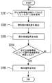
特定部14は、記憶部9に記憶された情報に基づいて除外信号を特定しても良い。かかる場合、例えば、各トレースデータBは、エレベータの故障箇所を示す故障情報と紐付けて記憶部9に記憶される。図9は、この発明の実施の形態2における検索システムの動作例を示すフローチャートである。図9は、特定部14が除外信号を特定するための処理フローを示す。
The identifying
特定部14は、同じ故障情報が紐付けられたトレースデータBを記憶部9から取得する(S201)。例えば、特定部14は、電源回路を示す故障情報が紐付けられた多数のトレースデータBを記憶部9から取得する。
The identifying
特定部14は、同じ故障情報が紐付けられたトレースデータBについて、相互に信号間の類似度を算出する(S202)。即ち、特定部14は、S201で取得したトレースデータBの全ての組み合わせについて、信号間の類似度を算出する。特定部14が信号間の類似度を算出する方法は、例えば第1類似度算出部11が信号間の類似度を算出する方法と同じである。
The identifying
次に、特定部14は、除外候補信号を特定する(S203)。除外信号は、除外候補信号の中から選ばれる。例えば、特定部14は、S202で算出した類似度のばらつきが大きい信号を除外候補信号に特定する。例えば、かご位置は、電源回路の故障との関連性が低い。このため、電源回路を示す故障情報が紐付けられたトレースデータBについて信号間の類似度を算出すると、かご位置を示す信号間の類似度は様々な値を取る。特定部14は、かご位置を示す信号間の類似度のばらつきが閾値を超える場合、かご位置を示す信号を電源回路における除外候補信号に特定する。
Next, the specifying
特定部14は、全ての故障情報における除外候補信号を特定する。このため、特定部14は、1つの故障情報における除外候補信号を特定すると、全ての故障情報について除外候補信号が特定されたか否かを判定する(S204)。除外候補信号が特定されていない故障情報があれば(S204のNo)、その故障情報が紐付けられたトレースデータBが取得され、取得されたトレースデータBに対してS202の処理とS203の処理とが行われる。これにより、全ての故障情報について除外候補信号が特定される。
The identifying
全ての故障情報について除外候補信号が特定されると(S204のYes)、特定部14は、除外信号を特定する(S205)。特定部14は、例えば全ての故障情報について類似度のばらつきが閾値を超える信号を除外信号に特定する。即ち、特定部14は、全ての故障情報における除外候補信号に同じ信号が含まれていれば、その信号を除外信号に特定する。これにより、故障箇所に因らず様々な値を取る信号については、第1類似度算出部11による類似度の算出対象から除外される。
When the exclusion candidate signal is specified for all failure information (Yes in S204), the
上記構成を有する検索システムであれば、トレースデータに含まれる、故障との関連性が極めて低い信号を類似度の算出対象から除外することができる。第2類似度算出部12によって算出された類似度が故障内容との類似性をより強く表すことになるため、故障原因の推定をより容易に行うことができるようになる。
With the search system having the above configuration, it is possible to exclude from the calculation target of the degree of similarity the signal that is included in the trace data and that has a very low relevance to the failure. Since the similarity calculated by the second
実施の形態3.
本実施の形態における検索システムの構成は、実施の形態1或いは2で開示した構成と同じである。本実施の形態では、表示制御部13が表示器15に故障箇所を表示させる例について説明する。本実施の形態では、各トレースデータBは、エレベータの故障箇所を示す故障情報と紐付けて記憶部9に記憶される。本実施の形態における検索システム他の機能は、実施の形態1或いは2で開示した何れかの機能と同じである。
Third Embodiment
The configuration of the search system in the present embodiment is the same as the configuration disclosed in the first or second embodiment. In the present embodiment, an example in which the
図10は、この発明の実施の形態3における検索システムの動作例を示すフローチャートである。図10に示すS301からS304の処理は、図3に示すS101からS104の処理と同じである。 FIG. 10 is a flowchart showing an operation example of the search system in the third embodiment of the present invention. The processes of S301 to S304 shown in FIG. 10 are the same as the processes of S101 to S104 shown in FIG.
トレースデータAと各トレースデータBとの類似度が算出されると(S304のYes)、表示制御部13は、第2類似度算出部12によって算出された類似度とトレースデータBに紐付けられた故障情報とに基づいて、発生している可能性が高い故障箇所を表示器15に表示させる(S305)。
When the similarity between the trace data A and each trace data B is calculated (Yes in S304), the
例えば、表示制御部13は、第2類似度算出部12によって算出された類似度が高い順にトレースデータBを並べ、類似度が高い複数のトレースデータBを抽出する。表示制御部13は、例えば、類似度が高い上位一定数のトレースデータBを抽出する。例えば、表示制御部13は、類似度が高い上位100位までのトレースデータBを抽出する。他の例として、表示制御部13は、類似度が基準値を超えるトレースデータBを抽出しても良い。
For example, the
次に、表示制御部13は、抽出したトレースデータBの故障箇所を特定する。この特定は、例えば、抽出したトレースデータBに紐付けられた故障情報に基づいて行われる。例えば、100個のトレースデータBを抽出した場合、表示制御部13は、この100個のトレースデータBについて故障箇所を特定する。表示制御部13は、抽出した全てのトレースデータBについて故障箇所を特定すると、数が多い順に表示器15に故障箇所を表示させる。
Next, the
図11は、表示器15の表示例を示す図である。例えば、抽出したトレースデータBのうち、故障箇所が制御盤であるデータが50個、故障箇所が電源回路であるデータが30個、故障箇所が巻上機であるデータが15個、及び故障箇所が通信カードであるデータが5個である場合に、図11に示すような表示が行われる。
FIG. 11 is a view showing a display example of the
上記構成を有する検索システムであれば、故障が発生している可能性が高い箇所を故障箇所候補として表示器15に表示させることができる。エレベータの監視員及び保守員は、表示器15に表示された故障箇所候補を優先的に調べるといった適切な対応を取ることができる。
If it is a search system which has the above-mentioned composition, a part with high possibility that failure has occurred can be displayed on
実施の形態1から3では、検索装置1がエレベータ装置に接続される例について説明した。検索装置1が信号群を取得する先は、エレベータ装置に限定されない。検索装置1は、他の設備或いはプラント等から情報群を取得しても良い。
In the first to third embodiments, the example in which the
符号9〜14に示す各部は、検索装置1が有する機能を示す。図12は、検索装置1のハードウェア構成を示す図である。検索装置1は、ハードウェア資源として、例えば入出力インターフェース16とプロセッサ17とメモリ18とを含む回路を備える。記憶部9が有する機能はメモリ18によって実現される。また、検索装置1は、メモリ18に記憶されたプログラムをプロセッサ17によって実行することにより、各部10〜14が有する各機能を実現する。各部10〜14が有する各機能の一部又は全部をハードウェアによって実現しても良い。
Each part shown to numerals 9-14 shows the function which
1 検索装置
2 かご
3 つり合いおもり
4 主ロープ
5 駆動綱車
6 電動機
7 制御盤
8 通信装置
9 記憶部
10 読込部
11 第1類似度算出部
12 第2類似度算出部
13 表示制御部
14 特定部
15 表示器
16 入出力インターフェース
17 プロセッサ
18 メモリ
Claims (5)
複数の信号を含む第2信号群が記憶された記憶手段と、
前記読込手段によって読み込まれた第1信号群に含まれる信号と前記記憶手段に記憶された第2信号群に含まれる信号のうち第1信号群に含まれる当該信号に対応する信号との類似度を、第1信号群に含まれる複数の信号について算出する第1類似度算出手段と、
前記第1類似度算出手段によって算出された複数の類似度に基づいて、前記読込手段によって読み込まれた第1信号群と前記記憶手段に記憶された第2信号群との類似度を算出する第2類似度算出手段と、
前記記憶手段に記憶された第2信号群に含まれる信号の中から除外信号を特定する特定手段と、
を備え、
前記記憶手段に複数の第2信号群が記憶され、
前記第1類似度算出手段は、前記読込手段によって読み込まれた第1信号群と前記記憶手段に記憶された各第2信号群とについて信号間の類似度を算出し、
前記第2類似度算出手段は、前記読込手段によって読み込まれた第1信号群と前記記憶手段に記憶された各第2信号群との類似度を算出し、
第1信号群及び各第2信号群は、エレベータに備えられた複数のセンサからの信号を含み、
各第2信号群は、エレベータの故障箇所を示す故障情報と紐付けて前記記憶手段に記憶され、
前記特定手段は、同じ故障情報が紐付けられた第2信号群について対応する信号間の類似度を算出し、その故障情報について類似度のばらつきが閾値を超える信号を特定し、全ての故障情報について類似度のばらつきが閾値を超える信号を除外信号に特定し、
前記第1類似度算出手段は、前記特定手段によって特定された除外信号については、信号間の類似度を算出しない検索システム。 Reading means for reading a first signal group including a plurality of signals;
Storage means in which a second signal group including a plurality of signals is stored;
Similarity between a signal included in the first signal group read by the reading means and a signal corresponding to the signal included in the first signal group among the signals included in the second signal group stored in the storage means First similarity calculation means for calculating a plurality of signals included in the first signal group;
Calculating a similarity between the first signal group read by the reading unit and the second signal group stored in the storage unit based on the plurality of similarities calculated by the first similarity calculation unit; 2 Similarity calculation means,
Specifying means for specifying an exclusion signal from among the signals contained in the second signal group stored in the storage means;
Equipped with
A plurality of second signal groups are stored in the storage means;
The first similarity calculation means calculates the similarity between signals for the first signal group read by the reading means and each second signal group stored in the storage means,
The second similarity calculation means calculates the similarity between the first signal group read by the reading means and each second signal group stored in the storage means.
The first signal group and the second signal group includes signals from a plurality of sensors provided in the elevators,
Each of the second signal group is stored in the storage means in association with the failure information indicating the failure position of the elevators,
The specifying means calculates the similarity between the corresponding signals for the second signal group to which the same failure information is linked, specifies the signal whose variation in similarity exceeds the threshold for the failure information, and all the failure information Identify the signals whose variation in similarity exceeds the threshold as the exclusion signal,
A search system in which the first similarity calculation means does not calculate the similarity between signals for the excluded signals specified by the specifying means .
前記表示制御部は、前記第2類似度算出手段によって算出された類似度と第2信号群に紐付けられた故障情報とに基づいて、発生している可能性が高い故障箇所を前記表示器に表示させる請求項1に記載の検索システム。 It further comprises a display control unit that controls the display,
The display control unit is configured to display the failure location that is highly likely to be generated based on the similarity calculated by the second similarity calculation unit and the failure information linked to the second signal group. The search system according to claim 1, wherein the search system displays the information.
前記表示制御部は、前記第2類似度算出手段によって算出された類似度順に、第2信号群を示す情報を前記表示器に表示させる請求項1に記載の検索システム。 It further comprises a display control unit that controls the display,
The search system according to claim 1, wherein the display control unit causes the display to display information indicating a second signal group in the order of the degree of similarity calculated by the second degree of similarity calculation unit.
前記第1類似度算出手段は、類似度の最大値が信号長に因らず同じ値になるように信号間の類似度を算出する請求項1から請求項3の何れか一項に記載の検索システム。 The first signal group and each second signal group include a plurality of signals having different signal lengths,
The said 1st similarity degree calculation means is described in any one of Claim 1 to 3 which calculates the similarity degree between signals so that the maximum value of a similarity degree may become the same value irrespective of a signal length. Search system.
前記第1類似度算出手段は、重要度が同じ信号については、類似度の最大値が信号長に因らず同じ値になるように信号間の類似度を算出する請求項1から請求項3の何れか一項に記載の検索システム。 The first signal group and each second signal group include a plurality of signals of different importance and signal length,
The first similarity calculation means calculates the similarity between the signals so that the maximum value of the similarity becomes the same value regardless of the signal length for the signals having the same importance. The search system according to any one of the above.
Priority Applications (5)
| Application Number | Priority Date | Filing Date | Title |
|---|---|---|---|
| JP2015154968A JP6520539B2 (en) | 2015-08-05 | 2015-08-05 | Search system |
| KR1020187005750A KR102045161B1 (en) | 2015-08-05 | 2016-08-02 | Search system |
| DE112016003529.2T DE112016003529T8 (en) | 2015-08-05 | 2016-08-02 | search system |
| PCT/JP2016/072632 WO2017022752A1 (en) | 2015-08-05 | 2016-08-02 | Search system |
| CN201680043947.8A CN107851126A (en) | 2015-08-05 | 2016-08-02 | searching system |
Applications Claiming Priority (1)
| Application Number | Priority Date | Filing Date | Title |
|---|---|---|---|
| JP2015154968A JP6520539B2 (en) | 2015-08-05 | 2015-08-05 | Search system |
Publications (3)
| Publication Number | Publication Date |
|---|---|
| JP2017033437A JP2017033437A (en) | 2017-02-09 |
| JP2017033437A5 JP2017033437A5 (en) | 2017-09-21 |
| JP6520539B2 true JP6520539B2 (en) | 2019-05-29 |
Family
ID=57943023
Family Applications (1)
| Application Number | Title | Priority Date | Filing Date |
|---|---|---|---|
| JP2015154968A Active JP6520539B2 (en) | 2015-08-05 | 2015-08-05 | Search system |
Country Status (5)
| Country | Link |
|---|---|
| JP (1) | JP6520539B2 (en) |
| KR (1) | KR102045161B1 (en) |
| CN (1) | CN107851126A (en) |
| DE (1) | DE112016003529T8 (en) |
| WO (1) | WO2017022752A1 (en) |
Families Citing this family (4)
| Publication number | Priority date | Publication date | Assignee | Title |
|---|---|---|---|---|
| KR102377658B1 (en) | 2016-03-23 | 2022-03-24 | 엔지케이 인슐레이터 엘티디 | Cordierite sintered body and production thereof and composite substrate |
| KR101971553B1 (en) * | 2017-03-21 | 2019-04-23 | (주)심플랫폼 | Device management system and method based on Internet Of Things |
| CN111492371B (en) * | 2017-12-14 | 2023-05-26 | 三菱电机株式会社 | Search system and monitoring system |
| JP6766982B2 (en) * | 2018-05-31 | 2020-10-14 | 三菱電機ビルテクノサービス株式会社 | Elevator maintenance work support device |
Family Cites Families (11)
| Publication number | Priority date | Publication date | Assignee | Title |
|---|---|---|---|---|
| JPS6029833B2 (en) | 1976-06-28 | 1985-07-12 | 株式会社日立製作所 | Totally hermetic electric compressor |
| CN1036260C (en) * | 1992-01-29 | 1997-10-29 | 天津大学 | Signal acquisition and display apparatus for elevator |
| JPH07228443A (en) * | 1994-02-15 | 1995-08-29 | Hitachi Building Syst Eng & Service Co Ltd | Inspecting device for elevator |
| US7575103B2 (en) * | 2004-08-11 | 2009-08-18 | Mitsubishi Denki Kabushiki Kaisha | Elevator supervisory system for managing operating condition data |
| WO2010041744A1 (en) * | 2008-10-09 | 2010-04-15 | 国立大学法人 北海道大学 | Moving picture browsing system, and moving picture browsing program |
| CN101597000B (en) * | 2009-06-23 | 2011-03-30 | 福建省特种设备监督检验所 | Intelligent detection method and intelligent detection system for operating test of elevator |
| EP2336070B1 (en) * | 2009-12-18 | 2016-08-03 | ThyssenKrupp Aufzugswerke GmbH | Method for remote diagnosis of a lift assembly and lift assembly for executing the method |
| CN102765643B (en) * | 2012-05-31 | 2015-06-17 | 天津大学 | Elevator fault diagnosis and early-warning method based on data drive |
| JP5820072B2 (en) * | 2012-07-11 | 2015-11-24 | 株式会社日立製作所 | Similar failure case search device |
| JP6103899B2 (en) * | 2012-11-28 | 2017-03-29 | 三菱電機株式会社 | Failure location estimation device |
| JP6082341B2 (en) * | 2013-12-05 | 2017-02-15 | 株式会社日立ソリューションズ | Abnormality detection apparatus and abnormality detection method |
-
2015
- 2015-08-05 JP JP2015154968A patent/JP6520539B2/en active Active
-
2016
- 2016-08-02 KR KR1020187005750A patent/KR102045161B1/en active IP Right Grant
- 2016-08-02 WO PCT/JP2016/072632 patent/WO2017022752A1/en active Application Filing
- 2016-08-02 CN CN201680043947.8A patent/CN107851126A/en active Pending
- 2016-08-02 DE DE112016003529.2T patent/DE112016003529T8/en active Active
Also Published As
| Publication number | Publication date |
|---|---|
| DE112016003529T5 (en) | 2018-04-26 |
| WO2017022752A1 (en) | 2017-02-09 |
| DE112016003529T8 (en) | 2018-06-14 |
| KR102045161B1 (en) | 2019-11-14 |
| JP2017033437A (en) | 2017-02-09 |
| CN107851126A (en) | 2018-03-27 |
| KR20180035854A (en) | 2018-04-06 |
Similar Documents
| Publication | Publication Date | Title |
|---|---|---|
| JP6520539B2 (en) | Search system | |
| CN110790105B (en) | Elevator door system diagnosis and decline time prediction method and diagnosis and prediction system | |
| US20200102188A1 (en) | Elevator system component analysis | |
| US10915419B2 (en) | Industrial control system, and assistance apparatus, control assist method, and program thereof | |
| US11591183B2 (en) | Enhancing elevator sensor operation for improved maintenance | |
| CN102826452A (en) | Crane load spectrum data acquisition system, method thereof, and fatigue life assessment system | |
| EP3617117B1 (en) | Model development framework for remote monitoring condition-based maintenance | |
| JP6711418B2 (en) | Recovery support system | |
| US11669771B2 (en) | Learning system, analysis system, learning method, and storage medium | |
| US10460431B2 (en) | Part recognition and damage characterization using deep learning | |
| JP6808588B2 (en) | Elevator system | |
| CN205332998U (en) | A health monitoring system for building structure | |
| CN112203965B (en) | Maintenance work auxiliary device for elevator | |
| CN110520806A (en) | Identification to the deviation engineering modification of programmable logic controller (PLC) | |
| CN108124442B (en) | Elevator element parameter calibration method, device, equipment and storage medium | |
| US11907053B2 (en) | Failure handling apparatus and system, rule list generation method, and non-transitory computer-readable medium | |
| CN107489454A (en) | The manned monitoring method of conveying arrangement and device | |
| CN110382389B (en) | Recovery support system | |
| CN109229097B (en) | Cruise control method and device | |
| CN111492371B (en) | Search system and monitoring system | |
| JP6693576B2 (en) | Recovery system | |
| JP6575694B2 (en) | Search system | |
| CN113177077B (en) | Abnormal event determination method and device for automatic driving and electronic equipment | |
| CN117235514A (en) | Elevator fault diagnosis system using cyclic neural network model | |
| JP5142932B2 (en) | Monitoring screen display device |
Legal Events
| Date | Code | Title | Description |
|---|---|---|---|
| A521 | Request for written amendment filed |
Free format text: JAPANESE INTERMEDIATE CODE: A523 Effective date: 20170807 |
|
| A621 | Written request for application examination |
Free format text: JAPANESE INTERMEDIATE CODE: A621 Effective date: 20170807 |
|
| A131 | Notification of reasons for refusal |
Free format text: JAPANESE INTERMEDIATE CODE: A131 Effective date: 20181023 |
|
| A521 | Request for written amendment filed |
Free format text: JAPANESE INTERMEDIATE CODE: A523 Effective date: 20181211 |
|
| TRDD | Decision of grant or rejection written | ||
| A01 | Written decision to grant a patent or to grant a registration (utility model) |
Free format text: JAPANESE INTERMEDIATE CODE: A01 Effective date: 20190402 |
|
| A61 | First payment of annual fees (during grant procedure) |
Free format text: JAPANESE INTERMEDIATE CODE: A61 Effective date: 20190415 |
|
| R150 | Certificate of patent or registration of utility model |
Ref document number: 6520539 Country of ref document: JP Free format text: JAPANESE INTERMEDIATE CODE: R150 |
|
| R250 | Receipt of annual fees |
Free format text: JAPANESE INTERMEDIATE CODE: R250 |
|
| S533 | Written request for registration of change of name |
Free format text: JAPANESE INTERMEDIATE CODE: R313533 |
|
| R350 | Written notification of registration of transfer |
Free format text: JAPANESE INTERMEDIATE CODE: R350 |
|
| R250 | Receipt of annual fees |
Free format text: JAPANESE INTERMEDIATE CODE: R250 |