JP6501143B2 - Drive transmission device and image forming apparatus - Google Patents
Drive transmission device and image forming apparatus Download PDFInfo
- Publication number
- JP6501143B2 JP6501143B2 JP2015023306A JP2015023306A JP6501143B2 JP 6501143 B2 JP6501143 B2 JP 6501143B2 JP 2015023306 A JP2015023306 A JP 2015023306A JP 2015023306 A JP2015023306 A JP 2015023306A JP 6501143 B2 JP6501143 B2 JP 6501143B2
- Authority
- JP
- Japan
- Prior art keywords
- drive
- drive transmission
- belt
- gear
- developing
- Prior art date
- Legal status (The legal status is an assumption and is not a legal conclusion. Google has not performed a legal analysis and makes no representation as to the accuracy of the status listed.)
- Active
Links
Images


Classifications
-
- F—MECHANICAL ENGINEERING; LIGHTING; HEATING; WEAPONS; BLASTING
- F16—ENGINEERING ELEMENTS AND UNITS; GENERAL MEASURES FOR PRODUCING AND MAINTAINING EFFECTIVE FUNCTIONING OF MACHINES OR INSTALLATIONS; THERMAL INSULATION IN GENERAL
- F16H—GEARING
- F16H57/00—General details of gearing
- F16H57/04—Features relating to lubrication or cooling or heating
- F16H57/0463—Grease lubrication; Drop-feed lubrication
- F16H57/0464—Grease lubrication
-
- G—PHYSICS
- G03—PHOTOGRAPHY; CINEMATOGRAPHY; ANALOGOUS TECHNIQUES USING WAVES OTHER THAN OPTICAL WAVES; ELECTROGRAPHY; HOLOGRAPHY
- G03G—ELECTROGRAPHY; ELECTROPHOTOGRAPHY; MAGNETOGRAPHY
- G03G21/00—Arrangements not provided for by groups G03G13/00 - G03G19/00, e.g. cleaning, elimination of residual charge
- G03G21/16—Mechanical means for facilitating the maintenance of the apparatus, e.g. modular arrangements
- G03G21/1642—Mechanical means for facilitating the maintenance of the apparatus, e.g. modular arrangements for connecting the different parts of the apparatus
- G03G21/1647—Mechanical connection means
-
- G—PHYSICS
- G03—PHOTOGRAPHY; CINEMATOGRAPHY; ANALOGOUS TECHNIQUES USING WAVES OTHER THAN OPTICAL WAVES; ELECTROGRAPHY; HOLOGRAPHY
- G03G—ELECTROGRAPHY; ELECTROPHOTOGRAPHY; MAGNETOGRAPHY
- G03G21/00—Arrangements not provided for by groups G03G13/00 - G03G19/00, e.g. cleaning, elimination of residual charge
- G03G21/16—Mechanical means for facilitating the maintenance of the apparatus, e.g. modular arrangements
- G03G21/18—Mechanical means for facilitating the maintenance of the apparatus, e.g. modular arrangements using a processing cartridge, whereby the process cartridge comprises at least two image processing means in a single unit
- G03G21/1839—Means for handling the process cartridge in the apparatus body
- G03G21/1857—Means for handling the process cartridge in the apparatus body for transmitting mechanical drive power to the process cartridge, drive mechanisms, gears, couplings, braking mechanisms
Description
本発明は、駆動伝達装置および画像形成装置に関するものである。 The present invention relates to a drive transmission device and an image forming apparatus.
複写機、プリンタ、ファクシミリ、またはそれらの複合機における画像形成装置においては、画像形成動作のために多くの駆動手段が備えられており、感光体や転写ベルトの動作などに用いられている。 In an image forming apparatus in a copying machine, a printer, a facsimile machine, or a complex machine thereof, many driving means are provided for an image forming operation, and are used for an operation of a photosensitive member or a transfer belt.
特許文献1には、駆動モータの駆動力を、第1回転体へ伝達する第1駆動伝達部と、第2回転体へ伝達する第2駆動伝達部とを備えた駆動装置が記載されている。第1駆動伝達部には、駆動プーリと従動プーリとに張架された駆動ベルトを備えており、第2駆動伝達部は、複数の外歯車で構成されている。
外歯車の歯にグリスを塗布し、歯にグリスが塗布された外歯車を駆動装置にセットして検証実験を行った。その結果、外歯車の歯にグリスを塗ることにより、回転精度が向上し、騒音を低減することができた。しかし、この検証実験において、駆動装置を起動させた際に、塗布したグリスが、外歯車の回転による遠心力で飛び散り、飛び散ったグリスが駆動ベルトに付着するという課題が新たに発生することが判明した。この課題は、例えば、メンテナンス時に外歯車にグリスを塗布し、メンテナンス後の起動時に起こりうる。また、工場出荷時の駆動検査工程など、グリスが塗布された外歯車が初めて回転駆動する際にも起こりうる。 Grease was applied to the teeth of the external gear, and the external gear with the grease applied to the teeth was set in the drive device to conduct a verification experiment. As a result, by applying grease to the external gear teeth, the rotational accuracy was improved and the noise could be reduced. However, in this verification experiment, it has been found that, when the drive device is activated, the applied grease spatters due to the centrifugal force due to the rotation of the external gear, and the problem of spattered grease adhering to the driving belt newly occurs. did. This problem may occur, for example, at the time of start after maintenance by applying grease to the external gear at the time of maintenance. In addition, this may occur also when the external gear with grease applied is driven to rotate for the first time, such as a drive inspection process at the time of factory shipment.
グリスが駆動ベルトに付着すると、次のような不具合を引き起こすおそれがある。すなわち、ゴム製の駆動ベルトがグリスにより劣化し、早期に寿命を迎えるおそれがあるという不具合である。また、各プーリと駆動ベルトとの摩擦力で駆動伝達を行う装置においては、グリスが駆動ベルトの裏面(プーリと当接する側)に付着すると、各プーリと駆動ベルトとの摩擦力が低下し、適切な駆動が行えないという不具合も生じるおそれがある。 If grease adheres to the drive belt, the following problems may occur. That is, the rubber drive belt is deteriorated by grease and there is a possibility that the life of the drive belt may reach an early stage. Further, in the device that transmits the drive by the frictional force between each pulley and the drive belt, when the grease adheres to the back surface of the drive belt (the side contacting the pulley), the frictional force between each pulley and the drive belt decreases. There is also a possibility that a problem that appropriate driving can not be performed may occur.
本発明は以上の課題に鑑みなされたものであり、その目的は、歯にグリスが塗布されていない場合に比べて回転精度を向上でき、かつ、騒音を抑制するとともに、駆動ベルトへのグリスの付着を抑制することができる駆動伝達装置および画像形成装置を提供することである。 The present invention has been made in view of the above problems, and its object is to improve the rotational accuracy as compared with the case where no grease is applied to the teeth, and to suppress the noise, as well as to apply grease to the drive belt. An object of the present invention is to provide a drive transmission device and an image forming apparatus capable of suppressing adhesion.
上記目的を達成するために、請求項1の発明は、外歯部を備えた出力軸を有する第1駆動源と、前記外歯部と直接噛み合う内歯部及び該内歯部と同軸上に配置された外歯部とを備え、現像ローラに駆動的に連結された第1駆動伝達部材と、前記現像ローラとは別の駆動回転体に駆動力を伝達する第2駆動伝達部材と、前記第2駆動伝達部材と駆動的に連結された第1プーリと、第2プーリとに張架された駆動ベルトとを備えた駆動伝達装置において、前記第1駆動伝達部材の内歯部にグリスが塗布されるとともに、前記駆動ベルトは、前記第1駆動伝達部材の内歯部に隣接して配置されており、前記第1駆動伝達部材は、前記内歯部の回転軸方向一方の端部が塞がれており、回転軸方向他方の端部が開放されるとともに、前記内歯部の歯を前記第1駆動伝達部材の回転に伴い塞がれた側へスラスト力が働くはす歯としたことを特徴とするものである。
In order to achieve the above object, according to the invention of
本発明によれば、回転精度を向上させ、かつ、騒音を抑制するとともに、駆動ベルトへのグリスの付着を抑制することができる。 According to the present invention, it is possible to improve the rotation accuracy, suppress noise, and suppress adhesion of grease to the drive belt.
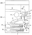
図1は本発明の一実施形態に係る画像形成装置の概略を示す図である。
画像形成装置たる複写機の装置本体100の上部には、画像読取装置200が取り付けられている。
FIG. 1 is a schematic view of an image forming apparatus according to an embodiment of the present invention.
An
装置本体100の内部には、プロセスカートリッジ1が設けられている。
図2(a)は、プロセスカートリッジの斜視図であり、図2(b)は、プロセスカートリッジの断面図である。
図2(b)に示すように、プロセスカートリッジ1は、潜像担持体たる感光体10と、感光体10の周囲に配置され、感光体10に作用するプロセス手段としての帯電装置11、現像装置12およびクリーニング装置14などを備えている。プロセスカートリッジ1は、装置本体100に着脱可能に装着されている。感光体10、帯電装置11、現像装置12及びクリーニング装置14がプロセスカートリッジ1としてユニット化されることにより、交換やメンテナンスの作業が容易になる。また、各部材間の位置精度を高精度の維持することができ、形成される画像品質の向上を図ることができる。
A
2 (a) is a perspective view of the process cartridge, and FIG. 2 (b) is a cross-sectional view of the process cartridge.
As shown in FIG. 2B, the
帯電手段たる帯電装置11は、帯電バイアスを印加され、感光体10表面に電荷を与えて感光体10を一様帯電する帯電ローラ11aと、帯電ローラ11aの表面に付着したトナーなどの付着物を除去する除去ローラ11bとを備えている。
The charging device 11, which is a charging unit, receives a charging bias, applies charge to the surface of the
現像手段たる現像装置12は、現像剤搬送手段としての第1搬送スクリュウ12bが配設された第1剤収容室V1を有している。また、現像剤搬送手段としての第2搬送スクリュウ12c、現像剤担持体としての現像ローラ12a、現像剤規制部材としてのドクターブレード12dなどが配設された第2剤収容室V2も有している。
The developing
これら2つの剤収容室V1,V2内には、磁性キャリアとマイナス帯電性のトナーとからなる二成分現像剤である現像剤が内包されている。第1搬送スクリュウ12bは、駆動手段によって回転駆動することで、第1剤収容室V1内の現像剤を図中の手前側へ搬送する。そして、第1搬送スクリュウ12bにより第1剤収容室V1の図中手前側端部まで搬送された現像剤は、第2剤収容室V2に進入する。
In these two agent storage chambers V1 and V2, a developer which is a two-component developer composed of a magnetic carrier and a toner having a negative chargeability is contained. The first transport screw 12 b is rotationally driven by the drive unit to transport the developer in the first agent
第2剤収容室V2内の第2搬送スクリュウ12cは、駆動手段によって回転駆動することで、現像剤を図中の奥側へ搬送する。このようにして現像剤を搬送する第2搬送スクリュウ12cの上方には、現像ローラ12aが第2搬送スクリュウ12cと平行な姿勢で配設されている。この現像ローラ12aは、回転駆動する非磁性スリーブからなる現像スリーブ内に固定配置されたマグネットローラを内包した構成となっている。
The
第2搬送スクリュウ12cによって搬送される現像剤の一部は、現像ローラ12a内のマグネットローラの発する磁力によって現像ローラ12aの表面に汲み上げられる。そして、現像ローラ12aの表面と所定の間隙を保持するように配設されたドクターブレード12dによってその層厚が規制された後、感光体10と対向する現像領域まで搬送され、感光体10上の静電潜像にトナーを付着させる。この付着により、感光体10上にトナー像が形成される。現像によってトナーを消費した現像剤は、現像ローラ12aの表面移動に伴って第2搬送スクリュウ12c上に戻される。そして、第2搬送スクリュウ12cにより第2剤収容室V2の端部まで搬送された現像剤は、第1剤収容室V1内に戻る。このようにして、現像剤は現像装置内を循環搬送される。
A part of the developer conveyed by the
また、現像装置12は、第1剤収容室V1の現像剤のトナー濃度を検知するトナー濃度センサを有している。トナー濃度センサは、現像剤の透磁率から現像剤のトナー濃度を測定するもので、トナー濃度が低くなると磁性体のキャリアが密集してくるので透磁率は高くなる。このトナー濃度センサ124によって測定された値が、狙いの値(閾値)を超える場合は図1に示すトナーボトル20からトナー補給され、トナー濃度を一定濃度に制御する。狙いの値は、感光体10に形成されたトナーパターンのトナー付着量を光学センサで検知し、その検知結果に基づいて決められる。
Further, the developing
このような動作によって、感光体上の基準パターン濃度を一定に保つように制御しているが、トナーボトル20のトナーがなくなった場合は、濃度低下を抑制できなくなる。このような状況においては、所定期間、トナーボトル20からトナーを補給する動作をしたにも係わらず、光学センサによるトナーパターンの検知結果が改善されない。従って、トナーボトル20からトナーを補給する動作をしたにも係わらず、光学センサによるトナーパターンの検知結果が改善されなかった場合は、トナーがなくなった(トナーエンド)と、制御手段で判断(あるいは推定判断)する。
By such an operation, control is performed so as to keep the reference pattern density on the photosensitive member constant, but when the toner of the
また、トナーエンドと判断した後、トナーボトル20を交換し、交換したトナーボトル20内のトナーを現像装置12へ供給するトナーエンドのリカバリのときは、以下のような動作を行う。すなわち、補給されたトナーと現像剤を良好に混合させるために、現像ローラ12aや各搬送スクリュウ12b,12cを回転させる。また、このとき、現像ローラ12a上の現像剤に不均一な摺動が生じるのを防ぐために、感光体10も回転させるよう、駆動を付与する。
Further, after the toner end is determined, the
クリーニング手段たるクリーニング装置14は、感光体10表面に当接して感光体10に付着している転写残トナーを掻き取るクリーニングブレード14aを備えている。また、回収部Wに収容され、クリーニングブレード14aにより回収された回収トナーを搬送するトナー回収コイル14bを備えている。トナー回収コイル14bにより搬送された回収トナーは、トナー搬送装置により、現像装置12または廃トナーボトル41へ搬送される。
The cleaning device 14 serving as the cleaning means includes a
図1に示す転写手段たる転写装置17は、転写ローラ16を備えており、転写ローラ16は、感光体10の周面に押圧されて当接されている。また、転写装置17の上方には、定着手段たる熱定着装置24が設けられている。熱定着装置24は、加熱ローラ25と加圧ローラ26を有する。また、装置本体100には、潜像形成手段たるレーザ書込装置21が備えられている。レーザ書込装置21には、レーザ光源、走査用の回転多面鏡、ポリゴンモータ、fθレンズなどを備えている。また、装置本体は、転写紙、OHPフィルムなどのシートSを収納するシートカセット22が多段に備えられている。
A
以上のような構成の装置を用いてコピーするとき、ユーザーがスタートスイッチを押す。すると、まず、画像読取装置200にセットされた原稿内容を読み取る。また、このとき同時に、感光体駆動モータで感光体10を回転し、帯電ローラ11aを用いた帯電装置11で感光体10の表面を一様に帯電する。次いで画像読取装置200によって読み取った原稿内容に応じてレーザ光を照射してレーザ書込装置21を用いて書き込み工程を実行する。そして、感光体10の表面に静電潜像を形成した後、現像装置12を用いてトナーを付着させて静電潜像を可視像化(現像)する。
When copying using the apparatus configured as described above, the user presses the start switch. Then, first, the document content set in the
また、スタートスイッチをユーザーが押すと同時に、多段のシートカセット22から選択されたシートSを呼出ローラ27により送り出す。次いで、供給ローラ28と分離ローラ29で1枚ずつ分離して供給路R1に送る。供給路R1に送られたシートSは、シート搬送ローラ30で搬送されて、レジストローラ23に突き当てて止められる。そして、感光体10の可視像化したトナー画像と回転タイミングを合わせて、転写ローラ16が感光体10と当接して形成された転写ニップへと送り込まれる。
At the same time as the user presses the start switch, the sheet S selected from the
転写ニップへと送り込まれたシートSは、転写装置17により感光体10上のトナー画像を転写される。画像転写後の感光体10上の残留トナーはクリーニング装置14で除去・清掃され、残留トナーを除去された感光体10上の残留電位は、除電装置で除去される。そして、帯電装置11から始まる次の画像形成に備える。
The sheet S fed to the transfer nip has the toner image on the
一方、画像転写された後のシートSは、熱定着装置24に導かれ、加熱ローラ25と加圧ローラ26の間に通されて、これらローラに搬送されながら、熱と圧力を加えられてトナー画像を定着される。画像定着されたシートSは、その後、排紙ローラ31により排紙スタック部32上に排出されてスタックされる。
On the other hand, the sheet S after image transfer is guided to the
次に、本実施形態の特徴点について説明する。
図3は、感光体10、現像ローラなどを駆動する駆動装置50の斜視図であり、図4は、駆動装置50の内部を示す斜視図であり、図5は、駆動装置50の概略断面図である。
駆動装置50は、感光体モータ51や、現像モータ52およびこれらモータの駆動力を伝達するためのギヤなどの駆動伝達部材を保持する保持部60を備えている。
保持部60は、樹脂ハウジング61と、第一部材たる金属製のブラケット62と、第二部材たる金属製の制振板63とを備えている。
Next, features of the present embodiment will be described.
FIG. 3 is a perspective view of the driving
The driving
The holding
図4、図5に示すように、樹脂ハウジング61内には、感光体ギヤ53、現像内歯車55、現像従動ギヤ56および現像アイドラギヤ57を収納している。また、廃トナーボトル内に落下してきた廃トナーを、廃トナーボトル41の奥側へ搬送するための廃トナー搬送スクリュウに駆動伝達するための部材も収納している。具体的には、搬送用駆動ギヤ71、搬送用駆動プーリ72、搬送用タイミングベルト73、搬送用従動プーリ74、搬送用アイドラギヤ75を収納している。
As shown in FIGS. 4 and 5, the
感光体ギヤ53は、保持部60に回転自在に支持された金属製の感光体駆動軸53aに固定されており、感光体モータ51のモータギヤ51aに噛み合っている。感光体駆動軸53aの一端は、ブラケット62および制振板63を貫通して、ブラケット62に回転自在の支持されており、他端には、感光体駆動側カップリング54が取り付けられており、樹脂ハウジング61に回転自在に支持されている。感光体駆動側カップリング54には、感光体10の回転軸の端部に固定された感光体従動側カップリングが連結されている。
The
現像内歯車55は、樹脂ハウジング61に固定された金属製の現像駆動ピン55aに回転自在に支持され、現像モータ52のモータギヤ52aに噛み合っている。現像内歯車55と現像内歯車55と同軸上に配置された現像従動ギヤ56とは樹脂の一体成型品であり、現像従動ギヤ56には、現像アイドラギヤ57が噛み合っている。現像駆動ピン55aの先端は、ブラケット62に嵌合し、先端がブラケット62に位置決めされている。
The development
現像アイドラギヤ57の軸中心には、現像駆動側カップリング58が設けられており、現像駆動側カップリング58は、樹脂ハウジング61を貫通し、かつ、回転自在に樹脂ハウジング61に支持されている。現像駆動側カップリング58には、現像ローラ12aの回転軸の端部に固定された現像従動側カップリングが連結されている。現像アイドラギヤ57と現像駆動側カップリング58は、樹脂の一体成型品である。
A
また、感光体モータ51のモータギヤ51aには、搬送用駆動ギヤ71も噛み合っている。樹脂の一体成型により搬送用駆動ギヤ71と一体成形される搬送用駆動プーリ72と、樹脂の一体成型により搬送用アイドラギヤ75と一体成形される搬送用従動プーリ74とに駆動ベルトたる搬送用タイミングベルト73が張架されている。また、搬送用タイミングベルト73に替えて、搬送用Vベルトとし、各プーリとの摩擦力により駆動力を伝達してもよい。
Further, the
搬送用駆動ギヤ71と搬送用駆動プーリ72とを有する樹脂の一体成型品は、一端が樹脂ハウジング61に固定された金属製の搬送駆動ピン72aに回転自在に支持されている。搬送駆動ピン72aの先端は、ブラケット62に嵌合し、先端がブラケット62に位置決めされている。また、搬送用アイドラギヤ75と搬送用従動プーリ74とを有する樹脂の一体成型品は、樹脂ハウジング61に固定された金属製の搬送従動ピン74aに回転自在に支持されている。搬送従動ピン74aの先端は、ブラケット62に嵌合し、先端がブラケット62に位置決めされている。
An integrally molded product of resin having the
搬送用アイドラギヤ75の一部は、図4に示すように、樹脂ハウジング61の側面開口部61aから露出している。この側面開口部61aから、図5に示すように、廃トナー搬送スクリュウのスクリュウ軸77aの一端に固定されたスクリュウ駆動ギヤ76が搬送用アイドラギヤ75に噛み合っている。
As shown in FIG. 4, a portion of the transfer
図3に示すように、ブラケット62には、アースに接続されたアース板65の一端がネジ83によりネジ止めされている。また、ブラケット62から貫通した感光体駆動軸53aの一端には、アース電極板64の一端が固定されており、アース電極板64の他端は、ネジ82によりブラケット62にネジ止めされている。これにより、感光体10は、感光体駆動軸53a、アース電極板64、ブラケット62、アース板65を介して接地される。
As shown in FIG. 3, one end of a
図6は、駆動装置50のモータ側正面図である。
図6に示すように、制振板63とブラケット62とは、お互い重ね合わされており、制振板63の縁5箇所が、ネジ81a〜81eによってブラケット62を介して樹脂ハウジング61に固定されている。これにより、ブラケット62と制振板63とが、制振板63の縁5箇所81a〜81eで、部分的に結合された状態となる。また、感光体モータ51と現像モータ52とは、制振板63を挟んで、ブラケット62にネジ止めされている。
FIG. 6 is a front view of the
As shown in FIG. 6, the damping
駆動装置50の保持部60は、振動部材として、感光体ギヤ53や現像内歯車55などの複数の駆動伝達部材、感光体モータ51および現像モータ52などを保持している。これら振動部材の振動によって、騒音が発生するおそれがある。感光体モータ51および現像モータ52の振動は、これらに接触する制振板63に伝播し、制振板63が感光体モータ51および現像モータ52の振動により振動する。一方、感光体ギヤ53や現像内歯車55などの複数の駆動伝達部材で発生した振動は、ブラケット62に当接する感光体駆動軸53a、現像駆動ピン55a、搬送駆動ピン72aおよび搬送従動ピン74aなどを介してブラケット62に伝播する。これにより、ブラケット62が振動する。
The holding
ブラケット62と制振板63とは、重ねあわせられ、先の図6に示すように、制振板63の縁5箇所81a〜81eで、部分的に結合されている。そのため、制振板63とブラケット62とは一体となって振動せず、それぞれ個別に振動する。具体的には、制振板63は、感光体モータ51および現像モータ52の振動で振動し、ブラケット62は、樹脂ハウジング61に収納されているギヤなどの各種駆動伝達部材の振動により振動するのである。そして、制振板63とブラケット62の振動が制振板63とブラケット62との部分的結合箇所(制振板63の縁5箇所81a〜81e)で、互いの振動が干渉する。このとき、上記結合箇所で制振板63の振動とブラケット62の振動とが互いに打ち消し合う位相差が生じるよう、制振板63やブラケット62の形状や、剛性などにすることで、制振板63とブラケット62との振動が低減される。
The
保持部60の各歯車の歯にグリスを塗布することにより、歯面同士の摩擦が低減され、振動を抑制でき、回転精度を向上できたり、騒音を抑制できたりして好ましい。しかしながら、先の図4に示すように現像モータ52のモータギヤ52aと噛み合う歯車は、駆動ベルトたるタイミングベルト73に近接配置されている。また、図5に示すように、現像モータ52のモータギヤ52aと噛み合う歯車は、搬送用タイミングベルト73のベルト面に対向配置されている。そのため、現像モータ52のモータギヤ52aと噛み合う歯車を外歯車とし、この外歯車の歯にグリスを塗った場合、外歯車の回転による遠心力で、歯に塗布したグリスが飛び散り、搬送用タイミングベルト73に付着してしまう。搬送用タイミングベルト73は、ゴム製であり、グリスが付着すると、付着した箇所が劣化し、早期に寿命を迎えるという不具合が発生するおそれがある。
By applying grease to the teeth of each gear of the holding
また、搬送用駆動プーリ72と、搬送用従動プーリ74に張架する駆動ベルトを、搬送用Vベルトとし、各プーリとの摩擦力により駆動力を伝達を行うようにした場合、飛び散ったグリスがベルト裏面に付着すると、次の不具合が発生する。すなわち、各プーリと搬送用Vベルトとの摩擦力が低下し、安定した駆動伝達ができなくなるという不具合である。
In addition, when the drive belt stretched between the
また、グリスの飛び散りを抑えるために歯の一枚、一枚に刷け塗りで薄くグリスを塗布することも考えられるが、作業が大変であり、製造コストが嵩んでしまうという不具合がある。 In addition, it is conceivable to apply a thin coat of grease by printing on one sheet or one sheet of teeth in order to suppress the spatter of grease, but the operation is difficult and the manufacturing cost is increased.
このため、本実施形態では、現像モータ52のモータギヤ52aと噛み合う歯車を、現像内歯車55とした。これにより、現像内歯車55に塗布されたグリスに遠心力が作用しても、飛び散ることがない。その結果、搬送用タイミングベルト73などの駆動ベルトにグリスが付着するのを抑制することができる。また、点塗り等の簡単な塗布作業でグリスを内歯車に塗布することができ、製造コストの上昇を抑制することができる。
For this reason, in the present embodiment, the gear engaged with the
また、現像モータ52のモータギヤ52aと噛み合う歯車を、現像内歯車55とすることにより、モータギヤ52aとの噛み合い率を高めることができ、回転ムラや騒音・振動の発生を抑制することができる。
Further, by using a gear for meshing with the
また、現像内歯車55は、はす歯とし、はす歯の向きを、現像ローラ12a回転駆動時に生じるスラスト力の向きが、現像ローラ方向となるような向きとする。具体的には、はす歯の回転方向の傾斜を、現像モータ側が、現像ローラ側よりも回転方向上流側となるようにするのである。
スラスト力が現像モータ側へ働く場合は、現像モータ52のモータギヤ52aと現像内歯車55との噛み合いで発生したスラスト力で、グリスが現像内歯車の開口端面まで移動するおそれがある。開口端面まで移動してきたグリスは、遠心力により開口部の縁をラジアル方向に移動し、最終的には飛び散るおそれがある。一方、スラスト力が現像ローラ側へ働く場合は、現像モータ52のモータギヤ52aと現像内歯車55との噛み合いで発生したスラスト力で、グリスが現像ローラ側へ移動する。グリスが現像ローラ側へ移動しても、図5に示すように、現像内歯車55の現像ローラ側は塞がれている。そのため、スラスト力で移動してきたグリスが飛散するのを防止することができる。
Further, the developing
When the thrust force acts on the developing motor side, there is a possibility that the grease may move to the open end face of the developing internal gear by the thrust force generated by the engagement of the
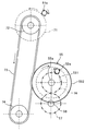
次に、駆動装置50の変形例について説明する。
図7は、駆動装置50の変形例の特徴的な部分について、示す概略構成図である。
図7に示すように、この変形例においては、現像内歯車55の外周面552を、搬送用タイミングベルト73のおもて面に当接させ、現像内歯車55を搬送用タイミングベルト73にテンションを付与するタイトナとして用いるようにしたものである。なお、図中符号551は、現像内歯車55の内歯である。
Next, a modification of the
FIG. 7 is a schematic configuration view showing characteristic parts of the modified example of the
As shown in FIG. 7, in this modification, the outer
現像内歯車55を、タイトナとして用いることにより、現像内歯車55とは別にタイトナを設ける場合に比べて、部品点数を削減することができ、装置を安価にすることができる。また、現像内歯車55により搬送用タイミングベルト73にテンションを付与することにより、各プーリと搬送用タイミングベルト73との噛み合いが良好になり、良好な駆動伝達を行うことができる。
By using the developing
また、現像内歯車55は、搬送用タイミングベルト73の二つの張架領域のうち、駆動伝達側ではない方に当接させるのが好ましい。なお、駆動伝達側は、搬送用タイミングベルトにおいて、表面移動方向上流側が搬送用駆動プーリ72で、下流側が搬送用従動プーリ74となる張架領域である。駆動伝達側と反対側に現像内歯車55を当接させることで、現像内歯車55と搬送用タイミングベルト73との摺動により、搬送用タイミングベルト73が緩んだとしても、駆動伝達側に比べて回転速度に影響が及ばないため好ましい。
In addition, it is preferable that the development
また、現像内歯車55と搬送用タイミングベルト73との当接部において、現像内歯車55の表面移動方向と、搬送用タイミングベルト73の表面移動方向とを同じ方向にするのが好ましい。これにより、現像内歯車55と搬送用タイミングベルト73との摺動を抑制することができ、現像内歯車55および搬送用タイミングベルト73を良好に回転させることができる。また、搬送用タイミングベルト73の磨耗も抑制できる。特に、現像内歯車55線速と、搬送用タイミングベルト73の線速と等速とすることで、現像内歯車55および搬送用タイミングベルト73を良好に回転させることができ、搬送用タイミングベルト73の磨耗も抑制できる。
Further, it is preferable that the surface movement direction of the development
次に、カラー画像形成装置の駆動装置に本発明のを適用した実施形態について説明する。 Next, an embodiment in which the present invention is applied to a driving device of a color image forming apparatus will be described.
図8は、カラー画像形成装置の一例を示す概略構成図である。
このカラー画像形成装置は、図8に示すように、イエロー、マゼンタ、シアン、ブラックの各色のトナー像を形成する4つのプロセスカートリッジ1Y,1M,1C,1Bkが、水平に延在する中間転写ベルト17aに沿って所定の間隔で並置されている。なお、添字Y、M、C、Bkはシアン、イエロー、マゼンタ、ブラックの各色をそれぞれ示すが、トナー色が異なる以外は構成が同じであるので一部添字を省略して説明する。
FIG. 8 is a schematic configuration view showing an example of a color image forming apparatus.
This color image forming apparatus, as shown in FIG. 8, is an intermediate transfer belt in which four process cartridges 1Y, 1M, 1C, 1Bk for forming toner images of yellow, magenta, cyan and black are horizontally extended. They are juxtaposed at predetermined intervals along 17a. The subscripts Y, M, C, and Bk respectively indicate cyan, yellow, magenta, and black, but since the configuration is the same except that the toner color is different, some subscripts are omitted.
各色のプロセスカートリッジは、先の図2に示したプロセスカートリッジ1と同様な構成を備えている。すなわち、像担持体たる感光体10Y,10M,10C,10Bk、帯電装置11Y,11M,11C,11Bk、現像装置12Y,12M,12C,12Bk、クリーニング装置14Y,14M,14C,14Bkなどを備えている。
The process cartridge of each color has the same configuration as the
各色のプロセスカートリッジで作像された感光体上のトナー像は、一次転写ローラ16Y,16M,16C,16Bkにより、重なり合わせるように、中間転写ベルト17a上に一次転写されて、カラートナー像が形成される。中間転写ベルト17a上のカラートナー像は、二次転写ローラ17bによりシートカセット22から搬送されてきたシートSに二次転写される。その後、熱定着装置24でカラートナー像がシートSに定着された後、シートSが排紙される。
The toner images formed on the photosensitive members by the process cartridges of the respective colors are primarily transferred onto the
図9は、現像ローラ12aY,12aM,12aCを駆動するカラー現像駆動装置150の概略斜視図であり、図10は、カラー現像駆動装置150の概略断面図である。
カラー現像駆動装置150は、カラー用現像モータ160およびこのモータの駆動力を伝達するためのギヤなどの駆動伝達部材を保持する板金からなるブラケット162を備えている。カラー用現像モータ160は、モータ軸160aが貫通するようにブラケット162の現像ローラと対向する対向面とは反対側の面に取り付けられている。ブラケット162の現像ローラと対向する対向面には、現像内歯車155、アイドラ部材151、Y,M,C色の駆動出力部材152Y,152M,152C、第一タイトナ157、第二タイトナ156が保持されている。
FIG. 9 is a schematic perspective view of a color developing
The color
各色の駆動出力部材152Y,152M,152Cは、同一形状であり、従動ギヤ部152aと、プーリ部152bと、駆動側カップリング部152cとを有している。アイドラ部材151は、アイドラギヤ部151aとプーリ部151bとを有している。現像内歯車155、アイドラ部材151、各色の駆動出力部材152Y,152M,152Cは、ブラケット162に固定された駆動ピンに回転自在に支持されている。このように、各色の駆動出力部材152Y,152M,152Cを同一形状とすることで、部品の共通化を図れ、部品管理コストなどを削減することができる。なお、C色の駆動出力部材152Cと、Y色の駆動出力部材152Yは、プーリ部152b、駆動側カップリング部152cのみ備える構成でもよい。
The
アイドラ部材151のプーリ部151bと、Y色の駆動出力部材152Yのプーリ部152bYとに第一ベルト153が掛け回されている。この第一ベルトの外周には、第一タイトナ157が当接しており、第一ベルト153にテンションを付与している。また、M色の駆動出力部材152Mのプーリ部152bMと、C色の駆動出力部材152Cのプーリ部152bCとに第二ベルト154が掛け回されている。この第二ベルト154の外周には、第二タイトナ156が当接しており、第二ベルト154にテンションを付与している。第一,第二ベルト153,154は、タイミングベルト、Vベルトなどを用いることができる。
The
現像内歯車155は、内歯部155aと外歯部155bと有し、内歯部155aは、カラー用現像モータ160のモータギヤ163に噛み合っている。現像内歯車155の外歯部155bには、アイドラ部材151のアイドラギヤ部151aと、M色の駆動出力部材152Mの従動ギヤ部152aとが噛み合っている。
The developing
Y色の現像ローラ12aYには、現像内歯車155、アイドラ部材151、第一ベルト153、Y色の駆動出力部材152Yを介して、カラー用現像モータの駆動力が伝達され、Y色の現像ローラ12aYが回転駆動する。M色の現像ローラ12aMには、現像内歯車155、M色の駆動出力部材152Mを介して、カラー用現像モータの駆動力が伝達され、M色の現像ローラ12aMが回転駆動する。C色の現像ローラ12aYには、現像内歯車155、M色の駆動出力部材152M、第二ベルト154、C色の駆動出力部材152Cを介して、カラー用現像モータの駆動力が伝達され、C色の現像ローラ12aCが回転駆動する。
The driving force of the color developing motor is transmitted to the Y developing roller 12aY through the developing
このカラー現像駆動装置150においても、カラー用現像モータ160のモータギヤ163と噛み合う歯車を、現像内歯車155とした。これにより、現像内歯車155の内歯部155aに塗布されたグリスに遠心力が作用しても、飛び散ることがない。その結果、第一ベルト153や第二ベルト154にグリスが付着するのを抑制することができる。また、点塗り等の簡単な塗布作業でグリスを内歯部155aに塗布することができ、製造コストの上昇を抑制することができる。
Also in the color developing
また、カラー用現像モータ160のモータギヤ163と噛み合う歯車を、現像内歯車155の内歯部155aとすることにより、モータギヤ163との噛み合い率を高めることができ、回転ムラや騒音・振動の発生を抑制することができる。
Further, by setting the gear engaged with the
また、現像内歯車155の内歯部155aは、はす歯とし、はす歯の向きを、現像ローラの回転駆動時に生じるスラスト力の向きが、現像ローラ方向となるような向きとする。これにより、カラー用現像モータ160のモータギヤ163と現像内歯車155の内歯部155aとの噛み合いで発生したスラスト力で、内歯部155aに塗布されたグリスが現像ローラ側へ移動する。よって、グリスが現像ローラ側へ移動しても、図5に示すように、現像内歯車155の現像ローラ側は塞がれているため、グリスが内歯車から飛び散るのを防止することができる。
The
以上に説明したものは一例であり、本発明は、以下の態様毎に特有の効果を奏する。
(態様1)
一つまたは複数の歯車と、複数のプーリに張架された搬送用タイミングベルト73などの駆動ベルトとを備えた駆動伝達装置において、歯にグリスを塗布する歯車の少なくともひとつを内歯車(本実施形態では、現像内歯車55)とした。
(態様1)によれば、内歯車を回転させたとき内歯に塗布したグリスに遠心力が加わっても、グリスが飛び散ることがない。これにより、内歯車とした歯車からのグリス飛散を抑制でき、グリスが駆動ベルトに付着するのを抑制することができる。よって、グリス付着による駆動ベルトの劣化を抑制することができる。また、各プーリと駆動ベルトとの摩擦力で駆動伝達を行う装置においては、駆動ベルトの裏面にグリスが付着するのを抑制することができ、プーリと駆動ベルトとの摩擦力の低下を抑制することができる。これにより、適切な駆動を行うことができる。
また、歯にグリスを塗布することにより歯同士の歯面の摩擦力を低減することができ、振動の発生を抑制でき、回転精度を向上させることができる。また、歯面同士の摩擦により発生する騒音を抑制することができる。
What has been described above is an example, and the present invention exhibits unique effects in each of the following modes.
(Aspect 1)
In a drive transmission device comprising one or more gears and a drive belt such as a
According to (Aspect 1), even when centrifugal force is applied to the grease applied to the inner teeth when the internal gear is rotated, the grease does not scatter. As a result, it is possible to suppress grease scattering from the internal gear, and to suppress adhesion of the grease to the drive belt. Therefore, the deterioration of the drive belt due to the adhesion of grease can be suppressed. Further, in the device that transmits the drive by the frictional force between each pulley and the drive belt, the adhesion of grease to the back surface of the drive belt can be suppressed, and the decrease in the frictional force between the pulley and the drive belt is suppressed. be able to. Thereby, appropriate driving can be performed.
Also, by applying grease to the teeth, the frictional force between the tooth surfaces of the teeth can be reduced, the occurrence of vibration can be suppressed, and the rotational accuracy can be improved. In addition, it is possible to suppress noise generated by the friction between the tooth surfaces.
(態様2)
(態様1)において、内歯車とする歯車は、歯にグリスを塗布する歯車のうち、搬送用タイミングベルト73などの駆動ベルトのベルト面に対向配置されている歯車である。
これによれば、実施形態で説明したように、搬送用タイミングベルト73などの駆動ベルトのベルト面に対向配置された歯車に塗ったグリスが上述したように遠心力で飛び散ると、駆動ベルトのベルト面に付着しやすい。従って、駆動ベルトのベルト面に対向配置された歯車のうち、歯にグリスを塗布する歯車を内歯車とすることにより、駆動ベルトへのグリスの付着を抑制することができる。
(Aspect 2)
In (Aspect 1), among the gears for applying grease to the teeth, the internal gear is a gear disposed opposite to the belt surface of the drive belt such as the
According to this, as described in the embodiment, when the grease applied to the gear disposed opposite to the belt surface of the drive belt such as the
(態様3)
(態様1)または(態様2)において、内歯車とする歯車は、歯にグリスを塗布する歯車のうち、搬送用タイミングベルト73などの駆動ベルトに近接配置された歯車である。
これによれば、実施形態で説明したように、搬送用タイミングベルト73などの駆動ベルトに近接配置された歯車に塗ったグリスが上述したように遠心力で飛び散ると、駆動ベルトに付着しやすい。従って、駆動ベルトに近接配置された歯車のうち、歯にグリスを塗布する歯車を内歯車とすることにより、駆動ベルトへのグリスの付着を抑制することができる。
(Aspect 3)
In (Aspect 1) or (Aspect 2), among the gears for applying grease to the teeth, the internal gear is a gear disposed close to a driving belt such as the
According to this, as described in the embodiment, when grease applied to a gear disposed close to the drive belt such as the
(態様4)
(態様1)乃至(態様3)いずれにおいて、現像内歯車55などの内歯車は、回転軸方向一方が塞がれており、内歯車の歯を、塞がれた側へスラスト力が働くはす歯とした。
これによれば、実施形態で説明したように、内歯に塗ったグリスが、スラスト力により、内歯車の塞がれた側へ移動する。これにより、内歯に塗ったグリスが内歯車の開口部から飛び散るのを抑制することができる。
(Aspect 4)
In any of (Aspect 1) to (Aspect 3), one of the internal gears such as the development
According to this, as described in the embodiment, the grease applied to the internal teeth moves to the closed side of the internal gear by the thrust force. As a result, the grease applied to the internal teeth can be prevented from spattering from the opening of the internal gear.
(態様5)
(態様1)乃至(態様4)いずれかにおいて、現像内歯車55などの内歯車の外周面を搬送用タイミングベルト73などの駆動ベルトに当接させて、駆動ベルトにテンションを付与するように構成した。
これによれば、変形例で説明したように、現像内歯車55などの内歯車とは別に駆動ベルトにテンションを付与する部材を設ける場合に比べて、部品点数を削減することができ、装置を安価にすることができる。また、駆動ベルトにテンションを付与することにより、駆動ベルトがタイミングベルトの場合は、各プーリと駆動ベルトとの噛み合いが良好になり、良好な駆動伝達を行うことができる。また、駆動ベルトがVベルトの場合は、駆動ベルトの各プーリとの当接圧が高まり、駆動ベルトの各プーリとの摩擦力を高めることができ、良好な駆動伝達を行うことができる。
(Aspect 5)
In any of (Aspect 1) to (Aspect 4), the outer circumferential surface of the internal gear such as the development
According to this, as described in the modification, the number of parts can be reduced as compared with the case where a member for applying a tension to the drive belt is provided separately from the internal gear such as the development
(態様6)
(態様1)乃至(態様5)いずれかにおいて、駆動ベルトがVベルトである。
これによれば、各プーリと駆動ベルトとの摩擦力により駆動伝達を行うことができる。
(Aspect 6)
In any of (Aspect 1) to (Aspect 5), the drive belt is a V-belt.
According to this, the drive transmission can be performed by the frictional force between each pulley and the drive belt.
(態様7)
(態様1)乃至(態様5)いずれかにおいて、駆動ベルトがタイミングベルトである。
これによれば、各プーリと駆動ベルトとの噛み合いにより駆動伝達を行うことができる。
(Aspect 7)
In any of (Aspect 1) to (Aspect 5), the drive belt is a timing belt.
According to this, drive transmission can be performed by meshing between each pulley and the drive belt.
(態様8)
(態様1)乃至(態様7)いずれかの駆動伝達装置を備えた画像形成装置。
これによれば、実施形態で説明したように、装置の騒音を抑え、バンディングなどの駆動伝達装置の振動による回転精度の悪化が原因による異常画像の発生を抑えることができる。
(Aspect 8)
An image forming apparatus comprising the drive transmission device according to any one of (Aspect 1) to (Aspect 7).
According to this, as described in the embodiment, it is possible to suppress the noise of the device and to suppress the generation of the abnormal image due to the deterioration of the rotation accuracy due to the vibration of the drive transmission device such as banding.
10:感光体
12a:現像ローラ
41:廃トナーボトル
50:駆動装置
51:感光体モータ
51a:モータギヤ
52:現像モータ
52a:モータギヤ
53:感光体ギヤ
53a:感光体駆動軸
54:感光体駆動側カップリング
55:現像内歯車
55a:現像駆動ピン
56:現像従動ギヤ
57:現像アイドラギヤ
58:現像駆動側カップリング
60:保持部
61:樹脂ハウジング
62:ブラケット
71:搬送用駆動ギヤ
72:搬送用駆動プーリ
72a:搬送駆動ピン
73:搬送用タイミングベルト
74:搬送用従動プーリ
74a:搬送従動ピン
75:搬送用アイドラギヤ
76:スクリュウ駆動ギヤ
77a:スクリュウ軸
150:カラー現像駆動装置
151:アイドラ部材
152:駆動出力部材
153:第一ベルト
154:第二ベルト
155:現像内歯車
155a:内歯部
155b:外歯部
156:第二タイトナ
157 第一タイトナ
160:カラー用現像モータ
160a:モータ軸
162:ブラケット
163:モータギヤ
10:
Claims (7)
前記出力軸の外歯部と直接噛み合う内歯部及び該内歯部と同軸上に配置された外歯部とを備え、現像ローラに駆動的に連結された第1駆動伝達部材と、
前記現像ローラとは別の駆動回転体に駆動力を伝達する第2駆動伝達部材と、
前記第2駆動伝達部材と駆動的に連結された第1プーリと、第2プーリとに張架された駆動ベルトとを備えた駆動伝達装置において、
前記第1駆動伝達部材の内歯部にグリスが塗布されるとともに、前記駆動ベルトは、前記第1駆動伝達部材の内歯部に隣接して配置されており、
前記第1駆動伝達部材は、前記内歯部の回転軸方向一方の端部が塞がれており、回転軸方向他方の端部が開放されるとともに、前記内歯部の歯を前記第1駆動伝達部材の回転に伴い塞がれた側へスラスト力が働くはす歯としたことを特徴とする駆動伝達装置。 A first drive source having an output shaft with external teeth;
A first drive transmission member including an internal tooth portion directly meshing with an external tooth portion of the output shaft and an external tooth portion coaxially disposed with the internal tooth portion, and drivingly connected to the developing roller;
A second drive transmission member for transmitting a driving force to a driving rotary member other than the developing roller;
A drive transmission apparatus comprising: a first pulley drivingly connected to the second drive transmission member; and a drive belt stretched around the second pulley .
Grease is applied to the internal teeth of the first drive transmission member, and the drive belt is disposed adjacent to the internal teeth of the first drive transmission member,
The first drive transmission member is closed at one end in the rotation axis direction of the internal tooth portion and is open at the other end in the rotation axis direction, and the teeth of the internal tooth portion A drive transmission device characterized in that it is a helical gear in which a thrust force acts on the side closed as the drive transmission member rotates .
前記第2駆動伝達部材が駆動的に連結される第2駆動源を備えており、前記第2駆動源は、潜像担持体にも駆動的に連結されていることを特徴とする駆動伝達装置。 In the drive transmission device according to claim 1,
A drive transmission apparatus comprising: a second drive source to which the second drive transmission member is drivingly connected, wherein the second drive source is also drivingly connected to the latent image carrier. .
前記第2駆動源の駆動力を前記潜像担持体に伝達する第1駆動側カップリングと、前記第1駆動源の駆動力を前記現像ローラに伝達する第2駆動側カップリングを備えたことを特徴とする駆動伝達装置。A first drive side coupling for transmitting the drive force of the second drive source to the latent image carrier and a second drive side coupling for transmitting the drive force of the first drive source to the developing roller Drive transmission device characterized by the above.
前記第1駆動伝達部材の内歯部は、前記駆動ベルトのベルト面に対向配置されていることを特徴とする駆動伝達装置。 The drive transmission apparatus according to any one of claims 1 to 3 .
The internal teeth of the first drive transmission member, driving force transmitting apparatus characterized by being arranged opposite to the belt surface of the drive belt.
前記第1駆動伝達部材の外周面が前記駆動ベルトのベルト面に当接し、前記駆動ベルトにテンションを付与していることを特徴とする駆動伝達装置。 The drive transmission device according to any one of claims 1 to 4 .
An outer peripheral surface of the first drive transmission member is in contact with a belt surface of the drive belt to apply a tension to the drive belt .
前記第2駆動伝達部材が駆動的に連結される第2駆動源を備えており、前記第2駆動源は、潜像担持体にも駆動的に連結されており、The second drive transmission member is provided with a second drive source to be drivingly connected, and the second drive source is also drivingly connected to the latent image carrier,
前記潜像担持体と前記現像ローラは単一のユニットに含まれることを特徴とする画像形成装置。The image forming apparatus, wherein the latent image carrier and the developing roller are included in a single unit.
Priority Applications (3)
| Application Number | Priority Date | Filing Date | Title |
|---|---|---|---|
| JP2015023306A JP6501143B2 (en) | 2014-06-23 | 2015-02-09 | Drive transmission device and image forming apparatus |
| US14/736,091 US10132402B2 (en) | 2014-06-23 | 2015-06-10 | Drive transmitter and image forming apparatus incorporating the drive transmitter |
| US16/131,667 US10480638B2 (en) | 2014-06-23 | 2018-09-14 | Drive transmitter and image forming apparatus incorporating the drive transmitter |
Applications Claiming Priority (3)
| Application Number | Priority Date | Filing Date | Title |
|---|---|---|---|
| JP2014128391 | 2014-06-23 | ||
| JP2014128391 | 2014-06-23 | ||
| JP2015023306A JP6501143B2 (en) | 2014-06-23 | 2015-02-09 | Drive transmission device and image forming apparatus |
Publications (3)
| Publication Number | Publication Date |
|---|---|
| JP2016027274A JP2016027274A (en) | 2016-02-18 |
| JP2016027274A5 JP2016027274A5 (en) | 2017-11-24 |
| JP6501143B2 true JP6501143B2 (en) | 2019-04-17 |
Family
ID=54869540
Family Applications (1)
| Application Number | Title | Priority Date | Filing Date |
|---|---|---|---|
| JP2015023306A Active JP6501143B2 (en) | 2014-06-23 | 2015-02-09 | Drive transmission device and image forming apparatus |
Country Status (2)
| Country | Link |
|---|---|
| US (2) | US10132402B2 (en) |
| JP (1) | JP6501143B2 (en) |
Families Citing this family (5)
| Publication number | Priority date | Publication date | Assignee | Title |
|---|---|---|---|---|
| US8934815B2 (en) * | 2012-11-02 | 2015-01-13 | Ricoh Company, Ltd. | Gear transmission device and image forming apparatus including the same |
| JP2015079231A (en) * | 2013-09-03 | 2015-04-23 | 株式会社リコー | Drive apparatus and image forming apparatus |
| JP6432820B2 (en) * | 2014-06-23 | 2018-12-05 | 株式会社リコー | Driving device and image forming apparatus |
| JP6604533B2 (en) * | 2015-04-02 | 2019-11-13 | 株式会社リコー | Driving device and image forming apparatus |
| FR3113934B1 (en) | 2020-09-04 | 2022-10-28 | Safran Trans Systems | AIRCRAFT TURBOMACHINE MECHANICAL REDUCER |
Family Cites Families (30)
| Publication number | Priority date | Publication date | Assignee | Title |
|---|---|---|---|---|
| JPS5922103B2 (en) * | 1981-11-19 | 1984-05-24 | ブリヂストンサイクル株式会社 | Dust prevention device for floating internal gear set |
| US4501576A (en) | 1981-11-12 | 1985-02-26 | Bridgestone Cycle Co., Ltd. | Power transmission mechanism |
| US5099278A (en) * | 1989-07-26 | 1992-03-24 | Konica Corporation | Apparatus for switching and driving a plurality of driven system |
| US5214472A (en) * | 1992-01-03 | 1993-05-25 | Eastman Kodak Company | Metal belt drive for recording element in a copier/printer |
| EP0766145B1 (en) * | 1995-09-26 | 2003-11-12 | Sharp Kabushiki Kaisha | Photoreceptor drum driving mechanism |
| US5905927A (en) * | 1996-12-03 | 1999-05-18 | Minolta Co., Ltd. | Image forming apparatus and driving mechanism for image holding member |
| JPH1128346A (en) | 1997-07-08 | 1999-02-02 | Aikoushiya Seisakusho:Kk | Hermetically sealing structure of stirring mixer |
| JPH11184279A (en) * | 1997-12-19 | 1999-07-09 | Ricoh Co Ltd | Transfer belt driving device for image forming device |
| JP3292131B2 (en) * | 1998-03-09 | 2002-06-17 | 松下電器産業株式会社 | Drive transmission device |
| US5937241A (en) * | 1998-03-27 | 1999-08-10 | Xerox Corporation | Positive gear mount for motion quality |
| JPH11311302A (en) | 1998-04-28 | 1999-11-09 | Seiko Epson Corp | Printer |
| JP2002243003A (en) * | 2001-02-19 | 2002-08-28 | Ricoh Co Ltd | Image forming device |
| US6708011B2 (en) * | 2001-07-05 | 2004-03-16 | Seiko Epson Corporation | System for forming color images |
| JP2003241512A (en) * | 2002-02-15 | 2003-08-29 | Ricoh Co Ltd | Image forming apparatus |
| JP2005054861A (en) * | 2003-08-01 | 2005-03-03 | Ricoh Co Ltd | Rotary driving device, fixing device, and image forming device |
| JP4731918B2 (en) * | 2005-01-18 | 2011-07-27 | キヤノン株式会社 | Image forming apparatus |
| KR100631219B1 (en) * | 2005-08-26 | 2006-10-04 | 삼성전자주식회사 | Process cartridge and image forming device having the same |
| JP4718945B2 (en) * | 2005-09-16 | 2011-07-06 | 株式会社リコー | Image forming apparatus |
| JP4386034B2 (en) * | 2005-12-27 | 2009-12-16 | ブラザー工業株式会社 | Image forming apparatus |
| KR101155664B1 (en) * | 2007-03-15 | 2012-06-13 | 삼성전자주식회사 | Image forming apparatus and power transmission device thereof |
| JP5328139B2 (en) * | 2007-11-09 | 2013-10-30 | キヤノン株式会社 | Image forming apparatus |
| JP2010083658A (en) * | 2008-10-02 | 2010-04-15 | Seiko Epson Corp | Recording device |
| JP5455758B2 (en) * | 2010-04-16 | 2014-03-26 | キヤノン株式会社 | Developing device or image forming device |
| JP5577824B2 (en) * | 2010-04-27 | 2014-08-27 | ブラザー工業株式会社 | Image forming apparatus |
| JP5183712B2 (en) * | 2010-10-25 | 2013-04-17 | キヤノン株式会社 | Developing device and image forming apparatus |
| JP5850306B2 (en) | 2011-09-08 | 2016-02-03 | 株式会社リコー | Drive transmission device and image forming apparatus having the same |
| JP6025407B2 (en) * | 2012-06-04 | 2016-11-16 | キヤノン株式会社 | Image forming apparatus |
| JP2014039450A (en) | 2012-07-18 | 2014-02-27 | Ricoh Co Ltd | Driving device and image forming apparatus |
| US8934815B2 (en) * | 2012-11-02 | 2015-01-13 | Ricoh Company, Ltd. | Gear transmission device and image forming apparatus including the same |
| JP6390072B2 (en) | 2013-01-23 | 2018-09-19 | 株式会社リコー | Drive transmission device, process unit using the same, and image forming apparatus |
-
2015
- 2015-02-09 JP JP2015023306A patent/JP6501143B2/en active Active
- 2015-06-10 US US14/736,091 patent/US10132402B2/en active Active
-
2018
- 2018-09-14 US US16/131,667 patent/US10480638B2/en active Active
Also Published As
| Publication number | Publication date |
|---|---|
| US20150370214A1 (en) | 2015-12-24 |
| JP2016027274A (en) | 2016-02-18 |
| US10132402B2 (en) | 2018-11-20 |
| US10480638B2 (en) | 2019-11-19 |
| US20190011038A1 (en) | 2019-01-10 |
Similar Documents
| Publication | Publication Date | Title |
|---|---|---|
| JP6501143B2 (en) | Drive transmission device and image forming apparatus | |
| US9098018B2 (en) | Developing device and image forming apparatus provided therewith | |
| JP6388197B2 (en) | Drive transmission device and image forming apparatus | |
| US20070140763A1 (en) | Toner recovery device, process cartridge, and image forming apparatus | |
| US9448508B2 (en) | Development device and image forming apparatus including the same | |
| JP6380835B2 (en) | Transfer device and image forming apparatus | |
| JP2017191182A (en) | Powder supply device and image forming apparatus | |
| JP5771658B2 (en) | Toner cartridge and image forming apparatus | |
| JP2007219317A (en) | Image forming apparatus | |
| US8656801B2 (en) | Drive transmission device and image forming apparatus including the same | |
| JP5181995B2 (en) | Developing device and image forming apparatus | |
| JP2010210799A (en) | Lubricant application mechanism, process cartridge and image forming apparatus | |
| JP6016120B2 (en) | Image forming apparatus and toner container | |
| JP6611022B2 (en) | Drive transmission device and image forming apparatus | |
| EP3096187B1 (en) | Image forming apparatus | |
| JP6646891B2 (en) | Image forming device | |
| JP7317287B2 (en) | developer container, image forming apparatus | |
| JP2016017551A (en) | Driving power transmission deice, process unit and image formation device | |
| JP5585881B2 (en) | Developing device, process cartridge, and image forming apparatus | |
| JP6555576B2 (en) | Driving device and image forming apparatus | |
| JP6199852B2 (en) | Image forming apparatus | |
| JP6741227B2 (en) | Detachable unit drive transmission device, detachable unit and image forming apparatus | |
| JP6115096B2 (en) | Cover member rotation support mechanism and image forming apparatus | |
| US10401757B2 (en) | Developing device having a bearing supported feeding screw | |
| JP6738530B2 (en) | Image forming device |
Legal Events
| Date | Code | Title | Description |
|---|---|---|---|
| A521 | Request for written amendment filed |
Free format text: JAPANESE INTERMEDIATE CODE: A523 Effective date: 20171010 |
|
| A621 | Written request for application examination |
Free format text: JAPANESE INTERMEDIATE CODE: A621 Effective date: 20180119 |
|
| A977 | Report on retrieval |
Free format text: JAPANESE INTERMEDIATE CODE: A971007 Effective date: 20181012 |
|
| A131 | Notification of reasons for refusal |
Free format text: JAPANESE INTERMEDIATE CODE: A131 Effective date: 20181019 |
|
| A521 | Request for written amendment filed |
Free format text: JAPANESE INTERMEDIATE CODE: A523 Effective date: 20181218 |
|
| TRDD | Decision of grant or rejection written | ||
| A01 | Written decision to grant a patent or to grant a registration (utility model) |
Free format text: JAPANESE INTERMEDIATE CODE: A01 Effective date: 20190222 |
|
| A61 | First payment of annual fees (during grant procedure) |
Free format text: JAPANESE INTERMEDIATE CODE: A61 Effective date: 20190307 |
|
| R151 | Written notification of patent or utility model registration |
Ref document number: 6501143 Country of ref document: JP Free format text: JAPANESE INTERMEDIATE CODE: R151 |