JP4731918B2 - Image forming apparatus - Google Patents
Image forming apparatus Download PDFInfo
- Publication number
- JP4731918B2 JP4731918B2 JP2005010966A JP2005010966A JP4731918B2 JP 4731918 B2 JP4731918 B2 JP 4731918B2 JP 2005010966 A JP2005010966 A JP 2005010966A JP 2005010966 A JP2005010966 A JP 2005010966A JP 4731918 B2 JP4731918 B2 JP 4731918B2
- Authority
- JP
- Japan
- Prior art keywords
- developing device
- developer
- toner
- screw
- replenishing
- Prior art date
- Legal status (The legal status is an assumption and is not a legal conclusion. Google has not performed a legal analysis and makes no representation as to the accuracy of the status listed.)
- Expired - Fee Related
Links
Images


Classifications
-
- G—PHYSICS
- G03—PHOTOGRAPHY; CINEMATOGRAPHY; ANALOGOUS TECHNIQUES USING WAVES OTHER THAN OPTICAL WAVES; ELECTROGRAPHY; HOLOGRAPHY
- G03G—ELECTROGRAPHY; ELECTROPHOTOGRAPHY; MAGNETOGRAPHY
- G03G15/00—Apparatus for electrographic processes using a charge pattern
- G03G15/01—Apparatus for electrographic processes using a charge pattern for producing multicoloured copies
- G03G15/0105—Details of unit
- G03G15/0121—Details of unit for developing
-
- G—PHYSICS
- G03—PHOTOGRAPHY; CINEMATOGRAPHY; ANALOGOUS TECHNIQUES USING WAVES OTHER THAN OPTICAL WAVES; ELECTROGRAPHY; HOLOGRAPHY
- G03G—ELECTROGRAPHY; ELECTROPHOTOGRAPHY; MAGNETOGRAPHY
- G03G2215/00—Apparatus for electrophotographic processes
- G03G2215/01—Apparatus for electrophotographic processes for producing multicoloured copies
- G03G2215/0103—Plural electrographic recording members
- G03G2215/0119—Linear arrangement adjacent plural transfer points
Description
本発明は、例えば、電子写真式、静電記録式などにより像担持体に静電像を形成し、この静電像を現像装置が収容した現像剤にて可視像(トナー像)とする、複写機、ファクシミリ、プリンタなどの画像形成装置に関するものであり、特に、現像装置へと補給用現像剤を供給するための現像剤補給装置を備えた画像形成装置に関するものである。 In the present invention, for example, an electrostatic image is formed on an image carrier by electrophotography, electrostatic recording, or the like, and this electrostatic image is converted into a visible image (toner image) with a developer contained in a developing device. The present invention relates to an image forming apparatus such as a copying machine, a facsimile machine, and a printer, and more particularly to an image forming apparatus including a developer replenishing device for supplying a replenishing developer to the developing device.
従来、複写機、ファクシミリ、プリンタなどの画像形成装置においては、現像剤担持体の表面に顕画剤としての乾式現像剤を担持し、静電像を担持した像担持体の表面近傍に現像剤を搬送供給し、像担持体と現像剤担持体の間に交互(交番)電界を印加しながら静電像を現像して顕像化する方法が良く知られており、その現像剤担持体として現像スリーブが、像担持体として感光ドラムが用いられることが一般的である。 2. Description of the Related Art Conventionally, in image forming apparatuses such as copying machines, facsimile machines, printers, etc., a dry developer as a developer is carried on the surface of a developer carrying member, and the developer is near the surface of the image carrying member carrying an electrostatic image. A method for developing and developing an electrostatic image while applying an alternating (alternating) electric field between the image carrier and the developer carrier is well known. In general, the developing sleeve uses a photosensitive drum as an image carrier.
現像方法としては、例えば、トナー粒子とキャリア粒子を含む2成分系組成とされる現像剤(所謂、二成分現像剤)を用い、内部に磁石を配置した現像スリーブの表面に磁気ブラシを形成し、微小な現像間隙を保持して対向された感光ドラムにこの磁気ブラシを摺擦又は近接させ、現像スリーブと感光ドラム間(S−D間)に連続的に交互電界を印加することによってトナー粒子の現像スリーブ側から感光ドラム側への転移及び逆転移を繰り返し行わせて現像を行う、所謂、磁気ブラシ現像法が知られている。 As a developing method, for example, a developer having a two-component composition containing toner particles and carrier particles (so-called two-component developer) is used, and a magnetic brush is formed on the surface of a developing sleeve in which a magnet is disposed. The magnetic particles are rubbed or brought close to a photosensitive drum facing each other while holding a minute developing gap, and an alternating electric field is continuously applied between the developing sleeve and the photosensitive drum (between S and D) to thereby produce toner particles. There is known a so-called magnetic brush developing method in which development is performed by repeatedly performing transition and reverse transition from the developing sleeve side to the photosensitive drum side.
例えば、上述のような二成分現像剤を用いる画像形成装置では、画像形成に伴ってトナーを消費するため、適宜、現像装置にトナーを補給する必要がある。 For example, in the image forming apparatus using the two-component developer as described above, the toner is consumed as the image is formed. Therefore, it is necessary to appropriately replenish the developing apparatus with toner.
図16を参照して、二成分磁気ブラシ現像用の現像装置、及び現像装置に現像剤を補給する現像剤補給装置の構成について説明する。図16は、現像装置及び現像剤補給装置の概略断面を示している。 With reference to FIG. 16, the structure of the developing device for developing the two-component magnetic brush and the developer supplying device for supplying the developer to the developing device will be described. FIG. 16 shows a schematic cross section of the developing device and the developer supply device.
現像装置4は、現像容器(現像装置本体)41内に、現像剤担持体としての現像スリーブ46、現像スリーブ46の中に固定配置された磁界発生手段としてのマグネットローラ47、現像容器41内の現像剤を攪拌・搬送するための現像剤撹拌手段としての現像スクリュー44及び撹拌スクリュー45、トナーの受取孔49、現像剤を現像スリーブ46の表面に薄層形成するために配置された規制ブレード48を有する。
The developing
現像容器41内は、現像室42と撹拌室43とに略二分されている。上記現像スクリュー44は現像室42に配置され、攪拌スクリュー45は攪拌室43に配置されている。そして、図示の通り、現像スリーブ46は、感光ドラム1に対して近接配置され、感光ドラム1と逆方向(又は同一方向)に回転し、現像剤Dが感光ドラム1に対して接触した状態で現像を行い得るよう設定されている。
The inside of the developing
現像剤補給装置50は、現像装置4へ補給すべき補給用現像剤(トナー)を貯蔵するサブトナー容器(第1の現像剤容器)51を有する。サブトナー容器51の上方には、トナーの供給を受けることが可能なトナー供給口60が形成されている。
The
又、サブトナー容器51の下方には、サブトナー容器51からトナーを搬送することが可能なトナー搬送パイプ52が、略水平方向に突出して円筒状に形成されている。トナー搬送パイプ52の中には、回転軸上に螺旋面が形成された補給スクリュー(第1の補給手段)53が回転可能に設けられている。補給スクリュー53には、この補給スクリュー53を回転駆動する駆動手段54が連結されている。
Further, below the
又、サブトナー容器51には、トナーの有無を電気的又は光学的に直接検知するトナーセンサ(トナー有無検知センサ)56が設けられている。更に、サブトナー容器51の内部には、攪拌部材55が回転又は回動自在に設けられている。
The
現像剤補給装置50は更に、サブトナー容器51の上部に設けられた、サブトナー容器51へ補給すべきトナーを貯蔵するメイントナー容器(第2の現像剤容器)57を有する。メイントナー容器57内には、攪拌搬送部材(第2の補給手段)58が回転自在に設けられている。攪拌搬送部材58には、この攪拌搬送部材58を回転駆動する駆動手段59が連結されている。
The developer replenishing
メイントナー容器57は、サブトナー容器51及び画像形成装置本体に対して着脱可能な構成とすることもでき、一般に、トナーカートリッジ(或いはトナーボトル)と呼ばれる。
The
次に、現像装置における作像動作を説明する。 Next, an image forming operation in the developing device will be described.
現像容器41中には非磁性トナー粒子(トナー)と磁性キャリア粒子(キャリア)とが混合された二成分現像剤が収容されている。トナーとキャリアとの混合比(以下「T/C比」という。)は、現像により消費されたトナーに見合った量のトナーが補給されることによって一定に保たれている。つまり、トナーは、補給用トナーが貯蔵されているサブトナー容器51から補給スクリュー53によって、現像容器41の受取孔49を経て撹拌スクリュー45が設けられた撹拌室43へ落下させられ、現像装置4へと補給される。このときの現像容器41内の現像剤のT/C比の検知及び維持方法としては、従来から様々な方式が実用化されている。
The
以下、トナーの消費に伴ってサブトナー容器51のトナーが減少した場合にサブトナー容器51へトナーを補充する動作について説明する。
Hereinafter, an operation of replenishing the toner in the
攪拌部材55は、回転又は回動の動作をすることによってサブトナー容器51内でトナーが固まることを防止するためにトナーをほぐす作用を持っている。又、補給スクリュー53はサブトナー容器51内のトナーを現像容器41と連通する孔49へ向かって長手方向(紙面に平行な方向)へ搬送する作用とトナーをその孔から押し出して現像容器41へ落下させる作用をなすために設けられている。
The
トナーセンサ56がトナー無しを検出した後、攪拌部材55が動作しても更にトナーの無い状態が続いた場合に、トナーがサブトナー容器51内の一部に固まっているのではなく真にトナーが無くなったと判断する。
If the
トナーがサブトナー容器51内に無いと判断すると、メイントナー容器57内の攪拌搬送部材58が回転することによってトナーがメイントナー容器57からサブトナー容器51へ補充される。攪拌搬送部材58は、回転することによってメイントナー容器57内でトナーが固まることを防止するためにトナーをほぐす作用と、メイントナー容器57内のトナーをサブトナー容器51へ連通するトナー供給口60へ向かって長手方向(紙面に平行な方向)へ搬送する作用と、トナーをその供給口60から押し出してサブトナー容器51へ落下させる作用をなすために設けられており、例えばPET等のシート材を用いることが一般的である。
When it is determined that there is no toner in the
そして、メイントナー容器57の攪拌搬送部材58の回転はトナーセンサ56がトナー有りを検出するまで継続し、トナー有りを検出した後は引き続きサブトナー容器51から補給スクリュー53を経由してトナー補給が行われる。
The rotation of the agitating / conveying
ここでは、トナーセンサ56がトナー無しを検出してから攪拌搬送部材58が回転する場合を説明したが、攪拌搬送部材58はシート材なので必要以上にサブトナー容器51内にトナーを押し込むことはないので、トナー無しを検出する前であっても、攪拌搬送部材58が回転しても問題はない。
Although the description has been given of the case where the stirring and conveying
又、メイントナー容器57の攪拌搬送部材58を十分な時間回転させてもトナーセンサ56がトナー有りを検出しない時は、サブトナー容器51へトナーが補充されない、つまり、メイントナー容器57にもトナーが無くなったと判断することができ、図示されていないオペレーションパネル等の表示手段を通じてトナー無しをユーザーへ知らせる。
If the
メイントナー容器57は、着脱可能になっている場合と装置に固定されている場合がある。着脱可能になっている場合は、メイントナー容器57は、一般にトナーカートリッジと呼ばれ、トナーが無くなった場合は、上述のように、メイントナー容器57ごと交換することによってトナーを充填する。又、装置に固定されている場合は、メイントナー容器57へ別のトナー容器から直接トナーを充填する。
The
補給スクリュー53は、駆動手段54によって回転され、現像装置が要求しているトナーの量に応じてその回転回数又は回転時間が設定され、設定された回転回数又は回転時間に到達すると回転が停止することによって現像装置が要求しただけのトナーを搬送し、現像容器へトナーを補給する。このとき、それぞれのトナー補給スクリューの大きさに応じて1回転当たり又は単位時間当たりのトナーの搬送量があらかじめ定数化されており、要求量に応じて回転回数又は回転時間を算出する制御が可能になっている。
The replenishing
ここで、スクリューによるトナーの搬送量は、スクリューの回転回数に比例するから回転時間で設定するためにはスクリューの駆動手段がスクリューを常に一定の速度で回転可能であることが前提となる。又、スクリューの回転回数をカウントする手段を設けていればスクリューの回転速度は一定であってもなくても回転回数で設定することが可能である。 Here, since the amount of toner transported by the screw is proportional to the number of rotations of the screw, in order to set the rotation time, it is assumed that the screw driving means can always rotate the screw at a constant speed. If a means for counting the number of rotations of the screw is provided, the rotation speed of the screw can be set by the number of rotations, whether it is constant or not.
図16においては図を見やすくするために、感光ドラム1と現像容器41の長手方向を紙面と垂直な方向に、サブトナー容器51と補給スクリュー53とメイントナー容器57の長手方向を紙面と平行な方向に描いているが、実際にはこれらの長手方向は同一の方向となっていることが一般的である。
In FIG. 16, in order to make the drawing easier to see, the longitudinal direction of the
次に、現像剤補給装置50の駆動機構について説明する。
Next, the drive mechanism of the
図17は、現像装置4と現像剤補給装置50の駆動機構200の概略構成を示した図である。
FIG. 17 is a diagram illustrating a schematic configuration of the
上述のように、現像装置4は、内部に蓄えた現像剤を用いて感光ドラム1上の静電像を可視像に現像可能である。即ち、現像装置4は、現像装置4内の現像剤を攪拌・搬送する現像剤攪拌手段である現像スクリュー44及び攪拌スクリュー45を有する。又、現像剤補給装置50は、上述のように、現像装置4へ補給すべきトナーを貯蔵する第1の現像剤容器であるサブトナー容器51、サブトナー容器51からトナーを排出し現像装置4へ補給する第1の補給手段である補給スクリュー53、サブトナー容器51へ補給すべきトナーを貯蔵する第2の現像剤容器であるメイントナー容器57、メイントナー容器57からトナーを排出しサブトナー容器51へ補給する第2の補給手段である攪拌搬送部材58を有する。
As described above, the developing
現像剤補給装置50の駆動機構200は、補給スクリュー53へ駆動伝達が可能な回転駆動手段であるモータ80、モータ80の回転を補給スクリュー53へ伝達可能な回転伝達手段としての駆動ギア列GAを有する。撹拌搬送部材58は、前記モータ80から、必要に応じてクラッチ機構を備えた駆動ギヤ列(図示せず)を介して駆動ギア59に駆動伝達することもできるが、前記モータ80とは別のモータを使用して駆動することも可能である。
The
更に説明すると、駆動ギア列GAは、モータ80側の第1の駆動ギア81と、この第1の駆動ギア81に噛合する第2の駆動ギア82と、を有し、第2の駆動ギア82は、補給スクリュー53を駆動するスクリュー駆動ギア54に噛合している。
More specifically, the drive gear train GA includes a
制御手段90が、モータ80の回転と停止を制御する。又、制御手段90は、現像装置4の現像剤撹拌手段、即ち、現像スクリュー44、搬送スクリュー45、及び、上述のように、補給スクリュー53、更には、撹拌搬送部材58の回転、停止をも制御する。
The control means 90 controls the rotation and stop of the
以上のような構成により、補給スクリュー53を回転させてサブトナー容器51から現像装置4へトナーを補給する場合は、モータ80を回転させる。これにより、攪拌搬送部材58を停止させたままで、補給スクリュー53を回転させることが可能である。又、補給スクリュー53を停止させたままで攪拌搬送部材58を回転させることが可能である。
With the above configuration, when the
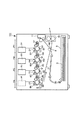
図18は、4連タンデム式の画像形成装置100における各画像形成ステーションP(PY、PM、PC、PK)での現像装置4(4Y、4M、4C、4K)及び現像剤補給装置50(50Y、50M、50C、50K)の駆動構成のレイアウトを示す。第1色、第2色、第3色及び第4色の現像装置4、現像剤補給装置50、及びその駆動機構200(200Y、200M、200C、200K)は、それぞれは図17で示した構成と同じである。図18のように4色分の現像装置4(4Y、4M、4C、4K)と現像剤補給装置50(50Y、50M、50C、50K)を連設することによってフルカラー印刷が可能である。
FIG. 18 shows a developing device 4 (4Y, 4M, 4C, 4K) and a developer replenishing device 50 (50Y) at each image forming station P (PY, PM, PC, PK) in the four-tandem
このシステムの場合、図示矢印方向に中間転写体(中間転写媒体)7又は記録材(記録紙)が移動して、各色の画像を重ねるため、図示寸法Qを中間転写体7又は記録紙が移動する時間だけ各色が遅れて作像動作を行う。 In the case of this system, the intermediate transfer member (intermediate transfer medium) 7 or the recording material (recording paper) moves in the direction of the arrow in the figure, and the intermediate transfer member 7 or the recording sheet moves to the dimension Q shown in FIG. Each color is delayed for the amount of time to perform image formation.
感光ドラム1(1Y、1M、1C、1K)は記録紙又は中間転写体と接しているため常に回転しているが、現像装置4内の現像剤撹拌手段としての攪拌スクリュー45と現像スクリュー44は現像剤の劣化を最小限にするため作像動作中の必要な時間だけしか回転させないことが一般的である。現像装置4内の攪拌スクリューと現像スクリューが停止した状態で、サブトナー容器から現像装置へトナーを補給する動作を行うと、補給されたトナーが補給口付近で停滞しトナーのつまりや現像装置内のT/C比の不均一の原因となるため、必ず現像装置内の攪拌スクリューと現像スクリューが回転している状態で、サブトナー容器から現像装置へトナーを補給する動作を行うことが必須である。
The photosensitive drum 1 (1Y, 1M, 1C, 1K) is always rotating because it is in contact with the recording paper or the intermediate transfer member. However, the stirring
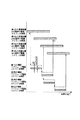
図19は、現像装置内の攪拌スクリューと現像スクリューが回転している時間を示したもので、図示Tは、図18のQ寸法を記録紙又は中間転写体が移動する時間に対応している。従って、図19の通り、各色の現像装置内の攪拌スクリューと現像スクリューが回転している間に、対応する現像剤補給装置のトナー補給手段としての補給スクリューが回転してサブトナー容器から現像装置へトナーを補給する動作を行うことになる。 FIG. 19 shows the time during which the agitating screw and the developing screw in the developing device are rotating, and T shown in the drawing corresponds to the time when the recording paper or the intermediate transfer member moves along the Q dimension in FIG. . Accordingly, as shown in FIG. 19, while the stirring screw and the developing screw in each color developing device are rotating, the replenishing screw as the toner replenishing means of the corresponding developer replenishing device is rotated to move from the sub toner container to the developing device. An operation of replenishing toner is performed.
従来の画像形成装置には、各色最適なタイミングでサブトナー容器から現像装置へトナーを補給するための補給スクリューの回転駆動源となるモータが補給スクリューの数だけ必要であった。 The conventional image forming apparatus requires as many motors as rotation driving sources of the supply screw for supplying toner from the sub-toner container to the developing device at the optimal timing for each color.
このために4色の多重現像を行うとすると、補給手段を駆動するだけで4個のモータが必要であった。例えばいくつかのモータを共通にして電磁クラッチを利用して回転と停止を切り換えることも可能であるが、結局モータの代わりに電磁クラッチが必要になることはいうまでもない。 For this reason, when four-color multiple development is performed, four motors are required only by driving the replenishing means. For example, it is possible to switch between rotation and stop using an electromagnetic clutch with some motors in common, but it goes without saying that an electromagnetic clutch is required instead of the motor.
例えば、特許文献1は、1つの駆動モータで、モータの回転方向により駆動側を選択して切換え、それによって、2つのトナーコンテナの各々の現像剤補給ローラーを駆動する構成とした現像剤補給機構を開示している。また、駆動切換方法としては、揺動ギヤや、ワンウェイクラッチなどを用いている。この構成により、モータの数を減らすことができる。
For example,
しかしながら、特許文献1には、現像装置内の攪拌スクリュー及び現像スクリューの回転状態と、現像剤補給装置の補給スクリューの作動状態との関係、即ち、駆動切換タイミングについては、何らの記載もない。
However,
本発明者らの多くの研究実験の結果によれば、駆動切換タイミングは、現像剤の撹拌不良による現像剤飛散や、地かぶり、濃度変動を抑制し、良好な画像を得るためには、各種情報に応じて最適化することが極めて重要であることが分かった。
本発明は、従来のトナー補給手段の駆動構成を更に発展させたものであって、1つの駆動源で2つの現像剤補給装置からの補給用現像剤の補給を、駆動切換により行う画像形成装置において、駆動切換タイミングを画像に応じて変更可能に構成し、駆動切換タイミングの最適化を図ることのできる画像形成装置を提供することを目的とする。 The present invention is a further development of the driving structure of a conventional toner replenishing means, and an image forming apparatus that replenishes replenishment developer from two developer replenishing devices with one drive source by drive switching. An object of the present invention is to provide an image forming apparatus in which the drive switching timing can be changed according to the image, and the drive switching timing can be optimized.
本発明の他の目的は、機構を極端に複雑化することなく、大型で高価な部品であるモータや電磁クラッチを削減し、構成が簡素で小型・低価格であると共に、現像剤の撹拌不良による現像剤飛散や、地かぶり、濃度変動を抑制し、良好な画像を得ることのできる画像形成装置を提供することである。 Another object of the present invention is to reduce motors and electromagnetic clutches, which are large and expensive parts, without complicating the mechanism extremely, and with a simple structure, small size and low price, and poor developer agitation. It is an object of the present invention to provide an image forming apparatus capable of obtaining a good image by suppressing developer scattering, ground fogging, and density fluctuations.
上記諸目的は本発明に係る画像形成装置にて達成される。本発明によれば、
第1の像担持体上に形成された静電像を現像剤で現像する第1の現像装置と、
前記第1の現像装置の駆動中に駆動が開始され、前記第1の像担持体にて形成された画像の移動方向下流側に設けられた第2の像担持体上に形成された静電像を現像剤で現像する第2の現像装置と、
前記第1の現像装置へ補給すべき現像剤を収容する第1の現像剤容器と、
前記第2の現像装置へ補給すべき現像剤を収容する第2の現像剤容器と、
前記第1の現像剤容器に設けられ、前記第1の現像装置の駆動中に前記第1の現像剤容器内の現像剤を前記第1の現像装置へ補給する第1の補給手段と、
前記第2の現像剤容器に設けられ、前記第2の現像装置の駆動中に前記第2の現像剤容器内の現像剤を前記第2の現像装置へ補給する第2の補給手段と、
前記第1の補給手段と前記第2の補給手段の各々に選択的に駆動入力可能な同一の回転駆動源と、
前記第1及び前記第2の現像装置が同時に駆動されている画像形成期間中において、前記第1の現像装置及び前記第2の現像装置にて現像すべき画像の濃度比率に基づいて、前記回転駆動源の駆動を前記第1の補給手段と前記第2の補給手段に選択的に切り替えるタイミングを変更する制御部と、を有することを特徴とする画像形成装置が提供される。
The above objects are achieved by the image forming apparatus according to the present invention. According to the present invention,
The first developing device for developing an electrostatic image formed on the first image bearing member in the current image agent,
Driving is started during the driving of the first developing device, and the electrostatic image formed on the second image carrier provided on the downstream side in the moving direction of the image formed on the first image carrier. a second developing device for developing at the current image agent image,
A first developer container containing a current image agent-out supply all to the first developing device,
A second developer container containing a current image agent-out supply all to the second developing device,
Provided in the first developer container, a first replenishing means for replenishing the current image agent of the first developer container to the first developing device during driving of the first developing device,
Provided in the second developer container, and a second replenishing means for replenishing the current image agent of the second developer container to the second developing device during driving of the second developing device,
The same rotational drive source capable of selectively driving input to each of the first supply means and the second supply means ;
During the image forming period in which the first and second developing devices are driven simultaneously, the rotation is performed based on the density ratio of the image to be developed by the first developing device and the second developing device. There is provided an image forming apparatus comprising: a control unit that changes a timing of selectively switching driving of the driving source between the first supply unit and the second supply unit .
本発明によれば、
(1)1つの駆動源で2つの現像剤補給装置からの補給用現像剤の補給を、駆動切換により行う画像形成装置において、駆動切換タイミングを画像に応じて変更可能に構成し、駆動切換タイミングの最適化を図ることができる。
(2)機構を極端に複雑化することなく、大型で高価な部品であるモータや電磁クラッチを削減し、構成が簡素で小型・低価格であると共に、現像剤の撹拌不良による現像剤飛散や、地かぶり、濃度変動を抑制し、良好な画像を得ることができる。
といった効果を奏し得る。
According to the present invention,
(1) In an image forming apparatus that replenishes replenishment developer from two developer replenishing devices with one drive source by drive switching, the drive switching timing can be changed according to the image, and the drive switching timing Can be optimized.
(2) The motor and electromagnetic clutch, which are large and expensive parts, are reduced without making the mechanism extremely complicated, and the configuration is simple, small and low-priced. Further, it is possible to suppress ground fog and density fluctuation and obtain a good image.
Such effects can be achieved.
以下、本発明に係る画像形成装置を図面に則して更に詳しく説明する。 The image forming apparatus according to the present invention will be described below in more detail with reference to the drawings.
実施例1
以下、本発明の画像形成装置を実施例に則して説明するが、本実施例で使用する現像装置及び現像剤補給装置の構成及び作用は、先に図16、図17に関連して説明した従来例と同様であるので、先の説明を援用する。従って、以下の説明では、主として、本発明の特徴である、現像剤補給装置の駆動構成及び作動態様を従来例と比較して説明する。
Example 1
Hereinafter, the image forming apparatus of the present invention will be described with reference to the embodiments. The configurations and operations of the developing device and the developer supply device used in the present embodiment will be described with reference to FIGS. Since it is the same as that of the conventional example, the previous explanation is used. Therefore, in the following description, the driving configuration and operation mode of the developer replenishing device, which is a feature of the present invention, will be mainly described in comparison with the conventional example.
(画像形成装置の全体構成及び動作)
先ず、図1を参照して本発明に係る画像形成装置の一実施例の全体構成及び動作について説明する。本実施例にて画像形成装置は、電子写真方式のカラー画像形成装置とされる。
(Overall configuration and operation of image forming apparatus)
First, the overall configuration and operation of an embodiment of an image forming apparatus according to the present invention will be described with reference to FIG. In this embodiment, the image forming apparatus is an electrophotographic color image forming apparatus.
本実施例の画像形成装置100は、画像形成装置本体(装置本体)に接続された原稿読み取り装置或いは装置本体に通信可能に接続されたパーソナルコンピュータ等のホスト機器からの画像情報に従って、イエロー(Y)、マゼンタ(M)、シアン(C)、ブラック(K)の4色フルカラー画像を、電子写真方式を利用して記録材(記録紙、プラスチックシート、布等)に形成することができる。
The
本実施例の画像形成装置100は、4連タンデム式の画像形成装置であって、複数の画像形成部として第1、第2、第3、第4の画像形成ステーションP(PY、PM、PC、PK)を有する。又、本実施例の画像形成装置100は、中間転写方式を採用している。つまり、中間転写体としての周回移動(回転)可能な中間転写ベルト7が図示矢印方向に移動して、各画像形成ステーションPを通過する間に、中間転写ベルト7上に各色の画像が重ねられる。そして、この中間転写ベルト7上で各色が重ね合わされたトナー像を記録材Sに転写することで記録画像を得る。
The
本実施例では、各画像形成ステーションP(PY、PM、PC、PK)の構成は、現像色が異なる以外は実質的に同一とされるので、以下、特に区別を要しない場合は、何れかの画像形成ステーションに属する要素であることを示すために符号に与えた添え字Y、M、C、Kは省略し、総括的に説明する。 In this embodiment, the configuration of each image forming station P (PY, PM, PC, PK) is substantially the same except that the development colors are different. The subscripts Y, M, C, and K given to the reference numerals to indicate that they belong to the image forming station will be omitted and will be described generally.
各画像形成ステーションPは、像担持体としてのドラム状の電子写真感光体(以下、「感光ドラム」という。)1を有する。感光ドラム1の外周には、帯電手段としての帯電ローラ2、露光手段としての露光装置(本実施例ではレーザー露光光学系)3、現像手段としての現像装置4、クリーニング手段としてのクリーニング装置6が設けられている。又、中間転写ベルト7を介して感光ドラム1と対向するように一次転写手段としての一次転写ローラ5が配置されている。
Each image forming station P has a drum-shaped electrophotographic photosensitive member (hereinafter referred to as “photosensitive drum”) 1 as an image carrier. On the outer periphery of the
画像形成時には、回転する感光ドラム1を帯電ローラ2が一様に帯電させる。次いで、帯電された感光ドラム1の表面を、露光装置3が画像情報信号に応じて走査露光する。これにより、感光ドラム1上に静電像が形成される。感光ドラム1に形成された静電像は、現像装置4によって現像剤でトナー像として現像される。その後、感光ドラム1上に形成されたトナー像は、中間転写ベルト7と感光ドラム1とが当接する1次転写部(ニップ)N1において、中間転写ベルト7上に転写される。
At the time of image formation, the charging roller 2 uniformly charges the rotating
例えば、4色フルカラー画像の形成時には、第1の画像形成ステーションPYから順次に、中間転写ベルト7が各感光ドラム1間の距離Q(図18参照)を移動する時間だけ遅れて各画像形成ステーションにて作像動作が行われる。これにより、中間転写ベルト7の移動に伴って、各画像形成ステーションPの1次転写部N1において順次各色のトナー像が中間転写ベルト7に転写され、中間転写ベルト7上に4色のトナー像が重ね合わされた多重トナー像が形成される。
For example, when a four-color full-color image is formed, each image forming station is delayed by the time required for the intermediate transfer belt 7 to move the distance Q (see FIG. 18) between the
一方、例えば、記録材収容部としてのカセット9に収容されている記録材Sが、ピックアップローラ、搬送ローラ及びレジストローラ等の記録材搬送部材によって、中間転写ベルト7と二次転写手段としての二次転写ローラ8とが当接する二次転写部(ニップ部)N2に、中間転写ベルト7上のトナー像と同期がとられて搬送されてくる。
On the other hand, for example, the recording material S accommodated in the cassette 9 as the recording material accommodation portion is transferred to the intermediate transfer belt 7 and the secondary transfer means by a recording material conveying member such as a pickup roller, a conveying roller, and a registration roller. The toner image on the intermediate transfer belt 7 is synchronized with the toner image on the secondary transfer portion (nip portion) N2 where the
こうして、中間転写ベルト7上の多重トナー像は、二次転写部N2において記録材S上に転写される。その後、記録材Sは、中間転写ベルト7から分離されて、定着器10へと搬送される。定着器10によって記録材Sは加熱、加圧され、記録材S上の未定着のトナー像が定着される。その後、記録材Sは、機外へ排出される。
Thus, the multiple toner images on the intermediate transfer belt 7 are transferred onto the recording material S at the secondary transfer portion N2. Thereafter, the recording material S is separated from the intermediate transfer belt 7 and conveyed to the fixing
一次転写工程後に感光ドラム1上に残留したトナー等の付着物は、クリーニング装置6によって除去される。又、二次転写工程後に中間転写ベルト7上に残留したトナー等の付着物は中間転写体クリーナ11によって除去される。
Deposits such as toner remaining on the
尚、例えばブラック単色の画像など、所望の単色又は4色のうちいくつかの色用の画像形成部を用いて、単色又はマルチカラーの画像を形成することも可能である。 Note that it is also possible to form a single color or multi-color image by using an image forming unit for a desired single color or some of four colors such as a black single color image.
又、本実施例では、画像形成装置100は、中間転写方式を採用するものとして説明するが、本発明はこれに限定されるものではない。当業者には周知のように、上記中間転写体7の代わりに、記録材を担持して各感光ドラム1とのニップ部へ搬送する記録材担持体を備えた画像形成装置がある。この場合、各画像形成ステーションにおいて、記録材担持体上の記録材に各色のトナー像が多重転写され、その後この多重トナー像を定着させることで記録画像を得る。本発明は、斯かる画像形成装置においても等しく適用可能である。
In this embodiment, the
(現像装置及び現像剤補給装置の駆動構成及び動作)
次に、図2を参照して現像装置4及び現像剤補給装置50の駆動構成について説明する。
(Driving device and developer supply device drive configuration and operation)
Next, with reference to FIG. 2, the drive configuration of the developing
本実施例では、上述したように、各画像形成ステーションP(PY、PM、PC、PK)の構成は、現像色が異なる以外は実質的に同一とされ、現像装置4(4Y、4M、4C、4K)及び現像剤補給装置50(50Y、50M、50C、50K)も同様の構成とされる。 In this embodiment, as described above, the configuration of each image forming station P (PY, PM, PC, PK) is substantially the same except that the development colors are different, and the developing device 4 (4Y, 4M, 4C). 4K) and the developer supply device 50 (50Y, 50M, 50C, 50K) have the same configuration.
また、上述のように、本実施例で使用する現像装置4及び現像剤補給装置50の構成及び作用は、先に図16に関連して説明した従来例と同様であるので、先の説明を援用するが、現像装置4及び現像剤補給装置50の構成及び作用について簡単に説明すると、次の通りである。
Further, as described above, the configurations and operations of the developing
つまり、図16及びその関連の説明をも参照すると理解されるように、現像装置4は、内部に蓄えた現像剤を用いて感光ドラム1上の静電像を可視像に現像可能である。
That is, as understood with reference to FIG. 16 and the related description, the developing
即ち、現像装置4は、現像装置4内の現像剤を攪拌・搬送する現像剤攪拌手段である現像スクリュー44及び攪拌スクリュー45を有する。又、現像剤補給装置50は、上述のように、現像装置4へ補給すべき補給用現像剤(トナー)を収容する第1の現像剤容器としてのサブトナー容器51、サブトナー容器51からトナーを排出し現像装置4へ補給する第1の補給手段としての補給スクリュー53、サブトナー容器51へ補給すべきトナーを貯蔵する第2の現像剤容器としてのメイントナー容器57、メイントナー容器57からトナーを排出しサブトナー容器51へ補給する第2の補給手段としての攪拌搬送部材58を有する。
That is, the developing
本実施例によると、イエロー画像形成ステーションPYと、画像作成方向に関し該イエロー画像形成ステーションPYより下流側に位置したマゼンタ画像形成ステーションPMとにそれぞれ設けられたイエロー現像装置(第1の現像装置)4Yとマゼンタ現像装置(第2の現像装置)4Mの現像剤補給装置50Y及び50Mは、第1の駆動機構200Aにて駆動される。また、同様に、シアン画像形成ステーションPCと、画像作成方向に関し該シアン画像形成ステーションPCより下流側に位置したブラック画像形成ステーションPKとにそれぞれ設けられたシアン現像装置(第1の現像装置)4Cとブラック現像装置(第2の現像装置)4Kの現像剤補給装置50C及び50Kは、第2の駆動機構200Bにて駆動される。第1の駆動機構200Aと第1の駆動機構200Bとは同様の構成及び機能を有しており、従って、以下に、第1の駆動機構200Aについて説明する。
According to this embodiment, the yellow developing device (first developing device) provided in each of the yellow image forming station PY and the magenta image forming station PM located downstream from the yellow image forming station PY in the image forming direction. The
現像剤補給装置50の駆動機構200Aは、補給スクリュー53へ駆動伝達が可能な回転駆動手段であるモータ80、モータ80の回転を補給スクリュー53へ伝達可能な回転伝達手段としての駆動ギア列GTを有する。
The
撹拌搬送部材58は、従来と同様に、前記モータ80から駆動ギヤ列(図示せず)を介して駆動ギア59に駆動伝達することもできるが、前記モータ80とは別のモータを使用して駆動することも可能である。
The agitating / conveying
更に説明すると、補給スクリュー53へ駆動伝達するための駆動ギア列GTは、モータ80側の第1駆動ギア81、この第1駆動ギア81に噛合する第2及び第3駆動ギア82、83を有する。第2駆動ギア82は、第1の現像装置(即ち、イエロー現像装置)4Yの補給スクリュー53側に駆動を伝達するために、第1現像装置4Y側の第1スクリューギア71に噛合する。また、第3駆動ギア83は、第2の現像装置(即ち、マゼンタ現像装置)4Mの補給スクリュー53側に駆動を伝達するために、第4駆動ギア84を介して第2現像装置4M側の第1スクリューギア71に噛合する。
More specifically, the drive gear train GT for transmitting the drive to the
第1及び第2の現像装置4Y、4Mにて、第1スクリューギア71は、一方向クラッチ8a、8bを介して第2スクリューギア70に噛合し、該ギア70は、補給スクリュー53を駆動するスクリュー駆動ギア54に噛合している。
In the first and second developing
本実施例によると、詳しくは後述するように、駆動ギア列GTは、モータ80の回転を第1の現像装置4Yに対する補給スクリュー53へ伝達可能な第1の状態と、第2の現像装置4Mに対する補給スクリュー53へ伝達可能な第2の状態と切り換え可能な切り換え手段として機能する。
According to the present embodiment, as will be described in detail later, the drive gear train GT can transmit the rotation of the
制御手段90が、モータ80の正逆回転と停止を制御する。又、制御手段90は、現像装置4の現像剤撹拌手段、即ち、現像スクリュー44、搬送スクリュー45の回転、停止をも制御する。
The control means 90 controls forward / reverse rotation and stop of the
また、上記一方向クラッチ8aと8bは、それぞれ図示の方向の回転は伝達するが、反対方向の回転は伝達しない構成になっている。従って、モータ80が図示Aの方向に回転すると一方向クラッチ8aは駆動を伝達し、一方向クラッチ8bは空転し、逆にモータ80が図示Bの方向に回転すると一方向クラッチ8bは駆動を伝達し、一方向クラッチ8aは空転する。
The one-
この結果、モータ80が図示A方向に回転すると第2の現像装置4M側の補給スクリュー53が停止したままで、第1の現像装置4Yの補給スクリュー53が回転し、モータ80が図示B方向に回転すると第1の現像装置4Yの補給スクリュー53が停止したままで、第2の現像装置4M側の補給スクリュー53が回転する。
As a result, when the
このように、駆動ギア列GTは一方向クラッチ8a、8bを含んでいるので、制御手段90がモータ80の回転方向を切り換えることによって、モータ80の回転を第1の現像装置4Y側の補給スクリュー53へ伝達可能な第1の状態と、第2の現像装置4M側の補給スクリュー53へ伝達可能な第2の状態の2つの状態に切り換え可能な切り換え手段の作用をすることができる。つまり、切り換え手段は、1つの画像の形成動作中において、モータ80の駆動力を第1の現像装置4Y側の補給スクリュー53へ駆動伝達可能な第1の状態と、第2の現像装置4M側の補給スクリュー53へ駆動伝達可能な第2の状態の、少なくとも2つの状態で使用すべくこれらを切り換えることができる。又、制御手段90は、切り換え手段に作用して、1つの画像の形成動作中における前記第1の状態の時間と前記第2の状態の時間とを、形成すべき画像に応じて変更することができる。例えば、制御手段90は、第1の現像装置4Yが現像すべき画像の濃度と、第2の現像装置4Mが現像すべき画像の濃度と、に応じて第1の状態の時間と第2の状態の時間と変更することができる。
Thus, since the drive gear train GT includes the one-
以上のような構成により、第1の現像装置4Y側の補給スクリュー53を回転させてサブトナー容器51から現像装置4Yへトナーを補給する場合は、図示A方向にモータ80を回転させれば、第2の現像装置4M側の補給スクリュー53を停止させたままで第1の現像装置4Y側の補給スクリュー53を回転させることが可能である。また、第2の現像装置4M側の補給スクリュー53を回転させてサブトナー容器51から第2の現像装置4Mへトナーを補給する場合は、図示B方向にモータ80を回転させれば、第1の現像装置4Y側の補給スクリュー53を停止させたままで第2の現像装置4M側の補給スクリュー6を回転させることが可能である。従って、従来例に比べてモータが1つ削減できるので、画像形成装置の簡素化、小型化、低価格化を実現することができる。
With the configuration described above, when the
又、補給スクリュー53が回転を開始して停止するタイミングは、従来例と同様に現像装置の攪拌手段が回転している間に限定されている。
Further, the timing at which the replenishing
図3は、本実施例におけるタイミングを示した図であり、第1の現像装置4Yの攪拌手段44、45が回転を開始した後に補給スクリュー53の回転が開始し(図示A)、第1の現像装置4Y側の補給スクリュー53の回転が停止した後に第1の現像装置4Yの攪拌手段44、45が停止し(図示B)、第2の現像装置4Mの攪拌手段44、45が回転を開始した後に第2の現像装置4Mの補給スクリュー53の回転が開始し(図示C)、第2の現像装置4Mの補給スクリュー53の回転が停止した後に第2の現像装置4Mの攪拌手段44、45が停止する(図示D)ように制御手段90が設定されている。
FIG. 3 is a diagram showing the timing in this embodiment. After the stirring means 44 and 45 of the first developing
図3と図19を比較すると、1つの現像装置当たりに補給する時間は、図19のX9と図3のX2を比較すると本実施例の方が短くなっていることは明らかである。 Comparing FIG. 3 and FIG. 19, it is clear that the time required for replenishing per developing device is shorter in this embodiment when comparing X9 in FIG. 19 and X2 in FIG.
これは、従来各現像装置にモータを設けていたのに対して、本実施例では2つの現像装置に対して1つのモータしか設けていないためであることは言うまでもない。 Needless to say, this is because, in the present embodiment, only one motor is provided for two developing devices, whereas each developing device is conventionally provided with a motor.
しかし、このように補給時間が短い場合であっても、最大印刷範囲に最高濃度の印刷をした場合のトナーを所定時間内に現像装置へ補給できなければ、現像装置内のT/Cを一定に保つことができない。 However, even if the replenishment time is short, if the toner at the maximum density in the maximum printing range cannot be replenished to the developing device within a predetermined time, the T / C in the developing device is kept constant. Can't keep up.
従って、本実施例の画像形成装置では従来の画像形成装置より補給時間が短縮された割合に対して反比例して単位時間当たりのトナーの補給量を多くしなければならない。 Therefore, in the image forming apparatus of the present embodiment, the amount of toner replenished per unit time has to be increased in inverse proportion to the rate at which the replenishment time is shortened compared to the conventional image forming apparatus.
図3と図19の図示Y2とY9は、それぞれ単位時間当たりのトナーの補給量を示しており、図3においてX9に対してX2が短くなった割合に反比例して、Y9に対してY2が増加しており、補給可能なトナー量を示すX2とY2の積、X9とY9の積(斜線部の面積)は、図3と図19で等しくなっている。 Y2 and Y9 in FIG. 3 and FIG. 19 indicate the amount of toner replenished per unit time, respectively. In FIG. 3, Y2 is in proportion to Y9 in inverse proportion to the ratio of X2 to X9. The product of X2 and Y2 and the product of X9 and Y9 (area of the shaded area) indicating the amount of toner that can be replenished are equal in FIG. 3 and FIG.
このように、本実施例では単位時間の補給量を増やすことで所定の時間内に従来例と同量のトナーが補給可能になっている。 As described above, in this embodiment, by increasing the replenishment amount per unit time, the same amount of toner as in the conventional example can be replenished within a predetermined time.
しかしながら、単位時間当たりのトナーの補給量を増やすと一般に補給精度が低下し、かつ、トナーの補給が一箇所に集中するので現像装置内のT/C比が均一になり難いという弊害が少なからずあるため、可及的に単位時間当たりのトナーの補給量は少ない方が望ましい。 However, when the amount of toner replenished per unit time is increased, the replenishment accuracy generally decreases, and toner replenishment is concentrated in one place, so that there is a considerable problem that the T / C ratio in the developing device is difficult to become uniform. Therefore, it is desirable that the amount of toner replenished per unit time is as small as possible.
前述の斜線部に示したトナーの補給量は、最大印刷範囲に最高濃度の印刷をした場合の最大補給量を示しているので、実際に使用される実用的な画像のトナーの量は最大濃度の20%以下であることが一般的であるため、図3のような最大速度で補給する必要はない場合がほとんどである。 The toner replenishment amount shown in the shaded area above indicates the maximum replenishment amount when printing at the highest density in the maximum printing range, so the actual toner amount actually used is the maximum density. In most cases, it is not necessary to replenish at the maximum speed as shown in FIG.
このように、装置の能力としては、最大トナー使用量に対して補給速度が追従できるように設定しておくものの、例えば濃度の低い印刷を行う場合においては、補給精度の低下や現像装置内のT/C比の不均一などの弊害を可及的に抑制するため単位時間当たりのトナーの補給量を下げる制御をすることが望ましい。即ち、本実施例において、好ましくは、補給スクリューによるトナー補給量の増減を制御可能な補給量制御手段が設けられる。 As described above, the capability of the apparatus is set so that the replenishment speed can follow the maximum amount of toner used. In order to suppress as much as possible adverse effects such as non-uniformity of the T / C ratio, it is desirable to control the toner replenishment amount per unit time. That is, in this embodiment, preferably, a replenishment amount control means capable of controlling the increase and decrease of the toner replenishment amount by the replenishment screw is provided.
以下、単位時間当たりのトナーの補給量を下げることが可能になる場合とそれぞれの場合において、どの程度補給量を下げることができるかを説明する。 Hereinafter, the case where the toner supply amount per unit time can be reduced and how much the toner supply amount can be reduced in each case will be described.
単位時間当たりのトナーの補給量を下げることができる第一の場合は、印刷する画像の濃度、即ち、現像画像濃度が低い場合である。図4はその例を示した図であって、例えば最大濃度の20%の濃度の印刷しかしない場合は補給すべきトナーの量が20%で済むので図のように単位時間当たりの補給量を図3に示すトナー補給量の20%で制御している。即ち、補給量制御手段は、第1又は第2現像装置の補給スクリューによる単位時間当たりの補給量を制御する際に、該当する現像装置の現像画像濃度が高ければ補給量を増やし、現像画像濃度が低くければ補給量を減らす傾向に制御する。 The first case where the toner replenishment amount per unit time can be lowered is when the density of the image to be printed, that is, the developed image density is low. FIG. 4 is a diagram showing an example of this. For example, when printing is performed at a density of 20% of the maximum density, the amount of toner to be replenished can be 20%. Control is performed at 20% of the toner replenishment amount shown in FIG. That is, the replenishment amount control means increases the replenishment amount when the developed image density of the corresponding developing device is high when controlling the replenishment amount per unit time by the replenishment screw of the first or second developing device. If it is low, control is made to reduce the supply amount.
単位時間当たりのトナーの補給量を下げることができる第二の場合は、印刷する画像が最大印刷範囲で最高濃度であっても記録材、即ち、記録する用紙(記録紙)の幅が狭い場合である。図5のように記録する用紙の幅が狭ければ、最大印刷範囲で最高濃度の印刷をしても図示W1/W2の割合でトナーの使用量は少なくて済む。補給量制御手段は、第1又は第2の現像装置の補給スクリューによる単位時間当たりの補給量を制御する際に、感光ドラム上の可視像が転写される記録紙の主走査方向の長さが長ければ補給量を増やし、記録紙の主走査方向の長さが短かければ補給量を減らす傾向に制御する。 In the second case where the toner replenishment amount per unit time can be reduced, the width of the recording material, that is, the recording paper (recording paper) is narrow even if the image to be printed has the highest density in the maximum printing range. It is. If the width of the recording sheet is narrow as shown in FIG. 5, the amount of toner used can be reduced at the ratio of W1 / W2 shown in the figure even when the highest density printing is performed in the maximum printing range. The replenishment amount control means controls the replenishment amount per unit time by the replenishment screw of the first or second developing device, and the length in the main scanning direction of the recording paper onto which the visible image on the photosensitive drum is transferred. If the length is longer, the supply amount is increased. If the length of the recording paper in the main scanning direction is shorter, the supply amount is controlled to decrease.
図6は、その時の制御方法を示した図であって、単位時間当たりの補給量を図3に示す補給量の(W1/W2)倍で制御している。この時、濃度が低い場合は更に単位時間当たりの補給量を下げることができることはいうまでもない。 FIG. 6 is a diagram showing a control method at that time, and the replenishment amount per unit time is controlled by (W1 / W2) times the replenishment amount shown in FIG. At this time, it goes without saying that if the concentration is low, the replenishment amount per unit time can be further reduced.
単位時間当たりのトナーの補給量を下げることができる第三の場合は印刷する画像が最大印刷範囲で最高濃度で記録する用紙の幅が最大であっても記録する速度が低下している場合である。 The third case where the amount of toner replenished per unit time can be reduced is when the printing speed is reduced even if the image to be printed is at the maximum print range and the maximum width of the paper to be recorded. is there.
例えば、非常に厚い記録紙に記録する場合や、表面の粗い記録紙に記録する場合において、トナーの定着性を確保するため、印刷速度を1/2程度に下げて印刷する制御が提案されている。 For example, when recording on a very thick recording paper or recording on a recording paper with a rough surface, a control for printing at a printing speed reduced to about ½ has been proposed in order to ensure toner fixability. Yes.
図7はその例を示した図であって、例えば印刷速度が1/2に下がっている場合を示している。この場合は補給すべき時間が図のように2倍になっているので単位時間当たりの補給量を1/2にしても最大補給量と同等の補給をすることができる。即ち、補給量制御手段は、第1又は第2の現像装置の補給スクリューによる単位時間当たりの補給量を制御する際に、画像形成速度が速ければ補給量を増やし、画像形成速度が遅ければ補給量を減らす傾向に制御する。 FIG. 7 is a diagram showing an example of this, and shows a case where the printing speed is reduced to 1/2, for example. In this case, since the time to be replenished is doubled as shown in the figure, the replenishment equivalent to the maximum replenishment amount can be performed even if the replenishment amount per unit time is halved. That is, the replenishment amount control means increases the replenishment amount when the image forming speed is fast and controls the replenishment amount when the image forming speed is slow when controlling the replenishment amount per unit time by the replenishment screw of the first or second developing device. Control to reduce the amount.
この時、濃度が低い場合は更に単位時間当たりの補給量を下げることができ、記録する用紙の幅が狭い場合は更に単位時間当たりの補給量を下げることができることはいうまでもない。 At this time, it is needless to say that the supply amount per unit time can be further reduced when the density is low, and the supply amount per unit time can be further reduced when the recording paper width is narrow.
単位時間当たりのトナーの補給量を下げることができる第四の場合は、各色の濃度(印字率)が偏っている場合である。ここで言う印字率とは、形成されるべき画像領域の総画素数に占める実際に形成される画素数の割合のことである。 The fourth case where the toner replenishment amount per unit time can be lowered is when the density (printing rate) of each color is uneven. The printing rate here is the ratio of the number of pixels actually formed to the total number of pixels of the image area to be formed.
極端な例を挙げると、例えば第一色の濃度が5%、第二色の濃度が70%、第三色の濃度が50%、第四色の濃度が2%である場合は、第一色と第四色の補給時間は短く済ますことができるので、その分第二色と第三色の補給に時間をかけることが可能である。 For example, if the density of the first color is 5%, the density of the second color is 70%, the density of the third color is 50%, and the density of the fourth color is 2%, Since the replenishment time of the color and the fourth color can be shortened, it is possible to spend time for the supplementation of the second color and the third color accordingly.
図8はその例を示したもので、各色の濃度から一定のアルゴリズムで補給時間を割り振って制御することが可能である。 FIG. 8 shows an example of this, and it is possible to control by assigning the replenishment time from the density of each color with a certain algorithm.
即ち、補給量制御手段は、第1又は第2の現像装置の補給スクリューによる単位時間当たりの補給量を制御する際に、
(1)第1の現像装置の補給スクリューであれば、第2の現像装置の現像画像濃度が高ければ補給量を減らし、そして、第2の現像装置の補給スクリューであれば、第1の現像装置の現像画像濃度が高ければ補給量を減らし、また、
(2)第1の現像装置の補給スクリューであれば、第2の現像装置の現像画像濃度が低ければ補給量を増やし、そして、第2の現像装置の補給スクリューであれば、第1の現像装置の現像画像濃度が低ければ補給量を増やす、
傾向に制御する。
That is, the replenishment amount control means controls the replenishment amount per unit time by the replenishment screw of the first or second developing device.
(1) If the replenishing screw is for the first developing device, the replenishing amount is reduced if the developed image density of the second developing device is high, and if the replenishing screw is for the second developing device, the first developing is performed. If the developed image density of the device is high, the replenishment amount is reduced,
(2) If it is a replenishing screw for the first developing device, the replenishing amount is increased if the developed image density of the second developing device is low, and if it is a replenishing screw for the second developing device, the first developing is performed. Increase the replenishment amount if the developed image density of the device is low,
Control to the trend.
以上説明したような場合に単位時間当たりの補給量を下げる制御が可能であり、上記のような理論で、それぞれ各色の濃度・記録幅・印刷速度・駆動源を共有している隣接した色の濃度・等から一定のアルゴリズムで単位時間当たりの補給量を下げる制御が可能である。 In the case described above, it is possible to control the amount of replenishment per unit time to be reduced, and according to the theory as described above, the density of each color, the recording width, the printing speed, and the adjacent colors sharing the driving source are respectively controlled. It is possible to control the amount of replenishment per unit time with a fixed algorithm based on the concentration, etc.
又、例えば、補給可能範囲を前半と後半に分けるだけでなく、図9のように数回に分けて切り替えることも可能であり、この場合制御がやや複雑になり、切り替え時間が数回累積するため全体補給時間が短くなるものの、現像装置内のT/C比が均一になり難いという弊害は大きく改善される。 Further, for example, it is possible not only to divide the replenishable range into the first half and the second half, but also to switch in several times as shown in FIG. 9. In this case, the control becomes slightly complicated, and the switching time is accumulated several times. Therefore, although the total replenishment time is shortened, the adverse effect that the T / C ratio in the developing device is hardly uniform is greatly improved.
本実施例では、図1及び図2に示すように、4色分の現像装置が連設された画像形成装置であり、シアン現像装置4Cと、その隣接したブラック現像装置4Kにおいても、上記説明したイエロー現像装置4Yとマゼンタ現像装置4Mとに対する構成及び作動態様を適用し、同様の作用効果を達成することができる。
In this embodiment, as shown in FIGS. 1 and 2, the image forming apparatus is provided with four color developing devices, and the
しかしながら、本発明によれば、4色分の現像装置が連設された画像形成装置に限定されるものではなく、現像装置が2つ以上であれば同様の効果が得られるし、4色分の内2色分だけ本実施例を適用して、他の現像装置では従来の構成をとることも勿論可能である。 However, according to the present invention, it is not limited to the image forming apparatus in which the developing devices for four colors are connected in series, and if there are two or more developing devices, the same effect can be obtained, Of course, it is possible to apply the present embodiment to only two of these colors and to adopt the conventional configuration in other developing apparatuses.
実施例2
次に、本発明の画像形成装置の第二の実施例について説明する。本実施例においても、画像形成装置、現像装置及び現像剤補給装置は、実施例1にて説明した画像形成装置、現像装置及び現像剤補給装置と同様の構成とされる。従って、画像形成装置、現像装置及び現像剤補給装置の全体構成についての詳しい説明は実施例1の説明を援用し、再度の説明は省略し、本実施例の特徴をなす現像装置及び現像剤補給装置の駆動構成及び動作について説明する。
Example 2
Next, a second embodiment of the image forming apparatus of the present invention will be described. Also in this embodiment, the image forming apparatus, the developing apparatus, and the developer supply apparatus have the same configuration as the image forming apparatus, the development apparatus, and the developer supply apparatus described in the first embodiment. Therefore, the detailed description of the overall configuration of the image forming apparatus, the developing device, and the developer supply device is referred to the description of the first embodiment, and the description of the first embodiment is omitted, and the developing device and the developer supply that characterize the present embodiment are omitted. The drive configuration and operation of the apparatus will be described.
先ず、図10を参照して、現像装置4及び現像剤補給装置50について、簡単に説明すると、現像装置4(4Y、4M、4C、4K)は、現像装置4内の現像剤を攪拌・搬送する現像剤攪拌手段である現像スクリュー44及び攪拌スクリュー45を有する。又、現像剤補給装置50(50Y、50M、50C、50K)は、上述のように、現像装置4へ補給すべき補給用現像剤(トナー)を貯蔵する第1の現像剤容器としてのサブトナー容器51、サブトナー容器51からトナーを排出し現像装置4へ補給する第1の補給手段としての補給スクリュー53、サブトナー容器51へ補給すべきトナーを貯蔵する第2の現像剤容器としてのメイントナー容器57、メイントナー容器57からトナーを排出しサブトナー容器51へ補給する第2の補給手段としての攪拌搬送部材58を有する。
First, the developing
本実施例によると、イエロー画像形成ステーションPYと、画像作成方向に関し該イエロー画像形成ステーションPYより下流側に位置したマゼンタ画像形成ステーションPMとにそれぞれ設けられたイエロー現像装置(第1の現像装置)4Yとマゼンタ現像装置(第2の現像装置)4Mの現像剤補給装置50Y及び50Mは、第1の駆動機構200Aにて駆動される。また、同様に、シアン画像形成ステーションPCと、画像作成方向に関し該シアン画像形成ステーションPCより下流側に位置したブラック画像形成ステーションPKとにそれぞれ設けられたシアン現像装置(第1の現像装置)4Cとブラック現像装置(第2の現像装置)4Kの現像剤補給装置50C及び50Kは、第2の駆動機構200Bにて駆動される。第1の駆動機構200Aと第1の駆動機構200Bとは同様の構成及び機能を有しており、従って、以下に、第1の駆動機構200Aについて説明する。
According to this embodiment, the yellow developing device (first developing device) provided in each of the yellow image forming station PY and the magenta image forming station PM located downstream from the yellow image forming station PY in the image forming direction. The
現像剤補給装置50の駆動機構200Aは、補給スクリュー53へ駆動伝達が可能な回転駆動手段であるモータ80、モータ80の回転を補給スクリュー53へ伝達可能な回転伝達手段としての駆動ギア列GTを有する。
The
なお、撹拌搬送部材58は、前記モータ80から駆動ギヤ列(図示せず)を介して駆動ギア59に駆動伝達することもできるが、前記モータ80とは別のモータを使用して駆動することも可能である。
The agitating / conveying
更に説明すると、補給スクリュー53へ駆動伝達するための駆動ギア列GTは、モータ80側の第1駆動ギア81、この第1駆動ギア81に噛合する第2駆動ギア82を有する。第2駆動ギア82は、第1駆動ギア81の回転中心を中心として揺動自在とされる揺動レバー部材85によって回転自在に支持されている。揺動レバー部材85は、第1駆動ギア81の回転方向に自動的に揺動し得るが、揺動レバー部材85を揺動駆動するために、例えば電磁ソレノイドなどの駆動手段を設けても良い。
More specifically, the drive gear train GT for transmitting the drive to the
第2駆動ギア82は、揺動レバー部材85を作動させることにより、第1の現像装置(即ち、イエロー現像装置)4Yの補給スクリュー53側に駆動を伝達するために、第1スクリューギア71に噛合するか、または、第2の現像装置(即ち、マゼンタ現像装置)4Mの補給スクリュー53側に駆動を伝達するために、第3駆動ギア83を介して第1スクリューギア71に噛合する。
The
つまり、駆動ギア列GTは、モータ80の回転を、第1の現像装置4Yの補給スクリュー53側に駆動を伝達可能な第1の状態と、第2の現像装置4Mの補給スクリュー53側に駆動を伝達可能な第2の状態の少なくとも2つの状態に切り換え可能な切り換え手段である。
That is, the drive gear train GT drives the rotation of the
制御手段90が、モータ80の正逆回転と停止を、また、必要に応じて揺動レバー部材85の揺動を制御する。又、制御手段90は、現像装置4の現像剤撹拌手段、即ち、現像スクリュー44、搬送スクリュー45の回転、停止をも制御する。
The control means 90 controls forward / reverse rotation and stop of the
この結果、モータ80が図示A1方向に回転すると、レバー部材85が図示A2方向に回動して駆動を伝達し、逆にモータ80が図示B1方向に回転すると、レバー部材85が図示B2方向に回動して駆動を伝達する。
As a result, when the
このように、駆動ギア列GTは揺動レバー部材85を含んでいるので、制御手段90がモータ80の回転方向を切り換えることによって、モータ80の回転を第1の現像装置4Y側の補給スクリュー53へ伝達可能な第1の状態と、第2の現像装置4M側の補給スクリュー53へ伝達可能な第2の状態の2つの状態に切り換え可能な切り換え手段の作用をすることができる。
Thus, since the drive gear train GT includes the
以上のような構成により、第1の現像装置4Y側の補給スクリュー53を回転させてサブトナー容器51から現像装置4Yへトナーを補給する場合は、図示A1方向にモータ80を回転させれば、第2の現像装置4M側の補給スクリュー53を停止させたままで第1の現像装置4Y側の補給スクリュー53を回転させることが可能である。また、第2の現像装置4M側の補給スクリュー53を回転させてサブトナー容器51から第2の現像装置4Mへトナーを補給する場合は、図示B1方向にモータ80を回転させれば、第1の現像装置4Y側の補給スクリュー53を停止させたままで第2の現像装置4M側の補給スクリュー6を回転させることが可能である。従って、従来例に比べてモータが1つ削減できるので、画像形成装置の簡素化、小型化、低価格化を実現することができる。
With the above configuration, when the replenishing
又、補給スクリュー53が回転を開始して停止するタイミング及びトナー補給態様は、実施例1の図3〜図9と同様であり、実施例1と同様の作用効果を奏し得る。
The timing at which the
本実施例では、図1及び図2に示すように、4色分の現像装置が連設された画像形成装置であり、シアン現像装置4Cと、その隣接したブラック現像装置4Kにおいても、上記説明したイエロー現像装置4Yとマゼンタ現像装置4Mとに対する構成及び作動態様を適用し、同様の作用効果を達成することができる。
In this embodiment, as shown in FIGS. 1 and 2, the image forming apparatus is provided with four color developing devices, and the
しかしながら、本発明によれば、4色分の現像装置が連設された画像形成装置に限定されるものではなく、現像装置が2つ以上であれば同様の効果が得られるし、4色分の内2色分だけ本実施例を適用して、他の現像装置では従来の構成をとることも勿論可能である。 However, according to the present invention, it is not limited to the image forming apparatus in which the developing devices for four colors are connected in series, and if there are two or more developing devices, the same effect can be obtained, Of course, it is possible to apply the present embodiment to only two of these colors and to adopt the conventional configuration in other developing apparatuses.
実施例3
次に、本発明の画像形成装置の第三の実施例について説明する。本実施例においても、画像形成装置、現像装置及び現像剤補給装置は、実施例1にて説明した画像形成装置、現像装置及び現像剤補給装置と同様の構成とされる。従って、画像形成装置、現像装置及び現像剤補給装置の全体構成についての詳しい説明は実施例1の説明を援用し、再度の説明は省略し、本実施例の特徴をなす現像装置及び現像剤補給装置の駆動構成及び動作について説明する。
Example 3
Next, a third embodiment of the image forming apparatus of the present invention will be described. Also in this embodiment, the image forming apparatus, the developing apparatus, and the developer supply apparatus have the same configuration as the image forming apparatus, the development apparatus, and the developer supply apparatus described in the first embodiment. Therefore, the detailed description of the overall configuration of the image forming apparatus, the developing device, and the developer supply device is referred to the description of the first embodiment, and the description of the first embodiment is omitted, and the developing device and the developer supply that characterize the present embodiment are omitted. The drive configuration and operation of the apparatus will be described.
先ず、図11を参照して、現像装置4及び現像剤補給装置50について、簡単に説明すると、現像装置4は、現像装置4内の現像剤を攪拌・搬送する現像剤攪拌手段である現像スクリュー44及び攪拌スクリュー45を有する。又、現像剤補給装置50は、上述のように、現像装置4へ補給すべき補給用現像剤(トナー)を貯蔵する第1の現像剤容器としてのサブトナー容器51、サブトナー容器51からトナーを排出し現像装置4へ補給する第1の補給手段としての補給スクリュー53、サブトナー容器51へ補給すべきトナーを貯蔵する第2の現像剤容器としてのメイントナー容器57、メイントナー容器57からトナーを排出しサブトナー容器51へ補給する第2の補給手段としての攪拌搬送部材58を有する。
First, the developing
本実施例によると、イエロー画像形成ステーションPYと、イエロー画像形成ステーションPYとは一つ置いた、且つ、画像作成方向に関し該イエロー画像形成ステーションPYより下流側に位置したシアン画像形成ステーションPCとにそれぞれ設けられたイエロー現像装置(第1の現像装置)4Yとシアン現像装置(第2の現像装置)4Cの現像剤補給装置50Y及び50Cは、第1の駆動機構200Aにて駆動される。また、同様に、マゼンタ画像形成ステーションPMと、マゼンタ画像形成ステーションPMとは一つ置いた、且つ、画像作成方向に関し該マゼンタ画像形成ステーションPMより下流側に位置したブラック画像形成ステーションPKとにそれぞれ設けられたマゼンタ現像装置(第1の現像装置)4Mとブラック現像装置(第2の現像装置)4Kの現像剤補給装置50M及び50Kは、第2の駆動機構200Bにて駆動される。第1の駆動機構200Aと第1の駆動機構200Bとは同様の構成及び機能を有しており、従って、以下に、第1の駆動機構200Aについて説明する。
According to the present embodiment, the yellow image forming station PY and the yellow image forming station PY are placed in one, and the cyan image forming station PC located downstream from the yellow image forming station PY in the image forming direction. The
現像剤補給装置50の駆動機構200Aは、補給スクリュー53へ駆動伝達が可能な回転駆動手段であるモータ80、モータ80の回転を第1の現像装置4Y側の補給スクリュー53へ伝達可能な回転伝達手段としての駆動ギア列GTと、モータ80の回転を第2の現像装置4C側の補給スクリュー53へ伝達可能な回転伝達手段としてのベルト駆動手段BTと、を有する。
The
なお、撹拌搬送部材58は、前記モータ80から駆動ギヤ列(図示せず)を介して駆動ギア59に駆動伝達することもできるが、前記モータ80とは別のモータを使用して駆動することも可能である。
The agitating / conveying
更に説明すると、第1の現像装置(即ち、イエロー現像装置)4Y側の補給スクリュー53へ駆動伝達するための駆動ギア列GTは、モータ80側の第1駆動ギア81、この第1駆動ギア81に噛合する第2及び第3駆動ギア82、83を有する。第3駆動ギア83は、第1の現像装置4Yの補給スクリュー53側に駆動を伝達するために、第1スクリューギア71に噛合する。第1スクリューギア71は、第2スクリューギア70及び第3スクリューギア54を介して補給スクリュー53を駆動する。
More specifically, the drive gear train GT for transmitting the drive to the
また、第2駆動ギア82は、第2の現像装置(即ち、シアン現像装置)4Cの補給スクリュー53側に駆動を伝達するために、一方向クラッチ87を介してベルト駆動手段BTを構成するホイール、例えば歯付きホイール86に接続されている。
Further, the
ベルト駆動手段BTは、上記歯付きホイール86と、第2の現像装置4C側に配置された歯付きホイール88と、両ホイール86、88の間に巻回されたベルト、即ち、歯付きベルト89と、を有する。歯付きホイール88は、第2の現像装置4C側の第3駆動ギア83に接続されている。
The belt driving means BT includes a toothed wheel 86, a
つまり、本実施例によると、駆動ギア列GT及びベルト駆動手段BTは、モータ80の回転を第1の現像装置4Yに対する補給スクリュー53へ伝達可能な第1の状態と、第2の現像装置4Cに対する補給スクリュー53へ伝達可能な第2の状態と切り換え可能な切り換え手段である。
That is, according to the present embodiment, the driving gear train GT and the belt driving unit BT can transmit the rotation of the
制御手段90が、モータ80の正逆回転と停止を制御する。又、制御手段90は、現像装置4の現像剤撹拌手段、即ち、現像スクリュー44、搬送スクリュー45の回転、停止をも制御する。
The control means 90 controls forward / reverse rotation and stop of the
また、上記一方向クラッチ87は、一方向の回転は伝達するが、反対方向の回転は伝達しない構成になっているので、モータ80が図示Aの方向に回転すると一方向クラッチ87は空転し、逆にモータ80が図示Bの方向に回転すると一方向クラッチ8bは、第2駆動ギア82の駆動力をホイール86に伝達する。
The one-way clutch 87 is configured to transmit rotation in one direction but not to rotate in the opposite direction. Therefore, when the
この結果、モータ80が図示A方向に回転すると第2の現像装置4C側の補給スクリュー53が停止したままで、第1の現像装置4Yの補給スクリュー53が回転し、モータ80が図示B方向に回転すると第1の現像装置4Yの補給スクリュ−53が停止したままで、第2の現像装置4C側の補給スクリュー53が回転する。
As a result, when the
このように、駆動ギア列GT及びベルト駆動手段BTは一方向クラッチ87を含んでいるので、制御手段90がモータ80の回転方向を切り換えることによって、モータ80の回転を第1の現像装置4Y側の補給スクリュー53へ伝達可能な第1の状態と、第2の現像装置4C側の補給スクリュー53へ伝達可能な第2の状態の2つの状態に切り換え可能な切り換え手段の作用をすることができる。
Thus, since the drive gear train GT and the belt drive means BT include the one-way clutch 87, the control means 90 switches the rotation direction of the
以上のような構成により、第1の現像装置4Y側の補給スクリュー53を回転させてサブトナー容器51から現像装置4Yへトナーを補給する場合は、図示A方向にモータ80を回転させれば、第2の現像装置4C側の補給スクリュー53を停止させたままで第1の現像装置4Y側の補給スクリュー53を回転させることが可能である。また、第2の現像装置4C側の補給スクリュー53を回転させてサブトナー容器51から第2の現像装置4Cへトナーを補給する場合は、図示B方向にモータ80を回転させれば、第1の現像装置4Y側の補給スクリュー53を停止させたままで第2の現像装置4C側の補給スクリュー53を回転させることが可能である。従って、従来例に比べてモータが1つ削減できるので、画像形成装置の簡素化、小型化、低価格化を実現することができる。
With the configuration described above, when the
本実施例においても、補給スクリュー53が回転を開始して停止するタイミングは実施例1と同様に現像装置4の攪拌手段44、45が回転している間に限定されている。
Also in this embodiment, the timing at which the
つまり、図12はそのタイミングを示した図であり、第1の現像装置4Yの攪拌手段44、45が回転を開始した後に第1の現像装置4Yの補給スクリュー53の回転が開始し(図示A)、第1の現像装置4Yの補給スクリュー53の回転が停止した後に第1の現像装置4Yの攪拌手段44、45が停止し(図示B)、第2の現像装置4Cの攪拌手段44、45が回転を開始した後に第2の現像装置4Cの補給スクリュー53の回転が開始し(図示C)、第2の現像装置4Cの補給スクリュー53の回転が停止した後に第2の現像装置4Cの攪拌手段44、45が停止する(図示D)ように制御手段90が設定されている。
That is, FIG. 12 is a diagram showing the timing, and the rotation of the replenishing
上記本実施例の作動態様は、図3に示す作動態様と比較すると、補給スクリュー53を回転することができる時間が長くなっていることが解かる。 It can be seen that the operation mode of the present embodiment is longer than the operation mode shown in FIG.
これは、補給スクリュー53を駆動させるモータ80を共用する組み合わせを互いに隣接した現像装置でなく、タイミングベルトを利用して1つ離れた現像装置と組み合わせているからである。
This is because the combination sharing the
補給スクリュー53を回転させる時間を長く確保できるということは、補給スクリュー53の速度を落とすことができるため、
(1)モータ80の消費電力を下げることができる、
(2)補給精度を向上させることができる、
(3)少量ずつ現像装置へ送り込むので現像装置内のトナーの濃度むらが生じにくい、
等のメリットがある。
The fact that the time for rotating the
(1) The power consumption of the
(2) The replenishment accuracy can be improved.
(3) Since the toner is sent to the developing device little by little, uneven toner density in the developing device is unlikely to occur.
There are merits such as.
従って、本実施例では、駆動ギア列GT及びベルト駆動手段BTを必要とし、実施例1と比較して機構は複雑になるものの、製品の高品質化を図ることができる。 Therefore, in the present embodiment, the drive gear train GT and the belt drive means BT are required, and although the mechanism is complicated as compared with the first embodiment, the quality of the product can be improved.
また、本実施例においても、実施例1と同様に、図4〜図9に示すトナー補給態様を適用することができ、実施例1と同様の作用効果を達成することができる。 Also in this embodiment, similarly to the first embodiment, the toner replenishing modes shown in FIGS. 4 to 9 can be applied, and the same effect as the first embodiment can be achieved.
本実施例では、図11に示すように、4色分の現像装置が連設された画像形成装置であり、マゼンタ現像装置4Mと、1つ離れたブラック現像装置4Kにおいても、上記説明したイエロー現像装置4Yとシアン現像装置4Cとに対する構成及び作動態様を適用し、同様の作用効果を達成することができる。
In this embodiment, as shown in FIG. 11, the developing device for four colors is connected in series, and the
しかしながら、本発明によれば、4色分の現像装置が連設された画像形成装置に限定されるものではなく、現像装置が3つ以上であれば同様の効果が得られるし、4色分の内2色分だけ本実施例を適用して、他の現像装置では従来の構成をとることも勿論可能である。 However, according to the present invention, the present invention is not limited to the image forming apparatus in which the developing devices for four colors are continuously provided, and the same effect can be obtained if there are three or more developing devices. Of course, it is possible to apply the present embodiment to only two of these colors and to adopt the conventional configuration in other developing apparatuses.
実施例4
次に、本発明の画像形成装置の第四の実施例について説明する。本実施例においても、画像形成装置、現像装置及び現像剤補給装置は、図1及び図2を参照して実施例1にて説明した画像形成装置、現像装置及び現像剤補給装置と同様の構成とされる。従って、画像形成装置、現像装置及び現像剤補給装置の全体構成についての詳しい説明は実施例1の説明を援用し、再度の説明は省略し、本実施例の特徴をなす現像装置及び現像剤補給装置の駆動構成及び動作について説明する。
Example 4
Next, a description will be given of a fourth embodiment of the image forming apparatus of the present invention. Also in this embodiment, the image forming apparatus, the developing apparatus, and the developer replenishing apparatus have the same configurations as the image forming apparatus, the developing apparatus, and the developer replenishing apparatus described in the first embodiment with reference to FIGS. It is said. Therefore, the detailed description of the overall configuration of the image forming apparatus, the developing device, and the developer supply device is referred to the description of the first embodiment, and the description of the first embodiment is omitted, and the developing device and the developer supply that characterize the present embodiment are omitted. The drive configuration and operation of the apparatus will be described.
図13は、本実施例における現像装置及び現像剤補給装置の制御態様を示す作動タイミング図である。 FIG. 13 is an operation timing chart showing a control mode of the developing device and the developer supply device in this embodiment.
実施例1において、図2に示したように、第1の現像装置、即ち、イエロー現像装置4Y側の補給スクリュー53と、第2の現像装置、即ち、マゼンタ現像装置4M側の補給スクリュー53に対して駆動は1つのモータ80だけであるので、図13に示すように、この2色のトナー補給可能時間は合わせてA−Dまでの時間である。
In the first embodiment, as shown in FIG. 2, the first developing device, that is, the replenishing
また、各色毎の最大補給を各色毎の作像時間とすることで、最大限の補給時間を使用し、撹拌時間を十分に取るようにする。 Further, by making the maximum replenishment for each color the image forming time for each color, the maximum replenishment time is used and sufficient stirring time is taken.
ここで、A−B間(a)、C−D間(c)は、この2色の、即ち、イエロー感光ドラム1Yと1Mのドラム間距離(図19の距離Q)であり、作像を行う上で発生するディレイ時間である。B−C間(b)は2色が同時に作像を行う時間帯である。隣り合う感光ドラム1の間隔を全て同じに設定とすると、各色の最大補給可能時間はA−C間(=B−D間)であり、イエロー現像装置4Yはt=a+b、マゼンタ現像装置4Mは、t=b+cが最大補給可能時間となる。そして、各現像装置において必要とされるトナー補給時間は、各現像装置が現像すべき画像濃度(印字率)により決定される。すなわち、画像濃度が高いほど、消費されるトナー量が多くなるため、補給すべきトナー量を増やすように補給時間は長くなる。
Here, the distance between A and B (a) and the distance between C and D (c) are the distances between these two colors, that is, the yellow
本実施例では、モータ80の正逆回転の切り替えポイントをB−C間で可変とすることで、各現像装置にとって必要量をフレキシブルに補給することが可能となる。
In this embodiment, by making the forward / reverse rotation switching point of the
基準の切り替えポイントを点Bであるとした時、以下の様に場合分けする。
(1)イエロー現像装置4Yの補給時間はtyが、ty<a、の時、切り替えポイントは点Bのままである。
(2)イエロー現像装置4Yの補給時間tyが、a+b>ty>a、かつ、マゼンタ現像装置4Mの補給時間tmが、tm<cの時は、切り替えポイントはB−C間であり、tyが終了次第、回転方向が逆転しtm分を補給する。
(3)イエロー現像装置4Yの補給時間tyが、a+b>ty>a、かつ、マゼンタ現像装置4Mの補給時間tmが、tm>cの時は、モータ80における駆動可能時間をトナー補給時間の総和が越えている。
When the reference switching point is point B, the case is divided as follows.
(1) The replenishment time of the yellow developing
(2) When the replenishment time ty of the yellow developing
(3) When the replenishment time ty of the yellow developing
本実施例では特に上記(3)の場合に対応する。 In this embodiment, the case (3) is particularly dealt with.
トナー補給の切り替えポイントはB−C間とし、トナー補給時間ty、tmの比分によって切り替えポイントを決定する。 The toner replenishment switching point is between B and C, and the switching point is determined by the ratio of the toner replenishment times ty and tm.
図14(a)は各色とも同じ高印字比率画像を連続で印字したときに同じ比率でトナー補給を行った時の濃度変動を示す模式図である、図14(b)は高印字比率画像を連続で印字したときに、偏ったトナー補給時間配分を行ったときの濃度変動を示す模式図である。 FIG. 14A is a schematic diagram showing density fluctuation when toner is replenished at the same ratio when the same high print ratio image is continuously printed for each color. FIG. 14B is a schematic diagram showing the high print ratio image. FIG. 6 is a schematic diagram illustrating density fluctuation when uneven toner supply time distribution is performed when printing is continuously performed.
作像時間、つまり現像装置が駆動していることで、現像装置内の撹拌が動作している状態においてトナー補給を行い、かつ、図14(b)の如く1色だけ極端にトナー補給時間を削減することをなくすことで、画像濃度の変動を抑制することができる。 With the image forming time, that is, with the developing device being driven, toner is replenished while stirring in the developing device is operating, and the toner replenishment time is extremely reduced for one color as shown in FIG. By eliminating the reduction, fluctuations in image density can be suppressed.
つまり、図14(a)のように、各色が同じように濃度変動することで、色味変動を見かけ上小さくすることができる。 That is, as shown in FIG. 14A, the color variation can be apparently reduced by changing the density of each color in the same manner.
本実施例によれば、低コスト化やスピードアップ、小型化時に発生しがちなトナーの撹拌不良によるトナー飛散や下地かぶりの発生を抑制することができ、良好な出力画像を得ることができる。 According to the present embodiment, it is possible to suppress the occurrence of toner scattering and background fog due to poor toner agitation, which is likely to occur during cost reduction, speedup, and downsizing, and a good output image can be obtained.
実施例5
次に、本発明の第五の実施例について説明する。
Example 5
Next, a fifth embodiment of the present invention will be described.
実施例4においては、隣り合う第1の現像装置(イエロー現像装置)4Yと、第2の現像装置(マゼンタ現像装置)4Mが印字比率100%の画像を連続的に作像する時には補給時間に換算してt=b/2だけ少なく補給トナーが減少して濃度が徐々に落ちてくる傾向を示す。 In the fourth embodiment, when the adjacent first developing device (yellow developing device) 4Y and the second developing device (magenta developing device) 4M continuously form an image with a printing ratio of 100%, the replenishment time is reached. In terms of conversion, the replenishment toner decreases by t = b / 2 and the density gradually decreases.
時間bにより異なるが、70%程度以上の印字比率に対して上記傾向を示すが、通常使用される印字比率から考えるとレアケースであると考えられる。 Although it varies depending on the time b, the above-mentioned tendency is shown for a printing ratio of about 70% or more, but it is considered to be a rare case in view of a normally used printing ratio.
しかしながら、これらの不具合に鑑みて以下の様な構成とすることで、トナー飛散、地かぶり、濃度変動を抑制することができる。 However, in view of these problems, the following configuration can suppress toner scattering, ground cover, and density fluctuation.
図15示すように、2色同時に最大補給を必要とした時には点Eで補給を切り替える必要がある。補給量は補給時間、速度により一義的に決まるので補給量の足りない分をモータの駆動回転数に換算できる。 As shown in FIG. 15, when the maximum supply of two colors is required at the same time, the supply needs to be switched at point E. Since the replenishment amount is uniquely determined by the replenishment time and speed, the shortage of the replenishment amount can be converted into the motor rotation speed.
上記各条件に比例するという条件で考えてみれば、モータ80の回転数M(r)∝(a+b)/(a+b/2)という速度アップが最大必要となり、上記モータを使用する補給時間の総和が駆動時間を超えないようにモータの回転数を決定することで、高印字比率時の補給量の不足という事態を防ぎ、撹拌不良や地かぶりのない安定な出力画像を得ることができる。
Considering the conditions that are proportional to each of the above conditions, it is necessary to maximize the speed of the rotation speed M (r) ∝ (a + b) / (a + b / 2) of the
実施例6
次に、本発明の第六の実施例について説明する。
Example 6
Next, a sixth embodiment of the present invention will be described.
実施例5においては、補給スクリュー53の駆動モータ80の回転を増大させることで目的を達成したが、他の手段として以下の構成も効果的である。
In the fifth embodiment, the object is achieved by increasing the rotation of the
現像剤の補給については作像時、つまり、現像装置が動作してトナーの撹拌が可能な時間に行うことで撹拌不良をなくすように動作させる。 The developer is replenished at the time of image formation, that is, when the developing device is operated and the toner can be stirred so that the stirring failure is eliminated.
通常、非作像領域(紙間等)は、現像装置の寿命等のトラブル回避のために動作をストップさせている。しかし、高印字比率時というレアケースの場合にかぎり、補給時間の足りない分を補うために、作像終了後から次の作像開始までの間(紙間や後回転時など)の一部又は全部を印字率ゼロと見なして現像装置によるゼロ画像を作像させることで、その区間のトナー補給を可能とする。 Usually, the operation of the non-image forming area (such as a sheet interval) is stopped in order to avoid troubles such as the life of the developing device. However, only in the rare case of high printing ratio, a part of the period from the end of image formation to the start of the next image formation (such as between papers or after rotation) to compensate for the shortage of replenishment time Alternatively, it is possible to replenish the toner in the section by forming a zero image by the developing device by regarding all the print rates as zero.
つまり、モータの回転数はそのままで、各色の作像終了時間を印字率ゼロという条件と見なして作像動作を行うことで、トナー補給時間を長くする。 In other words, the toner replenishment time is lengthened by performing the image forming operation by regarding the image forming end time of each color as a condition that the printing rate is zero while maintaining the rotation speed of the motor.
本実施例では、図15の点Fまで作像することで、トナー補給できる時間を延長する。補給時間のオーバー時間によっては複数枚連続コピー時の作像間距離を制御することで、必要な補給時間を確保することができる。 In this embodiment, the image formation up to point F in FIG. 15 extends the time during which toner can be supplied. Depending on the overtime of the replenishment time, the necessary replenishment time can be ensured by controlling the distance between the image formations during continuous copying of a plurality of sheets.
即ち、トナー補給時間の総和がモータの駆動可能時間を越えた時、複数画像形成領域の間の非画像形成領域においてもモータの駆動を行うことで、トナーの補給を行う。 That is, when the total toner replenishment time exceeds the motor drivable time, the toner is replenished by driving the motor also in the non-image forming area between the plurality of image forming areas.
上述の如く制御することで、トナーの撹拌不良をなくし、飛散や地かぶり、濃度変動といった不具合をなくし、良好な出力画像を得ることができる。 By controlling as described above, it is possible to eliminate poor toner agitation, eliminate problems such as scattering, ground fogging, and density fluctuation, and obtain a good output image.
1(1Y、1M、1C、1K) 像担持体
4(4Y、4M、4C、4K) 現像装置
8a、8b 一方向クラッチ(切り換え手段)
44、45 撹拌、現像スクリュー(現像剤撹拌手段)
51 サブトナー容器(現像剤容器)
53 補給スクリュー(補給手段)
80 モータ(回転駆動手段)
85 揺動レバー部材(切り換え手段)
90 制御手段
100 画像形成装置
200 駆動機構
1 (1Y, 1M, 1C, 1K) Image carrier 4 (4Y, 4M, 4C, 4K) Developing
44, 45 Stirring, developing screw (developer stirring means)
51 Sub-toner container (developer container)
53 Supply screw (supply means)
80 motor (rotation drive means)
85 Swing lever member (switching means)
90 control means 100
Claims (4)
前記第1の現像装置の駆動中に駆動が開始され、前記第1の像担持体にて形成された画像の移動方向下流側に設けられた第2の像担持体上に形成された静電像を現像剤で現像する第2の現像装置と、
前記第1の現像装置へ補給すべき現像剤を収容する第1の現像剤容器と、
前記第2の現像装置へ補給すべき現像剤を収容する第2の現像剤容器と、
前記第1の現像剤容器に設けられ、前記第1の現像装置の駆動中に前記第1の現像剤容器内の現像剤を前記第1の現像装置へ補給する第1の補給手段と、
前記第2の現像剤容器に設けられ、前記第2の現像装置の駆動中に前記第2の現像剤容器内の現像剤を前記第2の現像装置へ補給する第2の補給手段と、
前記第1の補給手段と前記第2の補給手段の各々に選択的に駆動入力可能な同一の回転駆動源と、
前記第1及び前記第2の現像装置が同時に駆動されている画像形成期間中において、前記第1の現像装置及び前記第2の現像装置にて現像すべき画像の濃度比率に基づいて、前記回転駆動源の駆動を前記第1の補給手段と前記第2の補給手段に選択的に切り替えるタイミングを変更する制御部と、を有することを特徴とする画像形成装置。 A first developing device for developing the electrostatic image formed on the first image carrier with a developer;
Driving is started during the driving of the first developing device, and the electrostatic image formed on the second image carrier provided on the downstream side in the moving direction of the image formed on the first image carrier. A second developing device for developing the image with a developer;
A first developer container for containing a developer to be replenished to the first developing device;
A second developer container for containing a developer to be replenished to the second developing device;
A first replenishing means provided in the first developer container for replenishing the developer in the first developer container to the first developing device during driving of the first developing device;
A second replenishing means provided in the second developer container, for replenishing the developer in the second developer container to the second developing device while the second developing device is being driven;
The same rotational drive source capable of selectively driving input to each of the first supply means and the second supply means;
During the image forming period in which the first and second developing devices are driven simultaneously, the rotation is performed based on the density ratio of the image to be developed by the first developing device and the second developing device. An image forming apparatus comprising: a control unit that changes a timing of selectively switching driving of the driving source between the first supply unit and the second supply unit.
Priority Applications (2)
| Application Number | Priority Date | Filing Date | Title |
|---|---|---|---|
| JP2005010966A JP4731918B2 (en) | 2005-01-18 | 2005-01-18 | Image forming apparatus |
| US11/330,181 US7359651B2 (en) | 2005-01-18 | 2006-01-12 | Image forming apparatus |
Applications Claiming Priority (1)
| Application Number | Priority Date | Filing Date | Title |
|---|---|---|---|
| JP2005010966A JP4731918B2 (en) | 2005-01-18 | 2005-01-18 | Image forming apparatus |
Publications (3)
| Publication Number | Publication Date |
|---|---|
| JP2006201314A JP2006201314A (en) | 2006-08-03 |
| JP2006201314A5 JP2006201314A5 (en) | 2008-02-28 |
| JP4731918B2 true JP4731918B2 (en) | 2011-07-27 |
Family
ID=36696877
Family Applications (1)
| Application Number | Title | Priority Date | Filing Date |
|---|---|---|---|
| JP2005010966A Expired - Fee Related JP4731918B2 (en) | 2005-01-18 | 2005-01-18 | Image forming apparatus |
Country Status (2)
| Country | Link |
|---|---|
| US (1) | US7359651B2 (en) |
| JP (1) | JP4731918B2 (en) |
Cited By (1)
| Publication number | Priority date | Publication date | Assignee | Title |
|---|---|---|---|---|
| US9280116B2 (en) | 2013-08-19 | 2016-03-08 | Canon Kabushiki Kaisha | Image forming apparatus with forced toner supply mode |
Families Citing this family (32)
| Publication number | Priority date | Publication date | Assignee | Title |
|---|---|---|---|---|
| JP4684624B2 (en) * | 2004-11-12 | 2011-05-18 | キヤノン株式会社 | Image forming apparatus |
| US7978988B2 (en) * | 2006-09-25 | 2011-07-12 | Canon Kabushiki Kaisha | Image forming apparatus |
| JP5298472B2 (en) * | 2007-07-19 | 2013-09-25 | 富士ゼロックス株式会社 | Image forming apparatus |
| JP5082664B2 (en) * | 2007-08-09 | 2012-11-28 | 富士ゼロックス株式会社 | Image forming apparatus |
| US7853182B2 (en) * | 2007-12-04 | 2010-12-14 | Xerox Corporation | Variable volume toner replenisher dispenser for TIPP systems |
| US20100266303A1 (en) * | 2009-04-20 | 2010-10-21 | Kabushiki Kaisha Toshiba | Image forming apparatus and image forming method |
| JP2010256691A (en) | 2009-04-27 | 2010-11-11 | Kyocera Mita Corp | Powder supply device and image forming apparatus |
| JP5444950B2 (en) * | 2009-08-27 | 2014-03-19 | 富士ゼロックス株式会社 | Developer supply apparatus and image forming apparatus |
| JP5365460B2 (en) * | 2009-10-09 | 2013-12-11 | 富士ゼロックス株式会社 | Image forming apparatus |
| JP5440119B2 (en) * | 2009-11-20 | 2014-03-12 | 富士ゼロックス株式会社 | Developer transport device and image forming apparatus |
| JP4919124B2 (en) | 2010-03-31 | 2012-04-18 | ブラザー工業株式会社 | cartridge |
| JP5115607B2 (en) | 2010-08-31 | 2013-01-09 | ブラザー工業株式会社 | Caps and cartridges |
| JP5884436B2 (en) * | 2011-11-24 | 2016-03-15 | ブラザー工業株式会社 | cartridge |
| JP2013228614A (en) * | 2012-04-26 | 2013-11-07 | Fuji Xerox Co Ltd | Developer supply device, image processing device, and developer supply control program |
| JP6127779B2 (en) | 2013-06-28 | 2017-05-17 | ブラザー工業株式会社 | cartridge |
| JP6102573B2 (en) | 2013-06-28 | 2017-03-29 | ブラザー工業株式会社 | cartridge |
| JP6207284B2 (en) * | 2013-07-31 | 2017-10-04 | キヤノン株式会社 | Image forming apparatus |
| JP6060866B2 (en) | 2013-09-20 | 2017-01-18 | ブラザー工業株式会社 | Image forming apparatus |
| JP6064867B2 (en) | 2013-10-31 | 2017-01-25 | ブラザー工業株式会社 | cartridge |
| JP6136938B2 (en) | 2014-01-06 | 2017-05-31 | ブラザー工業株式会社 | Developer cartridge |
| JP6079688B2 (en) | 2014-03-31 | 2017-02-15 | ブラザー工業株式会社 | cartridge |
| JP6137027B2 (en) | 2014-03-31 | 2017-05-31 | ブラザー工業株式会社 | cartridge |
| JP6221905B2 (en) | 2014-03-31 | 2017-11-01 | ブラザー工業株式会社 | cartridge |
| JP6137029B2 (en) | 2014-03-31 | 2017-05-31 | ブラザー工業株式会社 | cartridge |
| JP6135583B2 (en) | 2014-03-31 | 2017-05-31 | ブラザー工業株式会社 | cartridge |
| JP6137028B2 (en) | 2014-03-31 | 2017-05-31 | ブラザー工業株式会社 | cartridge |
| JP6079687B2 (en) | 2014-03-31 | 2017-02-15 | ブラザー工業株式会社 | cartridge |
| JP6501143B2 (en) * | 2014-06-23 | 2019-04-17 | 株式会社リコー | Drive transmission device and image forming apparatus |
| JP6351456B2 (en) * | 2014-09-12 | 2018-07-04 | キヤノン株式会社 | Image forming apparatus |
| JP6351455B2 (en) * | 2014-09-12 | 2018-07-04 | キヤノン株式会社 | Image forming apparatus |
| JP6468829B2 (en) | 2014-12-12 | 2019-02-13 | キヤノン株式会社 | Image forming apparatus |
| KR20180016891A (en) * | 2016-08-08 | 2018-02-20 | 에스프린팅솔루션 주식회사 | one-way clutch and electrophotographic image forming apparatus using the same |
Citations (1)
| Publication number | Priority date | Publication date | Assignee | Title |
|---|---|---|---|---|
| JPH09325595A (en) * | 1996-06-07 | 1997-12-16 | Konica Corp | Image forming device |
Family Cites Families (12)
| Publication number | Priority date | Publication date | Assignee | Title |
|---|---|---|---|---|
| JP3060562B2 (en) | 1991-03-01 | 2000-07-10 | 松下電器産業株式会社 | High frequency inverter |
| JP3397343B2 (en) * | 1992-07-31 | 2003-04-14 | キヤノン株式会社 | Image forming device |
| JP2957859B2 (en) * | 1993-07-21 | 1999-10-06 | キヤノン株式会社 | Image forming device |
| US5999777A (en) | 1996-12-11 | 1999-12-07 | Canon Kabushiki Kaisha | Image forming apparatus capable of temporarily breaking the contact between the developer and the photosensitive drum with use of electric field |
| US6586303B2 (en) * | 2001-12-05 | 2003-07-01 | United Microelectronics Corp. | Method for fabricating a mask ROM |
| JP4259074B2 (en) * | 2002-09-17 | 2009-04-30 | 富士ゼロックス株式会社 | Developer supply device and image forming apparatus |
| JP4227390B2 (en) * | 2002-10-15 | 2009-02-18 | キヤノン株式会社 | Image forming apparatus |
| JP4366117B2 (en) * | 2003-05-21 | 2009-11-18 | キヤノン株式会社 | Toner supply device |
| JP3750678B2 (en) * | 2003-09-25 | 2006-03-01 | コニカミノルタビジネステクノロジーズ株式会社 | Image forming apparatus |
| EP1596255A1 (en) * | 2004-03-09 | 2005-11-16 | Seiko Epson Corporation | Image forming apparatus with developer cartridges containing toner of the same colour |
| JP2006117426A (en) * | 2004-10-25 | 2006-05-11 | Ricoh Co Ltd | Drive transmission mechanism and image forming device |
| JP4684624B2 (en) | 2004-11-12 | 2011-05-18 | キヤノン株式会社 | Image forming apparatus |
-
2005
- 2005-01-18 JP JP2005010966A patent/JP4731918B2/en not_active Expired - Fee Related
-
2006
- 2006-01-12 US US11/330,181 patent/US7359651B2/en active Active
Patent Citations (1)
| Publication number | Priority date | Publication date | Assignee | Title |
|---|---|---|---|---|
| JPH09325595A (en) * | 1996-06-07 | 1997-12-16 | Konica Corp | Image forming device |
Cited By (1)
| Publication number | Priority date | Publication date | Assignee | Title |
|---|---|---|---|---|
| US9280116B2 (en) | 2013-08-19 | 2016-03-08 | Canon Kabushiki Kaisha | Image forming apparatus with forced toner supply mode |
Also Published As
| Publication number | Publication date |
|---|---|
| US20060165423A1 (en) | 2006-07-27 |
| US7359651B2 (en) | 2008-04-15 |
| JP2006201314A (en) | 2006-08-03 |
Similar Documents
| Publication | Publication Date | Title |
|---|---|---|
| JP4731918B2 (en) | Image forming apparatus | |
| JP4684624B2 (en) | Image forming apparatus | |
| JP5124231B2 (en) | Developing device, image forming apparatus, and process cartridge | |
| JP4909146B2 (en) | Image forming apparatus | |
| JP5118881B2 (en) | Image forming apparatus | |
| US7046945B2 (en) | Developing apparatus | |
| JP2011257692A (en) | Toner conveying device, and toner cartridge and cleaning unit having the same | |
| JP2006251157A (en) | Image forming apparatus | |
| JP4137025B2 (en) | Developer supply means, image forming apparatus, and process cartridge | |
| JP2014145796A (en) | Image forming apparatus | |
| JP2006106514A (en) | Image forming apparatus | |
| JP2010113030A (en) | Image forming apparatus | |
| JP5448311B2 (en) | Drive transmission device and image forming apparatus using the same | |
| JP2007033780A (en) | Image forming apparatus | |
| JP5239325B2 (en) | Image forming apparatus | |
| CN101276183A (en) | Developer conveying member, developer container, and image forming apparatus | |
| JP2006220984A (en) | Image forming apparatus | |
| US9098019B2 (en) | Toner replenishment mechanism with simple constitution, image forming apparatus with toner replenishment mechanism, and toner replenishment control method | |
| JP6128426B2 (en) | Developer supply device and image forming apparatus | |
| JP2008203582A (en) | Developing device | |
| JP6128427B2 (en) | Developer supply device and image forming apparatus | |
| JP2006220999A (en) | Image forming apparatus | |
| JP2014174530A (en) | Developer supply device and image forming apparatus | |
| JP2005164728A (en) | Image forming apparatus | |
| JP4355077B2 (en) | Developing device and image forming apparatus |
Legal Events
| Date | Code | Title | Description |
|---|---|---|---|
| A521 | Request for written amendment filed |
Free format text: JAPANESE INTERMEDIATE CODE: A523 Effective date: 20080115 |
|
| A621 | Written request for application examination |
Free format text: JAPANESE INTERMEDIATE CODE: A621 Effective date: 20080115 |
|
| A977 | Report on retrieval |
Free format text: JAPANESE INTERMEDIATE CODE: A971007 Effective date: 20101015 |
|
| A131 | Notification of reasons for refusal |
Free format text: JAPANESE INTERMEDIATE CODE: A131 Effective date: 20101019 |
|
| A521 | Request for written amendment filed |
Free format text: JAPANESE INTERMEDIATE CODE: A523 Effective date: 20101220 |
|
| A131 | Notification of reasons for refusal |
Free format text: JAPANESE INTERMEDIATE CODE: A131 Effective date: 20110118 |
|
| A521 | Request for written amendment filed |
Free format text: JAPANESE INTERMEDIATE CODE: A523 Effective date: 20110322 |
|
| TRDD | Decision of grant or rejection written | ||
| A01 | Written decision to grant a patent or to grant a registration (utility model) |
Free format text: JAPANESE INTERMEDIATE CODE: A01 Effective date: 20110412 |
|
| A01 | Written decision to grant a patent or to grant a registration (utility model) |
Free format text: JAPANESE INTERMEDIATE CODE: A01 |
|
| A61 | First payment of annual fees (during grant procedure) |
Free format text: JAPANESE INTERMEDIATE CODE: A61 Effective date: 20110420 |
|
| FPAY | Renewal fee payment (event date is renewal date of database) |
Free format text: PAYMENT UNTIL: 20140428 Year of fee payment: 3 |
|
| R150 | Certificate of patent or registration of utility model |
Ref document number: 4731918 Country of ref document: JP Free format text: JAPANESE INTERMEDIATE CODE: R150 Free format text: JAPANESE INTERMEDIATE CODE: R150 |
|
| LAPS | Cancellation because of no payment of annual fees |