JP6499648B2 - Coil spring assembly - Google Patents
Coil spring assembly Download PDFInfo
- Publication number
- JP6499648B2 JP6499648B2 JP2016529068A JP2016529068A JP6499648B2 JP 6499648 B2 JP6499648 B2 JP 6499648B2 JP 2016529068 A JP2016529068 A JP 2016529068A JP 2016529068 A JP2016529068 A JP 2016529068A JP 6499648 B2 JP6499648 B2 JP 6499648B2
- Authority
- JP
- Japan
- Prior art keywords
- coil spring
- seat
- end winding
- spring assembly
- receiving surface
- Prior art date
- Legal status (The legal status is an assumption and is not a legal conclusion. Google has not performed a legal analysis and makes no representation as to the accuracy of the status listed.)
- Active
Links
- 238000004804 winding Methods 0.000 claims description 63
- 230000007704 transition Effects 0.000 claims description 19
- 230000004323 axial length Effects 0.000 claims description 7
- 230000000052 comparative effect Effects 0.000 description 23
- 239000010410 layer Substances 0.000 description 23
- 239000002344 surface layer Substances 0.000 description 11
- 238000005452 bending Methods 0.000 description 7
- 239000000463 material Substances 0.000 description 6
- 238000005121 nitriding Methods 0.000 description 5
- 238000010586 diagram Methods 0.000 description 3
- 238000004519 manufacturing process Methods 0.000 description 3
- 229910000975 Carbon steel Inorganic materials 0.000 description 2
- XEEYBQQBJWHFJM-UHFFFAOYSA-N Iron Chemical compound [Fe] XEEYBQQBJWHFJM-UHFFFAOYSA-N 0.000 description 2
- 230000005540 biological transmission Effects 0.000 description 2
- 239000010962 carbon steel Substances 0.000 description 2
- 230000006378 damage Effects 0.000 description 2
- 239000000725 suspension Substances 0.000 description 2
- 229910000669 Chrome steel Inorganic materials 0.000 description 1
- 238000005256 carbonitriding Methods 0.000 description 1
- QKJXFFMKZPQALO-UHFFFAOYSA-N chromium;iron;methane;silicon Chemical compound C.[Si].[Cr].[Fe] QKJXFFMKZPQALO-UHFFFAOYSA-N 0.000 description 1
- 238000005336 cracking Methods 0.000 description 1
- 230000000694 effects Effects 0.000 description 1
- 230000001771 impaired effect Effects 0.000 description 1
- 238000009434 installation Methods 0.000 description 1
- 229910052742 iron Inorganic materials 0.000 description 1
- 239000003921 oil Substances 0.000 description 1
- 230000002093 peripheral effect Effects 0.000 description 1
- 238000005498 polishing Methods 0.000 description 1
- 238000010791 quenching Methods 0.000 description 1
- 230000000171 quenching effect Effects 0.000 description 1
- 102200081478 rs121908458 Human genes 0.000 description 1
- 102200082816 rs34868397 Human genes 0.000 description 1
- 238000005496 tempering Methods 0.000 description 1
Images


Classifications
-
- F—MECHANICAL ENGINEERING; LIGHTING; HEATING; WEAPONS; BLASTING
- F16—ENGINEERING ELEMENTS AND UNITS; GENERAL MEASURES FOR PRODUCING AND MAINTAINING EFFECTIVE FUNCTIONING OF MACHINES OR INSTALLATIONS; THERMAL INSULATION IN GENERAL
- F16F—SPRINGS; SHOCK-ABSORBERS; MEANS FOR DAMPING VIBRATION
- F16F1/00—Springs
- F16F1/02—Springs made of steel or other material having low internal friction; Wound, torsion, leaf, cup, ring or the like springs, the material of the spring not being relevant
- F16F1/04—Wound springs
- F16F1/06—Wound springs with turns lying in cylindrical surfaces
-
- F—MECHANICAL ENGINEERING; LIGHTING; HEATING; WEAPONS; BLASTING
- F16—ENGINEERING ELEMENTS AND UNITS; GENERAL MEASURES FOR PRODUCING AND MAINTAINING EFFECTIVE FUNCTIONING OF MACHINES OR INSTALLATIONS; THERMAL INSULATION IN GENERAL
- F16F—SPRINGS; SHOCK-ABSORBERS; MEANS FOR DAMPING VIBRATION
- F16F1/00—Springs
- F16F1/02—Springs made of steel or other material having low internal friction; Wound, torsion, leaf, cup, ring or the like springs, the material of the spring not being relevant
- F16F1/04—Wound springs
- F16F1/042—Wound springs characterised by the cross-section of the wire
-
- F—MECHANICAL ENGINEERING; LIGHTING; HEATING; WEAPONS; BLASTING
- F16—ENGINEERING ELEMENTS AND UNITS; GENERAL MEASURES FOR PRODUCING AND MAINTAINING EFFECTIVE FUNCTIONING OF MACHINES OR INSTALLATIONS; THERMAL INSULATION IN GENERAL
- F16F—SPRINGS; SHOCK-ABSORBERS; MEANS FOR DAMPING VIBRATION
- F16F1/00—Springs
- F16F1/02—Springs made of steel or other material having low internal friction; Wound, torsion, leaf, cup, ring or the like springs, the material of the spring not being relevant
- F16F1/04—Wound springs
- F16F1/12—Attachments or mountings
- F16F1/123—Attachments or mountings characterised by the ends of the spring being specially adapted, e.g. to form an eye for engagement with a radial insert
-
- F—MECHANICAL ENGINEERING; LIGHTING; HEATING; WEAPONS; BLASTING
- F16—ENGINEERING ELEMENTS AND UNITS; GENERAL MEASURES FOR PRODUCING AND MAINTAINING EFFECTIVE FUNCTIONING OF MACHINES OR INSTALLATIONS; THERMAL INSULATION IN GENERAL
- F16F—SPRINGS; SHOCK-ABSORBERS; MEANS FOR DAMPING VIBRATION
- F16F1/00—Springs
- F16F1/02—Springs made of steel or other material having low internal friction; Wound, torsion, leaf, cup, ring or the like springs, the material of the spring not being relevant
- F16F1/04—Wound springs
- F16F1/12—Attachments or mountings
- F16F1/125—Attachments or mountings where the end coils of the spring engage an axial insert
Description
本発明は、自動車用ミッションダンパーや、自動車用足回りのリバウンドスプリング等に供されるコイルばね組立体に関する。 The present invention relates to a coil spring assembly used for a transmission damper for an automobile, a rebound spring for an automobile suspension, and the like.
従来、この種のコイルばね組立体として、特許文献1に記載のものがある。 Conventionally, there exists a thing of
このコイルばね組立体は、コイルばねと、ばねシート部材とを備えたものである。ばねシート部材は、コイルばねの座巻部に取付けられ、シート本体とばね取付部材とを備えている。 This coil spring assembly includes a coil spring and a spring seat member. The spring seat member is attached to the end winding portion of the coil spring, and includes a seat body and a spring attachment member.
シート本体は、座部と取付軸部とを有している。座部は、周回状に形成され、コイルばねの座巻部の端面に当接される。取付軸部は、座部の中心部に突出され、その軸方向中央部の外周に環状の係合溝部が形成されている。 The seat body has a seat portion and an attachment shaft portion. The seat portion is formed in a circular shape and is in contact with the end surface of the end winding portion of the coil spring. The attachment shaft portion protrudes from the center portion of the seat portion, and an annular engagement groove portion is formed on the outer periphery of the center portion in the axial direction.
ばね取付部材は、中空円筒状でかつ径方向に撓み変形可能な弾性係止部を有し、弾性係止部が取付軸部の係合溝部に係合されることによってシート本体に取付けられる。この係合は、弾性係止部の径方向外方への撓み変形を利用して行われる。 The spring mounting member has a hollow cylindrical shape and has an elastic locking portion that can be bent and deformed in the radial direction, and is attached to the seat body by engaging the elastic locking portion with the engaging groove portion of the mounting shaft portion. This engagement is performed by utilizing the deformation of the elastic locking portion radially outward.
このばね取付部材は、コイルばねの座巻部内に弾性係止部の径方向内方への撓み変形を利用して取り付けられる。 This spring mounting member is mounted in the end winding portion of the coil spring by utilizing the bending deformation of the elastic locking portion radially inward.
したがって、シート本体に対するばね取付部材の取付性を向上させながら、コイルばねに対する取付性を向上し、かつ取付後の脱落を防止あるいは低減することができる。 Therefore, while improving the attachment property of the spring attachment member to the seat body, the attachment property to the coil spring can be improved, and dropping after the attachment can be prevented or reduced.
しかし、ばねシート部材が、シート本体の他にばね取付部材を必要とするため部品点数が増大し、製造、部品管理が煩雑となり、コストアップの原因となっていた。 However, since the spring seat member requires a spring mounting member in addition to the seat body, the number of parts is increased, and manufacturing and parts management become complicated, resulting in an increase in cost.
これに対し、特許文献2には、単体のシート部材をコイルばねの端部に係合させる構造が記載されている。 On the other hand, Patent Document 2 describes a structure in which a single sheet member is engaged with an end portion of a coil spring.
しかし、単に係合させる構造であり、シート部材とコイルばねとの適正な係合に関して考慮されておらず、コイルばねの座巻部とシート部材との無理な干渉を招き、耐久性が損なわれると共に、座巻部とシート部材との間に大きな隙間ができ、取り付けが不安定になるという問題があった。 However, the structure is simply engaged, and no consideration is given to the proper engagement between the seat member and the coil spring, which causes excessive interference between the coil spring end portion and the seat member, thereby impairing durability. At the same time, there is a problem that a large gap is formed between the end winding portion and the seat member, and the mounting becomes unstable.
また、使用時にシート部材がコイルばねから抜けないようにするには、シート部材とコイルばねの座巻部との係合代(圧入代)を十分に取ることが必要になり、このことがシート部材をコイルばねの座巻部に圧入により係合させるとき、座巻部が大きく拡径変形して破壊を招く問題もあった。 Further, in order to prevent the seat member from coming off from the coil spring during use, it is necessary to take a sufficient allowance (press fit allowance) between the seat member and the end winding portion of the coil spring. When the member is engaged with the end portion of the coil spring by press-fitting, the end portion has a problem that the diameter of the end portion is greatly expanded to cause destruction.
解決しようとする問題点は、シート部材とコイルばねとの適正な係合に関して考慮されておらず、コイルばねの座巻部とシート部材との無理な干渉を招き、耐久性が損なわれる点、シート部材とコイルばねの座巻部との係合代(圧入代)を十分に取るとシート部材をコイルばねの座巻部に圧入により係合させるとき、座巻部が大きく拡径変形して破壊を招く点である。 The problem to be solved is not considered with respect to the proper engagement between the seat member and the coil spring, leading to excessive interference between the end portion of the coil spring and the seat member, and the durability is impaired. If the engagement allowance (press fit allowance) between the seat member and the coil spring end portion is sufficiently taken, when the seat member is engaged with the end portion of the coil spring by press fitting, the end turn portion is greatly expanded and deformed. It is a point that causes destruction.
本発明は、シート部材であるコイルばね用シートとコイルばねとの適正に係合させ、コイルばねの座巻部とコイルばね用シートとの無理な干渉を抑制し、耐久性向上を可能とするため、本体部の両端に座巻部を備えたコイルばねと前記座巻部に取付けられるコイルばね用シートとからなるコイルばね組立体であって、前記コイルばねは、前記座巻部が前記本体部に対し相対的に縮径して一巻目まで形成され、前記本体部及び座巻部の間に前記座巻部から本体部へ渦巻きを漸次拡径する遷移部を有し、前記コイルばね用シートは、前記座巻部の座面に受け面が当接する座部と、この座部の受け面から突出された取付軸部と、この取付軸部の先端に形成された圧入ガイド用の拡径部とを有し、前記取付軸部は、前記座巻部が嵌合して該座巻部の座面が前記座部の受け面に当接した自由状態で前記コイルばね用シートの拡径部との間に隙間を有するか又は隙間が零となる軸長に設定され、前記遷移部は、前記座巻部の座面が前記座部の受け面に当接した状態で前記拡径部を迂回し、拡径部に接触しないか、隙間が零になることを特徴とする。 The present invention makes it possible to properly engage a coil spring sheet and a coil spring, which are seat members, to suppress excessive interference between the coil spring end winding portion and the coil spring sheet, and to improve durability. Therefore, a coil spring assembly comprising a coil spring having end winding portions at both ends of a main body portion and a coil spring sheet attached to the end winding portion, wherein the end winding portion is the main body. The coil spring having a transition portion that is formed to the first volume by being relatively reduced in diameter relative to the portion, and that gradually expands the spiral from the end winding portion to the main body portion between the main body portion and the end winding portion. The seat for the seat portion where the receiving surface abuts against the seat surface of the end winding portion, the mounting shaft portion protruding from the receiving surface of the seat portion, and the press-fitting guide formed at the tip of the mounting shaft portion The mounting shaft portion is fitted with the end winding portion, and the end portion of the end winding portion is seated. Is in a free state in contact with the receiving surface of the seat portion, or has a gap with the enlarged diameter portion of the coil spring seat, or is set to an axial length where the gap is zero, and the transition portion is the seat In the state where the seating surface of the winding portion is in contact with the receiving surface of the seating portion, the diameter-enlarged portion is bypassed , and no contact is made with the enlarged-diameter portion, or the gap is zero .
本発明は、シート部材とコイルばねの座巻部との係合代(圧入代)を十分に取りながら座巻部の破壊を抑制することを可能とするために、上記コイルばね組立体であって、前記コイルばねは、深さ50μm以下の表層硬化層と表面から3μm以下の白層とを備えたことを特徴とする。 The present invention relates to the coil spring assembly described above, in order to make it possible to suppress breakage of the end winding portion while sufficiently taking the engagement margin (press-fit allowance) between the seat member and the end winding portion of the coil spring. The coil spring includes a surface hardened layer having a depth of 50 μm or less and a white layer having a depth of 3 μm or less from the surface.
本発明に係る取付軸部は、前記座巻部が嵌合して該座巻部の座面が前記座部の受け面に当接した自由状態で前記コイルばね用シートの拡径部との間に隙間を有するか又は隙間が零となる軸長に設定され、前記遷移部は、前記座巻部の座面が前記座部の受け面に当接した状態で前記拡径部を迂回する。 The mounting shaft portion according to the present invention is configured such that the end winding portion is fitted and the seat surface of the end winding portion is in contact with the receiving surface of the seat portion in a free state with the enlarged diameter portion of the coil spring seat. There is a gap between them or the axial length is set so that the gap is zero, and the transition portion bypasses the enlarged diameter portion in a state where the seat surface of the end winding portion is in contact with the receiving surface of the seat portion. .
このため、コイルばね用シートを、コイルばねの一巻目まで形成された座巻部に取付軸部を嵌合させるように取り付け、コイルばね用シートと座巻部とを周回で確実に嵌合させることができる。 For this reason, the coil spring sheet is attached so that the mounting shaft part is fitted to the end winding part formed up to the first volume of the coil spring, and the coil spring sheet and the end winding part are securely fitted around each other. Can be made.
しかも、コイルばねの遷移部は、座巻部の座面が座部の受け面に当接した状態で拡径部を迂回するため、座巻部の座面と座部の受け面とを確実に当接させ、コイルばね用シートとコイルばねとを適正に組み付けることができる。 In addition, since the transition portion of the coil spring bypasses the enlarged diameter portion in a state where the seat surface of the end winding portion is in contact with the receiving surface of the seat portion, the seat surface of the end winding portion and the receiving surface of the seat portion are surely secured. The coil spring sheet and the coil spring can be properly assembled.
かかる組み付けにより、コイルばね組立体の耐久性を向上させることができると共に、座巻部とコイルばね用シートとの間の隙間を抑制し、取り付けを安定させることができる。 With this assembly, the durability of the coil spring assembly can be improved, and the gap between the end turn portion and the coil spring sheet can be suppressed, and the attachment can be stabilized.
本発明は、上記コイルばね組立体であって、前記コイルばねは、深さ50μm以下の表層硬化層と表面から3μm以下の白層とを備えた。 The present invention is the above coil spring assembly, wherein the coil spring includes a surface hardened layer having a depth of 50 μm or less and a white layer having a depth of 3 μm or less from the surface.
このため、コイルばねの靭性を高め、シート部材とコイルばねの座巻部との係合代(圧入代)を十分に取りながら座巻部の破壊を抑制することができる。 For this reason, the toughness of the coil spring can be increased, and the breakage of the end winding portion can be suppressed while taking a sufficient engagement allowance (press fitting allowance) between the seat member and the end winding portion of the coil spring.
シート部材であるコイルばね用シートとコイルばねとの適正に係合させ、コイルばねの座巻部とコイルばね用シートとの無理な干渉を抑制し、耐久性向上を可能とするという目的を、コイルばねは、座巻部が本体部に対し相対的に縮径して一巻目まで形成され、本体部及び座巻部の間に座巻部から本体部へ漸次拡径する遷移部を有し、コイルばね用シートは、座巻部の座面に受け面が当接する座部と、この座部の受け面から突出された取付軸部と、この取付軸部の先端に形成された圧入ガイド用の拡径部とを有し、取付軸部は、座巻部が嵌合して座巻部の座面が座部の受け面に当接した自由状態でコイルばね用シートの拡径部との間に隙間を有するか又は隙間が零となる軸長に設定され、遷移部は、座巻部の座面が座部の受け面に当接した状態で拡径部を迂回することで実現した。 The purpose of properly engaging the coil spring sheet and the coil spring, which is a sheet member, to suppress excessive interference between the coil spring end winding portion and the coil spring sheet, and to improve durability, The coil spring has a transition portion that is formed to the first volume by reducing the diameter of the end winding relative to the main body, and gradually increases in diameter from the end winding to the main body between the main body and the end winding. The coil spring seat includes a seat portion where the receiving surface abuts against the seat surface of the end winding portion, a mounting shaft portion protruding from the receiving surface of the seat portion, and a press fit formed at the tip of the mounting shaft portion. The mounting shaft portion has an enlarged diameter portion of the coil spring seat in a free state in which the end winding portion is fitted and the seat surface of the end winding portion is in contact with the receiving surface of the seat portion. There is a gap with the part, or the axial length is set so that the gap is zero, and the transition part is a state in which the seat surface of the end winding part is in contact with the receiving surface of the seat part. In was achieved by bypassing the enlarged diameter portion.
また、シート部材とコイルばねの座巻部との係合代(圧入代)を十分に取りながら座巻部の破壊を抑制することを可能にするという目的を、コイルばねが、深さ50μm以下の表層硬化層と表面から3μm以下の白層とを備えルことで実現した。 In addition, the coil spring has a depth of 50 μm or less for the purpose of making it possible to suppress the breakage of the end winding portion while sufficiently taking the engagement allowance (press fitting allowance) between the seat member and the end winding portion of the coil spring. This was realized by providing a surface hardened layer and a white layer of 3 μm or less from the surface.
[コイルばね]
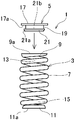
図1は、本発明実施例1に係るコイルばね組立体のコイルばね及びコイルばね用シートを分解して示す側面図である。[Coil spring]
1 is an exploded side view showing a coil spring and a coil spring sheet of a coil spring assembly according to
図1のコイルばね組立体1は、例えば自動車用ミッションダンパーや、自動車用足回りのリバウンドスプリング等に供される。 The
このコイルばね組立体1は、コイルばね3とコイルばね用シート5とからなっている。 The
コイルばね3は、その材質は特に限定されるものではないが、例えば、ばね用シリコンクロム鋼オイルテンパー線(SWOSC)の高強度材で形成され、本体部7の両端に相対的に縮径し一巻目まで形成され座巻部9、11を備えている。本体部7及び座巻部9、11の間に、座巻部9、11から本体部7へ漸次拡径する遷移部13、15を有している。 The material of the
このコイルばね3は、窒化処理により深さ50μmの表層と表面から3μm以下、好ましくは1.5μm程度の白層とを備えている。コイルばね3の白層の硬さは、750Hv以上に設定されている。かかる表層、白層、硬さの設定により、座巻部9、11にコイルばね用シート5を圧入するとき、破壊しないように靭性を与えることができる。 The
座巻部9、11の座面研磨は、周方向で180°以上、例えば先端から通常270°(3/4巻き)の範囲で行われ、座面9a、11aを形成している。従って、後述するコイルばね用シート5の受け面に安定して当接し、着座することができる。 The seat surface polishing of the
コイルばね用シート5は、その材質は特に限定されるものではないが、鉄系材料に浸炭窒化焼入れ焼き戻しが施されたものであり、例えば、機械構造用炭素鋼(S45C、S60C、その他)、ヘッダ(冷間圧造用)炭素鋼(SWCH)などで形成されている。 The material of the
このコイルばね用シート5は、例えば一対備えられ、両座巻部9、11に取付けられる。なお、図1では、座巻部9側のコイルばね用シート5のみを示して説明する。座巻部11側のコイルばね用シートの取り付け構造は、座巻部9側と同様であり、説明は省略する。 A pair of the
コイルばね用シート5は、座部17と、取付軸部19と、拡径部21とを有している。 The
座部17は、周回形状に形成され、受け面17aを有している。座部17の外径は、座巻部9の外径と同一又は僅かに大きく若しくは小さく形成される。これにより、座部17を座巻部9に安定して当接させることができる。 The
取付軸部19は、座部17の受け面17aから同心に突出形成され、この取付軸部19の先端に拡径部21が圧入ガイド用として形成されている。拡径部21の外径は、座巻部9の内径よりも大きく、圧入代を有している。拡径部21の先端外周には、圧入ガイド用の面取り21aが形成されている。 The mounting
取付軸部19は、座巻部9が嵌合して座巻部9の座面9aが座部17の受け面17aに当接した自由状態でコイルばね用シート5の拡径部21との間に隙間を有するか又は隙間が零となる軸長に設定されている。 The
取付軸部19への座巻部9の嵌合は、コイルばね3の一巻目で形成される座巻部9が取付軸部19の全周に周回で行われる。 The
座巻部9と拡径部21との間の隙間は、座巻部9が拡径部21に接触しない程度であれば良く、不必要に空ける必要はない。隙間が零の状態は、座巻部9が拡径部21に接触はするが座巻部9に応力が作用しない状態を言う。 The clearance between the
遷移部13は、座巻部9の座面9aが座部17の受け面17aに当接した状態で拡径部21を迂回し、遷移部13が拡径部21に接触しないように設定されている。 The
この迂回は、遷移部13が座巻部9から本体部7へ渦巻きを漸次拡大するようにして行われる。この迂回により座巻部9が取付軸部19の径方向へ相対移動しても遷移部13は拡径部21に接触しないか、隙間が零になる状態となる。
[圧入代範囲及びクラック]
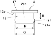
図2は、コイルばね用シートの拡大側面図、図3は、コイルばね用シートの各部の寸法を示す図表である。This detour is performed such that the
[Press-fit allowance range and cracks]
FIG. 2 is an enlarged side view of the coil spring sheet, and FIG. 3 is a chart showing dimensions of each part of the coil spring sheet.
図2のようにコイルばね用シート5の取付軸部19の軸長をB寸法、取付軸部19の直径をH寸法、拡径部21の直径をG寸法とする。 As shown in FIG. 2, the axial length of the mounting
図2、図3のように、実施例のG寸法は、比較例3種に比べて大きくしてある。このG寸法を大きくすることで、圧入代が大きくなる。G寸法は、座巻部9の内径が寸法公差を見込んだ最大のときよりも大きい値を設定している。圧入代を大きくすることで座巻部9に対するコイルばね用シート5の脱落を防ぐことができる。なお、比較例3種は、一般的なコイルばね用シートの寸法割合を示すものである。 As shown in FIGS. 2 and 3, the G dimension of the example is larger than that of the third comparative example. Increasing the G dimension increases the press-fitting allowance. The G dimension is set to a larger value than when the inner diameter of the
本発明実施例のコイルばね 3は、窒化処理を行った比較例のコイルばねに対し、圧入代が大きくなっても材質に関係なく座巻部9の破壊が抑制される窒化処理 となっている。 The
つまり、本発明実施例では、窒化処理により上記のように深さ50μmの表層と表面から3μm以下、好ましくは1.5μm程度の白層とを形成した。コイルばね3の白層の硬さは、前記のように750Hv以上に設定されている。このため、高い表面硬さと白層の柔らかさとを実現させ、靭性の高いコイルばね3を得ることができた。 That is, in the embodiment of the present invention, a surface layer having a depth of 50 μm and a white layer having a depth of 3 μm or less, preferably about 1.5 μm, were formed from the surface by nitriding as described above. The hardness of the white layer of the
これに対し、比較例は窒化処理により80〜120μmの表層と2.5〜5μmの白層とが形成されたものであり、硬さはあるが靱性が低く、本発明実施例のように圧入代が大きくなると座巻部が破壊される欠点がある。 On the other hand, in the comparative example, a surface layer of 80 to 120 μm and a white layer of 2.5 to 5 μm were formed by nitriding treatment, and the hardness was low but the toughness was low. There is a drawback that the end winding part is destroyed when the allowance increases.
図4は、本発明実施例及び比較例3種を示し、(A)は、コイルばねの表面から内部に至る硬さの変化を示すグラフ、(B)は、コイルばねの表面側の硬さの変化を示すグラフである。図4の縦軸はビッカース硬さ(Hv)を示し、横軸は表面からの深さ(mm)を示す。 FIG. 4 shows an embodiment of the present invention and three types of comparative examples, (A) is a graph showing the change in hardness from the surface of the coil spring to the inside, and (B) is the hardness on the surface side of the coil spring. It is a graph which shows the change of. The vertical axis in FIG. 4 indicates the Vickers hardness (Hv), and the horizontal axis indicates the depth (mm) from the surface.
図4のように、本発明実施例のコイルばね3は、表面から50μmの深さにおいて600Hvを僅かに上回る程度の硬さとなっているのに対し、比較例3種のコイルばねは、表面から60μmの深さにおいても600Hvを上回る硬さとなっている。 As shown in FIG. 4, the
このように、本発明実施例のコイルばね3は、比較例3種に対し、硬さ及び靭性において全く異なる設定とした。この設定により比較例に対し高い表面硬さと白層の柔らかさとを実現させ、靭性の高いコイルばね3となった。 Thus, the
図5(A)は、せん断応力に対するクラックの発生を示す説明図、(B)は、(A)のクラック発生数の指標を示す説明図である。コイルばねの有効部をリング状に切断し、図中白抜き矢印のように両側から引っ張り、クラックの発生を確認した。図5の縦軸は、曲げ応力(σMPa)を示す。 FIG. 5A is an explanatory diagram showing the occurrence of cracks with respect to shear stress, and FIG. 5B is an explanatory diagram showing an index of the number of cracks generated in (A). The effective part of the coil spring was cut into a ring shape and pulled from both sides as indicated by the white arrow in the figure, and the occurrence of cracks was confirmed. The vertical axis | shaft of FIG. 5 shows bending stress ((sigma) MPa).
クラックの発生を3ケ、2ケ、1ケ、無の4種類とし、曲げ応力との対応を見た。 There were four types of cracks, three, two, one, and none, and the correspondence with bending stress was observed.
図5のように、本実施例では、曲げ応力σ=1800MPaまでクラックの発生は無く、2000MPaで2ケ、2200MPaで1ケ、2400MPaで3ケのクラックが発生する結果を得た。 As shown in FIG. 5, in this example, no crack was generated up to bending stress σ = 1800 MPa, and 2 cracks were generated at 2000 MPa, 1 crack was generated at 2200 MPa, and 3 cracks were generated at 2400 MPa.
比較例1、2、3は、何れもσ=1800MPaで3ケのクラックが発生する結果となった。 In Comparative Examples 1, 2, and 3, all three cracks were generated at σ = 1800 MPa.
この結果より、本発明実施例は、比較例よりも圧入代範囲を大きくすることができることが分かる。 From this result, it can be seen that the embodiment of the present invention can make the press-fitting allowance range larger than that of the comparative example.
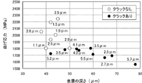
図6は、白層及び表層との関係における曲げ応力に対するクラックの発生を示す説明図である。図6の縦軸は曲げ応力(MPa)、横軸は、表層の深さ(μm)を示す。この場合、図5の場合と同様にして引っ張り、クラックの発生を確認した。 FIG. 6 is an explanatory diagram showing generation of cracks with respect to bending stress in the relationship between the white layer and the surface layer. The vertical axis in FIG. 6 indicates the bending stress (MPa), and the horizontal axis indicates the depth (μm) of the surface layer. In this case, the occurrence of cracks was confirmed in the same manner as in FIG.
図6のように、表層50μm、白層略3.0μm以下において、σ=1800MPa以上でも○で示すようにクラックの発生は無かった。この表層50μm、白層略3.0μm以下の構成により、コイルばね3の材質に関わらずクラックの発生を防止できる。 As shown in FIG. 6, when the surface layer was 50 μm and the white layer was approximately 3.0 μm or less, no crack was generated as indicated by ◯ even when σ = 1800 MPa or more. With this configuration of the surface layer of 50 μm and the white layer of approximately 3.0 μm or less, the occurrence of cracks can be prevented regardless of the material of the
これに対し、表層50μm以下であっても、白層3.5μm、白層5.2μmでは、σ=1800MPaを下回る範囲でもクラックが発生した。 On the other hand, even when the surface layer was 50 μm or less, cracks occurred in the white layer of 3.5 μm and the white layer of 5.2 μm even in the range of σ = 1800 MPa.
さらに、白層50μmを上回る範囲では、白層2.5〜5.7μmの何れにおいてもσ=1800MPa以下においてクラックが発生した。 Furthermore, in the range exceeding the
かかる結果からも明らかなように、深さ50μmの表層と表面から3μm以下の白層との組み合わせにより、高い表面硬さでありながらクラックが容易には発生しない靭性の高いコイルばね3を得ることができた。 As is apparent from the results, a high
このような本発明実施例の従来にないコイルばね3の特性により圧入代範囲を大きくすることができた。 The press-fitting allowance range could be increased due to the characteristics of the
図7は、圧入代範囲を示すグラフである。横軸はコイルばねの内径、縦軸は圧入代を示す。図7の線分Uは最大圧入代を示し、コイルばねが破壊しない限界であり、線分Lは最小圧入代を示し、使用時にコイルばねからコイルばね用シートが抜け落ちない限界である。 FIG. 7 is a graph showing the press-fitting allowance range. The horizontal axis represents the inner diameter of the coil spring, and the vertical axis represents the press-fitting allowance. The line segment U in FIG. 7 indicates the maximum press-fitting allowance and is a limit that the coil spring does not break, and the line segment L indicates the minimum press-fit allowance and is a limit that the coil spring sheet does not fall out of the coil spring during use.
図7のように、比較例では圧入時の破壊を考慮しコイルばねの内径に応じa、b、cの3種の圧入代範囲から選択する。3種類a、b、cから選択するのは、比較例のコイルばねは相対的に靭性が低く、内径に対する変形代が小さいからである。比較例では、この圧入代範囲の選択においてもコイルばねに対するコイルばね用シートの抜けがみられた。 As shown in FIG. 7, in the comparative example, in consideration of breakage during press-fitting, selection is made from three press-fitting allowance ranges of a, b, and c according to the inner diameter of the coil spring. The reason why the three types a, b, and c are selected is that the coil spring of the comparative example has relatively low toughness and a small deformation allowance with respect to the inner diameter. In the comparative example, the coil spring sheet was removed from the coil spring even in the selection of the press-fitting allowance range.
これに対し本実施例のコイルばね3は、比較例よりもはるかに高い靭性を有し、圧入代範囲を広げることができ、dにすることができた。この圧入代範囲dは、コイルばね3の内径に係わらず比較例3種の圧入代範囲a、b、cをすべて包含することができた。しかも、本実施例の圧入代範囲dでは、コイルばね3に対するコイルばね用シート5の抜けはなかった。 On the other hand, the
[適正な取り付け]
図2、図3に戻り、本実施例のコイルばね用シート5のH寸法は、比較例に比べ、小さく設定されている。座巻部9の内径が寸法公差を見込んだ最小のときより小さくすることで、コイルばね3との干渉を防ぎ、座巻部9が応力緩和する寸法となっている。[Proper installation]
Returning to FIGS. 2 and 3, the H dimension of the
B寸法は、比較例に比べ、大きくなっている。この寸法は、コイルばね3の1巻目が拡径部21に当たらないように設定されるものである。 The dimension B is larger than that of the comparative example. This dimension is set so that the first volume of the
つまり、本発明実施例のコイルばね用シート 5は、コイルばねの素線の直径を22mm、コイル座巻外径16.90mm、コイル座巻内径11.65mmとしたとき、B寸法において比較例1.60mmに対し2.49mmと長く設定されている。 That is, the
かかるB寸法の設定により、座巻部9へのコイルばね用シート5の取り付けは、図8のようになる。図9は、比較例に係る。 By setting the dimension B, the
図8は、本実施例のコイルばね用シートの取り付けを示し、(A)は、要部断面図、(B)は、要部拡大断面図、図9は、比較例のコイルばね用シートの取り付けを示し、(A)は、要部断面図、(B)は、要部拡大断面図である。 8A and 8B show the attachment of the coil spring sheet of this embodiment, where FIG. 9A is a cross-sectional view of the main part, FIG. 8B is an enlarged cross-sectional view of the main part, and FIG. The attachment is shown, (A) is a cross-sectional view of the main part, (B) is an enlarged cross-sectional view of the main part.
前記図3の本実施例及び比較例のコイルばね用シートの各部の寸法において、取付軸部の軸長Bの相違により、図8、図9の干渉の有無となる。 In the dimensions of the coil spring seats of the present embodiment and the comparative example of FIG. 3, the presence or absence of interference in FIGS. 8 and 9 depends on the difference in the axial length B of the mounting shaft portion.
図8のように、本発明実施例では、取付軸部19に座巻部9が嵌合して座巻部9の座面9aが座部17の受け面17aに当接し座巻部9の自由長状態で、先端9b上に位置する素線一巻目9cが、拡径部21に対して隙間を有している。 As shown in FIG. 8, in the embodiment of the present invention, the
この隙間を有したまま遷移部13がコイル径を漸次拡大するように遷移しながら拡径部21を迂回して接触せず、遷移部13でのさらなる半巻目13aの位置で拡径部21の外周側に隙間を持ってオフセットし、本体部7へと遷移する。実施例では二巻目に至る前にコイルばね用シート5の軸方向外に至る。 While the
したがって、図8の本発明実施例では、コイルばね用シート5のB寸法(図2)が大きく、座巻部9及び遷移部13が拡径部21に干渉しない。このため、コイルばね組立体1の耐久性を維持することができると共に、座巻部9の座面9aとコイルばね用シート5の受け面17aとの間の隙間を抑制し、取り付けを安定させることができる。 Therefore, in the embodiment of the present invention in FIG. 8, the B dimension (FIG. 2) of the
これに対し、図9の比較例は、コイルばね用シート5AのB寸法(図2)が相対的に小さく、座巻部9の座面9aが座部17の受け面17aに当接した状態で、コイルばね3の先端9b上に位置する素線一巻目9cが、拡径部21に干渉する。断面により図には表れないが、二巻目に至る遷移部も拡径部21に干渉する形態となる。なお、図9では、干渉部を重ねて図示している。 On the other hand, in the comparative example of FIG. 9, the B dimension (FIG. 2) of the
このような比較例の構造は、コイルばね3の座巻部9とコイルばね用シート5Aとの無理な干渉を招き、耐久性が損なわれると共に、座巻部9の座面9aとコイルばね用シート5Aの受け面17aとの間に大きな隙間ができ、取り付けが不安定になる。 Such a structure of the comparative example causes unreasonable interference between the
図10、図11は実施例2のコイルばね用シートの取り付けに係り、(A)は、要部断面図、(B)は、(A)のXB部、XIB部拡大断面図である。 10 and 11 relate to the attachment of the coil spring sheet of Example 2, (A) is a cross-sectional view of the main part, and (B) is an enlarged cross-sectional view of the XB part and XIB part of (A).
図10、図11のように、本実施例のコイルばね3Aは、断面円形の素線ではなく、断面オーバル形状の素線を用いた。コイルばね3Aは、素線のコイル内径側3Aaの断面が例えば半楕円形状部で構成され、コイル外径側3Abの断面が半円形状部で構成されている。 As shown in FIGS. 10 and 11, the
図10の例は、コイル外径側3Abの半円形状部の曲率半径を、実施例1の円形断面と同一にしたとき、座巻部9A(11A)とコイルばね用シート5の拡径部21との間の隙間が実施例1に比較して大きくなることを示している。 In the example of FIG. 10, when the radius of curvature of the semicircular part on the coil outer diameter side 3Ab is made the same as that of the circular cross section of Example 1, the
したがって、本実施例の場合、コイルばね用シート5のB寸法(図2)を小さくして図11のように座巻部9A(11A)とコイルばね用シート5の拡径部21との間の隙間の縮小を図ることができる。 Therefore, in the case of the present embodiment, the B dimension (FIG. 2) of the
その他、実施例1と同様の作用効果を奏することができる。 In addition, the same effects as those of the first embodiment can be achieved.
3、3A コイルばね
3Aa コイル内径側
3Ab コイル外径側
5、5A コイルばね用シート
7 本体部
9、9A、11、11A 座巻部
9a、9Aa、11a、11Aa 座面
13、15 遷移部
17 座部
17a 受け面
19、19A 取付軸部
21 拡径部3, 3A Coil spring 3Aa Coil inner diameter side 3Ab Coil
Claims (4)
前記コイルばねは、前記座巻部が前記本体部に対し相対的に縮径して一巻目まで形成され、前記本体部及び座巻部の間に前記座巻部から本体部へ渦巻きを漸次拡径する遷移部を有し、
前記コイルばね用シートは、前記座巻部の座面に受け面が当接する座部と、この座部の受け面から突出された取付軸部と、この取付軸部の先端に形成された圧入ガイド用の拡径部とを有し、
前記取付軸部は、前記座巻部が嵌合して該座巻部の座面が前記座部の受け面に当接した自由状態で前記コイルばね用シートの拡径部との間に隙間を有するか又は隙間が零となる軸長に設定され、
前記遷移部は、前記座巻部の座面が前記座部の受け面に当接した状態で前記拡径部を迂回し、拡径部に接触しないか、隙間が零になる、
ことを特徴とするコイルばね組立体。 A coil spring assembly comprising a coil spring provided with end winding portions at both ends of a main body portion and a coil spring seat attached to the end winding portion,
The coil spring is formed to the first volume by reducing the diameter of the end winding relative to the main body, and gradually spirals from the end winding to the main body between the main body and the end winding. It has a transition part that expands,
The coil spring sheet includes a seat portion with a receiving surface abutting against the seat surface of the end winding portion, a mounting shaft portion protruding from the receiving surface of the seat portion, and a press fit formed at the tip of the mounting shaft portion. An enlarged diameter portion for a guide,
The mounting shaft portion has a gap between the end portion of the coil spring seat in a free state in which the end portion is fitted and the seat surface of the end portion is in contact with the receiving surface of the seat portion. Or set to an axial length where the gap is zero,
The transition portion bypasses the enlarged diameter portion in a state in which the seat surface of the end turn portion is in contact with the receiving surface of the seat portion, or does not contact the enlarged diameter portion, or the gap becomes zero.
And a coil spring assembly.
前記コイルばねは、深さ50μm以下の表層硬化層と表面から3μm以下の白層とを備えた、
ことを特徴とするコイルばね組立体 The coil spring assembly according to claim 1,
The coil spring comprises a surface hardened layer having a depth of 50 μm or less and a white layer having a thickness of 3 μm or less from the surface.
Coil spring assembly characterized in that
前記コイルばねは、前記白層の硬さが750Hv以上である、
ことを特徴とするコイルばね組立体。The coil spring assembly according to claim 2,
The coil spring has a white layer hardness of 750 Hv or more,
And a coil spring assembly.
前記コイルばねの素線は、断面オーバル形状であり、コイル外径側が前記素線の断面半円形状部で構成された、
ことを特徴とするコイルばね組立体。The coil spring assembly according to any one of claims 1 to 3,
The element wire of the coil spring has an oval cross section, and the outer diameter side of the coil is configured by a semicircular section of the element wire.
And a coil spring assembly.
Applications Claiming Priority (3)
| Application Number | Priority Date | Filing Date | Title |
|---|---|---|---|
| JP2014126594 | 2014-06-19 | ||
| JP2014126594 | 2014-06-19 | ||
| PCT/JP2015/003092 WO2015194192A1 (en) | 2014-06-19 | 2015-06-19 | Coiled spring assembly |
Publications (2)
| Publication Number | Publication Date |
|---|---|
| JPWO2015194192A1 JPWO2015194192A1 (en) | 2017-04-20 |
| JP6499648B2 true JP6499648B2 (en) | 2019-04-10 |
Family
ID=54935194
Family Applications (1)
| Application Number | Title | Priority Date | Filing Date |
|---|---|---|---|
| JP2016529068A Active JP6499648B2 (en) | 2014-06-19 | 2015-06-19 | Coil spring assembly |
Country Status (6)
| Country | Link |
|---|---|
| US (1) | US20170152907A1 (en) |
| EP (1) | EP3159572B1 (en) |
| JP (1) | JP6499648B2 (en) |
| CN (1) | CN106489042B (en) |
| MX (1) | MX2016016937A (en) |
| WO (1) | WO2015194192A1 (en) |
Families Citing this family (9)
| Publication number | Priority date | Publication date | Assignee | Title |
|---|---|---|---|---|
| JP2019522756A (en) * | 2016-07-11 | 2019-08-15 | シェフラー テクノロジーズ アー・ゲー ウント コー. カー・ゲーSchaeffler Technologies AG & Co. KG | Spring end cap with improved retention |
| FR3065493B1 (en) * | 2017-04-25 | 2019-04-12 | Delphi Technologies Ip Limited | FUEL INJECTOR |
| JP2019002893A (en) * | 2017-06-20 | 2019-01-10 | 矢崎総業株式会社 | Temperature sensor |
| CN107476956A (en) * | 2017-07-28 | 2017-12-15 | 襄阳泽东化工集团有限公司 | The Compressor Valve of anti-spring breakage and the method for air trap spring breakage |
| DE102017123619B4 (en) * | 2017-10-11 | 2020-01-30 | Vibracoustic Gmbh | bending spring |
| CN111491847B (en) * | 2018-01-19 | 2022-09-13 | 奥托立夫开发公司 | Steering wheel |
| JP6802412B2 (en) * | 2018-03-29 | 2020-12-16 | 日本発條株式会社 | Coil spring assembly |
| CN110391536A (en) * | 2018-04-16 | 2019-10-29 | 青米(北京)科技有限公司 | A kind of installation method of protective door, socket and protective door |
| JP7182377B2 (en) * | 2018-05-16 | 2022-12-02 | サンコール株式会社 | coil spring |
Family Cites Families (12)
| Publication number | Priority date | Publication date | Assignee | Title |
|---|---|---|---|---|
| US3901494A (en) * | 1973-10-29 | 1975-08-26 | Ernest H Sena | Auxiliary vehicle spring installation |
| JPS60121333A (en) * | 1983-12-01 | 1985-06-28 | Murata Hatsujo Kk | Helical spring |
| JP2682645B2 (en) * | 1987-07-10 | 1997-11-26 | 株式会社杉田製線 | Oil tempered hard drawn steel wire spring and method for manufacturing the same |
| KR920001611B1 (en) * | 1987-07-10 | 1992-02-20 | 가부시끼가이샤 스기타 세이센 고오죠오 | Process for producing oil quench hardening and tempering and hard drawn steel wire of shaped section |
| JP3384814B2 (en) * | 1991-10-30 | 2003-03-10 | 株式会社東郷製作所 | Spring assembly |
| DE69224457T2 (en) * | 1991-10-30 | 1998-06-25 | Togo Seisakusho Kk | Spring assembly, in particular for automatic transmission of a vehicle |
| US6481702B1 (en) * | 2000-09-20 | 2002-11-19 | Meritor Heavy Vehicle Systems, Llc | Reduction of coil spring load height variability |
| SG157949A1 (en) * | 2004-07-28 | 2010-01-29 | Panasonic Refrigeration Device | System for reducing compressor noise and suspension spring and snubber arrangement therefor |
| JP4152364B2 (en) * | 2004-08-26 | 2008-09-17 | 株式会社東郷製作所 | High strength coil spring and manufacturing method thereof |
| JP4584774B2 (en) * | 2005-06-01 | 2010-11-24 | スワロー電機株式会社 | Terminal block and transformer equipped with this terminal block |
| JP2007064345A (en) * | 2005-08-31 | 2007-03-15 | Suncall Corp | Damper spring |
| JP4699273B2 (en) * | 2006-04-27 | 2011-06-08 | 株式会社東郷製作所 | Spring seat member and spring assembly |
-
2015
- 2015-06-19 JP JP2016529068A patent/JP6499648B2/en active Active
- 2015-06-19 US US15/320,187 patent/US20170152907A1/en not_active Abandoned
- 2015-06-19 MX MX2016016937A patent/MX2016016937A/en unknown
- 2015-06-19 WO PCT/JP2015/003092 patent/WO2015194192A1/en active Application Filing
- 2015-06-19 EP EP15808893.0A patent/EP3159572B1/en active Active
- 2015-06-19 CN CN201580031390.1A patent/CN106489042B/en active Active
Also Published As
| Publication number | Publication date |
|---|---|
| CN106489042B (en) | 2019-11-26 |
| EP3159572B1 (en) | 2020-06-03 |
| CN106489042A (en) | 2017-03-08 |
| EP3159572A1 (en) | 2017-04-26 |
| WO2015194192A1 (en) | 2015-12-23 |
| US20170152907A1 (en) | 2017-06-01 |
| EP3159572A4 (en) | 2018-04-04 |
| MX2016016937A (en) | 2017-04-27 |
| JPWO2015194192A1 (en) | 2017-04-20 |
Similar Documents
| Publication | Publication Date | Title |
|---|---|---|
| JP6499648B2 (en) | Coil spring assembly | |
| JP5100377B2 (en) | Coil spring | |
| US8297603B2 (en) | Spring retainer and spring system | |
| JP2021028542A (en) | Coil spring assembly | |
| EP3155293B1 (en) | Torsional vibration damper | |
| JP2005282701A (en) | Vibration absorbing rubber bush and its manufacturing method | |
| JP4748145B2 (en) | Roller bearing cage and roller bearing | |
| JP2008249035A (en) | Vibration control device and resin outer cylinder member to be used for the same | |
| JP4026609B2 (en) | Cylindrical dynamic damper | |
| JP5429394B2 (en) | Outer ring for shell type radial needle bearing and manufacturing method thereof | |
| JP4467503B2 (en) | Torque limiter | |
| JP4622250B2 (en) | Bearing device | |
| JP7165091B2 (en) | anti-vibration bush | |
| US20090142013A1 (en) | Bearing apparatus | |
| JP2008249020A (en) | One-way clutch and its manufacturing method | |
| DE102016221156A1 (en) | Dual mass flywheel and sliding bearing for this | |
| JP4609225B2 (en) | Valve operating device for internal combustion engine | |
| JP4569819B2 (en) | Rolling bearing | |
| JP2020008145A (en) | Torsional damper | |
| JP4558530B2 (en) | Torque limiter | |
| JP2018135935A (en) | Bush including inter-ring | |
| JP2020067127A (en) | Gear damper | |
| WO2015111687A4 (en) | Spring assembly for master cylinder | |
| JP2017110531A (en) | Engine valve | |
| JP2008267540A (en) | Bidirectional clutch shell outer ring, bidirectional clutch, rotation preventing structure for bidirectional clutch shell outer ring, and bidirectional clutch shell outer ring manufacturing method |
Legal Events
| Date | Code | Title | Description |
|---|---|---|---|
| A521 | Request for written amendment filed |
Free format text: JAPANESE INTERMEDIATE CODE: A523 Effective date: 20180207 |
|
| A621 | Written request for application examination |
Free format text: JAPANESE INTERMEDIATE CODE: A621 Effective date: 20180207 |
|
| A131 | Notification of reasons for refusal |
Free format text: JAPANESE INTERMEDIATE CODE: A131 Effective date: 20181204 |
|
| A521 | Request for written amendment filed |
Free format text: JAPANESE INTERMEDIATE CODE: A523 Effective date: 20190204 |
|
| TRDD | Decision of grant or rejection written | ||
| A01 | Written decision to grant a patent or to grant a registration (utility model) |
Free format text: JAPANESE INTERMEDIATE CODE: A01 Effective date: 20190305 |
|
| A61 | First payment of annual fees (during grant procedure) |
Free format text: JAPANESE INTERMEDIATE CODE: A61 Effective date: 20190315 |
|
| R150 | Certificate of patent or registration of utility model |
Ref document number: 6499648 Country of ref document: JP Free format text: JAPANESE INTERMEDIATE CODE: R150 |
|
| R250 | Receipt of annual fees |
Free format text: JAPANESE INTERMEDIATE CODE: R250 |
|
| R250 | Receipt of annual fees |
Free format text: JAPANESE INTERMEDIATE CODE: R250 |
|
| R250 | Receipt of annual fees |
Free format text: JAPANESE INTERMEDIATE CODE: R250 |