JP7182377B2 - coil spring - Google Patents
coil spring Download PDFInfo
- Publication number
- JP7182377B2 JP7182377B2 JP2018094718A JP2018094718A JP7182377B2 JP 7182377 B2 JP7182377 B2 JP 7182377B2 JP 2018094718 A JP2018094718 A JP 2018094718A JP 2018094718 A JP2018094718 A JP 2018094718A JP 7182377 B2 JP7182377 B2 JP 7182377B2
- Authority
- JP
- Japan
- Prior art keywords
- axial direction
- turn
- end portion
- spring wire
- outer end
- Prior art date
- Legal status (The legal status is an assumption and is not a legal conclusion. Google has not performed a legal analysis and makes no representation as to the accuracy of the status listed.)
- Active
Links
Images


Classifications
-
- F—MECHANICAL ENGINEERING; LIGHTING; HEATING; WEAPONS; BLASTING
- F16—ENGINEERING ELEMENTS AND UNITS; GENERAL MEASURES FOR PRODUCING AND MAINTAINING EFFECTIVE FUNCTIONING OF MACHINES OR INSTALLATIONS; THERMAL INSULATION IN GENERAL
- F16F—SPRINGS; SHOCK-ABSORBERS; MEANS FOR DAMPING VIBRATION
- F16F1/00—Springs
- F16F1/02—Springs made of steel or other material having low internal friction; Wound, torsion, leaf, cup, ring or the like springs, the material of the spring not being relevant
- F16F1/04—Wound springs
- F16F1/047—Wound springs characterised by varying pitch
-
- F—MECHANICAL ENGINEERING; LIGHTING; HEATING; WEAPONS; BLASTING
- F16—ENGINEERING ELEMENTS AND UNITS; GENERAL MEASURES FOR PRODUCING AND MAINTAINING EFFECTIVE FUNCTIONING OF MACHINES OR INSTALLATIONS; THERMAL INSULATION IN GENERAL
- F16F—SPRINGS; SHOCK-ABSORBERS; MEANS FOR DAMPING VIBRATION
- F16F1/00—Springs
- F16F1/02—Springs made of steel or other material having low internal friction; Wound, torsion, leaf, cup, ring or the like springs, the material of the spring not being relevant
- F16F1/04—Wound springs
- F16F1/042—Wound springs characterised by the cross-section of the wire
-
- F—MECHANICAL ENGINEERING; LIGHTING; HEATING; WEAPONS; BLASTING
- F16—ENGINEERING ELEMENTS AND UNITS; GENERAL MEASURES FOR PRODUCING AND MAINTAINING EFFECTIVE FUNCTIONING OF MACHINES OR INSTALLATIONS; THERMAL INSULATION IN GENERAL
- F16F—SPRINGS; SHOCK-ABSORBERS; MEANS FOR DAMPING VIBRATION
- F16F1/00—Springs
- F16F1/02—Springs made of steel or other material having low internal friction; Wound, torsion, leaf, cup, ring or the like springs, the material of the spring not being relevant
- F16F1/04—Wound springs
- F16F1/06—Wound springs with turns lying in cylindrical surfaces
-
- F—MECHANICAL ENGINEERING; LIGHTING; HEATING; WEAPONS; BLASTING
- F01—MACHINES OR ENGINES IN GENERAL; ENGINE PLANTS IN GENERAL; STEAM ENGINES
- F01L—CYCLICALLY OPERATING VALVES FOR MACHINES OR ENGINES
- F01L1/00—Valve-gear or valve arrangements, e.g. lift-valve gear
- F01L1/46—Component parts, details, or accessories, not provided for in preceding subgroups
- F01L1/462—Valve return spring arrangements
-
- F—MECHANICAL ENGINEERING; LIGHTING; HEATING; WEAPONS; BLASTING
- F01—MACHINES OR ENGINES IN GENERAL; ENGINE PLANTS IN GENERAL; STEAM ENGINES
- F01L—CYCLICALLY OPERATING VALVES FOR MACHINES OR ENGINES
- F01L2303/00—Manufacturing of components used in valve arrangements
- F01L2303/01—Tools for producing, mounting or adjusting, e.g. some part of the distribution
-
- F—MECHANICAL ENGINEERING; LIGHTING; HEATING; WEAPONS; BLASTING
- F01—MACHINES OR ENGINES IN GENERAL; ENGINE PLANTS IN GENERAL; STEAM ENGINES
- F01L—CYCLICALLY OPERATING VALVES FOR MACHINES OR ENGINES
- F01L2820/00—Details on specific features characterising valve gear arrangements
- F01L2820/01—Absolute values
-
- F—MECHANICAL ENGINEERING; LIGHTING; HEATING; WEAPONS; BLASTING
- F01—MACHINES OR ENGINES IN GENERAL; ENGINE PLANTS IN GENERAL; STEAM ENGINES
- F01L—CYCLICALLY OPERATING VALVES FOR MACHINES OR ENGINES
- F01L2820/00—Details on specific features characterising valve gear arrangements
- F01L2820/02—Formulas
Description
本発明は、内燃機関の弁ばねや高圧ポンプ用ばね等に利用可能なコイルばねに関する。 The present invention relates to a coil spring that can be used as a valve spring for an internal combustion engine, a spring for a high-pressure pump, and the like.
ばね線材を軸線方向一方側から他方側へ延びる螺旋形状に成形してなるコイルばねは、内燃機関の弁ばねや高圧ポンプ用ばね等として、広く利用されている。 A coil spring formed by forming a spring wire into a helical shape extending from one side to the other in the axial direction is widely used as a valve spring for an internal combustion engine, a spring for a high-pressure pump, and the like.
前記コイルばねは、軸線方向に圧縮された際に軸線方向に沿った弾性力を発揮することを意図した部材であるが、圧縮時に、軸線方向に沿った弾性力に加えて、軸線方向とは直交する方向にも力(横力)を発生することが知られている。 The coil spring is a member intended to exhibit elastic force along the axial direction when compressed in the axial direction. It is known to generate forces (lateral forces) in orthogonal directions as well.
横力の発生は可能な限り防止することが望まれる。
即ち、例えば、前記コイルばねを往復動するプランジャーの押圧部材として用いた場合に横力が生じると、前記プランジャーと当該プランジャーが往復動可能に収容される案内面との間に生じる摩擦力が大きくなる。
前記摩擦力の増加は、前記プランジャーの摺動抵抗に起因する摩耗や摩擦熱の上昇を招き、前記プランジャーが用いられる高圧ポンプ等の装置に作動不具合を生じさせる恐れがある。
It is desirable to prevent the generation of lateral force as much as possible.
That is, for example, when the coil spring is used as a pressing member for a reciprocating plunger, when a lateral force is generated, friction occurs between the plunger and a guide surface on which the plunger is reciprocally accommodated. power increases.
The increase in the frictional force causes wear due to the sliding resistance of the plunger and an increase in frictional heat, which may cause malfunctions in devices such as high-pressure pumps in which the plunger is used.
この点に関し、本願出願人は、横力の低減を目的としたコイルばねを提案している(下記特許文献1及び2参照)。
In this regard, the applicant of the present application has proposed a coil spring for the purpose of reducing lateral force (see
前記特許文献1に記載のコイルばねは、セット高さから最大使用高さまでの間で有効巻数が整数となるように構成されており、有効巻数が整数又は整数近傍とはされていないコイルばねに比して、圧縮動作時に発生する横力を低減し得るようになっている。
The coil spring described in
前記特許文献2に記載のコイルばねは、軸線方向に隣接するばね線材間の線間隙間によって画される線間巻きが、軸線方向一方側において線間隙間がゼロとされた第1線間隙間ゼロ点から螺旋形状に沿って進むに従って線間隙間が大きくなる第1端部領域と、前記第1端部領域よりも軸線方向他方側に位置し、線間隙間が基準値のL(L>0)とされた基準領域と、前記基準領域より軸線方向他方側に位置し、軸線方向他方側へ螺旋形状に沿って進むに従って線間隙間が狭くなり、第2線間隙間ゼロ点において自然長状態での線間隙間がゼロとなる第2端部領域とを含み、前記第1及び第2端部領域は、線間巻き数が1を超え且つ終端位置における自然長状態での線間距離がLより大となり、さらに、前記線間巻きが、前記第1端部領域の終端位置と前記基準領域との間に設けられ、前記第1端部領域の終端位置から軸線方向他方側へ螺旋形状に沿って進むに従って線間距離が小さくなって基準値のLに到達する第1移行領域と、前記第2端部領域の終端位置と前記基準領域との間に設けられ、前記第2端部領域の終端位置から軸線方向一方側へ螺旋形状に沿って進むに従って線間距離が小さくなって基準値のLに到達する第2移行領域とを有するように、構成されている。
In the coil spring described in
前記特許文献2に記載のコイルばねは、第1及び第2端部領域での線間隙間が外端側から内端側へ行くに従ってゼロから徐々に大きくなって基準値Lに到達するように構成された従来のコイルばねに比して、圧縮動作時において前記第1及び第2端部領域に線間隙間ゼロが発生することを有効に抑えることができ、これにより、横力の発生を防止することができるようになっている。
In the coil spring described in
このように、前記特許文献1及び2に記載のコイルばねはそれぞれの前記構成によって横力の発生を有効に防止し得るものであるが、座面に関しては改善の余地があった。
As described above, the coil springs described in
即ち、コイルばねは、軸線方向一方側の第1座巻き部に第1座面を有し、軸線方向他方側の第2座巻き部に第2座面を有している。 That is, the coil spring has a first seat surface on the first end turn portion on one side in the axial direction, and a second seat surface on the second end turn portion on the other side in the axial direction.
前記第1座面は、コイルばねの軸線方向に対して直交する方向に延びるように前記第1座巻き部の軸線方向外表面を研磨することによって形成される。同様に、前記第2座面は、コイルばねの軸線方向に対して直交する方向に延びるように前記第2座巻き部の軸線方向外表面を研磨することによって形成される。 The first bearing surface is formed by grinding the axial outer surface of the first end turn portion so as to extend in a direction perpendicular to the axial direction of the coil spring. Similarly, the second bearing surface is formed by grinding the axial outer surface of the second end turn portion so as to extend in a direction orthogonal to the axial direction of the coil spring.
ここで、圧縮動作時に前記コイルばねの姿勢安定化を図って横力の発生を防止する為には、前記第1及び第2座面をそれぞれ軸線回りに少なくとも半周に亘って設けることが好ましい。 Here, in order to stabilize the posture of the coil spring during the compression operation and prevent the occurrence of lateral force, it is preferable to provide the first and second seating surfaces over at least half a circumference around the axis.
しかしながら、単に、前記第1及び第2座面の軸線回り長さを広げるとすると、前記コイルばねの第1及び第2座巻き部の端部での厚みが薄くなり、前記第1及び第2座巻き部の剛性が低下するおそれがある。 However, if the lengths around the axis of the first and second seat surfaces are simply increased, the thickness of the end portions of the first and second coil spring portions of the coil spring becomes thinner, and the first and second seat surfaces become thin. The rigidity of the end turn portion may decrease.
本発明は、斯かる従来技術に鑑みなされたものであり、座面の軸線回りの長大化を図りつつ、座巻き部の端部の剛性低下を有効に防止し得るコイルばねの提供を目的とする。 SUMMARY OF THE INVENTION It is an object of the present invention to provide a coil spring that can effectively prevent a decrease in rigidity at the end portion of the end turn portion while increasing the length of the seat surface around the axis. do.
前記目的を達成するために、本発明の第1態様は、軸線方向一方側の第1端部から軸線方向他方側の第2端部へ向かってばね線材が螺旋形状に成形されてなるコイルばねであって、軸線方向一方側を向く第1座面を有し、前記第1端部を形成する外端部から軸線方向他方側の内端部へ向かって周方向に沿って延びる第1座巻き部と、軸線方向他方側を向く第2座面を有し、前記第2端部を形成する外端部から軸線方向一方側の内端部へ向かって周方向に沿って延びる第2座巻き部と、前記第1座巻き部の内端部から軸線方向他方側へ向かって周方向に沿って螺旋状に延びて、前記第2座巻き部の内端部に連結される中央巻き部とを備え、前記中央巻き部の軸線方向一方側の端部及び前記第1座巻き部の外端部の間の線間隙間がゼロとなるように前記第1座巻き部の外端部から内端部までの間の軸線方向他方側への前記ばね線材の中心位置の変位量が前記ばね線材の厚みとされた上で、前記第1座巻き部の外端部から内端部へ向けて進むに従って前記ばね線材の中心位置が徐々に軸線方向他方側に位置されつつ、前記第1座巻き部の外端部と当該外端部から前記第1座巻き部の内端部へ向けて半周だけ進んだ地点との間の軸線方向他方側への前記ばね線材の中心位置の変位量は前記ばね線材の厚みの1/4よりも小とされ、且つ、前記第1座巻き部の外端部から内端部へ向けて周方向に沿って進む前記ばね線材の周方向移動量と前記第1座巻き部の外端部からの軸線方向他方側への前記ばね線材の中心位置の軸線方向変位量との関係が、前記座巻き部の外端部から内端部までの全域に亘って上方に開く曲線とされており、前記曲線は、当該曲線に対する接線の傾きが前記座巻き部の外端部から内端部へ進むに従って大きくなる形状とされているコイルばねを提供する。 In order to achieve the above object, a first aspect of the present invention provides a coil spring in which a spring wire is formed in a helical shape from a first end on one side in the axial direction toward a second end on the other side in the axial direction. The first seat has a first seat surface facing one side in the axial direction, and extends along the circumferential direction from the outer end portion forming the first end portion toward the inner end portion on the other side in the axial direction. A second seat having a winding portion and a second seat surface facing the other side in the axial direction, and extending along the circumferential direction from an outer end portion forming the second end portion toward an inner end portion on the one side in the axial direction. a winding portion, and a central winding portion spirally extending along the circumferential direction from the inner end portion of the first end turn portion toward the other side in the axial direction and connected to the inner end portion of the second end turn portion. and from the outer end of the first end turn so that the line gap between the end of the center turn on one side in the axial direction and the outer end of the first end turn is zero The amount of displacement of the center position of the spring wire toward the other side in the axial direction up to the inner end is defined as the thickness of the spring wire, and then the first end turn portion is shifted from the outer end to the inner end. As it advances, the center position of the spring wire is gradually positioned on the other side in the axial direction, and the outer end portion of the first end turn portion and the outer end portion toward the inner end portion of the first end turn portion The amount of displacement of the center position of the spring wire to the other side in the axial direction between the point advanced by half the circumference is smaller than 1/4 of the thickness of the spring wire, and the outer side of the first end turn portion A circumferential movement amount of the spring wire moving along the circumferential direction from the end portion toward the inner end portion and an axis line of the center position of the spring wire toward the other axial direction side from the outer end portion of the first end turn portion The relationship between the amount of directional displacement is a curve that opens upward over the entire area from the outer end to the inner end of the end turn portion. To provide a coil spring having a shape which becomes larger as it progresses from the outer end to the inner end of a coil spring.
前記目的を達成するために、本発明の第2様は、軸線方向一方側の第1端部から軸線方向他方側の第2端部へ向かってばね線材が螺旋形状に成形されてなるコイルばねであって、軸線方向一方側を向く第1座面を有し、前記第1端部を形成する外端部から軸線方向他方側の内端部へ向かって周方向に沿って延びる第1座巻き部と、軸線方向他方側を向く第2座面を有し、前記第2端部を形成する外端部から軸線方向一方側の内端部へ向かって周方向に沿って延びる第2座巻き部と、前記第1座巻き部の内端部から軸線方向他方側へ向かって周方向に沿って螺旋状に延びて、前記第2座巻き部の内端部に連結される中央巻き部とを備え、前記中央巻き部の軸線方向一方側の端部及び前記第1座巻き部の外端部の間の線間隙間がゼロとなるように前記第1座巻き部の外端部から内端部までの間の軸線方向他方側への前記ばね線材の中心位置の変位量が前記ばね線材の厚みとされた上で、前記第1座巻き部の外端部から内端部へ向けて進むに従って前記ばね線材の中心位置が徐々に軸線方向他方側に位置されつつ、前記第1座巻き部の外端部と当該外端部から前記第1座巻き部の内端部へ向けて半周だけ進んだ地点との間の軸線方向他方側への前記ばね線材の中心位置の変位量は前記ばね線材の厚みの1/4よりも小とされ、且つ、前記第1座巻き部の外端部から内端部へ向けて周方向に沿って進む前記ばね線材の周方向移動量と前記第1座巻き部の外端部からの軸線方向他方側への前記ばね線材の中心位置の軸線方向変位量との関係が上方に開く曲線状とされているコイルばねを提供する。 In order to achieve the above object, a second aspect of the present invention is a coil spring in which a spring wire is spirally formed from a first end on one side in the axial direction toward a second end on the other side in the axial direction. The first seat has a first seat surface facing one side in the axial direction, and extends along the circumferential direction from the outer end portion forming the first end portion toward the inner end portion on the other side in the axial direction. A second seat having a winding portion and a second seat surface facing the other side in the axial direction, and extending along the circumferential direction from an outer end portion forming the second end portion toward an inner end portion on the one side in the axial direction. a winding portion, and a central winding portion spirally extending along the circumferential direction from the inner end portion of the first end turn portion toward the other side in the axial direction and connected to the inner end portion of the second end turn portion. and from the outer end of the first end turn so that the line gap between the end of the center turn on one side in the axial direction and the outer end of the first end turn is zero The amount of displacement of the center position of the spring wire toward the other side in the axial direction up to the inner end is defined as the thickness of the spring wire, and then the first end turn portion is shifted from the outer end to the inner end. As it advances, the center position of the spring wire is gradually positioned on the other side in the axial direction, and the outer end portion of the first end turn portion and the outer end portion toward the inner end portion of the first end turn portion The amount of displacement of the center position of the spring wire to the other side in the axial direction between the point advanced by half the circumference is smaller than 1/4 of the thickness of the spring wire, and the outer side of the first end turn portion A circumferential movement amount of the spring wire moving along the circumferential direction from the end portion toward the inner end portion and an axis line of the center position of the spring wire toward the other axial direction side from the outer end portion of the first end turn portion To provide a coil spring having a curvilinear shape that opens upward in relation to a directional displacement amount.
本発明の第1~第2態様に係るコイルばねにおいては、軸線方向に隣接するばね線材間の線間隙間によって画される線間巻きが、前記中央巻き部の軸線方向一方側の端部及び前記第1座巻き部の外端部の間において線間隙間がゼロとされた第1線間隙間ゼロ点から軸線方向他方側へ周方向に沿って進むに従って線間隙間が大きくなる第1変化領域と、前記第1変化領域よりも軸線方向他方側に位置し、線間隙間が基準値のままで軸線方向他方側へ周方向に沿って延びる基準領域とを含み、前記第1変化領域は、軸線方向外端の前記第1線間隙間ゼロ点から軸線方向他方側へ向かって周方向に1巻き未満の位置で終焉し且つ軸線方向内端の終端での線間隙間が基準値よりも大きくなるように構成され、前記線間巻きには、前記第1変化領域及び前記基準領域の間に位置し、前記第1変化領域の終端から前記基準領域の軸線方向一方側の端部へ向かって周方向に進むに従って線間距離が小さくなって基準値となる第1移行領域が設けられる。 In the coil springs according to the first and second aspects of the present invention, the wire-to-wire windings defined by the wire-to-wire gaps between the axially adjacent spring wire rods are the one axial end of the central winding portion and the A first change in which the line gap increases as the line gap progresses along the circumferential direction from the first line gap zero point where the line gap is zero between the outer ends of the first end turn portion toward the other side in the axial direction. and a reference region located on the other side in the axial direction relative to the first changed region and extending along the circumferential direction toward the other side in the axial direction with the line-to-line gap remaining at the reference value, wherein the first changed region is , ends at a position of less than one turn in the circumferential direction from the zero point of the first inter-line gap at the axial outer end toward the other side in the axial direction, and the inter-line gap at the terminal end of the axial inner end is larger than the reference value. In the line-to-line winding, the winding is located between the first change area and the reference area, and extends from the terminal end of the first change area toward one end of the reference area in the axial direction. A first transition region is provided in which the line-to-line distance becomes smaller as it progresses in the circumferential direction and becomes a reference value.
前記目的を達成するために、本発明の第3態様は、軸線方向一方側の第1端部から軸線方向他方側の第2端部へ向かってばね線材が螺旋形状に成形されてなるコイルばねであって、軸線方向一方側を向く第1座面を有し、前記第1端部を形成する外端部から軸線方向他方側の内端部へ向かって周方向に沿って延びる第1座巻き部と、軸線方向他方側を向く第2座面を有し、前記第2端部を形成する外端部から軸線方向一方側の内端部へ向かって周方向に沿って延びる第2座巻き部と、前記第1座巻き部の内端部から軸線方向他方側へ向かって周方向に沿って螺旋状に延びて、前記第2座巻き部の内端部に連結される中央巻き部とを備え、前記中央巻き部の軸線方向一方側の端部及び前記第1座巻き部の外端部の間の線間隙間がゼロとなるように前記第1座巻き部の外端部から内端部までの間の軸線方向他方側への前記ばね線材の中心位置の変位量が前記ばね線材の厚みとされた上で、前記第1座巻き部の外端部から内端部へ向けて進むに従って前記ばね線材の中心位置が徐々に軸線方向他方側に位置されつつ、前記第1座巻き部の外端部と当該外端部から前記第1座巻き部の内端部へ向けて半周だけ進んだ地点との間の軸線方向他方側への前記ばね線材の中心位置の変位量は前記ばね線材の厚みの1/4よりも小とされ、且つ、前記第1座巻き部の外端部から内端部へ向けて周方向に沿って進む前記ばね線材の周方向移動量と前記第1座巻き部の外端部からの軸線方向他方側への前記ばね線材の中心位置の軸線方向変位量との関係が上方に開く曲線状とされ、前記中央巻き部の軸線方向他方側の端部及び前記第2座巻き部の外端部の間の線間隙間がゼロとなるように前記第2座巻き部の外端部から内端部までの間の軸線方向一方側への変位量が前記ばね線材の厚みとされた上で、前記第2座巻き部の外端部から内端部へ向けて進むに従って前記ばね線材の中心位置が徐々に軸線方向一方側に位置されつつ、前記第2座巻き部の外端部と当該外端部から前記第2座巻き部の内端部へ向けて半周だけ進んだ地点との間の軸線方向一方側への前記ばね線材の中心位置の変位量は前記ばね線材の厚みの1/4よりも小とされ、且つ、前記第2座巻き部の外端部から内端部へ向けて周方向に沿って進む前記ばね線材の周方向移動量と前記第2座巻き部の外端部からの軸線方向一方側への前記ばね線材の中心位置の軸線方向変位量との関係が、前記第2座巻き部の外端部から内端部までの全域に亘って下方に開く曲線とされており、前記曲線は、当該曲線に対する接線の傾きが前記第2座巻き部の外端部から内端部へ進むに従って大きくなる形状とされているコイルばねを提供する。 In order to achieve the above object, a third aspect of the present invention provides a coil spring in which a spring wire is formed in a helical shape from a first end on one side in the axial direction toward a second end on the other side in the axial direction. The first seat has a first seat surface facing one side in the axial direction, and extends along the circumferential direction from the outer end portion forming the first end portion toward the inner end portion on the other side in the axial direction. A second seat having a winding portion and a second seat surface facing the other side in the axial direction, and extending along the circumferential direction from an outer end portion forming the second end portion toward an inner end portion on the one side in the axial direction. a winding portion, and a central winding portion spirally extending along the circumferential direction from the inner end portion of the first end turn portion toward the other side in the axial direction and connected to the inner end portion of the second end turn portion. and from the outer end of the first end turn so that the line gap between the end of the center turn on one side in the axial direction and the outer end of the first end turn is zero The amount of displacement of the center position of the spring wire toward the other side in the axial direction up to the inner end is defined as the thickness of the spring wire, and then the first end turn portion is shifted from the outer end to the inner end. As it advances, the center position of the spring wire is gradually positioned on the other side in the axial direction, and the outer end portion of the first end turn portion and the outer end portion toward the inner end portion of the first end turn portion The amount of displacement of the center position of the spring wire to the other side in the axial direction between the point advanced by half the circumference is smaller than 1/4 of the thickness of the spring wire, and the outer side of the first end turn portion A circumferential movement amount of the spring wire moving along the circumferential direction from the end portion toward the inner end portion and an axis line of the center position of the spring wire toward the other axial direction side from the outer end portion of the first end turn portion The relationship with the amount of directional displacement is curved so that it opens upward, and the line gap between the end of the center winding portion on the other side in the axial direction and the outer end portion of the second end turn portion is zero. The amount of displacement to one side in the axial direction from the outer end to the inner end of the second end turn portion is defined as the thickness of the spring wire, and While the center position of the spring wire is gradually positioned on one side in the axial direction as it progresses toward the end portion, the outer end portion of the second end turn portion and the inner end of the second end turn portion from the outer end portion The amount of displacement of the center position of the spring wire toward the one side in the axial direction between the point half the circumference toward the second seat is set to be smaller than 1/4 of the thickness of the spring wire, and A circumferential movement amount of the spring wire moving along the circumferential direction from the outer end to the inner end of the winding portion, and a movement of the spring wire from the outer end of the second end turn portion to one side in the axial direction. Relationship with axial displacement of center position is a curve that opens downward over the entire area from the outer end to the inner end of the second end turn portion, and the curve is such that the slope of the tangent to the curve is that of the second end turn portion. To provide a coil spring having a shape that increases in size from an outer end to an inner end.
前記目的を達成するために、本発明の第4態様は、軸線方向一方側の第1端部から軸線方向他方側の第2端部へ向かってばね線材が螺旋形状に成形されてなるコイルばねであって、軸線方向一方側を向く第1座面を有し、前記第1端部を形成する外端部から軸線方向他方側の内端部へ向かって周方向に沿って延びる第1座巻き部と、軸線方向他方側を向く第2座面を有し、前記第2端部を形成する外端部から軸線方向一方側の内端部へ向かって周方向に沿って延びる第2座巻き部と、前記第1座巻き部の内端部から軸線方向他方側へ向かって周方向に沿って螺旋状に延びて、前記第2座巻き部の内端部に連結される中央巻き部とを備え、前記中央巻き部の軸線方向一方側の端部及び前記第1座巻き部の外端部の間の線間隙間がゼロとなるように前記第1座巻き部の外端部から内端部までの間の軸線方向他方側への前記ばね線材の中心位置の変位量が前記ばね線材の厚みとされた上で、前記第1座巻き部の外端部から内端部へ向けて進むに従って前記ばね線材の中心位置が徐々に軸線方向他方側に位置されつつ、前記第1座巻き部の外端部と当該外端部から前記第1座巻き部の内端部へ向けて半周だけ進んだ地点との間の軸線方向他方側への前記ばね線材の中心位置の変位量は前記ばね線材の厚みの1/4よりも小とされ、且つ、前記第1座巻き部の外端部から内端部へ向けて周方向に沿って進む前記ばね線材の周方向移動量と前記第1座巻き部の外端部からの軸線方向他方側への前記ばね線材の中心位置の軸線方向変位量との関係が上方に開く曲線状とされ、前記中央巻き部の軸線方向他方側の端部及び前記第2座巻き部の外端部の間の線間隙間がゼロとなるように前記第2座巻き部の外端部から内端部までの間の軸線方向一方側への前記ばね線材の中心位置の変位量が前記ばね線材の厚みとされた上で、前記第2座巻き部の外端部から内端部へ向けて進むに従って前記ばね線材の中心位置が徐々に軸線方向一方側に位置されつつ、前記第2座巻き部の外端部と当該外端部から前記第2座巻き部の内端部へ向けて半周だけ進んだ地点との間の軸線方向一方側への前記ばね線材の中心位置の変位量は前記ばね線材の厚みの1/4よりも小とされ、且つ、前記第2座巻き部の外端部から内端部へ向けて周方向に沿って進む前記ばね線材の周方向移動量と前記第2座巻き部の外端部からの軸線方向一方側への前記ばね線材の中心位置の軸線方向変位量との関係が下方に開く曲線状とされているコイルばねを提供する。 In order to achieve the above object, a fourth aspect of the present invention provides a coil spring in which a spring wire is formed in a helical shape from a first end on one side in the axial direction toward a second end on the other side in the axial direction. The first seat has a first seat surface facing one side in the axial direction, and extends along the circumferential direction from the outer end portion forming the first end portion toward the inner end portion on the other side in the axial direction. A second seat having a winding portion and a second seat surface facing the other side in the axial direction, and extending along the circumferential direction from an outer end portion forming the second end portion toward an inner end portion on the one side in the axial direction. a winding portion, and a central winding portion spirally extending along the circumferential direction from the inner end portion of the first end turn portion toward the other side in the axial direction and connected to the inner end portion of the second end turn portion. and from the outer end of the first end turn so that the line gap between the end of the center turn on one side in the axial direction and the outer end of the first end turn is zero The amount of displacement of the center position of the spring wire toward the other side in the axial direction up to the inner end is defined as the thickness of the spring wire, and then the first end turn portion is shifted from the outer end to the inner end. As it advances, the center position of the spring wire is gradually positioned on the other side in the axial direction, and the outer end portion of the first end turn portion and the outer end portion toward the inner end portion of the first end turn portion The amount of displacement of the center position of the spring wire to the other side in the axial direction between the point advanced by half the circumference is smaller than 1/4 of the thickness of the spring wire, and the outer side of the first end turn portion A circumferential movement amount of the spring wire moving along the circumferential direction from the end portion toward the inner end portion and an axis line of the center position of the spring wire toward the other axial direction side from the outer end portion of the first end turn portion The relationship with the amount of directional displacement is curved so that it opens upward, and the line gap between the end of the center winding portion on the other side in the axial direction and the outer end portion of the second end turn portion is zero. The amount of displacement of the center position of the spring wire to one side in the axial direction between the outer end portion and the inner end portion of the second end turn portion is defined as the thickness of the spring wire, and the second end turn As the spring wire advances from the outer end to the inner end of the portion, the center position of the spring wire is gradually positioned on one side in the axial direction, and the outer end of the second end turn portion and the second coil from the outer end. The amount of displacement of the center position of the spring wire toward one side in the axial direction between the point advanced halfway toward the inner end of the two end turns is set to be smaller than 1/4 of the thickness of the spring wire. and one of the amount of circumferential movement of the spring wire moving along the circumferential direction from the outer end portion of the second end turn portion toward the inner end portion and the axial direction direction from the outer end portion of the second end turn portion Center position of the spring wire to the side To provide a coil spring having a curved shape that opens downward in relation to the amount of axial displacement of a device.
本発明の第3~第4態様に係るコイルばねにおいては、軸線方向に隣接するばね線材間の線間隙間によって画される線間巻きは、前記中央巻き部の軸線方向一方側の端部及び前記第1座巻き部の外端部の間において線間隙間がゼロとされた第1線間隙間ゼロ点から軸線方向他方側へ周方向に沿って進むに従って線間隙間が大きくなる第1変化領域と、前記第1変化領域よりも軸線方向他方側に位置し、線間隙間が基準値のままで軸線方向他方側へ周方向に沿って延びる基準領域と、前記基準領域よりも軸線方向他方側に位置し、軸線方向他方側へ周方向に沿って進むに従って線間隙間が小さくなって線間隙間がゼロとされた第2線間隙間ゼロ点で終焉する第2変化領域とを含み、前記第1変化領域は、軸線方向外端の前記第1線間隙間ゼロ点から軸線方向他方側へ周方向に1巻き未満の位置で終焉し且つ軸線方向内端の終端での線間隙間が基準値よりも大きくなるように構成され、前記第2変化領域は、軸線方向外端の前記第2線間隙間ゼロ点から軸線方向一方側へ周方向に1巻き未満の位置で終焉し且つ軸線方向内端の終端での線間隙間が基準値よりも大きくなるように構成され、前記線間巻きには、前記第1変化領域及び前記基準領域の間に位置し、前記第1変化領域の終端から前記基準領域の軸線方向一方側の端部へ向かって周方向に進むに従って線間距離が小さくなって基準値となる第1移行領域と、前記第2変化領域及び前記基準領域の間に位置し、前記第2変化領域の終端から前記基準領域の軸線方向他方側の端部へ向かって周方向に進むに従って線間距離が小さくなって基準値となる第2移行領域とが設けられる。 In the coil springs according to the third and fourth aspects of the present invention, the wire-to-wire windings defined by the wire-to-wire gaps between the spring wires adjacent in the axial direction are the one end portion in the axial direction of the central winding portion and the A first change in which the line gap increases as the line gap progresses along the circumferential direction from the first line gap zero point where the line gap is zero between the outer ends of the first end turn portion toward the other side in the axial direction. a reference region located on the other side in the axial direction of the first change region and extending along the other side in the axial direction with the line-to-line gap remaining at the reference value; and the other side of the reference region in the axial direction. a second changing region located on the other side of the axial direction and ending at a second zero point of the inter-line gap where the inter-line gap becomes zero as the inter-line gap becomes smaller as it progresses along the circumferential direction to the other side in the axial direction; The first change region ends at a position of less than one turn in the circumferential direction from the zero point of the first gap between lines at the outer end in the axial direction to the other side in the axial direction, and the gap at the end of the inner end in the axial direction is The second change region ends at a position less than one turn in the circumferential direction from the zero point of the second gap between the wires at the axial outer end to one side in the axial direction, and extends along the axial direction. The inter-line gap at the end of the inner end in the direction is configured to be larger than a reference value, and the inter-line winding is positioned between the first change area and the reference area and has a gap in the first change area. Between a first transition region in which the line-to-line distance decreases as it progresses in the circumferential direction from the terminal end toward one end in the axial direction of the reference region and becomes a reference value, the second change region, and the reference region A second transition region is provided in which the line-to-line distance becomes smaller as it progresses in the circumferential direction from the terminal end of the second change region toward the end of the reference region on the other side in the axial direction and becomes a reference value.
本発明によれば、第1座面を有する第1座巻き部と、第2座面を有する第2座巻き部と、前記第1及び第2座巻き部の間を連結する中央巻き部とを備えたコイルばねにおいて、前記中央巻き部の軸線方向一方側の端部及び前記第1座巻き部の外端部の間の線間隙間がゼロとなるように前記第1座巻き部の外端部から内端部までの間の軸線方向他方側への前記ばね線材の中心位置の変位量が前記ばね線材の厚みとされた上で、前記第1座巻き部の外端部から内端部へ向けて進むに従って前記ばね線材の中心位置が徐々に軸線方向他方側に変位されつつ、前記第1座巻き部の外端部と当該外端部から前記第1座巻き部の内端部へ向けて半周だけ進んだ地点との間の軸線方向他方側への前記ばね線材の中心位置の変位量は前記ばね線材の厚みの1/4よりも小となり、且つ、前記第1座巻き部の外端部から内端部へ向けて周方向に沿って進む前記ばね線材の周方向移動量と前記第1座巻き部の外端部からの軸線方向他方側への前記ばね線材の中心位置の軸線方向変位量との関係が上方に開く曲線状となるように、前記第1座巻き部が構成され、及び/又は、前記中央巻き部の軸線方向他方側の端部及び前記第2座巻き部の外端部の間の線間隙間がゼロとなるように前記第2座巻き部の外端部から内端部までの間の軸線方向一方側への前記ばね線材の中心位置の変位量が前記ばね線材の厚みとされた上で、前記第2座巻き部の外端部から内端部へ向けて進むに従って前記ばね線材の中心位置が徐々に軸線方向一方側に位置されつつ、前記第2座巻き部の外端部と当該外端部から前記第2座巻き部の内端部へ向けて半周だけ進んだ地点との間の軸線方向一方側への前記ばね線材の中心位置の変位量は前記ばね線材の厚みの1/4よりも小となり、且つ、前記第2座巻き部の外端部から内端部へ向けて周方向に沿って進む前記ばね線材の周方向移動量と前記第2座巻き部の外端部からの軸線方向一方側への前記ばね線材の中心位置の軸線方向変位量との関係が下方に開く曲線状となるように、前記第2座巻き部が構成されているので、前記第1座面を軸線回りに少なくとも半周に亘って設けたとしても前記第1座巻き部の端部の厚みを確保して当該第1座巻き部の剛性低下を有効に防止でき、及び/又は、前記第2座面を軸線回りに少なくとも半周に亘って設けたとしても前記第2座巻き部の端部の厚みを確保して当該第2座巻き部の剛性低下を有効に防止できる。 According to the present invention, a first end turn portion having a first seat surface, a second end turn portion having a second seat surface, and a center turn portion connecting between the first and second end turn portions. In the coil spring comprising The amount of displacement of the center position of the spring wire toward the other side in the axial direction between the end and the inner end is defined as the thickness of the spring wire, and the thickness of the first end turn portion is changed from the outer end to the inner end. While the center position of the spring wire is gradually displaced to the other side in the axial direction as it advances toward the portion, the outer end portion of the first end turn portion and the inner end portion of the first end turn portion from the outer end portion The amount of displacement of the center position of the spring wire toward the other side in the axial direction between the point advanced by half a turn toward the point is smaller than 1/4 of the thickness of the spring wire, and the first end turn portion and the center position of the spring wire toward the other side in the axial direction from the outer end of the first end turn portion. The first end turn portion is configured such that the relationship between the axial direction displacement amount of and/or the axial direction other end of the center turn portion and the second end turn is formed in a curved shape that opens upward. Displacement of the center position of the spring wire to one side in the axial direction between the outer end and the inner end of the second end turn so that the wire gap between the outer ends of the windings is zero. The amount is the thickness of the spring wire, and the center position of the spring wire is gradually positioned on one side in the axial direction as it progresses from the outer end to the inner end of the second end turn portion, A center position of the spring wire on one side in the axial direction between the outer end of the second end turn portion and a point proceeding from the outer end portion toward the inner end portion of the second end turn portion by half a circumference. is smaller than 1/4 of the thickness of the spring wire, and the spring wire progresses along the circumferential direction from the outer end toward the inner end of the second end turn portion. so that the relationship between the amount and the amount of axial displacement of the center position of the spring wire toward one side in the axial direction from the outer end of the second end turn portion becomes a curved line that opens downward. Therefore, even if the first bearing surface is provided over at least half the circumference around the axis, the thickness of the end portion of the first end turn portion is secured, and the rigidity of the first end turn portion is reduced. and/or, even if the second bearing surface is provided over at least half the circumference around the axis, the thickness of the end of the second end turn portion is secured and the second end turn portion Go It is possible to effectively prevent deterioration of the properties.
また、本発明によれば、前記中央巻き部の軸線方向一方側の端部及び前記第1座巻き部の外端部の間の線間隙間がゼロとなるように前記第1座巻き部の外端部から内端部までの間の軸線方向他方側への前記ばね線材の中心位置の変位量が前記ばね線材の厚みとされた上で、前記第1座巻き部の外端部から内端部へ向けて進むに従って前記ばね線材の中心位置が徐々に軸線方向他方側に位置されつつ、前記第1座巻き部の外端部と当該外端部から前記第1座巻き部の内端部へ向けて半周だけ進んだ地点との間の軸線方向他方側への前記ばね線材の中心位置の変位量は前記ばね線材の厚みの1/4よりも小となり、且つ、前記第1座巻き部の外端部から内端部へ向けて周方向に沿って進む前記ばね線材の周方向移動量と前記第1座巻き部の外端部からの軸線方向他方側への前記ばね線材の中心位置の軸線方向変位量との関係が、前記座巻き部の外端部から内端部までの全域に亘って上方に開く曲線とされており、前記曲線は、当該曲線に対する接線の傾きが前記座巻き部の外端部から内端部へ進むに従って大きくなる形状とされ、及び/又は、前記中央巻き部の軸線方向他方側の端部及び前記第2座巻き部の外端部の間の線間隙間がゼロとなるように前記第2座巻き部の外端部から内端部までの間の軸線方向一方側への前記ばね線材の中心位置の変位量が前記ばね線材の厚みとされた上で、前記第2座巻き部の外端部から内端部へ向けて進むに従って前記ばね線材の中心位置が徐々に軸線方向一方側に位置されつつ、前記第2座巻き部の外端部と当該外端部から前記第2座巻き部の内端部へ向けて半周だけ進んだ地点との間の軸線方向一方側への前記ばね線材の中心位置の変位量は前記ばね線材の厚みの1/4よりも小とされ、且つ、前記第2座巻き部の外端部から内端部へ向けて周方向に沿って進む前記ばね線材の周方向移動量と前記第2座巻き部の外端部からの軸線方向一方側への前記ばね線材の中心位置の軸線方向変位量との関係が、前記第2座巻き部の外端部から内端部までの全域に亘って下方に開く曲線とされており、前記曲線は、当該曲線に対する接線の傾きが前記第2座巻き部の外端部から内端部へ進むに従って大きくなる形状とされているので、前記第1座面を軸線回りに少なくとも半周に亘って設けたとしても前記第1座巻き部の端部の厚みを確保して当該第1座巻き部の剛性低下を有効に防止でき、及び/又は、前記第2座面を軸線回りに少なくとも半周に亘って設けたとしても前記第2座巻き部の端部の厚みを確保して当該第2座巻き部の剛性低下を有効に防止できる。 In addition, according to the present invention, the first end turn portion is formed such that the line gap between the one axial end portion of the central end turn portion and the outer end portion of the first end turn portion is zero. The amount of displacement of the center position of the spring wire toward the other side in the axial direction between the outer end and the inner end is defined as the thickness of the spring wire, and the thickness of the spring wire is defined as the thickness of the spring wire. While the center position of the spring wire is gradually positioned on the other side in the axial direction as it progresses toward the end portion, the outer end portion of the first end turn portion and the inner end of the first end turn portion from the outer end portion The amount of displacement of the center position of the spring wire toward the other side in the axial direction between the point advanced by half the circumference toward the part is smaller than 1/4 of the thickness of the spring wire, and the first end turn The amount of circumferential movement of the spring wire moving along the circumferential direction from the outer end to the inner end of the first end turn portion and the center of the spring wire from the outer end of the first end turn portion to the other side in the axial direction The relationship between the position and the amount of displacement in the axial direction is a curve that opens upward over the entire area from the outer end to the inner end of the end turn portion, and the curve has a slope of a tangent to the curve. and/or between the end of the center turn on the other side in the axial direction and the outer end of the second end turn. The amount of displacement of the center position of the spring wire to one side in the axial direction between the outer end portion and the inner end portion of the second end turn portion is defined as the thickness of the spring wire so that the gap between the wires is zero. In addition, the center position of the spring wire rod is gradually positioned on one side in the axial direction as it progresses from the outer end portion toward the inner end portion of the second end turn portion, and the outer end of the second end turn portion The amount of displacement of the center position of the spring wire to one side in the axial direction between the outer end and the point half the circumference from the outer end toward the inner end of the second end turn is the thickness of the spring wire and the amount of circumferential movement of the spring wire that progresses along the circumferential direction from the outer end to the inner end of the second end turn and the second end turn The relationship between the amount of displacement in the axial direction of the center position of the spring wire from the outer end of the second end turn portion to the one side in the axial direction is downward over the entire area from the outer end to the inner end of the second end turn portion The curve has a shape in which the slope of the tangent to the curve increases from the outer end to the inner end of the second end turn portion. and/ Alternatively, even if the second seat surface is provided over at least half the circumference around the axis, the thickness of the end portion of the second end turn portion can be ensured to effectively prevent reduction in rigidity of the second end turn portion.
また、本発明によれば、前記中央巻き部の軸線方向一方側の端部及び前記第1座巻き部の外端部の間の線間隙間がゼロとなるように前記第1座巻き部の外端部から内端部までの間の軸線方向他方側への前記ばね線材の中心位置の変位量が前記ばね線材の厚みとされた上で、前記第1座巻き部の外端部から内端部へ向けて進むに従って前記ばね線材の中心位置が徐々に軸線方向他方側に位置されつつ、前記第1座巻き部の外端部と当該外端部から前記第1座巻き部の内端部へ向けて半周だけ進んだ地点との間の軸線方向他方側への前記ばね線材の中心位置の変位量は前記ばね線材の厚みの1/4よりも小とされ、且つ、前記第1座巻き部の外端部から内端部へ向けて周方向に沿って進む前記ばね線材の周方向移動量と前記第1座巻き部の外端部からの軸線方向他方側への前記ばね線材の中心位置の軸線方向変位量との関係が上方に開く曲線状とされ、及び/又は、前記中央巻き部の軸線方向他方側の端部及び前記第2座巻き部の外端部の間の線間隙間がゼロとなるように前記第2座巻き部の外端部から内端部までの間の軸線方向一方側への前記ばね線材の中心位置の変位量が前記ばね線材の厚みとされた上で、前記第2座巻き部の外端部から内端部へ向けて進むに従って前記ばね線材の中心位置が徐々に軸線方向一方側に位置されつつ、前記第2座巻き部の外端部と当該外端部から前記第2座巻き部の内端部へ向けて半周だけ進んだ地点との間の軸線方向一方側への前記ばね線材の中心位置の変位量は前記ばね線材の厚みの1/4よりも小とされ、且つ、前記第2座巻き部の外端部から内端部へ向けて周方向に沿って進む前記ばね線材の周方向移動量と前記第2座巻き部の外端部からの軸線方向一方側への前記ばね線材の中心位置の軸線方向変位量との関係が下方に開く曲線状とされているので、前記第1座面を軸線回りに少なくとも半周に亘って設けたとしても前記第1座巻き部の端部の厚みを確保して当該第1座巻き部の剛性低下を有効に防止でき、及び/又は、前記第2座面を軸線回りに少なくとも半周に亘って設けたとしても前記第2座巻き部の端部の厚みを確保して当該第2座巻き部の剛性低下を有効に防止できる。 In addition, according to the present invention, the first end turn portion is formed such that the line gap between the one axial end portion of the central end turn portion and the outer end portion of the first end turn portion is zero. The amount of displacement of the center position of the spring wire toward the other side in the axial direction between the outer end and the inner end is defined as the thickness of the spring wire, and the thickness of the spring wire is defined as the thickness of the spring wire. While the center position of the spring wire is gradually positioned on the other side in the axial direction as it progresses toward the end portion, the outer end portion of the first end turn portion and the inner end of the first end turn portion from the outer end portion The amount of displacement of the center position of the spring wire toward the other side in the axial direction between the point advanced by half the circumference toward the part is smaller than 1/4 of the thickness of the spring wire, and the first seat A circumferential movement amount of the spring wire moving along the circumferential direction from the outer end to the inner end of the winding portion, and a movement of the spring wire from the outer end of the first end turn portion to the other side in the axial direction. The relationship between the center position and the amount of displacement in the axial direction is curved upward, and/or the line between the end of the center winding portion on the other side in the axial direction and the outer end portion of the second end winding portion. The amount of displacement of the center position of the spring wire toward one side in the axial direction between the outer end portion and the inner end portion of the second end turn portion is defined as the thickness of the spring wire so that the gap is zero. Above, the outer end portion of the second end turn portion while the center position of the spring wire is gradually positioned on one side in the axial direction as it progresses from the outer end portion toward the inner end portion of the second end turn portion. The amount of displacement of the center position of the spring wire to one side in the axial direction between the outer end and the point half the circumference toward the inner end of the second end turn portion is the thickness of the spring wire A circumferential movement amount of the spring wire which is smaller than 1/4 and which advances along the circumferential direction from the outer end portion to the inner end portion of the second end turn portion and the second end turn portion. Since the relationship between the amount of displacement in the axial direction of the center position of the spring wire from the outer end portion to one side in the axial direction is a curved line that opens downward, the first bearing surface extends over at least half the circumference around the axis. Even if the end portion of the first end turn portion is provided with a Even if it is provided over the entire length, the thickness of the end portion of the second end turn portion can be ensured to effectively prevent deterioration of the rigidity of the second end turn portion.
以下、本発明に係るコイルばねの一実施の形態について、添付図面を参照しつつ説明する。
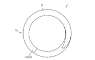
図1~図5に、それぞれ、本実施の形態に係るコイルばね1の自然長状態での正面図、上方斜視図、下方斜視図、平面図及び底面図を示す。
An embodiment of a coil spring according to the present invention will be described below with reference to the accompanying drawings.
1 to 5 show a front view, an upper perspective view, a lower perspective view, a plan view, and a bottom view, respectively, of the
図1~図5に示すように、本実施の形態に係るコイルばね1は、軸線方向一方側D1の第1端部101から軸線方向他方側D2の第2端部102へ向かってばね線材100が螺旋形状に成形されてなるものであり、内燃機関の弁ばねや高圧ポンプ用ばね等に好適に利用される。
なお、本実施の形態に係る前記コイルばね1においては、前記ばね線材100は断面円形とされているが、断面楕円形又は断面矩形等の種々の断面形状のばね線材を用いることができる。
As shown in FIGS. 1 to 5, the
In the
図1等に示すように、前記コイルばね1は、前記第1端部101を形成する外端部11から軸線方向他方側D2へ向かって周方向に沿って延びる第1座巻き部10と、前記第2端部102を形成する外端部21から軸線方向一方側D1へ向かって周方向に沿って延びる第2座巻き部20と、前記第1座巻き部10の軸線方向内端部12から軸線方向他方側D2へ向かって周方向に沿って螺旋状に延びて、前記第2座巻き部20の軸線方向内端部22に連結される中央巻き部30とを備えている。
As shown in FIG. 1 and the like, the
図6に、前記コイルばね1における巻き数と軸線方向変位量との関係を表すグラフを示す。
図6に示すように、本実施の形態に係るコイルばね1は、前記第1座巻き部10、前記中央巻き部30及び前記第2座巻き部20を含めて6巻きとされている。
FIG. 6 shows a graph representing the relationship between the number of turns of the
As shown in FIG. 6 , the
詳しくは、巻き数「0」の位置が前記第1端部101に対応し、巻き数「0」の位置から巻き数「1」の位置までの間が前記第1座巻き部10に相当する。
また、巻き数「6」の位置が前記第2端部102に対応し、巻き数「5」の位置から巻き数「6」の位置までの間が前記第2座巻き部20に相当しており、巻き数「1」の位置から巻き数「5」の位置までの間が前記中央巻き部30に相当している。
Specifically, the position of the number of turns "0" corresponds to the
Further, the position of the number of turns "6" corresponds to the
図1及び図6に示すように、前記第1座巻き部10は、軸線方向外端部11から内端部12までの間において軸線方向他方側D2へ前記ばね線材100の厚みaだけ変位されており、軸線方向外端部11及び前記中央巻き部30の軸線方向一方側D1の端部31の間の線間隙間がゼロとなっている。
As shown in FIGS. 1 and 6, the first
同様に、前記第2座巻き部20は、軸線方向外端部21から内端部22までの間において軸線方向一方側D1へ前記ばね線材の厚みaだけ変位されており、軸線方向外端部21及び前記中央巻き部30の軸線方向他方側D2の端部32の間の線間隙間がゼロとなっている。
Similarly, the second
前記第1及び第2座巻き部10、20には、それぞれ、軸線方向外方側の表面を研磨することによって前記コイルばね1の軸線方向に対して直交するように形成された、軸線方向外方を向く第1及び第2座面15、25が設けられている。
Each of the first and second
前記第1及び第2座面15、25は前記コイルばね1の設置面を形成するものである。 従って、前記コイルばね1の姿勢安定化を図って、前記コイルばね1の圧縮動作時に横力が発生することを有効に防止する為には、前記第1及び第2座面15、25を、前記コイルばね1の軸線方向に対して直交する状態で、前記コイルばね1の軸線回りに関し少なくとも半周に亘って設けることが好ましい。
The first and second seating surfaces 15 and 25 form mounting surfaces for the
しかしながら、前記コイルばね1の軸線方向に対して直交する状態の前記第1及び第2座面15、25を前記コイルばね1の軸線回りに関し拡げると、前記第1及び第2座巻き部10、20の軸線方向外端部11、21でのばね線材100の厚みが薄くなり、その結果、前記第1及び第2座巻き部10、20の剛性低下を招き、コイルばね1の圧縮動作時に横力の発生を招くことになる。
However, when the first and second seating surfaces 15 and 25 perpendicular to the axial direction of the
この点に関し、本実施の形態に係る前記コイルばね1は、下記構成を備えることにより、前記第1及び第2座面15、25を半周以上(詳しくは、図3及び図4に示すように、前記コイルばね1の軸線回りに約3/4周に亘って)設けつつ、前記第1座巻き部10(及び/又は前記第2座巻き部20)の剛性低下を有効に防止して横力の発生を有効に防止している。
Regarding this point, the
図7に、本実施の形態における巻き数及び軸線方向変位量の関係を示す。
図7には、本実施の形態の変形例及び従来例における巻き数及び軸線方向変位量の関係も併せて示している。
FIG. 7 shows the relationship between the number of turns and the amount of displacement in the axial direction in this embodiment.
FIG. 7 also shows the relationship between the number of turns and the amount of displacement in the axial direction in the modified example of the present embodiment and the conventional example.
図7に示すように、従来のコイルばねにおいては、巻き数「0」(第1座巻き部10の外端部11に相当する位置)及び巻き数「1」(第1座巻き部10の内端部に相当する位置)の間の軸線方向変位量は、ばね線材の厚みをaとした場合に、傾きaの一定割合で変化するように構成されている。
As shown in FIG. 7, in the conventional coil spring, the number of turns is "0" (the position corresponding to the
即ち、従来のコイルばねにおいては、巻き数「1/4」の位置においては、軸線方向変位量はa/4となり、巻き数「1/2」の位置(第1座巻き部10の外端部11に相当する位置から内端部12に相当する位置へ向かって半周だけ進んだ位置)においては、軸線方向変位量はa/2となる。
That is, in the conventional coil spring, the amount of displacement in the axial direction is a/4 at the position of the number of turns "1/4", and the position of the number of turns "1/2" (outer end of the first end turn portion 10) At the position corresponding to the
これに対し、本実施の形態に係るコイルばね1においては、前記第1座巻き部10の軸線方向外端部11と当該外端部11から内端部12へ向けて周方向に半周だけ進んだ地点との間の軸線方向変位量は前記ばね線材100の厚みaの半分よりも小さくなるように構成されている。
On the other hand, in the
斯かる構成を備えたコイルばね1によれば、前記第1座面15を軸線回りに半周に亘って設けたとしても、前記第1座巻き部10の外端部11での厚みをばね線材100の厚みの1/2以上確保することができ、これにより、前記第1座巻き部10の剛性を有効に確保することができる。
According to the
図1及び図7に示すように、前記コイルばね1においては、前記第1座巻き部10の外端部11から半周を越えた第1変曲点C1(本実施の形態においては巻き数「3/4」の地点)までの間は軸線方向変位量が実質的にゼロとされ、第1変曲点C1から前記第1座巻き部10の内端部12(巻き数「1」の地点)までの間にばね線材100の厚みaに相当する量だけ軸線方向に変位するように構成されている。
As shown in FIGS. 1 and 7, in the
斯かる構成によれば、前記第1座面15を3/4周に亘って設けても、前記第1座巻き部10の外端部11での厚みをa/2以上、確保することができる。
According to such a configuration, even if the
図8に、図6におけるVIII部の拡大図を示す。
図8には、本実施の形態の変形例及び従来例における巻き数及び軸線方向変位量の関係も併せて示している。
FIG. 8 shows an enlarged view of the VIII section in FIG.
FIG. 8 also shows the relationship between the number of turns and the amount of displacement in the axial direction in the modified example of the present embodiment and the conventional example.
図8に示すように、前記第2座巻き部20についても同様に、前記第2座巻き部20の外端部21から内端部22へ向けて半周を越えた第2変曲点C2(本実施の形態においては前記第2座巻き部20の外端部21から軸線方向一方側へ3/4周の地点)までの間は軸線方向変位量が実質的にゼロとされ、第2変曲点C2から前記第2座巻き部20の内端部22までの間にばね線材100の厚みaに相当する量だけ軸線方向に変位するように構成されている。
As shown in FIG. 8, for the second
斯かる構成によれば、前記第2座面25を3/4周に亘って設けても、前記第2座巻き部20の外端部21での厚みをa/2以上、確保することができる。
According to such a configuration, even if the
これに代えて、図7に併せて示す変形例のように、巻き数「0」(前記第1座巻き部10の外端部11に相当する位置)と巻き数「1/2」(外端部11から内端部12へ向けて周方向に半周だけ進んだ位置)との間の軸線方向変位量がばね線材100の厚みaの半分より小さくなるように、前記第1座巻き部10の外端部11から内端部12へ向けて周方向に沿って進む周方向移動量と軸線方向他方側への軸線方向変位量とが上方に開く曲線状の関係となるように、前記第1座巻き部10を形成することも可能である。
Instead of this, as in a modification shown in FIG. the first
図8に併せて示す変形例のように、前記第2座巻き部20は、内端部22と前記内端部22から外端部21へ向けて周方向に半周だけ進んだ位置との間の軸線方向他方側への変位量がばね線材の厚みaの半分より大きくなるように、前記内端部22から前記外端部21へ向けて周方向に沿って進む周方向移動量と軸線方向他方側変位量とが下方に開く曲線状となるように構成されている(即ち、前記第2座巻き部20の外端部21を基準点として表現すると、前記第2座巻き部20の外端部21と前記外端部21から内端部22へ向けて周方向に半周だけ進んだ位置との間の軸線方向一方側変位量がばね線材100の厚みaの半分より小さくなるように、前記第2座巻き部20の外端部21から内端部22へ向けて周方向に沿って進む周方向移動量と軸線方向一方側への軸線方向変位量とが下方に開く曲線状の関係となるように、前記第2座巻き部20が構成されている。)
斯かる変形例によっても、本実施の形態におけると同様の効果を得ることができる。
8, the second
Such a modified example can also provide the same effects as in the present embodiment.
また、本実施の形態に係るコイルばね1においては、前記第1座巻き部10の外端部11及び前記第2座巻き部20の外端部21の周方向位置を一致させており、これによっても、圧縮動作の横力発生を有効に防止している。
In the
さらに、本実施の形態に係るコイルばね1は、軸線方向に隣接するばね線材100間の線間隙間によって画される線間巻きに関し、下記構成を備えている。
図9に、前記コイルばね1における線間巻き数と線間隙間との関係を表すグラフを示す。
なお、図9に示す線間巻き数「0」~「5」は、図6に示す巻きの「1」~「6」に相当する。
Further, the
FIG. 9 shows a graph representing the relationship between the number of windings between wires and the gap between wires in the
Note that the number of windings between lines "0" to "5" shown in FIG. 9 corresponds to windings "1" to "6" shown in FIG.
詳しくは、図1~図3、図5及び図9に示すように、前記コイルばね1は、前記線間巻きが、前記中央巻き部30の軸線方向一方側の端部31及び前記第1座巻き部10の外端部11の間において線間隙間がゼロとされた第1線間隙間ゼロ点60aから軸線方向他方側D2へ周方向に沿って進むに従って線間隙間が大きくなる第1変化領域61と、前記第1変化領域61よりも軸線方向他方側D2に位置し、線間隙間が基準値Lのままで軸線方向他方側D2へ周方向に沿って延びる基準領域65と、前記基準領域65よりも軸線方向他方側D2に位置し、軸線方向他方側D2へ周方向に沿って進むに従って線間隙間が小さくなって線間隙間がゼロとされた第2線間隙間ゼロ点60bで終焉する第2変化領域69とを有するように、構成されている。
Specifically, as shown in FIGS. 1 to 3, 5, and 9, the
図9に示すように、本実施の形態に係るコイルばね1は、前記第1変化領域61が軸線方向外端の前記第1線間隙間ゼロ点60aから軸線方向他方側D2へ周方向に1巻き未満の位置で終焉し且つ軸線方向内端の終端での線間隙間が基準値Lよりも大とされ、前記第2変化領域69が軸線方向外端の前記第2線間隙間ゼロ点60bから軸線方向一方側D1へ周方向に1巻き未満の位置で終焉し且つ軸線方向内端の終端での線間隙間が基準値Lよりも大とされており、さらに、前記線間巻きが、前記第1変化領域61及び前記基準領域65の間に位置し、前記第1変化領域61の終端から前記基準領域65の軸線方向一方側D1の端部へ向かって周方向に進むに従って線間距離が小さくなって基準値Lとなる第1移行領域63と、前記第2変化領域69及び前記基準領域65の間に位置し、前記第2変化領域69の終端から前記基準領域65の軸線方向他方側D2の端部へ向かって周方向に進むに従って線間距離が小さくなって基準値Lとなる第2移行領域67とを有するように、構成されている。
As shown in FIG. 9, in the
かかる構成を備えることにより、前記コイルばね1が自然長状態から圧縮される際に、前記第1及び第2変化領域61、69中に線間隙間ゼロが生じることを有効に防止でき、圧縮動作時の横力の発生を有効に抑えることができる。
With such a configuration, when the
即ち、前記コイルばね1においては、軸線方向両端部側に位置する前記第1及び第2変化領域61、69の終端(軸線方向内端)での線間距離が基準値Lよりも大とされている。
従って、前記コイルばね1の圧縮動作に、軸線方向一方側D1及び他方側D2において、隣接するばね線材100が意に反して接触して有効巻き数に変化を生じさせることを有効に防止でき、これにより、圧縮動作時の横力発生を有効に抑えることができる。
That is, in the
Therefore, it is possible to effectively prevent the adjacent
前記コイルばね1は、例えば、図10に示す製造装置200によって製造される。
図10に示すように、前記製造装置200は、ばね線材100を供給する供給ローラ210と、前記供給ローラ210によって搬送されるばね線材100をガイドするガイド部材215と、前記ガイド部材215によってガイドされた状態で前記供給ローラ210によって搬送されるばね線材100の搬送方向下流側に設けられ、直線状のばね線材100を螺旋状のコイルばね1に成形する第1及び第2コイリングツール220(1)、220(2)と、前記第1及び第2コイリングツール220(1)、220(2)によって螺旋状に成形されたコイルばね1をガイドする芯金部材225と、前記コイルばね1のピッチを調整するピッチツール230と、前記芯金225と共働してばね線材100を切断する切断ツール235とを有している。
The
As shown in FIG. 10, the
前記第1及び第2コイリングツール220(1)、220(2)は、成形されるコイルばね1の中心を基準とした径方向に関し位置調整可能とされており、径方向位置の変更に応じてコイルばね1のコイル径を変更する。
The first and second coiling tools 220(1) and 220(2) are adjustable in position in the radial direction with the center of the
前記ピッチツール230は、コイルばね1の中心を基準とした径方向に関し位置調整可能とされており、径方向位置の変更に応じてコイルばね1のピッチを変更する。
The
前記切断ツール235は、コイルばね1の中心を基準とした径方向に関し往復動可能とされており、前記芯金225の係合面226と共働して前記ばね線材100を切断する切断位置と前記芯金225から離間された退避位置との間で移動可能とされている。
The
1 コイルばね
10 第1座巻き部
11 第1座巻き部の外端部
12 第1座巻き部の内端部
20 第2座巻き部
21 第2座巻き部の外端部
22 第2座巻き部の内端部
30 中央巻き部
31 中央巻き部の軸線方向一方側の端部
32 中央巻き部の軸線方向他方側の端部
60a 第1線間隙間ゼロ点
60b 第2線間隙間ゼロ点
61 第1変化領域
63 第1移行領域
65 基準領域
67 第2移行領域
69 第2変化領域
100 ばね線材
101 第1端部
102 第2端部
C1 第1変曲点
C2 第2変曲点
D1 軸線方向一方側
D2 軸線方向他方側
1
Claims (6)
軸線方向一方側を向く第1座面を有し、前記第1端部を形成する外端部から軸線方向他方側の内端部へ向かって周方向に沿って延びる第1座巻き部と、軸線方向他方側を向く第2座面を有し、前記第2端部を形成する外端部から軸線方向一方側の内端部へ向かって周方向に沿って延びる第2座巻き部と、前記第1座巻き部の内端部から軸線方向他方側へ向かって周方向に沿って螺旋状に延びて、前記第2座巻き部の内端部に連結される中央巻き部とを備え、
前記中央巻き部の軸線方向一方側の端部及び前記第1座巻き部の外端部の間の線間隙間がゼロとなるように前記第1座巻き部の外端部から内端部までの間の軸線方向他方側への前記ばね線材の中心位置の変位量が前記ばね線材の厚みとされた上で、前記第1座巻き部の外端部から内端部へ向けて進むに従って前記ばね線材の中心位置が徐々に軸線方向他方側に位置されつつ、前記第1座巻き部の外端部と当該外端部から前記第1座巻き部の内端部へ向けて半周だけ進んだ地点との間の軸線方向他方側への前記ばね線材の中心位置の変位量は前記ばね線材の厚みの1/4よりも小とされ、且つ、前記第1座巻き部の外端部から内端部へ向けて周方向に沿って進む前記ばね線材の周方向移動量と前記第1座巻き部の外端部からの軸線方向他方側への前記ばね線材の中心位置の軸線方向変位量との関係が、前記座巻き部の外端部から内端部までの全域に亘って上方に開く曲線とされており、
前記曲線は、当該曲線に対する接線の傾きが前記座巻き部の外端部から内端部へ進むに従って大きくなる形状とされていることを特徴とするコイルばね。 A coil spring formed by forming a spring wire into a helical shape from a first end on one side in the axial direction toward a second end on the other side in the axial direction,
a first end turn portion having a first bearing surface facing one side in the axial direction and extending along the circumferential direction from an outer end portion forming the first end portion toward an inner end portion on the other side in the axial direction; a second end turn portion having a second bearing surface facing the other side in the axial direction and extending along the circumferential direction from an outer end portion forming the second end portion toward an inner end portion on the one side in the axial direction; a center winding portion spirally extending along the circumferential direction from the inner end portion of the first end turn portion toward the other side in the axial direction and connected to the inner end portion of the second end turn portion;
from the outer end to the inner end of the first end turn so that the line gap between the end of the center turn on one side in the axial direction and the outer end of the first end turn is zero. The amount of displacement of the center position of the spring wire to the other side in the axial direction between the While the center position of the spring wire is gradually positioned on the other side in the axial direction, the outer end portion of the first end turn portion advances from the outer end portion toward the inner end portion of the first end turn portion by half a turn. The amount of displacement of the center position of the spring wire to the other side in the axial direction between the points is smaller than 1/4 of the thickness of the spring wire, and the displacement from the outer end of the first end turn portion to the inside A circumferential movement amount of the spring wire advancing along the circumferential direction toward the end portion and an axial displacement amount of the center position of the spring wire toward the other side in the axial direction from the outer end portion of the first end turn portion is a curve that opens upward over the entire area from the outer end to the inner end of the end turn portion,
The coil spring, wherein the curve has a shape in which a slope of a tangent line to the curve increases as it progresses from the outer end portion to the inner end portion of the end turn portion.
軸線方向一方側を向く第1座面を有し、前記第1端部を形成する外端部から軸線方向他方側の内端部へ向かって周方向に沿って延びる第1座巻き部と、軸線方向他方側を向く第2座面を有し、前記第2端部を形成する外端部から軸線方向一方側の内端部へ向かって周方向に沿って延びる第2座巻き部と、前記第1座巻き部の内端部から軸線方向他方側へ向かって周方向に沿って螺旋状に延びて、前記第2座巻き部の内端部に連結される中央巻き部とを備え、
前記中央巻き部の軸線方向一方側の端部及び前記第1座巻き部の外端部の間の線間隙間がゼロとなるように前記第1座巻き部の外端部から内端部までの間の軸線方向他方側への前記ばね線材の中心位置の変位量が前記ばね線材の厚みとされた上で、前記第1座巻き部の外端部から内端部へ向けて進むに従って前記ばね線材の中心位置が徐々に軸線方向他方側に位置されつつ、前記第1座巻き部の外端部と当該外端部から前記第1座巻き部の内端部へ向けて半周だけ進んだ地点との間の軸線方向他方側への前記ばね線材の中心位置の変位量は前記ばね線材の厚みの1/4よりも小とされ、且つ、前記第1座巻き部の外端部から内端部へ向けて周方向に沿って進む前記ばね線材の周方向移動量と前記第1座巻き部の外端部からの軸線方向他方側への前記ばね線材の中心位置の軸線方向変位量との関係が上方に開く曲線状とされていることを特徴とするコイルばね。 A coil spring formed by forming a spring wire into a helical shape from a first end on one side in the axial direction toward a second end on the other side in the axial direction,
a first end turn portion having a first bearing surface facing one side in the axial direction and extending along the circumferential direction from an outer end portion forming the first end portion toward an inner end portion on the other side in the axial direction; a second end turn portion having a second bearing surface facing the other side in the axial direction and extending along the circumferential direction from an outer end portion forming the second end portion toward an inner end portion on the one side in the axial direction; a center winding portion spirally extending along the circumferential direction from the inner end portion of the first end turn portion toward the other side in the axial direction and connected to the inner end portion of the second end turn portion;
from the outer end to the inner end of the first end turn so that the line gap between the end of the center turn on one side in the axial direction and the outer end of the first end turn is zero. The amount of displacement of the center position of the spring wire to the other side in the axial direction between the While the center position of the spring wire is gradually positioned on the other side in the axial direction, the outer end portion of the first end turn portion advances from the outer end portion toward the inner end portion of the first end turn portion by half a turn. The amount of displacement of the center position of the spring wire to the other side in the axial direction between the points is smaller than 1/4 of the thickness of the spring wire, and the displacement from the outer end of the first end turn portion to the inside A circumferential movement amount of the spring wire advancing along the circumferential direction toward the end portion and an axial displacement amount of the center position of the spring wire toward the other side in the axial direction from the outer end portion of the first end turn portion A coil spring characterized in that the relationship between is a curved shape that opens upward.
前記第1変化領域は、軸線方向外端の前記第1線間隙間ゼロ点から軸線方向他方側へ向かって周方向に1巻き未満の位置で終焉し且つ軸線方向内端の終端での線間隙間が基準値よりも大きくなるように構成されており、
前記第1変化領域及び前記基準領域の間には、前記第1変化領域の終端から前記基準領域の軸線方向一方側の端部へ向かって周方向に進むに従って線間距離が小さくなって基準値となる第1移行領域が設けられていることを特徴とする請求項1又は2に記載のコイルばね。 A line-to-line winding defined by a line-to-line gap between axially adjacent spring wires has a line-to-line gap between the axially one-side end of the central winding portion and the outer end portion of the first end turn portion. a first change region in which the line gap increases as it progresses along the circumferential direction from the first line gap zero point where the is zero to the other side in the axial direction; and a reference region extending along the circumferential direction to the other side in the axial direction with the line gap remaining at the reference value,
The first change region ends at a position less than one turn in the circumferential direction from the zero point of the first inter-wire gap at the axial outer end toward the other axial direction side, and the inter-wire gap at the terminal end of the axial inner end. The gap is configured to be larger than the standard value,
Between the first change region and the reference region, the line-to-line distance becomes smaller as it progresses in the circumferential direction from the terminal end of the first change region toward the end of the reference region on one side in the axial direction. 3. A coil spring according to claim 1 or 2, characterized in that there is provided a first transition region where
軸線方向一方側を向く第1座面を有し、前記第1端部を形成する外端部から軸線方向他方側の内端部へ向かって周方向に沿って延びる第1座巻き部と、軸線方向他方側を向く第2座面を有し、前記第2端部を形成する外端部から軸線方向一方側の内端部へ向かって周方向に沿って延びる第2座巻き部と、前記第1座巻き部の内端部から軸線方向他方側へ向かって周方向に沿って螺旋状に延びて、前記第2座巻き部の内端部に連結される中央巻き部とを備え、
前記中央巻き部の軸線方向一方側の端部及び前記第1座巻き部の外端部の間の線間隙間がゼロとなるように前記第1座巻き部の外端部から内端部までの間の軸線方向他方側への前記ばね線材の中心位置の変位量が前記ばね線材の厚みとされた上で、前記第1座巻き部の外端部から内端部へ向けて進むに従って前記ばね線材の中心位置が徐々に軸線方向他方側に位置されつつ、前記第1座巻き部の外端部と当該外端部から前記第1座巻き部の内端部へ向けて半周だけ進んだ地点との間の軸線方向他方側への前記ばね線材の中心位置の変位量は前記ばね線材の厚みの1/4よりも小とされ、且つ、前記第1座巻き部の外端部から内端部へ向けて周方向に沿って進む前記ばね線材の周方向移動量と前記第1座巻き部の外端部からの軸線方向他方側への前記ばね線材の中心位置の軸線方向変位量との関係が上方に開く曲線状とされ、
前記中央巻き部の軸線方向他方側の端部及び前記第2座巻き部の外端部の間の線間隙間がゼロとなるように前記第2座巻き部の外端部から内端部までの間の軸線方向一方側への前記ばね線材の中心位置の変位量が前記ばね線材の厚みとされた上で、前記第2座巻き部の外端部から内端部へ向けて進むに従って前記ばね線材の中心位置が徐々に軸線方向一方側に位置されつつ、前記第2座巻き部の外端部と当該外端部から前記第2座巻き部の内端部へ向けて半周だけ進んだ地点との間の軸線方向一方側への前記ばね線材の中心位置の変位量は前記ばね線材の厚みの1/4よりも小とされ、且つ、前記第2座巻き部の外端部から内端部へ向けて周方向に沿って進む前記ばね線材の周方向移動量と前記第2座巻き部の外端部からの軸線方向一方側への前記ばね線材の中心位置の軸線方向変位量との関係が、前記第2座巻き部の外端部から内端部までの全域に亘って下方に開く曲線とされており、
前記曲線は、当該曲線に対する接線の傾きが前記第2座巻き部の外端部から内端部へ進むに従って大きくなる形状とされていることを特徴とするコイルばね。 A coil spring formed by forming a spring wire into a helical shape from a first end on one side in the axial direction toward a second end on the other side in the axial direction,
a first end turn portion having a first bearing surface facing one side in the axial direction and extending along the circumferential direction from an outer end portion forming the first end portion toward an inner end portion on the other side in the axial direction; a second end turn portion having a second bearing surface facing the other side in the axial direction and extending along the circumferential direction from an outer end portion forming the second end portion toward an inner end portion on the one side in the axial direction; a center winding portion spirally extending along the circumferential direction from the inner end portion of the first end turn portion toward the other side in the axial direction and connected to the inner end portion of the second end turn portion;
from the outer end to the inner end of the first end turn so that the line gap between the end of the center turn on one side in the axial direction and the outer end of the first end turn is zero. The amount of displacement of the center position of the spring wire to the other side in the axial direction between the While the center position of the spring wire is gradually positioned on the other side in the axial direction, the outer end portion of the first end turn portion advances from the outer end portion toward the inner end portion of the first end turn portion by half a turn. The amount of displacement of the center position of the spring wire to the other side in the axial direction between the points is smaller than 1/4 of the thickness of the spring wire, and the displacement from the outer end of the first end turn portion to the inside A circumferential movement amount of the spring wire advancing along the circumferential direction toward the end portion and an axial displacement amount of the center position of the spring wire toward the other side in the axial direction from the outer end portion of the first end turn portion is a curved line that opens upward,
from the outer end to the inner end of the second end turn so that the line gap between the end of the center turn on the other side in the axial direction and the outer end of the second end turn is zero. The amount of displacement of the center position of the spring wire to one side in the axial direction between the While the center position of the spring wire is gradually positioned on one side in the axial direction, the outer end portion of the second end turn portion advances from the outer end portion toward the inner end portion of the second end turn portion by half a turn. The amount of displacement of the center position of the spring wire to one side in the axial direction between the points is smaller than 1/4 of the thickness of the spring wire, and the displacement from the outer end of the second end turn portion to the inside A circumferential movement amount of the spring wire advancing along the circumferential direction toward the end portion and an axial displacement amount of the center position of the spring wire toward one axial direction side from the outer end portion of the second end turn portion is a curve that opens downward over the entire area from the outer end to the inner end of the second end turn portion,
The coil spring, wherein the curve has a shape in which a slope of a tangent line to the curve increases from the outer end portion to the inner end portion of the second end turn portion.
軸線方向一方側を向く第1座面を有し、前記第1端部を形成する外端部から軸線方向他方側の内端部へ向かって周方向に沿って延びる第1座巻き部と、軸線方向他方側を向く第2座面を有し、前記第2端部を形成する外端部から軸線方向一方側の内端部へ向かって周方向に沿って延びる第2座巻き部と、前記第1座巻き部の内端部から軸線方向他方側へ向かって周方向に沿って螺旋状に延びて、前記第2座巻き部の内端部に連結される中央巻き部とを備え、
前記中央巻き部の軸線方向一方側の端部及び前記第1座巻き部の外端部の間の線間隙間がゼロとなるように前記第1座巻き部の外端部から内端部までの間の軸線方向他方側への前記ばね線材の中心位置の変位量が前記ばね線材の厚みとされた上で、前記第1座巻き部の外端部から内端部へ向けて進むに従って前記ばね線材の中心位置が徐々に軸線方向他方側に位置されつつ、前記第1座巻き部の外端部と当該外端部から前記第1座巻き部の内端部へ向けて半周だけ進んだ地点との間の軸線方向他方側への前記ばね線材の中心位置の変位量は前記ばね線材の厚みの1/4よりも小とされ、且つ、前記第1座巻き部の外端部から内端部へ向けて周方向に沿って進む前記ばね線材の周方向移動量と前記第1座巻き部の外端部からの軸線方向他方側への前記ばね線材の中心位置の軸線方向変位量との関係が上方に開く曲線状とされ、
前記中央巻き部の軸線方向他方側の端部及び前記第2座巻き部の外端部の間の線間隙間がゼロとなるように前記第2座巻き部の外端部から内端部までの間の軸線方向一方側への前記ばね線材の中心位置の変位量が前記ばね線材の厚みとされた上で、前記第2座巻き部の外端部から内端部へ向けて進むに従って前記ばね線材の中心位置が徐々に軸線方向一方側に位置されつつ、前記第2座巻き部の外端部と当該外端部から前記第2座巻き部の内端部へ向けて半周だけ進んだ地点との間の軸線方向一方側への前記ばね線材の中心位置の変位量は前記ばね線材の厚みの1/4よりも小とされ、且つ、前記第2座巻き部の外端部から内端部へ向けて周方向に沿って進む前記ばね線材の周方向移動量と前記第2座巻き部の外端部からの軸線方向一方側への前記ばね線材の中心位置の軸線方向変位量との関係が下方に開く曲線状とされていることを特徴とするコイルばね。 A coil spring formed by forming a spring wire into a helical shape from a first end on one side in the axial direction toward a second end on the other side in the axial direction,
a first end turn portion having a first bearing surface facing one side in the axial direction and extending along the circumferential direction from an outer end portion forming the first end portion toward an inner end portion on the other side in the axial direction; a second end turn portion having a second bearing surface facing the other side in the axial direction and extending along the circumferential direction from an outer end portion forming the second end portion toward an inner end portion on the one side in the axial direction; a center winding portion spirally extending along the circumferential direction from the inner end portion of the first end turn portion toward the other side in the axial direction and connected to the inner end portion of the second end turn portion;
from the outer end to the inner end of the first end turn so that the line gap between the end of the center turn on one side in the axial direction and the outer end of the first end turn is zero. The amount of displacement of the center position of the spring wire to the other side in the axial direction between the While the center position of the spring wire is gradually positioned on the other side in the axial direction, the outer end portion of the first end turn portion advances from the outer end portion toward the inner end portion of the first end turn portion by half a turn. The amount of displacement of the center position of the spring wire to the other side in the axial direction between the points is smaller than 1/4 of the thickness of the spring wire, and the displacement from the outer end of the first end turn portion to the inside A circumferential movement amount of the spring wire advancing along the circumferential direction toward the end portion and an axial displacement amount of the center position of the spring wire toward the other side in the axial direction from the outer end portion of the first end turn portion is a curved line that opens upward,
from the outer end to the inner end of the second end turn so that the line gap between the end of the center turn on the other side in the axial direction and the outer end of the second end turn is zero. The amount of displacement of the center position of the spring wire to one side in the axial direction between the While the center position of the spring wire is gradually positioned on one side in the axial direction, the outer end portion of the second end turn portion advances from the outer end portion toward the inner end portion of the second end turn portion by half a turn. The amount of displacement of the center position of the spring wire to one side in the axial direction between the points is smaller than 1/4 of the thickness of the spring wire, and the displacement from the outer end of the second end turn portion to the inside A circumferential movement amount of the spring wire advancing along the circumferential direction toward the end portion and an axial displacement amount of the center position of the spring wire toward one axial direction side from the outer end portion of the second end turn portion A coil spring characterized in that the relationship between is a curved shape that opens downward.
前記第1変化領域は、軸線方向外端の前記第1線間隙間ゼロ点から軸線方向他方側へ周方向に1巻き未満の位置で終焉し且つ軸線方向内端の終端での線間隙間が基準値よりも大きくなるように構成され、前記第2変化領域は、軸線方向外端の前記第2線間隙間ゼロ点から軸線方向一方側へ周方向に1巻き未満の位置で終焉し且つ軸線方向内端の終端での線間隙間が基準値よりも大きくなるように構成され、
前記第1変化領域及び前記基準領域の間には、前記第1変化領域の終端から前記基準領域の軸線方向一方側の端部へ向かって周方向に進むに従って線間距離が小さくなって基準値となる第1移行領域が設けられ、前記第2変化領域及び前記基準領域の間には、前記第2変化領域の終端から前記基準領域の軸線方向他方側の端部へ向かって周方向に進むに従って線間距離が小さくなって基準値となる第2移行領域が設けられていることを特徴とする請求項4又は5に記載のコイルばね。 A line-to-line winding defined by a line-to-line gap between axially adjacent spring wires has a line-to-line gap between the axially one-side end of the central winding portion and the outer end portion of the first end turn portion. a first change region in which the line gap increases as it progresses along the circumferential direction from the first line gap zero point where the is zero to the other side in the axial direction; A reference area extending along the other side in the axial direction with the line gap remaining at the reference value, and a reference area located on the other side in the axial direction of the reference area and extending along the other side in the axial direction along the circumferential direction. a second change region ending at the second zero point of the line gap where the line gap becomes zero and the line gap becomes zero according to
The first change region ends at a position of less than one turn in the circumferential direction from the zero point of the first gap between lines at the outer end in the axial direction to the other side in the axial direction, and the gap at the end of the inner end in the axial direction is The second change region ends at a position less than one turn in the circumferential direction from the zero point of the second gap between the wires at the axial outer end to one side in the axial direction, and extends along the axial direction. The line gap at the end of the direction inner end is configured to be larger than the reference value,
Between the first change region and the reference region, the line-to-line distance becomes smaller as it progresses in the circumferential direction from the terminal end of the first change region toward the end of the reference region on one side in the axial direction. Between the second change region and the reference region, progresses in the circumferential direction from the end of the second change region toward the other end in the axial direction of the reference region 6. The coil spring according to claim 4 or 5, wherein a second transition region is provided in which the line-to-line distance becomes smaller according to the distance and becomes the reference value.
Priority Applications (5)
| Application Number | Priority Date | Filing Date | Title |
|---|---|---|---|
| JP2018094718A JP7182377B2 (en) | 2018-05-16 | 2018-05-16 | coil spring |
| CN201980031984.0A CN112135986B (en) | 2018-05-16 | 2019-04-24 | Spiral spring |
| EP19803031.4A EP3786475A4 (en) | 2018-05-16 | 2019-04-24 | Coil spring |
| PCT/JP2019/017355 WO2019220892A1 (en) | 2018-05-16 | 2019-04-24 | Coil spring |
| US17/055,417 US11499600B2 (en) | 2018-05-16 | 2019-04-24 | Coil spring |
Applications Claiming Priority (1)
| Application Number | Priority Date | Filing Date | Title |
|---|---|---|---|
| JP2018094718A JP7182377B2 (en) | 2018-05-16 | 2018-05-16 | coil spring |
Publications (2)
| Publication Number | Publication Date |
|---|---|
| JP2019199916A JP2019199916A (en) | 2019-11-21 |
| JP7182377B2 true JP7182377B2 (en) | 2022-12-02 |
Family
ID=68539816
Family Applications (1)
| Application Number | Title | Priority Date | Filing Date |
|---|---|---|---|
| JP2018094718A Active JP7182377B2 (en) | 2018-05-16 | 2018-05-16 | coil spring |
Country Status (5)
| Country | Link |
|---|---|
| US (1) | US11499600B2 (en) |
| EP (1) | EP3786475A4 (en) |
| JP (1) | JP7182377B2 (en) |
| CN (1) | CN112135986B (en) |
| WO (1) | WO2019220892A1 (en) |
Families Citing this family (2)
| Publication number | Priority date | Publication date | Assignee | Title |
|---|---|---|---|---|
| JP6367256B2 (en) * | 2016-04-13 | 2018-08-01 | サンコール株式会社 | Coil spring |
| CN113669396B (en) * | 2021-08-20 | 2022-12-02 | 安庆谢德尔汽车零部件有限公司 | Compression spring with prepressing end and winding and detecting method thereof |
Citations (2)
| Publication number | Priority date | Publication date | Assignee | Title |
|---|---|---|---|---|
| JP2006077904A (en) | 2004-09-10 | 2006-03-23 | Bosch Corp | Coil spring and fluid pressure booster using the same |
| JP2017190823A (en) | 2016-04-13 | 2017-10-19 | サンコール株式会社 | Coil spring |
Family Cites Families (19)
| Publication number | Priority date | Publication date | Assignee | Title |
|---|---|---|---|---|
| US2260606A (en) | 1938-08-19 | 1941-10-28 | Eaton Mfg Co | Coiled spring |
| JPS6323257Y2 (en) | 1979-10-01 | 1988-06-24 | ||
| FR2550295B1 (en) | 1983-08-03 | 1989-01-27 | Latty Cyril | CYLINDRICAL HELICAL SPRING, PARTICULARLY FOR MECHANICAL SEALING |
| JPH01128034U (en) * | 1988-02-25 | 1989-08-31 | ||
| DE29612307U1 (en) * | 1996-07-16 | 1996-09-12 | Heinz Hofmann Gmbh | Spring |
| JP3936427B2 (en) | 1997-04-08 | 2007-06-27 | Nskワーナー株式会社 | Compression coil spring |
| JP3960710B2 (en) | 1998-07-31 | 2007-08-15 | 中央発條株式会社 | Suspension coil spring for automobile |
| JP2000205320A (en) | 1999-01-12 | 2000-07-25 | Suncall Corp | Valve spring of internal combustion engine |
| KR20040080470A (en) * | 2003-03-11 | 2004-09-20 | 엘지전자 주식회사 | Mounting structure for control box of Airconditioner |
| JP4146298B2 (en) | 2003-06-26 | 2008-09-10 | トヨタ自動車株式会社 | Coil spring |
| US7766312B2 (en) * | 2005-05-31 | 2010-08-03 | Nhk Spring Co., Ltd. | Coil spring |
| US7857294B2 (en) * | 2008-03-28 | 2010-12-28 | Spencer Composites Corporation | Composite springs and methods of manufacture |
| JP5313210B2 (en) | 2010-06-30 | 2013-10-09 | 三菱製鋼株式会社 | Coil spring |
| US20140262498A1 (en) * | 2013-03-13 | 2014-09-18 | U.S.A. As Represented By The Administrator Of The National Aeronautics And Space Administration | Interconnect Device and Assemblies Made Therewith |
| MX2016016937A (en) * | 2014-06-19 | 2017-04-27 | Nhk Spring Co Ltd | Coiled spring assembly. |
| JP6350416B2 (en) * | 2015-06-30 | 2018-07-04 | 株式会社デンソー | High pressure pump |
| CN109073020A (en) * | 2016-03-23 | 2018-12-21 | 日本发条株式会社 | Helical spring |
| US10995811B2 (en) * | 2016-03-31 | 2021-05-04 | Nhk Spring Co., Ltd. | Coil spring |
| JP6367257B2 (en) | 2016-04-13 | 2018-08-01 | サンコール株式会社 | Coil spring |
-
2018
- 2018-05-16 JP JP2018094718A patent/JP7182377B2/en active Active
-
2019
- 2019-04-24 WO PCT/JP2019/017355 patent/WO2019220892A1/en unknown
- 2019-04-24 US US17/055,417 patent/US11499600B2/en active Active
- 2019-04-24 CN CN201980031984.0A patent/CN112135986B/en active Active
- 2019-04-24 EP EP19803031.4A patent/EP3786475A4/en active Pending
Patent Citations (2)
| Publication number | Priority date | Publication date | Assignee | Title |
|---|---|---|---|---|
| JP2006077904A (en) | 2004-09-10 | 2006-03-23 | Bosch Corp | Coil spring and fluid pressure booster using the same |
| JP2017190823A (en) | 2016-04-13 | 2017-10-19 | サンコール株式会社 | Coil spring |
Also Published As
| Publication number | Publication date |
|---|---|
| CN112135986B (en) | 2023-10-20 |
| WO2019220892A1 (en) | 2019-11-21 |
| EP3786475A4 (en) | 2022-02-23 |
| US20210190163A1 (en) | 2021-06-24 |
| CN112135986A (en) | 2020-12-25 |
| US11499600B2 (en) | 2022-11-15 |
| JP2019199916A (en) | 2019-11-21 |
| EP3786475A1 (en) | 2021-03-03 |
Similar Documents
| Publication | Publication Date | Title |
|---|---|---|
| WO2017179274A1 (en) | Coil spring | |
| JP7182377B2 (en) | coil spring | |
| US20180209504A1 (en) | Spring structure having multiple coil-shaped unit springs and method for manufacturing same | |
| JP5954243B2 (en) | Method for manufacturing aggregate conductor | |
| CN102959270A (en) | Coil spring | |
| JP2024010095A (en) | coil spring | |
| CN108779823B (en) | Spiral spring | |
| JP6367256B2 (en) | Coil spring | |
| JP4358828B2 (en) | Coil expander wire and coil expander | |
| JP6637093B2 (en) | Coil spring | |
| WO2015047395A1 (en) | Milanese mesh rolling | |
| JP4834057B2 (en) | Coil manufacturing method | |
| KR101468303B1 (en) | Spring of oil pump for vehicle | |
| JP6153750B2 (en) | Spiral spring and manufacturing method thereof | |
| JPH0534824Y2 (en) | ||
| JP2017119301A (en) | Spiral processing device for a wire, and spiral processing method for a wire | |
| JP2007010096A (en) | Combined ring and its spacer expander, and its manufacturing method |
Legal Events
| Date | Code | Title | Description |
|---|---|---|---|
| A621 | Written request for application examination |
Free format text: JAPANESE INTERMEDIATE CODE: A621 Effective date: 20200615 |
|
| A131 | Notification of reasons for refusal |
Free format text: JAPANESE INTERMEDIATE CODE: A131 Effective date: 20210702 |
|
| A601 | Written request for extension of time |
Free format text: JAPANESE INTERMEDIATE CODE: A601 Effective date: 20210819 |
|
| A521 | Request for written amendment filed |
Free format text: JAPANESE INTERMEDIATE CODE: A523 Effective date: 20211005 |
|
| A131 | Notification of reasons for refusal |
Free format text: JAPANESE INTERMEDIATE CODE: A131 Effective date: 20211119 |
|
| A601 | Written request for extension of time |
Free format text: JAPANESE INTERMEDIATE CODE: A601 Effective date: 20211220 |
|
| A521 | Request for written amendment filed |
Free format text: JAPANESE INTERMEDIATE CODE: A523 Effective date: 20220311 |
|
| A02 | Decision of refusal |
Free format text: JAPANESE INTERMEDIATE CODE: A02 Effective date: 20220617 |
|
| A521 | Request for written amendment filed |
Free format text: JAPANESE INTERMEDIATE CODE: A523 Effective date: 20220909 |
|
| C60 | Trial request (containing other claim documents, opposition documents) |
Free format text: JAPANESE INTERMEDIATE CODE: C60 Effective date: 20220909 |
|
| A521 | Request for written amendment filed |
Free format text: JAPANESE INTERMEDIATE CODE: A821 Effective date: 20220909 |
|
| A911 | Transfer to examiner for re-examination before appeal (zenchi) |
Free format text: JAPANESE INTERMEDIATE CODE: A911 Effective date: 20221006 |
|
| C21 | Notice of transfer of a case for reconsideration by examiners before appeal proceedings |
Free format text: JAPANESE INTERMEDIATE CODE: C21 Effective date: 20221007 |
|
| TRDD | Decision of grant or rejection written | ||
| A01 | Written decision to grant a patent or to grant a registration (utility model) |
Free format text: JAPANESE INTERMEDIATE CODE: A01 Effective date: 20221028 |
|
| A61 | First payment of annual fees (during grant procedure) |
Free format text: JAPANESE INTERMEDIATE CODE: A61 Effective date: 20221121 |
|
| R150 | Certificate of patent or registration of utility model |
Ref document number: 7182377 Country of ref document: JP Free format text: JAPANESE INTERMEDIATE CODE: R150 |