JP6498526B2 - Green tire transport / holding device - Google Patents
Green tire transport / holding device Download PDFInfo
- Publication number
- JP6498526B2 JP6498526B2 JP2015103953A JP2015103953A JP6498526B2 JP 6498526 B2 JP6498526 B2 JP 6498526B2 JP 2015103953 A JP2015103953 A JP 2015103953A JP 2015103953 A JP2015103953 A JP 2015103953A JP 6498526 B2 JP6498526 B2 JP 6498526B2
- Authority
- JP
- Japan
- Prior art keywords
- green tire
- holding device
- carrying
- cover
- green
- Prior art date
- Legal status (The legal status is an assumption and is not a legal conclusion. Google has not performed a legal analysis and makes no representation as to the accuracy of the status listed.)
- Expired - Fee Related
Links
Images


Landscapes
- Moulds For Moulding Plastics Or The Like (AREA)
Description
本発明は、成形後のグリーンタイヤを加硫機まで運搬した後保持するグリーンタイヤ運搬・保持装置に関する。 The present invention relates to a green tire carrying / holding device that holds a molded green tire after carrying it to a vulcanizer.
タイヤ製造工程の成形工程において成形されたグリーンタイヤは、加硫機近傍まで運搬された後、加硫機に供給されるまで保持される(例えば、特許文献1)。 The green tire molded in the molding process of the tire manufacturing process is held until it is supplied to the vulcanizer after being transported to the vicinity of the vulcanizer (for example, Patent Document 1).
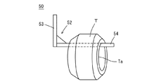
図4は従来のグリーンタイヤ運搬・保持装置を模式的に示す斜視図である。図4に示すように、このグリーンタイヤ運搬・保持装置50は、支柱53とグリーンタイヤ受け軸54とから構成される略L字形のフック52をグリーンタイヤTのビード内周面Taに引っ掛けることによりグリーンタイヤTを吊り下げた状態で運搬して保持する所謂吊り下げ式の運搬・保持装置である。
FIG. 4 is a perspective view schematically showing a conventional green tire carrying / holding device. As shown in FIG. 4, the green tire carrying /
このような吊り下げ式のグリーンタイヤ運搬・保持装置50は、空間を有効に利用することができると共に導入コストが安価であるという利点を有している。
Such a suspension-type green tire carrying /
しかしながら、従来の吊り下げ式の運搬・保持装置では、吊り下げられたグリーンタイヤを保持する時間が長くなるに従って、グリーンタイヤの自重によりグリーンタイヤが変形する恐れがある。このようなグリーンタイヤの変形は、加硫後のタイヤのユニフォミティ(均一性)を悪化させ、走行中の振動や騒音を招く大きな原因となる。そして、特に、STサイズのタイヤなどの重量が大きなタイヤではこのような変形が生じ易い。 However, in the conventional suspension-type transport / holding device, the green tire may be deformed by its own weight as the time for holding the suspended green tire becomes longer. Such deformation of the green tire deteriorates the uniformity (uniformity) of the tire after vulcanization, and becomes a major cause of vibration and noise during traveling. Such deformation is likely to occur particularly in a tire having a large weight such as an ST size tire.
そこで、このような自重によるグリーンタイヤの変形を防止するために、従来より、吊り下げられたグリーンタイヤを作業者が手作業で回転させて、自重が一点に掛からないようにするという対策が採られていたが、多大な作業ロスの発生を招く。 Therefore, in order to prevent such deformation of the green tire due to its own weight, conventionally, a measure has been taken that the suspended green tire is manually rotated by an operator so that the weight is not applied to one point. However, it causes a great loss of work.
本発明は、上記の問題に鑑み、重量が大きなタイヤを吊り下げて運搬・保持しても、自重による変形の発生を抑制することができるグリーンタイヤ運搬・保持装置を提供することを課題とする。 In view of the above problems, an object of the present invention is to provide a green tire transportation / holding device that can suppress the occurrence of deformation due to its own weight even when a heavy tire is suspended and transported / held. .
本発明者は、上記の課題を解決するため鋭意検討を行った結果、以下に記載する発明により上記の課題が解決できることを見出し、本発明を完成させるに至った。 As a result of intensive studies to solve the above problems, the present inventor has found that the above problems can be solved by the invention described below, and has completed the present invention.
請求項1に記載の発明は、
グリーンタイヤを加硫機近傍まで運搬して保持するグリーンタイヤ運搬・保持装置であって、
鉛直方向に延びる支柱と、一端が前記支柱に取り付けられて水平方向に延びるグリーンタイヤ受け軸とから構成されており、前記グリーンタイヤ受け軸の他端側から前記グリーンタイヤを挿入して前記グリーンタイヤ受け軸に引っ掛けることにより、前記グリーンタイヤを吊り下げて保持する略L字形のフックと、
前記略L字形のフックのグリーンタイヤ受け軸を回転させるための回転機構と、
横断面の形状が凹型であり、前記凹型の開口部を上方に配置した状態で前記グリーンタイヤ受け軸を囲うように配置されたカバーと、
前記カバーを上方に向かって付勢する付勢部材と
を備えていることを特徴とするグリーンタイヤ運搬・保持装置である。
The invention described in claim 1
A green tire transporting / holding device that transports and holds a green tire to the vicinity of the vulcanizer,
The green tire includes a pillar extending in the vertical direction and a green tire bearing shaft having one end attached to the pillar and extending in the horizontal direction. The green tire is inserted from the other end side of the green tire bearing shaft. A substantially L-shaped hook for hanging and holding the green tire by being hooked on a receiving shaft;
A rotation mechanism for rotating the green tire bearing shaft of the substantially L-shaped hook;
A cover having a concave cross-sectional shape, and a cover disposed so as to surround the green tire bearing shaft in a state where the concave opening is disposed above;
A green tire carrying / holding device comprising a biasing member that biases the cover upward.
請求項2に記載の発明は、
前記グリーンタイヤ受け軸の、前記支柱と前記グリーンタイヤが挿入される前記他端との間の長さが、0.5〜2.0mであることを特徴とする請求項1に記載のグリーンタイヤ運搬・保持装置である。
The invention described in claim 2
The green tire according to claim 1, wherein a length of the green tire bearing shaft between the support column and the other end into which the green tire is inserted is 0.5 to 2.0 m. It is a transport / holding device.
請求項3に記載の発明は、
前記グリーンタイヤ受け軸の表面に滑り止め加工が施されていることを特徴とする請求項1または請求項2に記載のグリーンタイヤ運搬・保持装置である。
The invention according to claim 3
The green tire carrying / holding device according to claim 1 or 2, wherein the surface of the green tire receiving shaft is anti-slip processed.
請求項4に記載の発明は、
前記滑り止め加工がローレット加工であることを特徴とする請求項3に記載のグリーンタイヤ運搬・保持装置である。
The invention according to claim 4
The green tire carrying / holding device according to claim 3, wherein the anti-slip process is a knurling process.
請求項5に記載の発明は、
前記カバーの前記グリーンタイヤが挿入される側の端部に、上方に延びる板状のストッパーが設けられていることを特徴とする請求項1ないし請求項3のいずれか1項に記載のグリーンタイヤ運搬・保持装置である。
The invention described in claim 5
The green tire according to any one of claims 1 to 3, wherein a plate-like stopper extending upward is provided at an end of the cover on a side where the green tire is inserted. It is a transport / holding device.
本発明によれば、重量が大きなタイヤを吊り下げて運搬・保持しても、自重による変形の発生を抑制することができるグリーンタイヤ運搬・保持装置を提供することができる。 According to the present invention, it is possible to provide a green tire carrying / holding device that can suppress the occurrence of deformation due to its own weight even when a heavy tire is suspended and carried / held.
1.発明に至る経緯
本発明者は、重量が大きなタイヤを吊り下げて運搬・保持しても、自重による変形の発生を抑制することができるグリーンタイヤ運搬・保持装置として、まず、図1に示すようなグリーンタイヤ運搬・保持装置を作製した。
1. 1. Background of the Invention As shown in FIG. 1, the inventor as a green tire transporting / holding device that can suppress the occurrence of deformation due to its own weight even when a heavy tire is suspended and transported / held. A green tire carrying / holding device was produced.
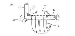
図1は本発明に至る経緯で作製したグリーンタイヤ運搬・保持装置を示す斜視図である。このグリーンタイヤ運搬・保持装置10は、従来と同様に、鉛直方向に延びる支柱13と、一端が支柱13に取り付けられて水平方向に延びるグリーンタイヤ受け軸14とから構成される略L字形のフック12を備えているが、このグリーンタイヤ受け軸14をモーター40により回転させる回転機構をさらに備えている点で従来と異なっている。
FIG. 1 is a perspective view showing a green tire carrying / holding device manufactured in the course of the present invention. The green tire carrying /
このグリーンタイヤ運搬・保持装置10では、略L字形のフック12のグリーンタイヤ受け軸14にグリーンタイヤTのビード内周面Taを引っ掛けてグリーンタイヤTを吊り下げた状態で、モーター40によりグリーンタイヤ受け軸14を回転させる。そして、吊り下げられたグリーンタイヤTがグリーンタイヤ受け軸14の回転に伴って回転することによりグリーンタイヤTの自重が一点に掛かることがなくなるため、自重によるグリーンタイヤTの変形を作業者の手を借りることなく抑制することができる。
In the green tire carrying /
このように、図1に示すグリーンタイヤ運搬・保持装置10を用いることにより、吊り下げた状態でグリーンタイヤを保持していても、作業ロスを生じさせることなく自重による変形を抑制することができるようになるが、このような構成のグリーンタイヤ運搬・保持装置10を採用した場合、新たな問題が発生する恐れがあることが分かった。
Thus, by using the green tire carrying /
即ち、図1のグリーンタイヤ運搬・保持装置10のグリーンタイヤ受け軸14にグリーンタイヤTを引っ掛ける際、グリーンタイヤTの回転中心がグリーンタイヤ受け軸14と平行でなくずれていると、グリーンタイヤTのビード内周面Taに抵抗が掛かった状態でグリーンタイヤTが回転することになり、ビード内周面Taが損傷する恐れがあることが分かった。
That is, when the green tire T is hooked on the green
そこで、本発明者は、グリーンタイヤの軸中心がずれた状態でグリーンタイヤ受け軸に引っ掛けられた場合でも、グリーンタイヤを抵抗が掛からない状態で回転させることができるグリーンタイヤ運搬・保持装置について、さらに実験、検討を重ねた結果、本発明を完成させるに至った。 Therefore, the present inventor is a green tire carrying and holding device that can rotate the green tire without applying resistance even when it is hooked on the green tire receiving shaft with the axis center of the green tire shifted. As a result of further experiments and examinations, the present invention has been completed.
2.本実施の形態に係るグリーンタイヤ運搬・保持装置
以下、本発明の一実施の形態に係るグリーンタイヤ運搬・保持装置について説明する。
2. Hereinafter, a green tire carrying / holding device according to an embodiment of the present invention will be described.
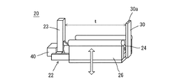
図2は本実施の形態に係るグリーンタイヤ運搬・保持装置を示す斜視図であり、図3は本実施の形態に係るグリーンタイヤ運搬・保持装置の動作を説明する図である。 FIG. 2 is a perspective view showing the green tire carrying / holding device according to the present embodiment, and FIG. 3 is a diagram for explaining the operation of the green tire carrying / holding device according to the present embodiment.
図2に示すように、本実施の形態に係るグリーンタイヤ運搬・保持装置20は、鉛直方向に延びる支柱23と、一端が支柱23に取り付けられて水平方向に延びるグリーンタイヤ受け軸24とから構成される略L字形のフック22を備え、グリーンタイヤ受け軸24をモーター40により回転させる回転機構をさらに備えている点においては、図1に示すグリーンタイヤ運搬・保持装置と同様である。
As shown in FIG. 2, the green tire carrying /
しかし、本実施の形態に係るグリーンタイヤ運搬・保持装置20には、図1に示すグリーンタイヤ運搬・保持装置とは異なり、横断面の形状が凹型で、開口部を上にしてグリーンタイヤ受け軸24を囲うように配置されたカバー26がさらに設けられている。
However, the green tire carrying /
このカバー26は上下に昇降可能であり、付勢部材であるダンパー(図示省略)によって上方に向かって付勢されており、グリーンタイヤを保持していない状態では、カバー26の両側部26aの上端がグリーンタイヤ受け軸24よりも上方に位置するように構成されている。
The
そして、本実施の形態に係るグリーンタイヤ運搬・保持装置20の略L字形のフック22にグリーンタイヤTを引っ掛けて吊り下げる場合、図3に示すように、まず、カバー26の両側部26aの上端にグリーンタイヤTのビード内周面Taが接触する。
When the green tire T is hooked and hung on the substantially L-
このとき、カバー26はダンパーによって上方に付勢されているため、グリーンタイヤTは自重によりカバー26を下方に向けて押圧しながら、緩やかに下降してグリーンタイヤ受け軸24に接触する。このように緩やかに下降する間に、グリーンタイヤTの位置が適切に修正されて、グリーンタイヤTが略L字形のフック22(図2参照)のグリーンタイヤ受け軸24に引っ掛けられる。この結果、グリーンタイヤTの軸中心とグリーンタイヤ受け軸24がずれを生じることなく接触され、グリーンタイヤ受け軸24を回転させてもグリーンタイヤTのビード内周面Taに損傷が生じることがない。
At this time, since the
なお、グリーンタイヤ受け軸24の長さtは、吊り下げられたグリーンタイヤTが落下しない長さに設定され、周辺の機器との関係を考慮すると、0.5〜2.0mであることが好ましく、1.5m程度がより好ましい。
In addition, the length t of the green
そして、グリーンタイヤ受け軸24の表面には滑り止め加工が施されていることが好ましい。滑り止め加工を施すことにより、回転するグリーンタイヤ受け軸24と回転するグリーンタイヤTとの間に滑りが生じることを抑制することができる。このような滑り止め加工としてはローレット加工が好ましい。
And it is preferable that the surface of the green
また、カバー26には、図2に示すように、グリーンタイヤの落下防止用のストッパー30が設けられていることが好ましい。このストッパー30は、カバー26のグリーンタイヤが挿入される側の端部に設けられた上方に延びる板状の部材である。このストッパー30は、カバー26が最も下降したときでも上端30aがグリーンタイヤ受け軸24の上方に位置するように鉛直方向の長さが設定されており、これにより回転中のグリーンタイヤがグリーンタイヤ受け軸24から落下することを防止できる。
Further, as shown in FIG. 2, the
以上のように、本実施の形態においては、グリーンタイヤ受け軸に引っ掛けて吊り下げられたグリーンタイヤを、グリーンタイヤ受け軸の回転に合わせて回転させて保持しているため、保持中も自重が一点に掛からず自重による変形の発生を抑制することができ、さらに、グリーンタイヤのビード内周面に損傷が生じることがない。 As described above, in the present embodiment, the green tire that is hooked and suspended from the green tire bearing shaft is held by rotating in accordance with the rotation of the green tire bearing shaft. The occurrence of deformation due to its own weight can be suppressed without being applied to a single point, and further, the bead inner peripheral surface of the green tire is not damaged.
以下、実施例に基づいて本発明をより具体的に説明する。 Hereinafter, based on an Example, this invention is demonstrated more concretely.
1.実施例および比較例
(1)実施例
成形後のグリーンタイヤT(タイヤサイズ:285/50R20 112V PT2A)を上記した実施の形態におけるグリーンタイヤ運搬・保持装置20の略L字形のフック22に吊り下げ、グリーンタイヤ受け軸24によってグリーンタイヤTを回転させながら30分保持した。
1. Example and Comparative Example (1) Example A green tire T after molding (tire size: 285 / 50R20 112V PT2A) is suspended from a substantially L-shaped
(2)比較例
図4に示すような、グリーンタイヤ受け軸54が固定された従来のグリーンタイヤ運搬・保持装置50の略L字形のフック22にグリーンタイヤTを吊り下げたことを除いて、実施例と同じ条件でグリーンタイヤTを30分保持した。
(2) Comparative Example As shown in FIG. 4, except that the green tire T is suspended from the substantially L-shaped
2.評価
(1)グリーンタイヤの変形
実施例および比較例のそれぞれにおいて、30分保持した後のグリーンタイヤTの寸法を測定し自重による変形の程度を評価した(n=5)。
2. Evaluation (1) Green Tire Deformation In each of the examples and comparative examples, the size of the green tire T after being held for 30 minutes was measured to evaluate the degree of deformation due to its own weight (n = 5).
具体的には、図5に示すように、グリーンタイヤTの水平方向の外径Aと垂直方向の外径Bを測定すると共に、水平方向のビード内径aと垂直方向のビード内径bを測定した。そして、水平方向の外径Aと垂直方向の外径Bとの差(A−B)と、水平方向のビード内径aと垂直方向のビード内径bとの差(a−b)を算出し、算出結果に基づいてグリーンタイヤの変形の程度を評価した。結果を表1に示す。 Specifically, as shown in FIG. 5, the horizontal outer diameter A and the vertical outer diameter B of the green tire T were measured, and the horizontal bead inner diameter a and the vertical bead inner diameter b were measured. . Then, the difference between the horizontal outer diameter A and the vertical outer diameter B (A−B) and the difference between the horizontal bead inner diameter a and the vertical bead inner diameter b (ab) are calculated, The degree of deformation of the green tire was evaluated based on the calculation result. The results are shown in Table 1.
(2)ユニフォミティの評価
30分保持した後のグリーンタイヤTを加硫成形して、加硫後のタイヤのRFV(ラジアルフォースバリエーション)を測定し、その平均値と標準偏差を算出した(n=100)。算出結果を表1に示す。
(2) Evaluation of uniformity Green tire T after being held for 30 minutes was vulcanized, RFV (radial force variation) of the vulcanized tire was measured, and the average value and standard deviation were calculated (n = 100). The calculation results are shown in Table 1.
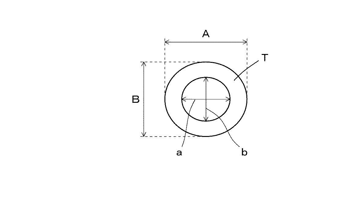
表1より、比較例では、グリーンタイヤ外径およびグリーンタイヤビード内径の何れにおいても、水平方向の寸法と垂直方向の寸法の差が大きくなっており、グリーンタイヤが自重により楕円形に変形していることが分かる。一方、実施例では、水平方向の寸法と垂直方向の寸法の差が小さく、自重による変形が抑制されていることが分かる。 From Table 1, in the comparative example, in both the green tire outer diameter and the green tire bead inner diameter, the difference between the horizontal dimension and the vertical dimension is large, and the green tire is deformed into an oval shape by its own weight. I understand that. On the other hand, in the example, it can be seen that the difference between the horizontal dimension and the vertical dimension is small, and deformation due to its own weight is suppressed.
また、表1より、RFVの平均値、標準偏差の何れにおいても、実施例の方が比較例よりも低い値になっており、ユニフォミティに優れたタイヤが製造されていることが確認できた。 Further, from Table 1, in both the average value and the standard deviation of RFV, the example was lower than the comparative example, and it was confirmed that a tire excellent in uniformity was manufactured.
以上より、実施例のように、略L字形のフック22に吊り下げられたグリーンタイヤを回転させることにより、グリーンタイヤTの変形を抑制して加硫後のタイヤのユニフォミティの低下を防止できることが確認できた。
From the above, by rotating the green tire suspended from the substantially L-shaped
また、保持を行った後のグリーンタイヤTを目視にて確認した結果、ビード内周面Taに損傷は見られず、ダンパーにより緩やかに下降するカバー26でグリーンタイヤ受け軸24を囲うことにより、グリーンタイヤの回転中心とグリーンタイヤ受け軸24との間にずれが生じることなくグリーンタイヤを接触させて、グリーンタイヤ受け軸24の回転によるグリーンタイヤの損傷を適切に防止できていることが確認できた。
In addition, as a result of visually confirming the green tire T after holding, no damage was seen in the bead inner peripheral surface Ta, and by surrounding the green
以上、本発明を実施の形態に基づき説明したが、本発明は上記の実施の形態に限定されるものではない。本発明と同一および均等の範囲内において、上記の実施の形態に対して種々の変更を加えることが可能である。 As mentioned above, although this invention was demonstrated based on embodiment, this invention is not limited to said embodiment. Various modifications can be made to the above-described embodiment within the same and equivalent scope as the present invention.
10、20、50 グリーンタイヤ運搬・保持装置
12、22、52 略L字形のフック
13、23、53 支柱
14、24、54 グリーンタイヤ受け軸
26 カバー
26a カバーの両側部
30 ストッパー
30a ストッパーの上端
40 モーター
A グリーンタイヤの水平方向の外径
a グリーンタイヤの水平方向のビード内径
B グリーンタイヤの垂直方向の外径
b グリーンタイヤの垂直方向のビード内径
T グリーンタイヤ
t グリーンタイヤ受け軸の長さ
Ta ビード内周面
10, 20, 50 Green tire conveying / holding
Claims (5)
鉛直方向に延びる支柱と、一端が前記支柱に取り付けられて水平方向に延びるグリーンタイヤ受け軸とから構成されており、前記グリーンタイヤ受け軸の他端側から前記グリーンタイヤを挿入して前記グリーンタイヤ受け軸に引っ掛けることにより、前記グリーンタイヤを吊り下げて保持する略L字形のフックと、
前記略L字形のフックのグリーンタイヤ受け軸を回転させるための回転機構と、
横断面の形状が凹型であり、前記凹型の開口部を上方に配置した状態で前記グリーンタ
イヤ受け軸を囲うように配置されたカバーと、
前記カバーを上方に向かって付勢する付勢部材と
を備えていることを特徴とするグリーンタイヤ運搬・保持装置。 A green tire transporting / holding device that transports and holds a green tire to the vicinity of the vulcanizer,
The green tire includes a pillar extending in the vertical direction and a green tire bearing shaft having one end attached to the pillar and extending in the horizontal direction. The green tire is inserted from the other end side of the green tire bearing shaft. A substantially L-shaped hook for hanging and holding the green tire by being hooked on a receiving shaft;
A rotation mechanism for rotating the green tire bearing shaft of the substantially L-shaped hook;
A cover having a concave cross-sectional shape, and a cover disposed so as to surround the green tire bearing shaft in a state where the concave opening is disposed above;
A green tire carrying / holding device comprising a biasing member that biases the cover upward.
Priority Applications (1)
| Application Number | Priority Date | Filing Date | Title |
|---|---|---|---|
| JP2015103953A JP6498526B2 (en) | 2015-05-21 | 2015-05-21 | Green tire transport / holding device |
Applications Claiming Priority (1)
| Application Number | Priority Date | Filing Date | Title |
|---|---|---|---|
| JP2015103953A JP6498526B2 (en) | 2015-05-21 | 2015-05-21 | Green tire transport / holding device |
Publications (2)
| Publication Number | Publication Date |
|---|---|
| JP2016215515A JP2016215515A (en) | 2016-12-22 |
| JP6498526B2 true JP6498526B2 (en) | 2019-04-10 |
Family
ID=57577613
Family Applications (1)
| Application Number | Title | Priority Date | Filing Date |
|---|---|---|---|
| JP2015103953A Expired - Fee Related JP6498526B2 (en) | 2015-05-21 | 2015-05-21 | Green tire transport / holding device |
Country Status (1)
| Country | Link |
|---|---|
| JP (1) | JP6498526B2 (en) |
Family Cites Families (6)
| Publication number | Priority date | Publication date | Assignee | Title |
|---|---|---|---|---|
| JPS5537380Y2 (en) * | 1975-05-14 | 1980-09-02 | ||
| JPS5537381Y2 (en) * | 1977-06-20 | 1980-09-02 | ||
| JPS62256613A (en) * | 1986-05-01 | 1987-11-09 | Bridgestone Corp | Method and device for coating tires |
| US6298998B1 (en) * | 1998-07-06 | 2001-10-09 | Bridgestone/Firestone Inc. | Supportive pin rack for green tire storage |
| JP2008143114A (en) * | 2006-12-13 | 2008-06-26 | Sumitomo Rubber Ind Ltd | Green tire rotating device |
| JP2010052266A (en) * | 2008-08-28 | 2010-03-11 | Bridgestone Corp | Raw tire holder and method of manufacturing pneumatic tire |
-
2015
- 2015-05-21 JP JP2015103953A patent/JP6498526B2/en not_active Expired - Fee Related
Also Published As
| Publication number | Publication date |
|---|---|
| JP2016215515A (en) | 2016-12-22 |
Similar Documents
| Publication | Publication Date | Title |
|---|---|---|
| KR101452685B1 (en) | Tray for Transporting Vehicle's Wheel | |
| JP6005276B2 (en) | Tire conveyance method, tire conveyance fixing device, and tire inspection system | |
| JP6454220B2 (en) | Green tire transport / holding device | |
| JP6498526B2 (en) | Green tire transport / holding device | |
| CN204214657U (en) | A kind of can the tyre detecting equipment of automatic loading and unloading wheel rim | |
| US10350844B2 (en) | Green tire support device and method of removing drum from green tire | |
| JP6187889B2 (en) | Tire inspection device and tire attitude detection method | |
| JP5705762B2 (en) | Tire vulcanizer and tire vulcanizer | |
| JP5960441B2 (en) | Raw cover transport device | |
| US20070023966A1 (en) | Tire bead stretcher and method for holding a green tire | |
| JP4375822B2 (en) | Unvulcanized tire reversing device | |
| JP2016210086A (en) | Loader for tire vulcanizer and method of carrying green tire | |
| JP2014133385A (en) | Apparatus and method for transporting tire | |
| JP2012030396A (en) | Tire storing apparatus and storing tire method | |
| JP6794785B2 (en) | Tire transport device | |
| JP2020093871A (en) | Hitch suspension tool and long article conveyance device | |
| JP6442972B2 (en) | Bead separator conveying method and apparatus | |
| KR100549725B1 (en) | Green tire transport apparatus | |
| JP2007062501A (en) | Fixture for conveying pneumatic tire/support body assembly | |
| JP6375856B2 (en) | Method and apparatus for suspending and holding bead separator | |
| JP2016215513A (en) | Green tire mounting base | |
| JP2016036921A (en) | Vertical loader, and transfer method of green tire using the vertical loader | |
| JP2016074129A (en) | Bead member conveying method and device | |
| JP2019055503A (en) | Raw cover centering device, and centering method | |
| JP2019115976A (en) | Air tire manufacturing method and loader |
Legal Events
| Date | Code | Title | Description |
|---|---|---|---|
| A621 | Written request for application examination |
Free format text: JAPANESE INTERMEDIATE CODE: A621 Effective date: 20180314 |
|
| A131 | Notification of reasons for refusal |
Free format text: JAPANESE INTERMEDIATE CODE: A131 Effective date: 20181217 |
|
| A977 | Report on retrieval |
Free format text: JAPANESE INTERMEDIATE CODE: A971007 Effective date: 20181219 |
|
| A521 | Request for written amendment filed |
Free format text: JAPANESE INTERMEDIATE CODE: A523 Effective date: 20190131 |
|
| TRDD | Decision of grant or rejection written | ||
| A01 | Written decision to grant a patent or to grant a registration (utility model) |
Free format text: JAPANESE INTERMEDIATE CODE: A01 Effective date: 20190218 |
|
| A61 | First payment of annual fees (during grant procedure) |
Free format text: JAPANESE INTERMEDIATE CODE: A61 Effective date: 20190313 |
|
| R150 | Certificate of patent or registration of utility model |
Ref document number: 6498526 Country of ref document: JP Free format text: JAPANESE INTERMEDIATE CODE: R150 |
|
| LAPS | Cancellation because of no payment of annual fees |