JP6498075B2 - Overhang passage of steel structure - Google Patents
Overhang passage of steel structure Download PDFInfo
- Publication number
- JP6498075B2 JP6498075B2 JP2015162758A JP2015162758A JP6498075B2 JP 6498075 B2 JP6498075 B2 JP 6498075B2 JP 2015162758 A JP2015162758 A JP 2015162758A JP 2015162758 A JP2015162758 A JP 2015162758A JP 6498075 B2 JP6498075 B2 JP 6498075B2
- Authority
- JP
- Japan
- Prior art keywords
- hook
- cantilever
- steel structure
- stand
- scaffold
- Prior art date
- Legal status (The legal status is an assumption and is not a legal conclusion. Google has not performed a legal analysis and makes no representation as to the accuracy of the status listed.)
- Active
Links
- 229910000831 Steel Inorganic materials 0.000 title claims description 50
- 239000010959 steel Substances 0.000 title claims description 50
- 238000003780 insertion Methods 0.000 claims description 3
- 230000037431 insertion Effects 0.000 claims description 3
- 238000009434 installation Methods 0.000 description 12
- 239000000463 material Substances 0.000 description 9
- 239000000725 suspension Substances 0.000 description 7
- 230000003014 reinforcing effect Effects 0.000 description 6
- 238000009408 flooring Methods 0.000 description 4
- 238000000034 method Methods 0.000 description 4
- 238000005452 bending Methods 0.000 description 3
- XEEYBQQBJWHFJM-UHFFFAOYSA-N Iron Chemical compound [Fe] XEEYBQQBJWHFJM-UHFFFAOYSA-N 0.000 description 2
- 238000010586 diagram Methods 0.000 description 2
- 230000002787 reinforcement Effects 0.000 description 2
- 239000000758 substrate Substances 0.000 description 2
- 239000012141 concentrate Substances 0.000 description 1
- 230000000694 effects Effects 0.000 description 1
- 230000001747 exhibiting effect Effects 0.000 description 1
- 238000011900 installation process Methods 0.000 description 1
- 229910052742 iron Inorganic materials 0.000 description 1
- 239000002184 metal Substances 0.000 description 1
- 229910052751 metal Inorganic materials 0.000 description 1
Images


Landscapes
- Bridges Or Land Bridges (AREA)
- Revetment (AREA)
Description
本発明は仮橋、仮桟橋、構台等の仮設鉄骨構造物または本設鉄骨構造物の側方に拡張して設ける張出通路に関するものである。 The present invention relates to a temporary steel structure such as a temporary bridge, a temporary pier, a gantry or the like, or an overhanging passage provided to be extended to the side of the main steel structure.
クローラクレーン等の大型重機を用いて仮橋、仮桟橋を施工することは周知である(特許文献1,2)。
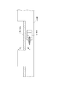
図9を参照して説明すると、狭い幅員の床板a上でクローラクレーン等の重機bが縦架設作業を行う際に、重機bの幅員が床板aの幅員の大半を占めてしまい、作業員等の通行が阻害される場合がある。
このような場合には既設の床板aの側方に覆工板製の張出床板cを増設して作業員の通路や退避領域を確保する必要がある。張出床板cの増設にあたり、張出床板cの支持手段が問題となる。
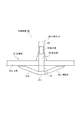
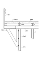
図10を参照して張出床板cの支持手段について説明する。
同図は前提となる仮桟橋の側端部の断面を示すもので、仮桟橋は橋脚である複数の鋼柱dと、これらの鋼柱dの上部に横架した枕材eと、主桁fを介して枕材eの上部を覆う覆工板製の床板aとを有している。
従来は、剛性の方杖gを用いて張出床板cの下面を支持することが現場で行われている。
方杖gは、その垂直部を挟締金具やボルト等の連結具hを用いて最外端の鋼柱dの側面に固定するとともに、方杖gに張出床板cを支承させて既設の床板aを側方に拡張する。なお、符号iは張出床板cの側端に立設した高欄である。
It is well known to construct temporary bridges and temporary piers using large heavy machinery such as crawler cranes (Patent Documents 1 and 2).
Referring to FIG. 9, when a heavy machine b such as a crawler crane performs a vertical installation work on a floor board a having a narrow width, the width of the heavy machine b occupies most of the width of the floor board a. May be obstructed.
In such a case, it is necessary to add an overhanging floor board c made of a lining board to the side of the existing floor board a to secure a worker's passage and retreat area. When the extended floor board c is added, the support means for the extended floor board c becomes a problem.
The support means of the extended floor board c is demonstrated with reference to FIG.
This figure shows the cross section of the side end of the temporary pier, which is a premise. The temporary pier has a plurality of steel columns d that are piers, a pillow material e that is laid horizontally on these steel columns d, and a main girder. It has the floor board a made of a lining board which covers the upper part of the pillow material e through f.
Conventionally, supporting the lower surface of the extended floor board c using a rigid wand g has been performed in the field.
The cane g is fixed to the side surface of the steel column d at the outermost end by using a connecting tool h such as a clamp or a bolt, and the overhanging floor plate c is supported on the cane g. The floor board a is expanded to the side. In addition, the code | symbol i is the handrail erected at the side end of the overhanging floor board c.
既述した従来技術はつぎの問題点を有する。
<1>鋼柱dの全高が数十mにもおよぶような長尺の場合には、方杖gを地組しておくことができないだけでなく、方杖gを既設の床板a上から取り付けることもできない。
方杖gの固定作業を行うには、方杖gの直下に別途の作業足場を設置する必要があり、作業足場の設置と解体撤去に多くのコストと時間を要する。
<2>方杖gを鋼柱dに固定するには、方杖gを吊り込んで取付位置に誘導した後、複数の連結具hを手作業で組み付ける必要があり、方杖gの固定作業に多くの手数と時間がかかる。方杖gを解体撤去する場合も同様に多くの手数と時間がかかる。
<3>方杖gの取り付けや解体は危険な高所作業となるため、安全性の確保が問題となる。
<4>張出床板cを増設するには、重量構造物である方杖gと張出床板cの単品をクレーンで吊り込んで固定する吊り込み作業と固定作業を繰り返し行う必要があるために、クレーンの占用時間が長くなって張出床板cの増設コストが高くつく。
<5>方杖を用いずに張出床板を増設する他の手段として、床板の側方に間隔を隔てて複数の吊上用支柱を立設し、各吊上用支柱の頭部と水平に配置した張出床板の外端部との間に斜めに吊り材を接続して吊り上げ支持する形態も考えられる。
張出床板を吊り材で吊り上げ支持する形態では、吊用支柱の高さが張出床板の幅員以上の高さとなるため、背の高い吊用支柱が障害物となるだけでなく、張出床板の上方を斜めに横断する吊り材も通行の邪魔になる。
The prior art described above has the following problems.
<1> In the case where the total height of the steel column d is several tens of meters, not only the brace g can not be grounded but also the brace g can be removed from the existing floor board a. It cannot be installed.
In order to perform the fixing work of the cane g, it is necessary to install a separate work scaffold immediately below the cane g, and much cost and time are required for installing and dismantling the work scaffold.
<2> In order to fix the cane g to the steel column d, it is necessary to manually assemble a plurality of couplers h after the cane g is suspended and guided to the mounting position. It takes a lot of work and time. Similarly, it takes a lot of work and time to dismantle and remove the cane g.
<3> Since the installation and disassembly of the wand g is a dangerous work at a high place, ensuring safety is a problem.
<4> In order to increase the extended floor board c, it is necessary to repeatedly perform the hanging work and the fixing work for hanging and fixing a single piece of the wand g and the extended floor board c, which are heavy structures, with a crane. The crane occupancy time becomes longer and the extension cost of the extended floor plate c is high.
<5> As another means of adding an extended floor board without using a cane, a plurality of lifting pillars are erected on the side of the floor board at intervals, and horizontally with the head of each lifting pillar. A form in which a suspension member is connected obliquely between the outer end portions of the overhanging floor plates arranged on the floor and supported by lifting is also conceivable.
In the form in which the extended floor board is lifted and supported by the suspension material, the height of the suspension column becomes higher than the width of the extended floor plate, so that the tall suspension column not only becomes an obstacle, but also the extended floor plate Hanging material that crosses diagonally above the door also obstructs traffic.
本発明は以上の点に鑑みて成されたもので、その目的とするところは、別途の作業足場、方杖等を用いずに片持足場の設置および撤去を安全で短時間に行える張出通路を提供することにある。 The present invention has been made in view of the above points. The object of the present invention is to provide an overhang capable of installing and removing a cantilevered scaffold safely and in a short time without using a separate work scaffold or a cane. To provide a passage.
本発明は、床板を敷設した鉄骨構造物の最上位の桁材の側方に増設する張出通路であって、一側に複数の切欠を形成した足場板と、該足場板の切欠に面して上向きに突設した鉤形を呈する複数の片持フックとを有する片持足場と、最外側の桁材に立設し、前記片持フックと嵌合可能な複数のフックスタンドとを具備し、前記フックスタンドが具備する嵌合部と、前記片持フックが具備する嵌合部とを嵌合させて前記片持足場を鉄骨構造物の桁材に片持ちで支持させたことを特徴とする。
本発明の他の形態において、前記片持フックに当接させたフックスタンドの上端部および中間部の二つの当接部を介して片持足場をフックスタンドに片持ちで支持させる。
本発明の他の形態において、前記フックスタンドは、前記最外側の桁材の外方へ向けて傾斜する傾斜部と、該傾斜部の先端から鉛直に向けて延設し、片持フックの挿嵌部と嵌合可能な嵌合部とを具備する。
本発明の他の形態において、前記最外側の桁材と片持フックの起立部との間に間隙を形成するように、前記フックスタンドが略く字形を呈する。
本発明の他の形態において、足場板の切欠が前記フックスタンドを収容可能な開口幅であり、該切欠内に収容したフックスタンドが切欠空間を閉鎖する寸法関係にある。
本発明の他の形態において、前記片持フックは足場板を横断する横断部と、横断部の一端から真上に延設した起立部と、起立部の一端から水平に延設した水平部と、水平部の端部から真下に延設した嵌合部とを有する。
本発明の他の形態において、切欠を介して足場板の上方へ突出する片持フックの起立部の突出長が、前記フックスタンドおよび片持フックが具備する両嵌合部を嵌合させたときに、足場板の上面が該足場板と隣り合う鉄骨構造物の床板の上面と面一となる寸法関係にある。
本発明の他の形態において、鉄骨構造物が仮橋、仮桟橋、構台等の仮設鉄骨構造物、または本設鉄骨構造物である。
The present invention is an overhang passage that is added to the side of the uppermost beam of a steel structure laid with a floor board, and a scaffold board having a plurality of cutouts formed on one side thereof, and a surface facing the cutout of the scaffold board. comprising: a cantilever scaffold having a plurality of cantilever hooks standing on the outermost spar, and a plurality of hooks stand fittable with the cantilever hooks exhibiting hook which projects upwards by In addition, the cantilever scaffold is supported by the girders of the steel structure in a cantilever manner by fitting the fitting portion provided in the hook stand and the fitting portion provided in the cantilever hook. And
In another embodiment of the present invention, the cantilever scaffold is supported by the hook stand in a cantilever manner through the two abutting portions of the upper end portion and the intermediate portion of the hook stand abutted against the cantilever hook.
In another embodiment of the present invention, the hook stand includes an inclined portion that is inclined outwardly of the outermost beam member, and extends vertically from the tip of the inclined portion, and the cantilever hook is inserted. The fitting part and the fitting part which can be fitted are comprised.
In another embodiment of the present invention, the hook stand has a generally square shape so as to form a gap between the outermost beam member and the upright portion of the cantilever hook.
In another embodiment of the present invention, the notch of the scaffold plate has an opening width capable of accommodating the hook stand, and the hook stand accommodated in the notch has a dimensional relationship for closing the notch space.
In another aspect of the present invention, the cantilever hook includes a transverse part that crosses the scaffolding plate, an upright part that extends directly from one end of the transverse part, and a horizontal part that extends horizontally from one end of the upright part. And a fitting portion extending directly below from the end of the horizontal portion.
In another embodiment of the present invention, when the protruding length of the upright portion of the cantilever hook that protrudes upward from the scaffolding plate through the notch is fitted into both the fitting portions of the hook stand and the cantilever hook. In addition, the upper surface of the scaffold plate is in a dimensional relationship with the upper surface of the floor plate of the steel structure adjacent to the scaffold plate.
In another embodiment of the present invention, the steel structure is a temporary steel structure such as a temporary bridge, a temporary pier, a gantry, or a permanent steel structure.
本発明はつぎの効果を奏する。
<1>ユニット化した片持足場を増設現場へクレーンで吊り込むだけの簡単に作業で設置でき、撤去するときもユニット化した片持足場を吊り上げて簡単に撤去できる。
したがって、別途の作業足場や法杖枠等を使用せずに、張出通路の設置および撤去を安全で短時間に行える
<2>クレーンの占用時間を大幅に短縮できて、張出通路の増設コストを低減できる。
<3>床板から突出する片持フックの高さが低いので、他の作業や通行の邪魔にならない。
<4>フックスタンドが高さ方向に距離を隔てた二点で片持足場の荷重を分散して支持できる。
<5>増設した足場板の上面と隣り合う鉄骨構造物の床板の上面との間に段差のないフラットな連続面を形成できる。
The present invention has the following effects.
<1> The unitized cantilever scaffold can be installed simply by hanging it to the expansion site with a crane, and when it is removed, the unitized cantilever scaffold can be easily lifted and removed.
Therefore, installation and removal of the overhanging passage can be done safely and in a short time without using a separate work scaffold or a cane frame. <2> The occupation time of the crane can be greatly reduced, and the extension of the overhanging passage can be increased. Cost can be reduced.
<3> Since the height of the cantilever hook protruding from the floor board is low, it does not interfere with other work or traffic.
<4> The load of the cantilevered scaffold can be dispersed and supported at two points where the hook stand is spaced apart in the height direction.
<5> A flat continuous surface without a step can be formed between the upper surface of the added scaffolding plate and the upper surface of the floor plate of the adjacent steel structure.
以下に図面を参照しながら本発明を詳細に説明する。 Hereinafter, the present invention will be described in detail with reference to the drawings.
<1>鉄骨構造物の張出通路の概要
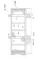
図1に一部を破断した鉄骨構造物40用の張出通路10の全体図を示す。
鉄骨構造物40は最上位の桁材41に覆工板製の床板42が敷設してある例えば仮橋、仮桟橋、構台等の仮設鉄骨構造物または本設鉄骨構造物を含む。
張出通路10は、一側に複数の片持フック50を具備した片持足場30と、鉄骨構造物40の最外側の桁材41に立設した複数のフックスタンド50とにより構成する。
本発明に係るは張出通路10、フックスタンド20が具備する嵌合部55と、片持フック20が具備する嵌合部24とを嵌合させて片持足場30を鉄骨構造物40の最外側の桁材41に片持ちで支持させるように構成したものである。
<1> Outline of Overhanging Passage of Steel Structure FIG. 1 shows an overall view of an overhanging passage 10 for a steel structure 40 with a part thereof broken.
The steel structure 40 includes, for example, a temporary steel structure such as a temporary bridge, a temporary pier, a gantry, or a permanent steel structure in which a floor plate 42 made of a lining plate is laid on an uppermost beam member 41.
The overhang passage 10 includes a cantilever scaffold 30 having a plurality of cantilever hooks 50 on one side, and a plurality of hook stands 50 erected on the outermost beam member 41 of the steel structure 40.
According to the present invention, the cantilever scaffold 30 is made the most of the steel structure 40 by fitting the overhanging passage 10, the fitting portion 55 provided in the
<2>片持足場
図1〜4を参照して説明すると、片持足場30は少なくとも矩形を呈する足場板31と、足場板31の長辺の一側に開設した切欠32に面して上向きに突設した鉤形を呈する複数の片持フック20とを有する。
<2> Cantilever Scaffolding Referring to FIGS. 1 to 4, the cantilevered scaffold 30 faces upward at least to a
<2.1>足場板
足場板31は矩形を呈する剛性枠の上面に床材を設けた組立体である。
図4に例示した足場板31では、平行に配置した主桁31a,31aの間に交差させて複数の横断桁31bを接合して剛性枠を形成した形態を示すが、桁材の配置形態は図示した形態に限定されるものではない。
<2.1> Scaffolding plate The
The
<2.1.1>床材
本例では足場板31の床材としてエキスパンドメタルと滑り止め付き鉄板の組み合せた形態を示すが、床材についても公知の各種素材を適用できる。
<2.1.1> Flooring material In this example, the flooring material of the
<2.1.2>切欠
足場板31の長辺の一側には、片持フック20の配置間隔に合せて複数の切欠32が開設してある。
切欠32は、片持フック20の起立部22およびフックスタンド50の当板53を収容可能な開口幅で開設してある。
<2.1.2> Notch A plurality of
The
<2.1.3>幅木と高欄
足場板31の他側には幅木33と着脱式の高欄34を取り付けておく。
高欄34は予め足場板31に取り付けておいてもよいが、片持足場30の吊り込みの障害となるときは取り外しておき後付けするとよい。
また使途に応じて各種の追加部材を足場板31に付設しておくことも可能である。
<2.1.3> Skirting board and handrail On the other side of the
The
It is also possible to attach various additional members to the
<2.1.4>足場板の補強構造
足場板31の強度が不足する場合は、必要に応じて足場板31を補強する。
図6に例示した補強構造について説明すると、片持フック20の横断部21を中心に主桁31aの間に繋ぎ材31cと一対の補強材31d,31dを架け渡すことで足場板31の曲げ強度を高めることができる。
足場板31を補強することで、吊り込み時における足場板31の撓み変形を抑制して片持ちフック20とフックスタンド50との嵌合を容易にするだけでなく、片持ちフック20およびフックスタンド50の配設ピッチを広げることができる。
<2.1.4> Reinforcement structure of scaffold plate When the strength of the
The reinforcing structure illustrated in FIG. 6 will be described. The bending strength of the
Reinforcing the
<2.2>片持フック
図1〜5を参照して説明すると、片持フック20はフックスタンド50に嵌合させて足場板31を片持ちするための掛止体である。
本例の片持フック20について説明すると、片持フック20は足場板31を横断する横断部21と、横断部21の一端から真上に延設した起立部22と、起立部22の一端から水平に延設した水平部23と、水平部23の端部から真下に延設した凸状の嵌合部24とを有し、これらは複数の鋼材を接合して形成する。
横断部21と起立部22の間はL字形を呈し、起立部22から水平部23と嵌合部24の間は逆U字形(鉤形)を呈する。
嵌合部24には連結ピン56を挿通可能なピン穴が穿設してある。
<2.2> Cantilever Hook If it demonstrates with reference to FIGS. 1-5, the
The
Between the crossing
A pin hole into which the connecting
<2.2.1>片持フックと足場板との関係
片持フック20と足場板31は分離不能な一体構造の関係にある。
本例では横断部21に足場板31を搭載して一体化した形態について示すが、横断部21を省略し、足場板31を構成する剛性枠の一部から起立部22を延設してもよい。
<2.2.1> Relationship between Cantilever Hook and Scaffolding Plate The
In this example, a form in which the
<2.2.2>片持フックの突出長
切欠32を通じて足場板31の上方へ突出する片持フック20の起立部22の突出長は、嵌合部24をフックスタンド50の嵌合部55に嵌合させたとき、足場板31の上面が既設の床板42の上面と面一となる寸法関係にある。
<2.2.2> Protruding length of cantilever hook The protruding length of the upright portion 22 of the
<2.2.3>片持フックの設置数と配置間隔
片持フック20の設置数と配置間隔は、足場板31の平面積と載荷重等を考慮して適宜選択する。
<2.2.3> Number of Cantilever Hooks Installed and Arrangement Interval The number of cantilever hooks 20 installed and the interval between them are appropriately selected in consideration of the flat area of the
<3>フックスタンド
図5を参照して説明すると、フックスタンド50は片持フック20を介して足場板31の一側を吊り下げた状態で、鉄骨構造物40の最外側の桁材41に保持させるための鋼製の支持部材である。
フックスタンド50は、ボルト連結手段等を介して桁材41に対して着脱自在である。
フックスタンド50は全体形状が略「く」の字形を呈していて、最外側の桁材41の外方へ向けて傾斜する傾斜部51と、傾斜部51の先端から鉛直に向けて延設し、片持フック20の挿嵌24と嵌合可能な凹状の嵌合部55とを具備する。
傾斜部51は複数のボルト穴を有する基板52に対して傾斜して固着してある。
<3> Hook Stand Referring to FIG. 5, the hook stand 50 is attached to the outermost beam member 41 of the steel structure 40 in a state where one side of the
The hook stand 50 can be attached to and detached from the beam member 41 via a bolt connecting means or the like.
The hook stand 50 has a substantially “<” shape as a whole, and has an inclined portion 51 that is inclined outwardly from the outermost beam member 41, and extends vertically from the tip of the inclined portion 51. The concave fitting portion 55 that can be fitted to the insertion fitting 24 of the
The inclined portion 51 is fixed to the
<3.1>フックスタンドを屈曲させた理由
フックスタンド50を略く字形に形成したのは、片持フック20の起立部22が最外側の桁材41と干渉せずに、片持フック20およびフックスタンド50の両嵌合部24,55を円滑に嵌合させるためである。
換言すれば、最外側の桁材41と片持フック20の起立部22との間に所定の間隙Gを形成した状態で、片持フック20の凸状の嵌合部24をフックスタンド50の凹状の嵌合部55に嵌合させるためである。
<3.1> Reason for Bending the Hook Stand The hook stand 50 is formed in a substantially square shape because the upright portion 22 of the
In other words, the convex fitting portion 24 of the
<3.2>当板
傾斜部51と凹状の嵌合部55の境界部には水平に向けて矩形の当板53が介装してある。
当板53は傾斜部51および嵌合部55の断面より大形の板体であり、当板53の一部が傾斜部51と嵌合部55の屈曲した外側境界部から外方へ向けて突出している。
当板53は足場板31の切欠32内に収容したときに切欠空間を閉鎖できる寸法関係にある。
<3.2> Abutting Plate A rectangular abutting plate 53 is interposed horizontally at the boundary between the inclined portion 51 and the concave fitting portion 55.
The contact plate 53 is a plate body that is larger than the cross sections of the inclined portion 51 and the fitting portion 55, and a part of the contact plate 53 is directed outward from the bent outer boundary portion of the inclined portion 51 and the fitting portion 55. It protrudes.
The abutment plate 53 has a dimensional relationship that allows the notch space to be closed when accommodated in the
<3.3>補強板
本例では傾斜部51の引張側に補強板54を付設した形態を示すが、補強板54は必須ではない。
<3.3> Reinforcing Plate In this example, the reinforcing plate 54 is provided on the tension side of the inclined portion 51. However, the reinforcing plate 54 is not essential.
<3.4>フックスタンドの高さ
空間の活用性を考慮するとフックスタンド50の高さは低いほど望ましいが、低過ぎると片持足場30の安定支持が難しくなる。
そこで、フックスタンド50の高さは足場板31の幅員より低い寸法とする。
換言すれば、図示した形態におけるフックスタンド50の高さは、例えば既設の床板42の厚さの約2.5倍前後の高さを有する。
また、傾斜部51は、例えば既設の床板42の厚さと同じ高さか、床板42の厚さよりやや低い高さを有する。
嵌合部55の高さは、例えば既設の床板42の厚さの1.5倍前後の高さを有する。
フックスタンド50の全高やフックスタンド50の各部位の高さは上記した例示に限定されず、適宜選択が可能である。
<3.4> Hook Stand Height Considering the utility of space, the height of the hook stand 50 is preferably as low as possible, but if it is too low, stable support of the cantilevered scaffold 30 becomes difficult.
Therefore, the height of the hook stand 50 is set to be lower than the width of the
In other words, the height of the hook stand 50 in the illustrated form has a height of about 2.5 times the thickness of the existing floor plate 42, for example.
The inclined portion 51 has, for example, the same height as the thickness of the existing floor plate 42 or a height slightly lower than the thickness of the floor plate 42.
The height of the fitting part 55 has a height of about 1.5 times the thickness of the existing floor plate 42, for example.
The overall height of the hook stand 50 and the height of each part of the hook stand 50 are not limited to the above examples, and can be appropriately selected.
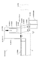
<4>片持フックとフックスタンドの嵌合構造
片持フック20のお嵌合部24はフックスタンド50の嵌合部55にガタツキのない状態で嵌合可能である。
<4> Fitting Structure of Cantilever Hook and Hook Stand The fitting portion 24 of the
<4.1>片持フックとフックスタンドの嵌合部の断面形状
本例では片持フック20およびフックスタンド50の各嵌合部24,55の断面形状が方形を呈する形態について示すが、円形や他の多角形であってもよい。
要は、凸状の嵌合部24,55の何れか一方が嵌合部24,55の何れか他方に嵌挿できる断面形状であればよい。
<4.1> Cross-sectional shape of fitting portion of cantilever hook and hook stand In this example, the cross-sectional shape of each of the fitting portions 24 and 55 of the
The point is that any one of the convex fitting portions 24 and 55 may have a cross-sectional shape that can be inserted into any one of the fitting portions 24 and 55.
<4.2>片持フックとフックスタンドの嵌合部の組み合せについて
本例では片持フック20の嵌合部24を凸状に形成し、フックスタンド50の嵌合部55を凹状(筒状)に形成した組み合せについて説明するが、この組み合わせを逆にして片持フック20の嵌合部24を凹状に形成し、フックスタンド50の嵌合部55を凸状に形成して嵌合させてもよい。
<4.2> Combination of cantilever hook and hook stand fitting portion In this example, the fitting portion 24 of the
[張出通路の設置方法]
つぎに張出通路10の設置方法について説明する。
[Installation method of overhang passage]
Next, a method for installing the overhang passage 10 will be described.
<1>フックスタンドの設置
図7に示すように、鉄骨構造物40の最外側の桁材41の上面に、片持フック20の配置間隔に合せて複数のフックスタンド50を配置し、その基板52をボルト止めして固定する。この際、各フックスタンド50を構成する嵌合部55を既設の床板42から離隔させて固定する。
フックスタンド50の設置にあたり、既設の床板42を利用して設置できるので、鉄骨構造物40の側方に別途の作業足場を設ける必要がない。
<1> Installation of Hook Stand As shown in FIG. 7, a plurality of hook stands 50 are arranged on the upper surface of the outermost beam member 41 of the steel structure 40 in accordance with the arrangement interval of the cantilever hooks 20. Secure 52 with bolts. At this time, the fitting portion 55 constituting each hook stand 50 is fixed apart from the existing floor plate 42.
When the hook stand 50 is installed, it can be installed using the existing floor plate 42, so that it is not necessary to provide a separate work scaffold on the side of the steel structure 40.
<2>片持足場の設置
図1,3に示すように、水平状態を保ったままクレーンで吊り上げた片持足場30を、鉄骨構造物40の側方へ移動して、片持フック20をフックスタンド50に嵌合させることで片持足場30の設置を完了する。
以降に片持足場30の設置工程について詳しく説明する。
<2> Installation of Cantilever Scaffolding As shown in FIGS. 1 and 3, the cantilever scaffold 30 lifted by a crane while keeping the horizontal state is moved to the side of the steel structure 40, and the
Hereinafter, the installation process of the cantilever scaffold 30 will be described in detail.
<2.1>片持足場の吊り込み
足場板31の一側に形成した各片持フック20の嵌合部24を対応する各フックスタンド50の真上に位置させる。
<2.1> Suspension of cantilever scaffold The fitting part 24 of each
<2.2>片持フックとフックスタンドの嵌合
この状態で、片持足場30の全体をゆっくりと降下させて、片持フック20の嵌合部24をフックスタンド50の嵌合部55に差し込んで嵌合させる。
片持足場30を降下させる際、略く字形を呈するフックスタンド50の嵌合部55が桁材41の外方へ張り出ているので、片持フック20の起立部22が桁材41と干渉しないだけでなく、片持フック20の起立部22の外面がガイド面となってフックスタンド50の当板53の側面と摺接するため、両嵌合部24,55の嵌合作業を短時間の間に円滑に行うことができる。
足場板31の切欠32内にフックスタンド50を収容することで、切欠空間の大半が封鎖されるので、面一に形成した足場板31と既設の床板42の上面の間に大きな隙間が生じない。
<2.2> Fitting of cantilever hook and hook stand In this state, the entire cantilever scaffold 30 is slowly lowered, and the fitting part 24 of the
When the cantilever scaffold 30 is lowered, the fitting portion 55 of the hook stand 50 having a substantially square shape protrudes outward from the beam member 41, so that the standing portion 22 of the
By accommodating the hook stand 50 in the
<2.3>連結ピンの挿入
両嵌合部24,55に連結ピン56を差し込んで外れを防止する。
フックスタンド50の嵌合部55の上端面と片持フック20の水平部23の下面との当接面を介してして片持足場30の荷重をフックスタンド50へ伝えるので、連結ピン56に荷重は作用しない。
本発明では、鉄骨構造物40を支える鋼柱の全高が数十mにもおよぶような長尺の場合であっても、鉄骨構造物40の側方に別途の作業足場を設けることなく、一回のクレーン操作で以て鉄骨構造物40の側方に張出通路10を増設できる。
また片持フック20とフックスタンド50の位置合わせ作業も既設の床板42上で安全に行える。
<2.3> Insertion of connecting pin The connecting
Since the load of the cantilever scaffold 30 is transmitted to the hook stand 50 via the contact surface between the upper end surface of the fitting portion 55 of the hook stand 50 and the lower surface of the
In the present invention, even when the total height of the steel column supporting the steel structure 40 is several tens of meters, a separate work scaffold is not provided on the side of the steel structure 40. The overhang passage 10 can be added to the side of the steel structure 40 by one crane operation.
Further, the alignment work between the
<3>片持足場の片持ち支持構造
本発明ではフックスタンド50を介して片持足場30を鉄骨構造物40の桁材41に片持ちで支持する構造である。
図5を参照して片持足場30の片持ち支持構造(片持ち梁)について詳しく説明すると、片持フック20の水平部23の下面とフックスタンド50の上端との間に第1当接部P1が形成され、片持フック20の起立部22の外面とフックスタンド50の当板53の側面との間に第2当接部P2が形成される。第2当接部P2は第1当接部P1の下方に形成される。
片持足場30の重量は、これらの第1および第2当接部P1,P2の二点を通じてフックスタンド50に支持される。
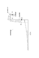
図8に示した片持足場30のモーメント図からも明らかなように、上下の位置関係にある第1および第2当接部P1,P2の二点を通じて支持できるので、片持足場30を安定した姿勢で片持ちできる。
さらに、第1および第2当接部P1,P2間の距離が高さ方向に離れているので、片持フック20だけでなくフックスタンド50に対しても荷重を分散できるので、特定の部位に過大な応力が集中しないで済む。
さらにまた、高さ方向に距離を隔てた二点で片持足場30を支持できるので、片持フック20の突出長を低く抑えることができる。
<3> Cantilever Scaffolding Support Structure of Cantilever Scaffolding In the present invention, the cantilever scaffold 30 is supported by the girders 41 of the steel structure 40 via the hook stand 50 in a cantilevered manner.
The cantilever support structure (cantilever beam) of the cantilever scaffold 30 will be described in detail with reference to FIG. 5. The first abutting portion is provided between the lower surface of the
The weight of the cantilever scaffold 30 is supported by the hook stand 50 through the two points of the first and second contact portions P 1 and P 2 .
As can be seen from the moment diagram of the cantilevered scaffold 30 shown in FIG. 8, the cantilever scaffold 30 can be supported through the two points of the first and second contact portions P 1 and P 2 in the vertical relationship. Can be cantilevered in a stable posture.
Further, since the distance between the first and second contact portions P 1 and P 2 is separated in the height direction, the load can be distributed not only to the
Furthermore, since the cantilever scaffold 30 can be supported at two points spaced apart in the height direction, the protruding length of the
[張出通路の撤去方法]
張出通路10を撤去する場合は、既述した設置方法と逆の作業工程で簡単に行うことができる。
すなわち、連結ピン56を取り除いた状態で張出足場10をクレーンで吊り上げて撤去するだけの簡単な作業で張出通路10を撤去できる。
フックスタンド50は撤去してもよいが、撤去せずに残置させた複数のフックスタンド50間に図示しない高欄用の支柱を差し込んで既設の床板42用の高欄を形成してもよい。
本発明では張出通路10の設置作業だけでなく、張出通路10の撤去作業も安全で、かつ短時間に行える
[How to remove the overhang passage]
In the case of removing the overhang passage 10, it can be easily performed by an operation process reverse to the installation method described above.
In other words, the overhanging passage 10 can be removed by a simple operation of lifting the overhanging scaffold 10 with a crane and removing the connecting
Although the hook stand 50 may be removed, a rail for the existing floor board 42 may be formed by inserting a column for a rail not shown between the plurality of hook stands 50 left without being removed.
In the present invention, not only the installation work of the overhang passage 10 but also the removal work of the overhang passage 10 can be performed safely and in a short time.
[張出通路の転用性について]
本発明に係る張出通路10は、片持フック20の着脱が容易であり、ユニット化した片持足場30の設置と解体が容易である。
したがって、撤去した片持フック20や片持足場30の次工区への転用が簡単に行える。
[About diversion of overhang passage]
In the overhang passage 10 according to the present invention, the cantilever hooks 20 can be easily attached and detached, and the unitized cantilever scaffold 30 can be easily installed and disassembled.
Accordingly, the removed
10・・・張出通路
20・・・片持フック
21・・・片持フックの横断部
22・・・片持フックの起立部
23・・・片持フックの水平部
24・・・片持フックの嵌合部
30・・・片持足場
31・・・足場板
32・・・足場板の切欠
33・・・足場板の幅木
34・・・足場板の高欄
40・・・鉄骨構造物
41・・・鉄骨構造物の桁材
42・・・鉄骨構造物の床板
50・・・フックスタンド
51・・・フックスタンドの傾斜部
52・・・フックスタンドの基板
53・・・フックスタンドの当板
54・・・フックスタンドの補強板
55・・・フックスタンドの嵌合部
56・・・連結ピン
DESCRIPTION OF SYMBOLS 10 ...
Claims (8)
一側に複数の切欠を形成した足場板と、該足場板の切欠に面して上向きに突設した鉤形を呈する複数の片持フックとを有する片持足場と、
最外側の桁材に立設し、前記片持フックと嵌合可能な複数のフックスタンドとを具備し、
前記フックスタンドが具備する嵌合部と、前記片持フックが具備する嵌合部とを嵌合させて前記片持足場を鉄骨構造物の桁材に片持ちで支持させたことを特徴とする、
鉄骨構造物の張出通路。 It is an overhang passage that is added to the side of the uppermost girders of a steel structure laid with floorboards,
A cantilevered scaffold having a scaffolding plate formed with a plurality of notches on one side, and a plurality of cantilevered hooks that project upwardly facing the notches of the scaffolding plate,
Standing on the outermost spar, and a plurality of hooks stand fittable with the cantilever hook,
A fitting portion provided in the hook stand and a fitting portion provided in the cantilever hook are fitted to support the cantilever scaffold on a girder of a steel structure in a cantilever manner. ,
Overhang passage of steel structure.
Priority Applications (1)
| Application Number | Priority Date | Filing Date | Title |
|---|---|---|---|
| JP2015162758A JP6498075B2 (en) | 2015-08-20 | 2015-08-20 | Overhang passage of steel structure |
Applications Claiming Priority (1)
| Application Number | Priority Date | Filing Date | Title |
|---|---|---|---|
| JP2015162758A JP6498075B2 (en) | 2015-08-20 | 2015-08-20 | Overhang passage of steel structure |
Publications (2)
| Publication Number | Publication Date |
|---|---|
| JP2017040113A JP2017040113A (en) | 2017-02-23 |
| JP6498075B2 true JP6498075B2 (en) | 2019-04-10 |
Family
ID=58206425
Family Applications (1)
| Application Number | Title | Priority Date | Filing Date |
|---|---|---|---|
| JP2015162758A Active JP6498075B2 (en) | 2015-08-20 | 2015-08-20 | Overhang passage of steel structure |
Country Status (1)
| Country | Link |
|---|---|
| JP (1) | JP6498075B2 (en) |
Families Citing this family (4)
| Publication number | Priority date | Publication date | Assignee | Title |
|---|---|---|---|---|
| CN108252514B (en) * | 2018-03-23 | 2023-05-26 | 中冶建工集团有限公司 | Construction platform for steel form column |
| JP7300146B2 (en) * | 2019-02-22 | 2023-06-29 | 長谷川工業株式会社 | Installation structure of baseboards on inspection roads and inspection roads |
| CN109958062A (en) * | 2019-04-12 | 2019-07-02 | 北京市政建设集团有限责任公司 | A kind of pier stud construction technology |
| JP7341035B2 (en) * | 2019-11-14 | 2023-09-08 | 東洋建設株式会社 | work equipment |
Family Cites Families (5)
| Publication number | Priority date | Publication date | Assignee | Title |
|---|---|---|---|---|
| JPH05295712A (en) * | 1992-04-15 | 1993-11-09 | Mitsui Eng & Shipbuild Co Ltd | Mobile protecting construction for bridge |
| JPH0614210U (en) * | 1992-07-24 | 1994-02-22 | 石川島播磨重工業株式会社 | Concrete formwork support piece for bridge concrete floor slab construction |
| JP3027130B2 (en) * | 1997-06-30 | 2000-03-27 | ショーボンド建設株式会社 | Assembly structure of hanging scaffold |
| JP3186444U (en) * | 2013-07-25 | 2013-10-03 | 株式会社丸栄機工 | Temporary scaffold |
| JP6138192B2 (en) * | 2015-05-15 | 2017-05-31 | 株式会社高知丸高 | Steel pipe pile construction method |
-
2015
- 2015-08-20 JP JP2015162758A patent/JP6498075B2/en active Active
Also Published As
| Publication number | Publication date |
|---|---|
| JP2017040113A (en) | 2017-02-23 |
Similar Documents
| Publication | Publication Date | Title |
|---|---|---|
| JP6498075B2 (en) | Overhang passage of steel structure | |
| JP3181041U (en) | Mounting member for scaffolding for bridge | |
| KR20150078249A (en) | a cantilever structure of bridge and cantilever construction method | |
| KR101076562B1 (en) | Supporting structure of slab form | |
| JP2008297704A (en) | Brace serving also as handrail | |
| JP7430071B2 (en) | Mobile scaffolding, mobile scaffolding system, and installation method of mobile scaffolding system | |
| JP2012102468A (en) | Movable scaffold for repairing bridge lower face and installation method for the same | |
| KR101168205B1 (en) | Bridge maintenance and administrative passage and constructing method thereof | |
| JP6339986B2 (en) | How to assemble a suspended scaffold using a slide frame | |
| JP2010090676A (en) | Ledger frame with floor, and frame scaffold | |
| KR100373783B1 (en) | A temporary bracket for construction of precast concrete beam bridge and the temporary work method using the same | |
| JP6590512B2 (en) | Staircase temporary scaffolding | |
| KR102464479B1 (en) | Four-way binding bracket of single binding means for hanging bridge inspection facilities | |
| JP5773469B1 (en) | Suspended scaffolding | |
| KR200413590Y1 (en) | Scaffold and construction structure thereof | |
| JP5807883B1 (en) | Suspended scaffolding | |
| JP6491895B2 (en) | Reinforcement frame for temporary structures | |
| JP5378735B2 (en) | Cloth frame with floor and frame scaffold | |
| JP3862707B2 (en) | Construction method of overpass slab and precast concrete plate for overhang slab | |
| JP6520533B2 (en) | Overhead crane support device and load receiving member | |
| JP5386134B2 (en) | Cloth frame with floor and frame scaffold | |
| JP6368628B2 (en) | Mobile scaffold and inspection / repair method using the mobile scaffold | |
| KR100808291B1 (en) | A safety device for pierces | |
| KR200480362Y1 (en) | Folding safety net assembly of gang form | |
| CN113652953A (en) | Novel assembled overline bridge ramp |
Legal Events
| Date | Code | Title | Description |
|---|---|---|---|
| A621 | Written request for application examination |
Free format text: JAPANESE INTERMEDIATE CODE: A621 Effective date: 20180601 |
|
| A977 | Report on retrieval |
Free format text: JAPANESE INTERMEDIATE CODE: A971007 Effective date: 20190118 |
|
| A131 | Notification of reasons for refusal |
Free format text: JAPANESE INTERMEDIATE CODE: A131 Effective date: 20190129 |
|
| A521 | Request for written amendment filed |
Free format text: JAPANESE INTERMEDIATE CODE: A523 Effective date: 20190208 |
|
| TRDD | Decision of grant or rejection written | ||
| A01 | Written decision to grant a patent or to grant a registration (utility model) |
Free format text: JAPANESE INTERMEDIATE CODE: A01 Effective date: 20190305 |
|
| A61 | First payment of annual fees (during grant procedure) |
Free format text: JAPANESE INTERMEDIATE CODE: A61 Effective date: 20190312 |
|
| R150 | Certificate of patent or registration of utility model |
Ref document number: 6498075 Country of ref document: JP Free format text: JAPANESE INTERMEDIATE CODE: R150 |
|
| R250 | Receipt of annual fees |
Free format text: JAPANESE INTERMEDIATE CODE: R250 |
|
| R250 | Receipt of annual fees |
Free format text: JAPANESE INTERMEDIATE CODE: R250 |
|
| R250 | Receipt of annual fees |
Free format text: JAPANESE INTERMEDIATE CODE: R250 |