JP6476219B2 - Manufacturing method for bottle cans - Google Patents
Manufacturing method for bottle cans Download PDFInfo
- Publication number
- JP6476219B2 JP6476219B2 JP2017023574A JP2017023574A JP6476219B2 JP 6476219 B2 JP6476219 B2 JP 6476219B2 JP 2017023574 A JP2017023574 A JP 2017023574A JP 2017023574 A JP2017023574 A JP 2017023574A JP 6476219 B2 JP6476219 B2 JP 6476219B2
- Authority
- JP
- Japan
- Prior art keywords
- zenith
- bottle
- folded
- curled
- axis direction
- Prior art date
- Legal status (The legal status is an assumption and is not a legal conclusion. Google has not performed a legal analysis and makes no representation as to the accuracy of the status listed.)
- Active
Links
- 238000004519 manufacturing process Methods 0.000 title claims description 18
- 238000003825 pressing Methods 0.000 claims description 6
- 230000002093 peripheral effect Effects 0.000 description 42
- 239000000463 material Substances 0.000 description 19
- 238000007789 sealing Methods 0.000 description 19
- 238000000034 method Methods 0.000 description 12
- 238000000465 moulding Methods 0.000 description 9
- 239000010410 layer Substances 0.000 description 5
- 229910052751 metal Inorganic materials 0.000 description 5
- 239000002184 metal Substances 0.000 description 5
- 229910000838 Al alloy Inorganic materials 0.000 description 3
- 235000013361 beverage Nutrition 0.000 description 3
- 239000012791 sliding layer Substances 0.000 description 3
- CURLTUGMZLYLDI-UHFFFAOYSA-N Carbon dioxide Chemical compound O=C=O CURLTUGMZLYLDI-UHFFFAOYSA-N 0.000 description 2
- 239000004743 Polypropylene Substances 0.000 description 2
- 229910052782 aluminium Inorganic materials 0.000 description 2
- XAGFODPZIPBFFR-UHFFFAOYSA-N aluminium Chemical compound [Al] XAGFODPZIPBFFR-UHFFFAOYSA-N 0.000 description 2
- 230000007423 decrease Effects 0.000 description 2
- 230000007774 longterm Effects 0.000 description 2
- 238000012856 packing Methods 0.000 description 2
- IJGRMHOSHXDMSA-UHFFFAOYSA-N Atomic nitrogen Chemical compound N#N IJGRMHOSHXDMSA-UHFFFAOYSA-N 0.000 description 1
- 101100327917 Caenorhabditis elegans chup-1 gene Proteins 0.000 description 1
- 238000005452 bending Methods 0.000 description 1
- 230000015572 biosynthetic process Effects 0.000 description 1
- 229910002092 carbon dioxide Inorganic materials 0.000 description 1
- 239000001569 carbon dioxide Substances 0.000 description 1
- 238000010586 diagram Methods 0.000 description 1
- 229910001873 dinitrogen Inorganic materials 0.000 description 1
- 229920001971 elastomer Polymers 0.000 description 1
- 239000000806 elastomer Substances 0.000 description 1
- 230000002708 enhancing effect Effects 0.000 description 1
- 239000007789 gas Substances 0.000 description 1
- 238000010409 ironing Methods 0.000 description 1
- 239000006187 pill Substances 0.000 description 1
- -1 polypropylene Polymers 0.000 description 1
- 229920001155 polypropylene Polymers 0.000 description 1
- 230000001105 regulatory effect Effects 0.000 description 1
- 229920005989 resin Polymers 0.000 description 1
- 239000011347 resin Substances 0.000 description 1
- 230000001954 sterilising effect Effects 0.000 description 1
- 238000004659 sterilization and disinfection Methods 0.000 description 1
- 230000008961 swelling Effects 0.000 description 1
- 229920003002 synthetic resin Polymers 0.000 description 1
- 239000000057 synthetic resin Substances 0.000 description 1
Images


Landscapes
- Containers Having Bodies Formed In One Piece (AREA)
- Closures For Containers (AREA)
Description
本発明は、キャップが螺合されるねじ部を有するボトル缶の製造方法に関する。 The present invention relates to a method for manufacturing a bottle can having a threaded portion into which a cap is screwed.
飲料等の内容物が充填される容器として、ボトル形状の缶(ボトル缶)の開口部に形成したねじ部に、金属製キャップ(キャップ)を螺合した容器が知られている。この種のボトル缶は、キャップとの良好な密封性を確保するために、その口部に形成されるねじ部及びカール部の形状が重要である。 As a container filled with contents such as beverages, a container in which a metal cap (cap) is screwed into a screw part formed in an opening of a bottle-shaped can (bottle can) is known. In this type of bottle can, in order to ensure good sealing performance with the cap, the shape of the screw part and the curl part formed at the mouth part is important.
例えば、特許文献1に開示のねじ付金属缶は、キャップを螺合したとき、キャップ天面のパッキン(ライナ)に食い込んで密閉できるように、口部の上端に形成されたカール部の外周面に、平面部を形成するためのカール潰し加工を施している。このカール潰し加工により、カール部の頂部は、上方に向けて若干の凸状となる円弧面に形成される。このねじ付金属缶は、パッキンとカール部との密着性を堅固とすることにより、密封性の向上を図っている。
For example, the threaded metal can disclosed in
しかしながら、材料の薄肉化等に伴い、密封性を高めるためのさらなる改善が求められる。特許文献1のボトル缶は高い密封性を有するが、ボトル缶の肉厚を薄くしたり、或いはライナの硬度を小さくした場合、密封性が低下することがあった。特に肉厚の薄いボトル缶に内容物を充填し、キャッピングしたキャップ付きボトル缶について、潰し加工したカール部頂部の曲率半径が小さくなり、意図したよりもライナへの食い込みが大きくなるので、ライナ切れの虞がでてくる、また、ライナの局所的な薄肉部が出来て、レトルト殺菌後にライナが硬化するので、その薄肉部が十分に回復されず密封性が低下することが分かった。
However, with the thinning of the material and the like, further improvement for enhancing the sealing performance is required. The bottle can of
本発明は、このような事情に鑑みてなされたもので、キャップが螺合されるボトル缶の密封性をさらに向上させることを目的とする。 This invention is made | formed in view of such a situation, and it aims at further improving the sealing performance of the bottle can in which a cap is screwed together.
本発明のボトル缶の製造方法は、口部の外周部に、開口端部を半径方向外側に折り返した状態に形成されたカール部と、このカール部の缶軸方向下方位置に形成されたねじ部とを有し、前記カール部の外周面は、缶軸方向に沿う縦断面において、前記カール部の上端から連続して径方向外方に向けて凸となる湾曲面により折り返されてなる天頂折り返し部と、前記天頂折り返し部の折り返し下端に連続する外側屈曲部と、外側屈曲部から連続するカール端部とを有し、前記カール端部は、前記天頂折り返し部の最大外径よりも小さい外径に形成されているボトル缶を製造する方法であって、
前記ボトル缶となる中間成形体の開口端部に缶軸方向に沿って開口筒部を形成しておき、前記開口筒部の端部を半径方向外方に開いて折り返してなる折り返し部を形成した後、前記折り返し部の缶軸方向の先端側より下方部分をロールで半径方向外方から押圧することにより、前記缶軸方向の先端側に前記天頂折り返し部を形成するとともに、前記ロールで押圧された部分に前記外側屈曲部と前記カール端部とを形成する。
この製造方法によれば、開口筒部の端部を折り返した後に、缶軸方向の先端側を残して半径方向外方から押圧するという簡単な工程により製造することができる。
The bottle can manufacturing method of the present invention includes a curl portion formed in a state in which an opening end portion is folded back radially outward on a peripheral portion of a mouth portion, and a screw formed at a position below the curl portion in the can axial direction. possess a part, the outer peripheral surface of the curled portion, the zenith of the longitudinal section along the can-axis direction, is folded by a curved surface that protrudes radially outward continuously from an upper end of the curled portion A folded portion, an outer bent portion that is continuous with the folded lower end of the zenith folded portion, and a curled end portion that continues from the outer bent portion, wherein the curled end portion is smaller than the maximum outer diameter of the zenith folded portion A method of manufacturing a bottle can formed on an outer diameter ,
An opening tube portion is formed along the can axis direction at the opening end portion of the intermediate molded body to be the bottle can, and a folded portion is formed by opening the end portion of the opening tube portion radially outward and turning it back. After that, by pressing the lower part from the distal end side in the can axis direction of the folded portion from the outside in the radial direction with a roll, the zenith folded portion is formed on the distal end side in the can axis direction and pressed with the roll. The outer bent portion and the curled end portion are formed in the formed portion .
According to this manufacturing method, after the end portion of the opening tube portion is folded back, it can be manufactured by a simple process of pressing from the outside in the radial direction leaving the tip end side in the can axis direction.
このボトル缶によれば、キャップを螺合すると、カール部における天頂折り返し部の上面にキャップのライナが缶軸方向に押圧接触される。また、キャッピング時にはプレッシャーブロックによりキャップの天面周縁部が絞り加工されるために缶軸方向及び半径方向内方に向けた荷重が作用するが、この荷重を天頂折り返し部の外周面で受けるので、天頂折り返し部の外周面もライナに密着する。
したがって、天頂折り返し部の上面から外周面にかけてライナに密着し、その密封性を向上させることができる。
なお、キャップのライナとしては、シート状のもの、全体としてはシート状だが、カール部に接触する外周部を厚肉のシール部に形成したもの、カール部に接触するシール部に、2本の平行な凸条が周方向に沿って形成され、カール部が両凸条の間に嵌合する形態のもの、等を適用することができる。
According to this bottle can, when the cap is screwed, the liner of the cap is pressed in contact with the upper surface of the zenith folding portion in the curled portion in the can axis direction. Also, when capping, the pressure block blocks the top peripheral edge of the cap so that the load is directed toward the can axis direction and radially inward, but this load is received by the outer peripheral surface of the zenith folding portion. The outer peripheral surface of the zenith folding part also adheres to the liner.
Therefore, it can adhere to the liner from the upper surface to the outer peripheral surface of the zenith folding portion, and the sealing performance can be improved.
The cap liner is sheet-like, generally sheet-like, but the outer peripheral part that contacts the curl part is formed in a thick seal part, and the seal part that contacts the curl part has two For example, parallel ridges may be formed along the circumferential direction, and the curled portion may be fitted between both ridges.
ボトル缶は、前記天頂折り返し部の外面での曲率半径が0.8mm以上2.5mm以下であるとよい。
天頂折り返し部が食い込むことによるライナの局部的な薄肉部の発生を抑制し、ライナの健全性を長期に維持することができる。
The bottle can preferably has a radius of curvature of 0.8 mm or more and 2.5 mm or less on the outer surface of the zenith folded portion.
Generation | occurrence | production of the local thin part of a liner by the zenith folding | returning part biting in can be suppressed, and the soundness of a liner can be maintained for a long term.
本発明の製造方法で製造されたボトル缶にキャップを装着してなるキャップ付ボトル缶は、前記ボトル缶と、該ボトル缶に装着されたキャップとを有し、前記キャップの内面に前記ボトル缶の前記カール部に密接するライナが設けられており、該ライナは、前記天頂折り返し部の上面から外周面に密接している。
また、前記ライナは、前記天頂折り返し部の外周面を越えて前記外側屈曲部及び前記カール端部の外周面にまで密接しているとよい。
さらに、前記ライナには、前記カール部の半径方向内側に挿入される内側凸条と、前記カール部の半径方向外側に配置される外側凸条とが形成され、これら内側凸条及び外側凸条は、前記天頂折り返し部よりも下方位置まで延びているとともに、両凸条の下端は前記天頂折り返し部の缶軸方向と直交する方向の幅よりも小さい間隔で配置されているとよい。
A bottle can with a cap formed by attaching a cap to a bottle can manufactured by the manufacturing method of the present invention has the bottle can and a cap attached to the bottle can, and the bottle can on the inner surface of the cap A liner that is in close contact with the curled portion is provided, and the liner is in close contact with the outer peripheral surface from the upper surface of the zenith folded portion.
The liner may be in close contact with the outer peripheral surface of the outer bent portion and the curled end portion beyond the outer peripheral surface of the zenith folding portion.
Further, the liner is formed with inner ridges inserted inside the curl portion in the radial direction and outer ridges arranged radially outside the curl portion, and these inner ridges and outer ridges are formed. Is extended to a position below the zenith folding portion, and the lower ends of both ridges are preferably arranged at an interval smaller than the width of the zenith folding portion in the direction perpendicular to the can axis direction.
このキャップ付ボトル缶は、キャップのライナの内側凸条と外側凸条との間にボトル缶のカール部における天頂折り返し部が嵌合し、その天頂折り返し部の内周面から上面、外周面に至るまでライナに密着して、高い密封性を確保することができる。 In this bottle can with a cap, the zenith folded portion of the curled portion of the bottle can fits between the inner ridge and the outer ridge of the cap liner, and from the inner peripheral surface to the upper surface and the outer peripheral surface of the zenith folded portion. In close contact with the liner, high sealing performance can be ensured.
本発明に係るボトル缶によれば、その口部に形成したカール部とキャップの密封性を向上させることができる。 According to the bottle can according to the present invention, it is possible to improve the sealing performance of the curl portion and the cap formed in the mouth portion.
以下、本発明に係る実施形態を図面を参照して説明する。
ボトル缶10は、アルミニウム又はアルミニウム合金の薄板金属からなり、図1に示すように、有底円筒状の胴部11と、胴部11の上端で半径方向内方に屈曲するように縮径された肩部12と、肩部12から缶軸方向の上方に向けて漸次縮径するテーパ筒部13と、テーパ筒部13の上端に連続する口部14とにより形成されている。また、口部14は、テーパ筒部13の上端に形成された膨出部15と、膨出部15の上端に連続するねじ部16と、ねじ部16の上端から上方に向かうにしたがって漸次縮径する縮径部17と、縮径部17の上端で開口端部を半径方向外側に折り返した状態に形成されたカール部18とを有している。そして、この口部14に、図2(a)に示すようにキャップ材3が被せられ、キャップ材3の天面部31内面のライナ40がカール部18に圧接され、ねじ部16に沿ってキャップ材3の円筒状のスカート部33がねじ加工され、そのスカート部33の下端部が膨出部15に係止されることにより、キャップ30が成形され、口部14が密封される(図2(b)及び図3参照)。以下の説明においては、図1に示す向きで上下方向を定めるものとする。
Embodiments according to the present invention will be described below with reference to the drawings.
The bottle can 10 is made of a thin metal plate of aluminum or aluminum alloy, and is reduced in diameter so as to bend radially inward at the upper end of the
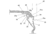
カール部18は、その缶軸方向下方位置に形成されている縮径部17に連続して形成されており、図2及び図3に示すように、缶軸方向に沿う縦断面において、縮径部17の上端で屈曲し缶軸方向に沿って延びる直立部21と、直立部21の上端で半径方向内方に向けて屈曲する内側屈曲部22と、内側屈曲部22に連続し外方に向けて凸となる湾曲面により折り返されてなる天頂折り返し部23と、天頂折り返し部23の折り返し下端で缶軸方向に向けて屈曲する外側屈曲部24と、外側屈曲部24から缶軸方向に延び、直立部21の外周面に対面するカール端部25とを有している。
The curled
この場合、天頂折り返し部23は、図6(b)に示すように、その折り返し下端(外側屈曲部24とほぼ同じ位置)が天頂折り返し部23の最大外径D1よりも小さい外径D2に形成されている(実質的にはカール端部25の外径D2でもある)。また、缶軸方向と直交する方向の幅(天頂折り返し部23の内周縁から外周縁までの距離)W1が、直立部21の内周面からカール端部25の外周面までの半径方向距離W2よりも大きく形成されている。したがって、天頂折り返し部23の内周部は直立部21の内周面よりも半径方向内方に突出し、天頂折り返し部23の外周部はカール端部25の外周面よりも半径方向外方に突出している。この天頂折り返し部23は、その外面の曲率半径Rが0.8mm以上2.5mm以下に形成される。この天頂折り返し部23の上面の曲率半径Rは、単一の曲率半径でもよいし、異なる複数の曲率半径の円弧を連続させてもよい。また、天頂折り返し部23の内周面及び外周面には若干の筒状面23a、23bが形成されるが、この筒状面23a,23bがなく、全体として前述した曲率半径Rでの湾曲面に形成される場合もある。
In this case, as shown in FIG. 6 (b), the
このような形状のボトル缶10において、その他の寸法については必ずしも限定されるものではないが、例えば、元板厚が0.300mm以上0.380mm以下のアルミニウム合金板により、胴部11の厚さ(ウォール厚)が0.110mm以上0.125mm以下、ねじ部16からカール部18までの厚さが0.210mm以上0.230mm以下、カール部18の外径(天頂折り返し部23の最大外径)D1が32.0mm以上35.0mm以下で、幅W1が1.5mm以上3.0mm以下、天頂折り返し部23の缶軸方向の高さHが2.0mm以上4.0mm以下に形成される。
In the bottle can 10 having such a shape, other dimensions are not necessarily limited. For example, the thickness of the
一方、キャップ30は、アルミニウム又はアルミニウム合金の薄板金属からなり、ボトル缶10の口部14に装着される前の形状のキャップ材3では、図1及び図2(a)に示すように、円板状の天面部31と、天面部31の外周縁から垂直下方に延びるスカート部33と、天面部31の内面に設けられたライナ40とを有している。また、スカート部33には、その上部の天面部31に近い位置に、開栓時に手に摩擦力を付与するナール凹部34と、開封時に内圧を開放するためのベントホール35とが周方向に複数ずつ形成され、ベントホール35の上側片35aが半径方向内方に押し込まれた状態に形成されることで、この上側片35aと天面部31との間にライナ40が配置され、抜け止めされる。
スカート部33の下端部には、周方向に断続的にスリット36が形成されており、このスリット36を介してスカート部33が筒上部33aと筒下部33bとに分けられるとともに、スリット36の間に形成される複数のブリッジ37によって、筒上部33aと筒下部33bとが連結した形状とされる。
On the other hand, the
A
ライナ40は、全体が合成樹脂で円盤状に形成され、キャップ材3に対して回転自由に設置される。具体的には、ライナ40は、エラストマー樹脂等で形成されてシール機能を有する密封層41と、その密封層41よりも高い硬度を有し、ポリプロピレン等で形成されてキャップ材3の天面部31と摺動可能な摺動層42との積層構造とされる。密封層41は、摺動層42よりも外径が小さく、外周部には厚肉のシール部43が環状に形成される。シール部43はボトル缶10のカール部18に密着する部分である。
The
ボトル缶10を製造するには、まず、アルミニウム板材を打ち抜いて絞り加工することにより、図4(a)に示すように比較的大径で浅いカップ1を成形した後、このカップ1に再度の絞り加工及びしごき加工(DI加工)を加えて、図4(b)に示すように所定高さの筒体2を成形し、その上端をトリミングにより切り揃える。このDI加工により、筒体2の底部は最終のボトル缶10としての底部10aの形状に成形される。
In order to manufacture the bottle can 10, first, a relatively large diameter and
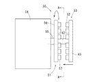
次いで、図7及び図8に示すボトル缶製造装置50により、ボトル缶10を製造する。このボトル缶製造装置50について次に説明する。なお、このボトル缶製造装置50は、前述のようにして形成した筒体2を最終形状のボトル缶10に加工するためのものであり、加工の進捗に応じて缶の形状が変化していくが、以下では、筒体2からボトル缶10に至るまでの間で缶の形状を特に限定しない場合は、中間成形体4として説明する。
Subsequently, the bottle can 10 is manufactured with the bottle can manufacturing
このボトル缶製造装置50は、複数の中間成形体4を、その缶軸方向を水平に配置して保持するワーク保持部51と、これら中間成形体4に各種成形加工を施す複数の成形ツール52を保持するツール保持部53と、両保持部51,53を駆動する駆動部54とを備えている。中間成形体4を保持するワーク保持部51のワーク保持側と、成形ツール52を保持するツール保持部53のツール保持側とが対向して配置されている。
The bottle can manufacturing
ワーク保持部51は、支持軸55に支持された円盤56におけるツール保持部53と対向する表面に、中間成形体4を保持する複数の保持装置57が周方向に沿う環状に配列された構成とされている。この円盤56が駆動部54によって支持軸55を中心として間欠的に回転されることにより、供給部58から供給側スターホイール59を介して供給された中間成形体4の底部が保持装置57に1個ずつ保持されて円盤56の周方向に搬送される。中間成形体4は、円盤56による搬送中にツール保持部53の各成形ツール52によって成形された後、成形後のボトル缶10として排出側スターホイール60を介して排出部61に順次排出される。
The
ツール保持部53は、支持軸62に支持された円盤63におけるワーク保持部51と対向する表面に、複数の各種成形ツール52が周方向に沿う環状に配列され、駆動部54によって円盤63が支持軸62の軸方向に進退する構成とされている。支持軸62は支持軸55の内部に同軸上に設けられる。
In the
このツール保持部53には、中間成形体4の開口部を縮径(ネックイン加工)するための複数のネッキング型、及びねじ部を形成するためのねじ成形ツール、カール部18を形成するためのカール部成形ツール等の、各加工段階に応じた加工を行うための成形ツール52が複数備えられている。これらの成形ツール52は、工程順に円盤63上に周方向に並んで環状に配置されている。
In the
支持軸55の軸線を回転中心とするワーク保持部51(円盤56)の間欠的な回転停止位置は、開口部をツール保持部53側に向けた各中間成形体4の缶軸が各成形ツール52の中心軸にそれぞれ一致するように設定される。そして、駆動部54による円盤56の間欠的回転によって、各中間成形体4は次工程用の各成形ツール52に対向する位置に回転移動されて、次の段階の加工が施される。
The intermittent rotation stop position of the work holding part 51 (disk 56) with the axis of the
すなわち、ツール保持部53が前進してワーク保持部51とツール保持部53とが互いに接近したときに、各成形ツール52が各工程に応じた加工を中間成形体4に施し、両保持部51,53が互いに離間した状態のときに各中間成形体4に次工程の成形ツール52が対向するようにワーク保持部51が回転移動される。このように、両保持部51,53が接近して加工を行い、離間及び回転するという動作が繰り返されることにより、中間成形体4に肩部12、テーパ筒部13、口部14が順次形成されてボトル缶10が形成される。
That is, when the
この場合、まず、図4(c)に示すように、上端部にストレートの円筒部5を有する中間成形体4が形成される。
そして、図5(a)に示すように、テーパ筒部13の上端より若干上方位置から円筒部5を再度拡径した後に、その拡径部分の下端部を除き、上方部分を再度縮径するなどにより、ねじ加工する前の筒状部6を形成する。次いで、この筒状部6にねじ加工を施して、図5(b)に示すようにねじ部16を形成する。このねじ部16が形成された状態では、ねじ部16の上に、上方に向かうにしたがって漸次縮径する縮径部17、及び、その上に連なり缶軸方向に沿うストレートの開口筒部8が形成されている。
そして、その開口筒部8を半径方向外方に折り返して、その先端を缶底方向に向けた折り返し部19を形成する(図5(c))。
In this case, first, as shown in FIG.4 (c), the intermediate molded
Then, as shown in FIG. 5A, after the diameter of the
Then, the
この折り返し部19の加工は、開口筒部8をUターンさせるように折り返す折り返し工程と、これにより形成される折り返し部から天頂折り返し部23を形成する天頂折り返し部形成工程との二工程によって行われる。
まず、折り返し工程では、成形ツール52として図5(b)に二点鎖線で示す拡開用金型52Aと折り返し用金型52Bとが用いられる。これら拡開用金型52A及び折り返し用金型52Bは、それぞれロール状に形成され、矢印で示すように回転自在であるとともに、開口筒部8の周方向に沿って旋回自在に支持されており、旋回しながら開口筒部8を缶底方向に向けて押圧することにより、拡開用金型52Aによって開口筒部8を外方に開いた後、折り返し用金型52Bによって折り返す。
The processing of the folded
First, in the folding process, as the forming
図6(a)は、このようにして成形された折り返し部19を示しており、缶軸方向の先端部が上方に凸となる円弧面に形成され、その下方に開口筒部8の残りの部分と折り返し部19の端部19aがほぼ平行に配置される。この缶軸方向の先端部において上方に凸となっている円弧面は天頂折り返し部23の上面を形成する。
次に、天頂折り返し部形成工程では、成形ツール52として、図6(a)に二点鎖線で示すように、折り返し部19により形成される開口部内に挿入される内側ロール52Cと、折り返し部19の半径方向外方に配置した外側ロール52Dとを用いて折り返し部19を加工する。具体的には、両ロール52C,52Bを相互に接近させることにより、折り返し部19の下方に残った開口筒部8の下端部及び折り返し部19の下端部19aを両側から板厚方向に押しつぶすように押圧して挟持することにより、図6(b)に示すように、その挟持部分よりも上方に天頂折り返し部23を形成する。内側ロールで押圧された部分には、内側屈曲部22と直立部21が形成され、外側ロールで押圧された部分には、外側屈曲部24とカール端部25が形成される。これにより、カール部18の成形が完了する。なお、カール端部25の下端は、前述した拡開用金型52Aによって開口筒部8の先端が拡げられたときの成形痕により、わずかに屈曲した状態に形成される。
FIG. 6A shows the folded
Next, in the zenith folded portion forming step, as the forming
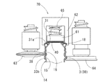
このようにして製造したボトル缶10の口部14にキャップ材3を被着してキャッピング加工を施すためには、例えば、図9に示すようなキャッピングヘッド70を複数備えるキャッピング装置が用いられる。そして、このキャッピングヘッド70によって、ボトル缶10に対するキャップ材3の被着が行われる。
このキャッピングヘッド70は、キャップ押さえ61を備えたプレッシャーブロック62と、ROロール(ロールオンロール)としての第1ロール63と、PPロール(ピルファープルーフロール)としての第2ロール64とを備えている。プレッシャーブロック62は下端部が筒状に形成されており、その内側に配置されるキャップ押さえ61との間で缶軸方向に相対移動可能であり、キャップ押さえ61との間にばね65が設けられている。また、第1ロール63及び第2ロール64はプレッシャーブロック62の周囲を旋回可能かつ缶軸方向に移動可能に支持されている。
In order to attach the
The capping
そして、ボトル缶10の口部14にキャップ材3を被せた状態でキャップ押さえ61がキャップ材3のキャップ材3の天面部31を押さえ、その状態でプレッシャーブロック62が天面部31の外周部に絞り成形を施すことにより段部31aを形成する。また、第1ロール63によりキャップ材3にキャップねじ部38を成形するとともに、第2ロール64により筒下部33bを膨出部15に巻き込んで固定する構成とされる。
このようにキャッピングされることで、キャップ30内のライナ40が、ボトル缶10の口部14に押し付けられ、内部を密封する。
Then, the
By being capped in this manner, the
以上のように構成したボトル缶10においては、カール部18における天頂折り返し部23の外面全面が外方に向けて凸となる湾曲面に形成されていることで、キャッピンズ時の缶軸方向の荷重により、天頂折り返し部23の湾曲した上面にライナ40が密着するとともに、プレッシャーブロック62によりキャップ30の天面部31の周縁部が絞り加工されることにより、天頂折り返し部23の外周面にもライナ40が密着する。この天頂折り返し部23は、外面が湾曲面により形成されているので、その湾曲面がライナ40に食い込むが、その曲率半径Rが0.8mm以上2.5mm以下に形成されているので、食い込みによるライナ40の局部的な薄肉部の発生が抑制され、ライナ40の健全性を長期に維持することができる。
In the bottle can 10 configured as described above, the entire outer surface of the
そして、このように、天頂折り返し部23の上面から外周面にかけた広い範囲でライナ40に密着しているので、陽圧状態(炭酸ガス入り飲料、窒素ガス封入飲料等)の内容物の圧力が上昇して、キャップ30の天面部31がライナ40とともに缶軸方向上方へ膨出する方向に変形したとしても、天頂折り返し部23の外周面でライナ40が引っ掛かり、内圧上昇によるライナ40の持ち上がりが規制され、天頂折り返し部23の外周面の密着状態が維持される。このため、密封性を良好に維持することができる。
In this way, the pressure in the contents of the positive pressure state (a beverage containing carbon dioxide gas, a beverage filled with nitrogen gas, etc.) is high because it is in close contact with the
以上のように構成されるボトル缶は、前述したほぼシート状のライナを備えるキャップの他にも、図10及び図11に示すように成形されたライナ44を備えるキャップ30にも適用することができる。以下の説明及び図10及び図11では、前述の実施形態と共通部分について同一符号を付してその説明を省略する。
図10は、(a)はキャップ材3をボトル缶10に被せた状態の縦断面図、(b)はボトル缶10にキャップ30が巻締められた後の状態の縦断面図である。
このライナ44は、密封層45の外周部に、内側凸条46と外側凸条47とが同心円の二重の環状に形成され、これら両凸条46,47の間に凹溝部48が形成されており、これら内側凸条46、外側凸条47、凹溝部48からなるシール部49が環状に形成されている。
The bottle can configured as described above can be applied to the
10A is a longitudinal sectional view of the bottle can 10 covered with the
In this
このキャップ材3をボトル缶10のカール部18に被せると、図10(a)に示すように、シール部49の凹溝部48内にカール部18が挿入される。そして、図10(b)及び図11に示すように、凹溝部48の底面が天頂折り返し部23の上面に密接するとともに、プレッシャーブロック62により、キャップ材3の天面部31の外周側が缶底方向に押圧されながら絞り加工されることで、天面部31の周縁部に段部31aが形成され、ライナ44の外側凸条47が、天頂折り返し部23の外周面に押しつけられる。また、この外側凸条47が変形することにより、内側凸条46がカール部18に引き寄せられて、内側凸条46の外周面が天頂折り返し部23の内周面に密着する。
When the
この場合、両凸条46,47の缶軸方向の長さLは、天頂折り返し部23の高さH(図6(b)参照)より大きく、かつ、両凸条46,47の内面間の距離、つまり凹溝部48の缶軸方向と直交する方向の幅W3は、天頂折り返し部23の幅W1(図6(b)参照)と同じか、それより小さく設定しておく。
このように設定しておくことにより、天頂折り返し部23を凹溝部48内に嵌合すると、その嵌合の初期段階では両凸条46,47の間隔が押し広げられるが、天頂折り返し部23の上面が凹溝部48の底面に食い込むと、天頂折り返し部23の下方に達した両凸条46,47の下端部が、キャッピングの押圧力及びシール部49の弾性力により、相互に接近する方向に間隔が狭められる。また、キャップ3の天面部31の周縁部31aではプレッシャーブロック62による絞り作用も生じる。したがって、図10(b)及び図11に示すように、天頂折り返し部23の下向きの湾曲面から内側屈曲部22の内周面及び外側屈曲部24の外周面、さらには、これらの下方の直立部21の内周面及びカール端部47の外周面にも凸条46,47が密接する。これにより、このボトル缶10では、両凸条46,47と凹溝部48とを有するライナ44を備えたキャップ30に適用することにより、これら両凸条46,47及び凹溝部48により形成される内側表面の広い面積に密着し、高い密封性を得ることができる。
In this case, the length L of the two
By setting in this way, when the
3 キャップ材
4 中間成形体
5 円筒部
6 筒状部
8 小筒部
10 ボトル缶
14 口部
15 膨出部
16 ねじ部
17 縮径部
18 カール部
21 直立部
22 内側屈曲部
23 天頂折り返し部
23a、23b 筒状面
24 外側屈曲部
25 カール端部
30 キャップ
31 天面部
31a 段部
33 スカート部
33a 筒上部
33b 筒下部
34 ナール凹部
35 ベントホール
35a 上側片
36 スリット
37 ブリッジ
38 キャップねじ部
40,44 ライナ
41,45 密封層
42 摺動層
43,49 シール部
46 内側凸条
47 外側凸条
48 凹溝部
52A 拡開用金型
52B 折り返し用金型
52C 内側ロール
52D 外側ロール
62 プレッシャーブロック
63 第1ロール
64 第2ロール
65 ばね
70 キャッピングヘッド
3
Claims (1)
前記カール部の外周面は、缶軸方向に沿う縦断面において、前記カール部の上端から連続して径方向外方に向けて凸となる湾曲面により折り返されてなる天頂折り返し部と、前記天頂折り返し部の折り返し下端に連続する外側屈曲部と、外側屈曲部から連続するカール端部とを有し、
前記カール端部は、前記天頂折り返し部の最大外径よりも小さい外径に形成されているボトル缶を製造する方法であって、
前記ボトル缶となる中間成形体の開口端部に缶軸方向に沿って開口筒部を形成しておき、前記開口筒部の端部を半径方向外方に開いて折り返してなる折り返し部を形成した後、前記折り返し部の缶軸方向の先端側より下方部分をロールで半径方向外方から押圧することにより、前記缶軸方向の先端側に前記天頂折り返し部を形成するとともに、前記ロールで押圧された部分に前記外側屈曲部と前記カール端部とを形成することを特徴とするボトル缶の製造方法。 The outer periphery of the mouth portion, have a open end and a curled portion that is formed is folded radially outwardly, and a threaded portion formed on the can axis direction lower position of the curl portion,
The outer circumferential surface of the curled portion has a zenith folding portion that is folded back by a curved surface that protrudes radially outward continuously from the upper end of the curled portion in a longitudinal section along the can axis direction, and the zenith An outer bent portion that continues to the lower end of the folded portion of the folded portion, and a curled end portion that continues from the outer bent portion,
The curled end is a method of manufacturing a bottle can formed to have an outer diameter smaller than the maximum outer diameter of the zenith folded portion ,
An opening tube portion is formed along the can axis direction at the opening end portion of the intermediate molded body to be the bottle can, and a folded portion is formed by opening the end portion of the opening tube portion radially outward and turning it back. After that, by pressing the lower part from the distal end side in the can axis direction of the folded portion from the outside in the radial direction with a roll, the zenith folded portion is formed on the distal end side in the can axis direction and pressed with the roll. method for producing a bottle can, which comprises forming a portion in said curled end portion and the outer bend.
Priority Applications (1)
| Application Number | Priority Date | Filing Date | Title |
|---|---|---|---|
| JP2017023574A JP6476219B2 (en) | 2017-02-10 | 2017-02-10 | Manufacturing method for bottle cans |
Applications Claiming Priority (1)
| Application Number | Priority Date | Filing Date | Title |
|---|---|---|---|
| JP2017023574A JP6476219B2 (en) | 2017-02-10 | 2017-02-10 | Manufacturing method for bottle cans |
Related Child Applications (1)
| Application Number | Title | Priority Date | Filing Date |
|---|---|---|---|
| JP2019017590A Division JP7126459B2 (en) | 2019-02-04 | 2019-02-04 | bottle can |
Publications (3)
| Publication Number | Publication Date |
|---|---|
| JP2018127272A JP2018127272A (en) | 2018-08-16 |
| JP2018127272A5 JP2018127272A5 (en) | 2018-09-27 |
| JP6476219B2 true JP6476219B2 (en) | 2019-02-27 |
Family
ID=63173480
Family Applications (1)
| Application Number | Title | Priority Date | Filing Date |
|---|---|---|---|
| JP2017023574A Active JP6476219B2 (en) | 2017-02-10 | 2017-02-10 | Manufacturing method for bottle cans |
Country Status (1)
| Country | Link |
|---|---|
| JP (1) | JP6476219B2 (en) |
Families Citing this family (1)
| Publication number | Priority date | Publication date | Assignee | Title |
|---|---|---|---|---|
| JP6515952B2 (en) * | 2017-05-19 | 2019-05-22 | 東洋製罐株式会社 | Method of manufacturing bottle can, bottle can with cap, and bottle can |
Family Cites Families (8)
| Publication number | Priority date | Publication date | Assignee | Title |
|---|---|---|---|---|
| JP3521402B2 (en) * | 1999-11-26 | 2004-04-19 | 武内プレス工業株式会社 | Metal can with screw that can maintain high sealing performance |
| JP3788371B2 (en) * | 2002-02-27 | 2006-06-21 | 三菱マテリアル株式会社 | Bottle can with bottle and bottle can |
| JP2004175386A (en) * | 2002-11-26 | 2004-06-24 | Mitsubishi Materials Corp | Bottle can, cap, bottle can with cap, and bottle can manufacturing method |
| JP4298402B2 (en) * | 2003-06-30 | 2009-07-22 | ユニバーサル製缶株式会社 | Bottle can, bottle with cap and method for producing bottle can |
| KR100982152B1 (en) * | 2003-08-28 | 2010-09-14 | 유니버설세이칸 가부시키가이샤 | Bottle manufacturing equipment |
| JP4707172B2 (en) * | 2005-01-07 | 2011-06-22 | 大和製罐株式会社 | Can container with pilfer proof cap |
| JP5038934B2 (en) * | 2008-02-22 | 2012-10-03 | 日本クラウンコルク株式会社 | Combination of container and container lid |
| EP3241773A1 (en) * | 2009-04-06 | 2017-11-08 | Takeuchi Press Industries Co., Ltd. | Metal bottle can |
-
2017
- 2017-02-10 JP JP2017023574A patent/JP6476219B2/en active Active
Also Published As
| Publication number | Publication date |
|---|---|
| JP2018127272A (en) | 2018-08-16 |
Similar Documents
| Publication | Publication Date | Title |
|---|---|---|
| US9358604B2 (en) | System for compression relief shaping | |
| TW495398B (en) | Bottle-shaped can manufacturing method, and forming tool | |
| JPWO2012133391A1 (en) | Threaded bottle can manufacturing method and threaded bottle can | |
| US11878832B2 (en) | Bottle-shaped can with cap and manufacturing apparatus thereof | |
| JP5090290B2 (en) | Bottle can | |
| TW201738013A (en) | Can and method for forming curled section in can mouth | |
| JP6476219B2 (en) | Manufacturing method for bottle cans | |
| JP6546946B2 (en) | Bottle with cap | |
| JP2018127229A (en) | Bottle can | |
| JP6137915B2 (en) | Manufacturing method of cap with liner | |
| JP2019136740A (en) | Molding device and molding method of neck part of bottle type can | |
| JP6965076B2 (en) | How to make bottle cans | |
| JP2018114989A (en) | Bottle can | |
| JP7170018B2 (en) | bottle can | |
| JP7126459B2 (en) | bottle can | |
| JP2018131246A (en) | Bottle can | |
| JP2017109760A (en) | Capping method | |
| JP4342988B2 (en) | Bottle can body manufacturing apparatus and bottle can body manufacturing method | |
| JP4606266B2 (en) | Capping device | |
| JP6748406B2 (en) | Capping method | |
| JP7207873B2 (en) | Bottle can manufacturing method | |
| JP2016137915A (en) | Capping method and capping device | |
| JP6496868B1 (en) | Manufacturing method for bottle cans | |
| EP1007426A1 (en) | Resealable beverage container and top therefor | |
| JP7260980B2 (en) | Bottle can manufacturing method |
Legal Events
| Date | Code | Title | Description |
|---|---|---|---|
| A521 | Request for written amendment filed |
Free format text: JAPANESE INTERMEDIATE CODE: A523 Effective date: 20180629 |
|
| A621 | Written request for application examination |
Free format text: JAPANESE INTERMEDIATE CODE: A621 Effective date: 20180629 |
|
| A871 | Explanation of circumstances concerning accelerated examination |
Free format text: JAPANESE INTERMEDIATE CODE: A871 Effective date: 20180629 |
|
| A975 | Report on accelerated examination |
Free format text: JAPANESE INTERMEDIATE CODE: A971005 Effective date: 20180713 |
|
| A131 | Notification of reasons for refusal |
Free format text: JAPANESE INTERMEDIATE CODE: A131 Effective date: 20180925 |
|
| A521 | Request for written amendment filed |
Free format text: JAPANESE INTERMEDIATE CODE: A523 Effective date: 20181122 |
|
| TRDD | Decision of grant or rejection written | ||
| A01 | Written decision to grant a patent or to grant a registration (utility model) |
Free format text: JAPANESE INTERMEDIATE CODE: A01 Effective date: 20190108 |
|
| A61 | First payment of annual fees (during grant procedure) |
Free format text: JAPANESE INTERMEDIATE CODE: A61 Effective date: 20190204 |
|
| R150 | Certificate of patent or registration of utility model |
Ref document number: 6476219 Country of ref document: JP Free format text: JAPANESE INTERMEDIATE CODE: R150 |
|
| R250 | Receipt of annual fees |
Free format text: JAPANESE INTERMEDIATE CODE: R250 |
|
| S533 | Written request for registration of change of name |
Free format text: JAPANESE INTERMEDIATE CODE: R313533 |
|
| R350 | Written notification of registration of transfer |
Free format text: JAPANESE INTERMEDIATE CODE: R350 |
|
| R250 | Receipt of annual fees |
Free format text: JAPANESE INTERMEDIATE CODE: R250 |
|
| R250 | Receipt of annual fees |
Free format text: JAPANESE INTERMEDIATE CODE: R250 |