JP6466157B2 - Heavy oil-fired boiler combustion method and heavy oil-fired boiler - Google Patents
Heavy oil-fired boiler combustion method and heavy oil-fired boiler Download PDFInfo
- Publication number
- JP6466157B2 JP6466157B2 JP2014254198A JP2014254198A JP6466157B2 JP 6466157 B2 JP6466157 B2 JP 6466157B2 JP 2014254198 A JP2014254198 A JP 2014254198A JP 2014254198 A JP2014254198 A JP 2014254198A JP 6466157 B2 JP6466157 B2 JP 6466157B2
- Authority
- JP
- Japan
- Prior art keywords
- heavy oil
- combustion
- fuel
- spray particles
- burner
- Prior art date
- Legal status (The legal status is an assumption and is not a legal conclusion. Google has not performed a legal analysis and makes no representation as to the accuracy of the status listed.)
- Active
Links
Images


Description
本発明は、アスファルト等の重質油を燃料とする重質油焚きボイラに係り、特に、複数種の燃料油を同時に燃焼させるボイラから排出される煤塵量を低減する重質油焚きボイラの燃焼方法及び重質油焚きボイラに関する。 The present invention relates to a heavy oil fired boiler that uses heavy oil such as asphalt as fuel, and more particularly, combustion of a heavy oil fired boiler that reduces the amount of dust discharged from a boiler that simultaneously burns multiple types of fuel oil The present invention relates to a method and a heavy oil fired boiler.
従来の油焚きボイラは、液体燃料を蒸気等の噴霧媒体により微粒化(霧化)させた状態で火炉内に吹き込み、火炎を形成して燃焼させている。このような油焚きバーナで使用される燃焼バーナは、液体燃料及び噴霧媒体の供給配管先端部に設けたバーナチップを備えている。このバーナチップは、液体燃料及び噴霧媒体を混合して微粒化した後、先端に形成された複数の噴出孔から微粒化燃料を噴射可能となっている。 In a conventional oil-fired boiler, liquid fuel is blown into a furnace in a state of being atomized (atomized) with a spray medium such as steam to form a flame and burned. A combustion burner used in such an oil-burning burner includes a burner tip provided at the tip of a supply pipe for liquid fuel and spray medium. This burner tip is capable of injecting atomized fuel from a plurality of ejection holes formed at the tip after mixing and atomizing the liquid fuel and the spray medium.
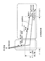
図5に示す従来の重質油焚きボイラ10Aは、アスファルト等の重質油を燃焼させるものであり、火炉11と燃焼装置12Aとを有している。
燃焼装置12Aは、火炉壁の上下方向に複数段(図示の例では5段)が装着された燃焼バーナ20Aを有している。なお、各段には、例えば周方向に沿って4個が均等間隔で配設されており、各段の燃焼バーナ20Aは全て同じ仕様である。
A conventional heavy oil-fired
The
各燃焼バーナ20Aは、燃料の重質油及び噴霧用蒸気を導入し、重質油と噴霧用蒸気とを混合する。この結果、重質油を微粒化して重質油噴霧粒子を含む混合流体が燃焼バーナ20Aから火炉11内に噴射され、これを燃焼させて火炎を形成する。こうして火炉11内の下部に火炎が生じると、燃焼ガス(排ガス)が火炉11内を上昇し、煙道31を通って排ガス管37に導かれる。
なお、図中の符号13は燃料供給配管、14は蒸気供給配管、32は二次過熱器、33は一次過熱器、34,35は蒸発器、36は節炭器で、40は二次空気(OFA;Over Fire Air)、50は追加空気投入部より供給される二段燃焼空気(AA;Additional Air)である。
Each
In the figure, reference numeral 13 is a fuel supply pipe, 14 is a steam supply pipe, 32 is a secondary superheater, 33 is a primary superheater, 34 and 35 are evaporators, 36 is a economizer, and 40 is secondary air. (OFA; Over Fire Air), 50 is a two-stage combustion air (AA) supplied from the additional air input unit.
従来の油焚きボイラでは、例えば下記の特許文献1に開示されているように、窒素酸化物(NOx)及び煤煙を抑制するため、内部混合形高圧気流噴霧式燃焼方法及び油バーナのバーナチップを改善することが行われている。
また、下記の特許文献2に開示されているように、微粉固体を含有するスラリ状燃料の高効率、低公害燃焼を図るため、内部混合式アトマイザの空気投入方法を改善する技術も知られている。
さらに、下記の特許文献3には、同一燃料油を対象として、油焚きボイラ全体における燃料の投入方法改善に関する技術が開示されている。
In conventional oil-fired boilers, for example, as disclosed in Patent Document 1 below, in order to suppress nitrogen oxides (NOx) and soot, an internal mixed high-pressure air spray combustion method and a burner tip of an oil burner are provided. Improvements are being made.
In addition, as disclosed in Patent Document 2 below, a technique for improving the air injection method of an internal mixing atomizer is also known in order to achieve high efficiency and low pollution combustion of a slurry-like fuel containing finely divided solids. Yes.
Furthermore, the following Patent Document 3 discloses a technique related to improving the fuel injection method in the entire oil-fired boiler for the same fuel oil.
ところで、アスファルト等の重質油を燃料とする重質油焚きボイラでは、重質油の燃料特性から、燃焼後にボイラから排出される煤塵量(未燃分)が多いという問題を有している。このような煤塵対策として、従来は微粒化に用いる蒸気(噴霧媒体)の消費率をアップさせた低煤塵アトマイザを使用している。しかし、この蒸気は、ボイラで発生させた蒸気の一部を利用するものであるから、消費蒸気量が多いことはボイラ効率の悪化に繋がるため好ましくない。 By the way, heavy oil fired boilers that use heavy oil such as asphalt have a problem that the amount of dust discharged from the boiler after combustion is large due to the fuel characteristics of heavy oil. . As a measure against such dust, conventionally, a low dust atomizer with an increased consumption rate of steam (atomizing medium) used for atomization is used. However, since this steam uses a part of the steam generated in the boiler, it is not preferable to consume a large amount of steam because it leads to deterioration of boiler efficiency.
また、従来の重質油焚きバーナ10Aは、同仕様の燃焼バーナ20Aが上下方向に複数段配置されている。このため、図5に示すように、下段側の燃焼バーナ20Aから投入された重質油噴霧粒子の粒子軌跡(実線表示)と、上段側の燃焼バーナ20Aから投入された重質油噴霧粒子の粒子軌跡(破線表示)とを比較すると、下段側の燃焼バーナ20Aから投入された重質油噴霧粒子の粒子軌跡が長くなり、この結果、重質油噴霧粒子が火炉11内にある滞留時間も長くなる。
なお、ボイラによっては、複数種の燃料油を同時に燃焼させることもあるが、燃料油の投入方法に関する明確な指針は見当たらない。
Further, in the conventional heavy
Some boilers may burn multiple types of fuel oil at the same time, but there is no clear guideline on how to add fuel oil.
このような背景から、異なる複数種の燃料油を同時に燃焼させる重質油焚きボイラにおいては、排出される煤塵量を増加させることがなく、しかも、重質油の微粒化に消費される噴霧媒体の消費率を抑制できる燃焼方法及び重質油焚きボイラが望まれる。
本発明は、上記の課題を解決するためになされたもので、その目的とするところは、複数種の燃料油を同時に燃焼させるボイラに適用され、煤塵排出量を増加させることなく噴霧媒体の消費率抑制を可能にする重質油焚きボイラの燃焼方法及び重質油焚きボイラを提供することにある。
From such a background, in heavy oil fired boilers that simultaneously burn different types of fuel oil, the spray medium that does not increase the amount of dust discharged and is consumed for atomization of heavy oil A combustion method and heavy oil fired boiler that can suppress the consumption rate of the oil are desired.
The present invention has been made in order to solve the above-described problems, and the object of the present invention is to be applied to a boiler that simultaneously burns a plurality of types of fuel oil and consumes the spray medium without increasing the amount of dust emission. An object of the present invention is to provide a heavy oil-fired boiler combustion method and a heavy oil-fired boiler that can suppress the rate.
本発明は、上記の課題を解決するため、下記の手段を採用した。
本発明に係る重質油焚きボイラの燃焼方法は、燃焼バーナの燃料噴霧器に重質油燃料及び微粒化流体を導入して混合し、微粒化された重質油噴霧粒子を含む混合流体を燃焼用空気とともに火炉内へ噴射投入して燃焼させる重質油焚きボイラの燃焼方法であって、前記重質油燃料として残留炭素分が10%以上となる燃料油を含む複数の油種を同時に燃焼させ、前記火炉の上下方向に複数段配置されている前記燃焼バーナから各々噴射投入される前記重質油噴霧粒子について、上段側に配置した1または複数段の前記燃焼バーナから噴射投入される前記重質油噴霧粒子の燃焼性が、下段側に配置した1または複数段の前記燃焼バーナから噴射投入される前記重質油噴霧粒子の燃焼性より高く設定されることを特徴とするものである。
In order to solve the above problems, the present invention employs the following means.
The combustion method of a heavy oil fired boiler according to the present invention is to introduce a heavy oil fuel and atomized fluid into a fuel atomizer of a combustion burner, mix them, and burn a mixed fluid containing atomized heavy oil spray particles A method of burning a heavy oil-fired boiler that is injected into a furnace together with industrial air and combusts, and simultaneously burns a plurality of oil types including fuel oil having a residual carbon content of 10% or more as the heavy oil fuel The heavy oil spray particles injected and injected from the combustion burners arranged in a plurality of stages in the vertical direction of the furnace are injected and injected from one or more stages of the combustion burners arranged on the upper stage side. The flammability of the heavy oil spray particles is set to be higher than the flammability of the heavy oil spray particles injected from one or more stages of the combustion burner arranged on the lower stage side. .
このような重質油焚きボイラの燃焼方法によれば、火炉の上下方向に複数段配置されている燃焼バーナから各々噴射投入される重質油噴霧粒子は、上段側に配置した1または複数段の燃焼バーナから噴射投入される重質油噴霧粒子の燃焼性が、下段側に配置した1または複数段の燃焼バーナから噴射投入される重質油噴霧粒子の燃焼性より高く設定されている。このため、下段側の燃焼バーナから噴射投入された燃焼性の低い(悪い)重質油噴霧粒子は、上段側の燃焼バーナから噴射投入された燃焼性の高い(良い)重質油噴霧粒子と比較して、火炉内における重質油噴霧粒子の粒子軌跡が長くなるとともに、火炉内の滞留時間も長くなる。 According to the combustion method of such a heavy oil fired boiler, the heavy oil spray particles injected and injected from the combustion burners arranged in a plurality of stages in the vertical direction of the furnace are one or more stages arranged on the upper stage side. The combustion property of the heavy oil spray particles injected from the combustion burner is set higher than the combustion property of the heavy oil spray particles injected from the one or more stages of combustion burners arranged on the lower side. For this reason, low (bad) heavy oil spray particles injected from the lower combustion burner are injected with high (good) heavy oil spray particles injected from the upper combustion burner. In comparison, the particle trajectory of heavy oil spray particles in the furnace becomes longer, and the residence time in the furnace becomes longer.
すなわち、火炉内の滞留時間が短い(重質油噴霧粒子の燃焼時間が短い)上段側の燃焼バーナには燃焼性の高い重質油噴霧粒子が噴霧投入され、かつ、火炉内の滞留時間が長い(重質油噴霧粒子の燃焼時間が長い)下段側の燃焼バーナには燃焼性の低い重質油噴霧粒子が噴霧投入される。このため、ボイラ出口に到達するまでの間に燃焼しないで未燃分となりやすい燃焼性の低い重質油噴霧粒子に対して、長い火炉内滞留時間及び燃焼時間が確保されているので、ボイラ出口における煤塵量の増加を抑制することができ、また、微粒化流体の消費率についても同様に抑制することができる。 That is, the residence time in the furnace is short (the combustion time of heavy oil spray particles is short), and the combustion oil on the upper stage is sprayed with highly combustible heavy oil spray particles, and the residence time in the furnace is Heavy oil spray particles having low combustibility are sprayed into a long lower combustion burner (the combustion time of heavy oil spray particles is long). For this reason, since a long residence time and combustion time in the furnace are secured for heavy oil spray particles with low flammability that do not burn before reaching the boiler outlet and are likely to become unburned, the boiler outlet An increase in the amount of dust can be suppressed, and the consumption rate of the atomized fluid can be similarly suppressed.
上記の発明において、前記燃焼性の高低は、

本発明に係る重質油焚きボイラは、燃焼バーナの燃料噴霧器に重質油燃料及び微粒化流体を導入して混合し、微粒化された重質油噴霧粒子を含む混合流体を燃焼用空気とともに火炉内へ噴射投入して燃焼させる重質油焚きボイラであって、前記重質油燃料として残留炭素分が10%以上となる燃料油を含む複数の油種を同時に燃焼させ、火炉の上下方向に複数段配置されて各々前記重質油噴霧粒子を噴射投入する前記燃焼バーナは、上段側に配置された1または複数段の上段バーナと下段側に配置された1または複数段の下段バーナとを備え、前記上段バーナから噴射投入される前記重質油噴霧粒子の燃焼性が、前記下段バーナから噴射投入される前記重質油噴霧粒子の燃焼性より高く設定されていることを特徴とするものである。 A heavy oil fired boiler according to the present invention introduces and mixes heavy oil fuel and atomized fluid into a fuel sprayer of a combustion burner, and mixes the mixed fluid containing atomized heavy oil spray particles together with combustion air. A heavy oil fired boiler that injects and burns into a furnace, and simultaneously burns a plurality of oil types including fuel oil with a residual carbon content of 10% or more as the heavy oil fuel, and the vertical direction of the furnace The combustion burner that is arranged in a plurality of stages and injects and inputs the heavy oil spray particles, respectively, includes one or more upper burners arranged on the upper stage side, and one or more lower burners arranged on the lower stage side. And the combustion property of the heavy oil spray particles injected from the upper burner is set higher than the combustion property of the heavy oil spray particles injected from the lower burner. Is.
このような重質油焚きボイラによれば、火炉の上下方向に複数段配置されて各々重質油噴霧粒子を噴射投入する燃焼バーナは、上段側に配置された1または複数段の上段バーナと下段側に配置された1または複数段の下段バーナとを備えており、上段バーナから噴射投入される重質油噴霧粒子の燃焼性が、下段バーナから噴射投入される重質油噴霧粒子の燃焼性より高く設定されている。このため、下段バーナから噴射投入される燃焼性の低い(悪い)重質油噴霧粒子は、上段バーナから噴射投入された燃焼性の高い(良い)重質油噴霧粒子と比較して、火炉内における重質油噴霧粒子の粒子軌跡が長くなるとともに、火炉内の滞留時間も長くなる。 According to such a heavy oil-fired boiler, the combustion burner that is arranged in a plurality of stages in the vertical direction of the furnace and injects and inputs heavy oil spray particles, respectively, has one or more upper burners arranged on the upper stage side. One or a plurality of lower burners arranged on the lower stage side, and the combustibility of the heavy oil spray particles injected from the upper burner is the combustion of the heavy oil spray particles injected from the lower burner It is set higher than sex. Therefore, heavy oil spray particles with low (bad) flammability injected from the lower burner are compared with heavy oil spray particles with high flammability (good) injected from the upper burner. As a result, the particle trajectory of heavy oil spray particles becomes longer and the residence time in the furnace also becomes longer.
すなわち、火炉内の滞留時間が短い(重質油噴霧粒子の燃焼時間が短い)上段バーナには燃焼性の高い重質油噴霧粒子が噴霧投入され、かつ、火炉内の滞留時間が長い(重質油噴霧粒子の燃焼時間が長い)下段バーナには燃焼性の低い重質油噴霧粒子が噴霧投入されるので、ボイラ出口に到達するまでの間に燃焼しないで未燃分となりやすい燃焼性の低い重質油噴霧粒子に対して、長い火炉内滞留時間及び燃焼時間が確保されている。従って、ボイラ出口における煤塵量の増加を抑制することができ、また、微粒化流体の消費率についても同様に抑制することができる。 That is, the residence time in the furnace is short (the combustion time of heavy oil spray particles is short), and the heavy burner oil spray particles with high combustibility are sprayed into the upper burner and the residence time in the furnace is long (heavy (The combustion time of the fine oil spray particles is long.) The lower burner is charged with heavy oil spray particles with low combustibility. A long furnace residence time and combustion time is ensured for low heavy oil spray particles. Therefore, an increase in the amount of dust at the boiler outlet can be suppressed, and the consumption rate of the atomized fluid can be similarly suppressed.
上記の発明において、前記燃焼性の高低は、
上述した本発明によれば、重質油燃料として残留炭素分が10%以上となる燃料油を含む複数の油種を同時に燃焼させる重質油焚きボイラにおいて、火炉内の粒子軌跡(滞留時間)を有効利用して燃焼性の低い燃料を可能な限り長く燃焼させることにより、蒸気等の微粒化流体消費率を増加させることなく、ボイラ出口から排出される煤塵量を抑制することが可能になる。 According to the present invention described above, in a heavy oil-fired boiler that simultaneously burns a plurality of oil types including fuel oil having a residual carbon content of 10% or more as heavy oil fuel, particle trajectory (residence time) in the furnace. It is possible to suppress the amount of dust discharged from the boiler outlet without increasing the consumption rate of the atomized fluid such as steam by effectively burning the low-combustibility fuel as long as possible. .
以下、本発明に係る重質油焚きボイラの燃焼方法及び重質油焚きボイラの一実施形態を図面に基づいて説明する。
図1に示す実施形態の重質油焚きボイラ10は、例えば流体燃料としてアスファルト等の重質油を複数種用いて同時に燃焼させるコンベンショナルボイラである。この重質油焚きボイラ10は、火炉11と燃焼装置12とを有している。火炉11は、例えば四角筒の中空形状をなして鉛直方向に沿って設置され、この火炉11を構成する火炉壁の下部に燃焼装置12が設けられている。
Hereinafter, an embodiment of a combustion method of a heavy oil-fired boiler and a heavy oil-fired boiler according to the present invention will be described based on the drawings.
A heavy oil fired
本実施形態における重質油は、残留炭素成分が10%以上の重油と定義される。すなわち、本実施形態における重質油は、工業分析の分析項目である残留炭素の値を用いて重油を限定したものであり、具体的にはC重油以上の重質油を意味している。 The heavy oil in this embodiment is defined as heavy oil having a residual carbon component of 10% or more. That is, the heavy oil in this embodiment limits heavy oil using the value of the residual carbon which is an analysis item of industrial analysis, and specifically means heavy oil equal to or higher than C heavy oil.
燃焼装置12は、火炉壁に装着された複数の燃焼バーナ20を有している。本実施形態の燃焼バーナ20は、周方向に沿って、例えば、4個が均等間隔で配設されたものを1セットとして、例えば、5セット、すなわち上下方向に5段配置されている。なお、燃焼バーナ20の配置場所や個数については、図示の構成に限定されるものではない。
各燃焼バーナ20は、燃料の重質油を導入するため、燃料供給配管13を介して燃料供給源(不図示)に連結されており、燃料供給配管13には燃料供給量の調整を行う流量調整弁(不図示)が設けられている。また、各燃焼バーナ20は、微粒化流体の噴霧用蒸気を導入するため、各蒸気供給配管14を介して蒸気供給源(不図示)に連結されており、蒸気供給配管14には蒸気供給量の調整を行う流量調整弁(不図示)が設けられている。
The
Each
従って、各燃焼バーナ20は、燃料供給源から燃料供給配管13を通して燃料の重質油が供給されるとともに、蒸気供給源から蒸気供給配管14を通して噴霧用蒸気が供給されることとなる。このため、各燃焼バーナ20は、重質油と噴霧用蒸気とを混合することにより、重質油を微粒化して重質油噴霧粒子を含む混合流体として火炉11内に噴射し、これを燃焼させて火炎を形成することができる。
Therefore, each
火炉11は、上部に煙道31が連結されている。この煙道31には、対流伝熱部(熱回収部)として排ガスの熱を回収するため、例えばバーナ側から順に二次過熱器32,一次過熱器33,蒸発器34,35及び節炭器(エコノマイザ)36が設けられており、火炉11での燃焼で発生した排ガスと水との間で熱交換が行われる。なお、これらの熱交換器類については、その配置や数等を例示したものであり、特に限定されるものではない。
煙道31は、その下流側に熱交換を行った排ガスを排出する排ガス管37が連結されている。この排ガス管37には、図示しない脱硝装置、電気集塵機、誘引送風機、脱硫装置が設けられ、下流端部に煙突が設けられている。
The
The
従って、燃焼装置12において、各燃焼バーナ20が重質油と噴霧用蒸気との混合流体を火炉11内に噴射すると、火炉11では、混合流体と空気とが燃焼して火炎を生じる。こうして火炉11内の下部で火炎が生じると、燃焼ガス(排ガス)がこの火炉11内を上昇し、煙道31に排出される。なお、下段側の燃焼バーナ20から投入された重質油噴霧粒子の粒子軌跡(実線表示)は、上段側の燃焼バーナ20から投入された重質油噴霧粒子の粒子軌跡(破線表示)より長くなり、従って、重質油噴霧粒子が火炉11内に滞留する時間も長くなる。
Therefore, in the
このとき、図示しない給水ポンプから供給された水は、節炭器36によって予熱された後、図示しない蒸気ドラムを介して火炉壁の各水管(図示せず)に供給される間に加熱されて飽和蒸気となり、図示しない蒸気ドラムに送り込まれる。
さらに、図示しない蒸気ドラムの飽和蒸気は二次過熱器32及び一次過熱器33に導入され、燃焼ガスによって過熱される。二次過熱器32及び一次過熱器33で生成された過熱蒸気は、図示しない発電プラント(例えばタービン等)に供給される。なお、本実施形態では、火炉11をドラム型(蒸気ドラム)として説明したが、この構造に限定されるものではない。
At this time, water supplied from a water supply pump (not shown) is preheated by the
Further, saturated steam of a steam drum (not shown) is introduced into the
次に、燃焼装置12の構成例について詳細に説明する。
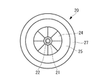
本実施形態の燃焼バーナ20は、例えば図3及び図4に示すように構成されている。図中の符号21は、燃料の重質油を微粒化して火炉11内へ噴射投入する重質油噴霧器(燃料噴霧器)である。この重質油噴霧器21の先端部には、微粒化流体として導入する噴霧用蒸気の圧力によって重質油燃料を微粒化して噴出するため、複数の噴出孔22aを有するオイルアトマイザ22が設けられている。
Next, a configuration example of the
The
また、重質油噴霧器21の外周には、空気取入孔23aを有するハウジングチューブ23が設けられ、その先端部外面には、すなわちオイルアトマイザ22の近傍には、一次空気(図中の矢印A1)を旋回させて供給するためのスワラー24が円周方向に複数設けられている。
ハウジングチューブ23及びスワラー24の周囲は、二次空気(図中の矢印A2)の空気通路25を形成するため、筒状のバーナスロート26で覆われている。さらに、バーナスロート26の外周には、三次空気(図中の矢印A3)を供給する空気通路27が設けられており、この空気通路27内には可変式空気ダンパ28を装備している。
Further, a
The periphery of the
このような構成の燃焼バーナ20において、燃料の重質油及び噴霧用蒸気は、重質油噴霧器21の内部を通って先端部のオイルアトマイザ22に至り、例えば径の異なる大小複数の噴出孔22aから重質油を微粒化した混合流体が所定の方向(例えば斜め前方)へ噴出される。この混合流体は、ハウジングチューブ23内を通ってくる燃焼用空気及びスワラー24によって旋回しながら供給される一次空気と最初に接触し、互いに混合しつつ火炎域を形成する。
In the
一方、スワラー24とバーナスロート26との隙間を通過してくる二次空気、及びバーナスロート26の外側より供給される三次空気は、一次空気による火炎領域より逸脱した未燃分と混合しつつ、主火炎下流部に安定した火炎域を形成する。
このとき、火炎の状態と、排ガス中のNOx濃度及び酸素濃度とに応じて、可変式空気ダンパ28の開度操作をして、三次空気の供給量を調節する。なお、NOx濃度及び酸素濃度は、煙道31の後部適所に設けられた図示しないNOx濃度計及び酸素濃度計の計測値である。
On the other hand, the secondary air passing through the gap between the swirler 24 and the
At this time, according to the state of the flame and the NOx concentration and oxygen concentration in the exhaust gas, the opening degree of the
さて、上述した構成の燃焼バーナ20を備えた重質油焚きボイラ10において、本実施形態では、以下に説明する燃焼方法を採用する。
すなわち、本実施形態では、燃焼バーナ20の重質油噴霧器21に重質油燃料及び微粒化流体の蒸気を導入して混合し、微粒化された重質油噴霧粒子を含む混合流体を燃焼用空気とともに火炉11内へ噴射投入して燃焼させる重質油焚きボイラ10において、重質油燃料として残留炭素分が10%以上となる燃料油を含む複数の油種を同時に燃焼させる。なお、以下に説明する本実施形態では、2種類の重質油燃料(燃料油A,燃料油B)を使用するものとし、一方が相対的に燃料油Bより燃焼性の悪い(低い)燃料油Aであり、他方が相対的に燃料油Aより燃焼性の良い(高い)燃料油Bである。
Now, in the heavy oil fired
That is, in the present embodiment, the heavy oil fuel and the atomized fluid vapor are introduced into and mixed with the
そして、火炉11の上下方向に複数段が配置されている燃焼バーナ20から各々噴射投入される重質油噴霧粒子は、上段側の燃焼バーナ20から燃料油Bの重質油噴霧粒子が噴射投入され、かつ、下段側の燃焼バーナ20から燃料油Aの重質油噴霧粒子が噴射投入されるようになっている。この結果、上段側の燃焼バーナ20から噴射投入される重質油噴霧粒子の燃焼性は、下段側の燃焼バーナ20から噴射投入される重質油噴霧粒子の燃焼性より高くなる。
The heavy oil spray particles injected and injected from the
図示の構成例では、上下方向に5段の燃焼バーナ20が配置され、各段には、例えば周方向に沿って4個が均等間隔で配設されている。さらに、図示の構成例では、下段側2段の燃焼バーナ20(以下、「下段バーナ20N」と呼ぶ)に燃料油Aが供給され、かつ、上段側3段の燃焼バーナ(以下、「上段バーナ20P」と呼ぶ)20に燃料油Bが供給されている。従って、上下方向に5段配置された燃焼バーナ20は、下側2段の下段バーナ20Nから燃焼性の低い重質油噴霧粒子が噴射投入され、かつ、上側3段の上段バーナ20Pから燃焼性の高い重質油噴霧粒子が噴射投入されるが、例えば下側3段の下段バーナ20Nから燃焼性の低い重質油噴霧粒子が噴射投入し、かつ、上側2段の上段バーナ20Pから燃焼性の高い重質油噴霧粒子を噴射投入するなど、特に限定されることはない。
In the illustrated configuration example, five stages of
この結果、下段側2段の下段バーナ20Nから噴射投入された燃焼性の低い燃料油Aの重質油噴霧粒子は、上段側3段の上段バーナ20Pから噴射投入された燃焼性の高い燃料油Bの重質油噴霧粒子と比較して、火炉11内における重質油噴霧粒子の粒子軌跡が長くなるので、火炉内の滞留時間も長くなる。具体的には、下段バーナ20Nから噴射投入された燃料油Aの重質油噴霧粒子は、図1に実線で示すような粒子軌跡を経て燃焼する。このため、燃料油Aの重質油噴霧粒子は、図1に破線で示すような粒子軌跡を経て燃焼する燃料油Bの重質油粒子と比較して、粒子軌跡が長い分だけ火炉11内の滞留時間も長くなる。こうして火炉11内の滞留時間が延長された燃料油Aの重質油粒子は、その燃焼時間も長くなる。
As a result, the heavy oil spray particles of the low combustibility fuel oil A injected from the
従って、燃焼性の異なる2種類の燃料油A及び燃料油Bを火炉11内で同時に燃焼させる場合には、滞留時間及び燃焼時間の長い下段バーナ20Nから燃焼性の低い燃料油Aの重質油噴霧粒子を噴霧投入し、かつ、滞留時間及び燃焼時間の短い上段バーナ20Pから燃焼性の高い燃料油Bの重質油噴霧粒子を噴霧投入することにより、ボイラ出口に到達するまでの間に燃焼しないで未燃分となりやすい燃焼性の低い燃料油Aの重質油噴霧粒子に対して、長い火炉内滞留時間及び燃焼時間が確保されるため、ボイラ出口における煤塵量の増加を抑制することができる。
Therefore, when two types of fuel oil A and fuel oil B having different combustibility are burned simultaneously in the
図2は、重質油噴霧粒子の燃焼プロセスを示す説明図であり、横軸を炉内滞留時間として、縦軸に燃料重量を示している。すなわち、図2は、上述した2種類の燃料油A及び燃料油Bについて、同じ炉内滞留時間の経過に伴う燃料重量の変化を示している。
同じ燃料重量の燃料油A及び燃料油Bは、火炉11内へ噴射投入された炉内滞留時間の初期段階において、高温の火炉11内で噴霧液滴が蒸発及び熱分解する。こうして発生した揮発分が燃焼し、チャーが残ることとなる。このような揮発分の燃焼は、燃焼性の高い燃料油Bで顕著(燃料重量の減少変化が大)となるため、換言すれば、燃焼性の高い燃料油Bが揮発分を多く含んでいるため、チャー収率は燃料油Bのβが燃料油Aのαより低くなる。
FIG. 2 is an explanatory diagram showing a combustion process of heavy oil spray particles, in which the horizontal axis represents the residence time in the furnace, and the vertical axis represents the fuel weight. That is, FIG. 2 shows the change in the fuel weight with the passage of the same residence time in the two types of fuel oil A and fuel oil B described above.
The fuel oil A and the fuel oil B having the same fuel weight are vaporized and thermally decomposed in the high-
このチャー収率は、投入された燃料重量に対するチャーの重量割合である。このようなチャー収率は、従来から重質油燃焼性の一次評価に用いられており、燃焼性の高い燃料油ほど揮発分の割合が多いため、小さな値となる傾向にある。 This char yield is the weight ratio of char to the weight of fuel charged. Such char yield has been conventionally used for primary evaluation of heavy oil combustibility, and fuel oil with higher combustibility tends to be a small value because the proportion of volatile matter is larger.
揮発分の発生・燃焼後には、残ったチャーの燃焼が進行する。このようなチャーの燃焼は、炉内滞留時間においてボイラ出口に到達するまで進行する。
図示の例では、燃料油Aの場合、チャー収率αの状態からチャーの燃焼が進行し、投入された燃料重量に対するボイラ出口の未燃分重量割合がαmの状態で排出される。一方、燃料油Bの場合、チャー収率βの状態からチャーの燃焼が進行し、投入された燃料重量に対するボイラ出口の未燃分重量割合がβmの状態で排出される。なお、チャー収率α,βから未燃分重量割合αm,βmに至るまでの炉内滞留時間内において、燃料重量が変化する傾きを燃料油毎に異なるチャー燃焼特性と呼ぶ。
After the volatile matter is generated and burned, the remaining char burns. Such char combustion proceeds until reaching the boiler outlet during the residence time in the furnace.
In the illustrated example, in the case of the fuel oil A, the combustion of the char proceeds from the state of the char yield α, and is discharged in a state where the unburned portion weight ratio of the boiler outlet to the injected fuel weight is αm. On the other hand, in the case of the fuel oil B, the combustion of the char proceeds from the state of the char yield β, and is discharged in a state where the unburned fuel weight ratio at the boiler outlet with respect to the injected fuel weight is βm. Note that the slope of change in the fuel weight within the furnace residence time from the char yields α, β to the unburned component weight ratios αm, βm is referred to as char combustion characteristics that differ for each fuel oil.
ところで、上述した重質油の燃焼性は、すなわち、重質油噴霧粒子の燃焼性は、チャー収率及びチャーの燃焼速度から下記の数式に基づいて算出される燃焼性評価指標の大小から高低(良し悪し)を判断するとよい。この場合、燃焼評価指標が大きいと、重質油噴霧粒子の燃焼性は低いと評価される。
この数式では、上述したチャー収率に加えて、チャーの燃焼速度を加味して燃焼性評価指標を算出する。ここで使用するチャー収率は、工業分析における残留炭素の収率を用いることもできるが、例えばキュリーポイントパイロラーザーのような急速熱分解装置により値を得ることができれば、より精度を上げることができる。また、燃焼速度は、例えば示差熱重量測定装置によるチャー燃焼特性試験により得られる値である。すなわち、この燃焼速度は、図2に基づいて説明した燃料油毎に異なるチャー燃焼特性であり、炉内滞留時間内においてチャー収率α,βから未燃分重量割合αm,βmに至る燃料重量の変化(傾き)である。
なお、この場合の燃焼速度は、平均燃焼速度を用いているが、チャーの燃え残り(燃焼率が1に近い領域)の燃焼速度を用いてもよい。
In this formula, in addition to the above-mentioned char yield, a combustibility evaluation index is calculated taking into account the combustion rate of char. The char yield used here can be the yield of residual carbon in industrial analysis, but if the value can be obtained by a rapid pyrolysis device such as Curie Point Pyrolaser, the accuracy will be improved. Can do. The burning rate is a value obtained by, for example, a char burning characteristic test using a differential thermogravimetry apparatus. That is, this combustion rate is a char combustion characteristic that is different for each fuel oil described based on FIG. 2, and the fuel weight from char yield α, β to unburned component weight ratio αm, βm within the residence time in the furnace. Change (slope).
In addition, although the average burning rate is used for the burning rate in this case, the burning rate of the unburned char (region where the burning rate is close to 1) may be used.
従って、図2に示す燃焼プロセスにおいて、燃焼性の低い燃料油Aの炉内滞留時間を長くすれば、未燃分重量割合を低下させて燃料油Bに近づけることができる。すなわち、燃料油Aの炉内滞留時間を長くすることは、図2におけるボイラ出口を右側に移動させることを意味するので、炉内滞留時間の延長に応じて、未燃分重量割合αmをαnまで低下させることが可能になる。 Therefore, in the combustion process shown in FIG. 2, if the residence time of the low-combustible fuel oil A in the furnace is lengthened, the unburnt weight ratio can be reduced to approach the fuel oil B. That is, increasing the residence time of the fuel oil A in the furnace means moving the boiler outlet in FIG. 2 to the right side, so that the unburned weight ratio αm is changed to αn according to the extension of the residence time in the furnace. Can be reduced to
また、チャー燃焼速度(燃焼特性)を考慮した燃焼評価指標を採用すれば、チャーの残留量だけでなく、チャーの質を意味する燃焼性(炉内滞留時間内で燃焼するチャーの量)も反映させた評価が可能になるので、各重質油噴霧粒子の燃焼性に関する評価精度はより一層向上したものとなる。
なお、炉内滞留時間延長後における燃料油Aの未燃分割合αnは、燃料油A及び燃料油Bのチャー燃焼特性や延長時間等に応じて、燃料油Bの未燃分割合βnと同じになる場合だけでなく、諸条件によっては逆転して未燃分割合βnより低下する場合もある。
In addition, if a combustion evaluation index that takes into account the char combustion rate (combustion characteristics) is adopted, not only the amount of remaining char but also the combustibility (the amount of char that burns within the residence time in the furnace) means the quality of char. Since the reflected evaluation becomes possible, the evaluation accuracy regarding the combustibility of each heavy oil spray particle is further improved.
The unburned fraction ratio αn of the fuel oil A after extending the residence time in the furnace is the same as the unburned fraction ratio βn of the fuel oil B depending on the char combustion characteristics of the fuel oil A and the fuel oil B, the extended time, and the like. In some cases, depending on various conditions, it may reverse and fall below the unburned fraction βn.
また、こうしてボイラ出口における煤塵量の増加を抑制できれば、煤塵対策を目的として燃料油の微粒化に用いる蒸気等の微粒化流体(噴霧媒体)を増量する必要がなくなり、この結果、煤塵対策を目的とする微粒化流体の消費率増加を抑制できる。
そして、燃焼性の異なる重質油を3種類以上同時に燃焼させる場合には、最も燃焼性の低い重質油の重質油噴霧粒子を下段側に位置する1または複数段の燃焼バーナ20から噴射投入し、最も燃焼性の高い重質油の重質油噴霧粒子を上段側に位置する1または複数段の燃焼バーナ20から噴射投入するように、下段側にある1または複数段の燃焼バーナ20から上段側にある1または複数段の燃焼バーナ20へ向けて、噴射投入される重質油噴霧粒子の燃焼性を順次高くすればよい。すなわち、3種類の重質油を同時に燃焼させる場合には、下段領域、中段領域及び上段領域の順に、燃焼バーナ20から噴射投入する重質油噴霧粒子の燃焼性を高くしていけばよい。
If the increase in the amount of dust at the boiler outlet can be suppressed in this way, it is not necessary to increase the amount of atomized fluid (spray medium) such as steam used for atomization of fuel oil for the purpose of dust control. An increase in the consumption rate of the atomized fluid can be suppressed.
When three or more kinds of heavy oils having different flammability are burned simultaneously, heavy oil spray particles of heavy oil having the lowest flammability are injected from one or more stages of
このように、上述した本実施形態によれば、重質油燃料として残留炭素分が10%以上となる燃料油を含む複数の油種を同時に燃焼させる重質油焚きボイラ10においては、火炉11内の粒子軌跡(滞留時間)を有効利用して燃焼性の低い燃料を可能な限り長く燃焼させることにより、すなわち、燃焼性の低い重質油燃料の重質油噴霧粒子を下段側の燃焼バーナ20から噴射投入して長い炉内滞留時間を確保することにより、蒸気等の微粒化流体消費率を増加させることなく、ボイラ出口から排出される煤塵量を抑制することが可能になる。このような本実施形態の重質油焚きボイラ10及びその燃焼方法は、旋回燃焼方式や対向燃焼方式のボイラに適用可能である。
なお、本発明は上述した実施形態に限定されることはなく、たとえば微粒化流体として空気の利用が可能であるなど、その要旨を逸脱しない範囲内において適宜変更することができる。
Thus, according to the present embodiment described above, in the heavy oil-fired
In addition, this invention is not limited to embodiment mentioned above, For example, utilization of air is possible as atomization fluid, For example, it can change suitably in the range which does not deviate from the summary.
10 重質油焚きボイラ
11 火炉
12 燃焼装置
13 燃料供給配管
14 蒸気供給配管
20 燃焼バーナ
20N 下段バーナ
20P 上段バーナ
21 重質油噴霧器(燃料噴霧器)
22 オイルアトマイザ
24 スワラー
31 煙道
DESCRIPTION OF
22
Claims (6)
前記重質油燃料として残留炭素分が10%以上となる燃料油を含む複数の油種を同時に燃焼させ、
前記火炉の上下方向に複数段配置されている前記燃焼バーナから各々噴射投入される前記重質油噴霧粒子について、上段側に配置した1または複数段の前記燃焼バーナから噴射投入される前記重質油噴霧粒子の燃焼性が、下段側に配置した1または複数段の前記燃焼バーナから噴射投入される前記重質油噴霧粒子の燃焼性より高く設定され、
前記燃焼性の高低は、揮発分の割合に基づいて判断されることを特徴とする重質油焚きボイラの燃焼方法。 Heavy oil fuel and atomized fluid are introduced and mixed in the fuel sprayer of the combustion burner, and the mixed fluid containing the atomized heavy oil spray particles is injected into the furnace together with combustion air and burned. A method for burning an oil fired boiler,
Combusting a plurality of oil types including fuel oil having a residual carbon content of 10% or more as the heavy oil fuel,
The heavy oil spray particles injected from the combustion burners arranged in a plurality of stages in the vertical direction of the furnace are injected from the combustion burner of one or more stages arranged on the upper stage side. The combustibility of the oil spray particles is set higher than the combustibility of the heavy oil spray particles injected from one or more stages of the combustion burner arranged on the lower stage side ,
The combustion of the high and low, heavy oil-fired boiler combustion method, characterized in Rukoto is determined based on the percentage of volatile matter.
前記重質油燃料として残留炭素分が10%以上となる燃料油を含む複数の油種を同時に燃焼させ、
前記火炉の上下方向に複数段配置されて各々前記重質油噴霧粒子を噴射投入する前記燃焼バーナは、上段側に配置された1または複数段の上段バーナと下段側に配置された1または複数段の下段バーナとを備え、前記上段バーナから噴射投入される前記重質油噴霧粒子の燃焼性が、前記下段バーナから噴射投入される前記重質油噴霧粒子の燃焼性より高く設定され、
前記燃焼性の高低は、揮発分の割合に基づいて判断されていることを特徴とする重質油焚きボイラ。 Heavy oil fuel and atomized fluid are introduced and mixed in the fuel sprayer of the combustion burner, and the mixed fluid containing the atomized heavy oil spray particles is injected into the furnace together with combustion air and burned. An oil-fired boiler,
Combusting a plurality of oil types including fuel oil having a residual carbon content of 10% or more as the heavy oil fuel,
The combustion burner, which is arranged in a plurality of stages in the vertical direction of the furnace and injects and inputs the heavy oil spray particles, respectively, is one or more upper burners arranged on the upper stage side and one or more arranged on the lower stage side. A lower burner of the stage, the combustion property of the heavy oil spray particles injected from the upper burner is set higher than the combustion property of the heavy oil spray particles injected from the lower burner ,
The heavy oil-fired boiler characterized in that the level of flammability is determined based on the ratio of volatile matter.
前記重質油燃料として残留炭素分が10%以上となる燃料油を含む複数の油種を同時に燃焼させ、Combusting a plurality of oil types including fuel oil having a residual carbon content of 10% or more as the heavy oil fuel,
前記火炉の上下方向に複数段配置されている前記燃焼バーナから各々噴射投入される前記重質油噴霧粒子について、上段側に配置した1または複数段の前記燃焼バーナから噴射投入される前記重質油噴霧粒子の燃焼性が、下段側に配置した1または複数段の前記燃焼バーナから噴射投入される前記重質油噴霧粒子の燃焼性より高く設定され、The heavy oil spray particles injected from the combustion burners arranged in a plurality of stages in the vertical direction of the furnace are injected from the combustion burner of one or more stages arranged on the upper stage side. The combustibility of the oil spray particles is set higher than the combustibility of the heavy oil spray particles injected from one or more stages of the combustion burner arranged on the lower stage side,
前記燃焼性の高低は、The level of flammability is
前記重質油燃料として残留炭素分が10%以上となる燃料油を含む複数の油種を同時に燃焼させ、Combusting a plurality of oil types including fuel oil having a residual carbon content of 10% or more as the heavy oil fuel,
前記火炉の上下方向に複数段配置されて各々前記重質油噴霧粒子を噴射投入する前記燃焼バーナは、上段側に配置された1または複数段の上段バーナと下段側に配置された1または複数段の下段バーナとを備え、前記上段バーナから噴射投入される前記重質油噴霧粒子の燃焼性が、前記下段バーナから噴射投入される前記重質油噴霧粒子の燃焼性より高く設定され、The combustion burner, which is arranged in a plurality of stages in the vertical direction of the furnace and injects and inputs the heavy oil spray particles, respectively, is one or more upper burners arranged on the upper stage side and one or more arranged on the lower stage side. A lower burner of the stage, the combustion property of the heavy oil spray particles injected from the upper burner is set higher than the combustion property of the heavy oil spray particles injected from the lower burner,
前記燃焼性の高低は、The level of flammability is
Priority Applications (1)
| Application Number | Priority Date | Filing Date | Title |
|---|---|---|---|
| JP2014254198A JP6466157B2 (en) | 2014-12-16 | 2014-12-16 | Heavy oil-fired boiler combustion method and heavy oil-fired boiler |
Applications Claiming Priority (1)
| Application Number | Priority Date | Filing Date | Title |
|---|---|---|---|
| JP2014254198A JP6466157B2 (en) | 2014-12-16 | 2014-12-16 | Heavy oil-fired boiler combustion method and heavy oil-fired boiler |
Publications (2)
| Publication Number | Publication Date |
|---|---|
| JP2016114316A JP2016114316A (en) | 2016-06-23 |
| JP6466157B2 true JP6466157B2 (en) | 2019-02-06 |
Family
ID=56141463
Family Applications (1)
| Application Number | Title | Priority Date | Filing Date |
|---|---|---|---|
| JP2014254198A Active JP6466157B2 (en) | 2014-12-16 | 2014-12-16 | Heavy oil-fired boiler combustion method and heavy oil-fired boiler |
Country Status (1)
| Country | Link |
|---|---|
| JP (1) | JP6466157B2 (en) |
Families Citing this family (2)
| Publication number | Priority date | Publication date | Assignee | Title |
|---|---|---|---|---|
| US20160223196A1 (en) * | 2015-02-02 | 2016-08-04 | The Government Of The United States Of America, As Represented By The Secretary Of The Navy | Crude Oil Spray Combustor |
| KR101839213B1 (en) * | 2016-07-11 | 2018-03-15 | 한국서부발전 주식회사 | Pressure-refined oil combustion device for power plant |
Family Cites Families (3)
| Publication number | Priority date | Publication date | Assignee | Title |
|---|---|---|---|---|
| JPS63180004A (en) * | 1987-01-21 | 1988-07-25 | Mitsubishi Kasei Corp | Combustion method of boiler |
| JPS6441701A (en) * | 1987-08-06 | 1989-02-14 | Mitsubishi Heavy Ind Ltd | Method of burning pulverized coal |
| JP2000356307A (en) * | 1999-06-16 | 2000-12-26 | Babcock Hitachi Kk | Multi-fuel combustion burner for different kinds of liquid fuels and combustor having the burner |
-
2014
- 2014-12-16 JP JP2014254198A patent/JP6466157B2/en active Active
Also Published As
| Publication number | Publication date |
|---|---|
| JP2016114316A (en) | 2016-06-23 |
Similar Documents
| Publication | Publication Date | Title |
|---|---|---|
| CN107355776B (en) | Combustion System of Boiler Burning Fine, method and the application of ultra-low NOx emission | |
| CN110056873A (en) | A kind of low nitrogen combustion apparatus suitable for fuel gas with low heat value | |
| JP6466157B2 (en) | Heavy oil-fired boiler combustion method and heavy oil-fired boiler | |
| KR101019516B1 (en) | Low nox high efficiency burner nozzle for liquid fuel and burning equipment using the burner nozzle | |
| CN202149495U (en) | Burner | |
| KR100973414B1 (en) | Coal breeze burner unnecessary preheating | |
| KR101810831B1 (en) | an eletric heating element for nozzled spray droplet and the liquid fuel spraying and mixing device uisng both multistage-perforated heating plate and an eletric heating element | |
| CN201137933Y (en) | Low NOx coal fines thick and thin oil-saving burner | |
| CN110160050B (en) | Biomass gasification gas and pulverized coal co-combustion low-nitrogen combustor | |
| CN102072494B (en) | Combustor | |
| US10378758B2 (en) | Burner tip, combustion burner, and boiler | |
| JP6270468B2 (en) | Heavy oil-fired boiler combustion method and heavy oil-fired boiler | |
| CN104302976B (en) | System And Method For Small-Scale Combustion Of Pulverized Solid Fuels | |
| JP6448902B2 (en) | Heavy oil-fired boiler combustion method and heavy oil-fired boiler | |
| CN102032563B (en) | Pulverized coal burner and boiler with same | |
| DK3034942T3 (en) | Bio-oil burner and oil nozzle | |
| CN206958924U (en) | A kind of steam boiler plant low Nox oil and gas combination burner | |
| CN201916920U (en) | Fuel oil gasification device and plasma fuel oil gasification composite pulverized coal burner | |
| CN206958900U (en) | A kind of Researched of Air Staging Combustion Burning Pulverized Coal device | |
| CN101709876B (en) | Special combustor for petroleum coke powder | |
| US20170138634A1 (en) | Method and Apparatus for Firetube Boiler and Ultra Low NOx Burner | |
| CN103307595B (en) | It is a kind of to extend the application method that small and medium-sized industrial coal powder boilers are applicable the device of coal | |
| JP2012241971A (en) | Biomass combusting boiler | |
| CN101413660B (en) | Heavy oil and low-oil-consumption ignition coal powder combustor | |
| RU2262039C2 (en) | Method of combustion of hydrocarbon fuel and device for realization of this method (versions) |
Legal Events
| Date | Code | Title | Description |
|---|---|---|---|
| A625 | Written request for application examination (by other person) |
Free format text: JAPANESE INTERMEDIATE CODE: A625 Effective date: 20171215 |
|
| A131 | Notification of reasons for refusal |
Free format text: JAPANESE INTERMEDIATE CODE: A131 Effective date: 20180717 |
|
| A977 | Report on retrieval |
Free format text: JAPANESE INTERMEDIATE CODE: A971007 Effective date: 20180720 |
|
| A521 | Written amendment |
Free format text: JAPANESE INTERMEDIATE CODE: A523 Effective date: 20180918 |
|
| TRDD | Decision of grant or rejection written | ||
| A01 | Written decision to grant a patent or to grant a registration (utility model) |
Free format text: JAPANESE INTERMEDIATE CODE: A01 Effective date: 20181211 |
|
| A61 | First payment of annual fees (during grant procedure) |
Free format text: JAPANESE INTERMEDIATE CODE: A61 Effective date: 20190109 |
|
| R150 | Certificate of patent or registration of utility model |
Ref document number: 6466157 Country of ref document: JP Free format text: JAPANESE INTERMEDIATE CODE: R150 |
|
| S533 | Written request for registration of change of name |
Free format text: JAPANESE INTERMEDIATE CODE: R313533 |
|
| R350 | Written notification of registration of transfer |
Free format text: JAPANESE INTERMEDIATE CODE: R350 |