JP2012241971A - Biomass combusting boiler - Google Patents
Biomass combusting boiler Download PDFInfo
- Publication number
- JP2012241971A JP2012241971A JP2011111936A JP2011111936A JP2012241971A JP 2012241971 A JP2012241971 A JP 2012241971A JP 2011111936 A JP2011111936 A JP 2011111936A JP 2011111936 A JP2011111936 A JP 2011111936A JP 2012241971 A JP2012241971 A JP 2012241971A
- Authority
- JP
- Japan
- Prior art keywords
- biomass
- furnace
- fluid
- boiler
- tube
- Prior art date
- Legal status (The legal status is an assumption and is not a legal conclusion. Google has not performed a legal analysis and makes no representation as to the accuracy of the status listed.)
- Granted
Links
Images

Landscapes
- Combustion Of Fluid Fuel (AREA)
- Incineration Of Waste (AREA)
Abstract
【課題】本発明の目的は、バイオマス燃焼ボイラの火炉のボトムホッパに堆積したバイオマス未燃分を減少させて、ボイラの安全性と燃焼効率を共に向上させるバイオマス燃焼ボイラを提供する。
【解決手段】バイオマスを燃料として燃焼し、燃焼により発生した熱で蒸気を発生させるバイオマス燃焼ボイラであって、ボイラの火炉上部には燃焼により発生した熱を蒸気に伝える伝熱管が設けられており、ボイラの火炉底部にはボトムホッパを有し、ボイラの火炉下部にはバイオマスを燃焼させる多段のバーナが設置され、前記多段のバーナの最下段バーナよりも低い位置の火炉壁面に開口部を設け、流体を噴霧する噴射口を備えた流体噴霧装置を前記開口部から火炉内へ挿入可能に設置し、前記流体噴霧装置から火炉の底部のボトムホッパに向けて不燃性の流体を噴霧するように構成した。
【選択図】図3An object of the present invention is to provide a biomass combustion boiler that reduces both unburned biomass accumulated in a bottom hopper of a furnace of a biomass combustion boiler and improves both safety and combustion efficiency of the boiler.
SOLUTION: A biomass combustion boiler that burns biomass as fuel and generates steam with the heat generated by the combustion, and is provided with a heat transfer tube that transmits heat generated by the combustion to the steam at the upper part of the furnace of the boiler. A bottom hopper at the bottom of the furnace of the boiler, a multi-stage burner for burning biomass is installed at the bottom of the furnace of the boiler, and an opening is provided on the furnace wall at a position lower than the lowest burner of the multi-stage burner, A fluid spraying device having an injection port for spraying a fluid is installed so as to be insertable into the furnace from the opening, and configured to spray nonflammable fluid from the fluid spraying device toward a bottom hopper at the bottom of the furnace. .
[Selection] Figure 3
Description
本発明は、バイオマス燃料を燃焼させるバイオマス燃焼ボイラ、及び微粉炭とバイオマスを混合燃焼させるバイオマス燃焼ボイラに関するものである。 The present invention relates to a biomass combustion boiler that burns biomass fuel, and a biomass combustion boiler that mixes and burns pulverized coal and biomass.
産業用ボイラ、事業用ボイラ、各種タービンなど、燃焼によりエネルギーを生産する装置においては、燃料として石炭や重油等の化石燃料が用いられることが多い。近年、地球温暖化の観点からCO2排出量の削減が推進されているため、CO2を多く排出し、地球温暖化を促進する化石燃料は、地球環境保全の見地からその使用が規制されつつある。 In apparatuses that produce energy by combustion, such as industrial boilers, business boilers, and various turbines, fossil fuels such as coal and heavy oil are often used as fuel. In recent years, since the reduction of CO2 emissions in terms of global warming has been promoted, the CO 2 much discharged, fossil fuels to promote global warming, while their use is restricted from the standpoint of global environmental conservation .
そのため、化石燃料の代替として、バイオマスの利用促進が図られている。バイオマスには、木質系、草木系、汚泥系等の分類があり、クリーンかつ再生利用可能な炭素質資源である。このバイオマスを燃料化処理することで、エネルギー源又は工業原料として有効に利用することができる。 Therefore, the use of biomass is promoted as an alternative to fossil fuels. Biomass is classified as woody, vegetation, or sludge, and is a clean and recyclable carbonaceous resource. By using this biomass as a fuel, it can be effectively used as an energy source or an industrial raw material.
バイオマス燃料は、乾燥により着火性、燃焼性が格段に向上するが、石炭のような脆性材料でないために、石炭と比較して微粒化、微粉化が困難である。従来の石炭燃焼装置で使用している微粉炭の平均粒径は数十μmであるのに対し、バイオマス燃料は、石炭を微粉化する粉砕装置と同等以上の粉砕能力を持つ装置を用いても、微粉化の程度は平均粒径が1mm程度である。 Biomass fuel is significantly improved in ignitability and combustibility by drying, but is not a brittle material such as coal, so it is difficult to atomize and pulverize compared to coal. While the average particle size of pulverized coal used in conventional coal combustion equipment is several tens of μm, biomass fuel can be used even with equipment that has a pulverization capacity equivalent to or better than that of pulverization equipment that pulverizes coal. The degree of pulverization is about 1 mm in average particle size.
従って、バイオマスそれ自体は、乾燥すれば着火性、燃焼性は十分に良いが、粒径が大きいため、燃料として燃焼装置に大量に供給する場合には、石炭粒子に比べて着火性が悪くなる。そのため、燃焼炉内でバイオマス燃料の未燃分が増加し、炉内のCO、NOx濃度が高くなるという問題が生じる。 Therefore, the biomass itself is sufficiently good in ignitability and combustibility if dried, but because of its large particle size, when it is supplied in large quantities as a fuel to the combustion device, it becomes less ignitable than coal particles. . Therefore, there arises a problem that the unburned portion of the biomass fuel increases in the combustion furnace, and the CO and NOx concentrations in the furnace increase.
また、バイオマス燃料は粒径が大きいため、燃焼炉に供給された後、浮遊できずに落下する。このバイオマスの火炉底部への落下のため、燃焼効率が低下するという問題が生じる。 Moreover, since the biomass fuel has a large particle size, it falls without being able to float after being supplied to the combustion furnace. Due to the fall of the biomass to the bottom of the furnace, there arises a problem that the combustion efficiency is lowered.
バイオマス燃料の未燃分および落下を防ぐために、これまでに多くの方法が提案されている。 Many methods have been proposed so far to prevent unburned and falling biomass fuel.
例えば、特開2007−101135号公報に開示された技術では、バイオマスを燃焼するバーナを、微粉炭を燃焼するバーナよりも上方に配置し、微粉炭バーナの火炎の吹き上がりを利用してバイオマス燃料の炉内の浮遊時間を長くしている。 For example, in the technology disclosed in Japanese Patent Application Laid-Open No. 2007-101135, biomass fuel is burned by placing a burner that burns biomass above a burner that burns pulverized coal, and using the blow-up of the flame of the pulverized coal burner. The floating time in the furnace is increased.
浮遊時間の延長により、大粒径のバイオマス燃料でも火炉底部まで降下した時には完全に灰になっているのが理想であるが、完全に燃え尽きて灰になるのは粒度が3〜5mm未満である。これ以上の粒子は、揮発分、水分を放出し、一部固定炭素分の燃焼も起こるが、かなりの割合の未燃分が火炉底部に落下し、ボトムホッパに堆積する。 Ideally, even with large particle size biomass fuel, when it descends to the bottom of the furnace due to the extension of the floating time, it is ideally completely ash, but it is less than 3-5mm in size when it burns completely and becomes ash. . More particles release volatiles and moisture, and some of the fixed carbon also burns, but a significant proportion of unburned material falls to the bottom of the furnace and accumulates in the bottom hopper.
ボイラ通常運転では、火炉底部の温度が低く、堆積したバイオマス燃料は燃焼しきれない。このため、ボトムホッパへのバイオマス未燃分の堆積量は時間と共に増加する。ボイラ機器の異常によって炉内のガス濃度分布や温度の変動が生じた場合、堆積した大量のバイオマス未燃分は急激に燃焼を開始し、火炉底部の熱負荷の上昇によって炉壁破損に至る可能性がある。 In normal boiler operation, the temperature at the bottom of the furnace is low and the accumulated biomass fuel cannot be combusted. For this reason, the amount of unburned biomass on the bottom hopper increases with time. When the gas concentration distribution or temperature in the furnace changes due to an abnormality in the boiler equipment, a large amount of unburned biomass begins to burn rapidly, and the furnace wall may be damaged due to an increase in the thermal load at the bottom of the furnace. There is sex.
前記特開2007−101135号公報に記載した微粉炭とバイオマスを混合燃焼させるバイオマス燃焼ボイラや、バイオマス燃料を燃焼させるバイオマス燃焼ボイラでは、バイオマス燃料の利用を促進するためにバイオマス燃料のボイラ火炉への供給量を増やす必要がある。 In a biomass combustion boiler that mixes and burns pulverized coal and biomass described in JP 2007-101135 A and a biomass combustion boiler that burns biomass fuel, in order to promote the use of biomass fuel, the biomass fuel is supplied to the boiler furnace. It is necessary to increase the supply amount.
しかしながら、上記バイオマス燃焼ボイラではバイオマス燃料の供給量を増やすと、ボイラ火炉のボトムホッパにバイオマス未燃分が大量に堆積することが避けられない。そしてボイラ機器に何らかの異常に起因して火炉内のガス濃度分布や温度の変動が生じ、ボトムホッパに堆積した大量のバイオマス未燃分が急激に燃焼した場合には、火炉底部の熱負荷の上昇によって炉壁破損に至る可能性がある。 However, when the biomass fuel supply amount is increased in the biomass combustion boiler, it is inevitable that a large amount of unburned biomass accumulates in the bottom hopper of the boiler furnace. And if there is a fluctuation in the gas concentration distribution or temperature in the furnace due to some abnormality in the boiler equipment, and a large amount of unburned biomass accumulated in the bottom hopper burns rapidly, an increase in the thermal load at the bottom of the furnace It may lead to furnace wall damage.
本発明の目的は、燃料としてバイオマス燃料を燃焼させる場合に、バイオマス燃焼ボイラの火炉のボトムホッパに堆積したバイオマス未燃分を減少させて、ボイラの安全性と燃焼効率を共に向上させるバイオマス燃焼ボイラを提供することにある。 An object of the present invention is to provide a biomass combustion boiler that reduces both unburned biomass accumulated in the bottom hopper of a biomass combustion boiler furnace and improves both boiler safety and combustion efficiency when burning biomass fuel as fuel. It is to provide.
本発明のバイオマス燃焼ボイラは、石炭とバイオマス、またはバイオマスのみを燃料として燃焼し、燃焼により発生した熱で蒸気を発生させるバイオマス燃焼ボイラであって、ボイラの火炉上部には燃焼により発生した熱を蒸気に伝える伝熱管が設けられており、ボイラの火炉底部にはボトムホッパを有し、ボイラの火炉下部には石炭とバイオマス、またはバイオマスを燃焼させる多段のバーナが設置され、前記多段のバーナの最下段バーナよりも低い位置の火炉壁面に開口部を設け、流体を噴霧する噴射口を備えた流体噴霧装置を前記開口部から火炉内へ挿入可能に設置し、前記流体噴霧装置から火炉の底部のボトムホッパに向けて不燃性の流体を噴霧するように構成したことを特徴とする。 The biomass combustion boiler of the present invention is a biomass combustion boiler that burns coal and biomass or only biomass as fuel and generates steam by the heat generated by the combustion, and heat generated by the combustion is generated in the upper part of the boiler furnace. A heat transfer tube is provided to transmit steam, and a bottom hopper is provided at the bottom of the boiler furnace, and a multistage burner for burning coal and biomass or biomass is installed at the bottom of the boiler furnace. An opening is provided in the furnace wall surface at a position lower than the lower burner, and a fluid spraying device having an injection port for spraying fluid is installed so as to be inserted into the furnace from the opening, and from the fluid spraying device to the bottom of the furnace It is configured to spray a nonflammable fluid toward the bottom hopper.
本発明によれば、燃料としてバイオマス燃料を燃焼させる場合に、バイオマス燃焼ボイラの火炉のボトムホッパに堆積したバイオマス未燃分を効果的に減少させて、ボイラの安全性と燃焼効率を共に向上させたバイオマス燃焼ボイラを実現することできる。 According to the present invention, when biomass fuel is burned as fuel, the biomass unburned matter accumulated in the bottom hopper of the furnace of the biomass combustion boiler is effectively reduced, and both the safety and the combustion efficiency of the boiler are improved. A biomass combustion boiler can be realized.
次に本発明の実施例であるバイオマス燃焼ボイラについて図面を参照して以下に説明する。 Next, a biomass combustion boiler according to an embodiment of the present invention will be described below with reference to the drawings.
図1を用いて本発明の第1実施例であるバイオマス燃焼ボイラについて説明する。 The biomass combustion boiler which is 1st Example of this invention is demonstrated using FIG.
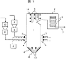
図1に示したように、本実施例のバイオマス燃焼ボイラにおいて、ボイラ本体は火炉1と、火炉1に続く後部伝熱面2とから主に構成されている。火炉1の上部から後部伝熱面2にかけて、過熱器、再熱器、節炭器に該当する伝熱管群5が設置されている。伝熱管群5の周囲には、ボイラ運転中に伝熱管群5に付着した灰を除去するためにスートブロア14が備えられている。
As shown in FIG. 1, in the biomass combustion boiler of this embodiment, the boiler body is mainly composed of a
火炉1の下部の火炉壁面には複数段に亘って微粉炭を燃焼させる微粉炭バーナ3と、燃料としてのバイオマス燃料を燃焼させるバイオマスバーナ4とがそれぞれ設置されており、石炭やバイオマスなどの固体燃料が、燃焼用空気供給手段6から供給される燃焼用空気とともに微粉炭バーナ3、またはバイオマスバーナ4から火炉1内に噴射されて該火炉1の内部にて燃焼する。
A pulverized
そして、火炉1内で石炭やバイオマスなどの固体燃料を燃焼させることによって生成された燃焼ガスは、火炉1から後部伝熱面2を通過する途中で伝熱管群5と熱交換し、これらの伝熱管群5を流下した後に排ガスダクト7を通ってボイラから流下し、下流の排ガス処理設備で排ガス処理された後に大気中に放出される。
And the combustion gas produced | generated by burning solid fuels, such as coal and biomass, in the
また、前記伝熱管群5での熱交換によって発生した高温の蒸気は図示していない蒸気タービンに供給されて該蒸気タービンを駆動する。
The high-temperature steam generated by heat exchange in the heat
前記微粉炭炊きボイラ装置の火炉1に設置された微粉炭バーナ3に供給される微粉炭は、石炭バンカ8から搬送された石炭を石炭ミル9で粉砕して作る。また、火炉1に設置されたバイオマスバーナ3に供給されるバイオマスは、バイオマスバンカ10から搬送されたバイオマスをバイオマスミル11で粉砕して作られる。
The pulverized coal supplied to the pulverized
本実施例のバイオマス燃焼ボイラは、石炭とバイオマスを混合燃焼させるバイオマス燃焼ボイラに限るものではなく、バイオマスのみを火炉内へ供給して燃焼させるバイオマス専焼ボイラにも適用可能である。 The biomass combustion boiler of the present embodiment is not limited to a biomass combustion boiler in which coal and biomass are mixed and burned, and can also be applied to a biomass-fired boiler that supplies only biomass into the furnace and burns it.
本実施例のバイオマス燃焼ボイラでは、火炉1に設置した微粉炭バーナ3よりも低い火炉壁面の位置に、流体噴霧装置12を火炉1内に挿入するための複数の開口部13がそれぞれ設けられている。
In the biomass combustion boiler of the present embodiment, a plurality of
燃料として使用する石炭は石炭バンカ8から石炭ミル9に供給され、数十〜数百μmの粒径に粉砕された後に火炉1の壁面に設置した微粉炭バーナ3から火炉1内に供給されて燃焼する。一方、バイオマス燃料は、バイオマスバンカ10からバイオマスミル11に供給され、数十mm以下の粒径に粉砕され、火炉1の壁面に設置したバイオマスバーナ4から火炉1に供給されて燃焼する。
Coal to be used as fuel is supplied from the
ここでは、バイオマスを単独で粉砕するバイオマスミル11を用いる場合についてのみ説明するが、石炭とバイオマスを混合粉砕する石炭・バイオマス混合ミルを用いてもよい。また、石炭ミル9、バイオマスミル11、石炭・バイオマス混合ミルは、それぞれ複数台使用しても構わない。
Here, only the case of using the
バイオマスバーナ4から火炉1に供給されたバイオマスの内、小粒径のものは火炉内の燃焼ガスで吹き上げられて、排ガスダクト7から火炉外へ排出される。
Of the biomass supplied from the
一方、大粒径のバイオマスは、バイオマスバーナ4から火炉1内に噴出した後に落下し、火炉1の底部のボトムホッパ15に達する。落下中のバイオマスは、微粉炭および小粒径バイオマスの燃焼火炎や輻射熱により燃焼されるため、一部はボトムホッパ15に達するまでに完全に燃え尽きて灰となるが、残りはバイオマス未燃分16としてボトムホッパ15に堆積する。
On the other hand, biomass having a large particle size is ejected from the
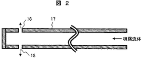
ボトムホッパ15へ堆積したバイオマス未燃分16は、火炉1の壁面に形成した開口部13から火炉1の内部に挿入される流体噴霧装置12によって除去する。ボトムホッパ15に堆積したバイオマス未燃分16の除去方法については、図2、図3を用いて説明する。
The biomass
図2、図3において、本実施例のバイオマス燃焼ボイラに設置された流体噴霧装置12は、内部を流体が流れるチューブ17と、流体を噴霧する噴射口18と、前記チューブ17を回転、かつ挿入方向に沿って前後に移動させる駆動装置(図示せず)から構成されている。
2 and 3, the
また、流体噴霧装置12には、噴射口18から噴霧される流体の圧力および流量を調整可能な圧力調整機構を構成する圧力検出器19と、この圧力検出器19によって検出した流体の圧力および流量を入力して噴射口18から噴霧する流体の圧力および流量を演算し、この演算した流体の圧力および流量の指令信号を圧力調整弁20に出力する圧力調整弁制御装置21と、この力調整弁制御装置21によって操作される前記圧力調整弁20とが備えられている。
Further, the
上記の流体噴霧装置12は、従来の微粉炭ボイラで使用されるスートブロア14と類似の構造であり、スートブロア14を転用して改造してもよい。
The
流体噴霧装置12のチューブ17から噴霧する流体は、蒸気、空気、その他の不燃性流体、あるいはこれら複数の流体の混合流体を用いる。流体噴霧装置12を構成するチューブ17を流れる流体はチューブ17に形成した噴射口18から、火炉1の底部のボトムホッパ15に向けて噴射され、このボトムホッパ15に堆積したバイオマス未燃分16を火炉1内で燃焼させて除去する。
As the fluid sprayed from the
即ち、前記流体噴霧装置12のチューブ17から火炉1の底部のボトムホッパ15に向けて不燃性の流体を噴霧することによって、火炉1の底部のボトムホッパ15に堆積したバイオマス未燃分16は温度の高い火炉1内の上方へ吹き上げられ、バイオマス未燃分16の燃焼が促進される。
That is, by spraying a nonflammable fluid from the
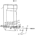
図3は、図1の実施例であるバイオマス燃焼ボイラに用いられる流体噴霧装置12の構成とその操作の状況について説明するものであり、火炉1への流体噴霧装置12のチューブ17を、火炉1内部に挿入した状態を示す斜視図である。
FIG. 3 explains the configuration of the
図3に示した本実施例のバイオマス燃焼ボイラでは、火炉1の壁面を構成する左右の火炉壁に形成した開口部13の近傍に流体噴霧装置12を夫々設置し、左右の火炉壁の両方向から前記開口部13を通じて流体噴霧装置12を構成するチューブ17を火炉1内にそれぞれ挿入する。
In the biomass combustion boiler of the present embodiment shown in FIG. 3, the
前記流体噴霧装置12は、チューブ17に形成した噴射口18がチューブ17の軸を中心に回転できる構造になっており、火炉1の炉壁側から火炉1の中央部までを回転しながら火炉1の中央へ移動する。そしてこのチューブ17に形成した噴射口18から不燃性の流体を火炉1の底部のボトムホッパ15に堆積したバイオマス未燃分16に向けて噴射する。
The
前記流体噴霧装置12を複数設置する場合には、個々の流体噴霧装置12がそれぞれ独立に運転制御が可能となるように構成している。
When a plurality of the
流体噴霧装置12は、流体を噴射するチューブ17を火炉1内に挿入して使用するため、炉内の落下物が少ない時間帯にチューブ17を挿入した方が、チューブ17を破損する可能性が低くなる。炉内の落下物が多くなるのは、スートブロア14の運転中や、プラントの負荷変化中である。
Since the
このため、本実施例の流体噴霧装置12は、火炉1の上部に設置されているスートブロア14を運転されており、プラントの負荷変化が終了して、伝熱管群5への付着物が火炉底部へ落下した後となる時間帯に、火炉1の火炉壁に形成した開口部13を通じて流体噴霧装置12を操作して該流体噴霧装置12のチューブ17を火炉1内に挿入して、このチューブ17の噴射口18から不燃性流体を火炉1底部のボトムホッパ15に堆積したバイオマス未燃分16に向けて噴射するように構成している。
For this reason, the
そしてチューブ17の噴射口18から不燃性の流体を噴射することによって、火炉1の底部のボトムホッパ15に堆積したバイオマス未燃分16を温度の高い火炉上方に吹き上げて、該バイオマス未燃分16を燃焼させる。
Then, by injecting an incombustible fluid from the
ところで、本実施例のバイオマス燃焼ボイラの流体噴霧装置12を火炉1内に挿入するために、火炉1の壁面に設けられる前記開口部13の好適な位置を設定するためのパラメータを図4に示す。
By the way, in order to insert the
流体噴霧装置12を挿入する前記開口部13の位置は、図4に示す2つのパラメータa、及びパラメータdを用いて表すことができる。パラメータaは火炉1の底部のボトムホッパ15の斜面から開口部13までの距離、パラメータdはボトムホッパ15の上端から開口部13までの水平距離である。
The position of the
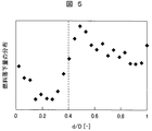
次に、バイオマス燃焼ボイラの火炉1内の燃焼解析より求めた固体燃料の落下量の分布である固体燃料分布図を図5に示す。解析では、最大粒径が7mmの固体粒子を火炉内へ投入した場合を設定して解析を行った。
Next, FIG. 5 shows a solid fuel distribution diagram which is a distribution of the amount of falling solid fuel obtained from the combustion analysis in the
図7の固体燃料分布図に示したように、火炉1の底部のボトムホッパ15の上端から下端までの水平距離をDとすると、固体燃料の分布は火炉1の中央で高く、0.4<d/D<1.0の領域での固体燃料の落下は、固体燃料の全落下量の80%以上となることが数値解析から分かった。
As shown in the solid fuel distribution diagram of FIG. 7, when the horizontal distance from the upper end to the lower end of the
このことから、本実施例のバイオマス燃焼ボイラにおいては、流体噴霧装置12を挿入するために火炉1の壁面に設ける前記開口部13の位置dが、0.4D<d<Dの範囲に設定されるように設置し、火炉1の底部のボトムホッパ15に堆積したバイオマス未燃分16の除去効果を高めたバイオマス燃焼ボイラの運転を実施する。
From this, in the biomass combustion boiler of the present embodiment, the position d of the
流体噴霧装置12はスートブロア14と類似の装置であるため、流体噴霧装置12を用いてバイオマス未燃分16を除去できる範囲は、噴射口18からせいぜい半径3m以内だと推定する。このことから、前記開口部13のボトムホッパ15斜面からの距離aは、0<a<3mに設定することが望ましい。
Since the
以上説明した様に、本実施例によれば、燃料としてバイオマス燃料を燃焼させる場合に、バイオマス燃焼ボイラの火炉のボトムホッパに堆積したバイオマス未燃分を減少させて、ボイラの安全性と燃焼効率を共に向上させたバイオマス燃焼ボイラが実現できる。 As described above, according to this embodiment, when biomass fuel is burned as fuel, the biomass unburned matter accumulated in the bottom hopper of the furnace of the biomass combustion boiler is reduced, and the safety and combustion efficiency of the boiler are reduced. An improved biomass combustion boiler can be realized.
次に 本発明の第2実施例であるバイオマス燃焼ボイラについて図6及び図7を用いて説明する。 Next, the biomass combustion boiler which is 2nd Example of this invention is demonstrated using FIG.6 and FIG.7.
本実施例のバイオマス燃焼ボイラは、図1乃至図3に示した先の実施例のバイオマス燃焼ボイラと基本的な構成は同じであるので、両者に共通した構成の説明は省略し、相違する構成についてのみ説明する。 The biomass combustion boiler of the present embodiment has the same basic configuration as the biomass combustion boiler of the previous embodiment shown in FIGS. Only will be described.
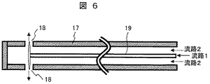
図6は、本実施例であるバイオマス燃焼ボイラに設置された流体噴霧装置12に用いるチューブ17の構造である。本実施例では、噴霧流体装置12の噴霧媒体として油やガスなどの可燃性流体を用いる。チューブ17内の流路は2つに分かれており、可燃性流体はチューブ17の内側の流路(流路1)を流れる。
FIG. 6 shows the structure of the
流路1の外側に位置する流路2には空気を流して、内側の流路1の温度が高くなるのを防いでいる。チューブ17を流れる2種類の流体は、噴射口18から火炉1底部のボトムホッパ15に堆積したバイオマス未燃分16に向けて噴霧される。
Air is passed through the
前記噴霧流体装置12のチューブ17から高温の火炉1内に噴霧された可燃性流体は火炉1内で燃焼し、その燃焼火炎による熱によって火炉1底部のボトムホッパ15に堆積したバイオマス未燃分16を燃焼させる。
The combustible fluid sprayed from the
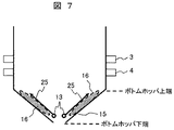
本実施例のバイオマス燃焼ボイラにおいて、噴霧流体装置12のチューブ17から火炉1内に噴霧される好適な流体の噴霧形態を図7に示す。火炉1の火炉壁に形成した開口部13はボトムホッパ15の下端に近い位置に設ける。噴霧流体装置12のチューブ17は、噴射口18をボトムホッパ15の傾斜に対して平行な方向(図5の矢印の方向)に向けた状態で火炉1内に挿入されるが、火炉1内に挿入された後に、噴霧流体装置12のチューブ17は回転させずに、チューブ17の噴射口18の向きを固定したまま前記チューブ17を火炉1内に移動して挿入する。
In the biomass combustion boiler of the present embodiment, FIG. 7 shows a suitable fluid spraying form sprayed from the
噴霧流体装置12のチューブ17に形成した噴射口18から、丁度、図5に矢印25として示したように、火炉1底部のボトムホッパ15に堆積したバイオマス未燃分16に向けて噴霧した可燃性流体によって形成される燃焼火炎は、火炉1の炉壁と接触することなくボトムホッパ15に堆積したバイオマス未燃分16を燃焼させる。
A combustible fluid sprayed from an
以上説明した様に、本実施例によっても、燃料としてバイオマス燃料を燃焼させる場合に、バイオマス燃焼ボイラの火炉のボトムホッパに堆積したバイオマス未燃分を減少させて、ボイラの安全性と燃焼効率を共に向上させたバイオマス燃焼ボイラが実現できる。 As described above, according to the present embodiment, when biomass fuel is burned as fuel, the unburned biomass accumulated in the bottom hopper of the furnace of the biomass combustion boiler is reduced, so that both the safety and the combustion efficiency of the boiler are achieved. An improved biomass combustion boiler can be realized.
本発明は、バイオマス燃料を燃焼させるバイオマス燃焼ボイラ、及び微粉炭とバイオマスを混合燃焼させるバイオマス燃焼ボイラに適用可能である。 The present invention is applicable to a biomass combustion boiler that burns biomass fuel and a biomass combustion boiler that mixes and burns pulverized coal and biomass.
1:火炉、2:後部伝熱面、 3:微粉炭バーナ、4:バイオマスバーナ、5:伝熱管群、7:排ガスダクト、8:石炭バンカ、9 石炭ミル、10:バイオマスバンカ、11:バイオマスミル、12:流体噴霧装置、13:開口部、14:スートブロア、15:ボトムホッパ、16:バイオマス未燃分、17:チューブ、18:噴射口、19:燃料供給管、20:圧力検出器、21:圧力調整弁、22:圧力調整弁制御装置。 1: furnace, 2: rear heat transfer surface, 3: pulverized coal burner, 4: biomass burner, 5: heat transfer tube group, 7: exhaust gas duct, 8: coal bunker, 9 coal mill, 10: biomass bunker, 11: biomass Mill: 12: Fluid spraying device, 13: Opening part, 14: Soot blower, 15: Bottom hopper, 16: Unburned biomass, 17: Tube, 18: Injection port, 19: Fuel supply pipe, 20: Pressure detector, 21 : Pressure regulating valve, 22: Pressure regulating valve control device.
Claims (8)
前記流体噴霧装置には、流体を供給すると共に火炉内に該流体を噴霧するチューブが設置され、前記チューブに流体を火炉内に噴霧する流体の噴射口が形成されており、前記流体噴霧装置は前記開口部から火炉内に前記チューブを挿入できるように移動可能に構成され、更に前記チューブは噴射口の位置と方向を変えられるようにこの挿入方向を中心軸にして回転可能に構成されていることを特徴とするバイオマス燃焼ボイラ。 In the biomass combustion boiler according to claim 1,
The fluid spraying device is provided with a tube for supplying fluid and spraying the fluid in a furnace, and a fluid injection port for spraying the fluid into the furnace is formed in the tube. The tube is configured to be movable so that the tube can be inserted into the furnace from the opening, and the tube is configured to be rotatable about the insertion direction as a central axis so that the position and direction of the injection port can be changed. A biomass-fired boiler characterized by that.
前記流体噴霧装置から噴霧する流体は、蒸気または空気の不燃流体を使用することを特徴とするバイオマス燃焼ボイラ。 In the biomass combustion boiler according to claim 1,
The fluid sprayed from the fluid spraying device uses a non-combustible fluid such as steam or air.
前記流体噴霧装置は、噴霧する流体の圧力を検出する圧力検出器と、噴霧する流体の圧力および流量を調整可能な調整弁と、前記圧力検出器で検出した流体の圧力値に基づいて前記調整弁の開度を調節する制御装置を備えていることを特徴とするバイオマス燃焼ボイラ。 In the biomass combustion boiler according to claim 1,
The fluid spraying device includes a pressure detector that detects a pressure of a fluid to be sprayed, an adjustment valve that can adjust a pressure and a flow rate of the fluid to be sprayed, and the adjustment based on a pressure value of the fluid detected by the pressure detector. A biomass-fired boiler comprising a control device for adjusting the opening of a valve.
ボイラの火炉上部には前記伝熱管の近くに伝熱管表面の付着物を除去するスートブロアが設置されており、前記流体噴霧装置は前記スートブロアが稼動した後で、バイオマス燃焼ボイラの負荷が変化した後に、該流体噴霧装置に備えた流体を噴霧するチューブを開口部から火炉内に挿入して火炉内に流体を噴霧する操作を行うように構成したことを特徴とするバイオマス燃焼ボイラ。 In the biomass combustion boiler according to claim 1,
A soot blower for removing deposits on the surface of the heat transfer tube is installed near the heat transfer tube in the upper part of the furnace of the boiler, and after the soot blower is operated in the fluid spraying device, the load of the biomass combustion boiler is changed. A biomass combustion boiler configured to insert a tube for spraying a fluid provided in the fluid spraying device into the furnace through an opening and spray the fluid into the furnace.
前記流体噴霧装置から噴霧する流体は、燃料となる可燃流体と空気を使用することを特徴とするバイオマス燃焼ボイラ。 In the biomass combustion boiler according to claim 1,
A biomass combustion boiler characterized by using a combustible fluid and air as fuel as the fluid sprayed from the fluid spraying device.
火炉の底部の前記ボトムホッパの上端から下端までの水平距離をD、前記ボトムホッパの上端から前記開口部までの水平距離をdとすると、前記開口部の設置位置を、0.4D<d<Dの範囲となるように設定したことを特徴とするバイオマス燃焼ボイラ。 In the biomass combustion boiler according to claim 1,
When the horizontal distance from the upper end to the lower end of the bottom hopper at the bottom of the furnace is D and the horizontal distance from the upper end of the bottom hopper to the opening is d, the installation position of the opening is 0.4D <d <D. A biomass-fired boiler characterized by being set to be in a range.
火炉の底部の前記ボトムホッパ斜面から前記開口部13までの距離をaとすると、前記開口部の設置位置aを、0<a<3mの範囲に設定したことを特徴とするバイオマス燃焼ボイラ。 In the biomass combustion boiler according to claim 7,
A biomass combustion boiler, wherein the installation position a of the opening is set in a range of 0 <a <3 m, where a is the distance from the bottom hopper slope at the bottom of the furnace to the opening 13.
Priority Applications (1)
| Application Number | Priority Date | Filing Date | Title |
|---|---|---|---|
| JP2011111936A JP5498434B2 (en) | 2011-05-19 | 2011-05-19 | Biomass fired boiler |
Applications Claiming Priority (1)
| Application Number | Priority Date | Filing Date | Title |
|---|---|---|---|
| JP2011111936A JP5498434B2 (en) | 2011-05-19 | 2011-05-19 | Biomass fired boiler |
Publications (2)
| Publication Number | Publication Date |
|---|---|
| JP2012241971A true JP2012241971A (en) | 2012-12-10 |
| JP5498434B2 JP5498434B2 (en) | 2014-05-21 |
Family
ID=47463874
Family Applications (1)
| Application Number | Title | Priority Date | Filing Date |
|---|---|---|---|
| JP2011111936A Active JP5498434B2 (en) | 2011-05-19 | 2011-05-19 | Biomass fired boiler |
Country Status (1)
| Country | Link |
|---|---|
| JP (1) | JP5498434B2 (en) |
Cited By (3)
| Publication number | Priority date | Publication date | Assignee | Title |
|---|---|---|---|---|
| WO2017027349A1 (en) * | 2015-08-07 | 2017-02-16 | Red Valve Company, Inc. | Free flow collar for control valves |
| JP2017078550A (en) * | 2015-10-21 | 2017-04-27 | 株式会社Ihi環境エンジニアリング | Boiler |
| JP7576237B2 (en) | 2021-01-18 | 2024-10-31 | 中国電力株式会社 | Conveyor |
Citations (7)
| Publication number | Priority date | Publication date | Assignee | Title |
|---|---|---|---|---|
| JPS5753593A (en) * | 1980-08-07 | 1982-03-30 | Combustion Eng | Gaseous fuel producing apparatus |
| JPS57157926A (en) * | 1981-03-04 | 1982-09-29 | Combustion Eng | Soot blower structural body |
| JPS61114008A (en) * | 1984-11-07 | 1986-05-31 | Mitsubishi Heavy Ind Ltd | Soot blower device |
| JPS62131106A (en) * | 1985-12-04 | 1987-06-13 | Mitsubishi Heavy Ind Ltd | Burning method of steam generator |
| JPH08145329A (en) * | 1994-11-18 | 1996-06-07 | Chubu Electric Power Co Inc | Clinker removal device |
| JP2007183069A (en) * | 2006-01-10 | 2007-07-19 | Babcock Hitachi Kk | Soot blower device |
| JP2010243122A (en) * | 2009-04-09 | 2010-10-28 | Asahi Kasei Chemicals Corp | Clinker removal device |
-
2011
- 2011-05-19 JP JP2011111936A patent/JP5498434B2/en active Active
Patent Citations (7)
| Publication number | Priority date | Publication date | Assignee | Title |
|---|---|---|---|---|
| JPS5753593A (en) * | 1980-08-07 | 1982-03-30 | Combustion Eng | Gaseous fuel producing apparatus |
| JPS57157926A (en) * | 1981-03-04 | 1982-09-29 | Combustion Eng | Soot blower structural body |
| JPS61114008A (en) * | 1984-11-07 | 1986-05-31 | Mitsubishi Heavy Ind Ltd | Soot blower device |
| JPS62131106A (en) * | 1985-12-04 | 1987-06-13 | Mitsubishi Heavy Ind Ltd | Burning method of steam generator |
| JPH08145329A (en) * | 1994-11-18 | 1996-06-07 | Chubu Electric Power Co Inc | Clinker removal device |
| JP2007183069A (en) * | 2006-01-10 | 2007-07-19 | Babcock Hitachi Kk | Soot blower device |
| JP2010243122A (en) * | 2009-04-09 | 2010-10-28 | Asahi Kasei Chemicals Corp | Clinker removal device |
Cited By (4)
| Publication number | Priority date | Publication date | Assignee | Title |
|---|---|---|---|---|
| WO2017027349A1 (en) * | 2015-08-07 | 2017-02-16 | Red Valve Company, Inc. | Free flow collar for control valves |
| US10773878B2 (en) | 2015-08-07 | 2020-09-15 | Red Valve Company, Inc. | Free flow collar for control valves |
| JP2017078550A (en) * | 2015-10-21 | 2017-04-27 | 株式会社Ihi環境エンジニアリング | Boiler |
| JP7576237B2 (en) | 2021-01-18 | 2024-10-31 | 中国電力株式会社 | Conveyor |
Also Published As
| Publication number | Publication date |
|---|---|
| JP5498434B2 (en) | 2014-05-21 |
Similar Documents
| Publication | Publication Date | Title |
|---|---|---|
| US20110209647A1 (en) | Biomass-to-energy combustion method | |
| AU2015307274A1 (en) | Solid and liquid/gas fueled, fully automated, smokeless combustion hot water/steam boiler adjustable according to coal type | |
| CN101532678A (en) | Brown gas (oxyhydrogen gas) ignition system of coal burning boiler of power plant | |
| CN102913900A (en) | Low-ratio biomass circulating fluidized bed with cooling chamber and pollutant control method thereof | |
| JP2009079835A (en) | Boiler device and method for remodeling boiler device | |
| JP4766562B2 (en) | Wood pellet fired steam boiler | |
| JP4296415B2 (en) | Boiler equipment | |
| JP5498434B2 (en) | Biomass fired boiler | |
| JP4386179B2 (en) | Boiler equipment | |
| CN202253668U (en) | Open type hearth circulating fluid bed waste incineration boiler | |
| CN102818247B (en) | Efficient steam boiler for gasification and combined combustion of pulverized coal | |
| WO2017014299A1 (en) | Biomass power generation system using bamboo as main fuel, and method for combusting bamboo in said biomass power generation system | |
| JP4359768B2 (en) | Boiler equipment | |
| JP6887917B2 (en) | Incinerator plant | |
| KR101032773B1 (en) | Boiler furnace for power plant | |
| JP6246709B2 (en) | Combustion burner and boiler | |
| Bullinger et al. | Coal drying improves performance and reduces emissions | |
| CN111520704B (en) | BFG burner device, operation method thereof and boiler having the same | |
| JP2017146077A (en) | Boiler | |
| CN104390229B (en) | Take the air supply method of the boiler of air zoning | |
| CN204254662U (en) | Take the boiler of air zoning | |
| JP7781151B2 (en) | Combustion equipment, boilers, and combustion methods | |
| JP5881584B2 (en) | boiler | |
| JP6087793B2 (en) | boiler | |
| Shastri | Study of efficiency improvement and optimization in CFB |
Legal Events
| Date | Code | Title | Description |
|---|---|---|---|
| A621 | Written request for application examination |
Free format text: JAPANESE INTERMEDIATE CODE: A621 Effective date: 20130308 |
|
| A977 | Report on retrieval |
Free format text: JAPANESE INTERMEDIATE CODE: A971007 Effective date: 20131212 |
|
| A131 | Notification of reasons for refusal |
Free format text: JAPANESE INTERMEDIATE CODE: A131 Effective date: 20131217 |
|
| A521 | Request for written amendment filed |
Free format text: JAPANESE INTERMEDIATE CODE: A523 Effective date: 20140120 |
|
| TRDD | Decision of grant or rejection written | ||
| A01 | Written decision to grant a patent or to grant a registration (utility model) |
Free format text: JAPANESE INTERMEDIATE CODE: A01 Effective date: 20140225 |
|
| A61 | First payment of annual fees (during grant procedure) |
Free format text: JAPANESE INTERMEDIATE CODE: A61 Effective date: 20140307 |
|
| R150 | Certificate of patent or registration of utility model |
Ref document number: 5498434 Country of ref document: JP Free format text: JAPANESE INTERMEDIATE CODE: R150 |
|
| S111 | Request for change of ownership or part of ownership |
Free format text: JAPANESE INTERMEDIATE CODE: R313111 |
|
| R350 | Written notification of registration of transfer |
Free format text: JAPANESE INTERMEDIATE CODE: R350 |
|
| R250 | Receipt of annual fees |
Free format text: JAPANESE INTERMEDIATE CODE: R250 |
|
| R250 | Receipt of annual fees |
Free format text: JAPANESE INTERMEDIATE CODE: R250 |
|
| R250 | Receipt of annual fees |
Free format text: JAPANESE INTERMEDIATE CODE: R250 |
|
| R250 | Receipt of annual fees |
Free format text: JAPANESE INTERMEDIATE CODE: R250 |
|
| S533 | Written request for registration of change of name |
Free format text: JAPANESE INTERMEDIATE CODE: R313533 |
|
| R350 | Written notification of registration of transfer |
Free format text: JAPANESE INTERMEDIATE CODE: R350 |
|
| R250 | Receipt of annual fees |
Free format text: JAPANESE INTERMEDIATE CODE: R250 |
|
| R250 | Receipt of annual fees |
Free format text: JAPANESE INTERMEDIATE CODE: R250 |
|
| R250 | Receipt of annual fees |
Free format text: JAPANESE INTERMEDIATE CODE: R250 |
|
| R250 | Receipt of annual fees |
Free format text: JAPANESE INTERMEDIATE CODE: R250 |
|
| R250 | Receipt of annual fees |
Free format text: JAPANESE INTERMEDIATE CODE: R250 |
|
| R250 | Receipt of annual fees |
Free format text: JAPANESE INTERMEDIATE CODE: R250 |