JP6463077B2 - Massage machine - Google Patents

Massage machine Download PDF

Info

Publication number
JP6463077B2
JP6463077B2 JP2014217325A JP2014217325A JP6463077B2 JP 6463077 B2 JP6463077 B2 JP 6463077B2 JP 2014217325 A JP2014217325 A JP 2014217325A JP 2014217325 A JP2014217325 A JP 2014217325A JP 6463077 B2 JP6463077 B2 JP 6463077B2
Authority
JP
Japan
Prior art keywords
massage
unit
massage unit
sensor
units
Prior art date
Legal status (The legal status is an assumption and is not a legal conclusion. Google has not performed a legal analysis and makes no representation as to the accuracy of the status listed.)
Active
Application number
JP2014217325A
Other languages
Japanese (ja)
Other versions
JP2016083104A (en
JP2016083104A5 (en
Inventor
知己 長光
知己 長光
啓介 高塚
啓介 高塚
福田 知治
知治 福田
Current Assignee (The listed assignees may be inaccurate. Google has not performed a legal analysis and makes no representation or warranty as to the accuracy of the list.)
Family Inada Co Ltd
Original Assignee
Family Inada Co Ltd
Priority date (The priority date is an assumption and is not a legal conclusion. Google has not performed a legal analysis and makes no representation as to the accuracy of the date listed.)
Filing date
Publication date
Application filed by Family Inada Co Ltd filed Critical Family Inada Co Ltd
Priority to JP2014217325A priority Critical patent/JP6463077B2/en
Priority to CN201910180593.7A priority patent/CN110063879B/en
Priority to CN201580055724.9A priority patent/CN107072868B/en
Priority to PCT/JP2015/068037 priority patent/WO2016063574A1/en
Publication of JP2016083104A publication Critical patent/JP2016083104A/en
Priority to US15/494,281 priority patent/US10966900B2/en
Publication of JP2016083104A5 publication Critical patent/JP2016083104A5/ja
Application granted granted Critical
Publication of JP6463077B2 publication Critical patent/JP6463077B2/en
Active legal-status Critical Current
Anticipated expiration legal-status Critical

Links

Images

Description

本発明はマッサージ機に関する。   The present invention relates to a massage machine.

従来、複数のローラ部及びメカユニットが身長方向に沿って設けられたマッサージ機が知られている。この複数のローラ部及びメカユニットは、独立して背凭れ部から脚載部までを移動可能とされている。そして、マイクロコンピュータの素子が配置された基板により構成される制御部によって、それぞれのローラ部及びメカユニットがお互いに衝突しないよう制御されている(例えば、特許文献1の図9参照)。   Conventionally, a massage machine in which a plurality of roller units and a mechanical unit are provided along the height direction is known. The plurality of roller portions and the mechanical unit are independently movable from the backrest portion to the leg rest portion. Each roller unit and mechanical unit are controlled so as not to collide with each other by a control unit configured by a substrate on which microcomputer elements are arranged (see, for example, FIG. 9 of Patent Document 1).

特開2009−157号公報JP 2009-157 A

上記特許文献1に記載のマッサージ機は、複数のローラ部及びメカユニットが衝突しないよう、予め設定されたプログラムに従って動作するものと考えられる。しかし、マッサージ機は、予め設定されたプログラムに従ってマッサージユニットを動作させて使用する他、使用者が操作器を操作してマッサージユニットを所望する位置(施療部位)に移動させて使用する場合もある。従って、特許文献1のマッサージ機では、複数のローラ部及びメカユニットが適切な相対位置を維持できず、ひいては衝突を回避できない恐れがある。そこで本発明は、上述した問題を解消するためになされたものであり、複数のマッサージユニットが適切な相対位置を維持することができるマッサージ機を提供することを目的とする。   The massage machine described in Patent Literature 1 is considered to operate according to a preset program so that the plurality of roller units and the mechanical unit do not collide. However, the massage machine may be used by operating the massage unit according to a preset program, or by moving the massage unit to a desired position (treatment site) by operating the operation unit. . Therefore, in the massage machine of patent document 1, a some roller part and a mechanical unit cannot maintain an appropriate relative position, and there exists a possibility that a collision cannot be avoided by extension. Then, this invention is made | formed in order to eliminate the problem mentioned above, and it aims at providing the massage machine which a several massage unit can maintain an appropriate relative position.

本発明は、被施療部をマッサージするマッサージユニットが、身長方向に沿って複数設けられたマッサージ機において、前記マッサージユニットとして、相対的に上側に配置される第1マッサージユニットと、相対的に下側に配置される第2マッサージユニットと、前記マッサージユニットの動作を制御する制御手段と、を有し、前記第1及び第2マッサージユニットのうち少なくとも一方のマッサージユニットは、身長方向に昇降可能であり、前記第1マッサージユニットと前記第2マッサージユニットの相対位置を検出するセンサを有し、前記第1及び第2マッサージユニットは、身長方向に独立して昇降可能であり、前記第1及び第2マッサージユニットの身長方向における位置を変更することにより、前記第1又は第2マッサージユニットによって同一の被施療部をマッサージ可能であり、前記センサは、前記相対位置として第1及び第2マッサージユニットの間隔を複数段階検出することができ、前記複数段階は、少なくとも前記第1及び第2マッサージユニットの間隔が所定距離まで近づいた近接状態と、この近接状態よりも若干離反した近接前状態の2段階の状態を有し、前記センサは、前記第1マッサージユニットに対する前記第2マッサージユニットの近接を検出する第1センサ部と、前記第2マッサージユニットに対する前記第1マッサージユニットの近接を検出する第2センサ部と、を有することを特徴とする。
このような構成とすることにより、使用者が所望する位置(施療部位)にマッサージユニットを移動させても、センサが機能することにより、第1マッサージユニットと第2マッサージユニットが所定の相対位置となったことを検出することができる。これにより例えば、第1マッサージユニットと第2マッサージユニットを所定の相対位置として一体的に昇降させたり、マッサージユニットの衝突を適切に回避したりすることができる。
また、このような構成とすることにより、第1マッサージユニットと第2マッサージユニットの相対位置の検出範囲が広がる。
また、第1マッサージユニットと第2マッサージユニットが所定の相対位置となったことを検出する精度が更に高まり、例えば、マッサージユニットの衝突防止の精度が高まる。
The present invention provides a massage machine in which a plurality of massage units for massaging a treatment portion are provided along the height direction, and the first massage unit disposed on the relatively upper side as the massage unit is relatively lower A second massage unit disposed on the side, and a control means for controlling the operation of the massage unit, and at least one of the first and second massage units can be moved up and down in the height direction. A sensor for detecting a relative position between the first massage unit and the second massage unit, wherein the first and second massage units can be moved up and down independently in a height direction; 2 By changing the position of the massage unit in the height direction, the first or second massage unit By Tsu preparative is possible massaging the same the treatment site, the sensor, the interval between the first and second massage unit as the relative position can be a plurality of stages detecting, the plurality of stages includes at least the first and The sensor has two stages of a proximity state in which the interval between the second massage units is close to a predetermined distance and a pre-proximity state that is slightly separated from the proximity state, and the sensor is configured to perform the second massage on the first massage unit. It has a 1st sensor part which detects proximity of a unit, and a 2nd sensor part which detects proximity of the 1st massage unit to the 2nd massage unit.
By adopting such a configuration, even if the massage unit is moved to a position (treatment site) desired by the user, the sensor functions so that the first massage unit and the second massage unit are in a predetermined relative position. Can be detected. Thereby, for example, the first massage unit and the second massage unit can be integrally moved up and down as a predetermined relative position, or the collision of the massage unit can be appropriately avoided.
Moreover, by setting it as such a structure, the detection range of the relative position of a 1st massage unit and a 2nd massage unit spreads.
Moreover, the precision which detects that the 1st massage unit and the 2nd massage unit became the predetermined relative position further increases, for example, the precision of the collision prevention of a massage unit increases.

また、前記センサは、前記第1マッサージユニットの上下位置を検出する第3センサ部と、前記第2マッサージユニットの上下位置を検出する第4センサ部と、を有し、前記制御手段は、前記第3センサ部と前記第4センサ部による検出値の差分値を算出し、前記差分値に基づいて前記相対位置を検出することが好ましい。
このような構成とすることにより、第1マッサージユニットと第2マッサージユニットの相対位置の検出範囲が広がる。
The sensor includes a third sensor unit that detects a vertical position of the first massage unit, and a fourth sensor unit that detects a vertical position of the second massage unit. It is preferable that a difference value between detection values by the third sensor unit and the fourth sensor unit is calculated, and the relative position is detected based on the difference value.
By setting it as such a structure, the detection range of the relative position of a 1st massage unit and a 2nd massage unit spreads.

また、前記制御手段は、前記第1及び第2マッサージユニットが同一方向へ上昇又は下降する際、進行方向前側のマッサージユニットの昇降速度は、進行方向後側のマッサージユニットの昇降速度よりも速くなるように制御することが好ましい。
このような構成とすることにより、マッサージユニットの衝突防止の精度が更に高まる。しかも、両マッサージユニットを近づけた状態としながらスムーズに上昇又は下降させることができる。
In addition, when the first and second massage units are moved up or down in the same direction, the control means is configured such that the lifting speed of the massage unit on the front side in the traveling direction is faster than the lifting speed of the massage unit on the rear side in the traveling direction. It is preferable to control as described above.
By setting it as such a structure, the precision of the collision prevention of a massage unit further increases. In addition, the two massage units can be smoothly raised or lowered while being brought close to each other.

また、前記制御手段は、前記第1及び第2マッサージユニットが同一方向へ上昇又は下降する際、進行方向前側のマッサージユニットが進行方向後側のマッサージユニットよりも先に移動を開始するよう制御することが好ましい。
このような構成とすることにより、マッサージユニットの衝突防止の精度が更に高まる。しかも、両マッサージユニットを近づけた状態としながらスムーズに上昇又は下降させることができる。
In addition, the control unit controls the front massage unit to start moving before the rear massage unit in the traveling direction when the first and second massage units are moved up or down in the same direction. It is preferable.
By setting it as such a structure, the precision of the collision prevention of a massage unit further increases. In addition, the two massage units can be smoothly raised or lowered while being brought close to each other.

また、前記制御手段は、一方のマッサージユニットが他方のマッサージユニットに近づく方向に上昇又は下降している際に両マッサージユニットの間隔が所定距離となったことを検出すると、一方のマッサージユニットの移動を停止する、又は一方のマッサージユニットを他方のマッサージユニットから離反させるよう制御することが好ましい。
このような構成とすることにより、マッサージユニットの衝突を適切に回避することができる。
Further, when the control means detects that the distance between the two massage units is a predetermined distance when one massage unit is rising or descending in a direction approaching the other massage unit, the movement of one massage unit is detected. It is preferable to control so that one massage unit is separated from the other massage unit.
By setting it as such a structure, the collision of a massage unit can be avoided appropriately.

本発明によれば、複数のマッサージユニットが適切な相対位置を維持することができる。   According to the present invention, a plurality of massage units can maintain an appropriate relative position.
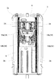
本発明の一実施形態に係るマッサージ機の斜視図である。It is a perspective view of a massage machine concerning one embodiment of the present invention. マッサージ機の機能ブロック図である。It is a functional block diagram of a massage machine. 背凭れ部の正面図である。It is a front view of a backrest part. 第1マッサージユニットの斜視図である。It is a perspective view of a 1st massage unit. 部材の一部を省略した第1マッサージユニットの斜視図である。It is a perspective view of the 1st massage unit which omitted a part of member. 第1マッサージユニットの正面図である。It is a front view of a 1st massage unit. 第1マッサージユニットの側面図であり、第1マッサージ機構が後退した状態を示している。It is a side view of the 1st massage unit, and has shown the state where the 1st massage mechanism moved backward. 第1マッサージユニットの側面図であり、第1マッサージ機構が進出した状態を示している。It is a side view of the 1st massage unit, and has shown the state where the 1st massage mechanism advanced. 揉み軸と叩き軸の正面図である。It is a front view of a kneading shaft and a hitting shaft. 第2マッサージユニットの斜視図である。It is a perspective view of the 2nd massage unit. 部材の一部を省略した第2マッサージユニットの斜視図である。It is a perspective view of the 2nd massage unit which omitted a part of member. 第2マッサージユニットの正面図である。It is a front view of a 2nd massage unit. 第2マッサージユニットの側面であり、第2マッサージ機構が後退した状態を示している。It is the side of the 2nd massage unit, and has shown the state where the 2nd massage mechanism retreated. 第2マッサージユニットの側面であり、第2マッサージ機構が進出した状態を示している。It is the side of the 2nd massage unit, and has shown the state where the 2nd massage mechanism advanced. 第2マッサージユニットのアームの斜視図である。It is a perspective view of the arm of the 2nd massage unit. 揉み動作の説明図である。It is explanatory drawing of stagnation operation | movement. 揉み動作の説明図である。It is explanatory drawing of stagnation operation | movement. 揉み動作の説明図である。It is explanatory drawing of stagnation operation | movement. 揉み動作の説明図である。It is explanatory drawing of stagnation operation | movement. 動作1のフロー図である。FIG. 6 is a flowchart of operation 1. 動作1の説明図である。FIG. 10 is an explanatory diagram of operation 1. 動作2及び動作3のフロー図である。It is a flowchart of the operation | movement 2 and the operation | movement 3. 動作2及び動作3の説明図である。It is explanatory drawing of the operation | movement 2 and the operation | movement 3. FIG. 動作4の説明図である。FIG. 10 is an explanatory diagram of operation 4. 動作5の説明図である。FIG. 10 is an explanatory diagram of operation 5. 動作6の説明図である。FIG. 10 is an explanatory diagram of an operation 6. 動作7の説明図である。FIG. 10 is an explanatory diagram of an operation 7; 動作8の説明図である。FIG. 10 is an explanatory diagram of operation 8. 動作9及び動作10のフロー図である。FIG. 11 is a flowchart of the operation 9 and the operation 10. 他の実施形態に係るマッサージユニットの正面図である。It is a front view of the massage unit concerning other embodiments. 他の実施形態に係るマッサージ機構の正面図である。It is a front view of the massage mechanism which concerns on other embodiment. 他の実施形態に係るリンクの説明図である。It is explanatory drawing of the link which concerns on other embodiment. 他の実施形態に係るセンサの説明図である。It is explanatory drawing of the sensor which concerns on other embodiment.

[全体構成]
以下、本発明のマッサージ機1の全体構成について説明する。図1は本発明の一実施形態に係るマッサージ機1の斜視図である。図2はマッサージ機1の機能ブロック図である。図3は背凭れ部3の正面図である。なお、以下の説明で用いる方向の概念は、図1に示す起立姿勢のマッサージ機1に着座した使用者から見たときの方向の概念と一致するものとし、その他の場合は適宜説明するものとする。
[overall structure]
Hereinafter, the whole structure of the massage machine 1 of this invention is demonstrated. FIG. 1 is a perspective view of a massage machine 1 according to an embodiment of the present invention. FIG. 2 is a functional block diagram of the massage machine 1. FIG. 3 is a front view of the backrest 3. In addition, the concept of the direction used in the following description shall be the same as the concept of the direction when viewed from the user seated on the massage machine 1 in the standing posture shown in FIG. 1, and will be described as appropriate in other cases. To do.

図1に示すとおり、本発明のマッサージ機1は、主として、使用者が着座する座部2と、座部2の後部にリクライニング可能に設けられた使用者が凭れる背凭れ部3と、座部2の前部に上下揺動可能に設けられた使用者の脚部及び足部を支持するフットレスト4と、座部2の左右両側に設けられた使用者が腕部を載置する肘掛け部5と、背凭れ部3の上部に設けられた使用者の頭部を支持する枕部6と、座部2を支持するとともに床面に設置される脚フレーム7と、を有している。そして、背凭れ部3には、使用者の上半身を後方からマッサージする身長方向に沿った複数のマッサージユニット8,9が設けられている。   As shown in FIG. 1, the massage machine 1 of the present invention mainly includes a seat 2 on which a user is seated, a backrest 3 on which a user can recline provided at the rear of the seat 2, and a seat. The footrest 4 that supports the user's legs and feet provided on the front part of the part 2 so as to be able to swing up and down, and the armrest part on which the user is provided on both the left and right sides of the seat part 2 to place the arm part 5, a pillow portion 6 that supports the user's head provided at the upper portion of the backrest portion 3, and a leg frame 7 that supports the seat portion 2 and is installed on the floor surface. And the backrest part 3 is provided with a plurality of massage units 8 and 9 along the height direction for massaging the upper body of the user from behind.

また、背凭れ部3の側部には、上腕又は肩を左右方向から押圧又は保持するエアセル10が設けられている。座部2には、使用者の臀部又は大腿部を下方から押圧するエアセル11と、臀部又は大腿部を左右方向から押圧又は保持するエアセル12と、が設けられている。フットレスト4には、使用者の脚部及び足部を左右方向から押圧又は保持するエアセル13が設けられている。肘掛け部5には、前腕を上下から押圧又は保持するエアセル14が設けられている。これらエアセル10〜14は、座部の下方に設けられたポンプ及びバルブ等からなるエアユニット20(図2参照)からのエアの給排気によって膨張収縮する。   In addition, an air cell 10 that presses or holds the upper arm or the shoulder from the left-right direction is provided on the side portion of the backrest portion 3. The seat 2 is provided with an air cell 11 that presses the user's buttocks or thighs from below and an air cell 12 that presses or holds the buttocks or thighs from the left and right directions. The footrest 4 is provided with an air cell 13 that presses or holds the leg and foot of the user from the left and right directions. The armrest 5 is provided with an air cell 14 that presses or holds the forearm from above and below. These air cells 10 to 14 expand and contract by air supply / exhaust from an air unit 20 (see FIG. 2) including a pump, a valve, and the like provided below the seat.

図1及び図2に示すとおり、背凭れ部3は、座部2の下方に設けられたアクチュエータ21により、座部2に対して前後方向にリクライニング可能に構成されており、図1に示す起立姿勢から背凭れ面が床面と略水平となるリクライニング姿勢までの間の任意の位置で停止できるようになっている。なお、肘掛け部5は、背凭れ部3のリクライニングに連動して後方へ移動し、背凭れ部3の起立に連動して前方へ移動するよう構成されている。フットレスト4は、座部2の下方に設けられたアクチュエータ22により、座部2に対して上下方向に揺動可能に構成されており、図1に示す垂下姿勢から膝を伸ばした状態で脚部及び足部が支持される上昇姿勢までの間の任意の位置で停止できるようになっている。   As shown in FIGS. 1 and 2, the backrest portion 3 is configured to recline in the front-rear direction with respect to the seat portion 2 by an actuator 21 provided below the seat portion 2. It can be stopped at any position between the posture and the reclining posture where the backrest surface is substantially horizontal to the floor surface. The armrest portion 5 is configured to move backward in conjunction with the reclining of the backrest portion 3 and move forward in conjunction with the standing of the backrest portion 3. The footrest 4 is configured to be swingable in the vertical direction with respect to the seat 2 by an actuator 22 provided below the seat 2, and the leg rests with the knee extended from the hanging posture shown in FIG. And it is possible to stop at any position up to the rising posture where the foot is supported.

図2に示すとおり、座部2の下方には、各エアセル10〜14及び後述する進退エアセル15,16にエアを給排気するポンプ及びバルブ等からなるエアユニット20が設けられている。エアユニット20は、各エアセル10〜14及び進退エアセル15,16を任意の膨張量で維持可能に構成することが好ましく、この場合は各エアセル10〜14及び進退エアセル15,16の膨張量を調節することができる。また、このマッサージ機1には、プログラマブルなマイコン等よりなる制御手段23が設けられており、使用者による操作器27からの指示や予め定められたプログラムに従って、マッサージユニット8,9、エアユニット20、及びアクチュエータ21,22の各動作を制御するよう構成されている。   As shown in FIG. 2, below the seat portion 2, an air unit 20 including a pump and a valve for supplying and exhausting air to each of the air cells 10 to 14 and forward and backward air cells 15 and 16 described later is provided. The air unit 20 is preferably configured so that the air cells 10 to 14 and the advance / retreat air cells 15 and 16 can be maintained at an arbitrary expansion amount. In this case, the expansion amounts of the air cells 10 to 14 and the advance / retreat air cells 15 and 16 are adjusted. can do. Further, the massage machine 1 is provided with a control means 23 composed of a programmable microcomputer or the like, and according to an instruction from the operation device 27 by a user or a predetermined program, the massage units 8 and 9 and the air unit 20 are provided. , And each operation of the actuators 21, 22 is configured to be controlled.

この制御手段23は、座部2の下方に設けられマッサージユニット8,9、エアユニット20、及びアクチュエータ21,22の各動作を制御するメイン制御部24と、マッサージユニット8,9に設けられマッサージユニット8,9の昇降を制御するサブ制御部25,26と、を有している。また、制御手段23には、所定のプログラムに従ってマッサージユニット8,9、エアユニット20、及びアクチュエータ21,22のうち少なくともいずれか1つを自動的に動作させる複数のマッサージコースが記憶されている。使用者が所望するマッサージコースを選択すると、設定されたコース時間が経過するまで自動的に各種動作が行われる。   This control means 23 is provided in the massage unit 8 and 9 and the main control part 24 which is provided below the seat part 2 and controls each operation of the massage units 8 and 9, the air unit 20 and the actuators 21 and 22. And sub-control units 25 and 26 for controlling the raising and lowering of the units 8 and 9. The control means 23 stores a plurality of massage courses that automatically operate at least one of the massage units 8 and 9, the air unit 20, and the actuators 21 and 22 according to a predetermined program. When the user selects a desired massage course, various operations are automatically performed until the set course time elapses.

[背凭れ部の構成]
図1及び図3に示すとおり、背凭れ部3は、正面視で門型に形成された樹脂等よりなる背フレーム3aと、背フレーム3aに組み付けられたマッサージユニット8,9の昇降をガイドするガイド機構3bと、背フレーム3aの前面側に配置されるクッション性を有する背パッド3cと、により構成されている。ガイド機構3bは、身長方向に沿って延設されており、上部及び下部がそれぞれ中部より前方に位置するよう湾曲している(図21参照)。また、前側にラックが形成され、後側にレールが形成されている。そして、複数のマッサージユニット8,9が、このガイド機構3bに昇降可能として支持されている。
[Configuration of backrest]
As shown in FIGS. 1 and 3, the
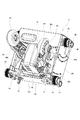
 backrest 3 guides the lifting and lowering of the back frame 3 a made of resin or the like formed in a portal shape in front view and the massage units 8 and 9 assembled to the back frame 3 a. The guide mechanism 3b and a back pad 3c having cushioning properties disposed on the front side of the back frame 3a are configured. The guide mechanism 3b is extended along the height direction, and is curved so that the upper part and the lower part are respectively positioned forward of the middle part (see FIG. 21). A rack is formed on the front side, and a rail is formed on the rear side. A plurality of massage units 8 and 9 are supported by the guide mechanism 3b so as to be movable up and down.

[マッサージユニットの構成]
以下、マッサージユニット8,9の構成について説明する。
図4は第1マッサージユニット8の斜視図である。図5は部材の一部を省略した第1マッサージユニット8の斜視図である。図6は第1マッサージユニット8の正面図である。図7は第1マッサージユニット8の側面図であり、第1マッサージ機構31が後退した状態を示している。図8は第1マッサージユニット8の側面図であり、第1マッサージ機構31が進出した状態を示している。図9は(a)に示す揉み軸41と(b)に示す叩き軸42の正面図である。図10は第2マッサージユニット9の斜視図である。図11は部材の一部を省略した第2マッサージユニット9の斜視図である。図12は第2マッサージユニット9の正面図である。図13は第2マッサージユニット9の側面であり、第2マッサージ機構51が後退した状態を示している。図14は第2マッサージユニット9の側面であり、第2マッサージ機構51が進出した状態を示している。図15は第2マッサージユニット9のアーム60の斜視図である。
[Composition of massage unit]
Hereinafter, the configuration of the massage units 8 and 9 will be described.
FIG. 4 is a perspective view of the first massage unit 8. FIG. 5 is a perspective view of the first massage unit 8 with some members omitted. FIG. 6 is a front view of the first massage unit 8. FIG. 7 is a side view of the first massage unit 8 and shows a state in which the first massage mechanism 31 is retracted. FIG. 8 is a side view of the first massage unit 8 and shows a state where the first massage mechanism 31 has advanced. FIG. 9 is a front view of the kneading shaft 41 shown in (a) and the hitting shaft 42 shown in (b). FIG. 10 is a perspective view of the second massage unit 9. FIG. 11 is a perspective view of the second massage unit 9 with some members omitted. FIG. 12 is a front view of the second massage unit 9. FIG. 13 is a side view of the second massage unit 9 and shows a state in which the second massage mechanism 51 is retracted. FIG. 14 is a side view of the second massage unit 9 and shows a state where the second massage mechanism 51 has advanced. FIG. 15 is a perspective view of the arm 60 of the second massage unit 9.

図3〜図15に示すとおり、マッサージユニット8,9は、身長方向に複数設けられている。本実施形態では、相対的に上側に配置される第1マッサージユニット8と、相対的に下側に配置される第2マッサージユニット9と、が背凭れ部3に設けられている。各マッサージユニット8,9はそれぞれ主として、ガイド機構3bによって昇降可能に支持された本体フレーム30,50と、施療子34,54を有するマッサージ機構31,51と、マッサージ機構31,51を支持する支持フレーム32,52と、マッサージ機構31,51を被施療部に対して進退させる進退駆動部15,16と、本体フレーム30,50と支持フレーム32,52を連結して前後方向に揺動するリンク33,53と、を有して構成されている。   As shown in FIGS. 3 to 15, a plurality of massage units 8 and 9 are provided in the height direction. In the present embodiment, the back massage unit 3 includes a first massage unit 8 disposed on the relatively upper side and a second massage unit 9 disposed on the relatively lower side. The massage units 8 and 9 are mainly supported by the main body frames 30 and 50 supported by the guide mechanism 3b so as to be movable up and down, massage mechanisms 31 and 51 having treatment elements 34 and 54, and support for supporting the massage mechanisms 31 and 51, respectively. Frames 32 and 52, advance / retreat drive parts 15 and 16 for advancing and retreating the massage mechanisms 31 and 51 with respect to the treatment part, and a link that connects the main body frames 30 and 50 and the support frames 32 and 52 and swings in the front-rear direction. 33, 53.

以下、上側の第1マッサージユニット8の構成について詳述する。
図4〜図8に示すとおり、本体フレーム30は、後壁30aと、後壁30aの左右両側から立設された側壁30bと、後壁30aの下部から立設された底壁30cと、後壁30aの上部から立設された上壁30dと、により前方が開口した箱型に構成されている。また、本体フレーム30の内部上方には、第1マッサージユニット8を昇降させるための昇降モータ35と、左右方向に延びる昇降軸36と、昇降モータ35の回転を減速して昇降軸36に伝達する減速器37と、により構成される昇降機構が収容されている。昇降軸36は、両側壁30bに回転可能として支持されている。側壁30bには、上部にガイドローラ38と昇降軸36に取り付けられたピニオン39が設けられ、下部にガイドローラ38とピニオン39が設けられている。ピニオン39とガイドローラ38によりガイド機構3bを挟持しており、昇降モータ35を駆動すると第1マッサージユニット8は身長方向に沿って昇降することができる。第1マッサージユニット8の上部に昇降機構を配置しているため、施療子34を第2マッサージ機構51の施療子54(上施療子54a)に近接させることができる。
Hereinafter, the configuration of the upper first massage unit 8 will be described in detail.
As shown in FIGS. 4 to 8, the main body frame 30 includes a rear wall 30a, side walls 30b erected from the left and right sides of the rear wall 30a, a bottom wall 30c erected from the lower part of the rear wall 30a, The upper wall 30d is erected from the upper part of the wall 30a, and is configured in a box shape whose front is opened. Further, above the inside of the main body frame 30, a lifting motor 35 for lifting and lowering the first massage unit 8, a lifting shaft 36 extending in the left-right direction, and the rotation of the lifting motor 35 are decelerated and transmitted to the lifting shaft 36. The elevating mechanism comprised by the speed reducer 37 is accommodated. The elevating shaft 36 is rotatably supported by the side walls 30b. The side wall 30b is provided with a guide roller 38 and a pinion 39 attached to the elevating shaft 36 in the upper part, and a guide roller 38 and a pinion 39 in the lower part. The guide mechanism 3b is sandwiched between the pinion 39 and the guide roller 38, and when the lifting motor 35 is driven, the first massage unit 8 can be lifted and lowered along the height direction. Since the raising / lowering mechanism is arrange | positioned at the upper part of the 1st massage unit 8, the treatment element 34 can be made to adjoin to the treatment element 54 (upper treatment element 54a) of the 2nd massage mechanism 51. FIG.

第1マッサージ機構31は、先端に施療子34を支持する左右で対をなすアーム40と、アーム40を駆動してマッサージを行わせる駆動機構と、を有している。この駆動機構は、アーム40を支持するとともに対の施療子34を左右方向に近接離反させて揉み動作を行わせる揉み軸41と、対の施療子34を交互に進退させて叩き動作を行わせる叩き軸42と、揉み軸41及び叩き軸42を駆動するマッサージ駆動部としてのマッサージモータ43と、マッサージモータ43の回転を減速して揉み軸41及び叩き軸42に伝達する減速器44と、を有している。そして、駆動機構は箱型のフレーム45によって支持されている。なお、本実施形態では、第1マッサージユニット8の施療子34は、上下方向において単一である。   The first massage mechanism 31 has a pair of left and right arms 40 that support the treatment element 34 at the tip, and a drive mechanism that drives the arms 40 to perform massage. The driving mechanism supports the arm 40 and moves the pair of treatment elements 34 in the left-right direction to move away from each other, and the squeezing shaft 41 and the pair of treatment elements 34 are alternately advanced and retracted to perform a hitting operation. A hitting shaft 42, a massage motor 43 as a massage driving unit that drives the kneading shaft 41 and the hitting shaft 42, and a speed reducer 44 that reduces the rotation of the massage motor 43 and transmits it to the kneading shaft 41 and the hitting shaft 42. Have. The drive mechanism is supported by a box-shaped frame 45. In the present embodiment, the treatment element 34 of the first massage unit 8 is single in the vertical direction.

図9(a)に示すとおり、揉み軸41は、左右方向に延設されており、左右両側にその軸心41bに対して傾斜した傾斜軸41aが設けられている。そして、アーム40がベアリングを介して傾斜軸41aに回動可能として取り付けられている。なお、左右の傾斜軸41aは、互いに平行ではなく正面視で略ハの字となるように傾斜している。また、揉み軸41には、対の施療子34の間隔を検出する幅センサ46が設けられている。図9(b)に示すとおり、叩き軸42は、左右方向に延設されており、左右両側にその軸心42bに対して偏心した偏心軸42aが設けられている。また、図5に示すとおり、叩き軸42とアーム40の後部を連結する連結部材47が、ベアリングを介して偏心軸42aに回動可能として設けられている。なお、左右の偏心軸42aは、叩き軸42の軸心42b回りの位相が互いに異なっている。   As shown in FIG. 9A, the kneading shaft 41 is extended in the left-right direction, and inclined shafts 41a inclined with respect to the axis 41b are provided on both the left and right sides. The arm 40 is attached to the inclined shaft 41a via a bearing so as to be rotatable. The left and right inclined shafts 41a are not parallel to each other but are inclined so as to have a substantially square shape when viewed from the front. In addition, a width sensor 46 that detects the distance between the pair of treatment elements 34 is provided on the massage shaft 41. As shown in FIG. 9B, the hitting shaft 42 extends in the left-right direction, and eccentric shafts 42a that are eccentric with respect to the shaft center 42b are provided on the left and right sides. Further, as shown in FIG. 5, a connecting member 47 that connects the hitting shaft 42 and the rear portion of the arm 40 is provided on the eccentric shaft 42a via a bearing so as to be rotatable. The left and right eccentric shafts 42a have different phases around the shaft center 42b of the hitting shaft 42.

揉み軸41が回転すると、アーム40は連結部材47によって揉み軸41回りの回転が規制されながら三次元的に回動する。すなわち図16に示すように、揉み軸41を一方向に連続的に回転させると、施療子34としては少なくとも左右及び上下方向成分を有するループ状の軌跡を描いて動作し、左右対の施療子34としては左右方向へ動作して近接離反する。このようにして揉み動作が行われる。一方、叩き軸42が回転すると連結部材47の上下運動により、対のアーム40は揉み軸41を支点として交互に進退する。このようにして叩き動作が行われる。なお、本実施形態では、叩き軸42にクラッチを設け、単一のマッサージモータ43を正反転させることで、揉み動作/揉み叩き動作を切り換え可能としているが、個別にマッサージモータ43を設けて揉み動作と叩き動作を独立して行えるようにしてもよい。   When the rubbing shaft 41 rotates, the arm 40 rotates three-dimensionally while the rotation around the rubbing shaft 41 is restricted by the connecting member 47. That is, as shown in FIG. 16, when the kneading shaft 41 is continuously rotated in one direction, the treatment element 34 operates by drawing a loop-like locus having at least left and right and vertical components, and a pair of left and right treatment elements As 34, it moves in the left-right direction and moves away. In this way, the stagnation operation is performed. On the other hand, when the hitting shaft 42 rotates, the pair of arms 40 alternately advance and retract with the rubbing shaft 41 as a fulcrum by the vertical movement of the connecting member 47. In this way, the hitting operation is performed. In the present embodiment, a clutch is provided on the hitting shaft 42 and the single massage motor 43 is reversed in the normal direction so that switching between the kneading operation / the kneading operation can be performed. The operation and the hitting operation may be performed independently.

支持フレーム32は、前後方向に板面を有しており、前面側にフレーム45が固定されることにより第1マッサージ機構31を支持している。本体フレーム30と支持フレーム32の間には、エアユニット20からのエアの給排気により膨張収縮して、第1マッサージ機構31を被施療部に対して進退させる進退駆動部としての進退エアセル15が設けられている。また、支持フレーム32の側方には、本体フレーム30と支持フレーム32を連結して前後方向に揺動するリンク33が設けられている。リンク33を支持フレーム32の側方に配置した理由は、支持フレーム32の後方に配置する場合に比べてマッサージユニット8の前後方向の厚みを抑えることができるからである。このリンク33は前後方向に並設され、相対的に後側に配置された第1リンク部33aと、相対的に前側に配置された第2リンク部33bと、を有している。すなわち、リンク33は四節リンク機構を構成している。   The support frame 32 has a plate surface in the front-rear direction, and supports the first massage mechanism 31 by fixing the frame 45 to the front side. Between the main body frame 30 and the support frame 32, there is an advancing / retreating air cell 15 as an advancing / retreating drive unit that expands / contracts by supply / exhaust of air from the air unit 20 and advances / retreats the first massage mechanism 31 with respect to the treatment portion. Is provided. A link 33 that connects the main body frame 30 and the support frame 32 and swings in the front-rear direction is provided on the side of the support frame 32. The reason why the link 33 is arranged on the side of the support frame 32 is that the thickness in the front-rear direction of the massage unit 8 can be suppressed as compared with the case where the link 33 is arranged behind the support frame 32. The link 33 is provided in parallel in the front-rear direction, and includes a first link portion 33a disposed relatively on the rear side and a second link portion 33b disposed relatively on the front side. That is, the link 33 constitutes a four-bar linkage mechanism.

図7及び図8に示すとおり、第1リンク部33aと第2リンク部33bの長さは異なっており、具体的には、第1リンク部33aの長さが第2リンク部33bの長さよりも短くなるように設定されている。第1リンク部33aは、昇降軸36の近傍においてその上部が揺動軸A1を介して本体フレーム30の側壁30bに枢支され、その下部が枢軸A2を介して支持フレーム32の上部に枢支されている。第2リンク部33bは、昇降軸36の近傍においてその上部が揺動軸A3を介して本体フレーム30の側壁30bに枢支され、その下部が枢軸A4を介して支持フレーム32の下部に枢支されている。なお、第1リンク部33aの揺動軸A1は、第2リンク部33bの揺動軸A3よりも若干後方に位置している。そして、第1リンク部33a及び第2リンク部33bはそれぞれ、側壁30bに設けられた下に凸の円弧状のガイド部30e,30f(図4参照)に枢軸A2,A4が嵌合することにより、その動作がガイドされる。また、図7及び図8に示すとおり、第1リンク部33aと第2リンク部33bを、本体フレーム30との連結部において連結して補強する補強部48が設けられている。このように、負荷のかかるリンク33の揺動軸A1,A3近傍を昇降軸36及び補強部48によって補強することができる。   As shown in FIGS. 7 and 8, the lengths of the first link portion 33a and the second link portion 33b are different. Specifically, the length of the first link portion 33a is greater than the length of the second link portion 33b. Is also set to be shorter. The upper portion of the first link portion 33a is pivotally supported on the side wall 30b of the main body frame 30 via the swing shaft A1 and the lower portion thereof is pivotally supported on the upper portion of the support frame 32 via the pivot axis A2. Has been. The upper portion of the second link portion 33b is pivotally supported on the side wall 30b of the main body frame 30 via the swing shaft A3 and the lower portion thereof is pivotally supported on the lower portion of the support frame 32 via the pivot shaft A4. Has been. Note that the swing axis A1 of the first link portion 33a is located slightly behind the swing axis A3 of the second link portion 33b. The first link portion 33a and the second link portion 33b are respectively formed by fitting the pivots A2 and A4 to the downwardly convex guide portions 30e and 30f (see FIG. 4) provided on the side wall 30b. The operation is guided. Further, as shown in FIGS. 7 and 8, a reinforcing portion 48 that connects and reinforces the first link portion 33 a and the second link portion 33 b at the connecting portion with the main body frame 30 is provided. As described above, the vicinity of the swing axes A1 and A3 of the link 33 to which the load is applied can be reinforced by the elevating shaft 36 and the reinforcing portion 48.

リンク33は、第1マッサージ機構31が最も後退した状態において、本体フレーム30との連結部が支持フレーム32との連結部よりも前方に位置している。すなわち、第1リンク部33aは揺動軸A1が枢軸A2よりも前方に位置し、かつ第2リンク部33bは揺動軸A3が枢軸A4よりも前方に位置している。従って、進退エアセル15が膨張すると、リンク33が下に凸の円弧状の軌跡を描いて揺動するため、第1マッサージ機構31を被施療部に対向する方向と平行に近い軌跡で進退させることができる。また、四節リンク機構を採用しているため、第1マッサージ機構31が最も後退した状態から進退エアセル15が膨張すると、第1リンク部33aが揺動軸A1を中心として前方へ揺動する。しかし、第1リンク部33aよりも長い第2リンク部33bによって、第1リンク部33aの枢軸A2よりも前方かつ下方で支持フレーム32が枢支されているため、第1マッサージ機構31の揺動を抑制し、より被施療部に対向する方向と平行に近い軌跡で進退させることができる。   In the state where the first massage mechanism 31 is most retracted, the link 33 has a connecting portion with the main body frame 30 positioned in front of a connecting portion with the support frame 32. That is, in the first link portion 33a, the swing axis A1 is positioned in front of the pivot A2, and in the second link portion 33b, the swing axis A3 is positioned in front of the pivot A4. Accordingly, when the advancing / retreating air cell 15 expands, the link 33 swings in a downward convex arcuate locus, so that the first massage mechanism 31 is advanced and retracted along a locus that is nearly parallel to the direction facing the treatment portion. Can do. In addition, since the four-bar linkage mechanism is employed, when the advance / retreat air cell 15 expands from the state in which the first massage mechanism 31 is most retracted, the first link portion 33a swings forward about the swing axis A1. However, since the support frame 32 is pivotally supported forward and below the pivot A2 of the first link portion 33a by the second link portion 33b that is longer than the first link portion 33a, the swinging of the first massage mechanism 31 is performed. And can be advanced and retracted along a locus closer to the direction parallel to the treatment portion.

また、第1リンク部33aと第2リンク部33bの長さが異なっているため、第1リンク部33aと第2リンク部33bを前後方向に近接させて設けても第1マッサージ機構31の十分な進出量を確保することができ、第1マッサージユニット8の前後方向の厚みを抑えることができる。また、後側に配置される第1リンク33aの長さが相対的に短いため、第1マッサージ機構31が最も後退した状態を起点として、進出開始直後から十分な前後方向成分の移動量を得ることができる。また、第1マッサージ機構31を進出させる過程で、第1リンク部33aが第2リンク部33bに後方から当接することにより、所定の前後位置で第1マッサージ機構31の進出が制限される。すなわち、第2リンク部33bがストッパとして機能するため、別途ストッパを設ける必要がなく、部品点数を削減できる。   In addition, since the lengths of the first link portion 33a and the second link portion 33b are different, even if the first link portion 33a and the second link portion 33b are provided close to each other in the front-rear direction, the first massage mechanism 31 is sufficient. A sufficient amount of advance can be ensured, and the thickness of the first massage unit 8 in the front-rear direction can be suppressed. Moreover, since the length of the 1st link 33a arrange | positioned at a rear side is relatively short, the movement amount of the front-back direction component sufficient from immediately after advancement is obtained from the state which the 1st massage mechanism 31 retracted most. be able to. Further, in the process of advancing the first massage mechanism 31, the first link part 33a abuts against the second link part 33b from the rear, so that the advancement of the first massage mechanism 31 is restricted at a predetermined front-rear position. That is, since the second link portion 33b functions as a stopper, it is not necessary to provide a separate stopper, and the number of parts can be reduced.

以下、下側の第2マッサージユニット9の構成について詳述する。
図9〜図15に示すとおり、本体フレーム50は、後壁50aと、後壁50aの左右両側から立設された側壁50bと、後壁50aの下部から立設された底壁50cと、後壁50aの上部から立設された上壁50dと、により前方が開口した箱型に構成されている。また、本体フレーム50の内部下方には、第2マッサージユニット9を昇降させるための昇降モータ55と、左右方向に延びる昇降軸56と、昇降モータ55の回転を減速して昇降軸56に伝達する減速器57と、により構成される昇降機構が収容されている。昇降軸56は、両側壁5bに回転可能として支持されている。側壁5bには、部にガイドローラ58と昇降軸56に取り付けられたピニオン59が設けられ、部にガイドローラ58とピニオン59が設けられている。ピニオン59とガイドローラ58によりガイド機構3bを挟持しており、昇降モータ55を駆動すると第2マッサージユニット9は身長方向に沿って昇降することができる。第2マッサージユニット9の下部に昇降機構を配置しているため、施療子54(上施療子54a)を第1マッサージ機構31の施療子34に近接させることができる。
Hereinafter, the configuration of the lower second massage unit 9 will be described in detail.
As shown in FIGS. 9 to 15, the main body frame 50 includes a rear wall 50 a, a side wall 50 b erected from the left and right sides of the rear wall 50 a, a bottom wall 50 c erected from the lower part of the rear wall 50 a, The upper wall 50d is erected from the upper part of the wall 50a, and is configured in a box shape whose front is opened. Further, below the inside of the main body frame 50, an elevating motor 55 for elevating the second massage unit 9, an elevating shaft 56 extending in the left-right direction, and the rotation of the elevating motor 55 are decelerated and transmitted to the elevating shaft 56. An elevating mechanism constituted by the speed reducer 57 is accommodated. Elevating shaft 56 is supported as rotatable side walls 5 0 b. The side wall 5 0 b, a pinion 59 attached to the lifting shaft 56 and the guide roller 58 to the lower portion is provided, the guide roller 58 and the pinion 59 is provided in the upper portion. The guide mechanism 3b is sandwiched between the pinion 59 and the guide roller 58, and when the lifting motor 55 is driven, the second massage unit 9 can be lifted and lowered along the height direction. Since the raising / lowering mechanism is arrange | positioned under the 2nd massage unit 9, the treatment element 54 (upper treatment element 54a) can be made to adjoin to the treatment element 34 of the 1st massage mechanism 31. FIG.

第2マッサージ機構51は、先端に施療子54を支持する左右で対をなすアーム60と、アーム60を駆動してマッサージを行わせる駆動機構と、を有している。この駆動機構は、アーム60を支持するとともに対の施療子54を左右方向に近接離反させて揉み動作を行わせる揉み軸61と、揉み軸61を駆動するマッサージ駆動部としてのマッサージモータ63と、マッサージモータ63の回転を減速して揉み軸61に伝達する減速器64と、を有している。そして、駆動機構は箱型のフレーム65によって支持されている。なお、アーム60は側面視でくの字型に形成されており、その上端に相対的に大径の上施療子54aが設けられ、その下端に相対的に小径の下施療子54bが設けられている。すなわち、第1マッサージユニット8とは異なり、施療子54は上下方向において2つ設けられている。   The 2nd massage mechanism 51 has the arm 60 which makes the right and left which supports the treatment element 54 at the front-end | tip, and the drive mechanism which drives the arm 60 and performs a massage. This drive mechanism includes a massaging shaft 61 that supports the arm 60 and moves the pair of treatment elements 54 close to and away from each other in the left-right direction to perform a massaging operation; a massage motor 63 as a massage driving unit that drives the massaging shaft 61; And a speed reducer 64 that decelerates the rotation of the massage motor 63 and transmits it to the kneading shaft 61. The drive mechanism is supported by a box-shaped frame 65. The arm 60 is formed in a dogleg shape in a side view, and a relatively large-diameter upper treatment element 54a is provided at the upper end thereof, and a relatively small-diameter lower treatment element 54b is provided at the lower end thereof. ing. That is, unlike the first massage unit 8, two treatment elements 54 are provided in the vertical direction.

図9(a)に示すとおり、揉み軸61は、第1マッサージ機構31の揉み軸41と同一の構成であり、左右方向に延設されており、左右両側にその軸心61bに対して傾斜した傾斜軸61aが設けられている。そして、アーム60がベアリングを介して傾斜軸61aに回動可能として取り付けられている。なお、左右の傾斜軸61aは、互いに平行ではなく正面視で略ハの字となるように傾斜している。図15に示すとおり、アーム60の後方には、アーム60と支持フレーム52を連結すべく後端にボールジョイントを有する連結部材67が設けられている。支持フレーム52の前面側には左右方向に沿った溝69が設けられており、連結部材67のボールジョイントが溝69に嵌合している。また、揉み軸61には、対の施療子54の間隔を検出する幅センサ66が設けられている。   As shown in FIG. 9A, the kneading shaft 61 has the same configuration as the kneading shaft 41 of the first massaging mechanism 31, extends in the left-right direction, and is inclined with respect to the axis 61b on both the left and right sides. An inclined shaft 61a is provided. The arm 60 is attached to the inclined shaft 61a via a bearing so as to be rotatable. Note that the left and right inclined shafts 61a are not parallel to each other but are inclined so as to be substantially square-shaped when viewed from the front. As shown in FIG. 15, a connecting member 67 having a ball joint at the rear end is provided behind the arm 60 to connect the arm 60 and the support frame 52. A groove 69 extending in the left-right direction is provided on the front side of the support frame 52, and a ball joint of the connecting member 67 is fitted in the groove 69. Further, a width sensor 66 for detecting the distance between the pair of treatment elements 54 is provided on the massage shaft 61.

揉み軸61が回転すると、アーム60は連結部材67によって揉み軸61回りの回転が規制されながら三次元的に回動する。すなわち図16に示すように、揉み軸61を一方向に連続的に回転させると、施療子54としては少なくとも左右及び上下方向成分を有するループ状の軌跡を描いて動作する。また、左右対の施療子54としては左右方向へ動作して、上施療子54aが近接するときには下施療子54bは離反し、上施療子54aが離反するときには下施療子54bは近接する。このようにして揉み動作が行われる。なお、本実施形態では、第2マッサージ機構51は揉み動作のみ行う構成としたが、第1マッサージ機構31と同様、叩き動作も行うことができる構成としてもよい。   When the rubbing shaft 61 rotates, the arm 60 rotates three-dimensionally while the rotation around the rubbing shaft 61 is restricted by the connecting member 67. That is, as shown in FIG. 16, when the kneading shaft 61 is continuously rotated in one direction, the treatment element 54 operates by drawing a loop-shaped locus having at least left and right and vertical components. The pair of left and right treatment elements 54 operate in the left-right direction. When the upper treatment element 54a comes close, the lower treatment element 54b moves away. When the upper treatment element 54a moves away, the lower treatment element 54b comes closer. In this way, the stagnation operation is performed. In the present embodiment, the second massage mechanism 51 is configured to perform only the kneading operation. However, similarly to the first massage mechanism 31, the second massage mechanism 51 may be configured to perform the tapping operation.

支持フレーム52は、前後方向に板面を有しており、前面側にフレーム65が固定されることにより第2マッサージ機構51を支持している。本体フレーム50と支持フレーム52の間には、エアユニット20からのエアの給排気により膨張収縮して、第2マッサージ機構51を被施療部に対して進退させる進退駆動部としての進退エアセル16が設けられている。また、支持フレーム52の側方には、本体フレーム50と支持フレーム52を連結して前後方向に揺動するリンク53が設けられている。このリンク53は前後方向に並設され、相対的に後側に配置された第1リンク部53aと、相対的に前側に配置された第2リンク部53bと、を有している。すなわち、リンクは四節リンク機構を構成している。   The support frame 52 has a plate surface in the front-rear direction, and supports the second massage mechanism 51 by fixing the frame 65 to the front side. Between the main body frame 50 and the support frame 52, the advancing / retreating air cell 16 as an advancing / retreating drive unit that expands / contracts by supply / exhaust of air from the air unit 20 and advances / retreats the second massage mechanism 51 with respect to the treatment portion. Is provided. A link 53 that connects the main body frame 50 and the support frame 52 and swings in the front-rear direction is provided on the side of the support frame 52. The link 53 is provided side by side in the front-rear direction, and includes a first link portion 53a that is disposed relatively on the rear side and a second link portion 53b that is disposed relatively on the front side. That is, the link constitutes a four-bar linkage mechanism.

第1リンク部53aと第2リンク部53bの長さは異なっており、具体的には、第1リンク部53aの長さが第2リンク部53bの長さよりも短くなるように設定されている。第1リンク部53aは、昇降軸56の近傍においてその下部が揺動軸A5を介して本体フレーム60の側壁60bに枢支され、その上部が枢軸A6を介して支持フレーム52の下部に枢支されている。第2リンク部53bは、昇降軸56の近傍においてその下部が揺動軸A7を介して本体フレーム60の側壁60bに枢支され、その上部が枢軸A8を介して支持フレーム52の上部に枢支されている。なお、第1リンク部53aの揺動軸A5は、第2リンク部53bの揺動軸A7よりも若干後方に位置している。そして、第1リンク部53a及び第2リンク部53bはそれぞれ、側壁50bに設けられた上に凸の円弧状のガイド部50e,50f(図10参照)に枢軸A6,A8が嵌合することにより、その動作がガイドされる。また、図13及び図14に示すとおり、第1リンク部53aと第2リンク部53bを、本体フレーム60との連結部において連結して補強する補強部68が設けられている。このように、負荷のかかるリンク53の揺動軸A5,A7近傍を昇降軸56及び補強部68によって補強することができる。   The lengths of the first link portion 53a and the second link portion 53b are different, and specifically, the length of the first link portion 53a is set to be shorter than the length of the second link portion 53b. . The lower portion of the first link portion 53a is pivotally supported on the side wall 60b of the main body frame 60 via the swing shaft A5 and the upper portion thereof is pivotally supported on the lower portion of the support frame 52 via the pivot A6. Has been. The lower portion of the second link portion 53b is pivotally supported on the side wall 60b of the main body frame 60 via the swing shaft A7 in the vicinity of the elevating shaft 56, and the upper portion thereof is pivotally supported on the upper portion of the support frame 52 via the pivot A8. Has been. The swing axis A5 of the first link portion 53a is located slightly behind the swing axis A7 of the second link portion 53b. The first link portion 53a and the second link portion 53b are respectively formed by fitting the pivots A6 and A8 to the convex arcuate guide portions 50e and 50f (see FIG. 10) provided on the side wall 50b. The operation is guided. Further, as shown in FIGS. 13 and 14, a reinforcing portion 68 is provided to connect and reinforce the first link portion 53 a and the second link portion 53 b at the connecting portion with the main body frame 60. In this way, the vicinity of the swing axes A5 and A7 of the link 53 to which the load is applied can be reinforced by the elevating shaft 56 and the reinforcing portion 68.

リンク53は、第2マッサージ機構51が最も後退した状態において、本体フレーム60との連結部が支持フレーム62との連結部よりも前方に位置している。すなわち、第1リンク部53aは揺動軸A5が枢軸A6よりも前方に位置し、かつ第2リンク部53bは揺動軸A7が枢軸A8よりも前方に位置している。従って、進退エアセル16が膨張すると、リンク53が上に凸の円弧状の軌跡を描いて揺動するため、第2マッサージ機構51を被施療部に対向する方向と平行に近い軌跡で進退させることができる。また、四節リンク機構を採用しているため、第2マッサージ機構51が最も後退した状態から進退エアセル16が膨張すると、第1リンク部53aが揺動軸A5を中心として前方へ揺動する。しかし、第1リンク部53aよりも長い第2リンク部53bによって、第1リンク部53aの枢軸A6よりも前方かつ上方で支持フレーム52が枢支されているため、第2マッサージ機構51の揺動を抑制し、より被施療部に対向する方向と平行に近い軌跡で進退させることができる。   In the link 53, the connecting portion with the main body frame 60 is positioned forward of the connecting portion with the support frame 62 in the state where the second massage mechanism 51 is most retracted. That is, in the first link portion 53a, the swing axis A5 is positioned in front of the pivot A6, and in the second link portion 53b, the swing shaft A7 is positioned in front of the pivot A8. Therefore, when the advancing / retreating air cell 16 expands, the link 53 swings while drawing an upward convex arcuate trajectory, so that the second massage mechanism 51 is advanced and retracted along a trajectory that is nearly parallel to the direction facing the treatment portion. Can do. In addition, since the four-bar linkage mechanism is employed, when the advancing / retreating air cell 16 expands from the state in which the second massage mechanism 51 is most retracted, the first link portion 53a swings forward about the swing axis A5. However, since the support frame 52 is pivotally supported forward and above the pivot A6 of the first link portion 53a by the second link portion 53b that is longer than the first link portion 53a, the second massage mechanism 51 swings. And can be advanced and retracted along a locus closer to the direction parallel to the treatment portion.

また、第1リンク部53aと第2リンク部53bの長さが異なっているため、第1リンク部53aと第2リンク部53bを前後方向に近接させて設けても第2マッサージ機構51の十分な進出量を確保することができ、第2マッサージユニット9の前後方向の厚みを抑えることができる。また、後側に配置される第1リンク53aの長さが相対的に短いため、第2マッサージ機構51が最も後退した状態を起点として、進出開始直後から十分な前後方向成分の移動量を得ることができる。また、第2マッサージ機構51を進出させる過程で、第1リンク部53aが第2リンク部53bに後方から当接することにより、所定の前後位置で第2マッサージ機構51の進出が制限される。すなわち、第2リンク部53bがストッパとして機能するため、別途ストッパを設ける必要がなく、部品点数を削減できる。   In addition, since the lengths of the first link portion 53a and the second link portion 53b are different, even if the first link portion 53a and the second link portion 53b are provided close to each other in the front-rear direction, the second massage mechanism 51 is sufficient. A sufficient amount of advancement can be ensured, and the thickness of the second massage unit 9 in the front-rear direction can be suppressed. Moreover, since the length of the 1st link 53a arrange | positioned at the rear side is relatively short, the movement amount of the front-back direction component sufficient from immediately after advancement is obtained from the state which the 2nd massage mechanism 51 retracted most. be able to. Further, in the process of advancing the second massage mechanism 51, the advancement of the second massage mechanism 51 is restricted at a predetermined front-rear position by the first link portion 53a coming into contact with the second link portion 53b from the rear. That is, since the second link portion 53b functions as a stopper, it is not necessary to provide a separate stopper, and the number of parts can be reduced.

[センサの構成]
図2に示すとおり、マッサージ機1は、第1マッサージユニット8と第2マッサージユニット9の相対位置を検出するセンサ70を有している。以下、このセンサ70について詳述する。
[Sensor configuration]
As shown in FIG. 2, the massage machine 1 includes a sensor 70 that detects a relative position between the first massage unit 8 and the second massage unit 9. Hereinafter, the sensor 70 will be described in detail.

図4に示すとおり、第1マッサージユニット8の下部である底壁30cには、左右方向一方側に磁石を取り付けたマグネットホルダ73が設けられ、左右方向他方側に磁石の近接を検出する第1センサ部71及び第1センサ部71に電気的に接続されたサブ制御部25(図2参照)が設けられている。一方、図10に示すとおり、第2マッサージユニット9の上部である上壁50dには、左右方向一方側に磁石の近接を検出する第2センサ部72及び第2センサ部72に電気的に接続されたサブ制御部26(図2参照)が設けられており、左右方向他方側に磁石を取り付けたマグネットホルダ74が設けられている。サブ制御部25,26は、それぞれ昇降モータ35,55に電気的に接続されており、各マッサージユニット8,9の昇降を制御することができる。また、メイン制御部24にも電気的に接続されている。   As shown in FIG. 4, the bottom wall 30 c, which is the lower part of the first massage unit 8, is provided with a magnet holder 73 with a magnet attached to one side in the left-right direction. A sub control unit 25 (see FIG. 2) electrically connected to the sensor unit 71 and the first sensor unit 71 is provided. On the other hand, as shown in FIG. 10, the upper wall 50d that is the upper portion of the second massage unit 9 is electrically connected to the second sensor unit 72 and the second sensor unit 72 that detect the proximity of the magnet on one side in the left-right direction. The sub-control unit 26 (see FIG. 2) is provided, and a magnet holder 74 with a magnet attached to the other side in the left-right direction is provided. The sub-control units 25 and 26 are electrically connected to the lifting motors 35 and 55, respectively, and can control the lifting and lowering of the massage units 8 and 9. Further, it is also electrically connected to the main control unit 24.

第1センサ部71は、第2マッサージユニット9に設けられたマグネットホルダ74と上下方向に直交する位置が略一致しており、第1マッサージユニット8に対する第2マッサージユニット9の近接を検出することができる。一方、第2センサ部72は、第1マッサージユニット8に設けられたマグネットホルダ73と上下方向に直交する位置が略一致しており、第2マッサージユニット9に対する第1マッサージユニット8の近接を検出することができる。すなわち、センサ70は、第1センサ部71及び第2センサ部72により構成された非接触式のセンサである。上述したように、それぞれのマッサージユニット8,9が相手側のマッサージユニット9,8の近接を検出して、それぞれのサブ制御部25,26が昇降モータ33,55を制御するため、衝突防止の精度が高まる。
The first sensor unit 71 is positioned perpendicular to the magnet holder 74 provided in the second massage unit 9 in the vertical direction is substantially coincident, detects the proximity of the second Ma Tsu surge unit 9 to the first massage unit 8 can do. The second sensor unit 72 is positioned perpendicular to the magnet holder 73 provided in the first massage unit 8 in the vertical direction is substantially coincident, close the first Ma Tsu surge unit 8 with respect to the second massage unit 9 Can be detected. That is, the sensor 70 is a non-contact sensor configured by the first sensor unit 71 and the second sensor unit 72. As described above, each massage unit 8, 9 detects the proximity of the other massage unit 9, 8 and each sub-control unit 25, 26 controls the lifting motors 33, 55. Increases accuracy.

なお、センサ70は、第1マッサージユニット8と第2マッサージユニット9の相対位置として、両マッサージユニット8,9の間隔を複数段階検出することができることが好ましい。例えば、両マッサージユニット8,9の間隔が所定距離まで近づいた「近接状態」とこの近接状態よりも若干離反した「近接前状態」の2段階の状態を検出できるようにすればよい。従って、第1マッサージユニット8と第2マッサージユニット9の相対位置の検出範囲が広がる。また、両マッサージユニット8,9を所定の相対位置(例えば、近接状態又は近接前状態)として、この相対位置を維持した状態で一体的に昇降させることもできる。   In addition, it is preferable that the sensor 70 can detect the space | interval of both the massage units 8 and 9 in multiple steps as a relative position of the 1st massage unit 8 and the 2nd massage unit 9. For example, it is only necessary to be able to detect two stages of a “proximity state” in which the distance between the massage units 8 and 9 is close to a predetermined distance and a “pre-proximity state” slightly separated from the proximity state. Therefore, the detection range of the relative position of the first massage unit 8 and the second massage unit 9 is expanded. Further, both massage units 8 and 9 can be moved up and down integrally with a predetermined relative position (for example, a proximity state or a pre-proximity state) while maintaining the relative position.

図2に示すとおり、背凭れ部3には、第1マッサージユニット8の昇降範囲の上限位置を検出する上限センサ75と、第2マッサージユニット9の昇降範囲の下限位置を検出する下限センサ76と、が設けられており、第1及び第2マッサージユニット8,9は背凭れ部3から離脱しないようになっている。また、第1及び第2マッサージユニット8,9はそれぞれ、昇降軸36,56の回転数を検出することにより上下位置を検出する昇降センサ77,78を有している。第1マッサージユニット8は、上限位置から昇降軸36が何回転したかを昇降センサ77が検出することにより、その上下位置が検出される。第2マッサージユニット9は、下限位置から昇降軸56が何回転したかを昇降センサ78が検出することにより、その上下位置が検出される。   As shown in FIG. 2, the backrest 3 includes an upper limit sensor 75 that detects an upper limit position of the lifting range of the first massage unit 8, and a lower limit sensor 76 that detects a lower limit position of the lifting range of the second massage unit 9. Are provided so that the first and second massage units 8 and 9 are not separated from the backrest 3. Moreover, the 1st and 2nd massage units 8 and 9 have the raising / lowering sensors 77 and 78 which detect an up-down position by detecting the rotation speed of the raising / lowering shafts 36 and 56, respectively. As for the 1st massage unit 8, the raising / lowering sensor 77 detects how many times the raising / lowering axis | shaft 36 rotated from the upper limit position, and the vertical position is detected. As for the 2nd massage unit 9, the up-and-down position is detected because the raising / lowering sensor 78 detects how many times the raising / lowering axis | shaft 56 rotated from the lower limit position.

[衝突回避の動作制御]
両マッサージユニット8,9が互いに近づく方向に移動しているときに、両マッサージユニット8,9が所定の相対位置(例えば、近接状態又は近接前状態)となったことを検出した場合は、サブ制御部25は昇降モータ35の駆動を停止又は反転するよう制御し、サブ制御部26は昇降モータ55の駆動を停止又は反転するよう制御する。また、各サブ制御部25,26は、メイン制御部24に上記制御を行ったことを伝達する。このようにして、両マッサージユニット8,9の衝突が回避される。
[Operation control for collision avoidance]
When it is detected that both massage units 8 and 9 are in a predetermined relative position (for example, a proximity state or a pre-proximity state) when both massage units 8 and 9 are moving in a direction approaching each other, The control unit 25 controls to stop or reverse the driving of the lifting motor 35, and the sub-control unit 26 controls to stop or reverse the driving of the lifting motor 55. In addition, each of the sub-control units 25 and 26 notifies the main control unit 24 that the above control has been performed. In this way, the collision between the massage units 8 and 9 is avoided.

一方のマッサージユニット(例えば、第1マッサージユニット8)の昇降が停止している状態で、他方のマッサージユニット(例えば、第2マッサージユニット9)が一方のマッサージユニットに近づく方向に移動しているときに、両マッサージユニット8,9が所定の相対位置(例えば、近接状態又は近接前状態)となったことを検出した場合は、サブ制御部26は昇降モータ55の駆動を停止又は反転するよう制御する。また、各サブ制御部25,26は、メイン制御部24に上記制御を行ったことを伝達する。なお、上記制御に代えて又は加えて、サブ制御部25が昇降モータ35を駆動して、第1マッサージユニット8を第2マッサージユニット9から離れる方向に移動するよう制御してもよい。このようにして、両マッサージユニット8,9の衝突が回避される。   When the movement of one massage unit (for example, the first massage unit 8) is stopped and the other massage unit (for example, the second massage unit 9) is moving in a direction approaching the one massage unit. In addition, when it is detected that the massage units 8 and 9 are in a predetermined relative position (for example, the proximity state or the pre-proximity state), the sub-control unit 26 controls to stop or reverse the drive of the lifting motor 55. To do. In addition, each of the sub-control units 25 and 26 notifies the main control unit 24 that the above control has been performed. Instead of or in addition to the above control, the sub-control unit 25 may drive the lifting motor 35 to control the first massage unit 8 to move away from the second massage unit 9. In this way, the collision between the massage units 8 and 9 is avoided.

両マッサージユニット8,9が同一方向へ上昇又は下降する際は、進行方向前側のマッサージユニットが進行方向後側のマッサージユニットよりも昇降速度が速くなるように制御する、又は進行方向前側のマッサージユニットが進行方向後側のマッサージユニットよりも先に移動を開始するよう制御する。このようにすることで、衝突防止の精度が更に高まる。また、進行方向前側のマッサージユニットの昇降速度を相対的に僅かに速くする、又は進行方向前側のマッサージユニットの移動を相対的に僅かに先に開始すれば、両マッサージユニット8,9を近づけた状態で同一方向にスムーズに移動させることができる。すなわち、センサ70が頻繁に前記近接状態を検出して、進行方向後側のマッサージユニットが小刻みに停止又は離反してしまうことを防止できる。   When both massage units 8 and 9 are raised or lowered in the same direction, the massage unit on the front side in the traveling direction is controlled so that the lifting speed is higher than the massage unit on the rear side in the traveling direction, or the massage unit on the front side in the traveling direction Is controlled to start moving before the massage unit on the rear side in the traveling direction. By doing in this way, the precision of collision prevention further increases. Moreover, if the raising / lowering speed of the massage unit on the front side in the advancing direction is relatively slightly increased, or the movement of the massage unit on the front side in the advancing direction is started relatively slightly earlier, the massage units 8 and 9 are brought closer to each other. It can be smoothly moved in the same direction in the state. That is, it is possible to prevent the sensor 70 from frequently detecting the proximity state and stopping or separating the massage unit on the rear side in the traveling direction in small increments.

[マッサージ動作]
以下、揉み動作について詳述する。
図16は揉み動作の説明図である。図17は揉み動作の説明図であり、(a)はマッサージユニット8の昇降を停止した状態での揉み動作、(b)はマッサージユニット8を下降させながらの揉み動作、(c)はマッサージユニット8を上昇させながらの揉み動作を示している。図18は揉み動作の説明図であり、(a)はマッサージユニット8の昇降を停止した状態での揉み動作、(b)はマッサージユニット8を上昇させながらの揉み動作、(c)はマッサージユニット8を下降させながらの揉み動作を示している。図19は揉み動作の説明図である。なお、図16及び図19では、第1マッサージユニット8を首位置に配置し、第2マッサージユニット9を肩位置に配置した状態を示している。
[Massage operation]
Hereinafter, the rubbing operation will be described in detail.
FIG. 16 is an explanatory diagram of the stagnation operation. 17A and 17B are explanatory diagrams of the massage operation, in which FIG. 17A shows the massage operation when the lifting and lowering of the massage unit 8 is stopped, FIG. 17B shows the massage operation while lowering the massage unit 8, and FIG. 17C shows the massage unit. 8 shows a stagnation operation while raising 8. 18A and 18B are explanatory diagrams of the massage operation, in which FIG. 18A shows the massage operation in a state where the lifting and lowering of the massage unit 8 is stopped, FIG. 18B shows the massage operation while raising the massage unit 8, and FIG. 18C shows the massage unit. 8 shows a kneading operation while lowering 8. FIG. 19 is an explanatory diagram of the stagnation operation. 16 and 19 show a state in which the first massage unit 8 is arranged at the neck position and the second massage unit 9 is arranged at the shoulder position.

図16に示すとおり、マッサージモータ43,63を駆動して揉み軸41,61を一方向に連続的に回転させた場合は、各施療子34,54としては正面視で左右及び上下方向成分を有するループ状の軌跡を描いて動作する。一方、揉み軸41,61を一回転させる前に反転させた場合は、各施療子34,54としては正面視で左右及び上下方向成分を有する円弧状の軌跡を描いて動作する。上記いずれの場合であっても、左右対の施療子34,54としては左右方向へ動作して近接離反する。このようにして揉み動作が行われる。   As shown in FIG. 16, when the massage motors 43 and 63 are driven and the massage shafts 41 and 61 are continuously rotated in one direction, the treatment elements 34 and 54 have left and right and vertical components in front view. It operates by drawing a loop-shaped trajectory. On the other hand, when the stagnation shafts 41 and 61 are reversed before being rotated once, the treatment elements 34 and 54 operate while drawing arcuate trajectories having left and right and vertical components in front view. In any of the above cases, the pair of left and right treatment elements 34 and 54 move in the left-right direction and move away from each other. In this way, the stagnation operation is performed.

図7及び図13に示すとおり、本実施形態に係るマッサージ機1では、第1マッサージ機構31の施療子34と揉み軸41の距離d1は、第2マッサージ機構51の施療子54(上施療子54a)と揉み軸61の距離d2よりも短くなるように設定されている。従って、図16に示すとおり、第1マッサージ機構31の施療子34と第2マッサージ機構51の施療子54とは、揉み動作における左右方向の動作範囲が異なっており、具体的には、施療子34の動作範囲W1は、施療子54の動作範囲W2よりも狭くなっている。また、第1マッサージ機構31の施療子34と第2マッサージ機構51の施療子54とは、揉み動作の軌跡の上下寸法が異なっており、具体的には、施療子34の前記軌跡の上下寸法H1は、施療子54の前記軌跡の上下寸法H2よりも小さくなっている。なお、揉み軸41,61の軸心41b,61bに対する傾斜軸41a,61aの傾斜角度を異ならせることによっても、前記動作範囲と前記軌跡の上下寸法を異ならせることができる。具体的には、揉み軸41,61の軸心41b,61bに対する傾斜軸41a,61aの傾斜角度を大きくするほど、前記動作範囲と前記軌跡の上下寸法を大きくすることができる。   As shown in FIGS. 7 and 13, in the massage machine 1 according to the present embodiment, the distance d1 between the treatment element 34 of the first massage mechanism 31 and the massaging shaft 41 is the treatment element 54 (upper treatment element) of the second massage mechanism 51. 54a) and the distance d2 between the kneading shaft 61 are set to be shorter. Accordingly, as shown in FIG. 16, the treatment element 34 of the first massage mechanism 31 and the treatment element 54 of the second massage mechanism 51 have different operating ranges in the left-right direction in the kneading operation. Specifically, the treatment element The operation range W1 of 34 is narrower than the operation range W2 of the treatment element 54. Further, the treatment element 34 of the first massage mechanism 31 and the treatment element 54 of the second massage mechanism 51 are different in the vertical dimension of the trajectory of the massage operation, specifically, the vertical dimension of the locus of the treatment element 34. H1 is smaller than the vertical dimension H2 of the locus of the treatment element 54. Note that the vertical range of the operating range and the trajectory can also be made different by making the inclination angles of the inclined shafts 41a, 61a different from the axis 41b, 61b of the kneading shafts 41, 61. Specifically, the vertical dimension of the operating range and the trajectory can be increased as the inclination angle of the inclined shafts 41a and 61a with respect to the shaft centers 41b and 61b of the kneading shafts 41 and 61 is increased.

このような構成とすることにより、第1マッサージ機構31により施療範囲の狭い首に対して比較的細かな揉み動作を行い、第2マッサージ機構51により施療範囲の広い首より下の被施療部(例えば、肩、背中、腰等)に対して、ダイナミックな揉み動作を行うことができる。すなわち、施療部位に応じて効果的な揉み動作を行うことができる。また、両マッサージユニット8,9は昇降可能であるため、第1マッサージユニット8と第2マッサージユニット9を切り換えて、同一の被施療部に対して異なる揉み動作を行うことができる。   With such a configuration, the first massage mechanism 31 performs a relatively fine squeezing operation on the neck with a narrow treatment range, and the second massage mechanism 51 treats a treatment portion below the neck with a wide treatment range ( For example, a dynamic kneading motion can be performed on a shoulder, a back, a waist, and the like. That is, an effective squeezing operation can be performed according to the treatment site. Moreover, since both the massage units 8 and 9 can be raised / lowered, the 1st massage unit 8 and the 2nd massage unit 9 can be switched, and a different massage operation can be performed with respect to the same treatment part.

また、揉み動作に同期して各マッサージユニット8,9を身長方向に沿って昇降させることにより、揉み動作の軌跡の上下寸法を変化させることができる。施療子34を例示して説明すると、図17(b)に示すとおり、施療子34の揉み動作による下方動作に同期して第1マッサージユニット8を下降させれば、揉み動作の軌跡の上下寸法H1は大きくなり、図17(c)に示すとおり、施療子34の揉み動作による下方動作に同期して第1マッサージユニット8を上昇させれば、揉み動作の上下寸法H1は小さくなる。あるいは、図18(b)に示すとおり、施療子34の揉み動作による上方動作に同期して第1マッサージユニット8を上昇させれば、揉み動作の軌跡の上下寸法H1は大きくなり、図18(c)に示すとおり、施療子34の揉み動作による上方動作に同期して第1マッサージユニット8を下降させれば、揉み動作の上下寸法H1は小さくなる。   Moreover, the vertical dimension of the locus | trajectory of a massage operation can be changed by raising / lowering each massage unit 8 and 9 along a height direction synchronizing with a massage operation. The treatment element 34 will be described as an example. As shown in FIG. 17B, if the first massage unit 8 is lowered in synchronization with the downward movement of the treatment element 34 due to the rubbing operation, the vertical dimension of the trajectory of the rubbing movement As shown in FIG. 17C, if the first massage unit 8 is raised in synchronization with the downward movement of the treatment element 34 as shown in FIG. 17C, the vertical dimension H1 of the itching action is reduced. Alternatively, as shown in FIG. 18 (b), if the first massage unit 8 is raised in synchronization with the upward movement due to the massaging operation of the treatment element 34, the vertical dimension H1 of the locus of the massaging movement becomes large, and FIG. As shown in c), if the first massage unit 8 is lowered in synchronization with the upward movement of the massaging element 34, the vertical dimension H1 of the rubbing movement becomes small.

このような構成とすることにより、揉み動作の体感を様々に変化させることができる。例えば、揉み動作の左右方向の動作範囲は、被施療部をマッサージするマッサージユニット8,9を切り換えることにより行い、揉み動作の軌跡の上下寸法は、マッサージユニット8,9の昇降を加えることにより行えばよい。なお、図17及び図18では、第1マッサージ機構31の施療子34について例示したが、第2マッサージ機構51の施療子54についても同様の揉み動作を行うことができる。また、マッサージモータによる揉み動作が、左右対の施療子が左右方向成分のみを有して近接離反する構成にあっては、マッサージユニットの昇降を加えることにより、施療子が上下方向成分を有する円弧状又はループ状の軌跡を描く動作に変更することができる。   By adopting such a configuration, it is possible to change the sensation of the kneading action in various ways. For example, the motion range in the left-right direction of the massage operation is performed by switching the massage units 8 and 9 that massage the treatment portion, and the vertical dimension of the locus of the massage operation is performed by raising and lowering the massage units 8 and 9. Just do it. In FIG. 17 and FIG. 18, the treatment element 34 of the first massage mechanism 31 is illustrated, but the same massage operation can be performed for the treatment element 54 of the second massage mechanism 51. In addition, in the configuration in which the massaging operation by the massage motor is such that the pair of left and right treatment elements have only the left and right direction components and are separated from each other, the treatment element has a vertical direction component by adding and lowering the massage unit. The operation can be changed to draw an arc-shaped or loop-shaped trajectory.

他の実施形態として図19に示すとおり、第1マッサージ機構31と第2マッサージ機構51とでは、揉み動作において最も近接したときの左右対の施療子34,54の離隔距離が異なるように設定されていてもよい。具体的には、第1マッサージ機構31の前記離隔距離D1は、第2マッサージ機構51の前記離隔距離D2よりも狭くなるように設定されていることが好ましい。前記離隔距離は、対をなすアーム40,60の揉み軸41,61への取付位置の間隔、又は揉み軸41,61の軸心41b,61bに対する傾斜軸41a,61aの傾斜角度に起因する。このような構成とすることにより、第1マッサージ機構31により首に対してしっかりとした揉み動作を行い、第2マッサージ機構51により施療範囲の広い首より下の被施療部(例えば、肩、背中、腰等)に対して身体の中心線(例えば背骨)近傍を避けて揉み動作を行うことができる。すなわち、施療部位に応じて効果的な揉み動作を行うことができる。   As another embodiment, as shown in FIG. 19, the first massage mechanism 31 and the second massage mechanism 51 are set so that the separation distance between the pair of left and right treatment elements 34 and 54 when they are closest to each other in the kneading operation is different. It may be. Specifically, it is preferable that the separation distance D1 of the first massage mechanism 31 is set to be narrower than the separation distance D2 of the second massage mechanism 51. The said separation distance originates in the inclination angle of the inclination shaft 41a, 61a with respect to the shaft center 41b, 61b of the axis 40b of the stagnation shaft 41, 61, or the space | interval of the attachment position to the stagnation shaft 41, 61 of the arm 40,60 which makes a pair. With such a configuration, the first massaging mechanism 31 performs a firm squeezing operation on the neck, and the second massaging mechanism 51 treats a treatment portion below the neck having a wide treatment range (for example, shoulder, back). , Hips, etc.) can be performed while avoiding the vicinity of the center line of the body (for example, the spine). That is, an effective squeezing operation can be performed according to the treatment site.

以下、第1マッサージ機構31と第2マッサージ機構51の協働について説明する。   Hereinafter, cooperation between the
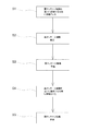
 first massage mechanism 31 and the second massage mechanism 51 will be described.

[動作1]
図20は動作1のフロー図である。図21は動作1の説明図であり、(a)は第1マッサージ機構31が進出し第2マッサージ機構51が後退した状態、(b)は第1マッサージ機構31が後退し第2マッサージ機構51が進出した状態を示している。
動作1は、第1マッサージ機構31と第2マッサージ機構51を、タイミングをずらして進退させる動作であり、マッサージモータ43,63の駆動による施療子34,54の動作を含めることが好ましい。以下、図21に示すとおり、第1マッサージユニット8を首位置に配置し、第2マッサージユニット9を肩の背面位置に配置した状態で、動作1を行う場合について例示する。
[Operation 1]
FIG. 20 is a flowchart of the operation 1. FIG. 21 is an explanatory diagram of the operation 1. FIG. 21A is a state in which the first massage mechanism 31 is advanced and the second massage mechanism 51 is retracted, and FIG. 21B is a state in which the first massage mechanism 31 is retracted and the second massage mechanism 51 is retracted. Indicates the state of advance.
The operation 1 is an operation of moving the first massage mechanism 31 and the second massage mechanism 51 forward and backward at different timings, and preferably includes the operations of the treatment elements 34 and 54 driven by the massage motors 43 and 63. Hereinafter, as illustrated in FIG. 21, the case where the first massage unit 8 is arranged at the neck position and the second massage unit 9 is arranged at the back position of the shoulder is illustrated as an example in which the operation 1 is performed.

図20に示すとおり、まず第1マッサージ機構31を第2マッサージ機構51に対して相対的に進出させる(ステップS1)。続いて、第1マッサージ機構31の前後位置を維持した状態で、第2マッサージ機構51を進出させる(ステップS2)。続いて、第2マッサージ機構51の前後位置を維持した状態で、第1マッサージ機構31を第2マッサージ機構51に対して相対的に後退させる(ステップS3)。続いて、第1マッサージ機構31の前後位置を維持した状態で、第2マッサージ機構51を後退させる(ステップS4)。このステップS1〜S4のサイクルを所定時間繰り返す。なお、このステップS1〜S4においては、第2マッサージ機構51から先に進出させてもよい。また、各マッサージユニット8,9を配置する位置は特に限定されず、例えば、第1マッサージユニット8を首位置に配置し、第2マッサージユニット9を腰位置に配置してもよい。   As shown in FIG. 20, first, the first massage mechanism 31 is advanced relative to the second massage mechanism 51 (step S1). Then, the 2nd massage mechanism 51 is advanced in the state which maintained the front-back position of the 1st massage mechanism 31 (step S2). Subsequently, the first massage mechanism 31 is moved backward relative to the second massage mechanism 51 in a state where the front and rear positions of the second massage mechanism 51 are maintained (step S3). Subsequently, the second massage mechanism 51 is moved backward while maintaining the front and back positions of the first massage mechanism 31 (step S4). The cycle of steps S1 to S4 is repeated for a predetermined time. In steps S1 to S4, the second massage mechanism 51 may be advanced first. Moreover, the position which arrange | positions each massage unit 8 and 9 is not specifically limited, For example, the 1st massage unit 8 may be arrange | positioned in a neck position, and the 2nd massage unit 9 may be arrange | positioned in a waist position.

ステップS1〜S4においては、マッサージモータ43,63を駆動して施療子34,54に揉み動作又は叩き動作を含むマッサージを行わせることが好ましく、前記マッサージを常時行っていてもよい。あるいは、前記マッサージは断続的に行っていてもよく、例えば、各マッサージ機構31,51が進出しているときに前記マッサージを行い、各マッサージ機構31,51が後退しているときは前記マッサージを停止してもよい。また、マッサージ機構31,51の進出又は後退と前記マッサージを同期させてもよく、この場合は、あたかもマッサージ師が力加減を変更しながら揉み動作又は叩き動作を行うかのような体感を得ることができる。あるいは、マッサージ機構31,51の進出又は後退と、左右対の施療子34,54を近接させる動作と、を同期させてもよく、この場合は、あたかもマッサージ師が被施療部を掴みながら押し込む、又は被施療部を掴みながら引くかのような体感を得ることができる。なお、ここでいう「同期」とは、マッサージ機構31,51の進出又は後退を行う進退駆動部15,16と、揉み動作、叩き動作、又は対の施療子を近接させる動作を行うマッサージモータ43,63と、の駆動は後先を問わず並行して行われていればよく、更にはマッサージ機構31,51の進出又は後退完了後にマッサージモータ43,63を駆動させる場合も含む。   In steps S1 to S4, it is preferable to drive the massage motors 43 and 63 to cause the treatment elements 34 and 54 to perform massage including a squeezing operation or a hitting operation, and the massage may be performed constantly. Alternatively, the massage may be performed intermittently. For example, the massage is performed when the massage mechanisms 31 and 51 are advanced, and the massage is performed when the massage mechanisms 31 and 51 are retracted. You may stop. Further, the advancement or retreat of the massage mechanisms 31 and 51 may be synchronized with the massage, and in this case, it is possible to obtain a sensation as if the masseur performs a rubbing operation or a tapping operation while changing the force. Can do. Alternatively, the advancement or retreat of the massage mechanisms 31 and 51 and the operation of bringing the pair of left and right treatment elements 34 and 54 close to each other may be synchronized. In this case, the massager pushes in while holding the treatment part. Alternatively, it is possible to obtain a sensation of pulling while grasping the treatment area. The term “synchronization” as used herein refers to the advancing / retreating drive units 15 and 16 for advancing or retreating the massage mechanisms 31 and 51, and a massage motor 43 for performing a kneading operation, a hitting operation, or an operation for bringing a pair of treatment elements in proximity. , 63 may be driven in parallel regardless of the destination, and further includes the case where the massage motors 43, 63 are driven after the advancement or retreat of the massage mechanisms 31, 51 is completed.

また、一方のマッサージ機構の進出に同期して他方のマッサージ機構を後退させるように、各マッサージ機構31,51を交互に進退させてもよく、この場合は、あたかもマッサージ師が左手と右手を交互に切り替えてマッサージを行うかのような体感を得ることができる。また、一方のマッサージ機構を進出させた状態で、他方のマッサージ機構は進出及び後退を所定時間繰り返してもよく、この場合は、あたかもマッサージ師が一方の手を被施療部に添えて、他方の手で指圧を繰り返すかのような体感を得ることができる。   In addition, the massage mechanisms 31 and 51 may be alternately advanced and retracted so that the other massage mechanism is retracted in synchronization with the advancement of one massage mechanism. In this case, the masseur alternates between the left hand and the right hand. You can get a sensation as if you are switching to massage. In addition, with one massage mechanism advanced, the other massage mechanism may repeat advancement and retraction for a predetermined time. In this case, the masseur attaches one hand to the treatment area and the other You can get the feeling of repeating shiatsu with your hands.

また、ステップS1〜S4においては、昇降モータ35,55を駆動して各マッサージユニット8,9を昇降させてもよく、例えば、マッサージ機構31,51の進出とマッサージユニット8,9の上昇又は下降を同期させてもよく、この場合は、あたかもマッサージ師が被施療部を押し上げ又は押し下げるかのような体感を得ることができる。なお、この動作は、左右対の施療子を近接させる動作も同期させることが好ましい。   In steps S1 to S4, the lifting / lowering motors 35 and 55 may be driven to move the massage units 8 and 9 up and down. For example, the massage mechanisms 31 and 51 advance and the massage units 8 and 9 move up or down. May be synchronized, and in this case, it is possible to obtain a sensation as if the masseur pushes up or down the treated portion. In addition, it is preferable that this operation | movement synchronizes also the operation | movement which makes a left-right paired treatment element adjoin.

このように動作1は、各マッサージ機構31,51がタイミングをずらして進退してマッサージを行うため、あたかもマッサージ師が両手を使ってマッサージを行うかのような臨場感のある体感を得ることができる。特に、前記マッサージとして揉み動作を行う場合は、一方のマッサージ機構の左右対の施療子が、マッサージ師の左手の親指と他の指での揉み動作を模擬し、他方のマッサージ機構の左右対の施療子が、マッサージ師の右手の親指と他の指での揉み動作を模擬することができる。また、動作1は、両マッサージ機構31,51を上下方向に近づけた状態で行うことにより臨場感が顕著となるため、センサ70に基づいて、前述した近接状態又は近接前状態で行うことが好ましい。   As described above, in the operation 1, the massage mechanisms 31 and 51 advance and retreat at different timings to perform massage, so that it is possible to obtain a realistic sensation as if the masseur performs massage using both hands. it can. In particular, when the massage operation is performed as the massage, the pair of left and right treatment elements of one massage mechanism simulate the massage operation of the masseur's left hand and the other finger, and the other massage mechanism The treatment device can simulate the massaging operation with the thumb and other fingers of the masseur's right hand. In addition, the action 1 is performed in a state in which both the massage mechanisms 31 and 51 are close to each other in the vertical direction, so that a sense of realism becomes remarkable. Therefore, it is preferable to perform the operation 1 in the proximity state or the state before the proximity based on the sensor 70. .

また、前述した実施形態では、各マッサージ機構31,51を互いにタイミングをずらして進出又は後退させることで臨場感のある体感を実現したが、各マッサージ機構31,51の進出又は後退させる速度を互いに異ならせても同様の体感を得ることができる。例えば、第1マッサージ機構31の進出速度を第2マッサージ機構51の進出速度よりも相対的に速くした場合は、各マッサージ機構31,51が同時に進出を開始したとしても、第1マッサージ機構31の施療子34で被施療部を押し込んだ後、少し遅れて第2マッサージ機構51の施療子54で被施療部を押し込むこととなる。従って、あたかもマッサージ師が左手と右手を被施療部に順次押し込むかのような体感を得ることができる。   Moreover, in embodiment mentioned above, although the massage mechanism 31 and 51 mutually shifted timing, it advanced and retracted | achieved and the realistic sensation was implement | achieved, but the speed which each massage mechanism 31 and 51 advances or retracts mutually A similar experience can be obtained even if they are different. For example, if the advancement speed of the first massage mechanism 31 is relatively faster than the advancement speed of the second massage mechanism 51, even if each of the massage mechanisms 31, 51 starts to advance simultaneously, After the treatment part 34 is pushed in with the treatment element 34, the treatment part is pushed in with the treatment element 54 of the second massage mechanism 51 with a slight delay. Therefore, it is possible to obtain a sensation as if the masseur pushes the left hand and the right hand sequentially into the treatment area.

[動作2]
図22は動作2及び動作3のフロー図である。図23は動作2及び動作3の説明図であり、(a)は第1及び第2マッサージ機構31,51が後退した状態、(b)は第1及び第2マッサージ機構31,51が進出した状態、(c)は第1マッサージ機構31が進出し第2マッサージ機構51が後退した状態を示している。なお、図23において、斜線を付した施療子34,54a,54bは進出した状態を示しており、斜線を付していない施療子34,54a,54bは後退した状態を示している。
[Operation 2]
FIG. 22 is a flowchart of operations 2 and 3. 23A and 23B are explanatory diagrams of the operation 2 and the operation 3. FIG. 23A is a state where the first and second massage mechanisms 31 and 51 are retracted, and FIG. 23B is a state where the first and second massage mechanisms 31 and 51 are advanced. The state (c) shows a state in which the first massage mechanism 31 has advanced and the second massage mechanism 51 has retracted. In FIG. 23, the treatment elements 34, 54a, and 54b with hatched lines indicate the advanced state, and the treatment elements 34, 54a, and 54b without hatched line indicate the retracted state.

動作2は、第1マッサージ機構31の施療子34と第2マッサージ機構51の施療子54を被施療部に対して進出させる動作である。以下、図23に示すとおり、1マッサージユニット8を肩の背面位置に配置し、第2マッサージユニット9を背中上部に配置した状態で、動作2を行う場合について例示する。   The operation 2 is an operation in which the treatment element 34 of the first massage mechanism 31 and the treatment element 54 of the second massage mechanism 51 are advanced to the treatment portion. Hereinafter, as shown in FIG. 23, the case where the operation 2 is performed in the state where the first massage unit 8 is disposed at the back position of the shoulder and the second massage unit 9 is disposed at the upper back is illustrated.

図22に示すとおり、まず各マッサージユニット8,9を昇降させて、身長方向において近接した状態とする(ステップS1)。この例では、第1マッサージユニット8を肩の背面位置に配置し、第2マッサージユニット9を背中上部に配置している。従って、図23に示すように施療子34と上施療子54aが身長方向において近接した状態となる。続いて、マッサージモータ43,63を駆動し、図23(a)に示すように第1マッサージ機構31の施療子34と第2マッサージ機構51の施療子54の左右方向における位置を異ならせる(ステップS2)。続いて、進退駆動部15,16を駆動して、図23(b)に示すように第1マッサージ機構31及び第2マッサージ機構51を進出させる(ステップS3)。   As shown in FIG. 22, first, the massage units 8 and 9 are moved up and down to be close to each other in the height direction (step S1). In this example, the first massage unit 8 is disposed at the back position of the shoulder, and the second massage unit 9 is disposed at the upper back. Therefore, as shown in FIG. 23, the treatment element 34 and the upper treatment element 54a are close to each other in the height direction. Subsequently, the massage motors 43 and 63 are driven, and the positions of the treatment element 34 of the first massage mechanism 31 and the treatment element 54 of the second massage mechanism 51 in the left-right direction are made different as shown in FIG. S2). Subsequently, the advance / retreat driving units 15 and 16 are driven to advance the first massage mechanism 31 and the second massage mechanism 51 as shown in FIG. 23B (step S3).

なお、ステップS1においては、両マッサージユニット8,9の上下間隔をセンサ70に基づいて決定すればよく、例えば、前述した近接状態又は近接前状態とすればよい。また、ステップS2においては、各施療子34,54の左右位置は、幅センサ46,66に基づいて決定すればよい。また、ステップS1とステップS2は並行して行ってもよい。また、ステップS3においては、第1マッサージ機構31及び第2マッサージ機構51は、同時に進出させてもよいし、タイミングをずらして進出させてもよい。   In step S1, the vertical distance between the massage units 8 and 9 may be determined based on the sensor 70, for example, the proximity state or the pre-proximity state described above. In step S2, the left and right positions of the treatment elements 34 and 54 may be determined based on the width sensors 46 and 66. Further, step S1 and step S2 may be performed in parallel. Moreover, in step S3, the 1st massage mechanism 31 and the 2nd massage mechanism 51 may be advanced simultaneously, and may be advanced by shifting timing.

ステップS3においては、マッサージモータ43,63を駆動させて揉み動作又は叩き動作を行ってもよい。例えば、背凭れ部3において、一方のマッサージ機構に揉み動作を行わせ、それと並行して他方のマッサージ機構に叩き動作を含む動作を行わせることが好ましい。このように動作させることで、あたかも2人以上のマッサージ師により、上半身に対して異なる種類のマッサージを行われているかのような体感を与えることができる。なお、マッサージ師は片手で揉み動作を行うことはできても、片手で叩き動作を行うことはできないため、1人のマッサージ師では揉み動作と叩き動作を並行して行うことはできない。   In step S3, the massage motors 43 and 63 may be driven to perform a kneading operation or a tapping operation. For example, in the backrest part 3, it is preferable to cause one massage mechanism to perform a kneading operation and to cause the other massage mechanism to perform an operation including a hitting operation in parallel therewith. By operating in this way, it is possible to give a sensation as if different types of massage are being performed on the upper body by two or more masseurs. In addition, even if a masseur can perform a rubbing operation with one hand, it cannot perform a striking operation with one hand, so a single masseur cannot perform a rubbing operation and a striking operation in parallel.

このように動作2は、第1マッサージ機構31の施療子34と第2マッサージ機構51の施療子54(上施療子54a)が、左右方向に並んだ状態となるため、あたかもマッサージ師が両手を使って親指と他の指でマッサージ(指圧)を行うかのような臨場感のある体感を得ることができる。すなわち、図23に示す状態では、左右内側に位置する施療子34が親指に相当し、左右外側に位置する上施療子54a又は下施療子54bがその他の指に相当する。また、前述した実施形態では、第1マッサージ機構31と第2マッサージ機構51が近接した状態で動作2を行う場合について説明したが、離反した状態で動作2を行ってもよい。この場合、例えば、下側に位置する施療子54(上施療子54a又は下施療子54b)が親指に相当し、上側に位置する施療子34が他の指に相当する。   As described above, in the operation 2, since the treatment element 34 of the first massage mechanism 31 and the treatment element 54 (upper treatment element 54a) of the second massage mechanism 51 are arranged in the left-right direction, it is as if the masseur holds both hands. You can use it to get a realistic sensation as if you were massaged with your thumb and other fingers. That is, in the state shown in FIG. 23, the treatment element 34 located on the left and right inner sides corresponds to the thumb, and the upper treatment element 54a or the lower treatment element 54b located on the left and right outer sides corresponds to the other fingers. Moreover, although embodiment mentioned above demonstrated the case where operation | movement 2 was performed in the state which the 1st massage mechanism 31 and the 2nd massage mechanism 51 adjoined, you may perform operation | movement 2 in the state which left | separated. In this case, for example, the lower treatment element 54 (upper treatment element 54a or lower treatment element 54b) corresponds to the thumb, and the upper treatment element 34 corresponds to the other finger.

[動作3]
動作3は、第1マッサージ機構31の施療子34と第2マッサージ機構51の施療子54について、左右方向における位置を異ならせ、かつ進出させた状態から一方のマッサージ機構の施療子を後退させる動作である。以下、図22に示すとおり、動作2に引き続いて動作3を行う場合について例示する。
[Operation 3]
Operation 3 is an operation in which the treatment element 34 of the first massage mechanism 31 and the treatment element 54 of the second massage mechanism 51 are moved in the left-right direction, and the treatment element of one massage mechanism is moved backward from the advanced state. It is. Hereinafter, as illustrated in FIG. 22, the case where the operation 3 is performed following the operation 2 will be illustrated.

動作2のステップS3に引き続いて、進退駆動部を駆動していずれか一方のマッサージ機構を後退させる(ステップS4)。図23に示す例では、進退駆動部16を駆動して、第2マッサージ機構51を後退させている。そうすると、進出している第1マッサージ機構31の施療子34に被施療部が強く当接し、あたかも施療子34によって指圧されているかのような体感を得ることができる。なお、動作3は、両マッサージ機構31,51が近接した状態で行うことにより指圧の体感が顕著となるため、センサ70に基づいて、前述した近接状態又は近接前状態で行うことが好ましい。また、動作2及び動作3においては、各マッサージユニット8,9を配置する位置は特に限定されず、例えば、第1マッサージユニット8を首又は背中位置に配置し、第2マッサージユニット9を腰位置に配置してもよい。   Subsequent to Step S3 of Operation 2, the advance / retreat driving unit is driven to retract one of the massage mechanisms (Step S4). In the example shown in FIG. 23, the advance / retreat drive unit 16 is driven to retract the second massage mechanism 51. If it does so, a to-be-treated part will contact | abut strongly to the treatment element 34 of the 1st massage mechanism 31 which is advancing, and a feeling as if it is being acupressure by the treatment element 34 can be acquired. In addition, since the bodily sensation of acupressure becomes remarkable when the operation 3 is performed in a state where both the massage mechanisms 31 and 51 are close to each other, it is preferable to perform the operation 3 in the above-described proximity state or the state before proximity based on the sensor 70. Moreover, in the operation | movement 2 and the operation | movement 3, the position which arrange | positions each massage unit 8 and 9 is not specifically limited, For example, the 1st massage unit 8 is arrange | positioned in a neck or a back position, and the 2nd massage unit 9 is a waist position. You may arrange in.

[動作4]
図24は動作4の説明図である。なお、図24においては、理解を容易にするために、下施療子54bの図示を省略している。
動作4は、第1マッサージ機構31の施療子34と第2マッサージ機構51の施療子54について、それぞれ異なる速度で揉み動作を行う動作であり、各マッサージ機構31,51を身長方向において近接した状態として行うことが好ましい。
[Operation 4]
FIG. 24 is an explanatory diagram of operation 4. In FIG. 24, the illustration of the lower treatment element 54b is omitted for easy understanding.
The operation 4 is an operation in which the massaging element 34 of the first massage mechanism 31 and the massaging element 54 of the second massage mechanism 51 are squeezed at different speeds, and the massage mechanisms 31 and 51 are close to each other in the height direction. It is preferable to carry out as

まず各マッサージユニット8,9を昇降させて、身長方向において近接した状態とする。続いて、各マッサージモータ43,63を一方向に連続的に駆動して、第1マッサージ機構31の施療子34と第2マッサージ機構51の施療子54により揉み動作を行わせる。この揉み動作は、それぞれのマッサージモータ43,63を異なる速度で駆動することにより、それぞれの揉み軸41,61を異なる速度で回転させて行う。図24に示す例では、揉み軸41の回転を相対的に速くしている。なお、両マッサージユニット8,9の上下間隔は、センサ70に基づいて決定すればよく、例えば、前述した近接状態又は近接前状態とすればよい。   First, the massage units 8 and 9 are moved up and down to be close to each other in the height direction. Subsequently, the massage motors 43 and 63 are continuously driven in one direction, and a massage operation is performed by the treatment element 34 of the first massage mechanism 31 and the treatment element 54 of the second massage mechanism 51. This kneading operation is performed by driving the massage motors 43 and 63 at different speeds to rotate the kneading shafts 41 and 61 at different speeds. In the example shown in FIG. 24, the rotation of the kneading shaft 41 is made relatively fast. In addition, what is necessary is just to determine the up-and-down space | interval of both the massage units 8 and 9 based on the sensor 70, for example, may be the proximity | contact state mentioned above or the state before proximity | contact.

このように動作4は、各マッサージ機構31,51の施療子34,54がループ状の軌跡を1周するサイクルを繰り返して揉み動作を行うわけであるが、一方のマッサージ機構の施療子を視点とすると、各サイクルで他方のマッサージ機構の施療子との位置関係が異なる。例えば、第1マッサージ機構31の施療子34を視点とすると、1サイクル目の対の施療子34が最も離反した状態では、第2マッサージ機構51の対の施療子54は揉み動作の軌跡上における上端に位置しているが、2サイクル目の対の施療子34が最も離反した状態では、第2マッサージ機構51の対の施療子54は揉み動作の軌跡上における下端に位置している。このように動作4は、第1マッサージ機構31の施療子34と第2マッサージ機構51の施療子54と、による上下方向からの揉み動作を時間の経過とともに変化させることができ、マッサージ効果が高まる。   As described above, in the operation 4, the massage elements 34 and 54 of the massage mechanisms 31 and 51 repeat the cycle of making one round of the loop-shaped trajectory and perform the massage operation. Then, in each cycle, the positional relationship with the treatment element of the other massage mechanism is different. For example, when the treatment element 34 of the first massage mechanism 31 is taken as a viewpoint, the pair of treatment elements 54 of the second massage mechanism 51 are on the trajectory of the massage operation in a state where the pair of treatment elements 34 in the first cycle are most separated. Although located at the upper end, in the state in which the pair of treatment elements 34 in the second cycle are farthest apart, the pair of treatment elements 54 of the second massage mechanism 51 is located at the lower end on the trajectory of the massage operation. Thus, the operation 4 can change the massage operation from the up and down direction by the treatment element 34 of the first massage mechanism 31 and the treatment element 54 of the second massage mechanism 51 with the passage of time, and the massage effect is enhanced. .

[動作5]
図25は動作5の説明図であり、(a)は第1及び第2マッサージ機構31,51が後退した状態、(b)は第1マッサージ機構31が後退し第2マッサージ機構51が進出した状態を示している。
図25に示すとおり、動作5は、第1マッサージユニット8を肩位置に配置し、第2マッサージユニット9を腰位置に配置した状態で、第2マッサージ機構51を進出させる動作であり、マッサージモータ43の駆動による施療子34の動作を含めることが好ましい。第2マッサージ機構51を腰位置で進出させることにより、腰が前方に押し出されて上半身が仰け反るような姿勢となる。従って、第1マッサージ機構31の施療子34に肩が強く当接する。このとき第1マッサージ機構31の施療子34に揉み動作又は叩き動作を行わせていれば、マッサージ効果が高まる。
[Operation 5]
FIG. 25 is an explanatory diagram of the operation 5. FIG. 25A is a state in which the first and second massage mechanisms 31 and 51 are retracted, and FIG. 25B is a state in which the first massage mechanism 31 is retracted and the second massage mechanism 51 is advanced. Indicates the state.
As shown in FIG. 25, the operation 5 is an operation of moving the second massage mechanism 51 in a state where the first massage unit 8 is arranged at the shoulder position and the second massage unit 9 is arranged at the waist position, and the massage motor It is preferable to include the operation of the treatment element 34 by driving 43. By advancing the second massage mechanism 51 at the waist position, the posture is such that the waist is pushed forward and the upper body is turned upside down. Therefore, the shoulder strongly contacts the treatment element 34 of the first massage mechanism 31. At this time, if the therapeutic element 34 of the first massage mechanism 31 is squeezed or hit, the massage effect is enhanced.

[動作6]
図26は動作6の説明図であり、(a)は第1マッサージユニット8が肩位置に配置され第2マッサージユニット9が腰位置に配置された状態、(b)は第1マッサージユニット8が肩位置に配置され第2マッサージユニット9が背中位置まで上昇した状態を示している。
図26に示すとおり、動作6は、第1マッサージユニット8を肩位置に配置した状態で、第2マッサージユニット9を身長方向に上昇させる動作であり、マッサージモータ43の駆動による施療子34の動作を含めることが好ましい。第2マッサージユニット9を上昇させることにより、上半身が持ち上げられる。従って、第1マッサージ機構31の施療子34に肩が強く当接する。このとき第1マッサージ機構31の施療子34に揉み動作又は叩き動作を行わせていれば、マッサージ効果が高まる。
[Operation 6]
26A and 26B are explanatory views of the operation 6. FIG. 26A shows a state where the first massage unit 8 is arranged at the shoulder position and the second massage unit 9 is arranged at the waist position, and FIG. 26B shows the state where the first massage unit 8 is arranged. The state which has been arrange | positioned in the shoulder position and the 2nd massage unit 9 rose to the back position is shown.
As shown in FIG. 26, the operation 6 is an operation of raising the second massage unit 9 in the height direction with the first massage unit 8 placed at the shoulder position, and the operation of the treatment element 34 by driving the massage motor 43. Is preferably included. The upper body is lifted by raising the second massage unit 9. Therefore, the shoulder strongly contacts the treatment element 34 of the first massage mechanism 31. At this time, if the therapeutic element 34 of the first massage mechanism 31 is squeezed or hit, the massage effect is enhanced.

[動作7]
図27は動作7の説明図であり、(a)は第1マッサージ機構31が進出して首を挟持し第2マッサージ機構51が肩位置に配置された状態、(b)は第1マッサージ機構31が進出して首を挟持し第2マッサージ機構51が腰位置まで下降した状態を示している。
動作7は、一方のマッサージ機構の対の施療子により被施療部を挟持した状態で、他方のマッサージ機構を身長方向に上昇又は下降させる動作である。図27に示す例では、第1マッサージ機構31を進出させ対の施療子34を近接させて首を挟持した状態で、第2マッサージユニット9を下降させている。第2マッサージユニット9を下降させることにより、上半身が下方へ引っ張られる。従って、首は第1マッサージ機構31の施療子34により挟持されているため、首を伸ばすストレッチ効果を得ることができる。また、第1マッサージ機構により首を挟持した状態で、第2マッサージユニット9に上昇及び下降を繰り返し行わせれば、あたかもマッサージ師が一方の手を添えて首を固定した状態で、他方の手で被施療部をさすったり伸ばしたりするかのような体感を得ることができる。
[Operation 7]
FIG. 27 is an explanatory diagram of the operation 7. FIG. 27A shows a state in which the first massage mechanism 31 has advanced to pinch the neck and the second massage mechanism 51 is disposed at the shoulder position, and FIG. 27B shows the first massage mechanism. 31 shows a state in which the second massage mechanism 51 has been lowered to the waist position by advancing and pinching the neck.
The operation 7 is an operation of raising or lowering the other massage mechanism in the height direction in a state where the treatment portion is held by the pair of treatment elements of the one massage mechanism. In the example shown in FIG. 27, the second massage unit 9 is lowered in a state where the first massage mechanism 31 is advanced, the pair of treatment elements 34 are brought close to each other, and the neck is clamped. By lowering the second massage unit 9, the upper body is pulled downward. Therefore, since the neck is clamped by the treatment element 34 of the first massage mechanism 31, a stretch effect for extending the neck can be obtained. Also, if the second massage unit 9 is repeatedly raised and lowered while the neck is clamped by the first massage mechanism, it is as if the masseur attached one hand and the neck was fixed with the other hand. A feeling of touching or extending the treatment area can be obtained.

動作7においては、各マッサージユニット8,9を配置する位置は特に限定されない。また、被施療部を挟持するマッサージ機構と上昇又は下降させるマッサージ機構は適宜選択することができる。例えば、第2マッサージユニット9を腰位置に配置して対の施療子54により腰を挟持した状態で、第1マッサージユニット8を背中位置で上昇又は下降させてもよい。   In the operation 7, the positions where the massage units 8 and 9 are arranged are not particularly limited. Moreover, the massage mechanism which clamps a to-be-treated part and the massage mechanism which raises or falls can be selected suitably. For example, the first massage unit 8 may be raised or lowered at the back position in a state where the second massage unit 9 is disposed at the waist position and the waist is sandwiched between the pair of treatment elements 54.

[動作8]
図28は動作8の説明図であり、(a)は第1マッサージ機構31が揉み動作を行い、第2マッサージ機構51が上昇過程の状態であり、(b)は第1マッサージ機構31が揉み動作を行い、第2マッサージ機構51が下降過程の状態を示している。動作8は、一方のマッサージ機構に揉み動作又は叩き動作を行わせ、他方のマッサージ機構を上昇又は下降させる動作である。以下、図28に基づいて、第1マッサージ機構31を前記一方のマッサージ機構として揉み動作を行わせ、第2マッサージ機構51を前記他方のマッサージ機構として上昇又は下降させる場合について例示する。
[Operation 8]
28A and 28B are explanatory diagrams of the operation 8. FIG. 28A shows the state in which the first massage mechanism 31 performs the kneading operation, the second massage mechanism 51 is in the ascending process, and FIG. The operation | movement is performed and the 2nd massage mechanism 51 has shown the state of the descent | fall process. The operation 8 is an operation of causing one massage mechanism to perform a rubbing operation or a hitting operation and raising or lowering the other massage mechanism. Hereinafter, based on FIG. 28, the case where the first massage mechanism 31 is used as the one massage mechanism and the second massage mechanism 51 is raised or lowered as the other massage mechanism is illustrated.

図28(a)に示すとおり、第1マッサージ機構31に向かって第2マッサージ機構51を上昇させて近接させていくことにより、被施療部の筋肉が第1マッサージ機構31側に寄せられることとなり、この寄せた筋肉を第1マッサージ機構31の対の施療子34により揉むことができる。一方、図28(b)に示すとおり、第1マッサージ機構31から第2マッサージ機構51を下降させて離反させていくことにより、被施療部の筋肉が引っ張られることとなり、この引っ張られた筋肉を第1マッサージ機構31の対の施療子34により揉むことができる。しかも、第2マッサージ機構51の上昇又は下降によって被施療部をさすることで血行を促進することができ、血行を高めた被施療部に対して第1マッサージ機構31が揉み動作を行うことでマッサージ効果が更に高まる。なお、動作8においては、第1マッサージ機構31を上昇又は下降させ、第2マッサージ機構51に揉み動作又は叩き動作を行わせてもよい。   As shown in FIG. 28 (a), the second massage mechanism 51 is raised toward the first massage mechanism 31 so as to approach the first massage mechanism 31, so that the muscle of the treatment portion is brought closer to the first massage mechanism 31 side. The gathered muscles can be massaged by the pair of treatment elements 34 of the first massage mechanism 31. On the other hand, as shown in FIG. 28 (b), by lowering the second massage mechanism 51 from the first massage mechanism 31 and separating it, the muscles of the treatment site are pulled, and the pulled muscles are It can be massaged by the pair of treatment elements 34 of the first massage mechanism 31. In addition, blood circulation can be promoted by pointing the treatment portion by raising or lowering the second massage mechanism 51, and the first massage mechanism 31 performs a kneading operation on the treatment portion with increased blood circulation. The massage effect is further enhanced. In operation 8, the first massaging mechanism 31 may be raised or lowered to cause the second massaging mechanism 51 to perform a kneading operation or a tapping operation.

[動作9]
図29は動作9及び動作10のフロー図である。
動作9は、第1マッサージ機構31と第2マッサージ機構51を身長方向に沿って互いに近接する方向に移動させる動作と、第1及び第2マッサージ機構31,51の施療子34,54を被施療部に対して進出させる動作と、を同期させる動作である。図29に示すとおり、まず各マッサージユニット8,9を互いに近接する方向に移動させる(ステップS1)。このステップS1の動作は、各マッサージユニット8,9の相対位置が近接状態又は近接前状態となるまで継続して行われる。ステップS1の完了後、又はステップS1と並行して、第1及び第2マッサージ機構31,51の施療子34,54を進出させる(ステップS2)。このように動作させることにより、マッサージ機構31,51の身長方向に沿った移動により背筋が伸ばされつつ、施療子34,54の進出により上半身を反らすことができ、マッサージ効果が高まる。そして、ステップS2の完了後に、第1及び第2マッサージ機構31,51の施療子34,54を後退させる(ステップS3)。なお、ステップS1においては、腰位置を目標位置として第1及び第2マッサージ機構31,51を互いに近接させていくのが好ましく、この場合は上半身を反らす効果が高まる。
[Operation 9]
FIG. 29 is a flowchart of the operation 9 and the operation 10.
The operation 9 is an operation in which the first massage mechanism 31 and the second massage mechanism 51 are moved in the direction close to each other along the height direction, and the treatment elements 34 and 54 of the first and second massage mechanisms 31 and 51 are treated. This is an operation of synchronizing the operation to advance the part. As shown in FIG. 29, first, the massage units 8 and 9 are moved in a direction approaching each other (step S1). The operation in step S1 is continuously performed until the relative positions of the massage units 8 and 9 are in the proximity state or the pre-proximity state. After the completion of step S1, or in parallel with step S1, the treatment elements 34, 54 of the first and second massage mechanisms 31, 51 are advanced (step S2). By operating in this way, the upper body can be warped by the advancement of the treatment elements 34 and 54 while the back muscles are stretched by the movement of the massage mechanisms 31 and 51 along the height direction, and the massage effect is enhanced. And after completion of step S2, the treatment elements 34, 54 of the first and second massage mechanisms 31, 51 are moved backward (step S3). In step S1, it is preferable to bring the first and second massage mechanisms 31, 51 close to each other with the waist position as the target position. In this case, the effect of warping the upper body is enhanced.

[動作10]
動作10は、第1マッサージ機構31と第2マッサージ機構51を身長方向に沿って互いに離反する方向に移動させる動作と、第1及び第2マッサージ機構31,51の施療子34,54を被施療部に対して進出させる動作と、を同期させる動作である。以下、図29に示すとおり、動作9に引き続いて動作10を行う場合について例示する。
動作9のステップS3に引き続いて、近接状態又は近接前状態にある第1及び第2マッサージユニット8,9を互いに離反する方向に移動させる(ステップS4)。このステップS4の動作は、第1マッサージユニット8が首位置となり、第2マッサージユニット9が昇降範囲の下限位置となるまで継続して行われる。そして、ステップS4と並行して、第1及び第2マッサージ機構31,51の施療子34,54を進出させる(ステップS5)。このように動作させることにより、施療子34,54の進出により上半身を反らしながら、マッサージ機構31,51の身長方向に沿った離反動作により上半身を引き伸ばすことができ、マッサージ効果が高まる。
[Operation 10]
The operation 10 includes an operation of moving the first massage mechanism 31 and the second massage mechanism 51 in the direction away from each other along the height direction, and treatment of the treatment elements 34 and 54 of the first and second massage mechanisms 31 and 51. This is an operation of synchronizing the operation to advance the part. Hereinafter, as illustrated in FIG. 29, a case where the operation 10 is performed subsequent to the operation 9 will be illustrated.
Subsequent to step S3 of operation 9, the first and second massage units 8 and 9 in the proximity state or the pre-proximity state are moved away from each other (step S4). The operation in step S4 is continuously performed until the first massage unit 8 is in the neck position and the second massage unit 9 is in the lower limit position of the lifting range. In parallel with step S4, the treatment elements 34, 54 of the first and second massage mechanisms 31, 51 are advanced (step S5). By operating in this way, the upper body can be stretched by the separation operation along the height direction of the massage mechanisms 31 and 51 while the upper body is warped by the advancement of the treatment elements 34 and 54, and the massage effect is enhanced.

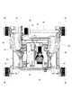
[他の実施形態に係るマッサージユニットの構成]
以下、他の実施形態に係るマッサージユニット100について説明する。図30は他の実施形態に係るマッサージユニット100の正面図である。マッサージユニット100は、前述したマッサージ機構31及び第2マッサージ機構51をまとめて単一の本体フレーム110に設けている。すなわち、マッサージ機構31,51及びマッサージ機構31,51を支持する支持フレーム32,52は、前述した構成と同一であるため、以下では同一符号を付してその説明を省略する。
[Composition of massage unit concerning other embodiments]
Hereinafter, a massage unit 100 according to another embodiment will be described. FIG. 30 is a front view of a massage unit 100 according to another embodiment. In the massage unit 100, the massage mechanism 31 and the second massage mechanism 51 described above are collectively provided in a single main body frame 110. That is, the massage mechanisms 31 and 51 and the support frames 32 and 52 that support the massage mechanisms 31 and 51 have the same configuration as described above.

図30に示すとおり、マッサージユニット100は、相対的に上側に配置される第1マッサージ機構31と相対的に下側に配置される第2マッサージ機構51を備えて、背凭れ部3に設けられている。マッサージユニット100は、主として、ガイド機構3bによって昇降可能に支持された本体フレーム110と、第1マッサージ機構31及び第2マッサージ機構51と、各マッサージ機構31,51を支持する支持フレーム32,52と、各マッサージ機構31,51を被施療部に対して進退させる進退駆動部15,16と、本体フレーム110と支持フレーム32,52を連結して前後方向に揺動するリンク33,53と、を有して構成されている。   As shown in FIG. 30, the massage unit 100 includes a first massage mechanism 31 that is relatively disposed on the upper side and a second massage mechanism 51 that is disposed relatively on the lower side, and is provided on the backrest 3. ing. The massage unit 100 mainly includes a main body frame 110 supported by the guide mechanism 3b so as to be movable up and down, a first massage mechanism 31 and a second massage mechanism 51, and support frames 32 and 52 that support the massage mechanisms 31 and 51. The advancing / retreating drive parts 15 and 16 for advancing and retracting the massage mechanisms 31 and 51 with respect to the treatment part, and the links 33 and 53 that connect the main body frame 110 and the support frames 32 and 52 and swing in the front-rear direction. It is configured.

マッサージユニット100は、昇降モータ111と、昇降軸112と、昇降軸112の両端に取り付けられたピニオン39と、を備え、昇降モータ111を駆動することにより昇降軸112が回転してマッサージユニット100が身長方向に沿って昇降する。施療子34は、マッサージモータ43の駆動により、揉み動作又は叩き動作を行い、施療子54は、マッサージモータ63の駆動により揉み動作を行うことができる。   The massage unit 100 includes a lift motor 111, a lift shaft 112, and pinions 39 attached to both ends of the lift shaft 112. By driving the lift motor 111, the lift shaft 112 rotates and the massage unit 100 is rotated. Move up and down along the height direction. The treatment element 34 can perform a kneading operation or a tapping operation by driving the massage motor 43, and the treatment element 54 can perform a kneading operation by driving the massage motor 63.

[他の実施形態に係るマッサージ機構の構成]
以下、他の実施形態に係るマッサージ機構200について説明する。図31は他の実施形態に係るマッサージ機構200の正面図である。
前述した第1マッサージ機構31と本質的に異なる点は、マッサージ機構200はアーム90の上下に施療子91が設けられているとともに、下側の施療子91はアーム90を挟んで左右に設けられている点である。その他の構成は、第1マッサージ機構31と同一であるため、以下では同一符号を付してその説明を省略する。
[Composition of massage mechanism concerning other embodiments]
Hereinafter, a massage mechanism 200 according to another embodiment will be described. FIG. 31 is a front view of a massage mechanism 200 according to another embodiment.
Essentially different from the first massage mechanism 31 described above, the massage mechanism 200 is provided with treatment elements 91 on the upper and lower sides of the arm 90, and the lower treatment element 91 is provided on the left and right sides of the arm 90. It is a point. Since the other configuration is the same as that of the first massage mechanism 31, the same reference numerals are given below and the description thereof is omitted.

マッサージ機構200は、施療子91を取り付ける左右で対をなすアーム90を有しており、このアーム90は揉み軸41及び叩き軸42に連結されている。この施療子91は、アーム90の上側に設けられた上施療子91aと、アーム90の下側に設けられた下施療子91bと、を有している。また、下施療子91bは、アーム90を挟んで左右で対をなして設けられている。下施療子91bは上施療子91aに比べて小径に構成されており、下施療子91bがマッサージ師の親指を模擬し、上施療子91aがマッサージ師の親指を除く他の指を模擬している。そして、マッサージモータ43を駆動することにより、左右対の施療子91が近接離反する揉み動作、及び左右対の施療子91が交互に進退する叩き動作を行うことができる。このマッサージ機構200を前述したマッサージ機1に適用する場合は、第1マッサージ機構31に代えてマッサージ機構200を設けることが好ましい。すなわち、背凭れ部3において、相対的に上側にマッサージ機構200が配置され、相対的に下側に第2マッサージ機構51が配置される。そして、それぞれのマッサージ機構51,200が身長方向に沿って独立して昇降可能となる。   The massage mechanism 200 has a pair of left and right arms 90 to which the treatment element 91 is attached. The arms 90 are connected to the kneading shaft 41 and the hitting shaft 42. The treatment element 91 includes an upper treatment element 91 a provided on the upper side of the arm 90 and a lower treatment element 91 b provided on the lower side of the arm 90. Further, the lower treatment element 91b is provided in a pair on the left and right with the arm 90 interposed therebetween. The lower treatment element 91b has a smaller diameter than the upper treatment element 91a. The lower treatment element 91b simulates the thumb of the masseur, and the upper treatment element 91a simulates the other fingers excluding the masseur's thumb. Yes. Then, by driving the massage motor 43, it is possible to perform a rubbing operation in which the pair of left and right treatment elements 91 approach and separate and a tapping operation in which the pair of left and right treatment elements 91 advance and retreat alternately. When this massage mechanism 200 is applied to the massage machine 1 described above, it is preferable to provide the massage mechanism 200 in place of the first massage mechanism 31. That is, in the backrest part 3, the massage mechanism 200 is relatively disposed on the upper side, and the second massage mechanism 51 is relatively disposed on the lower side. And each massage mechanism 51,200 can be raised / lowered independently along the height direction.

このマッサージ機構200は、首及び肩位置の近傍で揉み動作を行わせるのが効果的である。すなわち、首と肩をそれぞれ上施療子91aと下施療子91bにより同時に揉むことができる。更に、対の下施療子91bの近接過程では内側の下施療子91bが肩に効果的に作用し、対の下施療子91bの離反過程では外側の下施療子91bが肩に効果的に作用する。なお、この効果を発揮するという観点においては、マッサージ機構200を身長方向に沿って複数設ける必要はなく、単一のマッサージ機構200を背凭れ部3に身長方向に沿って昇降可能として設ければよい。また、下施療子91bは、アーム90の内側又は外側のうちいずれか一方だけに設けてもよい。   It is effective for the massage mechanism 200 to perform a kneading operation in the vicinity of the neck and shoulder positions. That is, the neck and the shoulder can be simultaneously massaged by the upper treatment element 91a and the lower treatment element 91b, respectively. Further, the inner lower treatment element 91b effectively acts on the shoulder in the proximity process of the pair of lower treatment elements 91b, and the outer lower treatment element 91b effectively acts on the shoulder in the separation process of the pair of lower treatment elements 91b. To do. From the viewpoint of exerting this effect, it is not necessary to provide a plurality of massage mechanisms 200 along the height direction, and if a single massage mechanism 200 is provided on the backrest 3 so that it can be raised and lowered along the height direction. Good. Further, the lower treatment element 91b may be provided only on either the inner side or the outer side of the arm 90.

[他の実施形態に係るリンクの構成]
以下、他の実施形態に係るリンク93について、第1マッサージユニット8に適用した場合を例示して説明するが、第2マッサージユニット9にも適用できる。図32は他の実施形態に係るリンク93の説明図であり、(a)はマッサージ機構31が後退した状態、(b)はマッサージ機構31が進出した状態を示している。なお、以下では、前述したリンク33を備えた第1マッサージユニット8に対応する部材には、同一の符号を付してその説明を省略する。
[Configuration of Link According to Other Embodiment]
Hereinafter, although the link 93 which concerns on other embodiment is illustrated and demonstrated to the case where it applies to the 1st massage unit 8, it is applicable also to the 2nd massage unit 9. FIG. FIGS. 32A and 32B are explanatory views of the link 93 according to another embodiment. FIG. 32A shows a state in which the massage mechanism 31 is retracted, and FIG. 32B shows a state in which the massage mechanism 31 has advanced. In addition, below, the same code | symbol is attached | subjected to the member corresponding to the 1st massage unit 8 provided with the link 33 mentioned above, and the description is abbreviate | omitted.

図32に示すとおり、支持フレーム32の側方には、本体フレーム30と支持フレーム32を連結して前後方向に揺動するリンク93が設けられている。リンク93を支持フレーム32の側方に配置した理由は、支持フレーム32の後方に配置する場合に比べてマッサージユニット8の前後方向の厚みを抑えることができるからである。このリンク93は前後方向に並設され、相対的に後側に配置された第1リンク部93aと、相対的に前側に配置された第2リンク部93bと、を有している。すなわち、リンク93は四節リンク機構を構成している。また、リンク33とは異なり、第1リンク部93aと第2リンク部93bは同じ長さであり、リンク93は平行リンク機構を構成している。従って、第1マッサージ機構31を平行かつ安定して進退させることができる。   As shown in FIG. 32, a link 93 that connects the main body frame 30 and the support frame 32 and swings in the front-rear direction is provided on the side of the support frame 32. The reason why the link 93 is arranged on the side of the support frame 32 is that the thickness in the front-rear direction of the massage unit 8 can be suppressed as compared with the case where the link 93 is arranged behind the support frame 32. The link 93 is provided side by side in the front-rear direction, and includes a first link portion 93a that is disposed relatively on the rear side and a second link portion 93b that is disposed relatively on the front side. That is, the link 93 constitutes a four-bar linkage mechanism. Further, unlike the link 33, the first link part 93a and the second link part 93b have the same length, and the link 93 constitutes a parallel link mechanism. Therefore, the first massage mechanism 31 can be advanced and retracted in parallel and stably.

以上のとおり、第1マッサージユニット8は、本体フレーム30と、施療子34を有するマッサージ機構31と、マッサージ機構31を支持する支持フレーム32と、マッサージ機構31を被施療部に対して進退させる進退駆動部15と、本体フレーム30と支持フレーム32を連結して前後方向に揺動するリンク93と、を有し、リンク93は、マッサージ機構31が最も後退した状態において、本体フレーム30との連結部A1,A3が支持フレーム32との連結部A2,A4よりも前方に位置している。   As described above, the first massage unit 8 has the body frame 30, the massage mechanism 31 having the treatment element 34, the support frame 32 that supports the massage mechanism 31, and the advance and retreat to move the massage mechanism 31 forward and backward. The drive unit 15 includes a link 93 that connects the main body frame 30 and the support frame 32 and swings in the front-rear direction. The link 93 is connected to the main body frame 30 when the massage mechanism 31 is retracted most. The portions A1 and A3 are located in front of the connecting portions A2 and A4 with the support frame 32.

[他の実施形態に係るセンサの構成]
以下、第1マッサージユニット8と第2マッサージユニット9の相対位置を検出するセンサ80に関し、他の実施形態を図33に基づいて説明する。図33は他の実施形態に係るセンサ80の説明図である。
このセンサ80は、第1マッサージユニット8の上下位置を検出する第3センサ部(昇降センサ77)と、第2マッサージユニット9の上下位置を検出する第4センサ部(昇降センサ78)と、により構成されている。そして、昇降センサ77により検出された第1マッサージユニット8の上下位置(高さ)を示す検出値(図33では高さ「7」)と、昇降センサ78により検出された第2マッサージユニット9の上下位置(高さ)を示す検出値(図33では高さ「6」)と、の差分値(図33では差分値「1」)に基づいて、第1及び第2マッサージユニット8,9の相対位置を検出する。すなわち、この差分値が小さいほど両マッサージユニット8,9の間隔は狭く、差分値が大きいほど両マッサージユニット8,9の間隔は広い。例えば、差分値が「1」の相対位置を近接状態とし、差分値が「2」の相対位置を近接前状態と設定すればよい。
[Configuration of Sensor According to Other Embodiment]
Hereinafter, another embodiment of the sensor 80 that detects the relative position of the first massage unit 8 and the second massage unit 9 will be described with reference to FIG. FIG. 33 is an explanatory diagram of a sensor 80 according to another embodiment.
The sensor 80 includes a third sensor unit (elevating sensor 77) that detects the vertical position of the first massage unit 8 and a fourth sensor unit (elevating sensor 78) that detects the vertical position of the second massage unit 9. It is configured. Then, the detection value (height “7” in FIG. 33) indicating the vertical position (height) of the first massage unit 8 detected by the lift sensor 77 and the second massage unit 9 detected by the lift sensor 78. Based on the difference value (the difference value “1” in FIG. 33) between the detection value (height “6” in FIG. 33) indicating the vertical position (height), the first and second massage units 8 and 9 Detect relative position. That is, the smaller the difference value, the narrower the distance between the massage units 8 and 9, and the larger the difference value, the wider the gap between the massage units 8 and 9. For example, the relative position with the difference value “1” may be set as the proximity state, and the relative position with the difference value “2” may be set as the pre-proximity state.

上述したとおり、第1マッサージユニット8は、上限位置から昇降軸36が何回転したかを昇降センサ77が検出することにより、その上下位置が検出される。第2マッサージユニット9は、下限位置から昇降軸56が何回転したかを昇降センサ78が検出することにより、その上下位置が検出される。本実施形態では、両マッサージユニット8,9の間隔を示す前記差分値を9段階検出することができ、センサ70を用いる場合に比べて、第1及び第2マッサージユニット8,9の相対位置の検出範囲が広がる。   As above-mentioned, the 1st massage unit 8 detects the up-and-down position because the raising / lowering sensor 77 detects how many times the raising / lowering axis | shaft 36 rotated from the upper limit position. As for the 2nd massage unit 9, the up-and-down position is detected because the raising / lowering sensor 78 detects how many times the raising / lowering axis | shaft 56 rotated from the lower limit position. In the present embodiment, the difference value indicating the interval between the massage units 8 and 9 can be detected in nine stages, and the relative positions of the first and second massage units 8 and 9 can be detected as compared with the case where the sensor 70 is used. The detection range is expanded.

また、本発明のマッサージ機は、図示する形態に限らず、この発明の範囲内において他の形態のものであってもよい。
例えば、施療子の個数に制約はなく、第1マッサージ機構31の施療子34を第2マッサージ機構51と同様に、上下方向に複数としてもよい。また、前述した実施形態では、施療子を支持するアームは左右一対としたが、身体の中心線を挟んで左右複数対としてもよいし、1つのアームに対して左右方向に複数の施療子を設けてもよい。また、身長方向に沿って設けるマッサージユニットの個数に制約はなく、3つ以上であってもよい。
また、前述した動作1〜8の観点から見れば、マッサージユニット8,9を身長方向に複数設けていればよく、揉み動作における左右方向の動作範囲W1,W2、揉み動作の軌跡の上下寸法H1,H2、又は揉み動作において最も近接したときの対の施療子の離隔距離D1,D2は、第1マッサージ機構31と第2マッサージ機構51とで同じであってもよい。
また、ガイド機構3bを座部2あるいは座部2及びフットレスト4にも設け、第1及び第2マッサージユニット8,9のうち少なくともいずれか一方を、身長方向に沿って背凭れ部3から座部2又はフットレスト4まで移動可能としてもよい。
Moreover, the massage machine of this invention is not restricted to the form to show in figure, The thing of another form may be sufficient within the scope of this invention.
For example, the number of treatment elements is not limited, and a plurality of treatment elements 34 of the first massage mechanism 31 may be provided in the vertical direction as in the second massage mechanism 51. In the above-described embodiment, the arms supporting the treatment elements are a pair of left and right arms. However, a plurality of pairs of left and right treatments may be provided across the center line of the body. It may be provided. Moreover, there is no restriction | limiting in the number of the massage units provided along a height direction, and three or more may be sufficient.
Further, from the viewpoint of the above-described operations 1 to 8, it is only necessary to provide a plurality of massage units 8 and 9 in the height direction, the left and right operation ranges W1 and W2 in the rubbing operation, and the vertical dimension H1 of the trajectory of the rubbing operation. , H2, or the separation distances D1 and D2 of the pair of treatment elements when they are closest to each other in the kneading operation may be the same in the first massage mechanism 31 and the second massage mechanism 51.
The guide mechanism 3b is also provided in the seat 2 or the seat 2 and the footrest 4, and at least one of the first and second massage units 8 and 9 is placed from the backrest 3 to the seat along the height direction. 2 or the footrest 4 may be movable.

また、両マッサージユニット8,9の相対位置として近接状態又は近接前状態を検出するセンサ70は、ボリュームスイッチ等を用いた接触式のセンサであってもよい。例えば、マグネットホルダ73,74に代えて、伸長方向に付勢したバネの先端にボリュームスイッチを設ければよい。更に、第1マッサージユニット8の底壁30c又は第2マッサージユニット9の上壁50dに追加的にボリュームスイッチを設ければ、バネの先端に設けたボリュームスイッチが押されることで「近接前状態」を検出し、バネの付勢力に抗して底壁30c又は上壁50dに設けたボリュームスイッチが押されることで「近接状態」を検出することができる。   The sensor 70 that detects the proximity state or the pre-proximity state as the relative position of the massage units 8 and 9 may be a contact type sensor using a volume switch or the like. For example, instead of the magnet holders 73 and 74, a volume switch may be provided at the tip of a spring biased in the extending direction. Furthermore, if a volume switch is additionally provided on the bottom wall 30c of the first massage unit 8 or the upper wall 50d of the second massage unit 9, the volume switch provided at the tip of the spring is pressed, so that the "pre-proximity state" Is detected, and the “proximity state” can be detected by pressing the volume switch provided on the bottom wall 30c or the upper wall 50d against the biasing force of the spring.

本発明は、複数のマッサージユニットが適切な相対位置を維持することができるマッサージ機に適用することができる。   The present invention can be applied to a massage machine in which a plurality of massage units can maintain appropriate relative positions.

1 マッサージ機
3 背凭れ部
8 第1マッサージユニット(マッサージユニット)
9 第2マッサージユニット(マッサージユニット)
15 進退エアセル(進退駆動部)
16 進退エアセル(進退駆動部)
23 制御手段
30 本体フレーム
30b 側壁
31 第1マッサージ機構(マッサージ機構)
32 支持フレーム
33 リンク
33a 第1リンク部
33b 第2リンク部
34 施療子
35 昇降モータ
36 昇降軸
40 アーム
43 マッサージモータ(マッサージ駆動部)
48 補強部
50 本体フレーム
50b 側壁
51 第2マッサージ機構(マッサージ機構)
52 支持フレーム
53 リンク
53a 第1リンク部
53b 第2リンク部
54 施療子
55 昇降モータ
56 昇降軸
63 マッサージモータ(マッサージ駆動部)
68 補強部
70 センサ
71 第1センサ部
72 第2センサ部
77 昇降センサ(第3センサ部)
78 昇降センサ(第4センサ部)
80 センサ
90 アーム
91 施療子
91a 上施療子
91b 下施療子
93 リンク
93a 第1リンク部
93b 第2リンク部
100 マッサージユニット
200 第1マッサージ機構(マッサージ機構)
D1 揉み動作において最も近接したときの対の施療子の離隔距離
D2 揉み動作において最も近接したときの対の施療子の離隔距離
H1 揉み動作の軌跡の上下寸法
H2 揉み動作の軌跡の上下寸法
W1 揉み動作における施療子の左右方向の動作範囲
W2 揉み動作における施療子の左右方向の動作範囲
1 Massage Machine 3 Backrest 8 First Massage Unit (Massage Unit)
9 Second massage unit (massage unit)
15 Advance / Retreat Air Cell (Advance / Retreat Drive)
16 Advance / Retreat Air Cell (Advance / Retreat Drive)
23 Control means 30 Main body frame 30b Side wall 31 1st massage mechanism (massage mechanism)
32 Support frame 33 Link 33a 1st link part 33b 2nd link part 34 Treatment element 35 Lifting motor 36 Lifting shaft 40 Arm 43 Massage motor (massage drive part)
48 Reinforcement part 50 Main body frame 50b Side wall 51 Second massage mechanism (massage mechanism)
52 Support frame 53 Link 53a 1st link part 53b 2nd link part 54 Therapeutic child 55 Lifting motor 56 Lifting shaft 63 Massage motor (massage drive part)
68 Reinforcement part 70 Sensor 71 First sensor part 72 Second sensor part 77 Lift sensor (third sensor part)
78 Lift sensor (4th sensor part)
80 sensor 90 arm 91 treatment element 91a upper treatment element 91b lower treatment element 93 link 93a first link part 93b second link part 100 massage unit 200 first massage mechanism (massage mechanism)
D1 Separation distance of the pair of treatment elements when closest to each other in the stagnation operation D2 Separation distance of the pair of treatment elements when closest to each other in the stagnation action H1 Vertical dimension of the locus of stagnation action H2 Vertical dimension of the locus of stagnation action W1 Left and right movement range W2 of the treatment element in the movement Left and right movement range of the treatment element in the itching movement

Claims (5)

被施療部をマッサージするマッサージユニットが、身長方向に沿って複数設けられたマッサージ機において、
前記マッサージユニットとして、相対的に上側に配置される第1マッサージユニットと、相対的に下側に配置される第2マッサージユニットと、
前記マッサージユニットの動作を制御する制御手段と、を有し、
前記第1及び第2マッサージユニットのうち少なくとも一方のマッサージユニットは、身長方向に昇降可能であり、
前記第1マッサージユニットと前記第2マッサージユニットの相対位置を検出するセンサを有し、
前記第1及び第2マッサージユニットは、身長方向に独立して昇降可能であり、
前記第1及び第2マッサージユニットの身長方向における位置を変更することにより、前記第1又は第2マッサージユニットによって同一の被施療部をマッサージ可能であり、
前記センサは、前記相対位置として第1及び第2マッサージユニットの間隔を複数段階検出することができ、
前記複数段階は、少なくとも前記第1及び第2マッサージユニットの間隔が所定距離まで近づいた近接状態と、この近接状態よりも若干離反した近接前状態の2段階の状態を有し、
前記センサは、前記第1マッサージユニットに対する前記第2マッサージユニットの近接を検出する第1センサ部と、前記第2マッサージユニットに対する前記第1マッサージユニットの近接を検出する第2センサ部と、を有することを特徴とするマッサージ機。
In the massage machine in which a plurality of massage units for massaging the treatment area are provided along the height direction,
As said massage unit, the 1st massage unit arrange | positioned relatively upper side, The 2nd massage unit arrange | positioned relatively lower side,
Control means for controlling the operation of the massage unit,
At least one of the first and second massage units can be moved up and down in the height direction,
A sensor for detecting a relative position of the first massage unit and the second massage unit;
The first and second massage units can be lifted and lowered independently in the height direction,
By changing the position in the height direction of the first and second massage units, the same treatment part can be massaged by the first or second massage unit,
The sensor can detect a plurality of steps of the interval between the first and second massage units as the relative position,
The plurality of stages has at least two states of a proximity state in which the distance between the first and second massage units is close to a predetermined distance and a pre-proximity state slightly separated from the proximity state,
The sensor includes a first sensor unit that detects the proximity of the second massage unit to the first massage unit, and a second sensor unit that detects the proximity of the first massage unit to the second massage unit. This is a massage machine.
前記センサは、前記第1マッサージユニットの上下位置を検出する第3センサ部と、前記第2マッサージユニットの上下位置を検出する第4センサ部と、を有し、
前記制御手段は、前記第3センサ部と前記第4センサ部による検出値の差分値を算出し、前記差分値に基づいて前記相対位置を検出することを特徴とする請求項1に記載のマッサージ機。
The sensor has a third sensor unit that detects the vertical position of the first massage unit, and a fourth sensor unit that detects the vertical position of the second massage unit,
2. The massage according to claim 1, wherein the control unit calculates a difference value between detection values of the third sensor unit and the fourth sensor unit, and detects the relative position based on the difference value. Machine.
前記制御手段は、前記第1及び第2マッサージユニットが同一方向へ上昇又は下降する際、進行方向前側のマッサージユニットの昇降速度は、進行方向後側のマッサージユニットの昇降速度よりも速くなるように制御することを特徴とする請求項1又は2に記載のマッサージ機。 When the first and second massage units are raised or lowered in the same direction, the control means is configured such that the lifting speed of the massage unit on the front side in the traveling direction is higher than the lifting speed of the massage unit on the rear side in the traveling direction. It controls, The massage machine of Claim 1 or 2 characterized by the above-mentioned. 前記制御手段は、前記第1及び第2マッサージユニットが同一方向へ上昇又は下降する際、進行方向前側のマッサージユニットが進行方向後側のマッサージユニットよりも先に移動を開始するよう制御することを特徴とする請求項1〜3のいずれかに記載のマッサージ機。 The control means controls that when the first and second massage units are raised or lowered in the same direction, the massage unit on the front side in the traveling direction starts moving before the massage unit on the rear side in the traveling direction. The massage machine according to any one of claims 1 to 3 . 前記制御手段は、一方のマッサージユニットが他方のマッサージユニットに近づく方向に上昇又は下降している際に両マッサージユニットの間隔が所定距離となったことを検出すると、一方のマッサージユニットの移動を停止する、又は一方のマッサージユニットを他方のマッサージユニットから離反させるよう制御することを特徴とする請求項1〜4のいずれかに記載のマッサージ機。
The control means stops movement of one massage unit when it detects that the distance between both massage units has become a predetermined distance when one massage unit is rising or descending in a direction approaching the other massage unit. The massage machine according to any one of claims 1 to 4 , wherein control is performed so that one massage unit is separated from the other massage unit.
JP2014217325A 2014-10-24 2014-10-24 Massage machine Active JP6463077B2 (en)

Priority Applications (5)

Application Number Priority Date Filing Date Title
JP2014217325A JP6463077B2 (en) 2014-10-24 2014-10-24 Massage machine
CN201910180593.7A CN110063879B (en) 2014-10-24 2015-06-23 Massaging machine
CN201580055724.9A CN107072868B (en) 2014-10-24 2015-06-23 Massaging machine
PCT/JP2015/068037 WO2016063574A1 (en) 2014-10-24 2015-06-23 Massage machine
US15/494,281 US10966900B2 (en) 2014-10-24 2017-04-21 Massage machine

Applications Claiming Priority (1)

Application Number Priority Date Filing Date Title
JP2014217325A JP6463077B2 (en) 2014-10-24 2014-10-24 Massage machine

Publications (3)

Publication Number Publication Date
JP2016083104A JP2016083104A (en) 2016-05-19
JP2016083104A5 JP2016083104A5 (en) 2017-11-16
JP6463077B2 true JP6463077B2 (en) 2019-01-30

Family

ID=55971402

Family Applications (1)

Application Number Title Priority Date Filing Date
JP2014217325A Active JP6463077B2 (en) 2014-10-24 2014-10-24 Massage machine

Country Status (1)

Country Link
JP (1) JP6463077B2 (en)

Family Cites Families (6)

* Cited by examiner, † Cited by third party
Publication number Priority date Publication date Assignee Title
JP3201173B2 (en) * 1994-10-06 2001-08-20 株式会社明電舎 Automatic traveling cart
JPH11128303A (en) * 1997-10-31 1999-05-18 Sanyo Electric Co Ltd Chair-type massager
JP2007006944A (en) * 2005-06-28 2007-01-18 Family Co Ltd Controller for chair-type massage machine
JP2009089872A (en) * 2007-10-09 2009-04-30 Family Co Ltd Chair type massage machine
JP5408744B2 (en) * 2011-12-28 2014-02-05 日立マクセル株式会社 Massage machine
JP5981788B2 (en) * 2012-06-29 2016-08-31 日立マクセル株式会社 Massage machine

Also Published As

Publication number Publication date
JP2016083104A (en) 2016-05-19

Similar Documents

Publication Publication Date Title
JP7053072B2 (en) Massage machine
CN107072868B (en) Massaging machine
JP5981788B2 (en) Massage machine
WO2016063574A1 (en) Massage machine
JP2007021036A (en) Massaging machine
JP6445835B2 (en) Massage unit and massage machine
JP6322370B2 (en) Massage machine
JP6463076B2 (en) Massage machine
JP6499820B2 (en) Massage machine
JP6463077B2 (en) Massage machine
JP6997072B2 (en) Massage machine
JP6436726B2 (en) Drive mechanism
JP2018047314A (en) Massage machine
JP6289022B2 (en) Massage club
JP6991698B2 (en) Massage machine
JP2018029742A (en) Massage machine
JP5800355B2 (en) Chair type massage machine
JP7352280B2 (en) Massage machine
JP2017158834A (en) Massage machine
JP2018047293A (en) Massage machine
JP2018047313A (en) Massage machine
JP6960145B2 (en) Massage machine
JP6389592B2 (en) Chair type massage machine
JP5873723B2 (en) Massage machine
JP2020099521A (en) Massage machine

Legal Events

Date Code Title Description
A521 Request for written amendment filed

Free format text: JAPANESE INTERMEDIATE CODE: A523

Effective date: 20171006

A621 Written request for application examination

Free format text: JAPANESE INTERMEDIATE CODE: A621

Effective date: 20171010

A131 Notification of reasons for refusal

Free format text: JAPANESE INTERMEDIATE CODE: A131

Effective date: 20180531

A521 Request for written amendment filed

Free format text: JAPANESE INTERMEDIATE CODE: A523

Effective date: 20180723

A131 Notification of reasons for refusal

Free format text: JAPANESE INTERMEDIATE CODE: A131

Effective date: 20180830

A521 Request for written amendment filed

Free format text: JAPANESE INTERMEDIATE CODE: A523

Effective date: 20181024

TRDD Decision of grant or rejection written
A01 Written decision to grant a patent or to grant a registration (utility model)

Free format text: JAPANESE INTERMEDIATE CODE: A01

Effective date: 20181204

A61 First payment of annual fees (during grant procedure)

Free format text: JAPANESE INTERMEDIATE CODE: A61

Effective date: 20181228

R150 Certificate of patent or registration of utility model

Ref document number: 6463077

Country of ref document: JP

Free format text: JAPANESE INTERMEDIATE CODE: R150

R250 Receipt of annual fees

Free format text: JAPANESE INTERMEDIATE CODE: R250

R250 Receipt of annual fees

Free format text: JAPANESE INTERMEDIATE CODE: R250

R250 Receipt of annual fees

Free format text: JAPANESE INTERMEDIATE CODE: R250